ultracap double layer capacitors - anglia c · pdf fileepcos ag 3 preview ultracap™...
TRANSCRIPT

http://www.epcos.com
UltraCap™
Double Layer CapacitorsA New Energy Storage Device for Peak Power Applications
Product Profile 2001

2 EPCOS AG
UltraCaps – electrochemical double layer capaci-
tors from EPCOS – are new energy storage devices
that close the gap between aluminum electro-
lytic capacitors and batteries in terms of power
and energy density. They are capable of several
hundred thousand charge and discharge cycles.
UltraCaps’ dominant design characteristics are high
power delivery and long useful life. Currently
UltraCaps in sizes 5, 10, 100, 120, 600, 1200 and
2700 F are available, which can be combined to
power modules by series or parallel connection.
UltraCaps are typically preferred in industrial
and automotive applications as well as in power
quality or UPS systems.
Contents
Preview 3
UltraCap™ technology 4
Applications and features 7
UltraCap™ cells (data sheets) 8
UltraCap™ modules (data sheets) 15
Cell voltage balancing unit (data sheet) 18
Active /passive balancing circuits 19
Electrical characteristics and measurement methods 20Typical electrical data (curves)
Summary 23

3EPCOS AG
Preview
UltraCap™ – a new energystorage deviceModern peak power electronic appli-cations have an increasing demandfor frequently available, high electriccurrents. In the past, an engineer’stypical choice for peak power perfor-mance devices was aluminum elec-trolytic capacitors, which are usuallyemployed in conventional powerelectronic circuits such as UPS sys-tems, inverters or drives. Thoughaluminum electrolytics are able todeliver extremely high currents, theycan only sustain such currents for afew milliseconds.
Batteries, on the other hand, areable to supply high currents forextended periods of time as long as
their considerable weight and vol-ume does not restrict their utilization.However, batteries are sensitiveagainst abuse such as over-ripples,reverse polarity and deep discharges.The cyclic behavior of batteries ispoor in comparison to capacitors.Batteries can withstand only somehundred up to a few thousandcycles, if kept fully charged and aconditioning discharge followed by an equalization charge is con-ducted periodically.
This means that emerging modernpower electronics applications canneither be served by conventionalcapacitors due to lack of energydensity nor by batteries due to lowpower density and poor cyclingperformance.
The performance gap between alu-minum electrolytic capacitors andrechargeable batteries can now befilled by UltraCaps – electrochemicaldouble layer capacitors from EPCOS.These innovative storage devicespossess extremely high capacitancevalues up to several thousandFarads. So the required energy andpower content provided by Ultra-Caps can be cycled several hundredthousand times.
UltraCaps may not be designated toreplace batteries, but complementthem to overcome some of thedisadvantages in power delivery.Of course, UltraCaps may also beoperated in combination withother energy sources such as drivesystems, solar power, fuel cells, etc.
Properties
Electrical High power density Fast charging with high current Rechargeable with random
currents and charging profiles Very high discharge currents Proof against deep discharge Several hundred thousand cycles Resistant against reverse polarity Ultra-low ESR Longlife time Wide operating temperature
range
Physical Low weight PCB-free Free of heavy metal
(no Cd, Ni, Pb) Environment-friendly Shock- and vibration-proof Safety vent
Applications
Automotive Power quality / UPS Renewables / solar systems Wind power Industrial applications Consumer electronics Telecommunications Traction / subways / streetcars Drive systems Medical equipment Battery backup
These are major fields for peak power applications tailored forUltraCaps.

4 EPCOS AG
UltraCap™ Technology
Double layer technologyBasically UltraCap is an electro-chemical double layer capacitorconsisting of two electrodes, whichare immersed into an electrolyte.When the electrodes are being elec-trically charged, the ions of theelectrolyte move under the influ-ence of the electric field towardsthe electrodes of opposite charge.In the charged state, a fraction ofthe anions and cations are locatedadjacent to the electrode such thatthey balance the excess charge inthe activated carbon. Thus, acrossthe phase boundary between car-bon and electrolyte there are twolayers of excess charge of opposedpolarity. This is called an electro-chemical double layer.
The high energy content of Ultra-Caps in comparison to aluminumelectrolytic capacitors originates inthe activated carbon electrodematerial, which has an extremelyhigh specific surface area of about2000 m2/g and the extremely shortdistance between the oppositecharges of the capacitors which is ofthe order of a couple of nanometers(~10–6 mm). Capacitance of a fewthousand Farads can be realized indevices as small as a soda can.
UltraCaps rely on an electrostaticeffect, purely physical and highlyreversible. Charge and dischargeperforms upon movement of ionswithin the electrolyte. This mode ofenergy storage is in clear contrast toall battery technologies, since theseare based on the formation and dis-
solution of chemical compounds atthe battery electrodes (faradic reac-tions). Consequently, there are somefundamental property differencesbetween UltraCap and battery tech-nologies, which result in long shelflife, extended useful life, high cyclelife and a virtually maintenance-freeproduct.
Power electronic applications requiredevices that can deliver severalhundred amps. UltraCaps – manu-factured in a range of 5, 10, 100,120, 600, 1200 and 2700 F – arespecially designed to meet indus-trial application requirements. Atpresent, the nominal cell voltage is2.3 Vdc. To obtain higher voltages it is possible to connect capacitorsin series with power modules.
Activated carbon electrodes
Negative electrode
Aluminum foil
Separator
Separator
Electrolyte
Positive electrode
Aluminum foil
Fig.1: Electrochemical double layer capacitor

5EPCOS AG
Material selection The best way to realize high capaci-tances is the use of activated carbonas the electrode material (Fig.2).The reasons are high surface area,chemical inertness, electrical con-ductivity and relatively low cost.The possibility of activating carbonmeans that surface areas of about2000 m2/g are obtained. Since thedielectric is extremely thin – it onlyconsists of the phase boundarybetween electrode and electrolyte(2–5 nm) – capacitances of a fewthousand Farad are achieved invery small devices.
To increase the energy and powerof the device, it is desirable to workwith a voltage as high as possible.
The use of an aqueous electrolytelimits the rated voltage to about 1 V. Once this voltage is exceeded,electrolysis of the electrolyte andthus the evolution of gas occurs.Therefore it is common practice touse organic electrolytes, whichallow rated voltages of currentlyaround 2.3 V.
Technology overviewUltraCap technology stresses theadvantages of double layer capaci-tors. Its strong points are highpower and long life, i. e. capaci-tance and – very important forpower applications – ESR stability.
This is achieved by the use of a car-bon cloth, which is infiltrated by aconductive coating that contactsthe current collector. On the liquidside a highly conductive organicelectrolyte is employed.
These components are contained ina metal case that only has a mini-mized area of plastic seals in orderto electrically isolate the terminals.This reduces diffusion of electrolytethrough the seal, which wouldlead to drying of the capacitor andan increase of the ESR value.
Furthermore, UltraCaps utilizestacked electrodes. Using thisapproach it is possible to maximizethe power output and keep energy
Specific power (W/kg)
Spec
ific
ener
gy
(Wh
/kg
)
10 100 1000 10 000
1000
100
10
1
0.1
0.01
100 s
10 s
1 s
0.1 s
10 000 s 1000 s
Li-Ion
Double layer capacitors
UltraCap
Electrolytic capacitors
NiCd
NiMH
Secondary cells Pb1)
losses low. Stacking leads to a pris-matic shape of the cases, which inturn allows dense packing of Ultra-Caps in modules.
Fig.3: Comparison of storage technologies 1) Available in near future
Activatedcarbonelectrodes
Activatedcarbonelectrodes
Separator soaked in electrolyteElectrolyte
Fig.2: Schematic of an electrochemical double layer capacitor (charged condition)
All other materials are chosen suchthat they are compatible with theelectrolyte and electrochemicallyinert at the applied voltages. Alu-minum is a typical choice for cur-rent collector and case material.Separator material may be paper,polymer membranes or glass fibers.

6 EPCOS AG
UltraCap devicesPower electronic applications requiredevices with an output power capa-bility of several hundred amps. The UltraCap line-up was speciallydesigned for this kind of industrialuse. At present the rated cell volt-age is 2.3 Vdc. By connecting theUltraCaps either in series, highervoltages, or in parallel, higher cur-rent capability can be obtained.Such capacitor blocks are calledpower modules.
For limited periods the UltraCapscan be operated at higher voltages,as their expected life depends onoperating conditions such as volt-age and temperature (Fig.4). How-ever under no circumstances shouldthe maximum operating tempera-ture of +65°C and surge voltage of2.7 V be exceeded.
Operating voltage (V)
Year
s
2.2 2.3 2.4 2.5 2.6 2.7
100
10
1
0.1
0.01
15°C
25°C
35°C
45°C
55°C
65°C
Charging technologyUltraCaps are very tolerant regard-ing the method of recharge:All charging methods are allowedas long as the charging voltagedoes not exceed the rated volt-age. Depending on the specificapplication higher voltages maybe tolerable. The easiest methodto charge UltraCaps is to apply aconstant voltage. The maximumcurrent should not exceed thelimit mentioned in the data sheet.In practice charging current islimited by current output of thepower supply (charging source)since UltraCaps posses a very lowinternal resistance. It is not necessary to reach a cer-tain state of charge in order to usethe UltraCap. Charging and dis-charging can be started or inter-rupted at any stage without anydisadvantages. UltraCaps are freeof memory effect passivity and lazy battery effect.
Although an UltraCap possessesthe same cell voltage as lead acidbatteries, it is possible to use thefull voltage range from 0 to 2.3 Vat present. Therefore UltraCaps arecompatible in voltage to all batterysystems simply by connecting afew UltraCaps in series.
UltraCaps are reliable for assumingsudden extensive power require-ments (Fig.5) by supporting (com-pensating) the regular powersource’s capability.
UltraCaps prevent unexpectedshort power interruptions [energydrops] (Fig. 6) by providing therequired energy to the grid toclose sudden power gaps whichthe regular connected powersource could not cover.
Nominalpower
Required UltraCapacitorpower peak power
Nominal UltraCapacitorpower backup power
Requiredpower
Fig.4: Lifetime
Fig.5: Ultracapacitors provide peak power
Fig.6: Ultracapacitors provide backup power

7EPCOS AG
Traction Automotive Diesel-electric bus
Renewable energy Industry Consumer Telecom
Extremely long lifetime …High discharge current …Deep-discharge-proof …Environment-friendly… Ultra-low ESR … Wide temperature range … Heavy-metal-free … Fast recharge capability…
Windmill systems Solar systems Safety lighting
(tower, ground flasher, etc.)
Diesel locomotive starter Subway Streetcar Railway Power quality
Start combustion engine Catalytic preheating Regenerative breaking
Palm/handheld computers Pagers Mobile phones
Wireless remote control unit Wind-up radios Toy applications
UPS system Power tools Induction power transmission Power-line-independent
traffic applications
Applications and Features
Regenerative breaking Reduction of emission
ISG HEV EV FCEV

8 EPCOS AG
UltraCap 5F/2.3 V
Criteria:|∆C| > 20% of initial value orESR > 200% of initial value orILC > specified value
Features
Prismatic cell Solder pin
Type B49100
Ordering code B49100-A1503-Q000
Voltage 2.3 V
Capacitance 5 F
Dimensions (mm) D: 4.75 ± 0.5
W: 22.75 ± 0.5
L: 14.75 ± 1.0
KAL0503-5
+ -
23±0,5
4,75
±0,5
14
,75±
1
3,25±0,5 5,08±0,2
ø0,5±0,05
1,5
max
.
3,25±0,5Fill port
22,75±0,5
8±0,
3
Cells
Preliminary technical data Product
Rated Capacitance (DCC1), 25°C) CR 5 F
Capacitance Tolerance –10…+30 %
Rated Voltage UR 2.3 V
Specific Power (matched load) 1202 W/kg; 3890 W/I
Rated Current (25°C) IC 2 A
Stored Energy (at UR) E 13.2 J
Specific Energy (at UR) 0.7 Wh/kg; 2.2 Wh/l
Surge Voltage US 2.7 V
Max. Leakage Current (72h,25°C) ILC 20 µA
Max. Series Resistance (25°C) ESR 200 mΩMax. Series Resistance (25°C) ESRDC 330 mΩWeight 5.5 g
Volume 0.0017 l
Operating Temperature Top –30…+70 °C
Storage Temperature Tst –40...+70 °C
Lifetime tLD(Co) 90 000 h(25°C, UR)
Lifetime, cycles2) tLD(Cl) 500 000 h(25°C, IC = 0.5 A)
Remarks: 1) DCC: discharging with constant current 2) 1 cycle: charging to UR, 30 s rest, discharging to 0 V, 30 s rest

9EPCOS AG
UltraCap 10F/2.3 V
Criteria:|∆C| > 20% of initial value orESR > 200% of initial value orILC > specified value
Features
Prismatic cell Solderable pins
Type B49100
Ordering code B49100-A1104-Q000
Voltage 2.3 V
Capacitance 10 F
Dimensions (mm) D: 4.7 ± 0.2
W: 23.5 ± 0.5
L: 29.0 ± 1.0
KAL0504-D
+ -
23,5±0,5
4,7±
0,2
29±1
8±
0,3
3,25±0,5 5,08±0,2
ø0,5±0,05
1,5
max
.
3,25±0,5
4 max.
Fill port
Preliminary technical data Product
Rated Capacitance (DCC1), 25°C) CR 10 F
Capacitance Tolerance –10…+30 %
Rated Voltage UR 2.3 V
Specific Power (matched load) 1879 W/kg; 3878 W/I
Rated Current (25°C) IC 3 A
Stored Energy (at UR) E 26.5 J
Specific Energy (at UR) 1.2 Wh/kg; 2.4 Wh/l
Surge Voltage US 2.7 V
Max. Leakage Current (72h,25°C) ILC 40 µA
Max. Series Resistance (25°C) ESR 110 mΩMax. Series Resistance (25°C) ESRDC 180 mΩWeight 6.4 g
Volume 0.0031 l
Operating Temperature Top –30…+70 °C
Storage Temperature Tst –40...+70 °C
Lifetime tLD(Co) 90 000 h(25°C, UR)
Lifetime, cycles2) tLD(Cl) 500 000 h(25°C, IC = 1 A)
Remarks: 1) DCC: discharging with constant current 2) 1 cycle: charging to UR, 30 s rest, discharging to 0 V, 30 s rest

10 EPCOS AG
UltraCap 100F/2.3 V
Preliminary technical data Product
Rated Capacitance (DCC1), 25°C) CR 100 F
Capacitance Tolerance –10…+30 %
Rated Voltage UR 2.3 V
Specific Power (matched load) 3971 W/kg; 4622 W/I
Rated Current (25°C) IC 30 A
Stored Energy (at UR) E 265 J
Specific Energy (at UR) 2.0 Wh/kg; 2.3 Wh/l
Surge Voltage US 2.7 V
Max. Leakage Current (12h,25°C) ILC 300 µA
Max. Series Resistance (25°C) ESR 9 mΩMax. Series Resistance (25°C) ESRDC 13 mΩWeight 37 g
Volume 0.032 l
Operating Temperature Top –30…+70 °C
Storage Temperature Tst –40...+70 °C
Lifetime tLD(Co) 90 000 h(25°C, UR)
Lifetime, cycles2) tLD(Cl) 500 000 h(25°C, IC = 10 A)
Remarks: 1) DCC: discharging with constant current 2) 1 cycle: charging to UR, 30 s rest, discharging to 0 V, 30 s rest
Criteria:|∆C| > 20% of initial value orESR > 200% of initial value orILC > specified value
Features
Prismatic cell Lug terminals
Type B49200
Ordering code B49200-L1105-Q000
Voltage 2.3 V
Capacitance 100 F
Dimensions (mm) D: 17.0 ± 0.4
W: 34.0 ± 0.3
L: 55.0 – 1.0
KAL0505-L
28±0,5(0,8)
55,5
1_642_
(4,8)
(7)
34±0,3
16,5
±0,3
LabelInsulation
Pressure relief gas pressure 12±3 bar
Tab C4,8-0,8 similarDIN 46342 brass-nickel-plated
Fast-on connector

11EPCOS AG
UltraCap 120F/2.3 V
Preliminary technical data Product
Rated Capacitance (DCC1), 25°C) CR 120 F
Capacitance Tolerance –10…+30 %
Rated Voltage UR 2.3 V
Specific Power (matched load) 2979 W/kg; 3467 W/I
Rated Current (25°C) IC 20 A
Stored Energy (at UR) E 317 J
Specific Energy (at UR) 2.4 Wh/kg; 2.8 Wh/l
Surge Voltage US 2.7 V
Max. Leakage Current (12h,25°C) ILC 320 µA
Max. Series Resistance (25°C) ESR 12 mΩMax. Series Resistance (25°C) ESRDC 20 mΩWeight 37 g
Volume 0.032 l
Operating Temperature Top –30…+70 °C
Storage Temperature Tst –40...+70 °C
Lifetime tLD(Co) 90 000 h(25°C, UR)
Lifetime, cycles2) tLD(Cl) 500 000 h(25°C, IC = 10 A)
Remarks: 1) DCC: discharging with constant current 2) 1 cycle: charging to UR, 30 s rest, discharging to 0 V, 30 s rest
Criteria:|∆C| > 20% of initial value orESR > 200% of initial value orILC > specified value
Features
Prismatic cell Lug terminals
Type B49200
Ordering code B49200-F1125-Q000
Voltage 2.3 V
Capacitance 120 F
Dimensions (mm) D: 17.0 ± 0.4
W: 34.0 ± 0.3
L: 55.0 – 1.0
KAL0506-U
28±0,5(0,8)
55,5
1_642_
(4,8)
(7)
34±0,3
16,5
±0,3
LabelInsulation
Pressure reliefgas pressure 12±3 bar
Tab C4,8-0,8 similarDIN 46342 brass-nickel-plated
Fast-on connector

12 EPCOS AG
UltraCap 600F/2.3 V
Preliminary technical data Product
Rated Capacitance (DCC1), 25°C) CR 600 F
Capacitance Tolerance –10…+30 %
Rated Voltage UR 2.3 V
Specific Power (matched load) 2280 W/kg; 3610 W/I
Rated Current (25°C) IC 300 A
Stored Energy (at UR) E 1587 J
Specific Energy (at UR) 2.2 Wh/kg; 2.41Wh/l
Surge Voltage US 2.7 V
Max. Leakage Current (12h,25°C) ILC 2 mA
Max. Series Resistance (25°C) ESR 2000 µΩMax. Series Resistance (25°C) ESRDC 3400 µΩWeight 290 g
Volume 0.183 l
Operating Temperature Top –30…+70 °C
Storage Temperature Tst –40...+70 °C
Lifetime tLD(Co) 90 000 h(25°C, UR)
Lifetime, cycles2) tLD(Cl) 500 000 h(25°C, IC = 100 A)
Remarks: 1) DCC: discharging with constant current 2) 1 cycle: charging to UR, 30 s rest, discharging to 0 V, 30 s rest
Criteria:|∆C| > 20% of initial value orESR > 200% of initial value orILC > specified value
Features
Screw terminals M6
Type B49300
Ordering code B49300-A1605-Q000
Voltage 2.3 V
Capacitance 600 F
Dimensions (mm) D: 33.0 ± 0.5
W: 61.0 ± 0.5
L: 91.0 + 1.0
KAL0507-3
28±0,5
61±0,5
33±0
,591
+1
XView X(pressure relief area)operate pressure 6,5±1 bar
45
0,6
1
Tightening torque: T = 6 NmInsulation
Label 1)
2)
15
2)2)
48 m
ax.
WasherEN ISO 10673
M6 ScrewDIN 6900EN ISO 4017-M6 x16-Z4-1-A2
Spring washerDIN 6905; 5,5
Other fixing elements, ref. p.22

13EPCOS AG
UltraCap 1200F/2.3 V
Preliminary technical data Product
Rated Capacitance (DCC1), 25°C) CR 1200 F
Capacitance Tolerance –10…+30 %
Rated Voltage UR 2.3 V
Specific Power (matched load) 3499 W/kg; 4621 W/I
Rated Current (25°C) IC 300 A
Stored Energy (at UR) E 3174 J
Specific Energy (at UR) 2.10 Wh/kg; 2.77 Wh/l
Surge Voltage US 2.7 V
Max. Leakage Current (12h,25°C) ILC 3 mA
Max. Series Resistance (25°C) ESR 900 µΩMax. Series Resistance (25°C) ESRDC 1300 µΩWeight 420 g
Volume 0.318 l
Operating Temperature Top –30…+70 °C
Storage Temperature Tst –40...+70 °C
Lifetime tLD(Co) 90 000 h(25°C, UR)
Lifetime, cycles2) tLD(Cl) 500 000 h(25°C, IC = 100 A)
Remarks: 1) DCC: discharging with constant current 2) 1 cycle: charging to UR, 30 s rest, discharging to 0 V, 30 s rest
Criteria:|∆C| > 20% of initial value orESR > 200% of initial value orILC > specified value
Features
Screw terminals M6
Type B49300
Ordering code B49300-F1126-Q000
Voltage 2.3 V
Capacitance 1200 F
Dimensions (mm) D: 33.0 ± 0.5
W: 61.0 ± 0.5
L: 158.0 + 1.0
KAL0508-B
28±0,5
61±0,5
33±0
,515
8+1
X
View X(pressure relief area)operate pressure 6,5±1 bar
45
0,6
1
Tightening torque: T = 6 NmInsulation
Label1)
2)
15
2)2)
48 m
ax.
WasherEN ISO 10673
M6 ScrewDIN 6900EN ISO 4017-M6 x16-Z4-1-A2
Spring washerDIN 6905; 5,5
Other fixing elements, ref. p.22

14 EPCOS AG
UltraCap 2700F/2.3 V
Preliminary technical data Product
Rated Capacitance (DCC1), 25°C) CR 2700 F
Capacitance Tolerance –10…+30 %
Rated Voltage UR 2.3 V
Specific Power (matched load) 3040 W/kg; 3700 W/I
Rated Current (25°C) IC 400 A
Stored Energy (at UR) E 7142 J
Specific Energy (at UR) 2.74 Wh/kg; 3.33 Wh/l
Surge Voltage US 2.7 V
Max. Leakage Current (12h,25°C) ILC 6 mA
Max. Series Resistance (25°C) ESR 600 µΩMax. Series Resistance (25°C) ESRDC 1000 µΩWeight 725 p
Volume 0.60 l
Operating Temperature Top –30…+70 °C
Storage Temperature Tst –40...+70 °C
Lifetime tLD(Co) 90 000 h(25°C, UR)
Lifetime, cycles2) tLD(Cl) 500 000 h(25°C, IC = 100 A)
Remarks: 1) DCC: discharging with constant current 2) 1 cycle: charging to UR, 30 s rest, discharging to 0 V, 30 s rest
Criteria:|∆C| > 20% of initial value orESR > 200% of initial value orILC > specified value
Features
Screw terminals M6
Type B49300
Ordering code B49300-L1276-Q000
Voltage 2.3 V
Capacitance 2700 F
Dimensions (mm) D: 61.0 ± 0.5
W: 61.0 ± 0.5
L: 156.0 + 1.0
KAL0509-J
28±0,5
61+1
61+1
158+
1
X
View X(pressure relief area)operate pressure 6,5±1 bar
45
0,6
1
Tightening torque: T = 6 NmInsulationLabel
2)
1)
2)
15
2)
WasherEN ISO 10673
M6 ScrewDIN 6900EN ISO 4017-M6 x16-Z4-1-A2
Spring washerDIN 6905; 5,5
Other fixing elements, ref. p.22

15EPCOS AG
UltraCap 450F/14 V
Features
Module Al lug terminals M6
Type B48700
Ordering code B48700-F4455-Q006
Voltage 13.8 V
Capacitance 450 F
Dimensions (mm) 123 x184 x173
Preliminary technical data
Rated Capacitance (DCC1), 25°C) CR 450 F
Capacitance Tolerance –10…+30 %
Rated Voltage UR 13.8 V
Specific Power (matched load) 2580 W/kg; 2966 W/I
Rated Current (25°C) IC 400 A
Stored Energy (at UR) E 42849 J
Specific Energy (at UR) 2.65 Wh/kg; 3.04 Wh/l
Surge Voltage US 16.2 V
Max. Leakage Current (12h,25°C) ILC 8 mA
Max. Series Resistance (DDC, 25°C) ESRDC 4.1 mΩMax. Series Resistance (100 Hz, 25°C) ESRHF 6.5 mΩWeight 4.5 kg
Volume 3.9 l
Operating Temperature Top –30…+70 °C
Storage Temperature Tst –40...+70 °C
Lifetime tLD(Co) 90000 h(25°C, UR)
Lifetime, cycles2) tLD(Cl) 500000 h(25°C, IC =100 A)
Remarks: 1) DCC: discharging with constant current 2) 1 cycle: charging to UR, 30 s rest, discharging to 0 V, 30 s rest
Criteria:|∆C| > 20% of initial value orESR > 200% of initial value orILC > specified value
Modules

16 EPCOS AG
UltraCap 67F/42 V
Features
Module Lug terminals M6 Active cell balancing
Type B48720
Ordering code B48720-B7674-Q018
Voltage 42 V
Capacitance 67 F
Dimensions (mm) 213 x196 x192
Preliminary technical data
Rated Capacitance (DCC1), 25°C) CR 67 F
Capacitance Tolerance –10…+30 %
Rated Voltage UR 42 V
Specific Power (matched load) 2756 W/kg; 3445 W/I
Rated Current (25°C) IC 300 A
Stored Energy (at UR) E 59094 J
Specific Energy (at UR) 1.64 Wh/kg; 2.05 Wh/l
Surge Voltage US 48 V
Max. Leakage Current (12h,25°C) ILC 3 mA
Max. Series Resistance (25°C) ESR 16 mΩMax. Series Resistance (25°C) ESRDC 23 mΩWeight 10.0 kg
Volume 8.0 l
Operating Temperature Top –30…+70 °C
Storage Temperature Tst –40...+70 °C
Lifetime tLD(Co) 90000 h(25°C, UR)
Lifetime, cycles2) tLD(Cl) 500000 h(25°C, IC =100 A)
Remarks: 1) DCC: discharging with constant current 2) 1 cycle: charging to UR, 30 s rest, discharging to 0 V, 30 s rest
Criteria:|∆C| > 20% of initial value orESR > 200% of initial value orILC > specified value

17EPCOS AG
UltraCap 100F/56 V
Features
Module 19’’/5U-rack Incl. cell balancing by resistors
Type B48710
Ordering code B48710-A9105-Q027
Voltage 56V
Capacitance 100F
Dimensions (mm) 360 x 440 x 220
Preliminary technical data
Rated Capacitance (DCC1), 25°C) CR 100 F
Capacitance Tolerance –10…+30 %
Rated Voltage UR 56 V
Specific Power (matched load) 1556 W/kg; 1250 W/I
Rated Current (25°C) IC 400 A
Stored Energy (at UR) E 156800 J
Specific Energy (at UR) 1.56 Wh/kg; 1.25 Wh/l
Surge Voltage US 65 V
Bias Current (12 h, 25°C, Rsym/cell = 56 Ω) ILC 40 mA
Max. Series Resistance (25°C) ESR 18 mΩMax. Series Resistance (25°C) ESRDC 27 mΩWeight 28 kg
Volume 35 l
Operating Temperature Top –30…+70 °C
Storage Temperature Tst –40...+70 °C
Lifetime tLD(Co) 90000 h(25°C, UR)
Lifetime, cycles2) tLD(Cl) 500000 h(25°C, IC =100 A)
Remarks: 1) DCC: discharging with constant current 2) 1 cycle: charging to UR, 30 s rest, discharging to 0 V, 30 s rest
Criteria:|∆C| > 20% of initial value orESR > 200% of initial value orILC > specified value

18 EPCOS AG
UltraCap Cell Voltage Balancing Unit
Features
Accessories Active cell voltage balancing
Type B44069
Ordering code B44069-A1235-G001
Voltage 2.35 V
Dimensions (mm) 43 x 28 x4
Preliminary technical data
Threshold Voltage Uth 2.35 V
Tolerance –2…+2 %
Hysteresis Uhyst ±10 mV
Operating Voltage Uop –0.2…+3.5 V
Surge Voltage Us 5.5 V
Equivalent Internal Resistance Ri on 3 Ω (Uop > UTh)
Equivalent Internal Resistance Ri off 15 kΩ (Uop < UTh)
Weight (total) 3 g
Operating Temperature Top –40…+85 °C
Storage Temperature Tst –55...+125 °C
Remarks: 1) No additional power supply is required
2) Assembly together with the busbars
3) Wrong polarity may damage the integrated circuits

19EPCOS AG
UltraCap Cell Voltage Balancing
If UltraCaps are connected in seriesto gain higher rated voltage, uni-form voltage distribution becomescritical. Depending on the appli-cation, voltage balancing can beachieved by active or passive bal-ancing or a combination of both.
Passive balancingThe selection of passive voltagebalancing is recommended if the closed-circuit current is of
minor relevance, the voltage compensation can be
extended to several hours,e.g. uninterruptible powersupply.
Function Cell voltage balancing carried out
via an ohmic resistor connectedin parallel to the UltraCap cellterminals.
the integrated bypass resistor Rbyp as long as the cell voltagelevel becomes the average leveland the switch S opens again –balanced UltraCaps.
In a nutshell, overvoltage will beprevented by forced high self-discharge rates.
Combination of passive andactive balancingDepending on the application thecombination of both, passive andactive balancing, can be opportune.Even the cycle voltage is lower thanthe rated voltage,e.g. rated voltage is 2.5 Vdc andoperating voltage is 1.7 Vdc(Fig.9 and Fig.10).
Function Passive balancing used as voltage
sharing at 1.7 Vdc (due to fastand/or high current discharge).
Active balancing used as surgeprotection at >2.5 Vdc.
uc R1
R2
Uref
Rbyp
S
=
UC = Uref * R1
(R1+ R2)
Balanced
Fig.7: Schematic of active cell voltagebalancing
U c (V
)
Activebalancing
3
2,5
2
Time (min)0 4 8 12 16 20
S offS on100Rbalancing
Fig.8: Diagram of balancing 1200 F at 3 V
Fig.9: Cell voltage balancing, UltraCaps in series connection
Fig.10: UltraCaps in parallel connection, active and passive cell voltage balancing
Active balancingThe selection of active balancing isrecommended if the closed-circuit current should
be kept low, cyclic applications are concerned,
e.g. electrical system appli-cations of vehicles.
Function In case of UltraCaps in series
connection, a cell voltage balan-cing unit to connect in parallel to each cell is recommended.
Core of the unit is a comparatorwith a precise internal voltagereference and an ultra-low single-supply operating voltage range.
If the cell voltage Uc (calculatedby the formula below) is higherthan the average voltage level ofthe connected UltraCaps, the cellvoltage balancing unit closes theswitch S (Fig.7). Cell dischargingoccurs with approx. 800 mA via
Cell voltagebalancingcomparator
Cell-rowbalancing
Single cellbalancing
KAL0515-TRow balancing requires adapted cell voltage balancing unit & resistor
p-p´ connected
both (a-a´ & p-p´) connectedcombination voltage balancing(active & passive)
passiveactive
KAL0520-U
a-a´ connected
UC2
UC1
UCW RW
R2
R1p-p´
a-a´
Cell voltagebalancing"active"comparator
Cell voltagebalancing"passive"

20 EPCOS AG
Electrical Characteristics and Measurement Methods
Fig.13: Typical characteristic of ESR = f (temperature) for 1200F/2.3V UltraCap
ESRTemperature (°C)
ESR
/ESR
_25
°C
-40 -30 -20 -10 0 10 20 30 40 50 60 70 80
1,6
1,4
1,2
1,0
0,8
ESR = f (Temperature)
Vup
VR1
2.3 V
0
0
5s
Iw
10s
Vd
VR2
tup 15s5s
td
-Iw
10s
C =Vd
Iw*tdESRDC=
Iw
VR2
Fig.11: Measurement cycle for DC ESR/Cap
f :1kHz
ESRmΩ=0.01
VC[mV]
10mA
C Vc
A
Fig.12: Measurement circuit for RF/ESR measurement
Typical Data
Fig.14: Impedance, ESR vs. frequency (1200 F cell / 2.3 V)Remark: These curves (L/f) of the 1200 F/2.3 V UltraCap are shown as an example for the UltraCap line-up of EPCOS
Z/f
Impe
danc
e, E
SR
f
KAL0519-R
10-5 -410 -310 -210 -110 010 110 210Hz10
10
10-1
Ω
-3
-4
10-2
Impedance (z)ESR r(z)

21EPCOS AG
Self-discharge Characteristics
10FDischarge time (h)
Cel
l vo
ltag
e (V
)
0 1 2 3 4
2,3
2,2
2,1
2,0
min.max.
Discharge time (h)
Cel
l vo
ltag
e (V
)
0 4 8 12 16
2,3
2,2
2,1
2,0
120Fmin.
max.
Discharge time (h)
Cel
l vo
ltag
e (V
)
0 4 8 12 16
2,3
2,2
2,1
2,0
2700F min.
max.
Discharge time (h)
Cel
l vo
ltag
e (V
)
0 4 8 12 16
2,3
2,2
2,1
2,0
1200Fmin.
max.
Fig.15: Self-discharge B49100-A1104-Q; 20h float time
Fig.16: Self-discharge B49200-F1125-Q; 6h float time
Fig.18: Self-discharge B49300-L1276-Q; 6h float time
Fig.17: Self-discharge B49300-F1126-Q; 6h float time

22 EPCOS AG
Discharge Characteristics
5FDischarge time (s)
Cel
l vo
ltag
e (V
)
0 10 20 30 40 50 60
3
2
1
02A 500mA 200mA
10FDischarge time (s)
Cel
l vo
ltag
e (V
)
0 10 20 30 40 50 60
3
2
1
03A 1A 500mA
100FDischarge time (s)
Cel
l vo
ltag
e (V
)
0 10 20 30 40 50 60
3
2
1
030A 10A 5A
120FDischarge time (s)
Cel
l vo
ltag
e (V
)
0 10 20 30 40 50 60
3
2
1
020A 10A 5A
Fig.19: 5F /discharge from 2.5 V with constant current
Fig.20: 10F/discharge from 2.5 V with constant current
Fig.21: 100F/discharge from 2.5 V with constant current
Fig.22: 120F/discharge from 2.5 V with constant current
Screw EN ISO 4017-M6 x16-Z4-1-A2 EN ISO 4017-M6 x16-A2 EN ISO 4017-M6 x 16-8.8*
Washer EN ISO 10673 (or DIN 6902) DIN 137-B6-FSt* DIN 137-B6-FSt*
Spring washer DIN 6904; 5.4 DIN 128-A6-FSt* DIN 6904; 5.4**yellow / blue
surface treated
Note:
23EPCOS AG
600FDischarge time (s)
Cel
l vo
ltag
e (V
)
0 10 20 30 40 50 60
3
2
1
0300A 100A 30A
1200FDischarge time (s)
Cel
l vo
ltag
e (V
)
0 10 20 30 40 50 60
3
2
1
0300A 100A 50A
2700FDischarge time (s)
Cel
l vo
ltag
e (V
)
0 10 20 30 40 50 60
3
2
1
0400A 200A 100A
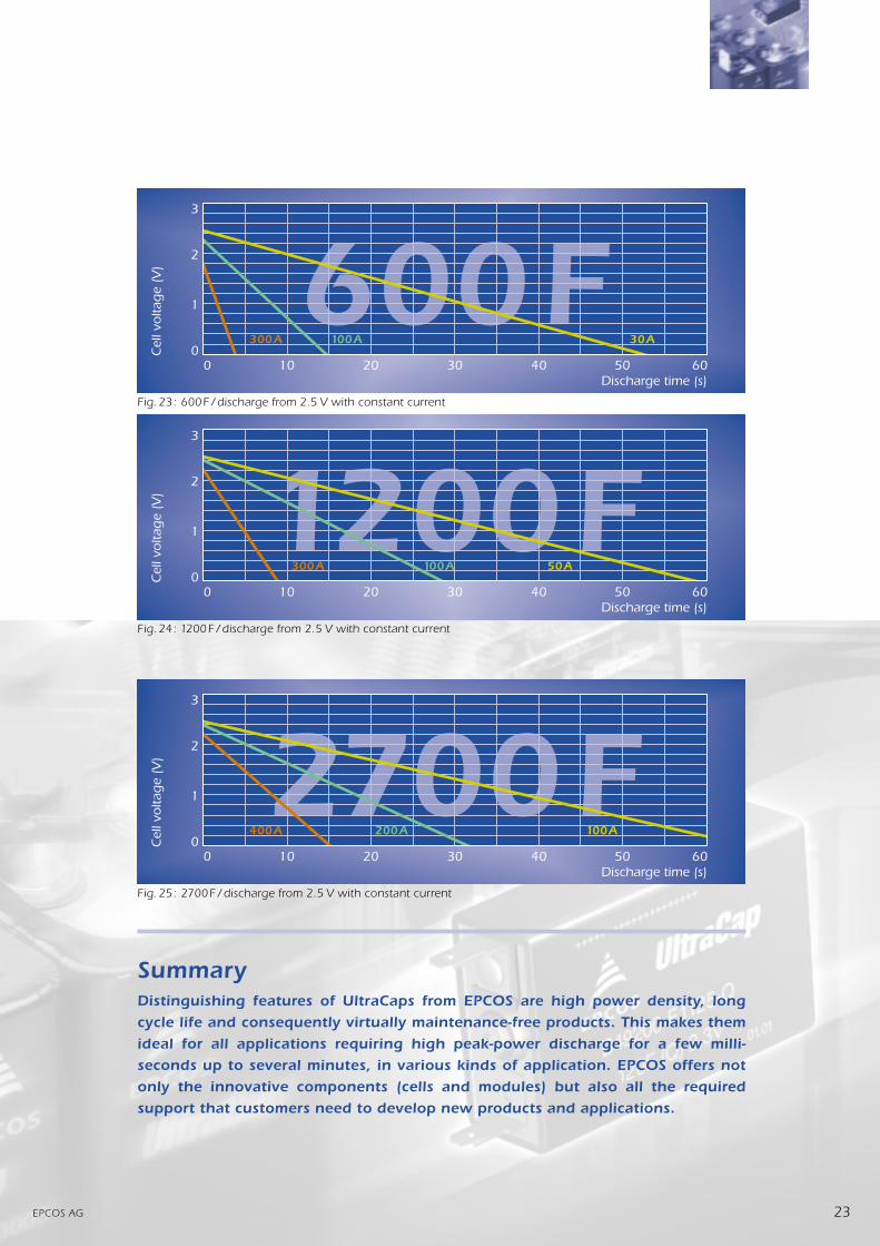
Fig.23: 600F/discharge from 2.5 V with constant current
Fig.24: 1200F/discharge from 2.5 V with constant current
Fig.25: 2700F/discharge from 2.5 V with constant current
SummaryDistinguishing features of UltraCaps from EPCOS are high power density, long
cycle life and consequently virtually maintenance-free products. This makes them
ideal for all applications requiring high peak-power discharge for a few milli-
seconds up to several minutes, in various kinds of application. EPCOS offers not
only the innovative components (cells and modules) but also all the required
support that customers need to develop new products and applications.

)4'37 %+
Herausgegeben von EPCOS AG, Marketing KommunikationPostfach 801709, 81617 München, DEUTSCHLAND (089) 636-09, FAX (089) 636-2 2689 EPCOS AG 2000. Alle Rechte vorbehalten. Vervielfältigung, Veröffentlichung, Verbreitung und Verwertung dieserBroschüre und ihres Inhalts ohne ausdrückliche Genehmigung der EPCOS AG nicht gestattet.Mit den Angaben in dieser Broschüre werden die Bauelemente spezifiziert, keine Eigenschaften zugesichert. Bestellungenunterliegen den vom ZVEI empfohlenen Allgemeinen Lieferbedingungen für Erzeugnisse und Leistungen derElektroindustrie, soweit nichts anderes vereinbart wird. Diese Broschüre ersetzt die vorige Ausgabe. Fragen über Technik,Preise und Liefermöglichkeiten richten Sie bitte an den Ihnen nächstgelegenen Vertrieb der EPCOS AG oder an unsereVertriebsgesellschaften im Ausland. Bauelemente können aufgrund technischer Erfordernisse Gefahrstoffe enthalten.Auskünfte darüber bitten wir unter Angabe des betreffenden Typs ebenfalls über die zuständige Vertriebsgesellschafteinzuholen.
Published by EPCOS AG, Marketing CommunicationsP.O.B. 801709, 81617 Munich, GERMANY ++49 89 636-09, FAX (089) 636-2 2689 EPCOS AG 2000. All Rights Reserved. Reproduction, publication and dissemination of this brochure and the informationcontained therein without EPCOS’ prior express consent is prohibited.The information contained in this brochure describes the type of component and shall not be considered as guaranteedcharacteristics. Purchase orders are subject to the General Conditions for the Supply of Products and Services of theElectrical and Electronics Industry recommended by the ZVEI (German Electrical and Electronic Manufacturers’Association), unless otherwise agreed. This brochure replaces the previous edition. For questions on technology, prices anddelivery please contact the Sales Offices of EPCOS AG or the international Representatives. Due to technical requirementscomponents may contain dangerous substances. For information on the type in question please also contact one of ourSales Offices.