ultrafast manipulation of the magnetization j. stöhr sara gamble and h. c. siegmann, slac, stanford...
Post on 19-Dec-2015
215 views
TRANSCRIPT
Ultrafast Manipulation of the Magnetization
J. Stöhr Sara Gamble and H. C. Siegmann,
SLAC, Stanford
A. Kashuba Bogolyubov Institute for Theoretical Physics, Kiev, Ukraine
The ultrafast technology gap
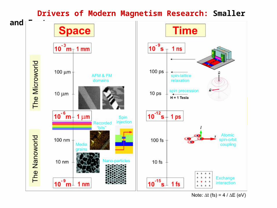
Drivers of Modern Magnetism Research: Smaller and Faster
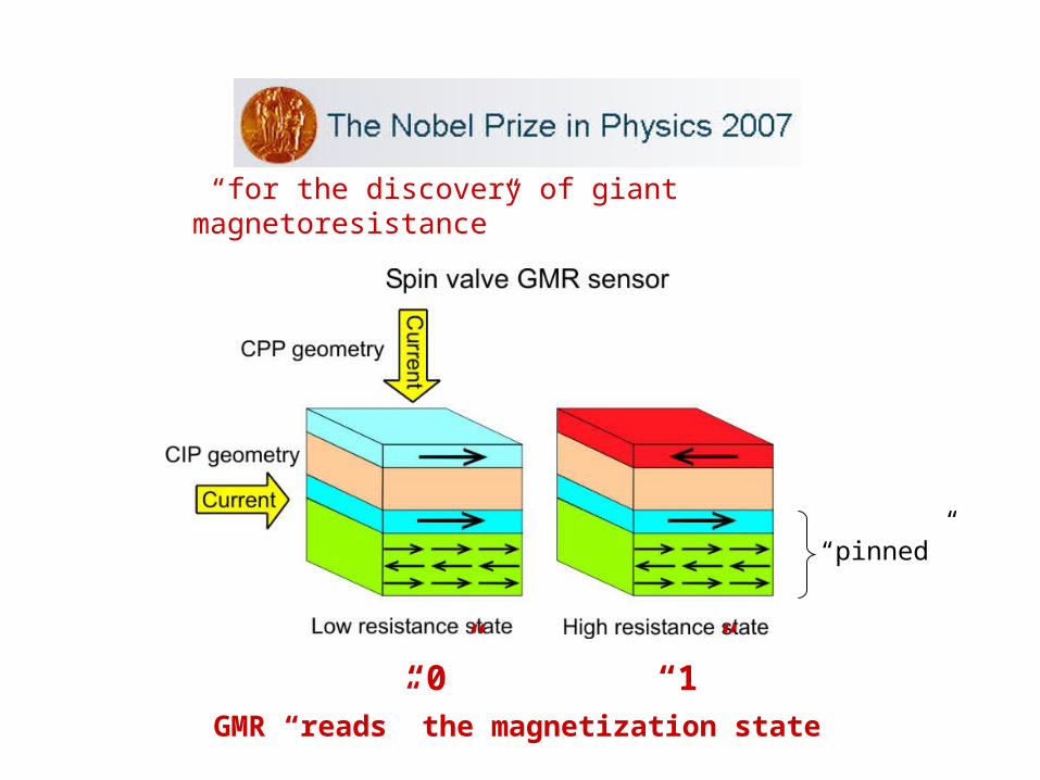
“for the discovery of giant magnetoresistance”
GMR “reads” the magnetization state
“pinned”
“0” “1”
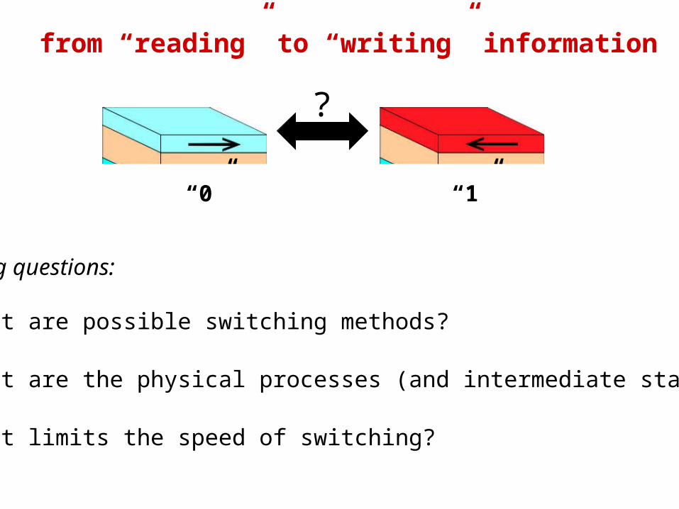
from “reading” to “writing” information
?
The big questions:
• What are possible switching methods?
• What are the physical processes (and intermediate states)?
• What limits the speed of switching?
“0” “1”
exchange orspin-orbit
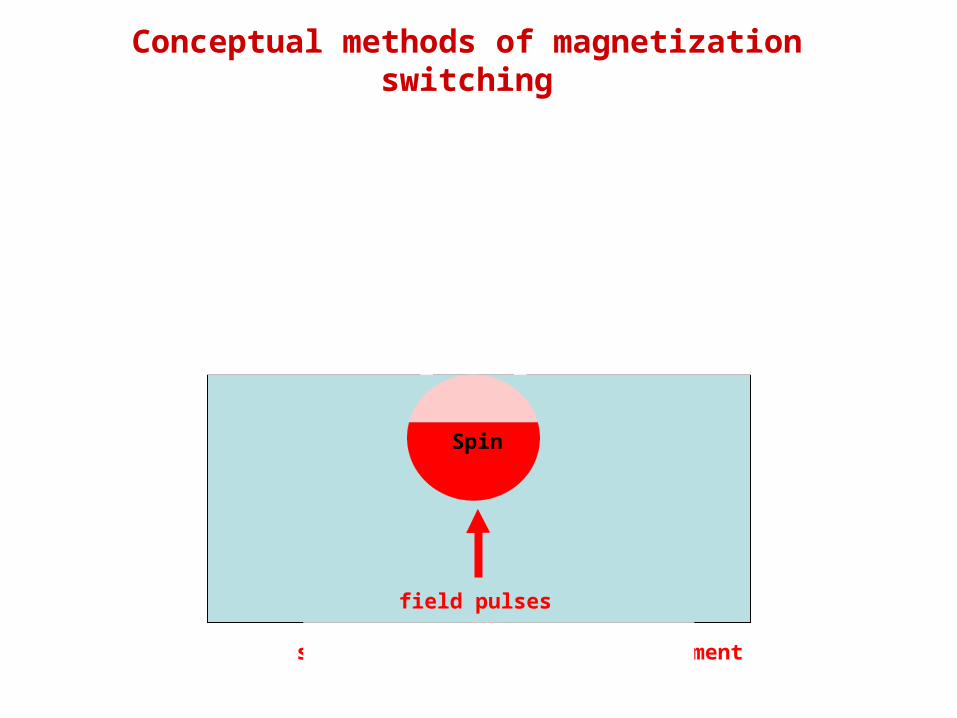
Conceptual methods of magnetization switching
Optical pulse Lattice shock
Electrons Phonons
Spin
~ 1 ps
~ 100 ps
electrons move in femtoseconds
atoms move in picoseconds
?
field pulses or
spin currents into magnetic element
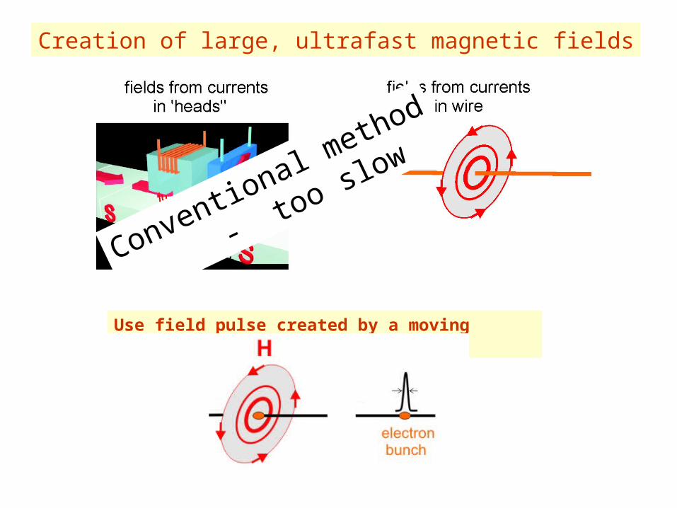
Creation of large, ultrafast magnetic fields
Conventional method
- t
oo slow
Use field pulse created by a moving electron bunch
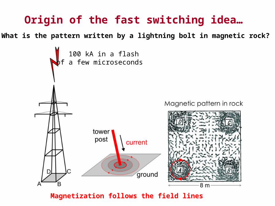
Origin of the fast switching idea…What is the pattern written by a lightning bolt in magnetic rock?
100 kA in a flash of a few microseconds
Magnetization follows the field lines
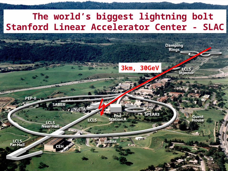
The world’s biggest lightning boltStanford Linear Accelerator Center - SLAC
3km, 30GeV
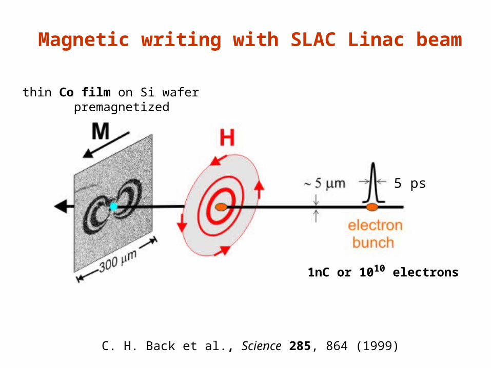
thin Co film on Si wafer premagnetized
Magnetic writing with SLAC Linac beam
C. H. Back et al., Science 285, 864 (1999)
5 ps
1nC or 1010 electrons
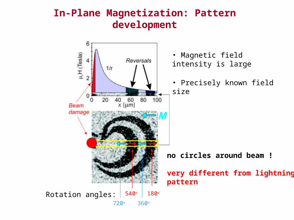
In-Plane Magnetization: Pattern development
• Magnetic field intensity is large
• Precisely known field size
540o
360o
180o
720o
Rotation angles:
no circles around beam !
very different from lightningpattern
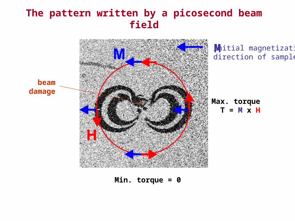
The pattern written by a picosecond beam field
Max. torque T = M x H
Min. torque = 0
initial magnetizationdirection of sample
Fast switching occurs when H M┴
beamdamage
M
end of field pulse
M
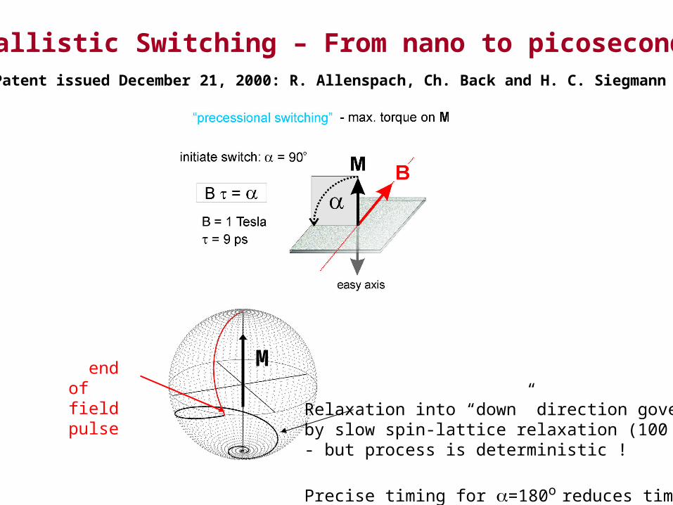
Ballistic Switching – From nano to picosecondsPatent issued December 21, 2000: R. Allenspach, Ch. Back and H. C. Siegmann
Relaxation into “down” direction governedby slow spin-lattice relaxation (100 ps)- but process is deterministic !
Precise timing for =180o reduces time
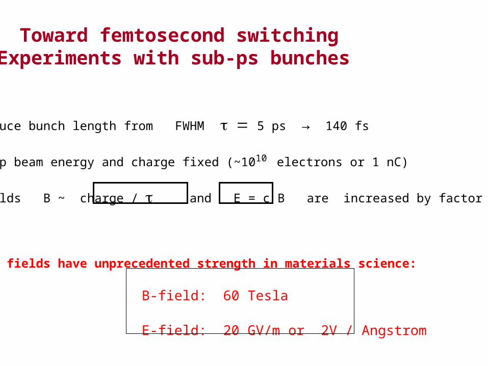
Toward femtosecond switching Experiments with sub-ps bunches
• reduce bunch length from FWHM5 ps → 140 fs
• keep beam energy and charge fixed (~1010 electrons or 1 nC)
• fields B ~ charge / and E = c B are increased by factor of 35
• our fields have unprecedented strength in materials science:
B-field: 60 Tesla
E-field: 20 GV/m or 2V / Angstrom
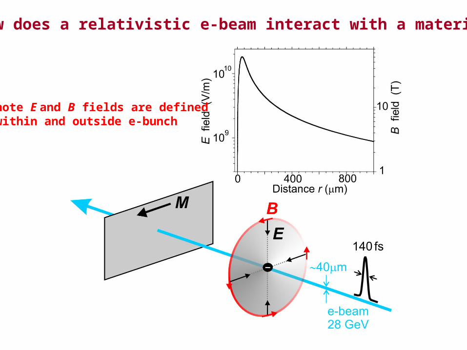
How does a relativistic e-beam interact with a material ?
note E and B fields are definedwithin and outside e-bunch
10 nm Co70Fe30
on MgO (110)
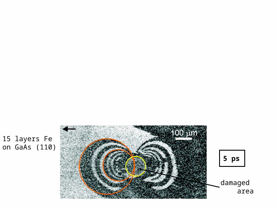
Magnetic pattern is severely distorted for short bunch
140 fs
5 ps
damaged area
15 layers Feon GaAs (110)
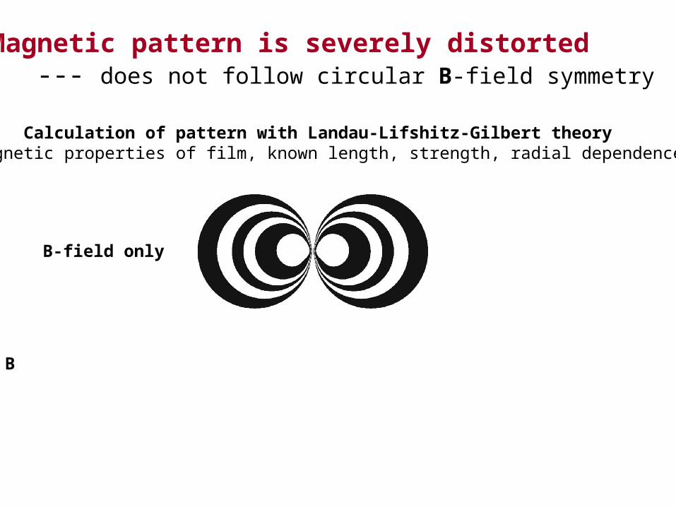
Magnetic pattern is severely distorted --- does not follow circular B-field symmetry
Calculation of pattern with Landau-Lifshitz-Gilbert theoryknown magnetic properties of film, known length, strength, radial dependence of fields
B-field only
B-field and E-field
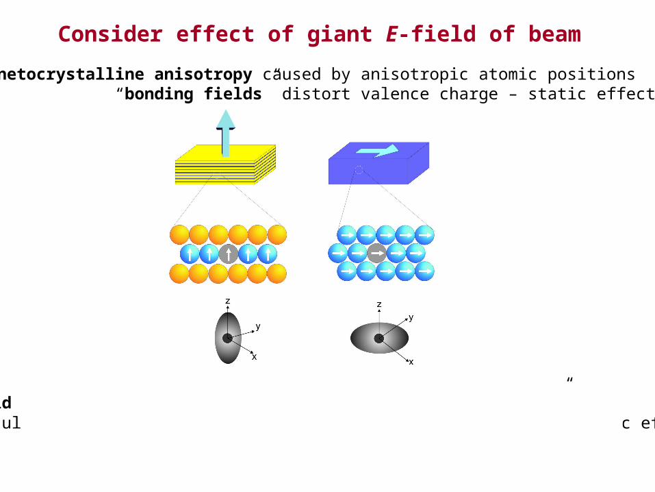
Consider effect of giant E-field of beam
Beam field E ~ 1010 V / m = 1 V / Å comparable to “bonding fields” leads to ultrafast distortion of valence charge - all electronic dynamic effect
all new “magnetoelectronic anisotropy” – ultrafast !
magnetocrystalline anisotropy caused by anisotropic atomic positions “bonding fields” distort valence charge – static effect
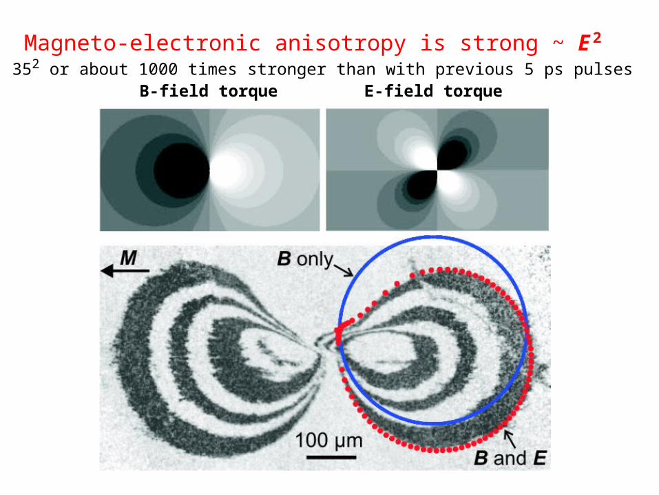
B-field torque E-field torque
Magneto-electronic anisotropy is strong ~ E 2
352 or about 1000 times stronger than with previous 5 ps pulses
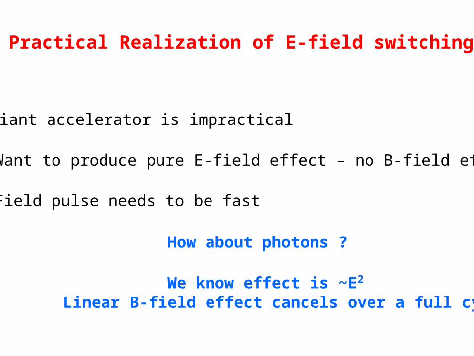
Practical Realization of E-field switching
• Giant accelerator is impractical
• Want to produce pure E-field effect – no B-field effect
• Field pulse needs to be fast
How about photons ? We know effect is ~E2 Linear B-field effect cancels over a full cycle
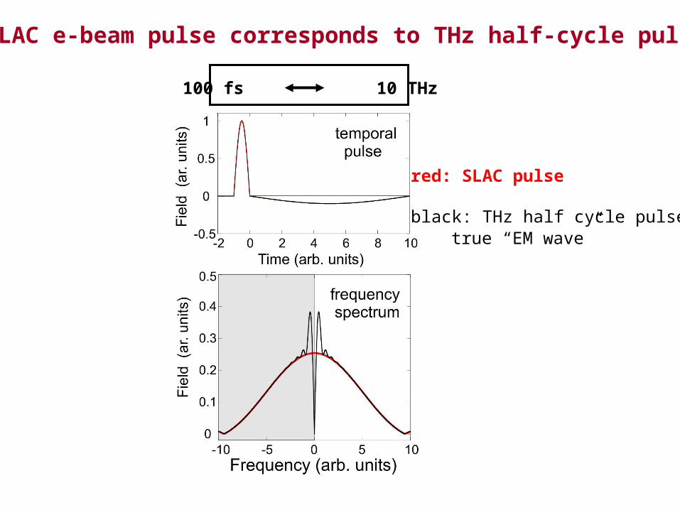
SLAC e-beam pulse corresponds to THz half-cycle pulse
red: SLAC pulse
black: THz half cycle pulsetrue “EM wave”
100 fs 10 THz
Can sample handle intense THz pulse ?
Heating of sample would be problem….
• Need strong THz radiation - not readily available
• Presently only produced by accelerators
• Laser generated THz about 100 times weaker at present
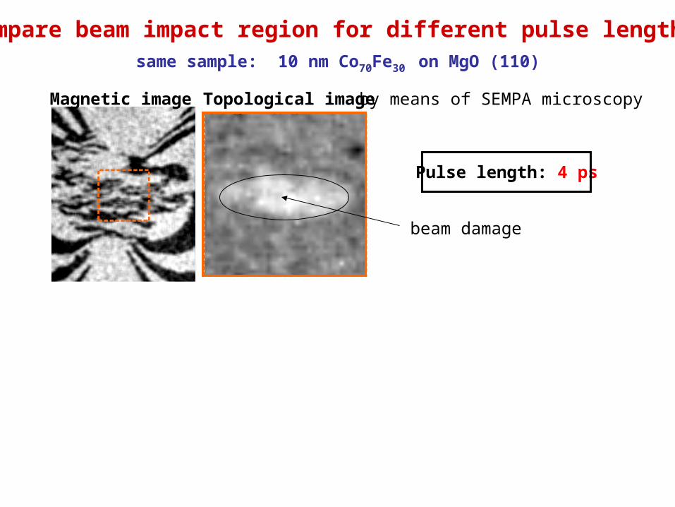
Pulse length: 4 ps
Pulse length: 140 fs
Compare beam impact region for different pulse lengths
Magnetic image Topological image by means of SEMPA microscopy
same sample: 10 nm Co70Fe30 on MgO (110)
beam damage
35 times shorter pulse & stronger fields cause
no heating, no damage !
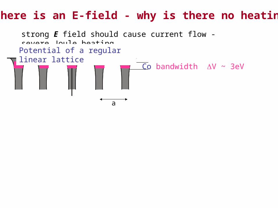
If there is an E-field - why is there no heating?
Co bandwidth V ~ 3eV
a
E ~ 1010 V/m
a = 0.25 nm
V = e E a ~ 2.5 eV
potential gradient leads to breakup of conduction path no current flow due to field – no heating
Potential along E field direction
Offset of “bands” ~ bandwidth
strong E field should cause current flow - severe Joule heating
Potential of a regular linear lattice
• Unusual E and B field effects
• No apparent heating or damage by beam
• Extreme THz science just starting….
Summary
material behave very strange in extreme fields !