ultralok roof system - aci building systems, llc installation...ultralok roof system installation...
TRANSCRIPT

Installation Guide
UltraLokRoof System

Page 1Dwg: Date: January 2010
UltraLok Roof System Installation Guide
I
INDEX
1.0 GENERAL 1.1 Purpose of the Installation Guide ...................................................................................................... 1-1 1.2 Customer’s Responsibility ................................................................................................................ 1-12.0 SAFE ROOF INSTALLATION 2.1 Erector’s Responsibility .................................................................................................................... 2-1 2.2 OSHA ................................................................................................................................................ 2-1 2.3 Walking & Working on Roof Panels...................................................................................................2-1 2.4 Handling Roof Materials in Strong Winds ......................................................................................... 2-23.0 CHECKING THE STRUCTURE 3.1 Completed and Braced ..................................................................................................................... 3-1 3.2 Lateral Stability ................................................................................................................................. 3-1 3.3 Alignment .......................................................................................................................................... 3-14.0 RECEIVING & HANDLING ROOF MATERIALS 4.1 Material Inventory ............................................................................................................................. 4-1 4.2 Equipment for Unloading and Lifting ................................................................................................. 4-1 4.3 Lifting Roof Panel Bundles ............................................................................................................... 4-1 4.4 Field Storage of Roof Materials ........................................................................................................ 4-2 4.5 Handling Individual Roof Panels ....................................................................................................... 4-35.0 ROOF INSTALLATION BASICS 5.1 Proper Tools ..................................................................................................................................... 5-1 5.2 Equipment List .................................................................................................................................. 5-1 5.3 Sealants.............................................................................................................................................5-1 5.4 Fasteners...........................................................................................................................................5-2 5.5 Field Cutting Panels and Flashing .................................................................................................... 5-36.0 ROOF PANEL LAYOUT 6.1 Sheeting Direction and Modularity .................................................................................................... 6-1 6.2 Layout & Checking for Coverage ...................................................................................................... 6-1 6.3 Appearance Considerations .............................................................................................................. 6-17.0 INSPECTION OF ROOF ASSEMBLY DURING INSTALLATION 7.1 Importance of Inspection .................................................................................................................. 7-1 7.2 Inspection List....................................................................................................................................7-18.0 STANDARD PARTS 8.1 General ............................................................................................................................................. 8-1 8.2 Standard Parts Details.......................................................................................................................8-29.0 ROOF INSTALLATION DETAILS 9.1 General ............................................................................................................................................. 9-1 9.2 Preparation for Roof Panel Installation..............................................................................................9-2 9.3 Roof Panel Installation.......................................................................................................................9-8 9.4 End Dam Installation ......................................................................................................................... 9-31 9.5 Termination Panel Installation ........................................................................................................... 9-39 9.6 Rake Trim Installation ....................................................................................................................... 9-48 9.7 Rake Transition Installation ............................................................................................................... 9-54 9.8 Ridge Cover Installation .................................................................................................................... 9-58 9.9 High Eave Transition Installation ...................................................................................................... 9-64 9.10 Eave Gutter Installation .................................................................................................................. 9-68 9.11 Hip and Valley Installation ............................................................................................................... 9-72
INDEX

UltraLok Roof System Installation Guide
Page 2Dwg: Date: January 2010
1-1
1.0 GENERAL1.1 Purpose of the Installation Guide
This installation guide is provided to ACI Metal Roofing Systems customers and their erectors as the recommended procedure for the correct assembly of the ACI Metal Roof-ing Systems Standing Seam Roof System.
This guide is intended to be used in conjunction with the project’s erection drawings to help plan and organize the installation of the ACI Metal Roofing Systems Standing Seam Roof System. The erection drawings identify the applicable roof conditions and govern specific part arrange-ments. The instructions will help you identify parts, establish the installation sequence, demonstrate correct assembly, and point out any areas or procedures requiring special emphasis or attention.
This installation guide applies to the standard ACI Metal Roofing Systems Standing Seam Roof System. Custom roof conditions, including custom details and instructions, will be covered by the erection drawings. In case of conflict between this installation guide and the erection drawings, the erection drawings will have precedence.
1.2 Customer’s Responsibility
The customer is responsible for proper installation of the roof in accordance with the erection drawings and this in-stallation guide, and in accordance with good engineering and construction practices.
The customer must take the responsibility for selecting a competent erector, insist that the work be performed by qualified and experienced standing seam metal roof install-ers, insist that the erector take time to study and understand this guide, then assure that the erector correctly follows the guide’s instructions.
ACI Metal Roofing Systems does not guarantee and is not liable for the quality of erection. ACI Metal Roofing Systems is not responsible for building defects that may be attributed to improper erection or the negligence of other parties.
Clarification concerning the ACI Metal Roofing Systems roof installation should be directed to the ACI Metal Roof-ing Systems Customer Service Manager.
Contact the ACI Metal Roofing Systems office:
ACI Metal Roofing Systems10009 Hwy 6 West
Batesville, MS 38606Phone: (662) 563-3613
Fax: (662) 563-0655
GENERAL

Page 3Dwg: Date: January 2010
UltraLok Roof System Installation Guide
2-1
2.0 SAFE ROOF INSTALLATION2.1 Erector’s Responsibility
The erector of the roof system is responsible for the safe execution of this installation guide. These instructions are intended to describe the sequence and proper placement of parts. They are not intended to prescribe comprehensive safety procedures.
If the erector cannot safely assemble the roof in accordance with these instructions, it is the responsibility of the erector to stop the work and contact ACI Metal Roofing Systems to determine alternate assembly procedures.
2.2 OSHA
The Occupational Safety and Health Act (OSHA) has pro-mulgated many regulations applicable to the installation of this or any other roof system. These regulations, identified as Part 1926, Safety and Health Regulations for Construc-tion, are available from any government bookstore. The objective of the OSHA standards is to protect the worker from injury or illness. These OSHA regulations should be recognized as job site requirements and be fully complied with.
Failure to do so may result in substantial fines in the event of an OSHA inspection. Safe installation practices may be further defined and made mandatory by state or local ordinances.
Maintaining good housekeeping on the jobsite is recognized as being important to both OSHA compliance and to suc-cessful job completion.
2.3 Walking & Working on Roof Panels
Do not walk on the last installed panel run, as the unsecured edge could collapse under a person’s weight. When install-ing clips or making endlap connections, etc., stand where the roof structural will support your weight.
An approved and safe walking platform should be used in high traffic areas to prevent the roof panel from being deformed, scratched, or scuffed.
A. PLACING PANELS ON THE STRUCTUREDo not place bundles of panels on the roof structure without first verifying the structure will safely support the concen-trated weight of the panels and the weight of the installa-tion crew. Some roof structures may not be designed to support the weight of a full panel bundle without additional structure support.
B. WALKING ON ROOF PANELSDo not use a roof panel as a working platform. An unse-cured panel could collapse under the weight of a person standing between purlins or at the panel end.
F_PCO_000R00BRSSAFE ROOF INSTALLATION
Assembled Sidelap (Typ.)
Leading Roof Panel
Leading Edge
CORRECT Step ONLY on secured roof panels.
CAUTION DO NOT step on leading (unsecured) roof panel.
Leading Roof Panel
Leading Edge Assembled Sidelap (Typ.)

UltraLok Roof System Installation Guide
Page 4Dwg: Date: January 2010
2.0 SAFE ROOF INSTALLATION2.3 Walking & Working on Roof Panels (Continued)
C. SAFETY EQUIPMENTThe use of safety equipment for the roof panel installation is recommended at all times during the installation process.However, when using lanyards, ensure that the clasp, belt hooks and wire cables are covered in such a manner that they will not scratch the panel surface if accidentally dragged along the panel.
D. CREW SIZEThe length of the individual roof panels should be consid-ered when determining the crew size. It is recommended that under normal conditions, there be one person for every ten feet of panel length, plus one.
E. PANEL OVERHANGDo not stand on the end of unsupported (cantilevered) panels at the eave or ridge. Standing on the cantilever portion may result in panel collapse.
F. POINT LOADSWhen properly supported by the structurals, panels are designed to support uniform loads, which are evenly dis-tributed over the panel surfaces. Point loads that occur in small or concentrated areas, such as heavy equipment, ladders or platform feet may cause panel deformation or even panel collapse.
G. SLICK SURFACESPanel surfaces and structural steel surfaces are hard, smooth, and nonabsorbent, which causes these surfaces to be very slick when wet or covered with snow or ice. Even blowing sand or heavy dust can make these surfaces dif-ficult to walk on without slipping.
Unpainted panel surfaces are often coated with oil to accom-modate the panel-fabrication process. Although designed to wash away or evaporate during normal weather, the oil on new panels can be extremely slick, especially during periods of light rain or dew.
Caution must be exercised to prevent slipping and falling onto the roof surface or even sliding off the roof. Non-slip footwear is a necessity and non-slip working platforms are recommended.
H. ELECTRICAL CONDUCTANCEMetal panels are excellent electrical conductors. A common cause of injury is the contact of metal panels with power lines during handling and installation. The location of all power lines must be noted and, if possible, flagged. The installation process must be routed to avoid accidental contact with all power lines and high voltage services and equipment. All tools and power cords must be properly insulated and grounded and the use of approved ground fault circuit breakers is recommended.
I. FALSE SECURITY OF INSULATIONBlanket and board insulation blocks the installer’s view of the ground below the roof. Serious injury can occur when the installer gets a false sense of security because he can-not see the ground and steps through the insulation.
J. SHARP EDGESSome edges of panels and flashing are razor sharp and can cause severe cuts if proper protective hand gear is not worn. Be careful not to injure others while moving panels and flashing.
2.4. Handling Roof Materials in Strong Winds
Do not attempt to move panels in strong winds. Wind pressure can easily cause a man to lose balance and fall. Strong wind uplift on a panel can lift the weight of the man carrying the panel.
Loose, wind borne panels are very dangerous and can cause severe injury and damage.
Secure stacks of panels with banding or tie-downs, so wind will not blow the panels off the roof. Clamp individual unsecured panels to the roof structurals. Clamp or block panel bundles and accessory crates to prevent them from sliding down the roof slope.
SAFE ROOF INSTALLATION2-2

Page 5Dwg: Date: January 2010
UltraLok Roof System Installation Guide
3.0 CHECKING THE STRUCTURE
3.1 Completed and Braced
Before placing materials and workers on the roof structure to start roof installation, it must be confirmed that the structure is designed to accommodate the material and erection loads as well as the appropriate live loads and wind uplift loads.It also must be determined that the structure is complete
and structurally sound with all structural connections and bracing in place and secure.
3.2 Lateral Stability
The sliding clip method of attaching the roof panels to the roof structurals provides only limited lateral stability and diaphragm bracing to the roof structurals.
Before placing materials on the roof and starting the roof installation, confirm that the necessary roof bracing and sag angles, strapping or bridging for purlin stability is in place and secured.
3.3 Alignment
Prior to installation, roof structurals should be checked for overall dimensions and evenness of plane. The roof structurals should also be checked to verify the roof system can be installed without interference. Also, roof structurals nearest the panel endlaps, ridge or high eave should be checked for correct location to properly accommodate the roof components.
A. TOLERANCESTo assure the roof system’s correct fit-up and designed weather tightness, the structure must be aligned within the following tolerances:
Out of Square — The roof system can accommodate 1/8” of sawtooth of the roof panel ends at the eave, ridge and panel splices. This means the allowable out of square of the rake line relative to the eave line and ridge line is 1/2” for each 10’ of rake run.
Structure Width and Eave Straightness — The roof system is designed to accommodate ±2” of overall struc-ture width error, or ±1” of eave straightness error at each eave.
To assure that the accumulation of the structure width er-ror and eave straightness error does not exceed the roof system’s tolerance, the structure width should be measured from eave line to eave line at each rake, at the first frame line from each rake and at each point where there is a sig-nificant error or change in eave straightness (this usually occurs at a frame line or at a wind column).
Structure Length and Rake Straightness — The roof system is designed to accommodate ±2” of overall struc-ture length error, or ±1” of rake straightness error at each
rake.
To assure that the accumulation of structure length error and rake straightness error does not exceed the roof system’s tolerance, the structure length should be measured from rake line to rake line at each eave, at the ridge and at each point where there is a significant error or change in rake straightness (this usually occurs at an end rafter splice).
B. MEASURINGStructure length and width may be measured with a steel measuring tape from the face of the eave or rake member to the face of the opposite eave or rake member. The mea-suring tape must be parallel to the relative eave or rake line and must be stretched taut.
Eave and rake straightness may be determined by mea-suring deviations from a string line, which is stretched taut along the eave or rake line.
C. AESTHETIC ACCEPTANCEAlthough these structure alignment tolerances will allow for reasonable roof component fit-up and ease of installa-tion, the extremes of these tolerances may be aesthetically objectionable and should be confirmed with the customer before starting the roof installation.
D. CORRECTIONSAny structure alignment error, which exceeds the above stated tolerances, must be corrected before roof installation can begin. If it is decided that the structure alignment errors cannot be corrected, alternate roof details may have to be developed. The alternate details may require additional materials, modified parts (with additional cost, fabrication and delivery time) and additional installation time. ACI Metal Roofing Systems cannot assure the performance of such alternate details.
CHECKING THE STRUCTURE3-1

UltraLok Roof System Installation Guide
Page 6Dwg: Date: January 2010
Panel Spreader Bundle
Fork Lift
Fork Blades
Web Slings
Panel Bundle
5’ Minimum
3 Equal Spaces, Panel length 35' or less
4 Equal Spaces, Panel length more than 35' Limited to 25'
Panels over 25'
4.0 RECEIVING & HANDLING ROOF MATERIALS4.1 Material Inventory
Your material is carefully inspected and crated before leav-ing the plant and accepted by the transportation company as being complete and in satisfactory condition. It is the carrier’s responsibility to deliver the shipment intact. It is the consignee’s responsibility to inspect the shipment for damages and shortages when it is delivered.
Conducting a material inventory at the time of delivery is essential. By conducting the materials inventory, the erec-tor is able to identify any material shortage or damage and avoid stopping installation later because of such shortage or damage.
It is imperative that any shortages or damage of the deliv-ered materials be noted at once and clearly marked on the bill of lading before signature of acceptance. Notify ACI Metal Roofing Systems immediately of any conflicts. ACI Metal Roofing Systems will not be responsible for shortages or damages unless they are noted on the bill of lading.
In the case of packaged components (such as clips, fas-teners and sealants, etc.), the quantities are marked on their container and should be checked against the bill of materials. ACI Metal Roofing Systems must be notified of any shortages or concealed damage within 15 days of delivery.
4.2 Equipment For Unloading and Lifting
Hoisting equipment is necessary to unload and position the panels and accessory crates for site storage and instal-lation. The equipment must have sufficient capacity and reach to place the material where it is required for efficient installation.
Slings will be required to minimize panel damage. The recommended slings are nylon straps of 6” minimum width and of sufficient length to accommodate the panel bundle girth.
A spreader bar will be required for the longer panel crates to assure correct sling spacing and uniform lifting. The spreader bar must be large enough to handle the maximum panel bundle weight and length.
A forklift is handy for unloading and placing shorter panel and accessory crates.
4.3 Lifting Roof Panel BundlesUnder normal conditions, panel crates less than 35’ long can be lifted with two slings spaced at third points. Panel crates longer than 35’ can be lifted with three slings located at quarter points using a spreader bar to achieve correct sling spacing for uniform lift.
Slings should be located under the cross boards. Loads should always be checked for secure hook-up, proper
balance, and lift clearance. Tag lines should be used if necessary to control the load during lifting, especially if operating in the wind.
Panel crates less than 25’ long may be lifted with a forklift only if the forks are spread at least 5’ apart and blocking is used to prevent panel damage by the forks.
F_PCO_001R00BRS RECEIVING AND HANDLING ROOF MATERIALS4-1
Page 7Dwg: Date: January 2010
UltraLok Roof System Installation Guide
4.0 RECEIVING & HANDLING ROOF MATERIALS
4.4 Field Storage of Roof Materials
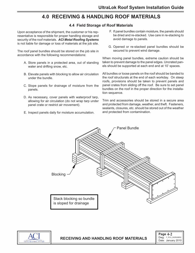
Upon acceptance of the shipment, the customer or his rep-resentative is responsible for proper handling storage and security of the roof materials. ACI Metal Roofing Systems is not liable for damage or loss of materials at the job site.
The roof panel bundles should be stored on the job site in accordance with the following recommendations:
A. Store panels in a protected area, out of standing water and drifting snow, etc.
B. Elevate panels with blocking to allow air circulation
under the bundle.
C. Slope panels for drainage of moisture from the panels.
D. As necessary, cover panels with waterproof tarp, allowing for air circulation (do not wrap tarp under panel crate or restrict air movement).
E. Inspect panels daily for moisture accumulation.
F. If panel bundles contain moisture, the panels should be dried and re-stacked. Use care in re-stacking to avoid damage to panels.
G. Opened or re-stacked panel bundles should be secured to prevent wind damage.
When moving panel bundles, extreme caution should be taken to prevent damage to the panel edges. Uncrated pan-els should be supported at each end and at 10’ spaces.
All bundles or loose panels on the roof should be banded to the roof structurals at the end of each workday. On steep roofs, provisions should be taken to prevent panels and panel crates from sliding off the roof. Be sure to set panel bundles on the roof in the proper direction for the installa-tion sequence.
Trim and accessories should be stored in a secure area and protected from damage, weather, and theft. Fasteners, sealants, closures, etc. should be stored out of the weather and protected from contamination.
RECEIVING AND HANDLING ROOF MATERIALS
Panel Bundle
Blocking
Stack blocking so bundle is sloped for drainage
F_PCO_002R00BRS
4-2

UltraLok Roof System Installation Guide
Page 8Dwg: Date: January 2010
4.0 RECEIVING & HANDLING ROOF MATERIALS
4.5 Handling Individual Roof Panels
To lift individual panels, lift one side of the panel by the seam letting it hang naturally to prevent buckling. Pick-up points should not be more than 10’ apart. Do not pick-up panels by the ends only, or in a flat position.
If the individual panels are to be lifted to the roof by hand line, the common method is to use the vice grip “C” clamps. Position the clamps on the flat of the panel as close as pos-sible to one edge so the panel is lifted in a vertical position.
The jaws of the vice grips must be padded to prevent dam-age to the panel surface. The clamps should be uniformly spaced, no more than 10’ apart and the hand lines must be pulled in unison so that uneven lifting does not buckle the panel. Be sure the clamps are tight on the panel and the line is secure to prevent dropping the panel which can result in personal injury and property damage.
RECEIVING AND HANDLING ROOF MATERIALS
Roof Panel
10’ Maximum
10’ Maximum
F_PCO_003R00BRS
4-3

Page 9Dwg: Date: January 2010
UltraLok Roof System Installation Guide
5.1 Proper ToolsBefore starting paneling, be sure that the proper equip-ment and tools are on hand. The tools must be in good operating condition and operators should adhere to safety precautions at all times.
Improperly operating tools, too few tools, inadequate pow-er source, or other equipment deficiencies slow down the installation process. The cost of inefficient working is usually greater than the cost of providing good equipment.
5.0 ROOF INSTALLATION BASICS
5.2 Equipment List
The following tools and equipment should be considered for efficient installation of the ACI Metal Roofing Systems standing seam roof. Actual tools and equipment required may vary due to variations in building type and construction.
This list should not be interpreted as a limitation to your inventory of installation equipment.
*UL Rib Clamp — Minimum of (4) required*UL Seam Clamp — Minimum of (2) required*UL Motorized Seaming Machine*ESE #812 Manual Seaming Tool20 amp UL Motorized Seaming MachineScrew Guns — Designed for use with self-drilling screwsSocket Extensions — 6” extension for screw gunHex Socket Heads — 5/16” and 3/8”, magneticDrill Motor — 1/4” capacityDrill Bits — AssortmentSheet Metal Cutter — or power shears or nibbler“C” Clamps — vise grip, with swivel padsPop Rivet Tool — 1/8” capacitySheet Metal Shears — left and right cut
Steel Measuring Tape — 12’, 50’, 100’Nylon StringChalk Line — (No Red Chalk)BroomsMarking Pen — (No Lead Pencil)Caulk Guns — for 1/10 gallon sealant tubesPower Source and Extension Cords — capable of handling
the total equipment requirements, including 20-amp seamer machine, without power drop due to extension cord length.
*These tools are specifically designed for the ACI Metal Roofing Systems Roof Panel and are available from the ACI Metal Roofing Systems.
5.3 Sealants
A. TEMPERATURE EFFECTSTemperature extremes must be considered during instal-lation of the roof due to the sensitivity of sealants. The recommended installation temperature range is 20º F to 120º F. At colder temperatures, the sealant stiffens resulting in loss of adhesion and compressibility. At hotter tempera-tures, the sealant becomes too soft for practical handling. On cold but sunny days, the panel’s surface may become warm enough to accept the application of a heated sealant even though the air temperature is below 20º F.
When overnight temperatures fall below freezing, the seal-ant should be stored in a heated room so it will be warm enough to use the following day. On hot days, the sealant cartons should be stored off the roof in a cool and shaded area. While on the roof, sealant rolls should be kept shaded until actual use.
In very cold weather, it is recommended that the fasteners be tightened slowly and only tight enough that the sealant is in full contact with the panel or flashing. Then on the next sunny day, complete the tightening process after the sun warms the panel and flashing surfaces.
B. CONTAMINATIONTo assure proper adhesion and sealing, the sealant must have complete contact with adjoining surfaces and achieve 30% compression. Contaminants such as water, oil, dirt and dust prevent such contact. The panel and flashing surfaces must be dry and thoroughly cleaned of all contaminants. Before applying tape sealant, the sealant should be checked for contaminants. If the sealant surfaces are contaminated, it must not be used.
During cool weather, condensation or light mist can accu-mulate on the panel and flashing surface and not be easily noticed. It is recommended that sealants always be kept under protective cover and that the panel and flashing sur-faces be wiped dry immediately before installation.
Tape sealant is provided with a protective paper to reduce contamination. Incomplete removal of the protective paper will prevent the sealant’s adhesion to the panel or flashing surfaces. Always check that the protective paper is com-pletely removed. Do not remove the protective paper until immediately before the panel or flashing is installed over the sealant.
ROOF INSTALLATION BASICS5-1

UltraLok Roof System Installation Guide
Page 10Dwg: Date: January 2010
5.0 ROOF INSTALLATION BASICS
5.3 Sealants (Continued)
C. COMPRESSIONTo assure proper adhesion and seal, the tape sealant must be compressed between the panel and flashing surfaces with firm and uniform pressure. In most cases, the required pressure is applied by the clamping action of screws pulling the adjoining surfaces together. However, the tape sealant’s resistance to pressure becomes greater in cold weather.
During cold weather, the fasteners must be tightened slowly to allow the sealant time to compress. If the fasteners are tightened too fast, the fastener may strip out before the sealant compresses adequately, or the panel or flash may deform in the immediate area of the fastener, leaving the rest of the sealant insufficiently compressed.
D. INSIDE CORNERSAn inside radius, such as where the panel flat meets a rib, is usually the most critical area to seal. A common mistake for the installer, is to bridge the sealant across the inside radius. When the lapping panel or flashing is pushed into place, the bridged sealant is stretched and thinned. The sealant may then be too thin to adequately seal this critical area.
When tape sealant is applied at an inside radius, it is recom-mended that the sealant be folded back on itself, then push the sealant fold into the radius. Do not tear but cut the tape sealant to length with a box knife or equal.
5.4 Fasteners
A. SCREW GUNUse torque control and variable speed screw guns for driv-ing self-drilling screws. 2000-2500 RPM screw gun speeds are necessary to attain efficient drilling speeds. High tool amperage (4 to 7 AMP) is required to achieve the proper torque for proper seating and to secure the fastener.
B. SOCKETSUse good quality sockets. Good fitting sockets reduce wobble and stripping of the screw heads, especially the al-loy and capped heads. They also minimize objectionable paint chipping and scuffing on colored screws and minimize damage to the protective coating on unpainted screws.
Magnetic sockets collect drill shavings, which will build up and eventually prevent the socket from seating properly on the screw heads. One method of removing the drill shav-ings is to roll up a ball of tape sealant and push the socket into the sealant.
When the socket is removed from the sealant, most of the drill shavings will remain embedded in the sealant thereby cleaning the socket. This process should be repeated as often as needed to keep the socket clear of drill shavings.
C. SOCKET EXTENSIONA 4” or 6” socket extension is recommended for installing the panel clip screws. With the extension, the screw can be driven straight down without tilting the screw gun to clear the panel or clip. Since socket extensions are slow to wear out, it is usually more cost effective to purchase socket extensions and good quality sockets rather than purchase sockets with built-in extensions.
D. INSTALLATIONBefore starting the screw, the materials to be joined must be pressed together with foot or hand pressure. The pressure must be maintained until the screw has drilled through all the materials and the threads have engaged.
ROOF INSTALLATION BASICS
INCORRECT CORRECT
Do not allow the sealant to bridge across inside radii creating voids
Roof Panel
Endlap
Fold the sealant and push the fold into the radius
Sealant
Roof Panel
Sealant Endlap
Void
Void Critical:
F_PCO_004R00BRS
5-2

Page 11Dwg: Date: January 2010
UltraLok Roof System Installation Guide
5.0 ROOF INSTALLATION BASICS
5.4 Fasteners (Continued)
Most self-drilling screws require 20 pounds of pressure to maintain the drilling action and to start the thread cutting action. Also, applying such pressure before starting the screw gun will usually prevent tip walking or wandering.
If too little pressure is applied, the drill point may not cut into the metal and the point will heat up and become dull. If the pressure is too heavy, the bottom material may be deflected away, causing a standoff condition, or the drill tip may be broken or split.
Screws must be held perpendicular to the panel or flashing surface during starting and driving.
For proper seating of the fastener-sealing washer, the panel or flashing surface must be clean and drill shavings must be removed from under washers before seating. The fastener must be driven perpendicular to the panel surface so that the washer can seat level without warping or cupping.
Do not over drive screws. Over driving can strip the threads and/or damage the sealing washer. Use screw gun with torque control set to function properly for the combina-tion of fastener size, hole size and material thickness.
The fastener should be driven tight enough to uniformly compress the washer but not so tight that the washer splits or rolls out from under it’s metal dome. The recommended procedure is to tighten the fastener until the sealing washer just starts to visually bulge from under the metal dome.
As a good installation practice, all roof installers should carry approved oversized screws. Upon stripping or break-ing a screw, the screw must be immediately removed and replaced with the appropriate oversized screw. Do not defer the screw replacement to be remembered and fixed later, or to be found by the clean-up crew. The majority of such screws will be overlooked until the customer complains of leakage.
5.5 Field Cutting Panels and Flashing
A. ABRASIVE SAW PROBLEMSAbrasive saws (circular saws with friction disks) are not recommended for cutting roof panels or flashing. Abrasive saws create high heat that may burn away the protective coating from the panel edge, causing the edge to rust.
Also, abrasive saw dust contains fine, hot steel particles, which accumulate on panel and flashing surfaces where they rust and can cause staining and rusting of those surfaces.
Rust caused by abrasive saw damage or abrasive dust particles can be excluded from warranty claims.
B. SHEARING METHODSIt is recommended that panels and flashing be cut with shears to provide a clean, undamaged cut. On shear cut edges, the protective coating extends to the edge of the cut and is often wiped over the edge to further protect the base metal.
Whenever possible, fit the material so that the factory cut edge is exposed and the field cut edge is covered.
When field cutting complex shapes, it is usually easier to cut out a 1” wide strip using both left and right hand shears. The 1” cutout provides clearance to smoothly cut the flats and the clearance to work the shears around tight corners.
When making repetitive cuts (such as cutting panels at a hip condition) it is recommended that a template be madefrom a piece of drop-off panel or flash to provide fast and accurate marking of the field cut. When using panel ma-terial for the template, cut off the top portion of the panel ribs so that the template is easily laid onto the panel being marked.
C. MARKING PANELSAvoid marking the panels for cutting, etc., in a manner that will leave visible markings and stains, etc., on the finished roof surface. Use chalk or felt tip ink markers. Do not use graphite (lead) pencils on unpainted panel surfaces, the graphite can cause rusting of the surface.
ROOF INSTALLATION BASICS5-3

UltraLok Roof System Installation Guide
Page 12Dwg: Date: January 2010
Caution: FAILURE TO MAINTAIN PANEL COVERAGE WIDTH within the specified tolerance can cause faulty roof panel seams which can result in seaming difficulty or in se-vere cases reduction in roof performance specifications.
For proper fit-up between the panel, sealant and closures or endlap parts, the panels must be held to the width dimen-sion of the panel, as designated on the erection drawings, within a 1/16” width tolerance per panel.
The accumulated coverage (start panel to finish panel) toler-ance is determined by the ability to keep the panels parallel and to correctly fit and assemble the finish rake condition.
If the roof has conditions such as fixed location penetrations, parapets, fire walls, etc., the accumulated panel coverage may require tighter tolerances for proper fit-up and weather tightness of the roof system.
6.0 ROOF PANEL LAYOUT
6.1 Sheeting Direction and Modularity
Although the ACI Metal Roofing Systems roof system is designed so it can be installed in either direction (left to right or right to left), there may be roof conditions which require a specific sheeting direction. Check the erection drawings to determine if a specific sheeting direction is required.
The recommended installation sequence is to complete each panel run from eave to ridge before starting the next panel run. This sequence will help ensure straight runs and allow the insulation to be installed immediately ahead of each panel run.
During installation of the roof, considerations must be made for maintaining panel modularity. By maintaining panel modularity, the roof panel sidelap and seam can be properly assembled, the proper roof coverage can be obtained and the standard perimeter parts will fit properly without neces-sity of field modifications or reordering of parts, etc.
6.2 Layout & Checking for Coverage
Recommended for all roofs, but a must for large or com-plex roofs, is to make a layout of the actual structure (field measured as described in section 3.3) so that the roof panel start and stop dimensions can be laid out to accommodate any structural misalignments.
When the optimal start and finish dimensions are deter-mined, a string line should be set to precisely locate the leading edge of the start panel. After the start panel is secured and engaged with the next panel, the start panel seam will be the reference line for checking accumulated panel coverage.
Panel coverage is always checked at the eave, ridge, and end splices so that non-parallel seam (or dogleg) condi-tions can be detected and corrected before they become objectionable. The coverage check should be done with a measuring tape held taut and measured to the same side of the seam and always parallel to the eave to prevent any measuring error.
Every four to six panel runs should be checked for panel modularity. This will assure that the panels are maintaining a straight line and proper coverage is being maintained. If the panels are off module, they should be corrected by equal adjustments of the next four to six panel runs.
6.3 Appearance Considerations
Although the above stated coverage tolerance will provide for reasonable ease of installation and water tightness, such visible conditions as non-parallel panel seams, dogleg of the panel seam at the end splices, non-parallel finish panel
width, and mismatch of panel seams across the ridge, may be objectionable and should be confirmed with the customer before continuing roof installation.
ROOF PANEL LAYOUT6-1

Page 13Dwg: Date: January 2010
UltraLok Roof System Installation Guide
7.0 INSPECTION OF ROOF ASSEMBLY DURING INSTALLATION
7.1 Importance of Inspection
During the roof installation, all areas of the roof system as-sembly must be frequently inspected to ensure the correct assembly in accordance with the erection drawings and this installation guide.
Failure to assemble the roof system correctly will result in roof performance problems that may require costly correc-tive work, roof replacement, and performance and damage claims etc. Also, incorrect installation may void the perfor-mance and material warranties.
7.2 Inspection List
A. ERECTION DRAWINGSCheck that the erection drawings are available at the job site and have been reviewed for difference with the actual job conditions and differences with this installation guide. Also, confirm that the drawings are the latest issue with the latest revisions and additions.
B. ROOF LAYOUTSCheck that the roof start and finish dimensions have been correctly determined based on the erection drawings and the actual structural conditions.
C. BEFORE INSTALLING ROOF PANELSCheck that the structural misalingments were corrected in accordance with Section 3.0 of this installation guide.
Check that the correct eave and rake plates and eave trim are in place before installing the roof panels.
Check that the roof panel elevation provided by the panel clip height and insulation system matches the eave and rake plate elevation.
D. PANEL LENGTHCheck that the installed roof panels have the correct overhang at the eave and endlaps and have the correct hold back at the ridge or high eave in accordance with the erection drawings.
E. EAVE SEALCheck that the eave sealant is in the correct position on top of the eave trim and that the eave pigtail sealants are cor-rectly placed. Check that the eave fasteners penetrate the center of the eave sealant and into the eave plate. Check that the fasteners are not loose or stripped.
Check that the eave sealant is in complete contact with the roof panel and eave trim without any voids or gaps. Confirm that the roof panel and eave trim are clean and dry during installation and that the sealant is not wet or otherwise contaminated.
F. ENDLAP SEALCheck that the roof panel endlaps are correctly assembled and that the lapping panels are tightly nested without vis-ible gaps.
Check that the sealant is in the correct position and is in complete contact with the lapped panels without any voids or gaps, especially at the radius between the panel flat and the vertical legs of the panel. Confirm that the panels are clean and dry during installation and that the sealant is not wet or otherwise contaminated.
Check that the pigtail sealant is in the correct position and seals the endlap seam notches.
Check that the endlap fasteners penetrate through the center of the sealant and into the back-up channel. Check that the fasteners are not loose or stripped.
Check that the panel surfaces above and below the endlap are not bowed down causing water ponding and debris accumulations.
G. RIDGE SEALCheck that the end dams are correctly assembled.
Check that the sealant is in the correct position and is in complete contact with the end dam and the roof panel without any voids or gaps. Confirm that the end dam and roof panels are clean and dry during installation and the sealant is not wet or contaminated.
Check that the end dam fasteners penetrate through the center of the sealant and into the back-up channel. Check that the fasteners are not loose or stripped.
Check that the tube sealant is installed along the back of the end dam as necessary to seal any voids around the panel seam area.
INSPECTION OF ROOF ASSEMBLY7-1
UltraLok Roof System Installation Guide
Page 14Dwg: Date: January 2010
7.0 INSPECTION OF ROOF ASSEMBLY DURING INSTALLATION
7.2 Inspection List (Continued)
H. RAKE SEALCheck that the termination zee is correctly assembled with the splices correctly oriented for downhill watershed.
If there are roof panel endlaps, check that the endlap sealant contacts the termination zee sealant or that a pigtail sealant is applied for that purpose.
Check that the sealant is in the correct position above and below the roof panel.
Check that the termination zee sets fully on the sealant and that the sealant is in complete contact with the roof panel and the zee without any voids or gaps. Confirm that the roof panel and zee are clean and dry during installation and that the sealant was not wet or contaminated.
Check that the termination zee fasteners penetrate the center of the sealant and into the rake plate. Check that the fasteners are not loose or stripped.
I. PANEL CLIP ATTACHMENTCheck that the panel clips are correctly and tightly fitted to the panel without any distortion or damage of the clip tab. On sliding clips, check that the clip tab is centered on the clip base between the centering tabs.
Check that the clips are located along each panel sidelap at each roof structural or at the locations specified on the erection drawings.
Check that the panel clip fasteners are of the type, size, length, finish and quantity-per-clip as specified on the erec-tion drawings.
Check that the panel clip fasteners are not loose or stripped. In the case of multi-layered construction, verify that the fasteners penetrated and engaged the specified structural member.
J. SIDELAPCheck that the panel sidelaps are on module (held within the 1/16” panel width tolerance) and are assembled so that the male and female panel edges and panel clips are properly nested together prior to seaming.
Check that the full length of each sidelap seam is correctly seamed.
Check that the factory installed sidelap sealant is in the correct position without voids or interruptions and is not damaged, wet or otherwise contaminated.
Check that the accumulated coverage will allow proper fit and assembly of the end dams and finish rake condition and any other critical fit conditions such as penetrations, parapets, etc.
K. FLASHING AND PENETRATIONSCheck that all flashing (including penetrations) are cor-rectly assembled and tightly fitted. Check that the required sealants are correctly positioned and in complete contact with the adjoining surfaces without voids or interruptions. Confirm that the sealants and adjoining surfaces are clean and dry during installation.
Check that the flashing splices are correctly lapped, sealed and fastened.
Check that the flashing is sufficiently pitched to shed wa-ter and eliminate ponding areas, especially at the critical splices, endlaps and corners.
Check that the fasteners are of the specified type, size, length, finish and spacing. Check that the fasteners are not loose or stripped. Check that the sealing washers are in full contact with the flashing surface and not distorted, split or otherwise damaged.
Along the rakes, high eave transitions and fixed penetra-tions, check that the flashing is not constrained and will allow for the roof’s expansion/contraction movement.
L. SURFACE CONDITIONSDamaged roof system surfaces are subject to corrosion and performance problems and may void the material and performance warranties.
Check that the panel and flashing surfaces are not being subjected to abusive conditions such as careless handling of panels and flashing, excessive roof traffic, abrasive or con-taminated footwear, rough handling of materials, tools and equipment, contact with abrasive materials or residue.
INSPECTION OF ROOF ASSEMBLY7-2

Page 15Dwg: Date: January 2010
UltraLok Roof System Installation Guide
7.0 INSPECTION OF ROOF ASSEMBLY DURING INSTALLATION
7.2 Inspection List (Continued)
L. SURFACE CONDITIONS (CONT)Check that the panel and flashing surfaces are not being subjected to exposed metal objects and materials left on the roof such as tools, material drop-off, fasteners, wire, staples, drill and nibbler chips, saw and file particles. In the process of rusting, these materials will absorb the panel’s protective coating thus leaving the panels exposed to rusting.
Check that the panels and flashing are not being subjected to long term wet conditions such as standing water, consis-tent sources of steam, mist, spray, dripping or runoff, wet debris, wet insulation or other moisture holding material.
Check that the panels and flashing are not subjected to direct contact or runoff from corrosive materials such as copper pipes and flashing, uncured cement, treated lum-ber, anti-icing chemicals, strong solvents or other corrosive materials.
Check that graphite pencils were not used to mark on unpainted surfaces. The graphite marks can cause rusting.
Check that the roof materials are not subjected to damaging heat such as cutting torches, abrasive saws, etc.
M. UNSPECIFIED MATERIALSUse of the wrong materials may cause installation and performance problems and may void the performance and material warranties.
Check that all installed roof system materials, especially sealants and fasteners, are only those which are provided or specified by ACI Metal Roofing Systems for your spe-cific project and are used only as specified on the erection drawings and this installation guide.
ACI Metal Roofing Systems cannot be responsible for the performance of roof materials that are not provided, specified or approved by ACI Metal Roofing Systems.
INSPECTION OF ROOF ASSEMBLY7-3

UltraLok Roof System Installation Guide
Page 16Dwg: Date: January 2010
8.0 STANDARD PARTS
8.1 General
The following details provide a basic description and graphic illustrations of the standard roof assembly parts. The pur-pose of these details is to assist the erector in the correct selection and identification of parts.
Because of the many variations in conditions, it is important that you review the job conditions to identify the specific parts required for your job.
Review the erection drawings for any special parts or parts which are different from the standard parts shown in these details. If differences exist, the erection drawings will have preference.
For proper fit-up, sealing and fastening, and to help ensure the roof assembly’s weathertightness, structural capability, durability and appearance, the correct parts must be used. Do not use parts other than those specified on the erection drawings.
STANDARD PARTS8-1

Page 17Dwg: Date: January 2010
UltraLok Roof System Installation Guide
8.0 STANDARD PARTS
8.2 ROOF PANELS & CLOSURES8-2
F_PCO_500R00BRS
TERMINATION ZEE
Painted or Galvalume Finish 24 gauge Steel
10'-2" length
Part No. TZ 210 (Specify finish)
1 1/4"
2"
1 1/4"
Weight - 3.72 (24 gauge)
(for 18" wide panel)END DAM
Part No. ULED218 (Specify finish)
Painted or Galvalume Finish 24 gauge steel
Factory punched holes
Weight - 0.62
2 1/16"
18"
END DAM (for 16" wide panel) 24 gauge steel Painted or Galvalume Finish
Part No. ULED216 (Specify finish)
Factory punched holes
Weight - 0.56
2 1/16"
16"
218 ROOF PANEL
Part No. UL-218(Specify gauge, finish & length)
22 or 24 gauge Steel Painted or Galvalume Finish
2"
18"
Striated pan only Factory notched for endlap
(18" wide panel)
216 ROOF PANEL
Painted or Galvalume Finish
Part No. UL-216(Specify gauge, finish & length)
22 or 24 gauge Steel
16"
Factory notched for endlap Striated pan only
(16" wide panel)2"

UltraLok Roof System Installation Guide
Page 18Dwg: Date: January 2010
8.0 STANDARD PARTS
8.3 PANEL CLIPS8-3
FIXED CLIP
Weight - 0.13
(for 0" stand-off) 22 ga. Galvanized Steel
Part No. FC 10200
3 1/4"
2"
FIXED CLIP
Weight - 0.14
(for 3/8" stand-off)
Part No. FC 10203
3 1/4"
2 3/
8"
22 ga. Galvanized Steel
FIXED CLIP
Weight - 0.17
(for 1 3/8" stand-off) 20 ga. Galvanized Steel
Part No. FC 10213
3 3/
8"
3 1/4"
FLOATING CLIP
Weight - 0.25
(for 3/8" stand-off)
Part No. MC 1203
22 ga. Galvanized Steel, Tab 16 ga. Galvanized Steel, Base
2 3/
8"
4 5/16"
Base
Tab
FLOATING CLIP
Weight - 0.28
(for 1 3/8" stand-off)
16 ga. Galvanized Steel, Base 22 ga. Galvanized Steel, Tab
Part No. MC 1213
3 3/
8"
4 5/16"
Base
Tab
PURLIN STABILIZING FLOATING CLIP
Weight - 0.34
(for 1 3/8" stand-off) 20 ga. Galvanized Steel, Tab
Part No. MPS 1213
16 ga. Galvanized Steel, Base
MPS-1213
Clip Base
Clip Tab
F_PCO_505R00BRS

Page 19Dwg: Date: January 2010
UltraLok Roof System Installation Guide
8.0 STANDARD PARTS
8.4 ENDLAP PARTS8-4
F_PCO_512R00BRS
PURLIN STABILIZING FLOATING CLIP
Weight - 0.30
(for 3/8" stand-off) 20 ga. Galvanized Steel, Tab
Part No. MPS 1203
16 ga. Galvanized Steel, Base
MPS-1203
Base
Tab
ENDLAP CINCH STRAP 18 gauge Stainless Steel
(for 16" wide panel)
Factory punched holes
15 3/4"
1 1/4"
Part No. CS116Weight - 0.26
ENDLAP CINCH STRAP 18 gauge Stainless Steel
(for 18" wide panel)
Factory punched holes1 1/4"
17 3/4"
Part No. CS118Weight - 0.29
ENDLAP BACK-UP CHANNEL
Part No. BC72
Factory punched & swaged 16 ga. Galvanized Steel
72"
3"
5/16"(for 72" wide insulation)
Weight - 4.58
UltraLok Roof System Installation Guide
Page 20Dwg: Date: January 2010
8.0 STANDARD PARTS
8.5 EAVE/RAKE PLATES & SPACER BLOCKSF_PCO_516R00BRS
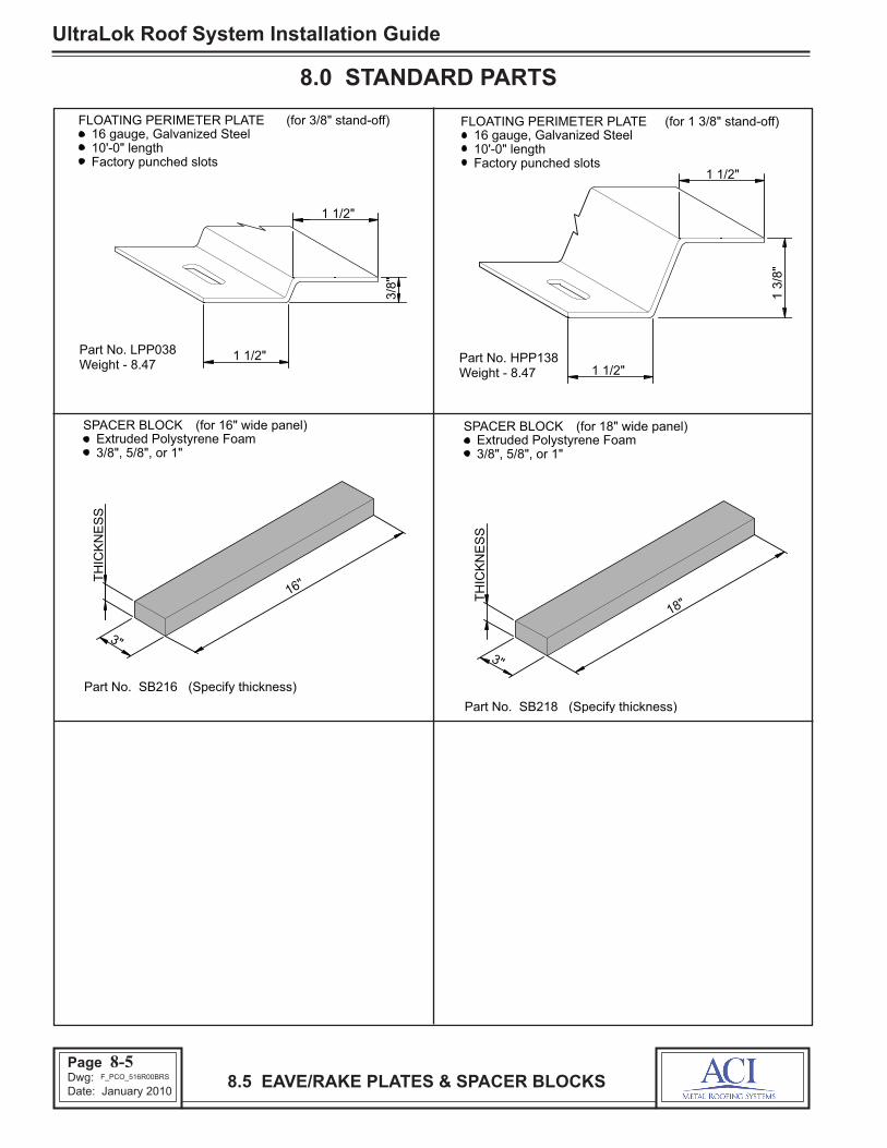
FLOATING PERIMETER PLATE (for 3/8" stand-off)
10'-0" length 16 gauge, Galvanized Steel
Part No. LPP038
Factory punched slots
1 1/2"
3/8"
1 1/2"
Weight - 8.47
FLOATING PERIMETER PLATE (for 1 3/8" stand-off) 16 gauge, Galvanized Steel 10'-0" length
Part No. HPP138
Factory punched slots1 1/2"
1 1/2"
1 3/
8"
Weight - 8.47
SPACER BLOCK (for 16" wide panel)
3/8", 5/8", or 1" Extruded Polystyrene Foam
Part No. SB216 (Specify thickness)
16"
3"
TH
ICK
NE
SS
SPACER BLOCK (for 18" wide panel)
3/8", 5/8", or 1" Extruded Polystyrene Foam
18"
3"
TH
ICK
NE
SS
Part No. SB218 (Specify thickness)
8-5

Page 21Dwg: Date: January 2010
UltraLok Roof System Installation Guide
8.0 STANDARD PARTS
8.6 FASTENERS8-6
CLIP FASTENER
1/4"-14 x 1 1/4", hex head, Self Drilling Screw Corrosion resistant plating
Part No. CF1
1/4"-14 Thread
(TEK 3)Drill Point
3/8" HexHead
(for panel clip & eave plate attachment to steel purlins)
1 1/4"
CLIP FASTENER
Part No. PW3 (Specify length)
#10-12, Phillips drive, Pan Head Screw Corrosion resistant coating
Length
Phillip Drive
#10-12 Thread
Head Type A Point
(for panel clip attachment to wood decking)
CLIP FASTENER
Part No. MD2 (Specify length)
#12-13, Phillips drive, Truss Head Screw Corrosion resistant coating
#12-13 Thread
Phillips Drive Head
Type AB Point
(for panel clip attachment to metal decking)
Length
SHOULDER FASTENER
Unthreaded Shoulder
(for floating rake plate attachment to
1/4"-14 Thread
1 1/4"
1/4"-14 x1 1/4", hex head, Self Drilling Screwsteel purlins)
3/8" Hex
Shoulder feature Corrosion resistant plating
Part No. SF1
Head Drill Point(TEK 3)
ROOF FASTENER
Part No. 1E (Specify finish)
Corrosion resistant coating or alloy head
(for panel edge and endlap attachment)
EPDM Sealing Washer
Painted or mill finished head
Backer Washer Sealing Washer
#12-14 Thread
5/16" Hex Head Drill Point
(TEK 3)
1 1/4"
#12-14 x 1 1/4", hex head, Self Drilling Screw
LAP FASTENER
Part No. LT4 (Specify finish)
Corrosion resistant coating or alloy head
1/4"-14 x 7/8", Self Drilling Screw EPDM Sealing Washer
Painted or mill finished head
7/8"
Backer Washer Sealing Washer
1/4"-14 Thread
5/16" Hex Head Drill Point
(TEK 1)
(for flashing attachment)
F_PCO_520R00BRS

UltraLok Roof System Installation Guide
Page 22Dwg: Date: January 2010
8.0 STANDARD PARTS
8.7 FASTENERS & SEALANTSF_PCO_526R00BRS
BLIND RIVET Stainless steel 1/8" dia. x 3/16" length
Part No. PR14
Mandrel
Rivet Body
Head
(for flashing joints) ENDLAP SEALANT
5/32
"
5/32" x 1 1/4" triple bead Butyl Tape Sealant
Part No. TBT
Paper Backing
Sealant 1 1/4"
(for roof panel endlaps)
FLASHING SEALANT
Paper Backing
Sealant
Part No. DBT
3/16" x 7/8" Butyl Tape Sealant
7/8"
3/16
"
(for flashing laps & joints) TUBE SEALANT
Part No. TS
TriPolymer Gun Grade Sealant
1/10 Gal. Tubes Color - Clear
8-7
ROUND WASHER HEAD SCREW• #8 x 1/2" Tracer D.S. Round Head Screws
PANHEAD SCREW• 1/4 - 14 x 1" Panhead Screw

Page 23Dwg: Date: January 2010
UltraLok Roof System Installation Guide
9.0 ROOF INSTALLATION DETAILS
The following details provide graphic illustration of the roof assembly steps. The purpose is to instruct the erection crew in correct and efficient assembly of the roof system.
Because of the many variations in conditions, it is important that you review the job to identify and isolate the specific installation details required for your job.
Review the erection drawings for differences with these details. If differences exist, the erection drawings have precedence.
These details are arranged in a step-by-step sequence. Following this sequence ensures correct assembly and ensures that the part to be worked on will be readily acces-sible for the next assembly step.
Do not shortcut these assembly steps without careful con-sideration of the possibility of incorrect or omitted assembly and the resulting corrective rework.
To minimize confusion, the details are always oriented so that the view is from eave to ridge, with the starting rake at the left and finish rake at the right. Refer to the erection drawings to determine the required sheeting direction and rake conditions.
To help ensure weathertightness, the details emphasize proper fit-up, sealing and fastening. It is most important that only the specified sealants and fasteners be used for each condition and that they be installed correctly as shown on these details and the erection drawings.
Be sure that these critical instructions are reviewed often and the roof assembly is checked at each assembly step.
9.1 GENERAL
ROOF INSTALLATION DETAILS9-1

UltraLok Roof System Installation Guide
Page 24Dwg: Date: January 2010
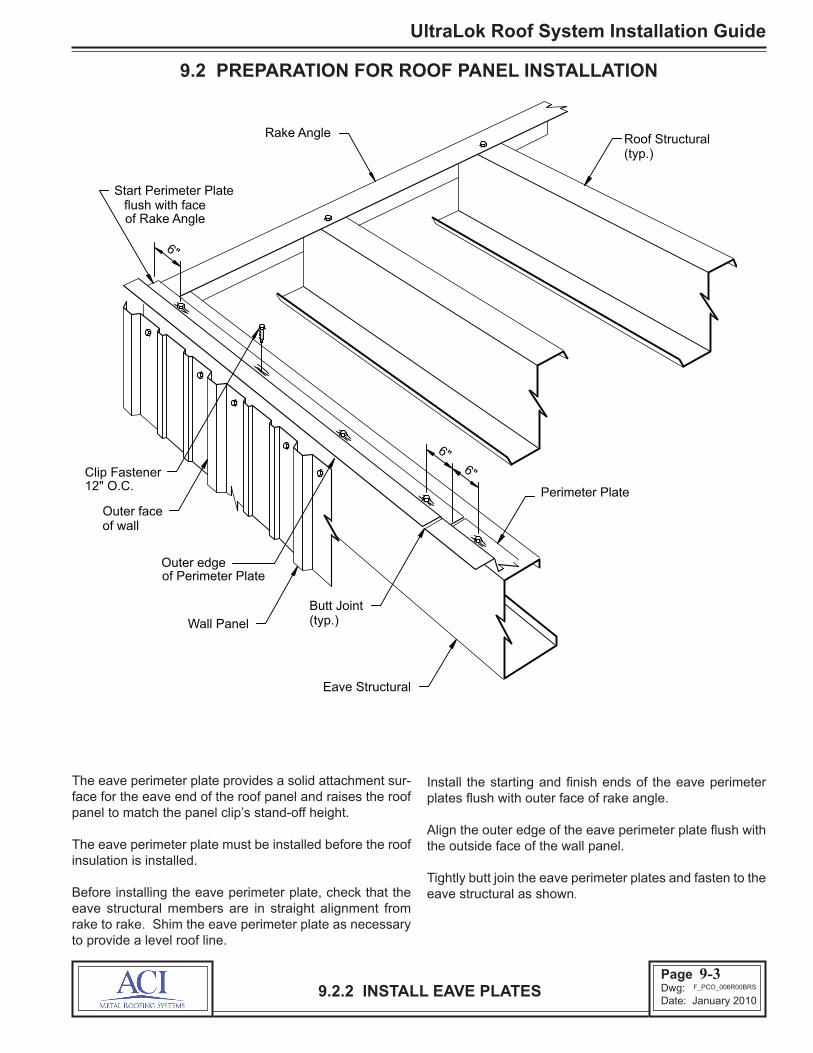
9.2 PREPARATION FOR ROOF PANEL INSTALLATION
The details in this section will show installation of the eave perimeter plate, rake perimeter plate, start clips, eave trim, eave sealant and the first run of insulation. These are parts that must be installed before the roof panel installation can begin.
This view shows the roof system oriented for a left-to-right sheeting direction. For right-to-left sheeting, reverse the parts orientation.
9.2.1 ORIENTATION VIEW
On this view, the starting rake is shown with starting clips (for a starting panel) and the finish rake is shown with a rakeperimeter plate (for a termination panel). Some buildings may require a rake perimeter plate at the starting rake. Refer to the erection drawings for the required rake condi-tions.
Rake AngleEave Structural
Perimeter Plate
Rake Angle
Eave Trim
Starting Clips (typ.)
Ridge Roof Structural
Roof Structurals (typ.)
SHEETING DIRECTION
Insulation Starting Run
Perimeter Plate
Rake Angle
9-2F_PCO_005R00BRS
Page 25Dwg: Date: January 2010
UltraLok Roof System Installation Guide
9.2 PREPARATION FOR ROOF PANEL INSTALLATION
The eave perimeter plate provides a solid attachment sur-face for the eave end of the roof panel and raises the roof panel to match the panel clip’s stand-off height.
The eave perimeter plate must be installed before the roof insulation is installed.
Before installing the eave perimeter plate, check that the eave structural members are in straight alignment from rake to rake. Shim the eave perimeter plate as necessary to provide a level roof line.
9.2.2 INSTALL EAVE PLATES
Install the starting and finish ends of the eave perimeter plates flush with outer face of rake angle.
Align the outer edge of the eave perimeter plate flush with the outside face of the wall panel.
Tightly butt join the eave perimeter plates and fasten to the eave structural as shown.
Eave Structural
Outer edge
Wall Panel
Butt Joint (typ.)
Start Perimeter Plate flush with face
of wall Outer face
6"
6" 6"
Roof Structural (typ.)
Rake Angle
Clip Fastener 12" O.C.
of Rake Angle
of Perimeter Plate
Perimeter Plate
9-3F_PCO_006R00BRS

UltraLok Roof System Installation Guide
Page 26Dwg: Date: January 2010
9.2 PREPARATION FOR ROOF PANEL INSTALLATION
The appropriate height fixed clips are used as start clips.
Refer to the erection drawings and the structural layout (as described in Section 6.2) to determine the start dimen-sion.
The position of the start clips establishes the starting roof panel alignment. It is very important that the start clips are installed in a straight line, parallel to the rake line.
If the rake angles have been installed true and square, the edge of the rake angle can be used to align the start clips.
If the rake angle is not true and square, a chalk line should be used to guide the installation of the start clips.
Locate the start clips at the spacing shown and fasten to the rake angle as shown.
9.2.3 INSTALL START CLIPS
Eave Structural
12"
StartClip
Clip Fastener
24" O.C.
(typ.)Roof Structural
Rake Angle
NOTERefer to erection drawingsfor structural fastener type and quantity
(2) per clip
PerimeterPlate
9-4F_ULO_007R00ACI

Page 27Dwg: Date: January 2010
UltraLok Roof System Installation Guide
9.2 PREPARATION FOR ROOF PANEL INSTALLATION
Set the eave trim over the eave perimeter plate as shown and align the face of the eave trim with the face of the wall panel.
Install the starting and finish ends of the eave trim flush with the ends of the eave perimeter plate.
The eave trim provides a water seal between the roof panel
and the wall panels. All laps of the eave trim must be sealed with tube sealant and rivets as shown to minimize water entry.
Fasten each piece of eave trim to the eave plate with #8 x 1/2" screws at 5'-0" o/c. The screws will hold the trim in position until the roof panels are installed and fastened.
9.2.4 INSTALL EAVE TRIM
Starting Eave Trim
Wall Panel
of Rake AngleTrim flush with face
Start & finish Eave
Perimeter Plate
Rake Angle
Eave Trim Splice
Blind Rivet1/8" dia.
TrimEave
21 "
Tube Sealant3/16" dia. x 1"
Pigtail
Tube Sealant3/16" dia.
Eave Trim
121 "
2" lap
Eave Trim
Eave Trim
#8 x 1/2"screws @5'-0" o.c. foreave trim toperimeterplate attachment.
9-5F_ULO_008R00ACI

UltraLok Roof System Installation Guide
Page 28Dwg: Date: January 2010
Apply a continuous strip of flashing sealant along the top edge of the eave trim.
Align the outer edge of the sealant flush with the outer edge of the eave trim.
Do not remove the paper backing from the sealant at this time.
9.2.5 INSTALL EAVE SEALANT
Until the roof panels are installed, the eave sealant is vulner-able to damage from foot traffic or dragging material over the eave. Do not step on or otherwise damage the sealant.
9.2 PREPARATION FOR ROOF PANEL INSTALLATION
Rake Angle
Eave Trim
Flashing Sealant (set flush withouter edge of eave trim)
Extend sealant 1/2" beyond end of Eave Trim
Outer edge of Eave Trim
9-6F_PCO_009R00BRS

Page 29Dwg: Date: January 2010
UltraLok Roof System Installation Guide
9.2 PREPARATION FOR ROOF PANEL INSTALLATION
Refer to the erection drawings to determine the specific insulation required for the project. In all cases refer to the insulation manufacturer’s instructions for proper insulation installation and vapor seal assembly. This detail shows fiberglass blanket insulation, which is the most commonly used insulation for metal standing seam roofs.
The leading edge of each insulation run should extend approx. 12” beyond the leading edge of the roof panel. This will allow for easy assembly of the vapor barrier seal between insulation runs.
With four foot or six foot wide insulation, the first run should be installed to only cover three feet or five feet respec-tively.
The extra foot of width can be cut or lapped over the rake.
Use double-faced tape along the backside of the eave strut and along the rake angle to hold the insulation in place until the roof panel is installed.
In high wind areas or when using high stand-off clips, use metal insulation retainer straps to secure the insulation to the low flange of the eave perimeter plate. In all cases, do not extend the end of the insulation onto the high flange of the eave plate.
9.2.6 INSTALL STARTER RUN OF INSULATION9-7
Note: Insulation clamping strap and fasteners are not provided with roof system
#12 Fastener
Insulation End of
Optional Insulation
Edge of Insulation
Eave Structural Perimeter Plate
Barrier Tab Insulation Vapor
Roof Structural
Start Clip (typ.)
Clamping Strap
(typ.)
Step of Perimeter Plate
(set behind step of eave plate)
Roof Insulation (starting run)
Starter Width @ 12" O.C.
(lapped or cut flush with face of rake angle)
F_PCO_010R00BRS
UltraLok Roof System Installation Guide
Page 30Dwg: Date: January 2010
9.3 ROOF PANEL INSTALLATION
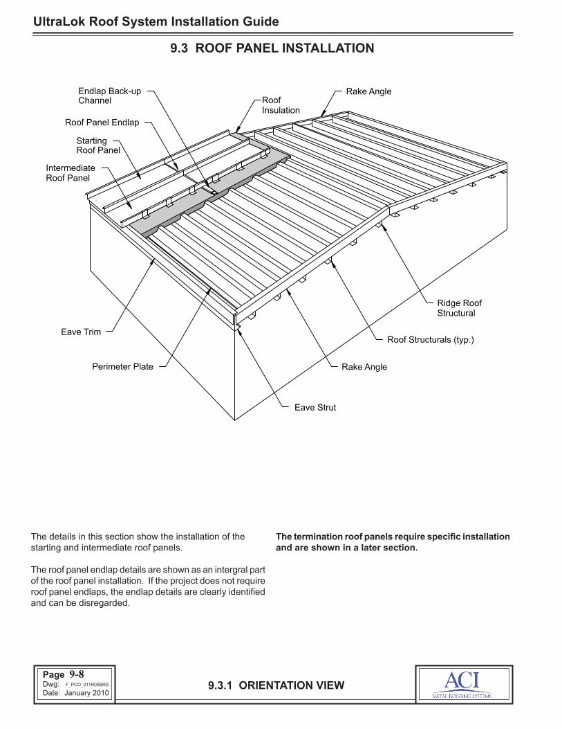
The details in this section show the installation of the starting and intermediate roof panels.
The roof panel endlap details are shown as an intergral part of the roof panel installation. If the project does not require roof panel endlaps, the endlap details are clearly identified and can be disregarded.
The termination roof panels require specific installation and are shown in a later section.
9.3.1 ORIENTATION VIEW
Eave Strut
Roof Structurals (typ.)
Rake Angle
Ridge Roof Structural
Roof Panel Endlap
Starting Roof Panel
Intermediate Roof Panel
Rake Angle
Insulation Roof
Perimeter Plate
Eave Trim
Endlap Back-up Channel
9-8F_PCO_011R00BRS

Page 31Dwg: Date: January 2010
UltraLok Roof System Installation Guide
9.3 ROOF PANEL INSTALLATION
Throughout these instructions, the references to the panel will be made using the terms shown on the above illustration.
Roof panels may be sheeted in either direction, (left-to-right) or (right-to-left). Check the erection drawings and job conditions to determine if the roof must be sheeted in a specific direction.
The leading edge of the roof panel is the edge towards the sheeting direction. On the ACI Metal Roofing Systems roof panel, the male seam is the always the leading edge.
Before loading the panels onto the roof structurals, orient the panels so that the male seam is the leading edge.
* Striations not shown throughout remainder of text for clarity.
9.3.2 ROOF PANEL DESCRIPTION & NOMENCLATURE
9-9
PANEL SECTION
16", or 18"
Panel Length
Panel Width
16" or 18"
Factory Notch
2"
in the seam)
Seam Sealant(factory applied
Female Seam
of panel)(trailing edge
Pan
5/8"
Seam Sealant
Female Seam
Male Seam
Panel Width
115 16"
3/4"
2" Factory Notch
2"
Factory Notch
Pan
of panel)(leading edgeMale Seam
2"
Factory Notch
*
2"
Factory Notch
2"Factory Notch
Detail "1"
Detail "2"
Detail "1" Detail "2"
17 8"
F_ULO_012R02ACI

UltraLok Roof System Installation Guide
Page 32Dwg: Date: January 2010
9.3 ROOF PANEL INSTALLATION
The roof panel’s eave overhang dimension is critical as it establishes the location of endlaps and ridge cover attach-ment points.
The end of the roof panel extends 2” beyond the face of the eave trim unless another dimension is specified on the erection drawings.
If insulation spacer blocks are required, place the blocks on top of the insulation directly over the roof structurals. Spacer blocks are not required at the eave structural.
Position the female edge of the panel over the start clips and position the end of the panel 2” beyond the face of the eave trim.
Tilt the panel as shown so the female seam can be hooked over the start clips. Check that each clip is hooked inside of the seam.
Do not completly remove the eave sealant’s protective paper at this time
9.3.3 INSTALL STARTING ROOF PANEL
Downslope
Roof Panel end of
Male Seam
Roof Structural
Eave Structural
(typ.)
Female Seam
Roof Insulation
Eave Sealant's Protective Paper (peel back only enough
Roof Panel
to set panel)
Start Clip (typ.)
hook the female seam Tilt the Roof Panel to
onto the Start Clip
@ each purlin, Spacer Block
if required
Eave Trim
PANEL OVERHANG
of Eave TrimOuter face
Wall Panel
Downslopeend ofRoof Panel
2"
Eave Structural
Roof Panel
9-10F_PCO_013R00BRS

Page 33Dwg: Date: January 2010
UltraLok Roof System Installation Guide
9.3 ROOF PANEL INSTALLATION
Verify that the roof panel’s overhang dimension is correct and verify that the roof panel is aligned parallel to the rake line. Raise the leading corner of the panel and remove the protective paper from the eave sealant.
Rotate the panel down to rest on the spacer blocks or insulation.
Using the manual seaming tool, close the panel seam over each start clip. For proper operation of the seaming tool, refer to the Seaming Instructions section.
Mark the roof panel’s vertical leg at each clip location. This will guide the later installation of the rake trim fasteners to ensure they are not installed through the start clip tabs.
9.3.4 SEAM ROOF PANEL TO START CLIPS
Downslopeend ofRoof Panel
Eave Structural
2"
Roof Structural(typ.)
of each Start ClipMark the location
(typ.)Start Clip
Roof Panel
Roof Insulation
Spacer Block(typ.)Use manual seaming
tool to close seamat each start clip
9-11F_ULO_014R00ACI
UltraLok Roof System Installation Guide
Page 34Dwg: Date: January 2010
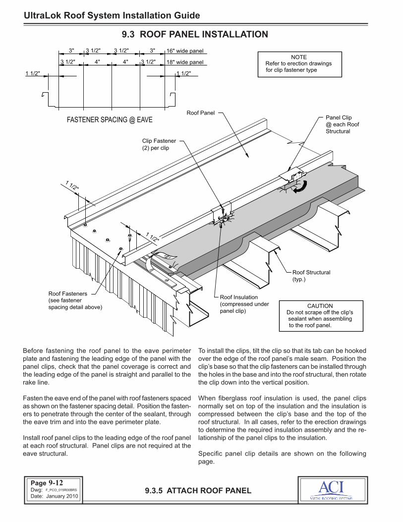
Before fastening the roof panel to the eave perimeter plate and fastening the leading edge of the panel with the panel clips, check that the panel coverage is correct and the leading edge of the panel is straight and parallel to the rake line.
Fasten the eave end of the panel with roof fasteners spaced as shown on the fastener spacing detail. Position the fasten-ers to penetrate through the center of the sealant, through the eave trim and into the eave perimeter plate.
Install roof panel clips to the leading edge of the roof panel at each roof structural. Panel clips are not required at the eave structural.
9.3.5 ATTACH ROOF PANEL
To install the clips, tilt the clip so that its tab can be hooked over the edge of the roof panel’s male seam. Position the clip’s base so that the clip fasteners can be installed through the holes in the base and into the roof structural, then rotate the clip down into the vertical position.
When fiberglass roof insulation is used, the panel clips normally set on top of the insulation and the insulation is compressed between the clip’s base and the top of the roof structural. In all cases, refer to the erection drawings to determine the required insulation assembly and the re-lationship of the panel clips to the insulation.
Specific panel clip details are shown on the following page.
9.3 ROOF PANEL INSTALLATION
NOTE
FASTENER SPACING @ EAVE
CAUTION
Roof Panel
Roof Structural
Roof Insulation
(typ.)
(compressed under panel clip)
(2) per clip Clip Fastener
Structural @ each Roof Panel Clip
Refer to erection drawings for clip fastener type
Roof Fasteners
1 1/2"
1 1/2"
spacing detail above)
3 1/2" 4" 4" 3 1/2"
3" 3 1/2" 3 1/2" 3"
1 1/2" 1 1/2"
16" wide panel
18" wide panel
(see fastener
to the roof panel. sealant when assembling
Do not scrape off the clip's
9-12F_PCO_015R00BRS

Page 35Dwg: Date: January 2010
UltraLok Roof System Installation Guide
9.3 ROOF PANEL INSTALLATION
9.3.6 PANEL CLIP DETAILS
Panel clips are available as floating clips or fixed clips and are available in different stand-off heights. Refer to the erection drawings to determine the type of clip and quantity of fasteners required for each roof condition.
Check that the panel clip’s tab is seated tightly around the roof panel’s seam.
Check that the clip’s base is vertical and that the base is set square and firmly over the roof structural.
Panel clip fastener type and quantity vary according to the roof structural material and roof load requirements. Refer to the erection drawings for the required type and quantity of panel clip fasteners.
Check that the clip fasteners are equally spaced through the clip base holes and are securely engaged into roof structural.
CLIP TO PANEL ASSEMBLY
Insulation not shownNote:
Roof Structural
Clip Fastener
Clip Base
against panel)(must be flushClip Tabon panel)
(must set flushClip Tab Hook
Roof Panel
Clip Tab
Clip Base
Roof Structural
StopsBase Centering
Clip Fastener(2 per clip min.)
Roof Panel
Panel Shelf
Panel Shelf(roof panel mustset on top of stop)
CAUTIONFailure to fully nest the clip flush
against the panel can causefaulty seaming and objectionable
seam appearance.
for clarity.
See erection drawingsfor no. of clip screws req'd.
(2 per clip min.)
9-13F_PCO_016R00BRS

UltraLok Roof System Installation Guide
Page 36Dwg: Date: January 2010
9.3 ROOF PANEL INSTALLATION
With the eave end of the roof panel attached, measure the panel overhang at the endlap roof structural (see illustra-tion).
The panel should extend 6” beyond the web of the roof structural.
9.3.7 ENDLAP — VERIFY PANEL OVERHANG
If the panel overhang is not 6", call ACI Metal Roofing Systems before proceeding with the installation of roof panels. Also reference the erection drawings for prescribed dimensions.
9-14
PANEL OVERHANG
(@ the endlap) Roof Structural
Panel Clip (typ.)
Downslope Roof Panel
Roof Insulation
6" End ofPanelStructural
Web of Roof
Roof Panel
Roof Structural(@ the endlap)
F_PCO_017R00BRS

Page 37Dwg: Date: January 2010
UltraLok Roof System Installation Guide
9.3 ROOF PANEL INSTALLATION
9.3.8 ENDLAP — INSTALL ENDLAP SEALANT
The proper placing of the endlap sealant is critical to the weathertightness of the roof endlaps.
Before installing the endlap sealant, the roof panel’s surface must be wiped clean and dry.
Position the sealant so that its downslope edge is uniformly 1 5/8” from the end of the panel.
Install a continuous strip of endlap sealant along the end of the roof panel as shown.
Check that the sealant fully contacts the roof panel’s surface and that it is completely fitted into the panel corners and around the seams.
The sealant’s protective paper helps to retain the sealant’s shape during installation and protects the sealant’s surface from damage and contamination. Do not remove the pro-tective paper until immediately before the installation of the up-slope roof panel.
Specific endlap sealant details are shown on the following page.
(@ the endlap)Roof Structural
Panel Clip(typ.)
Downslope RoofPanel
Roof Insulation
Endlap Sealant
1 5/8"
9-15F_ULO_018R00ACI

UltraLok Roof System Installation Guide
Page 38Dwg: Date: January 2010
9.3 ROOF PANEL INSTALLATION
9.3.9 ENDLAP — SEALANT DETAILS
Cut the endlap sealant to be fitted around the roof panel’s seams as shown.
Check that the 1/8” ends of the sealant are correctly folded around the roof panel’s edges. Excess sealant in the roof panel seams will cause difficult panel assembly. Remove any excess sealant.
After the sealant is correctly positioned, uniformly press the sealant against the roof panel’s surface to assure adhesion. Do not use excess pressure which can thin the sealant.
1 5/8" Endlap Sealant
Roof Panel
Roof Panel
ENDLAP SEALANT @ FEMALE SEAM
Endlap
ENDLAP SEALANT @ MALE SEAMFemaleSeam
1/8" of sealantfolded overedge of panel
1/8" of sealantfolded under edge of panel
Sealant
1 5/8"
Male Seam
Endlap Sealant
9-16F_ULO_019R00ACI

Page 39Dwg: Date: January 2010
UltraLok Roof System Installation Guide
9.3.10 ENDLAP — UP-SLOPE PANEL PLACEMENT
9.3 ROOF PANEL INSTALLATION
Wipe dry and clean the underside surface of the up-slope roof panel.
Remove the protective paper from the installed endlap sealant.
Position the end of the up-slope roof panel to make a 2” lap over the downslope roof panel.
At the seams, the end of the up-slope roof panel should butt against the notch on the downslope roof panel.
Check that the up-slope roof panel will correctly lap over the endlap sealant.
(@ endlap) Roof Structural
Panel Clip (typ.)
Downslope Roof Panel
Up-slope Roof Panel
Butt end of Panel against end of notch to make 2" lap
Endlap
Roof Insulation
Sealant
Backup Channel notshown for clarity
9-17F_PCO_020R00BRS

UltraLok Roof System Installation Guide
Page 40Dwg: Date: January 2010
9.3.11 ENDLAP — PANEL ALIGNMENT
9.3 ROOF PANEL INSTALLATION
Lower the up-slope roof panel to lap onto the downslope roof panel.
While lowering the upslope roof panel, bow the end of the panel by pulling up on its center. This will allow the panel to more easily nest into the down-slope panel.
Do not displace or damage the sealant while nesting the up-slope panel.
Backup Channel notshown for clarity
Caution
Roof Structural (typ.)
Roof Panel Downslope
Insulation Roof
Upslope Roof Panel
Pull up center of panel
Sealant Endlap
Panel Clip
While setting the roof panel, Do not wipe the endlap sealant off the sides of the panel.
9-18F_PCO_021R00BRS

Page 41Dwg: Date: January 2010
UltraLok Roof System Installation Guide
9.3.12 ENDLAP — CLAMP THE SEAMS
9.3 ROOF PANEL INSTALLATION
Use the seam clamps to draw the lapping panel seams together as shown.
Check that the clamp jaws are correctly aligned to the seam before closing the clamp. Misaligned clamps can distort and damage the roof panel seams.
Slowly close the clamp to allow the sealant to flow between the lapped seams.
With the seam clamps installed, uniformly press down on the up-slope panel to close the panel lap and to assure adhesion to the endlap sealant.
9-19
Back-up Channel
CLAMPED SEAM
Roof Panel
Seam Clamp
Endlap
Seam clamp (center over the seam notch)
Seam Clamp (center over the seam notch)
Downslope Roof Panel
Panel Clip (typ.) Roof structural (@ the endlap)
Roof Insulation
Upslope Roof Panel
F_PCO_022R00BRS

UltraLok Roof System Installation Guide
Page 42Dwg: Date: January 2010
Field cut the starting back-up channel. Cut the channel’s length equal to the width of the starting run of roof insula-tion. The cut-off must be the end opposite of the swagged end.
Slide the channel under the roof panel and on top of the roof insulation. Position the channel so its cut end rests on the rake angle and is flush with the face of the rake angle.
Position the channel so it is centered under the roof panel endlap.
9.3.13 ENDLAP — START BACK-UP CHANNELAT RAKE
9.3 ROOF PANEL INSTALLATION
Check that the swagged end of the channel is flush with the leading edge of the roof insulation.
Clamp the channel to the leading edge of the roof panel. Position the clamp at the edge of the channel, so the clamp will not interfere with the installation of the cinch strap.
Check that the clamp is bearing on the flat of the roof panel, not on the panel’s shoulder rib.
Field cut end of
(flush with faceback-up channel
StartingRoof Panel
STARTING RAKE DETAIL
Back-up Channel
Rake Angleof rake angle)
Back-up Channel
Swagged end of channel(flush with edge of insulation)
Roof Insulation(starting run)
StartingRoof Panel
Shoulder Rib
Start Clip(typ.)
Field cut end of channel(flush with face of rake angle)
Rake Angle
Roof Structural(typ.)
Endlap
Clamp
Seam Clamps Not Shown For Clarity
9-20F_ULO_023R00ACI

Page 43Dwg: Date: January 2010
UltraLok Roof System Installation Guide
9.3.14 ENDLAP — INSTALL CINCH STRAP
9.3 ROOF PANEL INSTALLATION
A cinch strap is not required on all roof applications. Refer to the erection drawings to determine if a cinch strap is required.
If a cinch strap is required, carefully position the cinch strap over the endlap.
Install roof fasteners in the holes at each end of the cinch strap. Then install fasteners in the remaining holes.
If cinch strap is not required, refer to the erection drawings for lap screw requirements.
Check that the roof fasteners penetrate thru the center of the endlap sealant and are securely engaged into the back-up channel.
Hand seam end lap, refer to seaming guide for specific steps.
STEP 1 STEP 2
Upslope Roof Panel
Endlap
Downslope Roof Panel
Roof structural (@ the endlap)
Roof Insulation
Endlap Fastener @ each hole in Cinch Strap
Cinch Strap,(align strap holeswith center of endlap sealant below)
Seaming Tool
Roof Panel
Seaming Tool
3"
Endlap Endlap Roof Panel
9-21F_PCO_024R00BRS
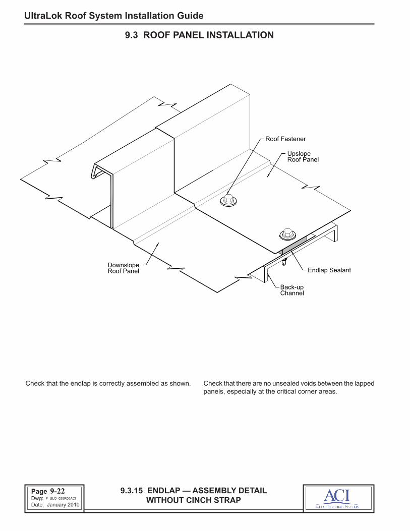
UltraLok Roof System Installation Guide
Page 44Dwg: Date: January 2010
9.3.15 ENDLAP — ASSEMBLY DETAIL WITHOUT CINCH STRAP
9.3 ROOF PANEL INSTALLATION
Check that the endlap is correctly assembled as shown. Check that there are no unsealed voids between the lapped panels, especially at the critical corner areas.
9-22
Roof PanelDownslope
Roof PanelUpslope
Back-upChannel
Endlap Sealant
Roof Fastener
F_ULO_025R00ACI

Page 45Dwg: Date: January 2010
UltraLok Roof System Installation Guide
9.3.16 INSTALL PIGTAIL SEALANTS
9.3 ROOF PANEL INSTALLATION
The pigtail sealants must be correctly installed before the next roof panel run can be installed.
Install the eave, endlap and ridge pigtail sealants on the leading edge of the roof panel as shown.
The pigtail sealants are pieces of flashing sealant cut to the required length.
Refer to the next pages for specific pigtail sealant details.
9-23
Panel Clip (typ.)
Roof Insulation
Eave Structural
Roof Structural (typ.)
Upslope Roof Panel
Downslope Roof Panel
Back-up Channel
Eave Pigtail Sealant
Endlap Pigtail Sealant
Ridge Pigtail Sealant
F_PCO_026R00BRS
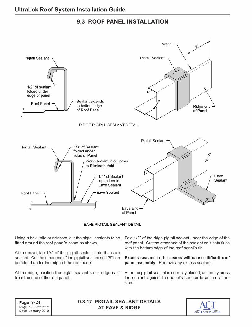
UltraLok Roof System Installation Guide
Page 46Dwg: Date: January 2010
9.3.17 PIGTAIL SEALANT DETAILS AT EAVE & RIDGE
9.3 ROOF PANEL INSTALLATION
Using a box knife or scissors, cut the pigtail sealants to be fitted around the roof panel’s seam as shown.
At the eave, lap 1/4” of the pigtail sealant onto the eave sealant. Cut the other end of the pigtail sealant so 1/8” can be folded under the edge of the roof panel.
At the ridge, position the pigtail sealant so its edge is 2” from the end of the roof panel.
Fold 1/2” of the ridge pigtail sealant under the edge of the roof panel. Cut the other end of the sealant so it sets flush with the bottom edge of the roof panel’s rib.
Excess sealant in the seams will cause difficult roof panel assembly. Remove any excess sealant.
After the pigtail sealant is correctly placed, uniformly press the sealant against the panel’s surface to assure adhe-sion.
9-24
RIDGE PIGTAIL SEALANT DETAIL
EAVE PIGTAIL SEALANT DETAIL
Pigtail Sealant 1/8" of Sealant
1/4" of Sealant lapped on to Eave Sealant
folded under edge of Panel
Ridge end of Panel
folded under 1/2" of sealant
Roof Panel
Sealant Eave
Pigtail Sealant
Sealant extends to bottom edge of Roof Panel
edge of panel
Pigtail Sealant
Notch 2"
Pigtail Sealant
Eave End of Panel
Roof Panel Eave Sealant
Work Sealant into Corner to Eliminate Void
F_PCO_027R00BRS

Page 47Dwg: Date: January 2010
UltraLok Roof System Installation Guide
9.3.18 PIGTAIL SEALANT DETAILAT ENDLAP
9.3 ROOF PANEL INSTALLATION
Using a box knife or scissors, cut the pigtail sealant to a 3” length and fit around the roof panel’s seam as shown.
Position the pigtail sealant to lap 1/2” beyond each end of the roof panel’s notch.
Center the sealant over the roof panel’s seam. Fold the edges of the sealant down over the sides of the seam.
Excess sealant in the seams will cause difficult roof panel assembly. Remove any excess sealant.
After the pigtail sealant is correctly placed, uniformly press the sealant against the panel’s surface to assure adhe-sion.
9-25
3"
Upslope Roof Panel
Pigtail Sealant
1/2"
1/2"
Endlap
End of
1/4" of sealant extended down each side of panel rib
Pigtail Sealant
End of Notch
Downslope Roof Panel
Roof Panel
Notch
Sealant
F_PCO_028R00BRS

UltraLok Roof System Installation Guide
Page 48Dwg: Date: January 2010
9.3.19 INSTALL BACK-UP CHANNEL
9.3 ROOF PANEL INSTALLATION
Install the next run of roof insulation.
Set the next back-up channel on top of the roof insulation. Position the channel so its non-swagged end laps over the swagged end of the previously installed channel. Check that the channel ends and their alignment dimples are fully nested together.
Position the channel’s swagged end so the channel will be centered and parallel to the next roof panel endlap.
Secure the back-up channels together with a panel clip fastener installed through the factory punched hole in the alignment dimple of the overlapping channel. Check that the fastener fully engages the underlying channel.
9-26
LAP DETAIL
Back-up Channel
Back-up
Alignment
Previously installed Back-up
Channel
Dimple
Channel
fastener holeAlign Dimple with
Roof Structural
Insulation Roof
Roof Insulation Previously installed
(typ.)
Dimple Alignment
Swaged end
Roof Panel installed Previously
Back-up Channel Lap joint
(CF1) Panel Clip Fastener
Fastener Panel Clip
F_PCO_029R00BRS

Page 49Dwg: Date: January 2010
UltraLok Roof System Installation Guide
9.3.20 INSTALL NEXT INTERMEDIATE PANELS
9.3 ROOF PANEL INSTALLATION
Remove the protective paper from the eave sealant. Re-move only enough of the protective paper to allow installa-tion of the next roof panel.
If required, place the insulation spacer blocks on top of the insulation directly over the roof structural.
Position the trailing edge of the roof panel over the leading edge of the previously installed roof panel and position the end of the roof panel 2” beyond the face of the eave trim.
Tilt the panel as shown so the female seam can be hooked over the male seam of the previous roof panel.
Specific roof panel sidelap assembly details are shown on the following page.
9-27
Roof Insulation
previously
Roof Panel installed
seam of Male
Seam Female
Roof Structural (typ.) Eave Structural
Roof Panel @ each purlin, Spacer Block
if required
Panel Clip (typ.)
Tilt the Roof Panel to hook the female seam onto the male seam of the previously installed panel
Previously installed Roof Panel / Run
F_PCO_030R00BRS

UltraLok Roof System Installation Guide
Page 50Dwg: Date: January 2010
9.3.21 PANEL SIDELAP ASSEMBLY
9.3 ROOF PANEL INSTALLATION
It is easier to hook the roof panel seams together if the roof panel is first tilted up to the vertical position.
With the roof panel in the vertical position, align its female seam to slide under the male seam of the previous roof panel.
With the female seam under the male seam, lift up the roof panel so the female seam’s hook catches the lip of the male seam.
While continuing to lift up on the roof panel, rotate the panel down to rest on the insulation or spacer blocks.
IMPORTANT: Check that the female hook has enclosed the male lip along the entire length of the roof panel. If not, the roof panel sidelap must be correctly reas-sembled before installing the next roof panel.
9-28
STEP 3
STEP 1
CAUTION
STEP 2
Engaged Seam
under lip of
female hookenclosed by the lip is fully Check that male
male seam
vertical positionTilt panel 90˚ to
Female Seam
female seam Push hook of
Male Seam
the sidelap assembly.seam sealant during
Do not scrape off
rotate over male seamfemale seam to readily Lift panel to allow
catches male female hook Lift panel so
lipto horizontal positionRotate panel down
12
3
F_PCO_031R01BRS

Page 51Dwg: Date: January 2010
UltraLok Roof System Installation Guide
9.3.22 CONTROL PANEL COVERAGE
The most common coverage error is the spreading of the roof panel sidelaps, especially at the panel ends. This can cause excess panel coverage along the eave, endlaps and ridge.
Before installing the next run of panel clips, use rib clamps to squeeze together the previous sidelap as shown.
The rib clamps can be adjusted and locked so that they will squeeze the panel ribs to provide a consistent cover-age width.
If excessive coverage has accumulated over several panel runs, do not try to correct all of the error at one time. Cor-rected roof panel coverage must not be greater than 1/16” per panel. Correct accumulated coverage error by mak-ing the correction over several panel runs. Continue this sheeting process until the opposite end of the building is reached. End dams should be installed as the sheeting process continues.
9.3 ROOF PANEL INSTALLATION
9-29
RIB CLAMP DETAIL Rib Clamp
Eave Structural
Endlap
Roof Structural (typ.)
Rib Clamp
Clamp Jaws
Roof Panel
Roof Panel
Upslope Roof Panel
Downslope Roof Panel
Roof
Seam
Insulation
Adjustment Screw
Locking Nut
(typ.)
F_PCO_032R00BRS
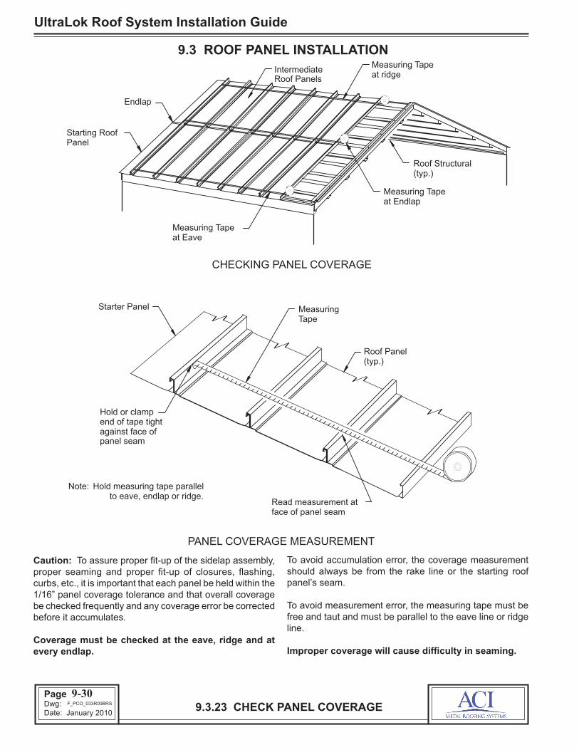
UltraLok Roof System Installation Guide
Page 52Dwg: Date: January 2010
9.3 ROOF PANEL INSTALLATION
9.3.23 CHECK PANEL COVERAGE
Caution: To assure proper fit-up of the sidelap assembly, proper seaming and proper fit-up of closures, flashing, curbs, etc., it is important that each panel be held within the 1/16” panel coverage tolerance and that overall coverage be checked frequently and any coverage error be corrected before it accumulates.
Coverage must be checked at the eave, ridge and at every endlap.
To avoid accumulation error, the coverage measurement should always be from the rake line or the starting roof panel’s seam.
To avoid measurement error, the measuring tape must be free and taut and must be parallel to the eave line or ridge line.
Improper coverage will cause difficulty in seaming.
9-30
PANEL COVERAGE MEASUREMENT
CHECKING PANEL COVERAGE
Note:
(typ.)Roof Structural
Endlap
at EaveMeasuring Tape
Measuring Tapeat ridge
Intermediate
Starter Panel MeasuringTape
(typ.)Roof Panel
Read measurement atface of panel seam
Hold or clampend of tape tightagainst face of
Hold measuring tape parallelto eave, endlap or ridge.
Measuring Tapeat Endlap
Starting RoofPanel
panel seam
Roof Panels
F_PCO_033R00BRS
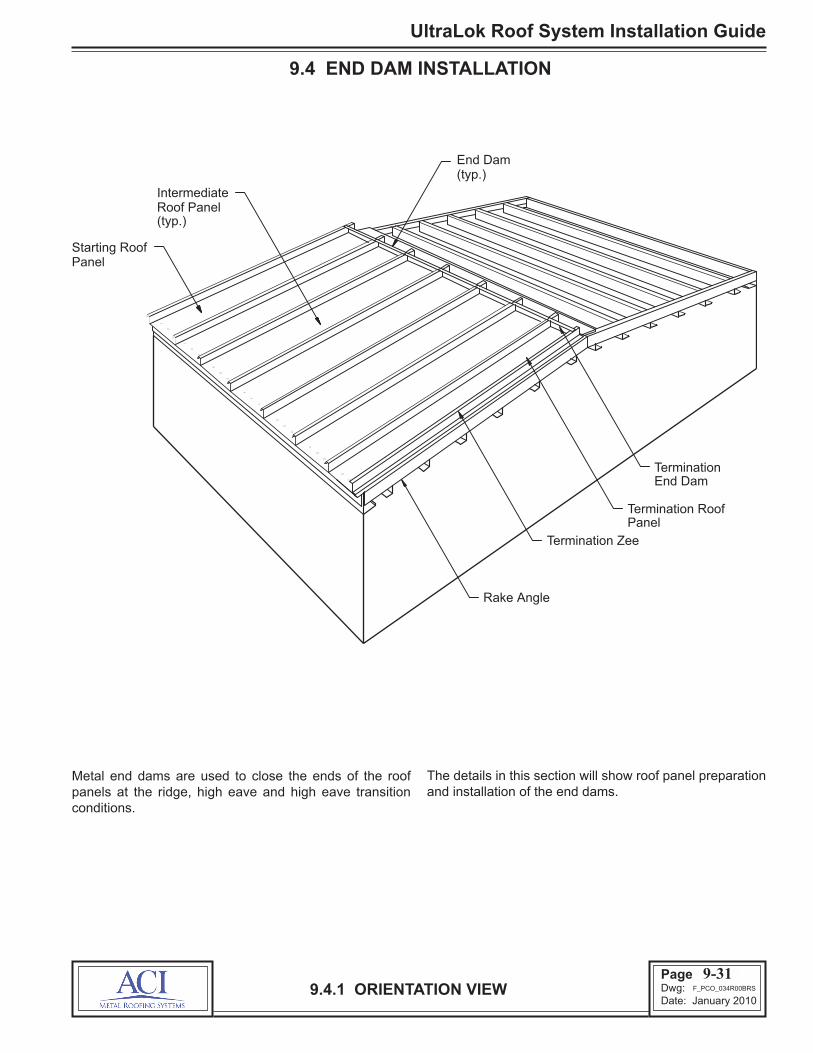
Page 53Dwg: Date: January 2010
UltraLok Roof System Installation Guide
9.4.1 ORIENTATION VIEW
9.4 END DAM INSTALLATION
Metal end dams are used to close the ends of the roof panels at the ridge, high eave and high eave transition conditions.
The details in this section will show roof panel preparation and installation of the end dams.
9-31
Rake Angle
Roof PanelIntermediate
Termination Roof
Termination Zee
Panel
Termination End Dam
End Dam(typ.)
(typ.)
Starting RoofPanel
F_PCO_034R00BRS

UltraLok Roof System Installation Guide
Page 54Dwg: Date: January 2010
9.4.2 PREPARATION FOR END DAM INSTALLATION
9.4 END DAM INSTALLATION
The end dams should be installed before four roof panel runs are completed. Installation of the end dams helps maintain the correct roof panel coverage at the ridge. If the end dams are installed after the roof panels are in place, roof panel coverage error may prevent proper installation of the end dams.
Check the alignment of the roof notches along the ridge. If the notches are staggered more than 1/4”, use a chalk line to establish a straight notch line. Position the chalk line so
no notch extends below the line.
Using the end of the factory notch (or chalk marks) as a guide, field cut the additional notching in both male and female portions of the seam as shown.
Hand seam 16” of uphill panel end before applying tape sealant and end dam to accomodate motor seamer. Refer to seaming guide for specific steps to accommodate motor seamer.
9-32
NOTCH FOR RIDGE CLOSURE
Ridge end ofRoof Panel
Roof Panel
Chalk Mark
Field cut maleand female panelseams, to the chalk mark
Roof Panels
MARKING RIDGE CLOSURE LINE
Ridge end of Roof Panels
2"
Panel Notch(typ.)
Chalk Line
(typ.)Chalk Mark
2"
1/16"
Seaming Tool
Seaming Tool
Eave or RidgeEnd of Roof Panel
Eave or RidgeEnd of Roof Panel
Step 1
6"
Step 2
F_PCO_035R01BRS

Page 55Dwg: Date: January 2010
UltraLok Roof System Installation Guide
9.4.3 INSTALL RIDGE SEALANT
9.4 END DAM INSTALLATION
Before installing the flashing sealant, the roof panel’s sur-face must be wiped clean and dry.
Install a continuous strip of flashing sealant along the end of the roof panel as shown.
Position the sealant so that its downslope edge is uniformly 2” (edge of notch) from the end of the panel.
Be sure to check that the sealant fully contacts the roof panel’s surface and that it is completely fitted into the panel corners and around the seams.
Cut a 2-1/2” long strip of flashing sealant and install as the pigtail sealant as shown.
Specific flashing sealant and pigtail sealant details are shown on the following page.
9-33
Remove protective paper
Ridge end ofRoof Panels
PigtailSealant
Flashing Sealant(downslope edge 2” from end of panel)
2" N
otch
F_PCO_036R00BRS

UltraLok Roof System Installation Guide
Page 56Dwg: Date: January 2010
9.4.4 RIDGE SEALANT DETAILS
9.4 END DAM INSTALLATION
The correct installation of the ridge sealant is critical to the weather resistance of the roof system.
Be sure to verify that the sealant is installed as shown above before installing end dams.
After the sealant is correctly positioned, uniformly press the sealant against the roof panel’s surface to assure adhesion. Do not use excess pressure which can thin the sealant.
9-34
Roof Panel
Roof Panel
FLASHING SEALANT @ RIDGE
over seamSealant wrapped
PIGTAIL SEALANT @ RIDGE
Flashing Sealant
212 " Pigtail Sealant
End of Notch
of Roof PanelRidge end
Flashing Sealant
2"Ensure Sealants make contact
212 " Pigtail Sealant
1 3/4" to 2"
1/2" to 3/4"
Centered on panel leg
F_PCO_037R01BRS

Page 57Dwg: Date: January 2010
UltraLok Roof System Installation Guide
9.4.5 INSTALL END DAMS
9.4 END DAM INSTALLATION
Wipe dry and clean the underside surface of the end dam flanges.
Position the end dam so its bottom flange is turned up-slope and its top flange is downslope.
Position the end dam’s bottom flange directly over the ridge sealant and align the end dam web with the panel notch (2” from end of panel).
Be careful not to displace or damage the sealant while installing the end dam.
9-35
Roof Panel(typ.)
Top flange (must beon downhill side)
End Dam
Flashing Sealant
Pigtail Sealant
F_PCO_038R02BRS
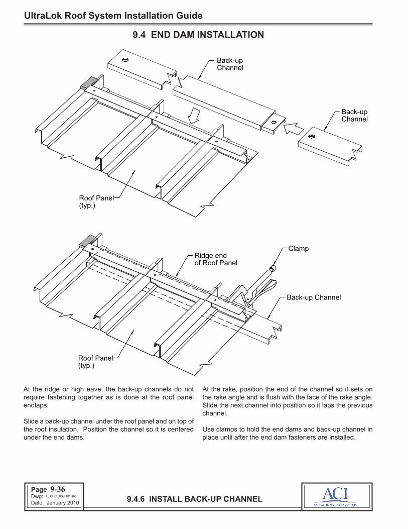
UltraLok Roof System Installation Guide
Page 58Dwg: Date: January 2010 9.4.6 INSTALL BACK-UP CHANNEL
9.4 END DAM INSTALLATION
At the ridge or high eave, the back-up channels do not require fastening together as is done at the roof panel endlaps.
Slide a back-up channel under the roof panel and on top of the roof insulation. Position the channel so it is centered under the end dams.
At the rake, position the end of the channel so it sets on the rake angle and is flush with the face of the rake angle. Slide the next channel into position so it laps the previous channel.
Use clamps to hold the end dams and back-up channel in place until after the end dam fasteners are installed.
9-36
Back-upChannel
Ridge endof Roof Panel
Clamp
Back-up Channel
Roof Panel(typ.)
Roof Panel(typ.)
Back-upChannel
F_PCO_039R01BRS

Page 59Dwg: Date: January 2010
UltraLok Roof System Installation Guide
9.4.7 END DAM ATTACHMENT
9.4 END DAM INSTALLATION
Uniformly press the end dam into the ridge sealant to as-sure adhesion. Use a clamp to hold the assembly together while installing the fasteners.
Install clip fasteners through the holes in the end dam’s bottom flange. Note fastener placement sequence.
Check that the fasteners penetrate through the center of the ridge sealant and are securely engaged into the back-up channel.
Check that the face of the end dam is perpendicular to the
roof panel and aligned with the previously installed end dams. If not, push the top of the end dam to the correct position and clamp.
Install a clip fastener through the hole at the side of the end dam, through the roof panel vertical leg and into the opposite end dam.
Important: Overtightening this fastener will squeeze the roof panel sidelap assembly together and may af-fect the roof panel’s coverage width. Carefully tighten the fastener only as necessary to maintain the correct panel width.
9-37
Roof Panel(typ.)
CF1 Fasteners
Flashing Sealant
End Dam@ each hole inEnd Dam
Back-upChannel
Back-up Channel
End Dam
Clip Fastener (CF1)@ each hole in End Dam
Roof Panel
Flashing Sealant END DAM ATTACHMENT
FastenerCF1 Clip
Clamp
1
243
Sheeting Direction
5
F_ULO_040R01ACI
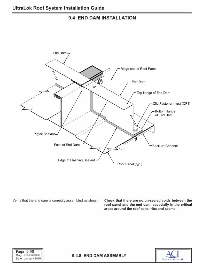
UltraLok Roof System Installation Guide
Page 60Dwg: Date: January 2010
9.4.8 END DAM ASSEMBLY
9.4 END DAM INSTALLATION
Verify that the end dam is correctly assembled as shown. Check that there are no un-sealed voids between the roof panel and the end dam, especially in the critical areas around the roof panel ribs and seams.
Back-up Channel
Roof Panel (typ.)
Pigtail Sealant
Face of End Dam
Edge of Flashing Sealant
End Dam
Top flange of End Dam
Clip Fastener (typ.) (CF1)
End Dam
Ridge end of Roof Panel
Bottom flangeof End Dam
9-38F_ULO_041R01ACI

Page 61Dwg: Date: January 2010
UltraLok Roof System Installation Guide
9.5.1 ORIENTATION VIEW
9.5 TERMINATION PANEL INSTALLATION
The details in this section show the installation of the ter-mination roof panel and the termination zee.
The details show the termination roof panel installed at the
finish rake. The installation of the termination panel at the starting rake is similar.
9-39
Rake Angle
(typ.)
Termination Roof
Perimeter Plate
Termination Zee
Panel
Roof Panel
F_PCO_042R00BRS
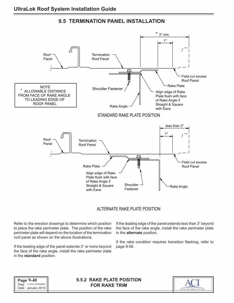
UltraLok Roof System Installation Guide
Page 62Dwg: Date: January 2010
9.5 TERMINATION PANEL INSTALLATION
Refer to the erection drawings to determine which position to place the rake perimeter plate. The position of the rake perimeter plate will depend on the location of the termination roof panel as shown on the above illustrations.
If the leading edge of the panel extends 3” or more beyond the face of the rake angle, install the rake perimeter plate in the standard position.
9.5.2 RAKE PLATE POSITION FOR RAKE TRIM
If the leading edge of the panel extends less than 3” beyond the face of the rake angle, install the rake perimeter plate in the alternate position.
If the rake condition requires transition flashing, refer to page 9-56.
9-40
STANDARD RAKE PLATE POSITION
ALTERNATE RAKE PLATE POSITION
NOTE
Panel Roof Termination
Roof Panel
Field cut excess Roof Panel
Rake Plate
Rake Angle
Rake Plate
Shoulder Fastener
Plate flush with face Align edge of Rake
of Rake Angle if Straight & Square
ALLOWABLE DISTANCE FROM FACE OF RAKE ANGLE
TO LEADING EDGE OF ROOF PANEL
*
*
less than 3"
Roof Panel Termination Roof
Panel
Rake Angle
3" min.
1"
1"
Field cut excess Roof Panel
with Eave
Plate flush with face Align edge of Rake
of Rake Angle if Straight & Square with Eave
Shoulder Fastener
F_PCO_043R00BRS

Page 63Dwg: Date: January 2010
UltraLok Roof System Installation Guide
9.5 TERMINATION PANEL INSTALLATION
It is important that the rake perimeter plate is installed in a straight line and square with the eave.
If the rake angles have been installed straight and true, the edge of the rake angle can be used to align the rake perimeter plate.
If the rake angle is not true and square, a chalk line should be used to guide the installation of the eave perimeter plate.
9.5.3 START RAKE PLATE INSTALLATION AT EAVE
Start the end of the rake plate flush with the outer edge of the eave perimeter plate. Notch the bottom flange of the rake plate to clear the eave plate.
Secure the starting end of the perimeter plate to the rake angle with a clip fastener in the rake plate’s first slot.
To allow for expansion/contraction movement, secure the rest of the rake plate run to the rake angle with shoulder fasteners spaced as shown. Install the shoulder fasten-ers in the center of the slots.
9-41
Rake Angle
Eave Plate
Roof Structural (typ.)
Shoulder Fasteners @ 24" O.C.
Rake Perimeter Plate
Clip Fastener @ first slot from Eave
clear Eave Plate Notch Rake Plate to
Structural Eave
F_PCO_044R00BRS

UltraLok Roof System Installation Guide
Page 64Dwg: Date: January 2010
9.5 TERMINATION PANEL INSTALLATION
Butt join the ends of the rake perimeter plate. Install the shoulder fasteners in the slots on either side of the butt joints.
9.5.4 RAKE PLATE ASSEMBLY AT JOINTS & RIDGE
Field cut the last rake perimeter plate two inches (2”) from the ridge line or high eave line.
9-42
Shoulder Fasteners@ 24" O.C.
Field cut end of Perimeter Plate
Rake Angle
Butt join Perimeter Plates
Perimeter Plate
Ridge2"
Roof Structurals(typ.)
F_PCO_045R01BRS

Page 65Dwg: Date: January 2010
UltraLok Roof System Installation Guide
9.5.5 INSTALL TERMINATION PANEL
9.5 TERMINATION PANEL INSTALLATION
Field cut the termination roof panel to the required width. The cut edge of the panel should extend 1” beyond the outer edge of the rake perimeter plate’s top flange.
Remove the protective paper from the eave sealant.
Install the termination panel into position as shown.
Install the eave fasteners and temporarily clamp the edge of the panel to the rake perimeter plate.
9-43
Clamp
Perimeter Plate
Roof Panel
Roof Fastener
Rake Angle
Field cut edge of Termination Panel
Termination Roof Panel
Perimeter Plate
F_PCO_047R00BRS

UltraLok Roof System Installation Guide
Page 66Dwg: Date: January 2010
9.5.6 INSTALL TERMINATION ZEE SEALANT
9.5 TERMINATION PANEL INSTALLATION
Along the cut edge of the termination roof panel, wipe the top surface clean and dry.
Install flashing sealant continuous along the edge of the termination roof panel as shown.
The sealant must be positioned directly over the rake perimeter plate’s top flange. Layout the sealant location on the panel’s top surface with a chalk line as shown. Align the chalk line with the rake perimeter plate’s step (no red chaulk).
Position the edge of the sealant on the chalk line. Start and finish the ends of the sealant flush with the ends of the roof panel.Check the entire length of the sealant to assure that it is correctly positioned and that there are no voids or thinned areas.
After the sealant has been correctly installed, lightly press the sealant against the roof panel to assure adhesion. Do not use excess pressure which can thin the sealant.
9-44
Perimeter Plate
Step of
Eave Strut
Roof Panel
Termination
Chalk Line-NEVER RED !!!
Perimeter Plate
Perimeter Plate
Step of
Flashing Sealant (Set edge of sealant flush with chalk line)
Edge of Roof Panel
Roof Structural (typ.)
Rake Angle Edge of Sealant
Roof Panel
F_PCO_048R00BRS

Page 67Dwg: Date: January 2010
UltraLok Roof System Installation Guide
9.5.7 START TERMINATION ZEE AT RIDGE
9.5 TERMINATION PANEL INSTALLATION
The termination zee must be installed from ridge-to-eave to provide for watershed at the termination zee splices.
Remove the protective paper from the sealant. Install the termination zee on top of the sealant as shown.
Position the zee so its bottom flange is turned outward and its inside edge is flush with the inside edge of the sealant. Position the end of the zee flush with the uphill end of the roof panel.
Uniformly press the zee against the sealant to assure adhesion.
Attach the termination zee with the clip fasteners at 12” spacing. Check that the fasteners penetrate the center of the sealant and securely engage the rake perimeter plate.
9-45
IMPORTANT Install termination zee from ridge to eave to provide watershed at zee splices
Rake Angle
Roof Panel
Ridge Roof
Ridge end of Roof Panel
Start end of Zee flush with end of roof panel
Clip Fasteners @ 12" O.C.
Flashing Sealant
Termination Roof Panel
Structural
Perimeter Plate
Termination Zee
F_PCO_049R00BRS

UltraLok Roof System Installation Guide
Page 68Dwg: Date: January 2010
9.5.8 TERMINATION ZEE ASSEMBLY AT SPLICE & EAVE
9.5 TERMINATION PANEL INSTALLATION
Apply two 3/16” beads of tube sealant along the downslope end of the termination zee as shown.
Position the next downhill zee overlapping the previously installed zee by 2”.
Clamp the lapped zee while installing the fasteners.
Attach the next zee with clip fasteners. Install the first fastener through the lapped bottom flanges.
Install a 1/8” pop rivet through the lapped upper flanges.
Position the last zee so its down slope end is flush with the eave end of the roof panel. Then cut the up-slope end for a 2” lap at the splice.
9-46
TERMINATION ZEE AT EAVE
TERMINATION ZEE SPLICE
Eave end of Roof Panel
Termination
Termination Zee
Termination Zee
2"
Water F
low
Perimeter Plate
Lap Zee 2"
1/2"
1/8" dia.
1/8"
Field cut uphill end of Zee to required length at splice
Finish end of Zee (flush with end of roof panel)
Position Zee so exposed end is factory cut
Perimeter Plate
Termination Roof Panel
(2) 3/16" dia. beads Tube Sealant
Termination Zee
Clip Fastener
Flashing Sealant
Blind Rivet
Roof Panel
1 7/
8 "
Pigtail
F_PCO_050R00BRS
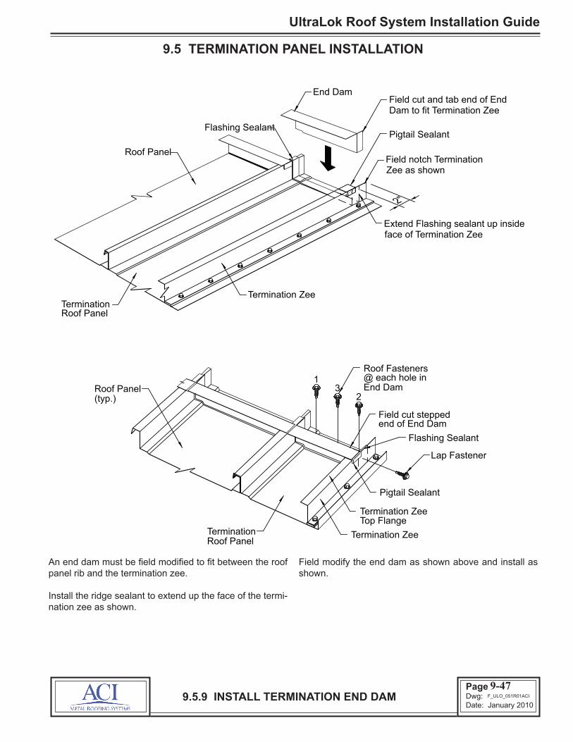
Page 69Dwg: Date: January 2010
UltraLok Roof System Installation Guide
9.5.9 INSTALL TERMINATION END DAM
9.5 TERMINATION PANEL INSTALLATION
An end dam must be field modified to fit between the roof panel rib and the termination zee.
Install the ridge sealant to extend up the face of the termi-nation zee as shown.
Field modify the end dam as shown above and install as shown.
9-47
End Dam
2"
Flashing Sealant
Termination Zee
Roof Panel
Termination
Field cut and tab end of End Dam to fit Termination Zee
Field notch Termination Zee as shown
Extend Flashing sealant up inside face of Termination Zee
Roof Panel
Pigtail Sealant
Roof Panel(typ.)
Roof Fasteners
Field cut stepped
@ each hole inEnd Dam
TerminationRoof Panel
Termination Zee
Termination ZeeTop Flange
Pigtail Sealant
Flashing Sealant
end of End Dam
Lap Fastener
13
2
F_ULO_051R01ACI

UltraLok Roof System Installation Guide
Page 70Dwg: Date: January 2010
9.6.1 ORIENTATION VIEW
9.6 RAKE TRIM INSTALLATION
The details in this section show the installation of the rake trim, peak box and end caps.
These details show the rake trim at a termination roof panel condition. The details at a starting roof panel condition are similar.
End Dams (typ.)
Roof Panels
Rake Trim
End Cap
Rake Trim
Slide Trim
Peak Box
9-48F_PCO_052R00BRS

Page 71Dwg: Date: January 2010
UltraLok Roof System Installation Guide
9.6.2 START RAKE TRIM AT EAVE
9.6 RAKE TRIM INSTALLATION
Install the rake trim from eave to ridge to provide for water-shed at the splices.
Install flashing sealant continuous along the top flange of the termination zee (or roof panel seam).
Start the down-slope end of the rake trim flush with the end of the roof panel.
Check that the rake trim is properly aligned with the face of the wall panel.
Fasten the rake trim to the termination zee with lap fasten-ers at 6” spacing, as shown. Be sure the fasteners do not penetrate the start clip tabs and are 2” from each side.
Be sure to check that the fasteners penetrate the center of the sealant and securely engage the termination zee (or roof panel seam).
9-49
Eave Trim
Eave Trim
Rake Trim
6"
Start or Termination Roof Panel
Termination Zee(or roof panel seam)
Flashing Sealant
Lap Fastener (LT4) @ 6" O.C.
Protective Paper
Flashing Sealant
Termination Zee
Starting End of Rake Trim(flush with end of roof panel and termination zee)
Start or Termination Roof Panel
Wall
Wall
F_ULO_053R00ACI

UltraLok Roof System Installation Guide
Page 72Dwg: Date: January 2010
9.6.3 RAKE TRIM ASSEMBLY AT SPLICE AND RIDGE
9.6 RAKE TRIM INSTALLATION
Assemble rake trim splices with tube sealant, LT4 (lap fasteners) and rivets as shown.
At the ridge, field cut the uphill end of the rake trim 2” back from the center line of the ridge.
At a high eave transition, field cut the end of the rake trim as required for a weathertight joint with the adjacent con-struction.
9-50
RAKE TRIM @ RIDGE
End Dam
RAKE TRIM SPLICE
Rake Trim
2"
Rake Trim
Finish end ofRake Trim
Upslope
1 1/2"
3/16" Dia.Pigtail
1/2"
Downslope Rake Trim
Tape Sealant
Downslope Rake Trim
Secure lap with 1/8"dia. Blind Rivets
so exposed edgePosition Rake Trim
is factory cut
Flashing Sealant
3/16" Dia. Bead Tube Sealant
Lap Fastener @ Termination Zee (or roof panel seam) and top of
Termination Zee(or roof panel seam)
Bend up or notch Rake Trim to clear End Dam
rake trim
F_ULO_054R01ACI

Page 73Dwg: Date: January 2010
UltraLok Roof System Installation Guide
9.6.4 INSTALL RAKE SLIDE TRIM
9.6 RAKE TRIM INSTALLATION
If the rake trim run is 30’ or less, the bottom edge of the rake trim can be attached directly to the wall with wall fasteners as shown.
If the rake trim run exceeds 30’, the bottom edge of the rake trim must be secured with the slide trim to allow for roof expansion/contraction.
Install the slide trim continuous along the bottom edge of the rake trim as shown.
In all cases, the bottom edge of the rake trim must be in-stalled straight and parallel to the roof line. Use a chalk line to guide the alignment of the rake trim’s bottom edge.
9-51
FIXED ATTACHMENT
IMPORTANT
SLIDING ATTACHMENT
Rake Trim
Wall Fastener@ 12" o.c. (max.)
Slide Trim
Wall Fastener@ 12" o.c. (max.)
Eave Trim
Wall
Corner Trim Starting end of Slide Trim(flush with face of corner trim)
Slide Trim
Rake Trim
For rake lengths (eave to ridge)exceeding 30', a sliding type attachment of the rake trim
to wall is required.
Rake Trim
(30' or Less) (Greater than 30')
F_ULO_055R00ACI

UltraLok Roof System Installation Guide
Page 74Dwg: Date: January 2010
9.6.5 INSTALL PEAK BOX
9.6 RAKE TRIM INSTALLATION
If the rake trim does not require the slide trim for expan-sion/contraction, the peak box can be installed with tube sealant and rivets in the same manner as a splice.
If the rake trim requires the slide trim for expansion/ con-traction, the peak box must be installed as shown in the above details.
Secure the top of the peak box by clinching its top edge around the top edge of the rake trim.
Secure the bottom edge of the peak box with the slide trim.
9-52
NOTE
Lap the sealants
End Dam
Rake Trim
Peak Box
Rake Trim
Clinch
Peak Box
Clinch
1/4" dia. Bead Tube Sealant
If slide trim is not required, attach Peak Box
to Rake Trim with 1/8" dia. blind rivets.
Slide Trim
Starting or Termination Roof Panel
Starting or Termination Roof Panel
F_PCO_056R00BRS

Page 75Dwg: Date: January 2010
UltraLok Roof System Installation Guide
9.6.6 INSTALL END CAPS
9.6 RAKE TRIM INSTALLATION
The rake trim end cap is only required for roof applications without eave gutter.
The end cap must be field cut and a tab bent to fit the ter-mination zee or starting roof panel as shown.
Install the end cap with tube sealant and rivets in the same manner as a splice.
9-53
NOTE
END CAP DETAIL
Eave Trim
Rake TrimEnd Cap
Termination
Eave Trim
Starting or
Rake Trim
Rake TrimEnd Cap
RakeTrim
1/2"
Roof Panel
Field Cut and bend tab to fit terminationzee or starting roof panel
Roof Panel
Starting orTermination
Notch to clear Roof Panel
Rake Trim End Cap is not required when eave has Eave
Gutter or Eave Box Trim
Set End Cap flush with end of Rake Trim
Secure with 1/8" dia. Blind Rivets
F_PCO_057R00BRS
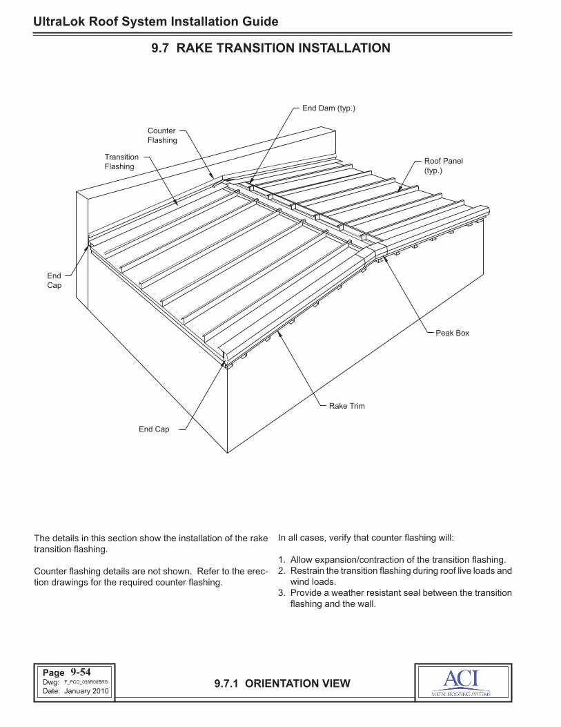
UltraLok Roof System Installation Guide
Page 76Dwg: Date: January 2010
9.7.1 ORIENTATION VIEW
9.7 RAKE TRANSITION INSTALLATION
The details in this section show the installation of the rake transition flashing.
Counter flashing details are not shown. Refer to the erec-tion drawings for the required counter flashing.
In all cases, verify that counter flashing will:
1. Allow expansion/contraction of the transition flashing.2. Restrain the transition flashing during roof live loads and
wind loads.3. Provide a weather resistant seal between the transition
flashing and the wall.
9-54
Peak Box
Rake Trim
TransitionFlashing
FlashingCounter
End Dam (typ.)
EndCap
End Cap
(typ.)Roof Panel
F_PCO_058R00BRS
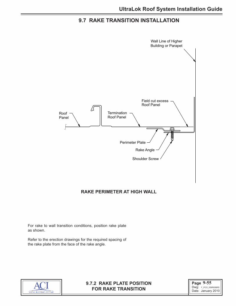
Page 77Dwg: Date: January 2010
UltraLok Roof System Installation Guide
9.7 RAKE TRANSITION INSTALLATION
For rake to wall transition conditions, position rake plate as shown.
Refer to the erection drawings for the required spacing of the rake plate from the face of the rake angle.
9.7.2 RAKE PLATE POSITION FOR RAKE TRANSITION
9-55
Perimeter Plate
Rake Angle
Field cut excess Roof Panel
Panel Roof Termination
Roof Panel
Wall Line of Higher Building or Parapet
Shoulder Screw
F_PCO_059R00BRS
RAKE PERIMETER AT HIGH WALL
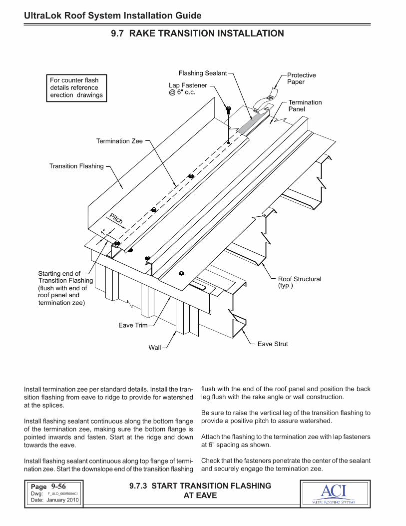
UltraLok Roof System Installation Guide
Page 78Dwg: Date: January 2010
9.7.3 START TRANSITION FLASHING AT EAVE
9.7 RAKE TRANSITION INSTALLATION
Install termination zee per standard details. Install the tran-sition flashing from eave to ridge to provide for watershed at the splices.
Install flashing sealant continuous along the bottom flange of the termination zee, making sure the bottom flange is pointed inwards and fasten. Start at the ridge and down towards the eave.
Install flashing sealant continuous along top flange of termi-nation zee. Start the downslope end of the transition flashing
flush with the end of the roof panel and position the back leg flush with the rake angle or wall construction.
Be sure to raise the vertical leg of the transition flashing to provide a positive pitch to assure watershed.
Attach the flashing to the termination zee with lap fasteners at 6” spacing as shown.
Check that the fasteners penetrate the center of the sealant and securely engage the termination zee.
9-56
Eave Trim
WallEave Strut
1"
Transition Flashing
Flashing Sealant
Termination Zee
Pitch
@ 6" o.c.Lap Fastener Paper
TerminationPanel
Protective
Starting end of Transition Flashing(flush with end of roof panel and termination zee)
Roof Structural (typ.)
For counter flash details reference erection drawings
F_ULO_060R00ACI

Page 79Dwg: Date: January 2010
UltraLok Roof System Installation Guide
9.7.4 TRANSITION FLASHING ASSEMBLY AT SPLICE AND RIDGE
9.7 RAKE TRANSITION INSTALLATION
Assemble transition flashing splices with flashing sealant and lap fasteners as shown. Wipe dry and clean the lap-ping surfaces of the flashing.
Bend or notch the flashing’s lip to clear the top flange of the end dam.
At the ridge, field cut the end of the flashing 2” away from the center line of the ridge.
At a high eave transition, field cut the end of the flash-ing as required for a weathertight joint with the adjacent construction.
9-57
TRANSITION FLASHING SPLICE
TRANSITION FLASH AT RIDGE
Transition Flashing Pitch
Pitch
Rake Angle
Flashing
Flashing Transition
flashing to clear Bend up or notch
End Dam
2"
End Dam
Transition Flashing Finish end of
Flashing Sealant
Protective Paper
Pitch
1/8" dia. rivets @ vertical surface
so exposed edge Position Flashing
is factory cut
2"
Transition Flashing
1/2"
Sealant
Angle Rake
@ horizontal Lap Fasteners
surface
Flashing Sealant
Pigtail Sealant
Roof S
lope
(Cut 2" away from ridge center line)
F_PCO_061R00BRS

UltraLok Roof System Installation Guide
Page 80Dwg: Date: January 2010
9.8.1 ORIENTATION VIEW
9.8 RIDGE COVER INSTALLATION
The details in this section show the installation of the ridge cover.
The ridge cover can start or finish at either a rake trim con-dition or a rake transition condition.
9-58
Rake Trim
Corner Box
Eave Gutter
Counter Flashing
Transition Flashing
Peak Box
Ridge End Cap
Ridge Flashing
Ridge End Plate
F_PCO_062R00BRS

Page 81Dwg: Date: January 2010
UltraLok Roof System Installation Guide
9.8.2 INSTALL END CAP AT RAKE TRIM
9.8 RIDGE COVER INSTALLATION
Position the end cap so its face is flush with the face of the rake trim.
Fasten the end cap to the rake trim with (2) rivets as shown.
Install flashing sealant on top and bottom of the end cap as shown. Align the edge of the sealant flush with face of the end cap and extend the sealant to align with the end dams uphill edge.
Install flashing sealant continuous along the top flange of the end dams. Lap the end of the sealant over the end cap sealant.
9-59
Roof Panel
Lap the sealants
Flashing Sealant
(@ each sideBlind Rivet
1/8" dia.
of End Cap)
Rake Trim
END CAP DETAIL
End Cap
End Dam
Flashing Sealant
Align Flashing Sealantwith up-hill edge of end dam
Uphill Edge of End Dam
F_PCO_063R01BRS

UltraLok Roof System Installation Guide
Page 82Dwg: Date: January 2010
9.8.3 INSTALL RIDGE COVER AT RAKE TRIM
9.8 RIDGE COVER INSTALLATION
Install the ridge cover to span across the opposing end dam runs as shown.
Position the end of the ridge cover flush with the face of the end cap.
Align the center of the ridge cover over the ridge centerline. Use a string line to assure a straight ridge cover installa-tion.
Fasten the ridge cover to the end dams with lap fasteners
spaced as shown. Check that the fasteners penetrate the center of the sealant and securely engage the end dams.
Important: To provide watershed, the ridge cover must have a positive pitch, even during roof panel contrac-tion.
To increase the ridge cover’s pitch, first fasten only one edge of the ridge cover, then push on the opposite edge of the ridge cover to deflect its center upward. Hold it in this position with clamps while fastening the other edge.
9-60
Roof Panel
Rake Trim
End of Ridge Cover(flush with face of
Lap Fasteners(typ.) Position Ridge Cover
so exposed end isfactory cut
Ridge Cover
Lap Fasteners at 6" o.c.
Protective
1/2"
end cap)
Clamp
Flashing Sealant
Note: Opposite slope roof panels omitted for clarity.
End Dam
Paper
F_ULO_064R00ACI

Page 83Dwg: Date: January 2010
UltraLok Roof System Installation Guide
9.8.4 INSTALL END PLATE AT RAKE TRANSITION
9.8 RIDGE COVER INSTALLATION
Position the end plate so its face is flush with the face of the transition flashing.
Fasten the end plate to the transition flashing with rivets as shown.
Install flashing sealant on top of the end plate as shown. Position the edge of the sealant flush against the face of
the transition flashing and extend the ends of the sealant to align with the end dam’s uphill edge.
Install flashing sealant continuous along the top flange of the end dams. Lap the end of the sealant over the end cap.
9-61
Roof Panel
Flashing Sealant
Flashing SealantFlashingTransition
Rake
3/16" bead of TubeSealant under edgeof End Plate
Lap the sealants
Angle
engage Rake Angle)(Rivets must not
1/8" dia. Rivet
End Plate(RTT_)
End Dam
Note: Opposite slope roof panels omitted for clarity.
Align Flashing Sealantwith up-hill edge of end dam
F_PCO_065R01BRS

UltraLok Roof System Installation Guide
Page 84Dwg: Date: January 2010
9.8.5 INSTALL RIDGE COVER AT RAKE TRANSITION
9.8 RIDGE COVER INSTALLATION
Install the ridge cover to span across the opposing end dam runs as shown.
Position the end of the ridge cover flush against the face of the transition flashing.
Align the center of the ridge cover over the ridge centerline. Use a string line to assure a straight ridge cover installa-tion.
Fasten the ridge cover to the end dams with lap fasteners
spaced as shown. Check that the fasteners penetrate the center of the sealant and securely engage the termination zee.
Important: To provide watershed, the ridge cover must have a positive pitch, even during roof panel contrac-tion.
To increase the ridge cover’s pitch, first fasten only one edge of the ridge cover, then push on the opposite edge of the ridge cover to deflect its center upward. Hold it in this position with clamps while fastening the other edge.
9-62
Roof Panel
Lap Fasteners(typ.)
End Plate
Ridge Cover
ProtectivePaper
End Dam
Clamp
RakeAngle
1/4" dia. BeadTube Sealant
TransitionFlashing
Note: Opposite slope roofpanels omitted for clarity.
Butt end of Ridge cover flush against End Plate
Flashing Sealant
Lap Fasteners at 6" o.c.
F_ULO_066R00ACI

Page 85Dwg: Date: January 2010
UltraLok Roof System Installation Guide
9.8.6 RIDGE COVER ASSEMBLY AT SPLICE
9.8 RIDGE COVER INSTALLATION
Assemble the ridge cover splices with flashing sealant and lap fasteners as shown.
Important: The splice fasteners must be installed care-fully to avoid downward deflection and buckling of the ridge cover ends.
9-63
Ridge Cover
Flashing Sealant
(2) 1/4" dia. beads Tube Sealant
Flashing Sealant
Lap Fasteners
End Dam
Position lap so exposed edge is factory cut
Ridge Cover
End Dam
panels omitted for clarity. Note: Opposite slope roof
F_PCO_067R00BRS

UltraLok Roof System Installation Guide
Page 86Dwg: Date: January 2010
9.9.1 ORIENTATION VIEW
9.9 HIGH EAVE TRANSITION INSTALLATION
The details in this section show the installation of high eave transition flashing.
The transition flashing can start or finish at either a rake trim condition or a rake transition condition.
In all cases, verify that counter flashing will:
1. Restrain the transition flashing during roof live loads and wind loads.
2. Provide a weather resistant seal between the transition flashing and the wall.
9-64
Transition Flashing
Counter Flashing
Rake Trim
Transition Flashing
Roof Panel (typ.)
Counter Flashing
F_PCO_068R00BRS

Page 87Dwg: Date: January 2010
UltraLok Roof System Installation Guide
9.9.2 INSTALL END CAP OR END PLATEAT RAKE TRIM OR RAKE TRANSITION
9.9 HIGH EAVE TRANSITION INSTALLATION
Install end slip cap to wall using the rake trim to locateposition.
Field cut the end cap or end plate to fit as shown.
Position the end transition plate so its face is flush with the face of the rake trim or transition flashing.
Fasten the end cap or end plate with rivets as shown.
Install flashing sealant on top of the end cap or end plate as shown. Align the edge of the sealant flush with face of the end cap or transition flashing and extend the sealant to align with the end dams.
Install flashing sealant continuous along the top flange of the end dams. Lap the end of the sealant over the end cap sealant.
9-65
Field Trim
END CAP
END SLIP CAP
Attach toHigh Wall
PanelRoof
Rake Trim
Wall or
RoofPanel
End Dam
Parapet
Flashing Sealant
Transition End Plate
Flashing Sealant
Blind Rivet1/8" dia.
3/16" bead of TubeSealant under edgeof End Plate
FlashingSealant
1/8" dia. Blind Rivet
Lap the sealants
End Dam
FlashingTransition
END CAP @ RAKE TRIM
END PLATE @ RAKE TRANSITION
Transition End Cap
Lap the sealants
Flashing Sealant
End Slip Cap2" Min. Slip Joint
Field Trim
Align FlashingSealant withup-hill edge ofend dam
F_PCO_069R01BRS
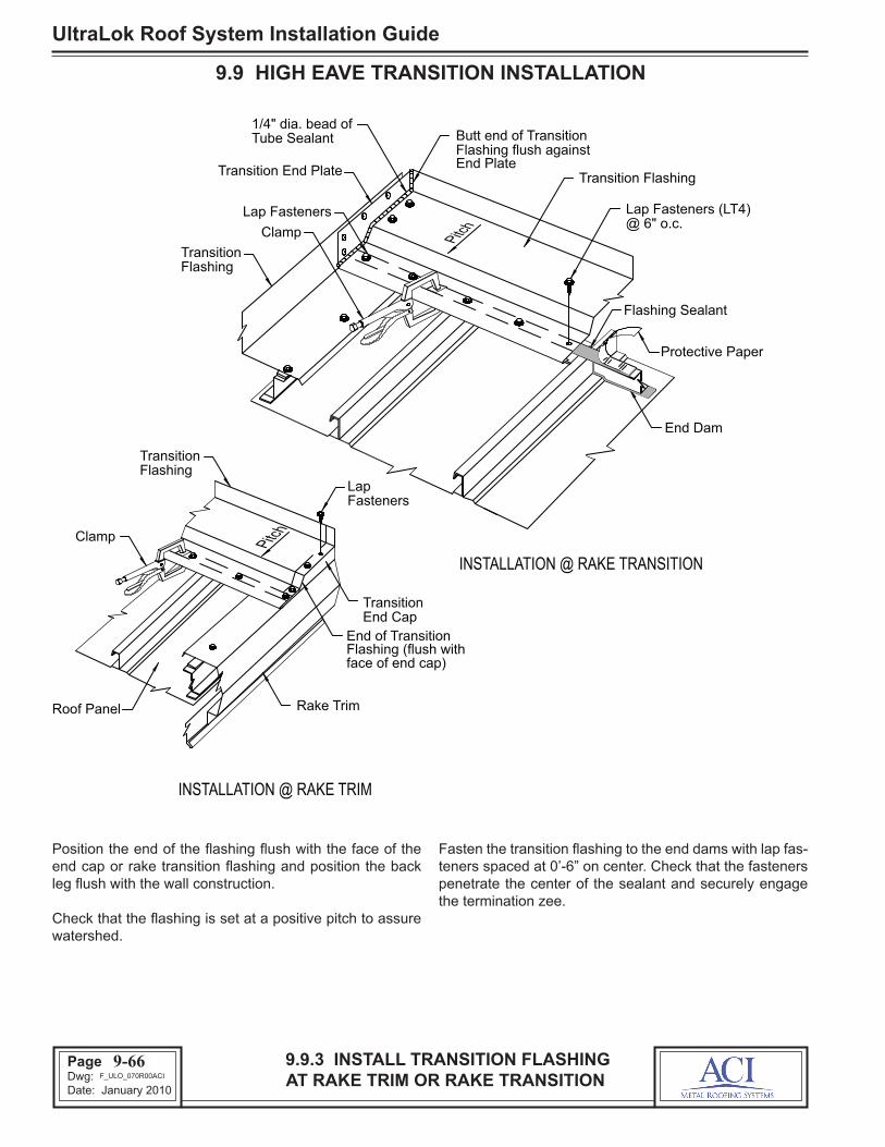
UltraLok Roof System Installation Guide
Page 88Dwg: Date: January 2010
9.9.3 INSTALL TRANSITION FLASHINGAT RAKE TRIM OR RAKE TRANSITION
9.9 HIGH EAVE TRANSITION INSTALLATION
Position the end of the flashing flush with the face of the end cap or rake transition flashing and position the back leg flush with the wall construction.
Check that the flashing is set at a positive pitch to assure watershed.
Fasten the transition flashing to the end dams with lap fas-teners spaced at 0’-6” on center. Check that the fasteners penetrate the center of the sealant and securely engage the termination zee.
9-66
LapFasteners
TransitionFlashing
Clamp
Rake TrimRoof Panel
Lap Fasteners (LT4)@ 6" o.c.
Flashing Sealant
Protective Paper
Butt end of Transition
Transition End Plate
TransitionFlashing
Flashing flush against
End of TransitionFlashing (flush withface of end cap)
TransitionEnd Cap
1/4" dia. bead ofTube Sealant
Lap Fasteners
End PlateTransition Flashing
Clamp
End Dam
INSTALLATION @ RAKE TRIM
INSTALLATION @ RAKE TRANSITION
Pitch
Pitch
F_ULO_070R00ACI

Page 89Dwg: Date: January 2010
UltraLok Roof System Installation Guide
9.9.4 TRANSITION FLASHING ASSEMBLY AT SPLICES
9.9 HIGH EAVE TRANSITION INSTALLATION
Assemble the transition flashing splices with flashing sealant and lap fasteners as shown.
Important: The splice fasteners must be installed care-fully to avoid downward deflection and buckling of the flashing ends.
9-67
Roof Panel
Roof Panel
Transition
Lap Fasteners
Flashing
Transition Flashing
1/8" dia. Blind Rivet
1/2"
Pitch
End Dam
Pigtail Sealant
Flashing Sealant
Flashing Sealant
Flashing Transition
Protective Paper
2"
2" Lap
End Dam
F_PCO_071R00BRS
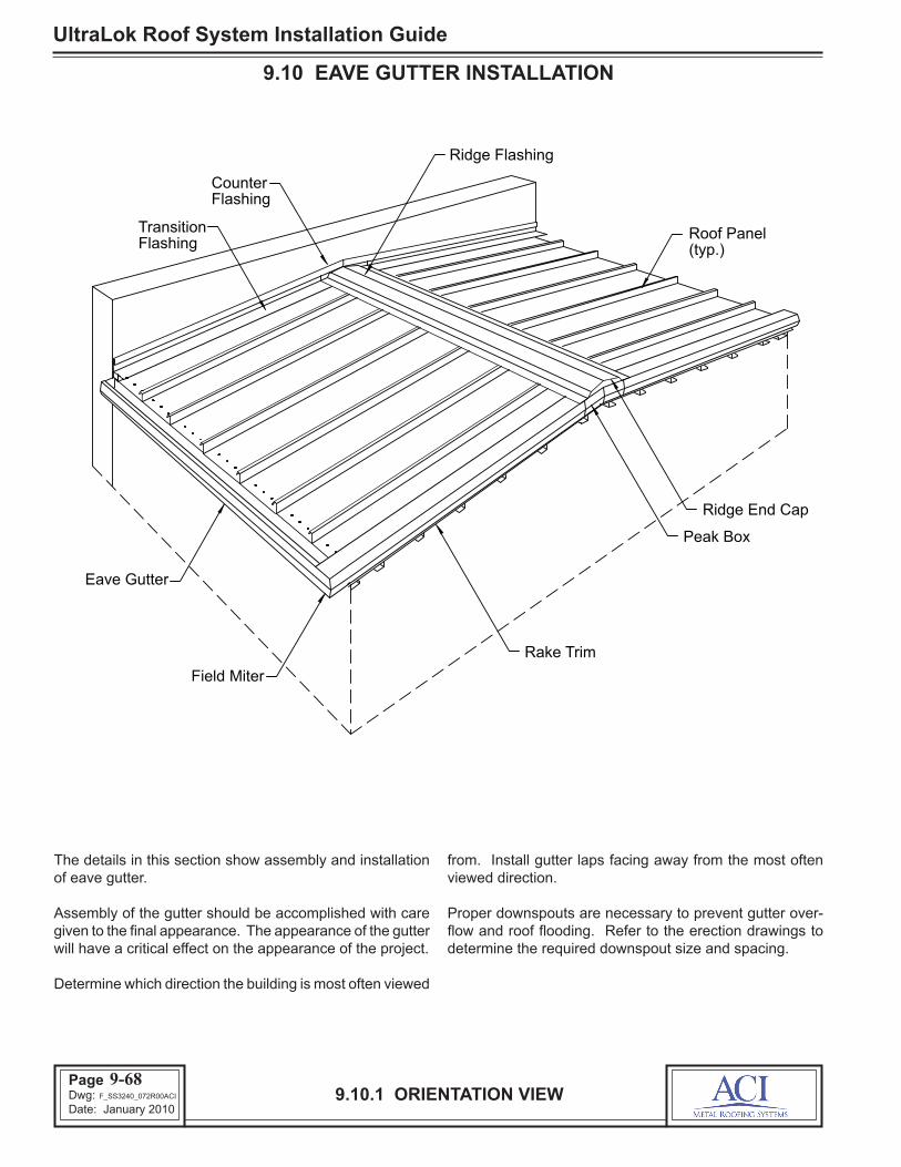
UltraLok Roof System Installation Guide
Page 90Dwg: Date: January 2010
9.10.1 ORIENTATION VIEW
9.10 EAVE GUTTER INSTALLATION
The details in this section show assembly and installation of eave gutter.
Assembly of the gutter should be accomplished with care given to the final appearance. The appearance of the gutter will have a critical effect on the appearance of the project.
Determine which direction the building is most often viewed
from. Install gutter laps facing away from the most often viewed direction.
Proper downspouts are necessary to prevent gutter over-flow and roof flooding. Refer to the erection drawings to determine the required downspout size and spacing.
9-68
Peak Box
Rake Trim
TransitionFlashing
FlashingCounter
(typ.)Roof Panel
Ridge End Cap
Ridge Flashing
Field Miter
Eave Gutter
F_SS3240_072R00ACI

Page 91Dwg: Date: January 2010
UltraLok Roof System Installation Guide
9.10.2 ASSEMBLE EAVE GUTTER
9.10 EAVE GUTTER INSTALLATION
An erection tip is to layout the gutter assemblies in managable lengths (30’-40’) before raising to the roof.
Start and finish the gutter ends flush with the exterior face of the rake walls.
If gutter and rake are both required on building, extend both as required to field miter. See page 9-71.
Assemble the gutter end caps and splices with tube sealant and rivets as shown in the above details on the ground, then temporarily clamp sections to the edge of the roof panel.
9-69
EAVE GUTTER END CAP
EAVE GUTTER SPLICE
End Cap Gutter
At finish end field cut Gutter to required length
Tube Sealant Dia. Beads (2) 3/16"
1/8" dia. Blind Rivets
Gutter End Cap
Gutter
Secure with
1/2"
Gutter
1/2"
dia. beads (2) 3/16"
Tube Sealant
Gutter
1/2"
Gutter
1/8" dia. Rivets @ front, bottom & back of Gutter
2"
so exposed edge Position Gutter
is factory cut
2"
notch Field cut
(Flush with end of Gutter)
F_PCO_073R00BRS

UltraLok Roof System Installation Guide
Page 92Dwg: Date: January 2010
9.10.3 INSTALL EAVE GUTTER
9.10 EAVE GUTTER INSTALLATION
Lift the gutter assembly into position under the edge of the roof panels and temporarily clamp the back flange of the gutter to the roof panel.
Position the back face of the gutter assembly flush against the eave trim and position its ends flush with the exterior face of the rake wall. (Extend when field miter is required, see page 9-71.)
Fasten the gutter’s back flange to the underside of the roof panel with lap fasteners.
Check that the lap fasteners are securely engaged into the gutter’s back flange.
Apply strips of flashing sealant 3" long to the inside of the gutter supports at uphill screw location.
Align the outer edge of the gutter straight and level. Use a string line to assure that the gutter is straight.
Install the gutter supports and fasten to the roof panel with (2) lap fasteners and (1) roof fastener (outside of the build-ing envelope). Refer to erection drawings for the required gutter support spacing.
Fasten the gutter’s outer flange to the end of the gutter support with a lap fastener (LT4) as shown.
9-70
NOTE
Wall
Gutter Assembly
End of GutterAssembly
Roof Panel (typ.)
(3) per panelLap Fasteners
SupportGutter
Lap Fasteners(2) per support
LT4-Lap Fastener
Refer to shop drawings for Gutter Support spacing
Clamp
Low Side Wall
Rake WallRoof fastener (1E)(one) per support
(outside of buildingenvelope)
Roof Fastener (1E)
Lap Fastener
(One per ULGS)
(LT4)
(FL-ULGS)Gutter Strap
(outside of buildingenvelope)
F_ULO_074R00ACI

Page 93Dwg: Date: January 2010
UltraLok Roof System Installation Guide
9.10.4 FIELD MITER GUTTER & RAKE TRIM
9.10 EAVE GUTTER INSTALLATION
Field Miter corners of gutter and rake as required.
Install bird stop on gutter end between the outside face of the gutter and the end of the panel hem or termination zee.
Attach the gutter and rake trim together using pop rivets and sealant as required.
9-71
RakeTrim
Rivets (typ.)1/8" dia.
Gutter
PanelRoof
Gutter
PanelRoof
TrimRake
Closure / Bird Stop
Blind Rivet1/8" dia.
(below rake and on top of gutter end)
F_ULO_075R00ACI

UltraLok Roof System Installation Guide
Page 94Dwg: Date: January 2010
9.11.1 HIP AND VALLEY DETAILS
9.11 HIP AND VALLEY INSTALLATION
The above details show typical hip and valley details. Refer to the erection drawings for specific hip and valley details.
Hip conditions are similar to ridge conditions, except special end dams and hip support cees are required to accommo-date the beveled roof panel ends.
9-72
Valley Plate
To form corner, field cut & tab End Dams
with Tape Sealant and RivetsValley Pan & secure to End DamField cut and bend up end of
and Valley Flashing. Secure with tube
Hip Cover
Ridge Cover
Diverter
sealant and rivets
Sealant and Lap
Roof
TZ210 (fieldcut to fit
Panels)
Valley FlashingPanel bevel
Endlap Sealant
Zee with Tube SealantSeal ends of Termination
Field cut Roof
Hip Cover
Fasteners
2" lap with Flashing
Back-upAngle
Lap Fastner@ 6" o.c.
Roof Fasteners@ 3" o.c.
Flashing Sealant
6" lap with Endlap Sealant and Roof Fasteners
VALLEY SECTION (High System)
ValleyFlashing
Diverter
Valley Plate
Roof Panel
Valley Support
VALLEY SECTION (Low System)
ValleyFlashing
Diverter
Roof Panel
Valley Support
Valley Plate
FL-TZ210 (Field Cut to fitRoof Panels)
Lap Fastner
Flashing SealantTop & Bottom
Top & Bottom
F_ULO_076R00ACI