ultrashield® plus - essex wire
TRANSCRIPT
2
UltraShield® Plus
essexwire.com
Inverter duty magnet wire is a type of magnet wire that has a higher resistance to voltage
spikes, and Essex UltraShield® Plus has been the market leader for nearly two decades.
The objective of this paper is to explain how inverter duty wire allows electric motors
to function properly in the modern power environment and compare different options
versus Essex UltraShield® Plus to determine if it is still the best product on the market.
In doing so, an understanding of essential concepts behind electric motors and
the related applications of inverter drives is needed. To help illustrate key points an
examination into the components involved in the insulation systems that are used within
electric motors and how these systems can deteriorate over time when subjected to
stress will be given. Additionally, attention will be paid to the detrimental effects of
partial discharge and how these problems can be mitigated, with a requisite degree of
technical depth.
Finally, there is a presentation of results to a series of tests that were conducted to help
illustrate the strengths and weakness of various wires available on the market.
Ultimately, it is the responsibility of all operators to develop the designs and best
practices that keep their motors running smoothly for years to come. This white paper is
designed to help all operators to find success.
Background
Though there are several different types of motors, which are all designed to achieve a
similar goal, electric motors have one basic function: turning electricity into motion.
For modern operators, various factors determine how each will use electric motors and
one of the key determinations is whether an application requires constant speed or
varying speeds.
When operators require varying speeds, they must consider the actual load. This requires
understanding two critical terms: “Torque” and “Power.”
ULTRASHIELD® PLUS AND THE INVERTER DUTY WIRE MARKET
3
UltraShield® Plus
essexwire.com
Torque, which is also known as “moment” or “moment of force,” is a rotational force. If a
linear force can be considered either a push or a pull, a torque can be thought of as a twist
applied to an object. For its part, power can be defined as the rate of work being done. In
this usage, power should be thought of as the product of torque and rotational speed.
Breaking things down further, it is important to recognize that not all loads are the same.
But these loads can be generally separated into three different categories:
1. Variable Torque
When less effort is needed as the speed drops
(Examples: centrifugal pumps or fans)
2. Constant Torque
When the same effort is needed regardless of the speed
(Examples: traction applications, conveyors, mixers, extruders, screw compressors)
3. Constant Power
When the torque is high but the speed is low and vice versa
(Examples: applications where material is being rolled and the diameter changes
during rolling)
Basics of An Inverter
An inverter drive is a mechanism that can control speed and torque of an electric motor.
The inverter achieves this by adjusting voltage frequency, and it is critical in a large
number of industrial applications. Inverters (including “variable frequency drives” or
VFDs) are used in everything from electric vehicle motors and wind generators to inverter
duty drive motors and high-voltage rotating machines.
The process of making the vital adjustments required across so many modern
applications is technical in nature, but the adjustment of the magnetizing current -- and
therefore the torque of the motor with regard to the mechanical load -- can be achieved
by controlling the amplitude and frequency of the supplied voltage.
One control strategy used by inverters is V/Hz control. This strategy assumes that when
the voltage-to-frequency ratio (V1 / f1) remains constant that the torque also remains
constant, whereas the torque is only constant up to the motor base voltage (rated) and
frequency (fb).
When the voltage drops faster than the frequency, the torque also drops. This makes it
suitable for “Variable Torque” applications, with the torque hitting its maximum upper
limit at the motor base voltage (rated) and frequency (fb).
Meanwhile, when the voltage remains constant while the frequency increases, the
magnetic field of the motor weakens. This makes it suitable for “Constant Power”
applications, with the torque hitting its maximum upper limit at the motor base voltage
(rated) and frequency (fb) before dropping as the speed increases. (Special motor
constructions may be required for this application.)
The key attribute of an inverter is its ability to convert line input to inverter output
voltage. This consists of a solid-state power electronics conversion system that is made of
three distinct subsystems: a rectifier, a DC bus, and an inverter.
Under no-load or light-load conditions, the DC link voltage stabilizes itself at
approximately 1.41*Vin (RMS) level. At full load, the DC link voltage stabilizes at
approximately 1.35*Vin (RMS) level. In some applications in which the DC power source is
available, such as solar applications, inverters are configured as DC-AC drives.
4
UltraShield® Plus
essexwire.com
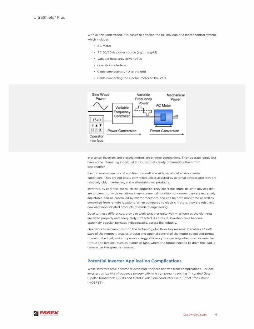
With all this understood, it is easier to envision the full makeup of a motor control system,
which includes:
• AC motor
• AC 50/60Hz power source (e.g., the grid)
• Variable frequency drive (VFD)
• Operator’s interface
• Cable connecting VFD to the grid
• Cable connecting the electric motor to the VFD
In a sense, inverters and electric motors are strange companions. They operate jointly but
have some interesting individual attributes that clearly differentiate them from
one another.
Electric motors are robust and function well in a wide variety of environmental
conditions. They are not easily controlled unless assisted by external devices and they are
relatively old, time-tested, and well-established products.
Inverters, by contrast, are much the opposite. They are static, more-delicate devices that
are intolerant of wide variations in environmental conditions, however they are extremely
adjustable, can be controlled by microprocessors, and can be both monitored as well as
controlled from remote locations. When compared to electric motors, they are relatively
new and sophisticated products of modern engineering.
Despite these differences, they can work together quite well — as long as the elements
are sized properly and adequately protected. As a result, inverters have become
extremely popular, perhaps indispensable, across the industry.
Operators have been drawn to the technology for three key reasons: It enables a “soft”
start of the motor; it enables precise and optimal control of the motor speed and torque
to match the load, and it improves energy efficiency -- especially when used in variable-
torque applications, such as pumps or fans, where the torque needed to drive the load is
reduced as the speed is reduced.
Potential Inverter Application Complications
While inverters have become widespread, they are not free from complications. For one,
inverters utilize high-frequency power-switching components such as “Insulated Gate
Bipolar Transistors” (IGBT) and Metal-Oxide Semiconductor Field-Effect Transistors”
(MOSFET).

5
UltraShield® Plus
essexwire.com
Both IGBT and MOSFET elements act as “Fast Switches” in the power electronic circuit
and create issues, including current and voltage harmonics, voltage spikes, dV/dt related
issues, and common-mode voltage-related issues.
All of these issues can cause electrical and thermal insulation stress, winding overheating,
and common-mode bearing currents (electric fluting), which could lead to motor failure.
Furthermore, the output of the inverter is far from a pure sine wave. It uses the fast-
switching devices connected to the DC bus and turns them on or off to recreate the
equivalent of a sine wave on all three phases of the motor. One such technique uses
pulses that always have the same height (because they are generated from the DC bus),
but the voltage and frequency can be varied by changing the duration and polarity of the
pulses. This is referred to as “Pulse Width Modulation” (PWM).
The “Carrier Frequency” is the internal clock that the inverter uses to turn the switching
devices on or off. But deflection or distortion of the signal occurs every time a switching
device is turned on or off, and this contributes to the voltage and current harmonic
content. This appears as peaks superimposed over the voltage or current waveform.
Because the motor’s high frequency impedance is greater than the cable impedance,
the signal arriving at the motor through the cable is partially reflected, leading to the
superimposition of the reflected pulses with the arriving pulses. These overvoltage
superimposed pulses are called “overshoots,” and the amplitude of overshoots can
extend to twice the value of the DC bus voltage.
Basics of Insulating Systems and Deterioration
To prevent damage occurring between any two wires within an electric motor, insulation
systems are used. While the insulation solution can be incredibly effective against
ongoing stress, it is not without some inherent limitations.
Understanding that alone is enough for most industry professionals, as the technical
details can be overwhelming, but interested engineers should recognize that the rate of
deterioration of the insulating system is impacted by two main factors: the amplitude of
the overshoots (spikes) and the voltage rise rate (dV/dt).
* dV/dt is defined in the same way by all standards and examples are presented on the attached the graphs.).

6
UltraShield® Plus
essexwire.com
The rise time (tr) of the spikes can range from a few tens of nanoseconds to a few
microseconds and will have a direct influence on the insulation life. As the pulse
grows faster (meaning, with a smaller tr), the dV/dt ratio becomes greater and more
detrimental to the insulation. Typical dV/dt values are in the range of thousands of volts
per microsecond (such as 5kV/μs). These values are so large mostly due to the very low
tr values.
Overshoots primarily affect the insulation of the first turns. The detrimental effect
depends upon several factors, including the rise time of the voltage pulse; cable length
and type; number of motors connected; time between successive pulses; switching
frequency; and mode of the motor operation.
Basics of Partial Discharge
One of the most prevalent — and least understood — forms of system damage comes in
the form of “Partial Discharge” (PD). This known and documented phenomenon often
occurs in the air around the wire and, as the name implies, creates a partial, rather than
full, electrical breakdown.
Though partial discharges are temporary in nature and do not immediately prevent
equipment from continued operation, they do lead to longer-term damage.
The reason partial discharge does not receive more attention from operators is because
the chemistry that causes the breakdown within organic insulation systems is still an
active area of research.
What is known, however, is that ozone (O3) represents one chemical breakdown pathway.
Ozone can be highly aggressive and attack the organic components of the insulation
system, thereby causing deterioration.
What else is certain is that PD occurs around the wire rather than within the wire. This
typically means PD is occurring in the air surrounding the wire in accordance with
Paschen’s Law, although it can also take place in an environment such as transformer oil
or electric car transmission oil.
In instances when multiple partial discharges occur, electrical breakdown can follow much
more rapidly — within hours or even minutes.
PD develops when the insulation system receives a voltage beyond its “Partial Discharge
Inception Voltage” (PDIV), which is influenced by factors including windings design,
frequency, insulation type, temperature, air pressure, moisture, and altitude.
In assessing this risk, various standards refer to a “threshold of capacitance” that lies
within a range of 10-100 pC. For reference, 60Hz PD inception voltage is typically 200-
300V/mil in magnet wire, which translates to ~800V @ 10pC.
One other phenomenon to be aware of is the “Corona Effect.” This subset of partial
discharge includes UV emission, ozone emission, and ionization — three issues with the
potential to degrade insulators over time and further damage the system.
It is largely due to standard-grade wire’s inability to handle stresses caused by inverter
drives that has put increased pressure on manufacturers to develop suitable products.
More operators in the industry are now recognizing the severity of this risk and growing
increasingly frustrated by the lack of solutions on the market.
It is imperative for operators to know how to limit the potential damage from partial
discharge. The primary way that they can get this issue under control is by understanding
the insulation system’s Partial Discharge Inception Voltage and how it changes during
operation.
7
UltraShield® Plus
essexwire.com
Another critical step is to design the motor and inverter with an awareness of how
destructive PD can be. This naturally requires creating a forward-looking design. But it
also means paying close attention to existing failures that may have been initiated by
partial discharge.
Because it is quite possible that the failure inception point occurred long before full
electrical breakdown, operators should be suspicious of any failure that came during
normal operation or with low-voltage stress. Historical logging can be an asset when
assessing past events that may have led to brief voltage spikes above the partial
discharge inception voltage.
Basics of Insulation Stress Points
Unfortunately, a VFD adds additional electrical stresses in the motor and there are a
wide variety of stress points that lead to partial discharge. Though it is important to
note that not all of the following situations will cause partial discharge they are frequent
contributors to the problem:
Wire-to-wire
• Can occur due to turns of the same phase having potential difference due to high
rapid voltage rise time and may be amplified by a reflected wave.
• Can occur due to variation in dielectric medium between turns (air gap in the
varnish system)
Turn-to-ground
• Can occur due to peak voltages in winding
• Can occur due to wire(s) of a phase having insufficient air gap to a grounded surface
• Can occur due to insufficient insulation present to a grounded surface
• Can occur due to discontinuity in the varnish of secondary insulation
Phase-to-phase
• Can occur due to peak voltages in winding wire due to high rapid voltage rise time
or reflected wave
• Can occur due to insufficient air gap between phases
• Can occur due to insufficient insulation between phases
UltraShield® Plus is The Essex Solution
One of the most critical elements to the life expectancy of inverter duty wire is the design
of the filled layer. Typical inverter duty insulation systems use symmetrically shaped
particles, which are either nano-sized or non-nano-sized, in the filled layer.
Essex uses a mix of nano and non-nano particles as well as non-symmetrical shapes in
the filled layer. This diversity of particles creates a longer path for electrical charges to
travel. The objective of this design is to distribute and dissipate charges so that they are
less damaging to the insulation system. And it works. The result is a longer operating life
for inverter duty wire used in a partial discharge environment.
The term “Nanotechnology” is used for tiny inorganic particles that range from tens to
hundreds of nanometers. The benefits are significant in power applications. As just a few
examples, they can help improve the dispersion of the particles and improve thermal and
mechanical performances by enabling thinner enamel layers and improved heat transfer
and flexibility.
8
UltraShield® Plus
essexwire.com
Several factors of the enamel system also dictate the theoretical PDIV level, including
operating temperature and other environmental conditions. The size and distribution of
filler particles and the thickness of the filled layer will impact the mitigation of PD in the
enamel as well.
As a result, UltraShield® Plus offers a superior performance over other wires on the market
in a PD environment. Specifically, it provides the following benefits:
• Extended operating life; lowering costs over time
• Excellent properties retention key for post-winding performance
• Increased performance at elevated temperature
This is why UltraShield® Plus has been utilizing nanotechnology since 1997 — even
advancing to use particles in the single-digit micrometer range.
Although each of the coats plays a specific and critical role in the performance of the
wire, the overall performance and PD-resistance of UltraShield® Plus inverter duty wires
are achieved by the special formulation of the coat that contains the filler.
To break it all down simply, the UltraShield® Plus system includes an optimized balance
of nano and micro particles and maximizes long-term performance. It also offers an ideal
balance between mechanical and electrical performance.
As part of the design, Essex achieved the solution’s desired enhanced electrical
performance by choosing and employing:
• Suitable mixture of inorganic particles
• Size optimization and size distribution
• Dispersion in the enamel
• “Wetting” of the inorganic particles
There is a sensitive trade-off between the electrical and mechanical performances of the
wire and their correlation to the size of the particles. Manufacturers of inverter duty wires
that use nano particles claim that this design increases particle aspect ratio and increases
the length of the creepage path – the crepage path is the shortest path between two
conductive components, measured along the surface of the insulation, the creepage
surface. The creepage distance is the length of that path.
Silica (SiO2) particles are often widely used; these silica particles are roughly spherical
and not elongated, which means that the aspect ratio does not increase and the creepage
path actually becomes shorter. In the end, this means that the benefit is limited to
mechanical performance and, namely, abrasion resistance.
By contrast, there are clear benefits to using micro-sized inorganic particles. They have
been shown to improve long-term electrical performance, voltage endurance, inverter
duty withstand stress, and pulse endurance.
The key takeaway is that the combination of micro- and nano-sized inorganic particles
in the Essex solution creates a synergistic effect between particles that extends life
expectancy and raises overall performance levels in a PD environment.
Inverter Duty Wire Testing Overview
When a new magnet wire is developed, it goes through a rigorous battery of tests to
document its performance capabilities and ability to comply to various standards. This
process is repeated many times — for every iteration developed — to find the best
solution.
Like others in the market, UltraShield® Plus has undergone many tests since its
introduction to prove its performance. Overall, the product has achieved results that are
20 times better than the competition, in some cases.
9
UltraShield® Plus
essexwire.com
The following represents a partial list of common tests for wire in the industry, focusing
on those most relevant to inverter applications.
Electric
• AC Breakdown Ramp Voltage
• DC Breakdown Ramp Voltage
• Partial Discharge Inception Voltage
• Partial Discharge Extinction Voltage
• Voltage Endurance Test Withstand
• High Frequency Endurance Test Withstand
• Dissipation Factor
• Insulation Resistance
• Polarization Index
• Permittivity / Dielectric Constant
• Conductor Resistance
Chemical
• Solubility
• Resistance to Refrigerants and other Chemicals
Thermal
• Thermal Stability.
• Thermal Class.
• Thermoplastic Flow (Cut-Through).
• Heat Shock.
Physical / Mechanical
• Dimensional
• Adhesion
• Flexibility (Mandrel Flexibility)
• Abrasion Resistance
• Unilateral Scrape
• Repeated Scrape
• Elongation
• Springback
• Windability
• Coefficient of Friction
• Solderability
UltraShield® Plus vs. GP/MR-200® (GP)
The dielectric constant of UltraShield® Plus insulation system (among other factors)
drives the partial discharge performance and other beneficial electrical properties. Film
thickness also drives the partial discharge inception voltage — a factor that must be
considered when evaluating different systems.
10
UltraShield® Plus
essexwire.com
Due to similar enamel systems, UltraShield® Plus and GP/MR-200 have similar PDIV levels.
The key element for longevity in a partial discharge environment is mitigating partial
discharge after inception — an overwhelming advantage of UltraShield® Plus compared to
a standard enamel system.
Increasing the ability to withstand partial discharge is another key to long-term motor
reliability in an inverter environment, and the UltraShield® Plus insulation system is
specifically designed to resist partial discharge while offering Increased abrasion
resistance, increased voltage endurance, and excellent property retention after winding
Once partial discharge forms it will exist until the applied voltage drops below the
extinguish voltage. Whenever partial discharge is occurring, the mitigation technique of
the insulation system is key to longevity.
Overall, UltraShield® Plus has a longer life in a partial discharge environment due to three
key factors:
• Resistance to insulation degradation
• Filled layer with inorganic particles that distribute and dissipate the partial
discharge energy
• Better performance at increased operating temperatures and post-elongation
UltraShield® Plus vs. Inverter Duty Wire Market Competition
UltraShield® Plus was then subjected to the same tests as Competition A (Comp A).
For disclosure, it must be noted that all tested wires are available on the market and
that the tested wires were of the same size and build in all of the presented results. In
general, three different sizes were subjected to the benchmarking studies: 1.000mm,
1.024/18AWG, and 1.450mm/15AWG. Lastly, each type of test was performed in identical
conditions using the same test equipment.
For a more detailed breakdown of the testing parameters used, see Appendix.
General Performance Tests
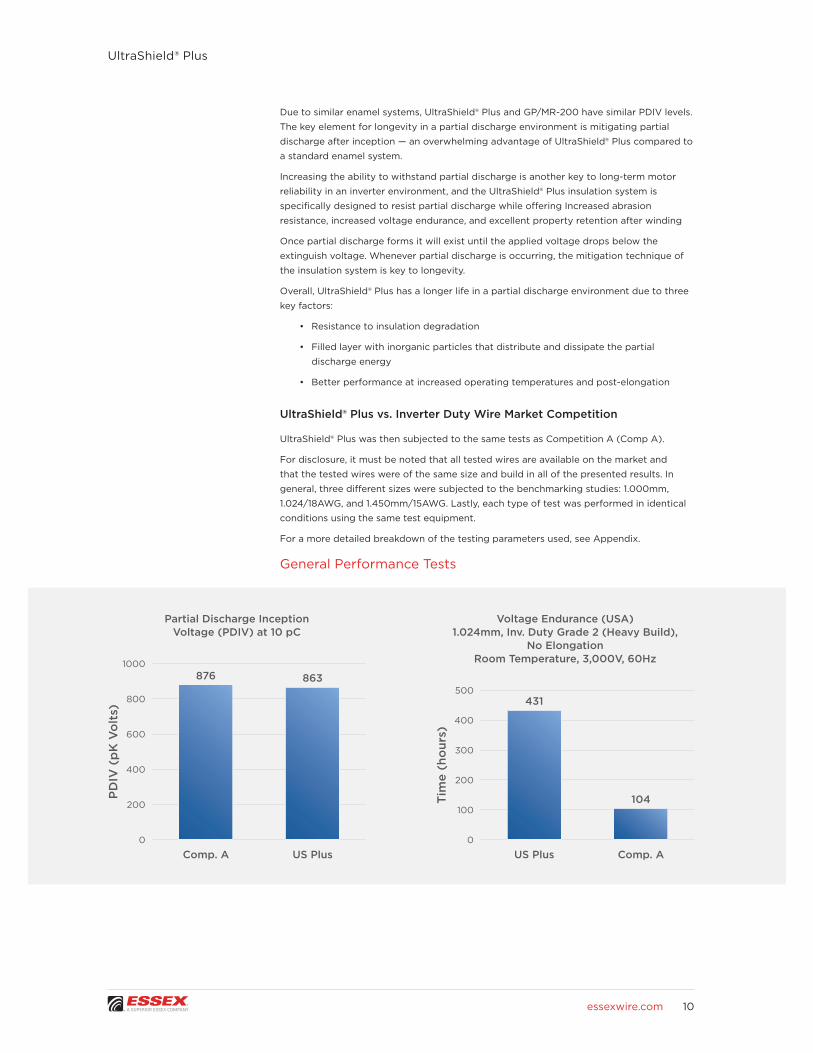
Partial Discharge Inception Voltage (PDIV) at 10 pC
Voltage Endurance (USA)1.024mm, Inv. Duty Grade 2 (Heavy Build),
No ElongationRoom Temperature, 3,000V, 60Hz1000
500800
400600
300
400200
200 100
0 0
PD
IV (
pK
Vo
lts)
Tim
e (h
our
s)
Comp. A Comp. AUS Plus US Plus
876
431
863
104

11
UltraShield® Plus
essexwire.com
When it comes to PDIV testing, there is no clear advantage for any of the tested wires,
including the performance of Comp. A and UltraShield® Plus wires. UltraShield® Plus does,
however, have a strong advantage over other competitor wires in the Voltage Endurance
Withstand test.
Inverter Duty Test (USA)15 AWG, Inverter Duty Grade 2 (Heavy Build)
575V, 5kHz, +/-1,750Vpk
1500
1000
500
0
Tim
e (h
our
s)
US Plus150°C
(No Elong.)
US Plus150°C
(10% Elong.)
Comp. A150°C
(No Elong.)
Comp. A150°C
(10% Elong.)
1297
65162
28.6
Pulse Endurance Test 15 AWG, Inverter Duty Grade 2 (Heavy Build), 0% and 10% Elongation
155°C, 100ns, 20kHz, +/- 1,500Vpk
18
12
15
6
9
3
0
Tim
e (h
our
s)
US Plus150°C
(No Elong.)
US Plus150°C
(10% Elong.)
Comp. A150°C
(No Elong.)
Comp. A150°C
(10% Elong.)
15.5
4.4
6.6
0.7
The following categories show even more of an advantage for UltraShield® Plus. It
performed better than Comp. A in the Inverter Duty test (both with no elongation and
with 10% elongation), Inverter Duty Withstand test, and Pulse Endurance test. The test
results were especially more favorable at elevated temperatures and elongation.

12
UltraShield® Plus
essexwire.com
Final Results
Compared to other inverter duty magnet wires on the market, UltraShield® Plus Grade
2 (Heavy) build magnet wire demonstrates better long-term performance. It also
outperforms, or performs similarly, to most other inverter duty wires in short-term
performance.
• Voltage Endurance Test
• Essex wire 4x better than the competition
• Inverter Duty Stress Test
• Essex wire 20X better (non-elongated, 150°C)
• Essex wire 6X better (10 % elongated, 150°C)
• Pulse Endurance Test
• Essex wire 3.5X better (non-elongated, 150°C)
• Essex wire 9X better (10 % elongated, 150°C)
UltraShield® Plus demonstrates a better or equal electrical (dielectric) performance in the
following tests: AC Dielectric Breakdown Ramp Voltage, Voltage Endurance (at elevated
temperatures and with elongation), Inverter Duty, Pulse Endurance, and better Repeated
Scrape test performance. (All tested wires performed equally in the thermal test,
including Thermal Stability, Heat Shock and Thermoplastic Flow.)
The UltraShield® Plus wire is also the most-balanced wire and performs well in all test
categories, excels in many critical areas from the user-point-of-view tests, and holds the
performance in elevated temperatures and with elongation better than other wires.

13
UltraShield® Plus
essexwire.com
12-2019©2019 Essex Group Inc., A Superior Essex Company. All Rights Reserved.
APPENDIX: Test Parameters
The list of tests mentioned in this white paper is not an exhaustive breakdown of all
examinations that inverter wire can be subjected to. But they are the most common tests
and those most relevant to benchmarking UltraShield® Plus against market competitors
for real-world use.
To further detail how certain tests are conducted, the following explanations offer
additional information.
General Performance Tests
The winding process becomes part of the equation as it elongates and can deteriorate
the enamel on the magnet wire. Therefore, it is important that it survives the process and
maintains its optimum performance. The following tests were conduct as a minimum:
• Dimensional for the bare conductor and film
• Thermoplastic Flow
• Flexibility and Adhesion
• Abrasion Resistance: Unilateral Scrape and Repeated Scrape
Some long-term tests are also performed with non-elongated and elongated samples to
quantify the impact of the winding process on the wire performance.
Elevated Temperature Testing
Another element of the tests is the temperature at which the tests are conducted. When
possible, testing is performed at elevated temperatures to simulate both the electrical
and thermal stresses that the wire will be subjected to in service. It also shortens the
testing time.
EXECUTIVE SUMMARY
14
UltraShield® Plus
essexwire.com
12-2019©2019 Essex Group Inc., A Superior Essex Company. All Rights Reserved.
Short Term Performance Testing
Some electrical tests do not include a time element and therefore can quickly quantify
basic performance values. Short-term tests are intended to reflect the condition to which
the winding will be exposed in factory testing.
• Dielectric Breakdown Ramp Voltage (DBV)
• Partial Discharge Inception Voltage (PDIV)
Long Term Tests
There are no industry recognized standards for testing magnet wire insulation for inverter
applications. Essex uses the following specific tests for the evaluation of the long-term
performance of magnet wires for inverter applications:
• Voltage Endurance Stress Test
• Pulse Endurance Stress Test
• Inverter Duty Stress Test
The voltage endurance and pulse tests can provide an estimate, but the Inverter Duty
Stress test matches the closest to the application and is most relevant for our evaluation.
It combines the high harmonic content with the voltage spikes as well as the high carrier
frequency.
Voltage Endurance Test
The voltage endurance test is done in a similar fashion to the inverter testing except that
the power source is a 60 Hertz sinusoidal instead of an inverter waveform. The twisted
pair samples are in an oven and are connected through a switch box to the test set. The
fault circuit activates when a failure (arc) occurs and the time to fail is recorded.
Pulse Endurance Test
Some parameters of the Pulse Endurance and Inverter Duty Withstand tests are the same
or similar. However, the difference is in several critical parameters that especially reflect
the real operating condition to which the magnet wire is exposed. These are represented
only in the Inverter Duty Stress test.
Inverter Duty Stress Test
Our testing arrangement consists of a three-phase drive (460 volt or 575 volt),
connected through a long cable to a switch box and then to an integral horsepower
motor. The switch box supplies power to the samples in the oven and allows the power
to be disconnected from an individual sample without removing it from the oven. We
are using a standard thermal aging rack of twisted pairs connected between two of
the phases at the motor end of the cable. Samples are tested in groups of five or 10
until the samples deteriorate to the point that an arc between the legs of the sample
occurs, which trips off the drive. The power to the sample is then turned off and testing
is resumed in this fashion until all of samples are all shorted out. The failure time for
each sample is recorded, and the average is calculated for each group to be used for
comparison purposes.
15
UltraShield® Plus
essexwire.com
12-2019©2019 Essex Group Inc., A Superior Essex Company. All Rights Reserved.
Inverter Duty Withstand Test vs. Pulse Endurance Test
The Inverter Duty Withstand test has a few distinct advantages over the Pulse Endurance
test, including that it:
• Replicates the “Ring Effect” that occurs in electric motor/inverter installations
• Exposes wire samples to higher elongation and elevated thermal stress
(including operating motor temperatures that can reach up to 180°C-200°C)
• Has higher harmonics contents
• Includes pulses with short rise times
In the end, the inverter duty stress test is a real-world, operational test that fully simulates
the interaction of the electric motor with the inverter, and the pulse endurance test does
not simulate the ring effect. Testing in the absence of high elevated temperatures, such
as 180 and 200°C, does not simulate common operating conditions experienced in the
industry.
And it is in these ‘real-world’ conditions that UltraShield® Plus clearly separates itself from
the competition, with superior performance and life expectancy in actual inverter duty
applications.
* Parameters critical for representing real life operating conditions.