ultrasonic measurement of fasteners a general guide
TRANSCRIPT

Ultrasonic
Measurement of
Fasteners
–
A General Guide

Resonic Instruments Document No: Ultrasonic Measurement of Fasteners
Version 1 Revision 6 Page 2 of 30
Created Date: 17.02.16 Last modified 13.10.17
Document No. number: DELTA SIGMA-USM
Version: 1 Rev.6 – Valid for firmware v.0.3.49 and above

Resonic Instruments Document No: Ultrasonic Measurement of Fasteners
Version 1 Revision 6 Page 3 of 30
Ultrasonic Measurement of Bolts & Threaded Fasteners When threaded fasteners are tightened with torque or tensioning tools, the threaded fastener is stretched like a spring. This creates tension within the bolt causing the bolt to act like a clamp, compressing and holding the joint members together. (This tension is also commonly referred to as load, preload, tensile load, and clamping force) Fortunately for us, as established by Hooke’s Law and Young’s Modulus of Elasticity, there exists a predictable relationship between tension and the elongation in a bolt. Measuring the amount that a bolt stretches, commonly referred to as elongation, enables us to determine the amount of tension in a bolt. This is a much more accurate method of predicting, controlling and auditing bolt tension than measuring torque due to the many variables that affect the torque to tension relationship. The Delta Sigma determines the elongation of a threaded fastener by measuring the amount of time it takes for a sound wave to travel the length of the fastener and back. The first measurement is made while the threaded fastener is still loose, without any tension; then, a second measurement is made during or after the fastener has been tightened. Using the material factors (material velocity, stress factor and temperature factor) for the bolt material, the Delta Sigma measures the change in time between the first and second measurements and then converts that to an elongation and or a load.
1.1 Important Concepts
To best understand exactly how ultrasonic sound waves are used to determine elongation and load of threaded fasteners, it is necessary that you understand the concepts described in this paper. Lists of the actual formulas used by the Delta Sigma to calculate tension are described in the back of this document.
1.1.1 Acoustic Velocity
Applying a voltage to the piezoelectric element in a transducer causes the piezo material to oscillate creating a sound or shock wave that moves from the transducer, through the coupling liquid or media and into the fastener. This type of shock wave, known as longitudinal wave, travels along the length of a fastener. A material’s acoustic velocity represents the speed with which sound moves through it. All materials have a representative, or theoretical, acoustic velocity but true acoustic velocity can vary from one sample to another of the same material and even throughout the material in a particular sample. It is important to realize that the actual acoustic velocity is not truly a constant. It varies between fasteners of like material, even when the fastener’s material composition is tightly controlled and is usually a result of the residual stress in the material from the manufacturing and heat-treating processes.
1.1.2 The Use of Ultrasound
An ultrasonic wave is transmitted from a transducer into the end of a fastener. When the ultrasonic wave encounters an abrupt change in density, such as the end of the fastener, most of the wave reflects. This reflection travels back the length of the fastener and into the transducer. When the shock wave causes the piezo-electric element to oscillate, a small electrical signal is produced. This signal is represented on the Delta Sigma’s display much like a sine wave on an oscilloscope. It is on this sine wave displayed that we can see the end-of-bolt event which triggers a measurement. This sound wave traveling down the length of the bolt and back is shown below. (Figure 1)

Resonic Instruments Document No: Ultrasonic Measurement of Fasteners
Version 1 Revision 6 Page 4 of 30
Figure 1. The Delta Sigma determines the length of a fastener by measuring how long it takes sound to travel its length.
1.1.3 Ultrasonic Pulse
The Delta Sigma instrument automatically runs a diagnostic of the bolt and determines the best signal.
Figure 2. The Delta Sigma has automatically determined the most suitable settings and displays the scope trace.
1.1.4 Time of Flight and Ultrasonic Length
The elapsed time between transmitting and receiving the shock wave is known as the Time-Of-Flight (TOF). As shown in Figure 1, the TOF actually represents the elapsed time taken by the wave to travel from the pulser through the cable, transducer, couplant, the length of the fastener and back again to the Delta Sigma receiver. The Delta Sigma then calculates the ultrasonic length by first correcting the measured TOF to a standard temperature (as measured and input manually or automatically by the temperature probe). Then the corrected TOF is divided by 2, since it was a round trip. The one-way trip time, measured with resolution to better than 0.1 nanosecond, is multiplied by the fastener material’s theoretical
CABLE TO DELTA SIGMA
(DELTA SIGMA TRANSDUCER'S ELEMENT SENDS AND RECEIVES ULTRASONIC SHOCK WAVE
ELEMENT
WAVE REFLECTS
HERE
SOUND PATH (DELTA SIGMA MEASURES ITS DURATION AND DIVIDES
THAT BY TWO TO DETERMINE A TIME OF FLIGHT

Resonic Instruments Document No: Ultrasonic Measurement of Fasteners
Version 1 Revision 6 Page 5 of 30 acoustic velocity. Acoustic velocity is selected in the Delta Sigma from a list of materials and is determined by the fastener’s material type. The actual acoustic velocity is not truly a constant and the ultrasonically calculated length is not the same as the physically measured length. Even if two identical fasteners’ physical lengths are very tightly controlled, the measured time of flight through each fastener will vary. Because of this variability, the time of flight for each individual fastener must be measured to accurately determine the initial acoustic length of each fastener. This is the reason why we must record an initial length measurement for each bolt and cannot simply input a measurement for all of the bolts. This initial length measurement, recorded while the bolt is in an unloaded state (zero tension) is the base line measurement, or zero elongation and zero load measurement for each bolt. Acoustic velocity also varies with changing stress levels and temperature. The Delta Sigma applies factors to compensate for these effects providing an accurate elongation or load measurement.
1.1.5 Tensile Load
When the nut or bolt in a threaded fastening system is tightened, the fastener (nut and bolt or stud) places clamping force on the joint equal to the tensile load placed on the fastener. This effect is shown in Figure 3.
Figure 3. As the threaded fastening system is tightened, tensile loads are applied to the bolt or stud and elongation occurs.
1.1.6 Elongation
As a tensile load is applied, a fastener stretches in the same way as a very stiff spring. The amount of stretch, known as elongation, is proportional to the tensile load as long as the load is within the fastener’s elastic limit (which means that the loads are below the fastener’s yield point).
Resonic Instruments Document No: Ultrasonic Measurement of Fasteners
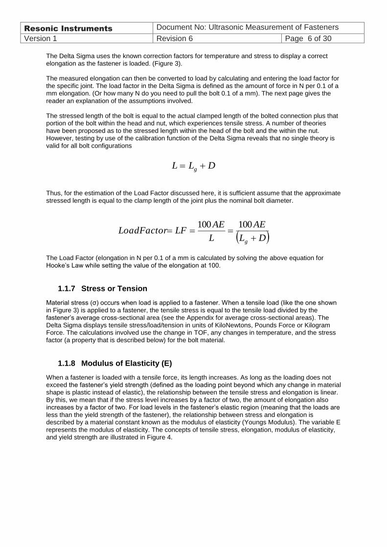
Version 1 Revision 6 Page 6 of 30 The Delta Sigma uses the known correction factors for temperature and stress to display a correct elongation as the fastener is loaded. (Figure 3). The measured elongation can then be converted to load by calculating and entering the load factor for the specific joint. The load factor in the Delta Sigma is defined as the amount of force in N per 0.1 of a mm elongation. (Or how many N do you need to pull the bolt 0.1 of a mm). The next page gives the reader an explanation of the assumptions involved. The stressed length of the bolt is equal to the actual clamped length of the bolted connection plus that portion of the bolt within the head and nut, which experiences tensile stress. A number of theories have been proposed as to the stressed length within the head of the bolt and the within the nut. However, testing by use of the calibration function of the Delta Sigma reveals that no single theory is valid for all bolt configurations
Thus, for the estimation of the Load Factor discussed here, it is sufficient assume that the approximate stressed length is equal to the clamp length of the joint plus the nominal bolt diameter.
The Load Factor (elongation in N per 0.1 of a mm is calculated by solving the above equation for Hooke’s Law while setting the value of the elongation at 100.
1.1.7 Stress or Tension
Material stress (σ) occurs when load is applied to a fastener. When a tensile load (like the one shown in Figure 3) is applied to a fastener, the tensile stress is equal to the tensile load divided by the fastener’s average cross-sectional area (see the Appendix for average cross-sectional areas). The Delta Sigma displays tensile stress/load/tension in units of KiloNewtons, Pounds Force or Kilogram Force. The calculations involved use the change in TOF, any changes in temperature, and the stress factor (a property that is described below) for the bolt material.
1.1.8 Modulus of Elasticity (E)
When a fastener is loaded with a tensile force, its length increases. As long as the loading does not exceed the fastener’s yield strength (defined as the loading point beyond which any change in material shape is plastic instead of elastic), the relationship between the tensile stress and elongation is linear. By this, we mean that if the stress level increases by a factor of two, the amount of elongation also increases by a factor of two. For load levels in the fastener’s elastic region (meaning that the loads are less than the yield strength of the fastener), the relationship between stress and elongation is described by a material constant known as the modulus of elasticity (Youngs Modulus). The variable E represents the modulus of elasticity. The concepts of tensile stress, elongation, modulus of elasticity, and yield strength are illustrated in Figure 4.
L L Dg
DL
AE
L
AELFLoadFactor
g
100100

Resonic Instruments Document No: Ultrasonic Measurement of Fasteners
Version 1 Revision 6 Page 7 of 30
Figure 4. This graph shows the relationship between tensile stress and elongation in a fastener.
1.1.9 Temperature Coefficient
The temperature of a fastener affects its physical length. But more importantly for our purposes, it affects the speed of sound in the material. As the temperature of a fastener increases, its physical length increases. In addition, as a fastener’s temperature increases, the amount of time it takes for sound to travel through the fastener also increases. In other words, when a fastener is subjected to increased temperature, its acoustic velocity decreases; therefore, its ultrasonic length increases. Temperature’s effect on ultrasonic length through changes in speed of sound is in an approx. 10:1 in effect on the measurement in comparison to thermal expansion/physical length. The thermal expansion of the fastener and the ultrasonic velocity change with temperature are two separate effects. However, the Delta Sigma is normally fitted with a temperature probe that automatically adjust the instrument according to the actual temperature of the fastener (with a real time reading)
1.1.10 Stress Factor
The velocity at which a longitudinal wave moves through an object is affected by stress. When a fastener is stretched, there are two influences on its ultrasonic length (as determined by multiplying the sound wave’s time of flight (TOF) by the constant value of acoustic velocity). First, the length of material through which the sound must travel increases. In addition, the fastener’s actual acoustic velocity decreases as stress increases. In other words, even when the stretching effect on the fastener’s physical length is ignored, tensile stress leads to an increase in the fastener’s ultrasonic length. In the Delta Sigma, a material constant known as the Stress Factor compensates for the effect stress has on the fastener’s actual acoustic velocity. Some confusion surrounds this effect. Consider the example shown in Figure 5 as you read the following description. In Figure 5(A), no load is applied to the fastener when the reference ultrasonic length (UL1) is recorded. In Figure 5B, a load is applied and a new ultrasonic length (UL2) is recorded. Note that Figure 5A and 5B also identify the physical length when unloaded (Physical Length 1) and loaded (Physical Length 2). The actual physical elongation of the fastener equals Physical Length 1 – Physical Length 2. The difference between the ultrasonic lengths (UL1 and UL2) is about three times the actual physical elongation of the fastener. It is important to note that in order to change the acoustic velocity, stress must be applied in the same direction travelled by the ultrasonic shock wave.

Resonic Instruments Document No: Ultrasonic Measurement of Fasteners
Version 1 Revision 6 Page 8 of 30 Thus, shear and torsional stress have no effect on the acoustic velocity when measured along the fastener’s length.
Figure 5. Applied tensile stress affects the ultrasonic (measured) length of a fastener in two ways
This explains and sums up the reasons why you cannot use conventional pulse-echo ultrasonic thickness gauges, flaw detectors or phased array systems to monitor bolt elongation or load.
1.1.11 Calibration Correction Factors — Stress Ratio, Offset & Calibration
The uncertainty of the Delta Sigma’s elongation measurement and subsequent uncertainty of displayed load involves a few factors. Two important influences on the uncertainty of these calculations are the material property constants and the fastener’s geometric characteristics. While the material-property constants (including elasticity, acoustic velocity, and stress factor) are considered to be standard values, actual material properties may vary pending quality of manufacturer material and process control. This variation is unfortunately also found among fasteners produced in the same manufacturer’s lot. The Delta Sigma’s uncertainty depends partly on the difference between the fastener’s actual material properties and those properties represented by the standard material constants. Along with variations in fastening systems’ physical characteristics that affects the accuracy of load and elongation calculations. When Delta Sigma users desire to display elongation and calculate load & stress values with a higher degree of accuracy, they generally choose to create calibration groups and test fasteners; comparing data from calibrated tensile testers while measuring elongation with the Delta Sigma. The Delta Sigma can use values of actual tensile load, to calculate correction factors. These correction factors are used to convert the Delta Sigma tension value into a corrected tension/stress by inputting an initial load offset. Generally, one can use two methods to determine a correction factor. The first method, called a regression correlation, uses a linear regression technique to determine the stress factor and offset. (Figure 6) The stress factor is actually the slope of a line that represents the relationship between actual elongation and calculated load. The stress offset represents the Y intercept of the actual verses calculated load line. This value can be thought of as the level to which actual load can increase before the Delta Sigma can measure an observable load. The second method used to determine correction factors is known as vector correlation. The value of the stress offset is set to zero. (Figure 6) When creating a calibration group, the user must decide which correction method to use. This decision should be based on the application. If accuracy over a wide range of loads (including low-level loads) is desirable, the vector correction is usually preferred. If the highest level of accuracy at a single target load is desired, the regression method is best and by far the most used. Why are two methods required? The relationship between actual and measured stress is often observed to be non-linear at

Resonic Instruments Document No: Ultrasonic Measurement of Fasteners
Version 1 Revision 6 Page 9 of 30 low loads (as shown in Figure 6). This can be caused by a skin effect. When a small amount of load is applied to a fastener, most of the stress is in the surface layers, not evenly distributed across the cross-section. Since the longitudinal wave travels predominantly down the centre of the fastener, less of the actual stress is observed
Figure 6. Calculated load
1.1.12 Fastener Geometry
Several geometrical characteristics of fasteners affect the ultrasonic measurement of load. Figure 7 briefly illustrates them.
Figure 7. Total length, effective length
1.2 Principles of Delta Sigma Operation.
The Delta Sigma measures the time it takes for a sound wave to travel through a fastener. The sound wave, more specifically known as an ultrasonic shock wave or longitudinal wave, is created in the transducer. The wave is generated when a large electric pulse is sent to the transducer from the instrument. This pulse excites a piezoelectric element in the transducer. The wave’s frequency varies with the thickness of the piezoelectric element. Frequencies most useful for measuring fasteners range from 1 to 10 MHz. This range of ultrasound will not travel in air. Couplant, which is usually a viscous liquid substance (usually propylene glycol, glycerine or oil) must be used to “couple” the transducer to the bolt providing a connection or pathway for the ultrasound to travel from the transducer into the fastener and back again.
DELTA SIGMA CALCULATED LOAD

Resonic Instruments Document No: Ultrasonic Measurement of Fasteners
Version 1 Revision 6 Page 10 of 30 When the ultrasonic wave encounters an abrupt change in material density, such as at the end of the fastener, most of the wave reflects. This reflection travels back the length of the fastener, through the layer of couplant, and back into the transducer. When the shock wave enters the piezoelectric element, a small electrical signal is produced. The Delta Sigma detects this signal. The Delta Sigma then measures the elapsed time between the sound entering the material and the returned signal. This elapsed time is known as the wave’s time of flight. Of course the time of flight actually represents the time taken by the wave to travel the length of the fastener two times. The TOF reported by the Delta Sigma equals half of this value. The Delta Sigma measures the elapsed time between two consecutive returning signals. The Delta Sigma then determines the ultrasonic length by first using the temperature coefficient to correct the TOF for any changes in temperature. The Delta Sigma then multiplies the corrected TOF by the fastener’s acoustic velocity. Acoustic velocity is represented in the Delta Sigma with the variable V and is determined by the fastener’s material type. The stress constant (K) and effective length are then used by the Delta Sigma logic to determine an uncorrected stress. As explained in Chapter 8, when the calibration-group feature is used, the stress ratio and offset are applied to this stress value to find a corrected stress. Since the actual acoustic velocity is not truly a constant, and can vary between fasteners of like material composition, the change in measured time of flight (recorded before and after each fastener is tensioned) must be used to accurately measure a fastener’s stress, load, and elongation. To determine the change in time of flight, the Delta Sigma first records a reference length by determining a normalized time of flight for a non-tensioned fastener. A normalized time of flight measurement of the same fastener, this time while tensioned, is then recorded. The two normalized TOF’s (which have already been corrected for the effects of temperature) are then used with the effective length, sonic stress factor, and acoustic velocity to determine the uncorrected stress.
1.2.1 Material Compatible with Ultrasonic Inspection
Most metals are excellent conductors of ultrasound. However, certain cast irons and materials like plastics normally absorb ultrasound and cannot be measured with the Delta Sigma.
1.2.2 Significant Fastener Stretch
Since ultrasonic techniques measure a fastener’s change in length, a significant amount of stretch is required to produce accurate measurements. Accuracy is a significant problem in applications where the effective length of a fastener is very short, such as a screw holding a piece of sheet metal. These applications may be poorly suited to ultrasonic measurement because the tensile load (and therefore tensile stress) is applied over a very short effective length of the fastener. Because the stressed length is so small, little or no measurable elongation of the fastener occurs. In the same way, it is difficult to measure the effects of very low loads. Negligible elongation occurs when tensile stress levels are less than about 10% of the material’s ultimate tensile stress. The small errors in measurement introduced by removing and replacing the transducer (as described in section 2.2) may become very significant when trying to measure such a small amount of elongation.
1.2.3 Fastener End-Surface Configuration
The ends of bolt heads and threaded sections (bolts or studs) should be manufactured to a minimum surface roughness and parallel finish. Or they may need to be prepared before the fastener is fit for optimal ultrasonic inspection. The fastener ends that will be mated with a transducer should be machined/finished to a flat and relatively smooth surface to allow for proper coupling of the transducer. The ideal finish for the transducer coupling point is between 32 to 63 micro inch CLA / 0.8 to 1.6 micrometre Ra. Similarly, the surface at the opposite end of the fastener (known as the reflective surface) should be parallel to the surface that supports the transducer. This parallelism allows the reflective surface to reflect the ultrasound back to the transducer. While the finish of the reflective surface is not as critical, very rough, uneven or irregular bolt ends can increase errors or render a bolt unmeasurable. Problems with surfaces can be indicated by poor signal quality on the waveform display.

Resonic Instruments Document No: Ultrasonic Measurement of Fasteners
Version 1 Revision 6 Page 11 of 30
2. Transducer Selection A wide variety of ultrasonic transducers are available. Suitability for a specific application is determined based on the transducer’s center frequency, diameter, and damping. However, because there is often a broad range of applications for which transducers are suitable, and these ranges often overlap, it can be difficult to pick the “best” transducer for a specific job. The best advice is always to test and gain experience with the specific materials and finish involved. In cases where it is difficult to place/mount a standard transducer; the glue-on transducer chips provide a very good alternative. The use of the glue-on transducer also removes the uncertainty of transducer placement.
2.1 General Acceptability
There is no single rule of thumb to follow when selecting a transducer for a specific application. For some fastening systems, many different types of transducers will measure with acceptable results. In the case of a hard-to-inspect fastener, transducer selection becomes more critical. One “experience rule” does however apply in terms of practical usage: Use the largest diameter transducer that will fit the bolt end while remaining concentric!
2.2 Transducer Frequency
A transducer’s frequency rating refers to the resonant frequency of the piezoelectric crystal. This is determined by the thickness of the crystal material. A thin crystal has a higher resonant frequency than a thick crystal. The frequency of the transducer affects the transmission of ultrasound in two different ways, beam width and absorption. The beam width (also referred to as directivity) identifies how dispersed the shock wave becomes as it travels over a specific distance. Beam width decreases (that is, the wave becomes more tightly focused) as transducer frequency increases. This means that a 10 MHz transducer has a tighter beam (with a lower beam width) than a 5 MHz version of the same transducer. A tightly focused beam is desirable since it allows more energy to reach the end of the fastener, making the noise that reflects off the thread and shank areas less of an issue. However, as frequency increases, the absorption of the ultrasound by the material also increases. Absorption refers to the material’s ability to absorb (rather than reflect) ultrasonic sound energy. It interferes with the shockwave, reducing the received signal’s resolution. Lower-frequency ultrasound travels around small flaws or voids within the fasteners without significant interference to the shock wave. In conclusion, lower transducer frequencies are better suited as fastener lengths increase and we have by experience and empirical testing concluded that 5 MHz transducers offer the best balance of benefits for most applications.
NOTE: It is recommended that the same style and model probe be used when taking zero-length (L-Ref) and none tensioned-fastener measurements of a fastener group. Furthermore, the most accurate results will be attained when the same probe (Same serial number) is used to make tensioned and non-tensioned measurements of a group of fasteners.
Resonic Instruments Document No: Ultrasonic Measurement of Fasteners
Version 1 Revision 6 Page 12 of 30
2.3 Transducer Diameter
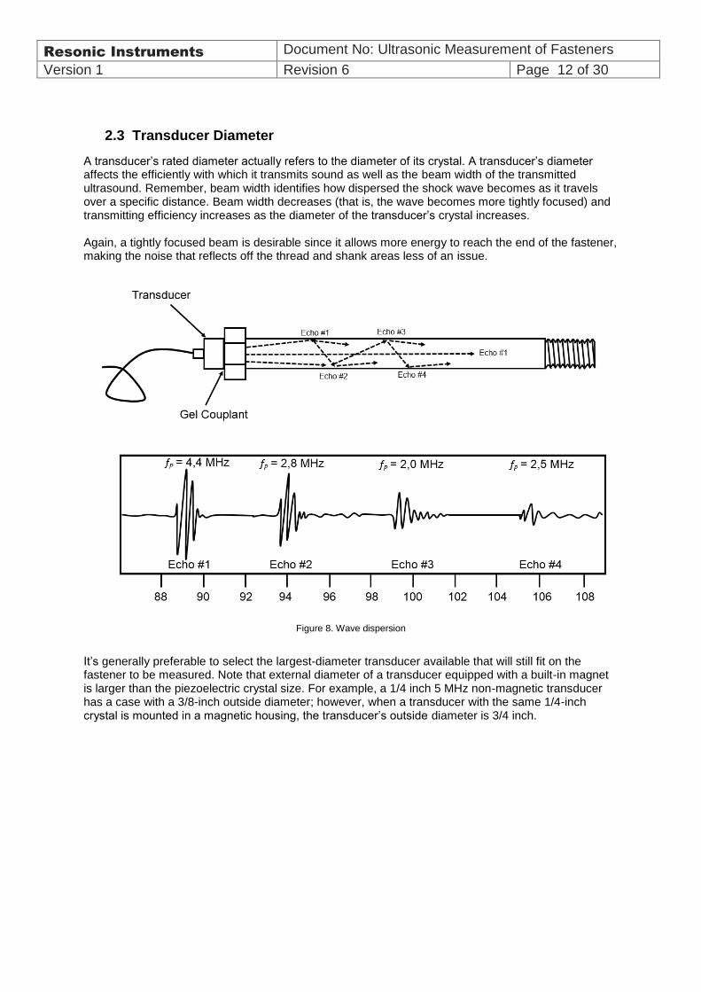
A transducer’s rated diameter actually refers to the diameter of its crystal. A transducer’s diameter affects the efficiently with which it transmits sound as well as the beam width of the transmitted ultrasound. Remember, beam width identifies how dispersed the shock wave becomes as it travels over a specific distance. Beam width decreases (that is, the wave becomes more tightly focused) and transmitting efficiency increases as the diameter of the transducer’s crystal increases. Again, a tightly focused beam is desirable since it allows more energy to reach the end of the fastener, making the noise that reflects off the thread and shank areas less of an issue.
Figure 8. Wave dispersion
It’s generally preferable to select the largest-diameter transducer available that will still fit on the fastener to be measured. Note that external diameter of a transducer equipped with a built-in magnet is larger than the piezoelectric crystal size. For example, a 1/4 inch 5 MHz non-magnetic transducer has a case with a 3/8-inch outside diameter; however, when a transducer with the same 1/4-inch crystal is mounted in a magnetic housing, the transducer’s outside diameter is 3/4 inch.

Resonic Instruments Document No: Ultrasonic Measurement of Fasteners
Version 1 Revision 6 Page 13 of 30
3. Fastener Geometry As explained throughout this guide, load calculations made by the Delta Sigma rely directly on user-input fastener dimensions and subsequent load factor calculation. A fastener’s material type, nominal length, average diameter, and effective length (also known as working length) must be input in order for the Delta Sigma to display load. While material types and the constants that define their properties are described in Chapter 7, this chapter deals with the geometric properties that define a fastener’s shape. Some of a fastener’s geometric properties have little effect on certain Delta Sigma calculations, while others have a significant effect. It is important to understand how each geometric property affects the Delta Sigma’s output and conversion of elongation to load.
3.1 Approximate Length
In the Delta Sigma, the approximate length is the total length of the fastener. In terms of ultrasonics, this is the distance from the ultrasonic transducer to the opposite (reflecting) end of the fastener. The approximate length is used to determine the distance at which the Delta Sigma’s receiver is enabled. While the accuracy of the quantity entered for total fastener length does not affect the accuracy of the Delta Sigma readings, entering a significantly incorrect value for total length may result in unstable or no readings at all. If the value entered for approximate length is too large, the first echo that returns from the bolt may be ignored. If the value entered for approximate length is too short, the Delta Sigma will not detect the correct returning echo.
3.2 Determining Effective Length
When a fastening system is tensioned, the length of the fastener to which the tensile load is applied is known as its effective length. When considering a constant applied load, the amount of fastener elongation is directly proportional to a fastener’s effective length. In other words, if two fastening systems are identical in all ways, including the tensile load on the fastener, except that the effective length of the first fastener is twice the effective length of the second, then the elongation of the first fastener will be twice the elongation of the second. However, the accuracy of the value entered for effective length has a direct influence on the accuracy of measured stress and load. If the value entered for effective length is ten percent less than the actual value, the error in load and stress measurements will be ten percent. The effective length is calculated differently depending on the fastener application. The directions for calculating the effective length in four different cases are outlined in Figures 9 through 12. Note that the resulting values for effective length are approximate and may vary due to certain other factors. For example, consider an application using a bolt in a blind hole. Suppose the material strength of the bolt is greater than the threaded hole. The weaker threads in the hole will flex more than the threads of the bolt, and the effective length will be longer than if the materials were of the same material. For the best accuracy of load or stress readings, calibrate the Delta Sigma for the specific application. This will cancel errors due to effective length uncertainty. In this approach a calibration group is formed (using fasteners that are the same or similar to the ones being tested). The fasteners are inserted in a fixture that loads them at the same effective length with a known quantity of load.

Resonic Instruments Document No: Ultrasonic Measurement of Fasteners
Version 1 Revision 6 Page 14 of 30 The figures show:
• Stud fastening system (Figure 9) • Through bolt fastening system (Figure 10) • Bolt (screw) turned into a threaded hole (Figure 11) • Stud turned into a threaded hole (Figure 12)
Figure 9. This is a typical stud configuration. The effective length of a stud with nuts on each
end is found by adding the stud diameter to the clamp length
Figure 10. This is a typical through bolt configuration. The effective length of a bolt with a single nut is found
by adding half the diameter to one-third the diameter (5/6 of the diameter total) to the clamp length.
Figure 11. This is typical of a configuration with a bolt (screw) turned into a threaded hole. When a headed fastener is
threaded into a metal block, such as an automotive head bolt, calculate the effective length by adding half the diameter to one third the diameter (5/6 of the diameter total), then adding this amount to the clamp length.

Resonic Instruments Document No: Ultrasonic Measurement of Fasteners
Version 1 Revision 6 Page 15 of 30
Figure 12. This is typical of a configuration with a stud turned into a threaded hole. When a stud is threaded into a blind hole and a nut is placed on the opposite end, find the effective length by adding the stud diameter to the clamp length.
3.3 Fastener Cross-Sectional Area
The cross-sectional area is the average area of that portion of a fastener that is subjected to tensile loading. In other words, it’s an average cross-sectional area taken over only the fastener’s effective length. The cross sectional area in threaded portions of the fastener should be calculated based on the thread’s minor diameter. The accuracy with which cross-sectional area is entered only affects the Delta Sigma load calculation. It has no effect on the stress or elongation measurement. The accuracy of the value entered for cross-sectional area has a direct influence on the accuracy of measured load. If the value entered for cross-sectional area is ten percent less than the actual value, then the measured value of load will be ten percent lower than the actual value. If a fastener’s geometry is more complex, with varying values of cross-sectional area along its effective length, the various areas over the effective length may be aver aged to arrive at an overall average cross-sectional area. In the case of a hollow fastener, the area of the hole must be subtracted from the overall average cross-sectional area to determine the actual cross sectional area. To calculate the average cross-sectional area of a fastener, multiply the length of each segment along the effective length of the fastener by the cross-sectional area of each specific segment. (Figure 13)
Figure 13. Follow this procedure to determine the average cross-sectional area over the effective length of an irregular fastener.
Add all of the resulting values, and then divide the total by the sum of the lengths. In the appendix of this manual, you will find tables of average cross-sectional areas for various types and sizes of common fastener. For the best accuracy of load readings, calibrate the Delta Sigma for the specific length. This will cancel errors due to cross sectional area uncertainty. In this approach a calibration group is formed (using fasteners that are the same or similar to the ones being tested). The fasteners are inserted in a fixture that loads them at the same effective length with a known quantity of load.

Resonic Instruments Document No: Ultrasonic Measurement of Fasteners
Version 1 Revision 6 Page 16 of 30
4. Fastener Preparation
Prior to measuring a fastener, it is recommended that it is prepared for ultrasonic inspection. The fastener ends may be machined to be parallel, and the end that will be mated with a transducer may benefit from being finished with a smooth surface. Further; to allow for proper coupling of the transducer and fastener, a suitable couplant must be applied. Finally, consistent placement of the transducer on the bolt head or stud end improves the instrument’s accuracy and repeatability. Hence it may be beneficial to make bolts that has a larger than standard transducer size, with a dedicated measuring groove.
4.1 Fastener End-Surface Machining
The ends of bolt heads and threaded sections (bolts or studs) will benefit from preparation before the ultrasonic inspection. The fastener end that will be mated with a transducer should be as perpendicular as possible to the fastener’s centre line and ideally be machined to a very flat, smooth surface to allow for proper coupling of the transducer. The ideal finish for the transducer coupling point is between 32 to 63 min. CLA (0.8 to 1.6 mm Ra). Inadequate surface finishes are indicated by poor signal quality on the display the reflective surface at the opposite end of the fastener must be parallel to the surface that mates with the transducer. The degree to which these two surfaces are machined parallel determines the upper limit of an ultrasonic inspection system’s uncertainty of repetitive measurement
While the surface finish of the reflective surface is not as critical, very rough or uneven finish can produce errors. Use care when machining fastener ends. A common problem occurs when a small peak is left in the centre of a fastener end after facing on a lathe. This small bump prevents the transducer from achieving proper contact and greatly reduces the signal amplitude.
4.2 Methods of Transducer Placement
Unless fastener ends and transducer surfaces are parallel, the reflected ultrasonic signal may vary with changes in the transducer’s orientation, with respect to the fastener. Optimal repeatability and accuracy are achieved by leaving the transducer attached to the fastener, in exactly the same location and angular orientation, throughout the tensioning process. As this ideal approach is often not possible or practical, the next best practice is to consistently return the transducer to the same location and angular orientation, with respect to the fastener. This practice improves the chances that the path followed by the shock wave when the reference length was measured is identical (or close to identical) to the path followed after the fastening system is tightened The alternative is to use Glue-On transducers which will only require a measurement pin probe and it is independent upon transducer placement.
NOTE: Most fastener materials are excellent conductors of ultrasound. However, certain cast irons and many plastics absorb ultrasound and cannot be measured with the Delta Sigma

Resonic Instruments Document No: Ultrasonic Measurement of Fasteners
Version 1 Revision 6 Page 17 of 30
4.2.1 Practical Methods
Several practical methods are used to ensure consistent transducer placement. The most common method utilizes a magnetic transducer, which is placed in the centre of the bolt’s head. Step 1: First measure the reference (non-tensioned) length by coupling the transducer to the fastener end and adjusting its orientation and centre using remove & replace routine. Step 2: Mark the transducer location and angular orientation on the fastener end if possible. Step 3: Continue with the fastener tightening procedure. If possible, the transducer can remain connected to the fastener end in exactly the same position and orientation. If this is not possible, proceed to step 4.
Step 4: Before proceeding, reconfirm that the position marked on the fastener end remains the location that returns the greatest-amplitude waveform and the shortest length. This step is important because in some cases, as the fastener is tensioned, a small amount of bending occurs.
When bending occurs, the angular orientation that returns the maximum-amplitude waveform may change. If the maximum-response location has changed, adjust the position of the transducer to the new location on the bolt head. This assures the optimum sound path is being used, both before and after tightening. Step 5: Position the transducer in the marked location (or at the newly identified maximum-amplitude location) to continue recording tensioned readings. Avoid:
Rough or irregular surfaces, which prevent adequate contact with the transducer. Energy will ricochet off the sidewalls. Small irregularities or surface roughness can be filled with couplant, but energy transmission will still be reduced and dispersed, as shown in Figure 15(A)
Bolt ends not perpendicular to the axis of the bolt, as shown in Figure 15(B). Energy will be transmitted toward the side wall and ricochet along the bolt, yielding poor signal quality and possible measurement errors. Avoid alignment errors exceeding 2 degrees.
Figure 15. Transducer placement
Rusted, dirty, or thick paint-covered bolt ends. These coatings prevent sonic energy from traveling between the transducer and the bolt. Very thin well-adhered coating or plating is acceptable.
A B
Figur 14. Bending signal
Resonic Instruments Document No: Ultrasonic Measurement of Fasteners
Version 1 Revision 6 Page 18 of 30
Bolt ends with recessed grade marks, as shown in Figure 15. Couplant can be used to fill small recessed grade marks. Small indentations cause some loss of signal strength, but normal measurement is still possible. Large or numerous indentations cause the signal to be too weak for reliable measurement.
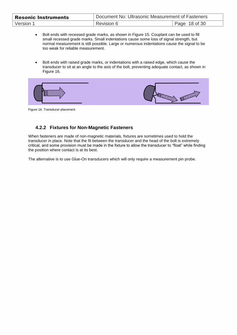
Bolt ends with raised grade marks, or indentations with a raised edge, which cause the transducer to sit at an angle to the axis of the bolt, preventing adequate contact, as shown in Figure 16.
Figure 16. Transducer placement
4.2.2 Fixtures for Non-Magnetic Fasteners
When fasteners are made of non-magnetic materials, fixtures are sometimes used to hold the transducer in place. Note that the fit between the transducer and the head of the bolt is extremely critical, and some provision must be made in the fixture to allow the transducer to “float” while finding the position where contact is at its best. The alternative is to use Glue-On transducers which will only require a measurement pin probe.

Resonic Instruments Document No: Ultrasonic Measurement of Fasteners
Version 1 Revision 6 Page 19 of 30
Appendix A
MATERIALOF
BOLT
SONIC STRESS FACTOR
TEMPERATURE FACTOR
SOUND VELOCITY
MODULUS OF ELASTICITY
F C IN / SEC MM / SEC PSI X 10 6 Mpa X 10 3
ISO SPECIFICATIONS R898
Gr.8.8
Gr.9.8
Gr.10.9
Gr.12.9
0.276
0.276
0.274
0.274
58
58
57
57
104
104
103
103
232000
232000
232000
232000
5890000
5890000
5890000
5890000
29.9
29.9
29.9
29.9
205
205
205
205
MATERIAL SPECIFICATIONS
4140 STEEL
4340 STEEL
STS STEEL
INCONEL
TITANIUM
0.274
0.285
0.250
0.296
0.490
56
55
80
62
64
101
99
144
111
115
232000
232000
230000
225000
245000
5890000
5890000
5840000
5710000
6220000
29.9
30
29
31
16.5
205
207
200
214
114
ASTM SPECIFICATIONS
A193 B7
A193 B16
A325
A490
A540
0.280
0.280
0.274
0.299
0.299
57
57
56
60
60
103
103
101
108
108
232000
232000
232000
232000
232000
5890000
5890000
5890000
5890000
5890000
30
30
29.9
29.9
30
207
207
205
205
207
SAE SPECIFICATIONS 1038
Gr.2
Gr.5
Gr.6
Gr.8
Gr.9
0.275
0.275
0.277
0.274
0.275
57
57
60
57
58
103
103
108
103
104
232000
232000
232000
232000
232000
5890000
5890000
5890000
5890000
5890000
29.9
29.9
29.9
29.9
29.9
205
205
205
205
205
Note: These are approximate values and should only be used when accuracy+/- 10% is acceptable.
Resonic Instruments Document No: Ultrasonic Measurement of Fasteners
Version 1 Revision 6 Page 20 of 30
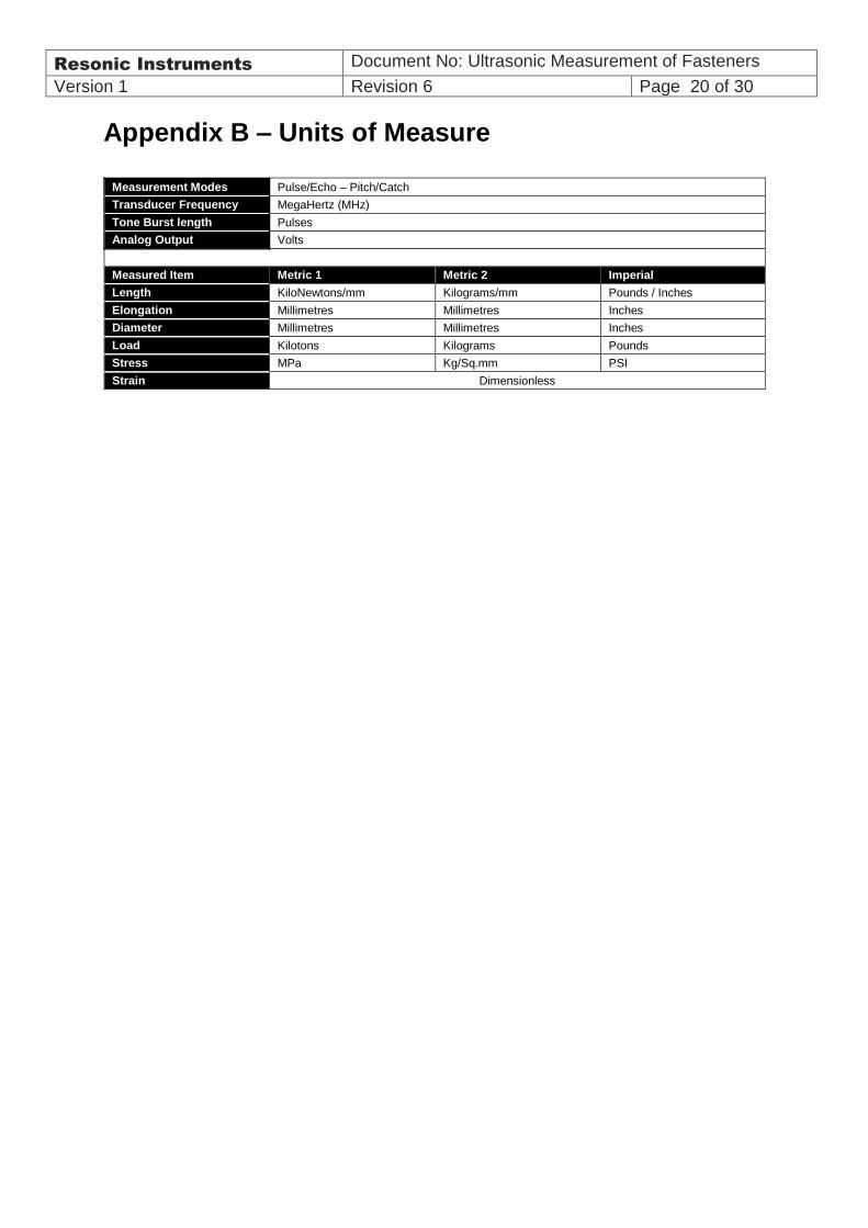
Appendix B – Units of Measure
Measurement Modes Pulse/Echo – Pitch/Catch
Transducer Frequency MegaHertz (MHz)
Tone Burst length Pulses
Analog Output Volts
Measured Item Metric 1 Metric 2 Imperial
Length KiloNewtons/mm Kilograms/mm Pounds / Inches
Elongation Millimetres Millimetres Inches
Diameter Millimetres Millimetres Inches
Load Kilotons Kilograms Pounds
Stress MPa Kg/Sq.mm PSI
Strain Dimensionless
Resonic Instruments Document No: Ultrasonic Measurement of Fasteners
Version 1 Revision 6 Page 21 of 30
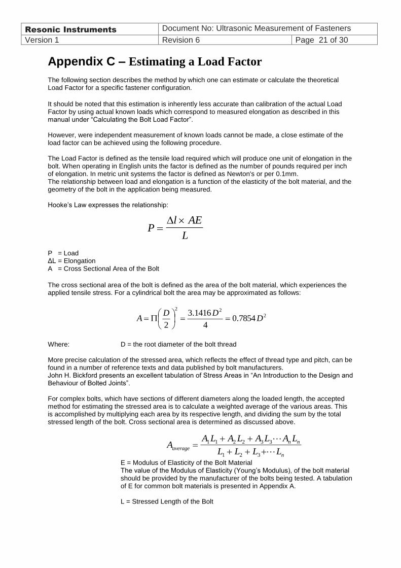
Appendix C – Estimating a Load Factor The following section describes the method by which one can estimate or calculate the theoretical Load Factor for a specific fastener configuration.
It should be noted that this estimation is inherently less accurate than calibration of the actual Load Factor by using actual known loads which correspond to measured elongation as described in this manual under “Calculating the Bolt Load Factor”. However, were independent measurement of known loads cannot be made, a close estimate of the load factor can be achieved using the following procedure. The Load Factor is defined as the tensile load required which will produce one unit of elongation in the bolt. When operating in English units the factor is defined as the number of pounds required per inch of elongation. In metric unit systems the factor is defined as Newton's or per 0.1mm. The relationship between load and elongation is a function of the elasticity of the bolt material, and the geometry of the bolt in the application being measured. Hooke’s Law expresses the relationship:
P = Load ΔL = Elongation A = Cross Sectional Area of the Bolt
The cross sectional area of the bolt is defined as the area of the bolt material, which experiences the applied tensile stress. For a cylindrical bolt the area may be approximated as follows:
Where: D = the root diameter of the bolt thread More precise calculation of the stressed area, which reflects the effect of thread type and pitch, can be found in a number of reference texts and data published by bolt manufacturers. John H. Bickford presents an excellent tabulation of Stress Areas in “An Introduction to the Design and Behaviour of Bolted Joints”. For complex bolts, which have sections of different diameters along the loaded length, the accepted method for estimating the stressed area is to calculate a weighted average of the various areas. This is accomplished by multiplying each area by its respective length, and dividing the sum by the total stressed length of the bolt. Cross sectional area is determined as discussed above.
E = Modulus of Elasticity of the Bolt Material The value of the Modulus of Elasticity (Young’s Modulus), of the bolt material should be provided by the manufacturer of the bolts being tested. A tabulation of E for common bolt materials is presented in Appendix A. L = Stressed Length of the Bolt
Pl AE
L
222
7854.04
1416.3
2D
DDA
AA L A L A L A L
L L L Laverage
n n
n
1 1 2 2 3 3
1 2 3

Resonic Instruments Document No: Ultrasonic Measurement of Fasteners
Version 1 Revision 6 Page 22 of 30
The stressed length of the bolt is equal to the actual clamped length of the bolted connection plus that portion of the bolt within the head and nut, which experiences tensile stress. A number of theories have been proposed as to the stressed length within the head of the bolt and the within the nut. However testing by use of the calibration function of the Delta Sigma reveals that no single theory is valid for all bolt configurations.
Thus, for the estimation of the Load Factor discussed here, it is sufficient assume that the approximate stressed length is equal to the clamp length of the joint plus the nominal bolt diameter. The Load Factor (elongation in N per 0.1 of a mm is calculated by solving the above equation for Hooke’s Law while setting the value of the elongation at 10.
Worked example for a bolted joint in Metric units: Data: M20 x 2,5: ISO 8.8 Stud Bolt with and 200 mm effective length (clamp length + nuts & washers): E (Youngs Modulus) for 8.8 = 206,15 kN/ mm² A (Iso for M20) = 245 mm² L- Effective length = 200 mm
Hence the load factor entered into the DS for this bolt joint example would be: 25333
L L Dg
DL
AE
L
AELFLoadFactor
g
100100
mmkNmmNxx
LFLoadFactor /3,2531.0/25333200
)15,206245(100
Resonic Instruments Document No: Ultrasonic Measurement of Fasteners
Version 1 Revision 6 Page 23 of 30
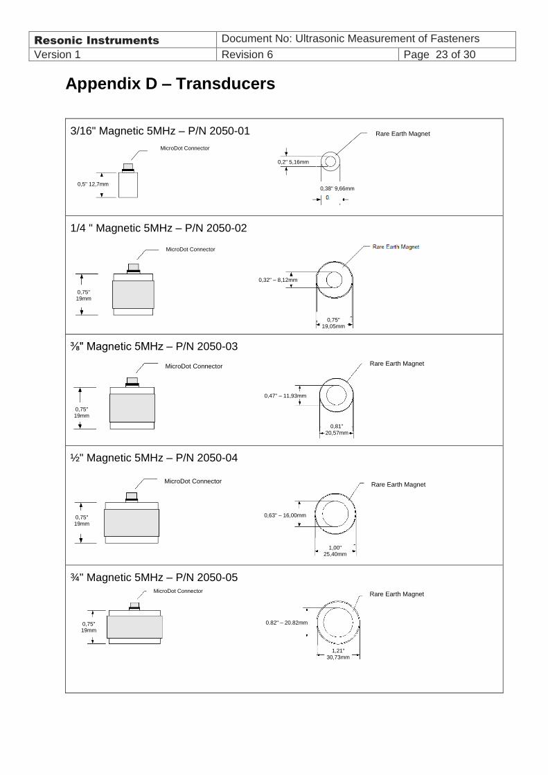
Appendix D – Transducers
3/16" Magnetic 5MHz – P/N 2050-01
1/4 " Magnetic 5MHz – P/N 2050-02Magnetic 5MHz – P/N 2050-02
⅜" Magnetic 5MHz – P/N 2050-03
½" Magnetic 5MHz – P/N 2050-04
¾" Magnetic 5MHz – P/N 2050-05
0,75" 19mm
MicroDot Connector
0,32" – 8,12mm
0,75" 19,05mm
Rare Earth Magnet
0,75" 19mm
MicroDot Connector
0,47" – 11,93mm
0,81"
20,57mm
0,75" 19mm
MicroDot Connector
0,63" – 16,00mm
Rare Earth Magnet
1,00" 25,40mm
Rare Earth Magnet
0,75" 19mm
MicroDot Connector
0,82" – 20,82mm
1,21"
30,73mm
0,5" 12,7mm
MicroDot Connector
Rare Earth Magnet
0,2" 5,16mm
0,38" 9,66mm

Resonic Instruments Document No: Ultrasonic Measurement of Fasteners
Version 1 Revision 6 Page 24 of 30
3x3mm Glue-on transducers – P/N 3000-01
The glue-on transducers comes in sheets of 100 transducers. They are simply glued-on the bolts and tested by using the 4000-TC or 4000-RH cable.

Resonic Instruments Document No: Ultrasonic Measurement of Fasteners
Version 1 Revision 6 Page 25 of 30
Appendix E – Temperature Factor The following section presents the procedure for experimental determination of the Temperature Factor for a bolt made of a specific bolt material and having specific geometry.
To carry out the test, one needs means of varying, and measuring the temperature of the sample bolts
between 0 to 100 C /32 to 212 F to an accuracy of 0,5C . The device must allow contact of the end of the sample bolt by the ultrasonic transducer. Many sophisticate temperature chambers are commercially available, and ideally suited for this function. However, a simple and inexpensive method can be achieved by immersion of the sample bolts in a water bath, which can be heated to boiling or cooled by adding ice. At sea level this will
reliably vary the bolt temperature between approximately 100 and 0 C depending on water purity and atmospheric pressure. By measuring the temperature of the stirred water bath with a precise mercury thermometer, while reading the ultrasonic length of the bolt, accurate calibration points can be obtained. In order to perform these experiments you need the following:
An Ultrasonic Stress Meter – Delta Sigma
A minimum of three sample bolts, which are representative of the bolt type and geometry for which the temperature factor is to be determined.
NOTES: Determination of the Temperature Factor is accomplish by solving the equation: Where:
L0 = Ultrasonic Length at Beginning Temperature (T0)
LT = Ultrasonic Length at Ending Temperature (T) T0 = Beginning Temperature T = Temperature at Present Measurement Point Acquire data as follows: 1. Stabilize the sample bolt at approximately 00 C/320 F. If the water bath method is used this is
accomplished in a stirred bath of ice and water. 2. Measure and record this minimum temperature as T0. 3. Using the DS in the “Unloaded Length” measurement mode, measure the ultrasonic length “L0” of
the sample bolt at the above minimum temperature. 4. Increase the temperature of the sample bolt to approximately 200 C/680 F. 5. Measure and record the exact temperature at this measurement point as T1. 6. Using the DS in the “Unloaded Length” measurement mode, measure and record the ultrasonic
length “L1” of the sample bolt at temperature T1.
7. Increase the temperature of the sample bolt to approximately 40 C / 104 F. 8. Measure and record the exact temperature at this measurement point as T2. 9. Using a bolt gauge in the “Unloaded Length” measurement mode, measure and record the
ultrasonic length “L2” of the sample bolt at temperature T2.
10. Increase the temperature of the sample bolt to approximately 60 C/140 F. 11. Measure and record the exact temperature at this measurement point as T3.
Note:
The sample bolts should be left to soak at the measured temperature points for a period of not less than 20 minutes, to insure that temperature is uniform throughout the sample.
If a water bath is used, care must be taken to avoid immersion of the ultrasonic transducer.
FactorInstrumentTTL
LLeFactorTemperatur
T
T
)(
)(
0
0

Resonic Instruments Document No: Ultrasonic Measurement of Fasteners
Version 1 Revision 6 Page 26 of 30 12. Using the sonic meter in the “Unloaded Length” measurement mode, measure and record the
ultrasonic length “L3” of the sample bolt at temperature T3.
13. Increase the temperature of the sample bolt to approximately 80 C/176 F. 14. Measure and record the exact temperature at this measurement point as T4. 15. Using a bolt gauge in the “Unloaded Length” measurement mode, measure and record the
ultrasonic length “L4” of the sample bolt at temperature T4.
16. Increase the temperature of the sample bolt to approximately 212 F (100 C). 17. Measure and record the exact temperature at this measurement point as T5. 18. Using the bolt gauge in the “Unloaded Length” measurement mode, measure and record the
ultrasonic length “L5” of the sample bolt at temperature T5. 19. Repeat steps 1 through 18 for the second and third sample bolt. 20. By solving the above equation calculate the Temperature Factor for each data point on each
sample bolt.
AND SO ON FOR EACH SAMPLE BOLT
Determine the average value of the Temperature Factor by dividing the sum of all TF values calculated by the total number of TF values
The above data collection and calculations can be performed easily by use of a spreadsheet.
IFTTL
LLTF TB
)(
)(
101
1011
IFTTL
LLTF TB
)(
)(
202
2021
12
43312111 TBTBTBTB
AVERAGE
TFTFTFTFTF

Resonic Instruments Document No: Ultrasonic Measurement of Fasteners
Version 1 Revision 6 Page 27 of 30
Appendix F –Sonic Stress Factor
The following describes a procedure by which the Sonic Stress Factor can be calculated by measurement of the applied load. It must be noted that this procedure is inherently less accurate than the measurement of actual change in bolt length, as described earlier. The uncertainty results from the calculation of theoretical change in bolt length under applied load. This calculation, which is the expression of Hooke’s Law, requires assumptions as to the effective, or working length, and the stressed cross-sectional area of the bolt, as well as the Modulus of Elasticity of the bolt material. Therefore the final calculation of the Stress factor will be only as accurate as those assumptions. It is therefore recommended be used only where apparatus for measurement of length is not available, and where bolt geometry allows reasonably accurate estimation of effective length and cross-sectional area.
As discussed in Part 1 the equation for the Sonic Stress Factor is:
In this procedure we will be measuring the change in Ultrasonic Length. However, we will be calculating the change in Mechanical Length (Elongation) by use of Hooke’s Law:
Where:
P = Applied Load
L = Effective Length (Normally the clamping length + one diameter) A = Cross-sectional Area of the Stressed Portion of the Bolt E = Modulus of Elasticity of the Bolt Material (Young’s Modulus) Estimate the value of L, A, as accurately as possible given the bolt geometry. The value of E is published for virtually all materials. The values for common bolt materials a presented in Appendix A. Acquire data as follows:
Using the Delta Sigma in the unloaded length measurement mode, measure and record the Ultrasonic Length at Zero Load “LU0” for each sample bolt.
Place the first sample bolt in the loading apparatus.
Apply approximately and record 1/3 of the Maximum load, which is to be placed on the bolt under actual working conditions. “P1”
Using the DS in the unloaded length measurement mode, measure and record the Ultrasonic Length at Load 1 “LU1”for the current sample bolt.
Increase and record the applied load to approximately 2/3 of the Maximum load, which is to be placed on the bolt under actual working conditions.”P2”
Using the DS in the unloaded length measurement mode, measure and record the Ultrasonic Length at Load 2 “LU2”for the current sample bolt.
Increase and record the applied load to approximately the Maximum load, which is to be placed on the bolt under actual working conditions. “P3”
0UUl
MECHANICAL
ULTRASONIC
MECHANICAL
LL
L
L
LsFactorSonicStres
LPL
AE
L L ElongationMECHANICAL
Note: Ultrasonic measurements will be more easily accomplished, and more accurate, if the transducer remains undisturbed on the bolt throughout the loading process.

Resonic Instruments Document No: Ultrasonic Measurement of Fasteners
Version 1 Revision 6 Page 28 of 30
Using the DS in the unloaded length measurement mode, measure and record the Ultrasonic Length at Load 3 “LU3”for the current sample bolt.
Repeat steps 4 through 12 for the second and third sample bolt.
Calculate the value of the Sonic Stress Factor at each load on each sample bolt
AND SO ON FOR EACH SAMPLE BOLT
Determine the average value of the Sonic Stress Factor by dividing the sum of all SSF values calculated by the total number of SSF values
The above data collection and calculations can be performed easily by use of a spreadsheet.
SSFP L
L L AEB L
U U
1 1
1
1 0
( )
SSFP L
L L AEB L
U U
1 3
3
3 0
( )
9
33312111 LBLBLBLB
AVERAGE
SSFSSFSSFSSFSSF
SSFP L
L L AEB L
U U
1 2
2
2 0
( )

Resonic Instruments Document No: Ultrasonic Measurement of Fasteners
Version 1 Revision 6 Page 29 of 30
Appendix G – Tabular Data Examples of Stress Area
(Please see VDI 2230 or ISO for updated Table Data on Metric Fasteners)
Metric Standard Thread Metric Fine Thread
Sizes mm Pitch mm Tensile
Stress Area Sq.mm
Sizes mm Pitch mm
Tensile Stress Area
Sq.mm
M4 0,7 8,78 M8 1,0 39,2
M5 0,8 14,2 M9 1,0 51
M6 1,0 20,1 M10 1,0 64,5
M7 1,0 28,9 M10 1,25 61,2
M8 1,25 36,6 M12 1,25 92,1
M10 1,5 58,0 M12 1,5 88,1
M12 1,75 84,3 M14 1,5 125
M14 2,0 115 M16 1,5 167
M16 2,0 157 M18 1,5 216
M18 2,5 193 M18 2,0 204
M20 2,5 245 M20 1,5 272
M22 2,5 303 M22 1,5 333
M24 3,0 353 M24 1,5 401
M27 3,0 459 M24 2,0 384
M30 3,5 561 M27 1,5 514
M33 3,5 694 M27 2,0 496
M36 4,0 817 M30 1,5 642
M39 4,0 976 M30 2,0 621
M33 1,5 784
M33 2,0 761
M36 1,5 940
M36 3,0 865
M39 1,5 1110
M39 3,0 1028
Resonic Instruments Document No: Ultrasonic Measurement of Fasteners
Version 1 Revision 6 Page 30 of 30
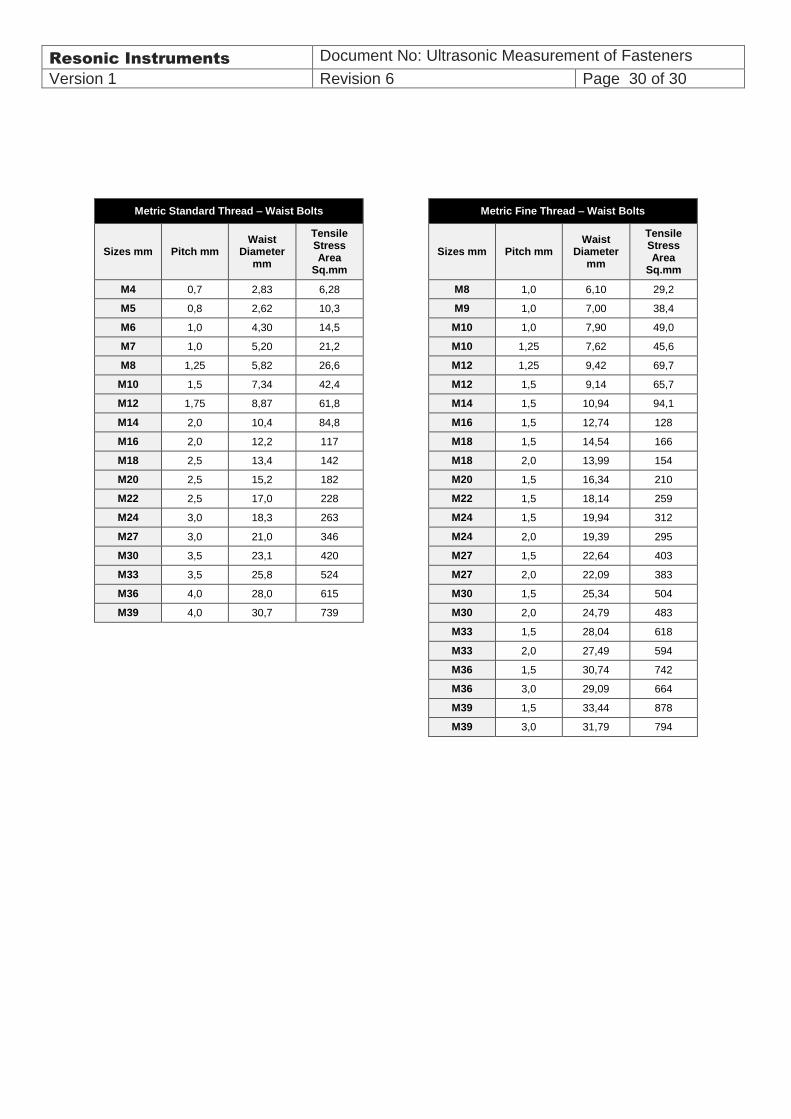
Metric Standard Thread – Waist Bolts Metric Fine Thread – Waist Bolts
Sizes mm Pitch mm Waist
Diameter mm
Tensile Stress Area
Sq.mm
Sizes mm Pitch mm
Waist Diameter
mm
Tensile Stress Area
Sq.mm
M4 0,7 2,83 6,28 M8 1,0 6,10 29,2
M5 0,8 2,62 10,3 M9 1,0 7,00 38,4
M6 1,0 4,30 14,5 M10 1,0 7,90 49,0
M7 1,0 5,20 21,2 M10 1,25 7,62 45,6
M8 1,25 5,82 26,6 M12 1,25 9,42 69,7
M10 1,5 7,34 42,4 M12 1,5 9,14 65,7
M12 1,75 8,87 61,8 M14 1,5 10,94 94,1
M14 2,0 10,4 84,8 M16 1,5 12,74 128
M16 2,0 12,2 117 M18 1,5 14,54 166
M18 2,5 13,4 142 M18 2,0 13,99 154
M20 2,5 15,2 182 M20 1,5 16,34 210
M22 2,5 17,0 228 M22 1,5 18,14 259
M24 3,0 18,3 263 M24 1,5 19,94 312
M27 3,0 21,0 346 M24 2,0 19,39 295
M30 3,5 23,1 420 M27 1,5 22,64 403
M33 3,5 25,8 524 M27 2,0 22,09 383
M36 4,0 28,0 615 M30 1,5 25,34 504
M39 4,0 30,7 739 M30 2,0 24,79 483
M33 1,5 28,04 618
M33 2,0 27,49 594
M36 1,5 30,74 742
M36 3,0 29,09 664
M39 1,5 33,44 878
M39 3,0 31,79 794