ultrasonic phased -array for aircraft maintenance maintenance.pdf7 equipment – omniscan mx-pa...
TRANSCRIPT

Ultrasonic phased-array for aircraft maintenance
Andre Lamarre
Amsterdam, November 2009

2
Presentation plan– Principle review of ultrasonic phased-array– Boeing 737: Scribe line inspection– Airbus 320: Inspection of wing top skin panel for
corrosion– Airbus 380 GLARE inspection with ultrasonic
phased-array– Composite inspection– F-5, T-38: Automated Fastener holes inspection
scanner
3
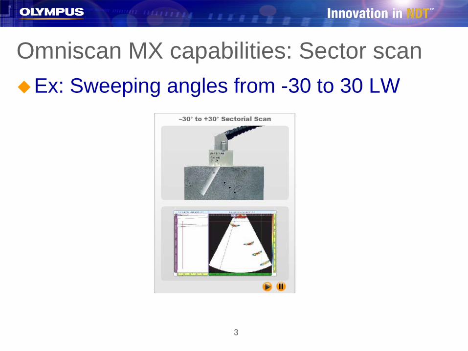
Omniscan MX capabilities: Sector scanEx: Sweeping angles from -30 to 30 LW

4
Ex: Sweeping angles from 35 to 70 SW
Omniscan MX capabilities: Sector scan
5
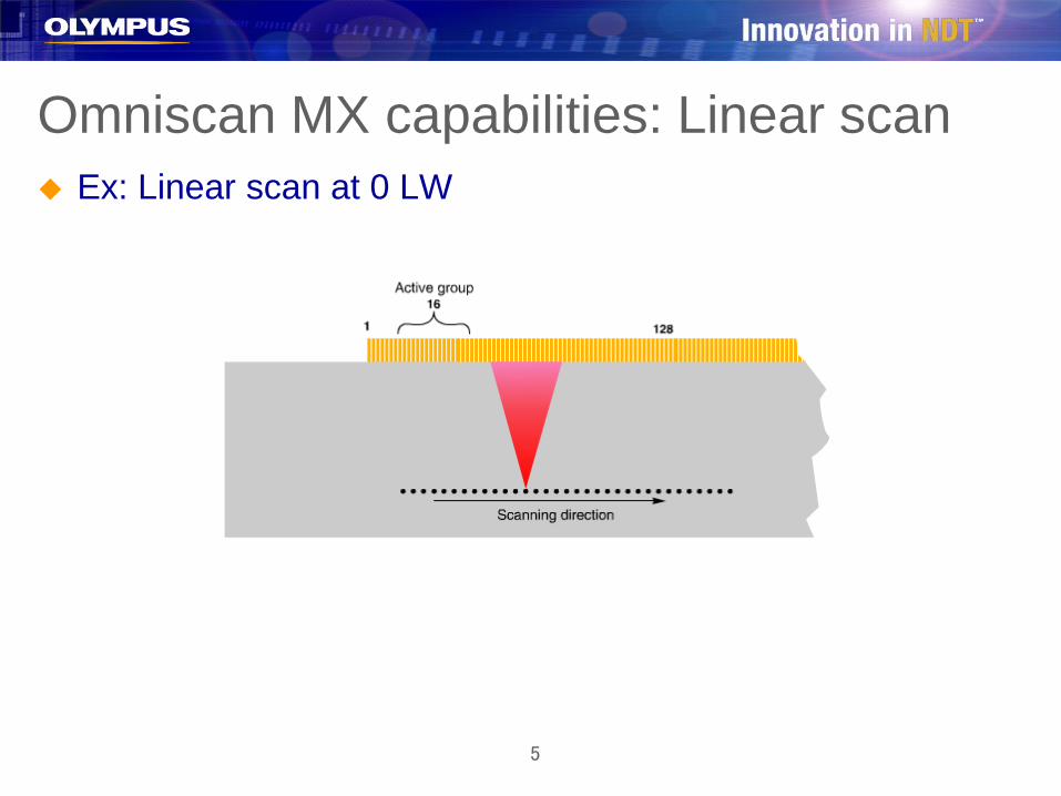
Ex: Linear scan at 0 LW
Omniscan MX capabilities: Linear scan
6
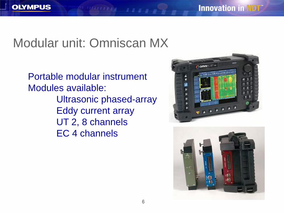
Modular unit: Omniscan MX
Portable modular instrumentModules available:
Ultrasonic phased-arrayEddy current arrayUT 2, 8 channelsEC 4 channels
7
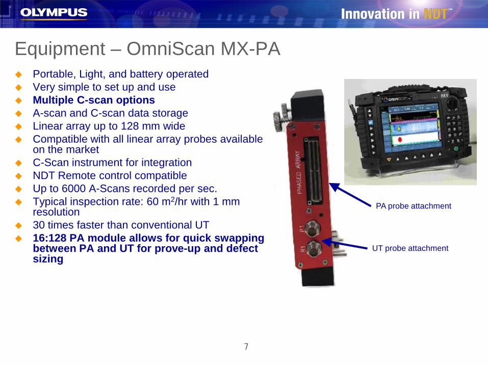
Equipment – OmniScan MX-PA Portable, Light, and battery operated Very simple to set up and use Multiple C-scan options A-scan and C-scan data storage Linear array up to 128 mm wide Compatible with all linear array probes available
on the market C-Scan instrument for integration NDT Remote control compatible Up to 6000 A-Scans recorded per sec. Typical inspection rate: 60 m2/hr with 1 mm
resolution 30 times faster than conventional UT 16:128 PA module allows for quick swapping
between PA and UT for prove-up and defect sizing
PA probe attachment
UT probe attachment
8
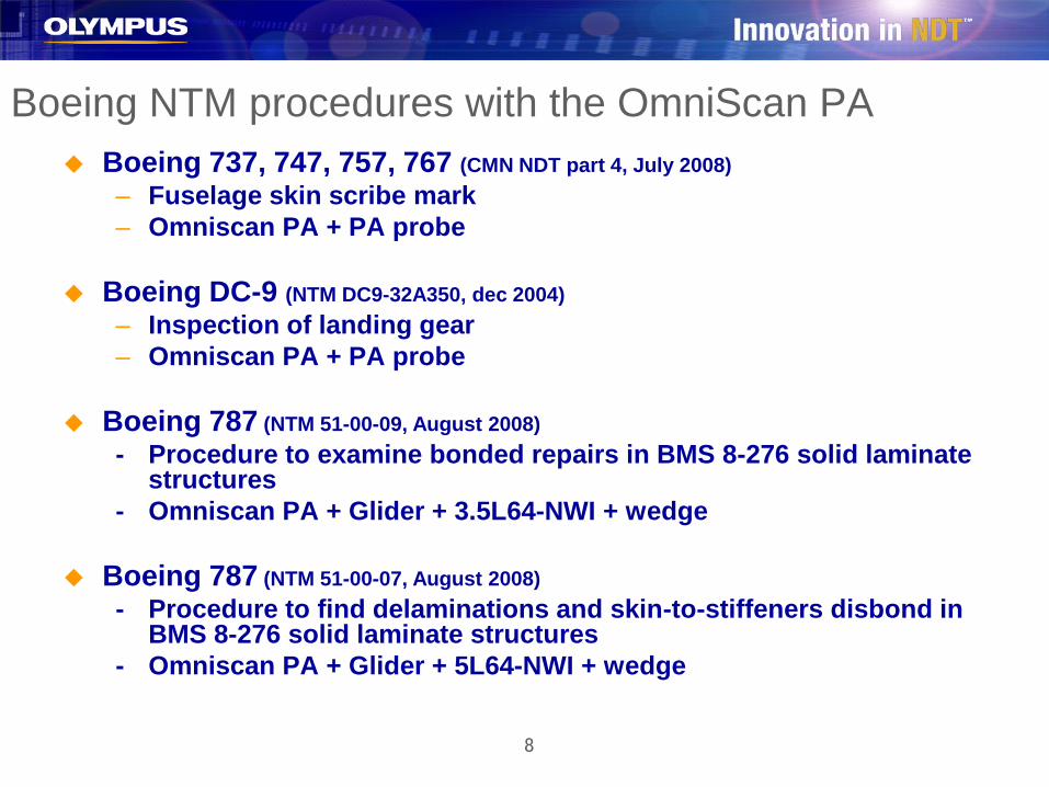
Boeing 737, 747, 757, 767 (CMN NDT part 4, July 2008)– Fuselage skin scribe mark– Omniscan PA + PA probe
Boeing DC-9 (NTM DC9-32A350, dec 2004)– Inspection of landing gear– Omniscan PA + PA probe
Boeing 787 (NTM 51-00-09, August 2008)- Procedure to examine bonded repairs in BMS 8-276 solid laminate
structures- Omniscan PA + Glider + 3.5L64-NWI + wedge
Boeing 787 (NTM 51-00-07, August 2008)- Procedure to find delaminations and skin-to-stiffeners disbond in
BMS 8-276 solid laminate structures- Omniscan PA + Glider + 5L64-NWI + wedge
Boeing NTM procedures with the OmniScan PA
9
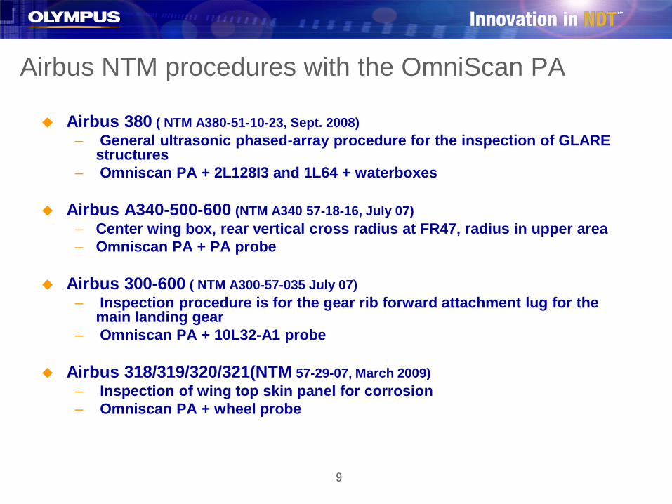
Airbus NTM procedures with the OmniScan PA
Airbus 380 ( NTM A380-51-10-23, Sept. 2008)– General ultrasonic phased-array procedure for the inspection of GLARE
structures– Omniscan PA + 2L128I3 and 1L64 + waterboxes
Airbus A340-500-600 (NTM A340 57-18-16, July 07)– Center wing box, rear vertical cross radius at FR47, radius in upper area– Omniscan PA + PA probe
Airbus 300-600 ( NTM A300-57-035 July 07)– Inspection procedure is for the gear rib forward attachment lug for the
main landing gear– Omniscan PA + 10L32-A1 probe
Airbus 318/319/320/321(NTM 57-29-07, March 2009)– Inspection of wing top skin panel for corrosion– Omniscan PA + wheel probe
10
Scribe mark inspection with ultrasonic phased-array
11
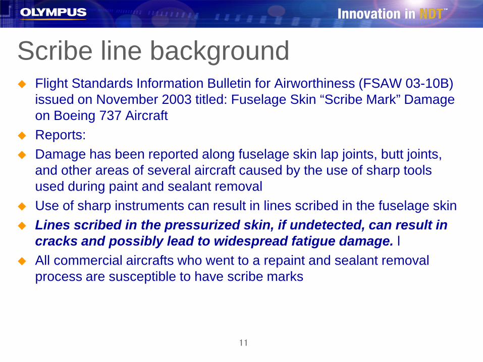
Scribe line background Flight Standards Information Bulletin for Airworthiness (FSAW 03-10B)
issued on November 2003 titled: Fuselage Skin “Scribe Mark” Damage on Boeing 737 Aircraft
Reports: Damage has been reported along fuselage skin lap joints, butt joints,
and other areas of several aircraft caused by the use of sharp tools used during paint and sealant removal
Use of sharp instruments can result in lines scribed in the fuselage skin Lines scribed in the pressurized skin, if undetected, can result in
cracks and possibly lead to widespread fatigue damage. l All commercial aircrafts who went to a repaint and sealant removal
process are susceptible to have scribe marks

12
Boeing 737 configuration
Picture of a scribe mark:
13
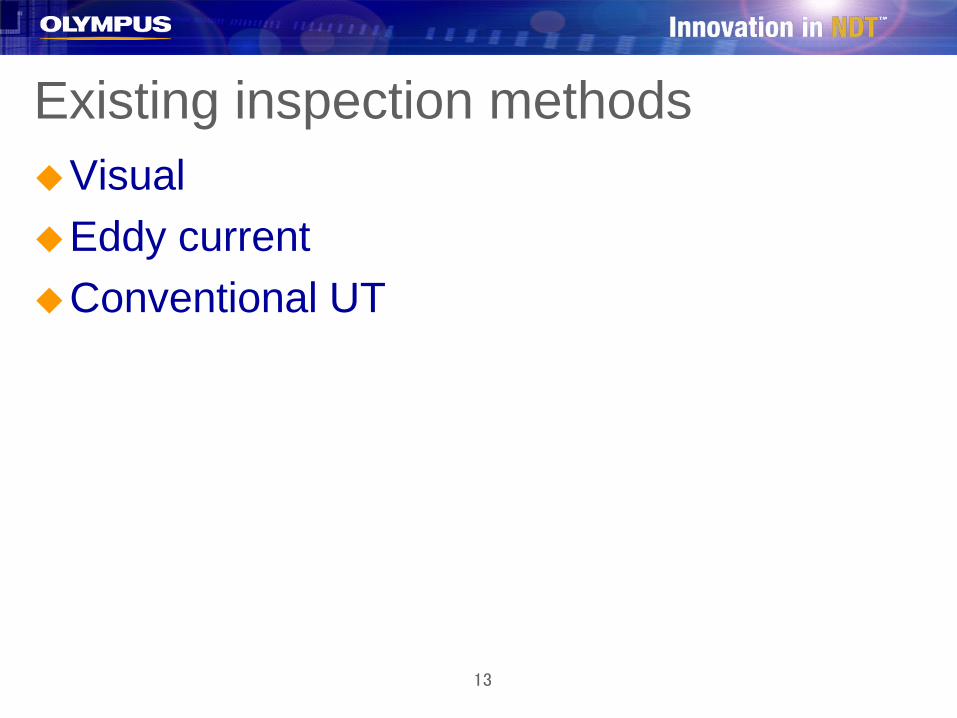
Existing inspection methodsVisualEddy currentConventional UT

14
Advantages of phased-arrayNo paint removal (huge time saving)Sector scan imagingOmniscan PA easy to operateThe smallest configuration of the Omniscan
PA 16:16 is enough (economic)
15
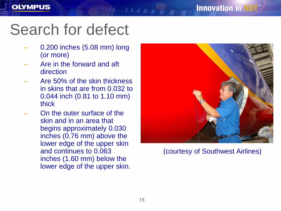
Search for defect– 0.200 inches (5.08 mm) long
(or more)– Are in the forward and aft
direction– Are 50% of the skin thickness
in skins that are from 0.032 to 0.044 inch (0.81 to 1.10 mm) thick
– On the outer surface of the skin and in an area that begins approximately 0.030 inches (0.76 mm) above the lower edge of the upper skin and continues to 0.063 inches (1.60 mm) below the lower edge of the upper skin.
(courtesy of Southwest Airlines)

16
Scribe line inspection
Side of the Probe
Part
angle beam
Wedge
The phased-array probe used is an off-the-shelf probe,
The frequency of the probe is 10 MHz
Mounted on a wedge Sector scan range from 60 to
85 SW No encoder needed
17
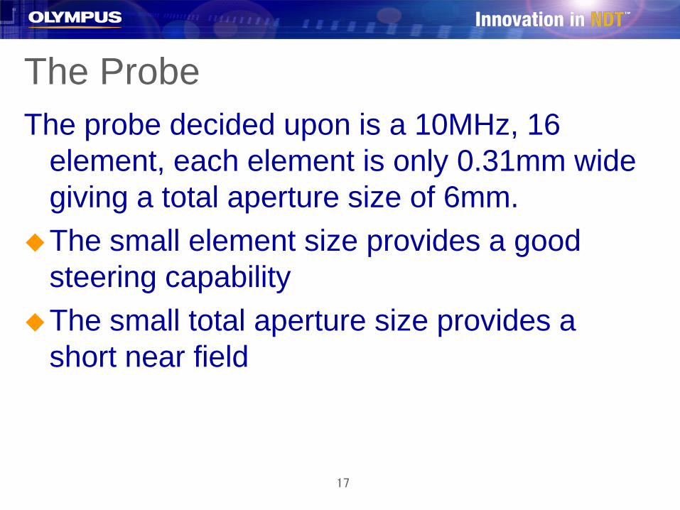
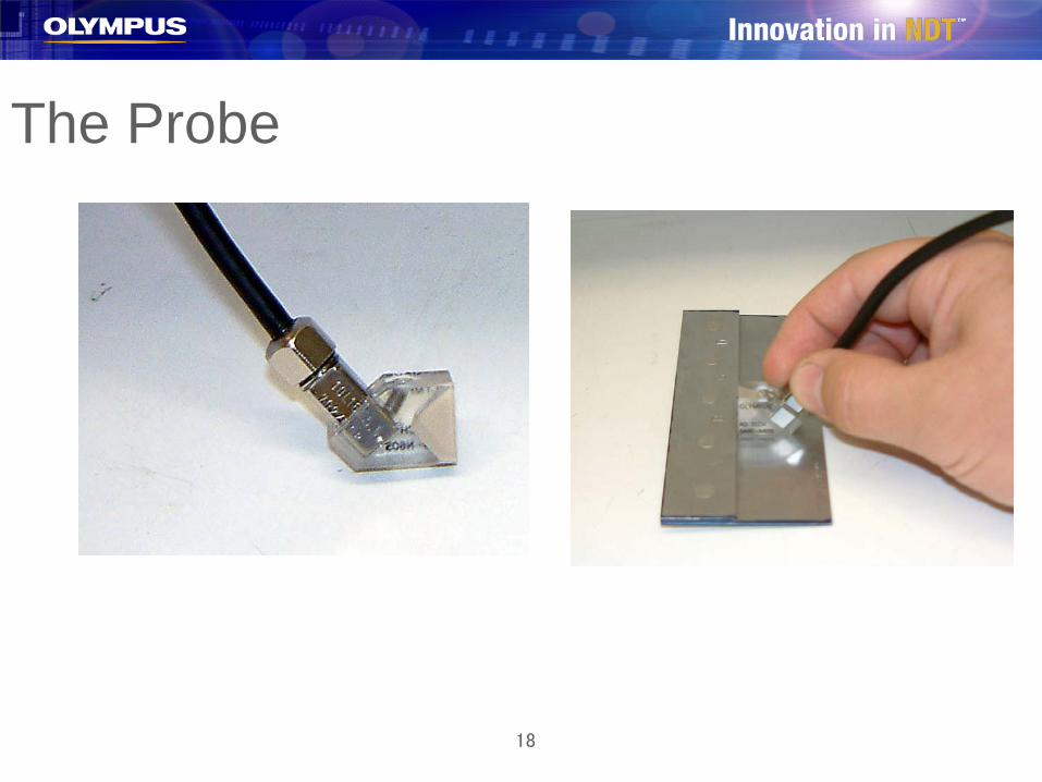
The ProbeThe probe decided upon is a 10MHz, 16
element, each element is only 0.31mm wide giving a total aperture size of 6mm.
The small element size provides a good steering capability
The small total aperture size provides a short near field
18
The Probe

19
Scribe line inspection

20
Scanning technique
Ultrasound
Scanning direction

21
Typical scribe mark indication

22
Omniscan PA imaging
Scribe mark indication Fastener hole indication

23
Conclusions about scribe mark Inspection for scribe mark can be done without paint
removal Extremely fast payback Omniscan PA referenced in the Boeing NTM manuals for
the whole fleet Hundreds of NDT operators trained for this inspection In use by the most of the airliners like Delta, KLM,
Southwest, USAir, Northwest, British Airways, Lufthansa, SAS, …

24
Airbus 320: Inspection of wing top skin panel for corrosion

25
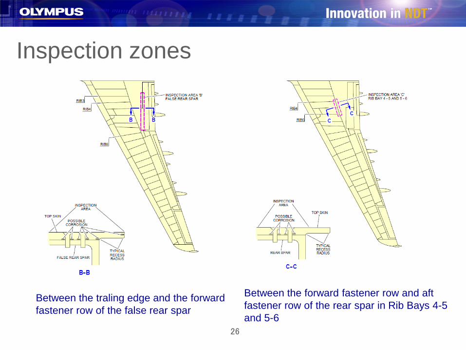
Inspection zones
Rear Spar Inspection Area BetweenRibs 3 to 6 and 9 to 27 and Possible Damage
26
Inspection zones
Between the traling edge and the forward fastener row of the false rear spar
Between the forward fastener row and aft fastener row of the rear spar in Rib Bays 4-5 and 5-6

27
Equipment usedUltrasonic phased-array wheel probe including:50 mm long PA probe5 MHz,64 elements, 0.8 mm pitch
Omniscan PA16:128A, B, Cscan imaging
28
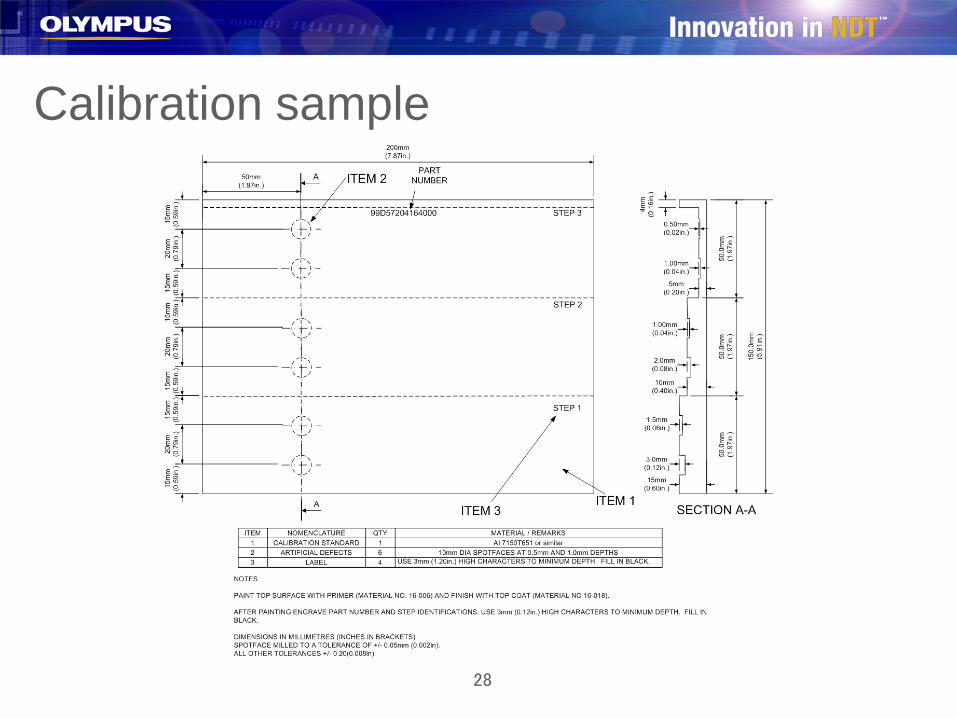
Calibration sample

29
CalibrationEquipment calibration:
-calibrate array for element sensitivity-calibrate array for defect sensitivity using the
reference standard
Instrument display:Ascan,Cscan AmplitudeCscan Time-of-Flight

30
Use configuration
31
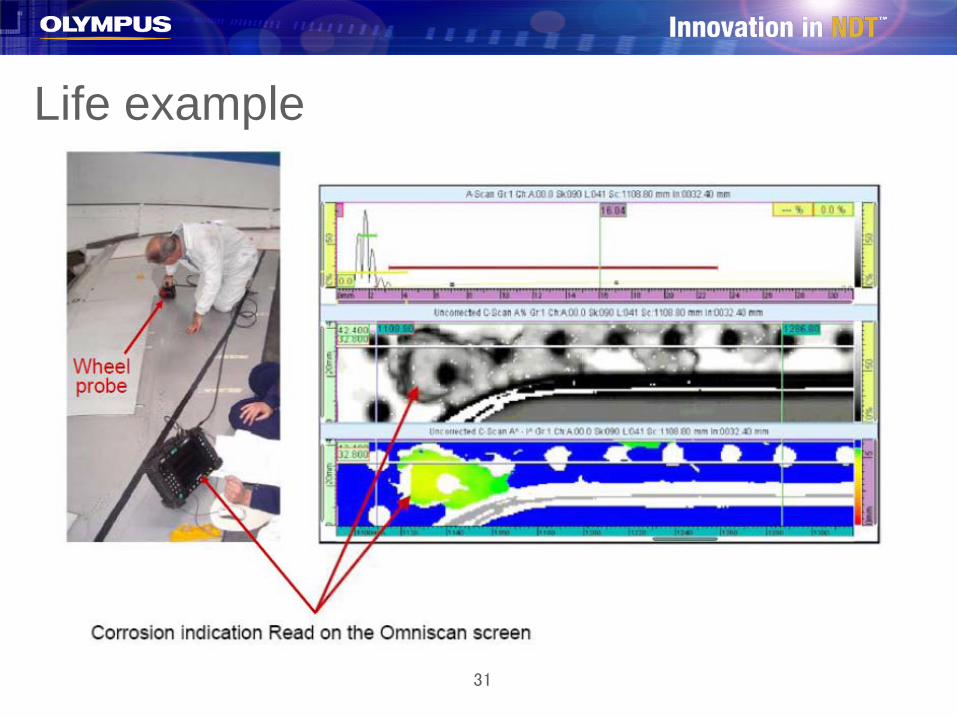
Life example
32
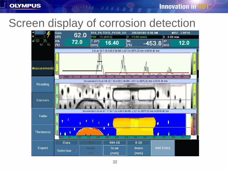
Screen display of corrosion detection

33
Conclusions
•Indications that shows a backwall echo reduction of 4 dbwith a corresponding change of 10% of the material thickness shall be classified as corrosion and reported
•Depth range of corrosion is measured
•Size of the corrosion area is measured
•The scan file is archived for later use
34
Airbus 380 GLARE inspection with ultrasonic phased-array
35
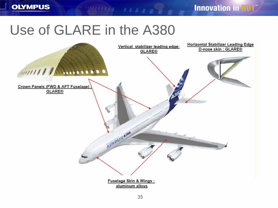
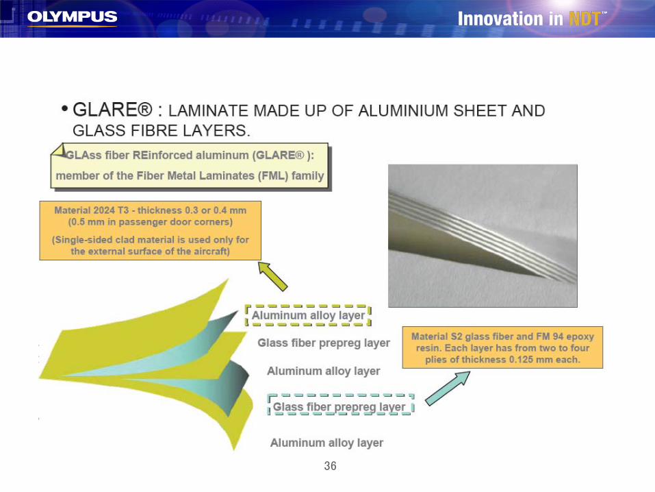
Use of GLARE in the A380
36

37
Typical damage Delaminations and disbounds due to:
– Impact (stone impact, dropped tools, bird strike, ground equipment
– Overheating– Ligthning strikes
The inspection is done after visible detection of damages

38
Possible defect locations
39

40
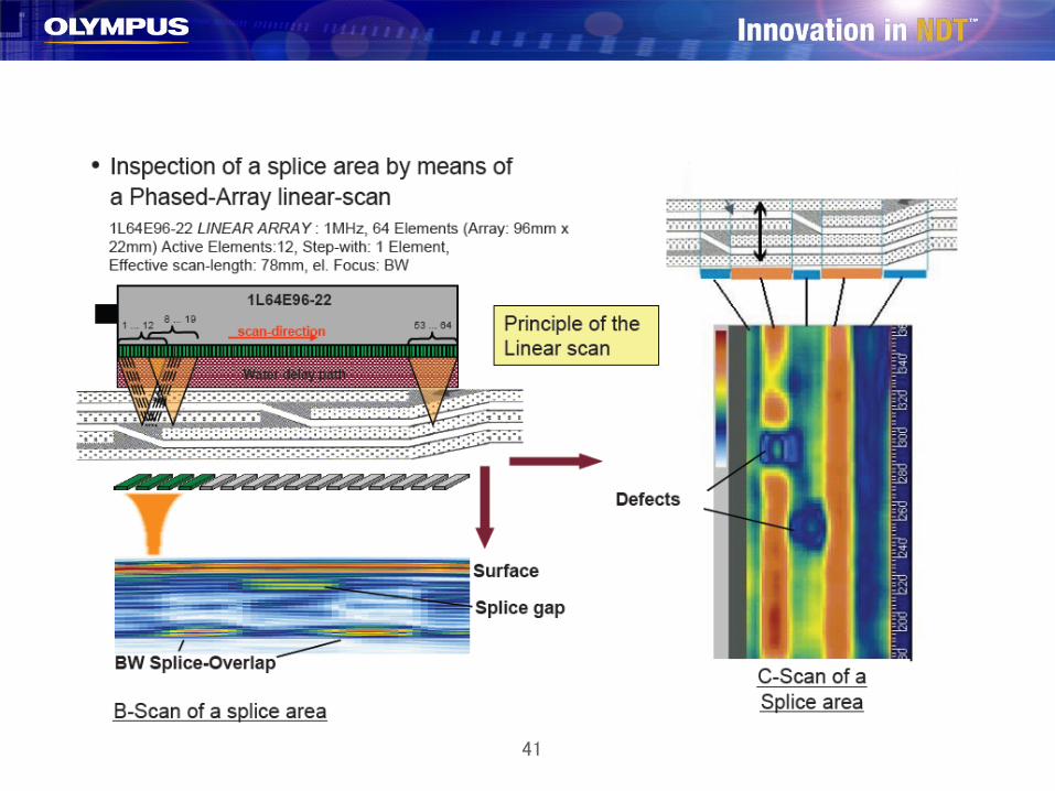
41
42
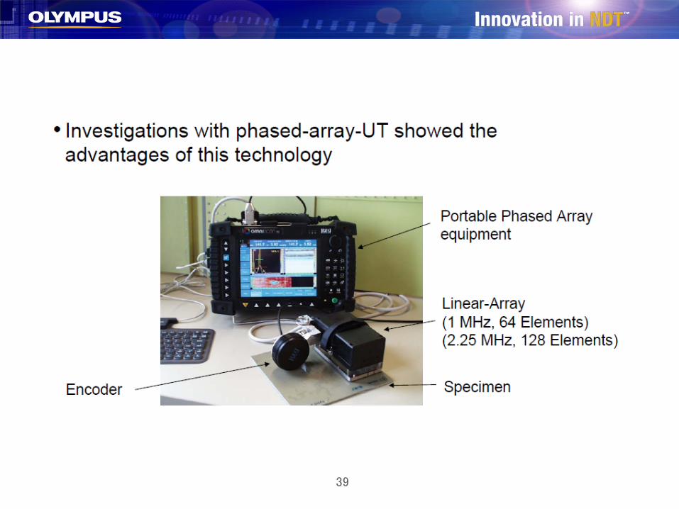
Conclusions about GLARE inspectionUltrasonic phased-array detects
delamination and disbounds in the structures
Cscan imaging improves reliability of the inspection
Use of linear array probe assures full coverage detection

43
Composite inspection during maintenance Efficient data acquisition of large surface areas
requires the following elements.– Acquisition unit allowing for two-axis data acquisition
and C-scans.– UT array probe (PA or paint brush)– Coupling medium
» Wedge with thin film of water– Scanning system
» Manual portable scanner
44
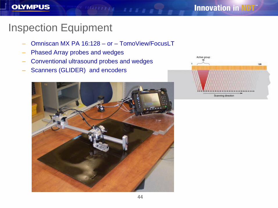
Inspection Equipment– Omniscan MX PA 16:128 – or – TomoView/FocusLT– Phased Array probes and wedges– Conventional ultrasound probes and wedges– Scanners (GLIDER) and encoders
45
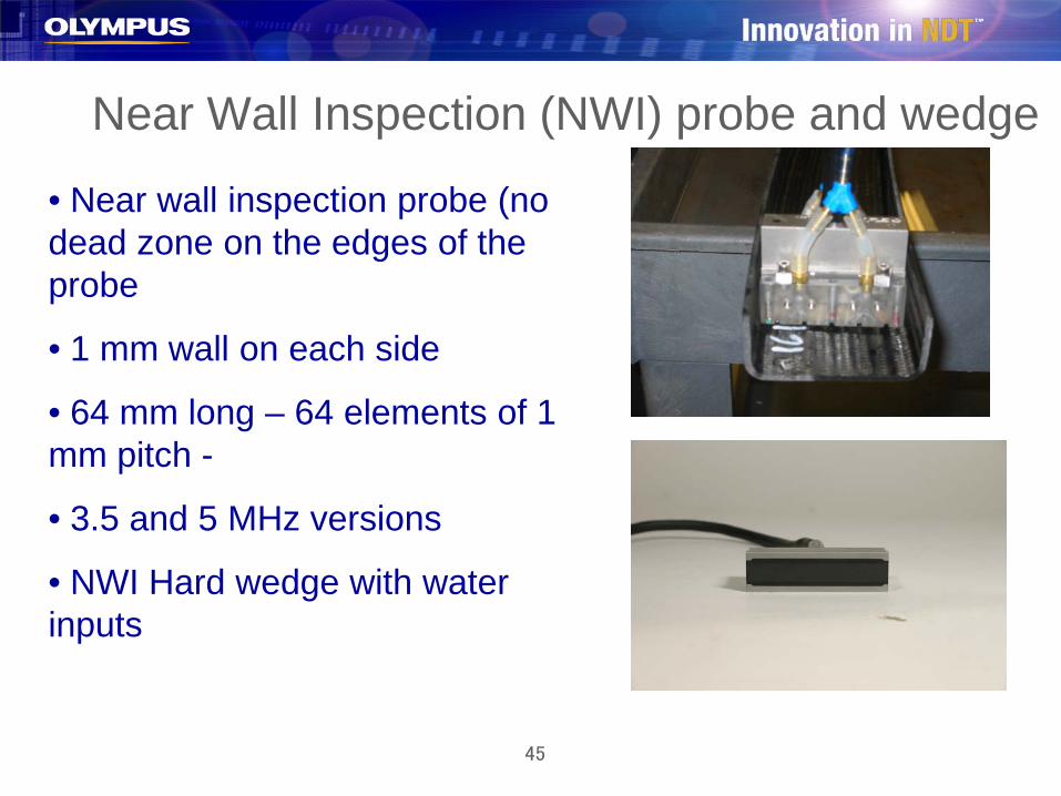
Near Wall Inspection (NWI) probe and wedge
• Near wall inspection probe (no dead zone on the edges of the probe
• 1 mm wall on each side
• 64 mm long – 64 elements of 1 mm pitch -
• 3.5 and 5 MHz versions
• NWI Hard wedge with water inputs

46
The OmniScan® PA, the Glider™ and the 5L64 probe are referenced for C-scan inspections on the Boeing 787(Dreamliner) for both damage detection and bonded repair inspection of composite parts.

47
GLIDER specifications Cscan scanner for area 12 in x 12 in
(300 mm x 300 mm) (other lengths available)
2 axes, 2 encoders, X-Y Encoder: no contact with the part. Encoder resolution: 0.5 mm, 0.020 in Index: variable minimum:0.5 mm, 0.020
in Bonding fixture: 2 manual succion cups
(no need for compressor) Radius: concave and convex 40 cm to 1
m (flat) ; 16 in to 400 in (flat) Can be used with UT PA, conventionnel
UT, Eddy current, ECA, bond tester, etc…
Can accommodate water supply Easy to manipulate and deploy To be used by one operator.

48
Flexible scanner
Version with ventury, it requirescompressor
New version with manualsuccion cups
Travel distance X:940 mm, Y:530 mmEncoder resolution: 0.1 mmMinimum curvature on X: 355 mm
49
Conclusions about ultrasonic phased-array
Deployed in the field for many applicationsReferenced in procedures for aircraft
maintenance AffordableHundreds of aircraft inspectors trained to
use Omniscan PA
50

51
Military applications
52
C130NDI OF OUTER WING LOWER SURFACE
PANEL GENERAL SPANWISE SPLICES
53
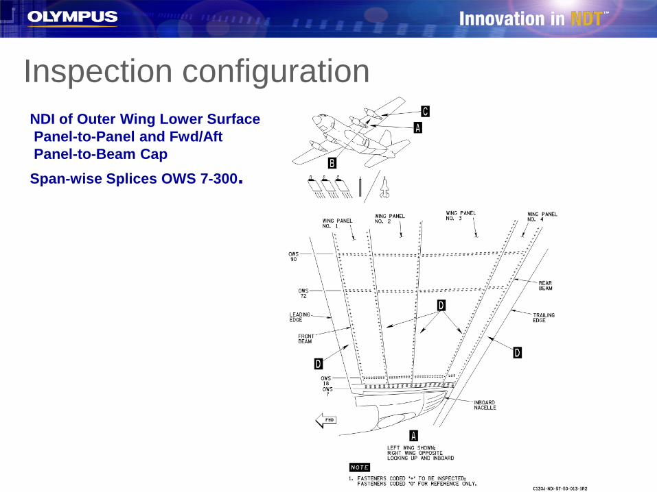
Inspection configurationNDI of Outer Wing Lower SurfacePanel-to-Panel and Fwd/AftPanel-to-Beam CapSpan-wise Splices OWS 7-300.

54
Inspection configuration

55
Scan plan
On the left, sector scanOn the right, linear scan 76 SW across the rivet line
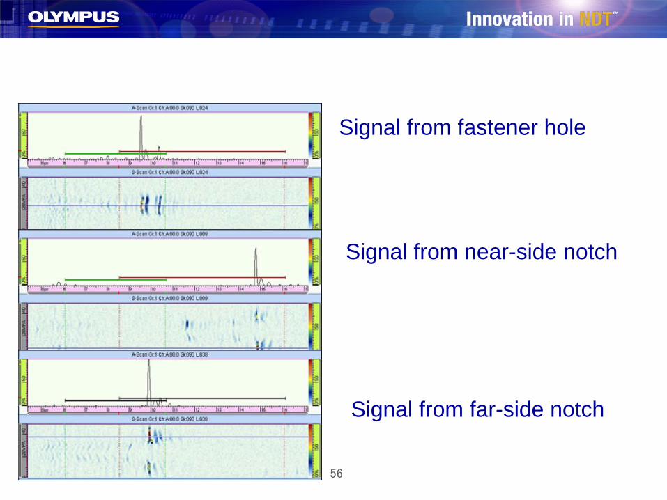
56
Signal from fastener hole
Signal from near-side notch
Signal from far-side notch
57
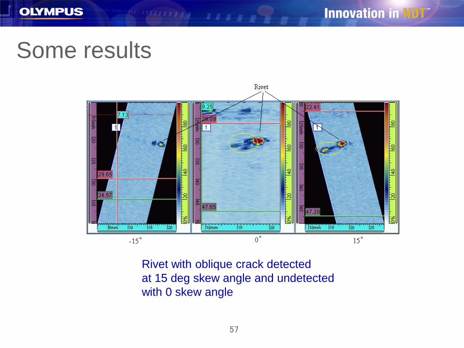
Some results
Rivet with oblique crack detectedat 15 deg skew angle and undetectedwith 0 skew angle

58
AFIS: Automated Fastener-holes Inspection System
– Developed for the USAF under the contract FA8202-05-C-0035
– AFIS detects notches located at the faying surface and the countersink around the fastener holes on aircraft structures without fastener removal
– ROTOSCAN replacement– AFIS in a portable battery operated
automated system – AFIS is adaptation of the famous
Omniscan MX – Portable phased-array unit

59
Inspection requirements 360 degrees around
the fastener holesWithout removing the
fastener Notches located at the
countersink and faying surface
0.05 in round EDM notches
Inspection time less than 1 min
countersinkfaying surface

60
Inspection range
Fastener hole diameter (in)
Min. Skin Thickness(in)
Max. Skin Thickness(in)
3/16 0.18 0.70
1/4 0.18 0.70
5/16 0.45 0.68

61
Calibration standards
EDM notches: 0.05 in (round)Holes with countersink (flat fastener heads)Holes without countersink (raised fastener heads)Removable fasteners (Philips head)

62
Replacing the UT Rotoscan with the AFIS
Rotoscan AFIS
Manual AutomatedConventional UT UT phased-arrayAnalysis with waveform Analysis with Cscan and
Bscan images and waveformNo archieved data Archived dataesProbe angles changed manually Electronic sector scanOne beam for each region Simultaneous sector scan for (countersink, faying surface) each region

63
AFIS configurations Actually, AFIS is
configured for– T-38; flushed fastener
heads– F-5; flushed and raised
fastener heads It can be configured for
other fleets
64
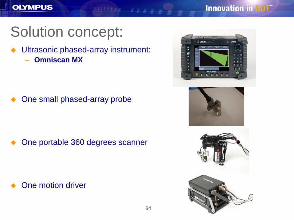
Solution concept: Ultrasonic phased-array instrument:
– Omniscan MX
One small phased-array probe
One portable 360 degrees scanner
One motion driver
65
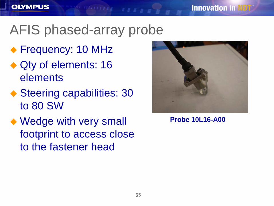
AFIS phased-array probe Frequency: 10 MHzQty of elements: 16
elements Steering capabilities: 30
to 80 SWWedge with very small
footprint to access close to the fastener head
Probe 10L16-A00
66
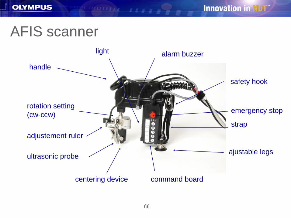
AFIS scanner
ajustable legs
strap
safety hook
handle
command board
emergency stop
centering device
adjustement ruler
ultrasonic probe
rotation setting (cw-ccw)
alarm buzzerlight

67
AFIS scannerWeight: 2 lbs Size: 7 in x 6 in x 3 in
68
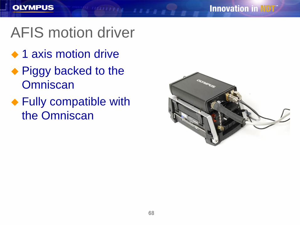
AFIS motion driver 1 axis motion drive Piggy backed to the
Omniscan Fully compatible with
the Omniscan
69
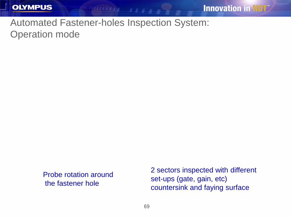
Automated Fastener-holes Inspection System: Operation mode
Probe rotation aroundthe fastener hole
2 sectors inspected with different set-ups (gate, gain, etc)countersink and faying surface
70
Automated Fastener-holes Inspection System: Operation mode
Sequence:
CouplingScanner positioningHomingInspectionFreezeAnalysis
71
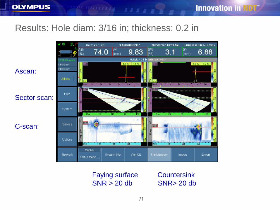
Results: Hole diam: 3/16 in; thickness: 0.2 in
Faying surface CountersinkSNR > 20 db SNR> 20 db
Ascan:
Sector scan:
C-scan:
72
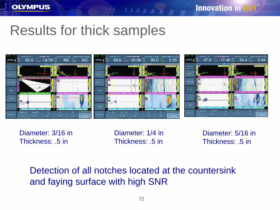
Results for thick samples
Diameter: 3/16 inThickness: .5 in
Diameter: 1/4 inThickness: .5 in
Diameter: 5/16 inThickness: .5 in
Detection of all notches located at the countersinkand faying surface with high SNR
73
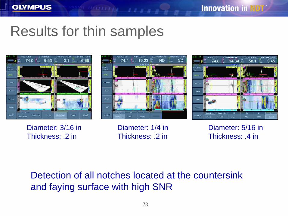
Results for thin samples
Diameter: 3/16 inThickness: .2 in
Diameter: 1/4 inThickness: .2 in
Diameter: 5/16 inThickness: .4 in
Detection of all notches located at the countersinkand faying surface with high SNR

74
Conclusion AFIS detects all notches within the desired range of
thickness and diameter Detection with very high SNR Inspection done in less than 30 sec for each fastener holes Less operator dependant (because automated) Reliable (image and pre-defined setting reduce risk of
error) Easy to use Can be configured for other fleets than T-38 and F-5


76