ultrasonic sensors 940 series compact 18 mm diameter digital
TRANSCRIPT
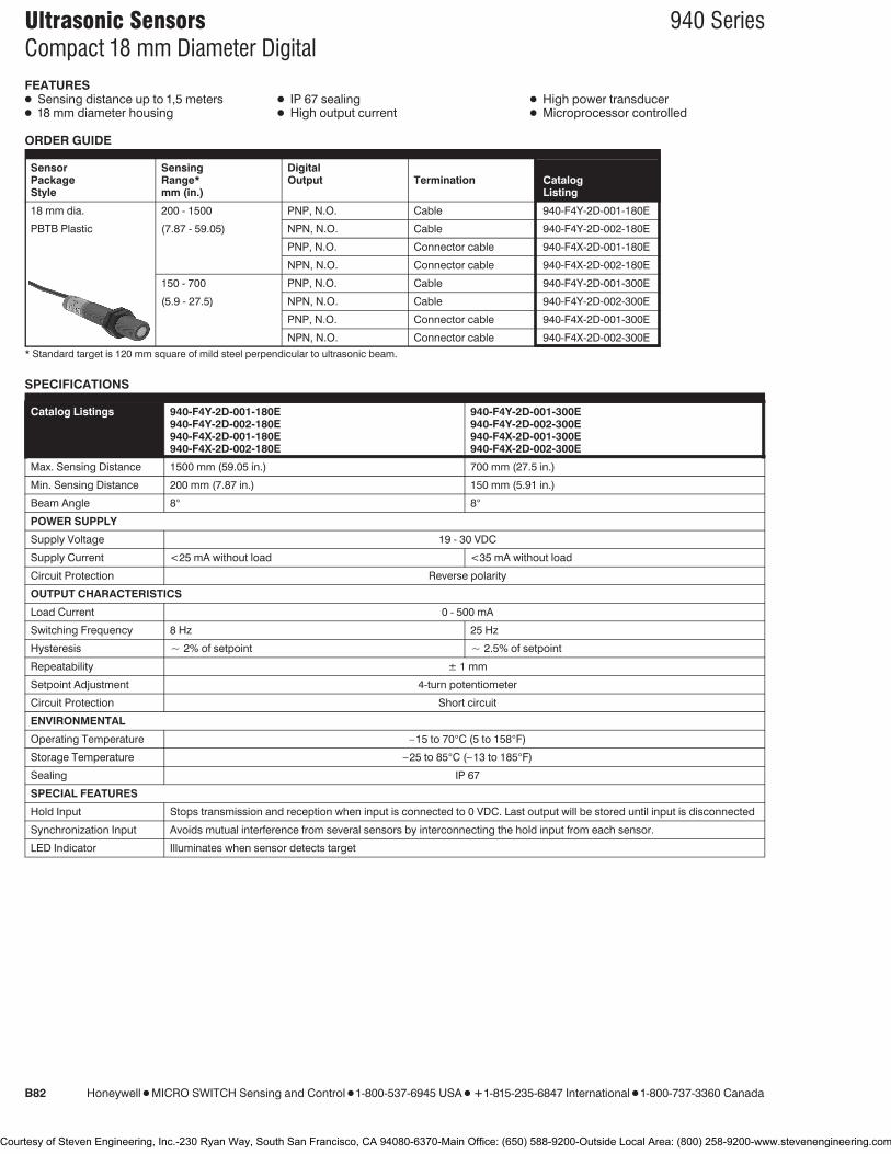
Ultrasonic Sensors 940 SeriesCompact 18 mm Diameter Digital
B82 Honeywell 1 MICRO SWITCH Sensing and Control 1 1-800-537-6945 USA 1 F1-815-235-6847 International 1 1-800-737-3360 Canada
FEATURES1 Sensing distance up to 1,5 meters1 18 mm diameter housing
1 IP 67 sealing1 High output current
1 High power transducer1 Microprocessor controlled
ORDER GUIDE
Sensor Sensing DigitalPackage Range* Output Termination CatalogStyle mm (in.) Listing
18 mm dia. 200 - 1500 PNP, N.O. Cable 940-F4Y-2D-001-180E
PBTB Plastic (7.87 - 59.05) NPN, N.O. Cable 940-F4Y-2D-002-180E
PNP, N.O. Connector cable 940-F4X-2D-001-180E
NPN, N.O. Connector cable 940-F4X-2D-002-180E
150 - 700 PNP, N.O. Cable 940-F4Y-2D-001-300E
(5.9 - 27.5) NPN, N.O. Cable 940-F4Y-2D-002-300E
PNP, N.O. Connector cable 940-F4X-2D-001-300E
NPN, N.O. Connector cable 940-F4X-2D-002-300E* Standard target is 120 mm square of mild steel perpendicular to ultrasonic beam.
SPECIFICATIONS
Catalog Listings 940-F4Y-2D-001-180E 940-F4Y-2D-001-300E940-F4Y-2D-002-180E 940-F4Y-2D-002-300E940-F4X-2D-001-180E 940-F4X-2D-001-300E940-F4X-2D-002-180E 940-F4X-2D-002-300E
Max. Sensing Distance 1500 mm (59.05 in.) 700 mm (27.5 in.)
Min. Sensing Distance 200 mm (7.87 in.) 150 mm (5.91 in.)
Beam Angle 8° 8°
POWER SUPPLY
Supply Voltage 19 - 30 VDC
Supply Current <25 mA without load <35 mA without load
Circuit Protection Reverse polarity
OUTPUT CHARACTERISTICS
Load Current 0 - 500 mA
Switching Frequency 8 Hz 25 Hz
Hysteresis ` 2% of setpoint ` 2.5% of setpoint
Repeatability ± 1 mm
Setpoint Adjustment 4-turn potentiometer
Circuit Protection Short circuit
ENVIRONMENTAL
Operating Temperature –15 to 70°C (5 to 158°F)
Storage Temperature –25 to 85°C (–13 to 185°F)
Sealing IP 67
SPECIAL FEATURES
Hold Input Stops transmission and reception when input is connected to 0 VDC. Last output will be stored until input is disconnected
Synchronization Input Avoids mutual interference from several sensors by interconnecting the hold input from each sensor.
LED Indicator Illuminates when sensor detects target
Courtesy of Steven Engineering, Inc.-230 Ryan Way, South San Francisco, CA 94080-6370-Main Office: (650) 588-9200-Outside Local Area: (800) 258-9200-www.stevenengineering.com

Ultrasonic Sensors 940 SeriesCompact 18 mm Diameter Digital
Honeywell 1 MICRO SWITCH Sensing and Control 1 1-800-537-6945 USA 1 F1-815-235-6847 International 1 1-800-737-3360 Canada B83
WIRING DIAGRAM
*Normal operation with no connection
MOUNTING DIMENSIONS (For reference only)940-F4X/Y-20-001/2-180E
940-F4X/Y-20-001/2-300E Versions only
940-F4X/Y-2D-001/2-300E
4-pin DC Micro(M12 x 1)Pin Color1 BRN2 PINK3 BLU4 BLK
ACCESSORIES
Catalog Listing Feature
Mounting clamp 43178389-018 Allows mounting to a flat surface
Beam deflector 43192871-003 Allows right angle mounting (Approx. dim. 50 x 170 mm)
Focusing beam deflector 43192871-004 Reduces beam angle by approximately 1/2 (Approx. dim.35 x 52 mm)
Straight connector w/o cable 66195044-001 Connector has screw terminals for wiring connection
Right angle connector w/o cable 66195045-001 Connector has screw terminals for wiring connection
24 VDC Power supply, Relay output, 110 VAC input FF-MADB24RB See page B102 for more information
24 VDC POwer supply, On/Off delay, 110 VAC input FF-MADC24RB See page B102 for more information
Pro
ximity
Courtesy of Steven Engineering, Inc.-230 Ryan Way, South San Francisco, CA 94080-6370-Main Office: (650) 588-9200-Outside Local Area: (800) 258-9200-www.stevenengineering.com

Ultrasonic Sensors 940 Series30 mm Diameter Analog
B84 Honeywell 1 MICRO SWITCH Sensing and Control 1 1-800-537-6945 USA 1 F1-815-235-6847 International 1 1-800-737-3360 Canada
FEATURES1 Measuring range up to 2000 mm (78.74
in.)1 High repeatability
ORDER GUIDE
Sensor SensingPackage Range* Analog Termi- CatalogStyle mm (in.) Output nation Listing
30 mm dia. 300 - 2000 1.5 - 10 V Cable 940-A4Y-AD-1C0-130EStainless Steel (11.81 - 78.74)
150 - 1200 1.25 - 10 V Cable 940-A4Y-AD-1C0
(5.90 - 47.24) Connector 940-A4V-AD-1C0
* Standard target is 120 mm square of mild steel perpendicular to ultrasonic beam.
SPECIFICATIONS
Catalog Listings 940-A4Y-AD-1C0940-A4Y-AD-1C0-130E 940-A4V-AD-1C0
Max. Range Max. Rate Max. Range Max. Rate
Max. Sensing Distance 2000 mm (78.74 in.) 1000 mm (39.37 in.) 1200 mm (47.2 in.) 600 mm (23.6 in.)
Min. Sensing Distance 300 mm (11.8 in.) 150 mm (5.91 in.)
Beam Angle 8° 10°
POWER SUPPLY
Supply Voltage 19 - 30 VDC
Supply Current <20 mA without load
Circuit Protection Reverse polarity
OUTPUT CHARACTERISTICS
Load Current 10 mA max.
Switching Frequency 6 Hz 11 Hz
Repeatability ±2 mm ±1 mm
Linearity <0.2%
Output Adjustment 4 Turn Potentiometer
Output Mode Max. Range or Max. Rate selected by wiring terminal connection
Circuit Protection Short Circuit
ENVIRONMENTAL
Operating Temperature 0 to 50°C (32 to 122°F)
Storage Temperature 0 to 70°C (32 to 158°F)
Sealing IP 65
SPECIAL FEATURES
Hold Input Stops transmission and reception of sensor when input is connected to 0 VDC. Analog output would be zero.
Synchronization Input Avoids mutual interference from several ultrasonic sensors (external synchronization unit required; see Accessories)
LED Indicator Illuminates when sensor detects a target
Courtesy of Steven Engineering, Inc.-230 Ryan Way, South San Francisco, CA 94080-6370-Main Office: (650) 588-9200-Outside Local Area: (800) 258-9200-www.stevenengineering.com

Ultrasonic Sensors 940 Series30 mm Diameter Analog
Honeywell 1 MICRO SWITCH Sensing and Control 1 1-800-537-6945 USA 1 F1-815-235-6847 International 1 1-800-737-3360 Canada B85
WIRING DIAGRAM
*Normal operation with connection +19-30 VDC
CONNECTOR VERSIONONLY
Pin Color1 BRN2 WHT3 BLU4 BLK5 GRAY
MOUNTING DIMENSIONS (For reference only)940-A4V-AD-1C0
940-A4Y-AD-1C0-130E940-A4Y-AD-1C0
ACCESSORIES
Catalog Listing Feature
Mounting clamp, 30 mm sensor 43178389-030 Allows mounting to a flat surface
Beam deflector 43192871-001 Allows right angle mounting (Approx. dim. 50 x 170 mm)
Focusing beam deflector 43192871-002 Reduces beam angle by approximately 1/2
Compact deflector 66195116-001 Allows right angle mounting (Approx. dim. 35 x 52 mm)
2 meter cable, Straight connector RKT5-612/2M Used for wiring to connector version
5 meter cable, Straight connector RKT5-612/5M Used for wiring to connector version
2 meter cable, Right angle connector RKWT5-612/2M Used for wiring to connector version
5 meter cable, Right angle connector RKWT5-612/5M Used for wiring to connector version
Synchronization unit 55000001 Controls up to 100 sensors
Pro
ximity
Courtesy of Steven Engineering, Inc.-230 Ryan Way, South San Francisco, CA 94080-6370-Main Office: (650) 588-9200-Outside Local Area: (800) 258-9200-www.stevenengineering.com
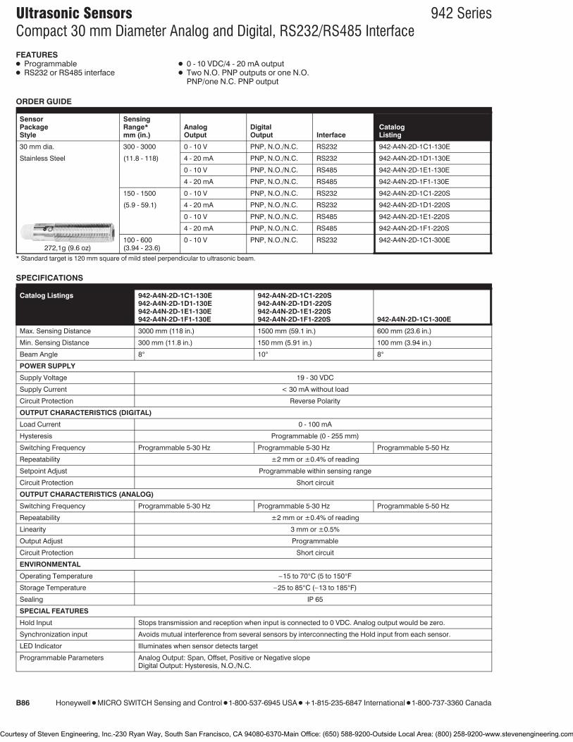
Ultrasonic Sensors 942 SeriesCompact 30 mm Diameter Analog and Digital, RS232/RS485 Interface
B86 Honeywell 1 MICRO SWITCH Sensing and Control 1 1-800-537-6945 USA 1 F1-815-235-6847 International 1 1-800-737-3360 Canada
FEATURES1 Programmable1 RS232 or RS485 interface
1 0 - 10 VDC/4 - 20 mA output1 Two N.O. PNP outputs or one N.O.
PNP/one N.C. PNP output
ORDER GUIDE
Sensor SensingPackage Range* Analog Digital CatalogStyle mm (in.) Output Output Interface Listing
30 mm dia. 300 - 3000 0 - 10 V PNP, N.O./N.C. RS232 942-A4N-2D-1C1-130E
Stainless Steel (11.8 - 118) 4 - 20 mA PNP, N.O./N.C. RS232 942-A4N-2D-1D1-130E
0 - 10 V PNP, N.O./N.C. RS485 942-A4N-2D-1E1-130E
4 - 20 mA PNP, N.O./N.C. RS485 942-A4N-2D-1F1-130E
150 - 1500 0 - 10 V PNP, N.O./N.C. RS232 942-A4N-2D-1C1-220S
(5.9 - 59.1) 4 - 20 mA PNP, N.O./N.C. RS232 942-A4N-2D-1D1-220S
0 - 10 V PNP, N.O./N.C. RS485 942-A4N-2D-1E1-220S
4 - 20 mA PNP, N.O./N.C. RS485 942-A4N-2D-1F1-220S
100 - 600 0 - 10 V PNP, N.O./N.C. RS232 942-A4N-2D-1C1-300E(3.94 - 23.6)272,1g (9.6 oz)
* Standard target is 120 mm square of mild steel perpendicular to ultrasonic beam.
SPECIFICATIONS
Catalog Listings 942-A4N-2D-1C1-130E 942-A4N-2D-1C1-220S942-A4N-2D-1D1-130E 942-A4N-2D-1D1-220S942-A4N-2D-1E1-130E 942-A4N-2D-1E1-220S942-A4N-2D-1F1-130E 942-A4N-2D-1F1-220S 942-A4N-2D-1C1-300E
Max. Sensing Distance 3000 mm (118 in.) 1500 mm (59.1 in.) 600 mm (23.6 in.)
Min. Sensing Distance 300 mm (11.8 in.) 150 mm (5.91 in.) 100 mm (3.94 in.)
Beam Angle 8° 10° 8°
POWER SUPPLY
Supply Voltage 19 - 30 VDC
Supply Current < 30 mA without load
Circuit Protection Reverse Polarity
OUTPUT CHARACTERISTICS (DIGITAL)
Load Current 0 - 100 mA
Hysteresis Programmable (0 - 255 mm)
Switching Frequency Programmable 5-30 Hz Programmable 5-30 Hz Programmable 5-50 Hz
Repeatability ±2 mm or ±0.4% of reading
Setpoint Adjust Programmable within sensing range
Circuit Protection Short circuit
OUTPUT CHARACTERISTICS (ANALOG)
Switching Frequency Programmable 5-30 Hz Programmable 5-30 Hz Programmable 5-50 Hz
Repeatability ±2 mm or ±0.4% of reading
Linearity 3 mm or ±0.5%
Output Adjust Programmable
Circuit Protection Short circuit
ENVIRONMENTAL
Operating Temperature –15 to 70°C (5 to 150°F
Storage Temperature –25 to 85°C (–13 to 185°F)
Sealing IP 65
SPECIAL FEATURES
Hold Input Stops transmission and reception when input is connected to 0 VDC. Analog output would be zero.
Synchronization input Avoids mutual interference from several sensors by interconnecting the Hold input from each sensor.
LED Indicator Illuminates when sensor detects target
Programmable Parameters Analog Output: Span, Offset, Positive or Negative slopeDigital Output: Hysteresis, N.O./N.C.
Courtesy of Steven Engineering, Inc.-230 Ryan Way, South San Francisco, CA 94080-6370-Main Office: (650) 588-9200-Outside Local Area: (800) 258-9200-www.stevenengineering.com

Ultrasonic Sensors 942 SeriesCompact 30 mm Diameter Analog and Digital, RS232/RS485 Interface
Honeywell 1 MICRO SWITCH Sensing and Control 1 1-800-537-6945 USA 1 F1-815-235-6847 International 1 1-800-737-3360 Canada B87
WIRING DIAGRAM
*Normal operation with no connection
MOUNTING DIMENSIONS (For reference only)
ACCESSORIES
Catalog Listing Features
Mounting clamp 43178389-030 Allows mounting to flat surface
Beam deflector 43192871-001 Allows right angle mounting (approx. dim. 50 x 170 mm)
Focusing beam deflector 43192871-002 Reduces beam angle by approximately 50%
Compact deflector 66195116-001 Allows right angle mounting (approx. dim. 35 x 52 mm)
Programming adapter 55000005-002 Allows sensor programming via RS232 interface
RS232/RS485 converter 55000003-001 Converts RS232 interface to RS485 interface
24 VDC Power supply, relay output, 110 VAC input FF-MADB24RB See page B102 more information
24 VDC Power supply, On/Off delay, 110 VAC input FF-MADC24RB See page B102 more information
Software package (disk, manual, cable + 1 sub min D9connector) 55195101-101 Allows programming of sensor
Software package (disk, manual, cable + 2 sub min D9connectors) 55195101-102 Allows programming of sensor
Straight connector 66195126-001 Used for wiring to connector
2 meter cable with straight connector 55195126-001 Used for wiring to connector
Pro
ximity
Courtesy of Steven Engineering, Inc.-230 Ryan Way, South San Francisco, CA 94080-6370-Main Office: (650) 588-9200-Outside Local Area: (800) 258-9200-www.stevenengineering.com

Ultrasonic Sensors 942 Series2-Piece 30 mm DiameterPrecision Switching, Analog, Digital BCD, Hexadecimal Outputs
B88 Honeywell 1 MICRO SWITCH Sensing and Control 1 1-800-537-6945 USA 1 F1-815-235-6847 International 1 1-800-737-3360 Canada
FEATURES1 Background suppression1 Sensor sealed to IP 651 Amplifier sealed to IP 541 DIN rail mounting
1 Compensated over 0 to 50°C(32 to 120°F)
1 Amplifier provides analog, digitalswitching, BCD or hexadecimal outputs
ORDER GUIDE
Sensor Sensing MultiplexPackage Range* Digital Digital Analog CatalogStyle mm (in.) Output** Output Output Listing***
30 mm (1.18 in.) 150 - 1500 Two PNP BCD/HEX 0 - 10 VDC 942-M3A-2D-1G1-220SStainless steel sensor head (5.9 - 59.0) N.O. or N.C. 4 - 20 mA
*Standard target: 120 mm thicksquare of mild steel perpendicular toultrasonic beam.**N.O./N.C. output selectable***Includes stainless steel sensorhead, cable, straight connector andamplifier.
272g (9.6 oz)
SPECIFICATIONSMax. Sensing Distance 1500 mm (59.1 in.)
Min. Sensing Distance 150 mm (5.91 in.)
Beam Angle 10°/5°POWER SUPPLY
Supply Voltage 19-30 VDC
Supply Current <130 mA without load
Circuit Protection Reverse polarity
OUTPUT CHARACTERISTICS (DIGITAL)
Load Current 0-100 mA
Hysteresis ±1% of setpoint
Switching Frequency 8 Hz
Repeatability ±1 mm or 0.2% of reading
Setpoint Adjustment Digital switches
Output Adjustment Beam angle 10° w/max. sensitivity or beam angle 5° w/min. sensitivity
Circuit Protection Short circuit
OUTPUT CHRACTERISTICS (MULTIPLEX DIGITAL)
Resolution 1 mm
Information Output Bit Parallel/Word Serial
Setpoint Adjustment Beam angle 10° w/max. sensitivity or beam angle 5° w/min. sensitivity
OUTPUT CHARACTERISTICS (ANALOG)
Switching Frequency 8 Hz
Repeatability ±1 mm or 0.2% of reading
Linearity ±2 mm or 0.3%
Output Range Adjustment Digital switches
Output Adjustment Beam angle 10° w/max. sensitivity or beam angle 5° w/min. sensitivity
Min. Load Resistance (VDC) 1000 Ohms (0-10 VDC output)
Max. Load Resistance (mA) 250 Ohms (4-20 mA output)
Slope of Output Positive or Negative via switch
ENVIRONMENTAL
Operating Temperature Sensor head: 0 to 70°C (32 to 158°F)/Amplifier: 0 to 50°C (32 to 122°F)
Storage Temperature Sensor head/Amplifier: –25 to 85°C (–13 to 185°F)
Sealing Sensor Head: IP 65/Amplifier: IP 54
SPECIAL FEATURES
LED Indicators RED - Under Range/ RED - Over Range: illumination dependent on analog range chosen and targetposition with respect to sensorYELLOW - Setpoint: illuminates when target reaches setpoint 1 or setpoint 2
Hold Input Stops transmission and reception when input is connected to 0 VDC. Last output stored until input is disconnected
Synchronization Input Avoids mutual interference from several sensors by interconnecting the hold input from each sensor
Courtesy of Steven Engineering, Inc.-230 Ryan Way, South San Francisco, CA 94080-6370-Main Office: (650) 588-9200-Outside Local Area: (800) 258-9200-www.stevenengineering.com

Ultrasonic Sensors 942 Series2-Piece 30 mm DiameterPrecision Switching, Analog, Digital BCD, Hexadecimal Outputs
Honeywell 1 MICRO SWITCH Sensing and Control 1 1-800-537-6945 USA 1 F1-815-235-6847 International 1 1-800-737-3360 Canada B89
WIRING DIAGRAM MOUNTING DIMENSIONS (For reference only)PWS External supply terminals1 19-30 V 19-30 V supply2 GND 0 V lineSensor head Sensor head terminals3 19-30 V +Vs supply voltage4 GND 0 V line5 STA Signal transmit
command6 STO Stop signal, echo
received7 SEN Receive sensitivity8 TEM Temperature sensorRM CO Transmit control9 GND 0 V line10 HLD Transmit inhibit,
synchronizeOutputs Switching outputs11 GND 0 V line12 ORA No echo, out of range13 URA Under range, target too
close14 SP1 Switching output 115 SP2 Switching output 2Analog out Analog outputs16 V V out, 0-10 V17 GND 0 V line18 I Current out, 4-20 mADigital out Multiplexed digital
outputs23 103 1000 decade strobe24 102 100 decade strobe25 101 10 decade strobe26 100 1 decade strobe27 23 8 BCD/HEX28 22 4 BCD/HEX29 21 2 BCD/HEX30 20 1 BCD/HEX
ACCESSORIES
Catalog Listing Features
Mounting clamp 43178389-030 Allows mounting to flat surface
Beam deflector 43192871-001 Allows right angle mounting (approx. dim. 50 x 170 mm)
Focusing beam deflector 43192871-002 Reduces beam angle by approximately 50%
Compact deflector 66195116-001 Allows right angle mounting (approx. dim. 35 x 52 mm)
REPLACEMENT LISTINGSSensor Head 942A4M-2D-K220S
Amplifier 942-M0A-2D-1G1-220S
Straight Connector (cable not included) 66195074-001
942 SERIES ULTRASONIC CROSS REFERENCEObsolete Listing Replacement Listing Comments
942-M88 942-M96 Sensor head, includes942-M88-LF connector
942-M3A-2D-1G1 942-M0A-2D-1G1-220S Amplifier
Pro
ximity
Courtesy of Steven Engineering, Inc.-230 Ryan Way, South San Francisco, CA 94080-6370-Main Office: (650) 588-9200-Outside Local Area: (800) 258-9200-www.stevenengineering.com

Temperature Sensors HRTS SeriesPlatinum RTDs
Honeywell 1 MICRO SWITCH Sensing and Control 1 1-800-537-6945 USA 1 F1-815-235-6847 International 1 1-800-737-3360 Canada 93
FEATURES1 Resistance interchangeable1 Accurate1 Linear1 Fast1 Laser trimmed1 Bolt, cement-on or strap-on models
TYPICAL APPLICATIONS1 HVAC – room, duct and refrigerant
equipment1 OEM assemblies1 Electronic assemblies –
semiconductor protection,temperature compensation
1 Process control – temperatureregulation
The HRTS is designed to measure sur-face temperatures from −200° to +480°C(−320° to +900°F) in printed circuit, tem-perature probe, or other applications.
HRTS surface temperature sensors arefully assembled elements, ready to use,without the need for fragile splices to ex-tension leads.
A thin layer of platinum is deposited on analumina substrate and laser trimmed to aresistance interchangeability of ±0.2%with ±0.5°C accuracy or ±0.1% with±0.3°C accuracy. The sensor chip is thenglassed, wired and potted or ceramicfired to result in a cylindrical aluminapackage with either Teflon or fiber glassinsulated lead wires.
ORDER GUIDE
HRTS-5760-B Miniature, ceramic body, 28 ga TFE Teflon insulated leads (2-wire only)
HRTS-61 Bolt-on, nickel plated copper alloy body, 24 ga fiberglass insulated leads,SST braid, TFE overwrap, spiral armor
-T 100V, 0.00385 V/V/°C, 3-wire leads, DIN specification
-U 1000V, 0.00375 V/V/°C, 2-wire leads
-0 ±0.2% Resistance Trim (Standard)
-1 ±0.1% Resistance Trim (Optional)
-12 Standard length, HRTS-5760-B
-24 Standard length, HRTS-61
MOUNTING DIMENSIONS (for reference only)
HRTS-5760-B
HRTS-61
Fig. 1: Wheatstone Bridge 2-WireInterface
Fig. 2: Linear Output Voltage
Fig. 3: Adjustable Point (Comparator)Interface
Temp
erature
Courtesy of Steven Engineering, Inc.-230 Ryan Way, South San Francisco, CA 94080-6370-Main Office: (650) 588-9200-Outside Local Area: (800) 258-9200-www.stevenengineering.com

Temperature Sensors HRTS SeriesPlatinum RTDs
94 Honeywell 1 MICRO SWITCH Sensing and Control 1 1-800-537-6945 USA 1 F1-815-235-6847 International 1 1-800-737-3360 Canada
FUNCTIONAL BEHAVIORRT J R0(1+AT+BT2−100CT3+CT4)RT J Resistance (V) at temperature T (°C)R0 J Resistance (V) at 0°CT J Temperature in °CA J a + a d B J − a d CT<0 J − a b
100 1002 1004
CONSTANTS
Alpha, a (°C-1) 0.00375 0.003850±0.000029 ±0.000010
Delta, d (°C) 1.605 ± 0.009 1.4999 ± 0.007
Beta, b (°C) 0.16 0.10863
A (°C-1) 3.81×10⁻³ 3.908×10⁻³
B (°C-2) −6.02×10⁻⁷ −5.775×10⁻⁷
C (°C-4) −6.0×10⁻¹² −4.183×10⁻¹²
Both b J 0 and C J 0 for T>0°C
RESISTANCE VS TEMPERATURE CURVE
ACCURACY VS TEMPERATUREHRTS platinum RTDs are available in two base resistance trimtolerances: ±0.2% or ±0.1%. The corresponding resistanceinterchangeability and temperature accuracy for these toler-ances are:
Tolerance Standard ±0.2% Optional ±0.1%
Temperature ±DR* ±DT ±DR* ±DT(°C) (V) (°C) (V) (°C)
−200 6.8 1.6 5.1 1.2
−100 2.9 0.8 2.4 0.6
0 2.0 0.5 1.0 0.3
100 2.9 0.8 2.2 0.6
200 5.6 1.6 4.3 1.2
300 8.2 2.4 6.2 1.8
400 11.0 3.2 8.3 2.5
500 12.5 4.0 9.6 3.0
600 15.1 4.8 10.4 3.3*1000V RTD. Divide DR by 10 for 100V RTD.
CAUTIONPRODUCT DAMAGEThe inherent design of this component causes it to be sensitiveto electrostatic discharge (ESD). To prevent ESD-induceddamage and/or degradation, take normal ESD precautionswhen handling this product.
SPECIFICATIONS
Sensor Type Thin film platinum RTD:Ro J 1000 V @ 0°C; alpha J 0.00375 V/V/°CRo J 100 V @ 0°C; alpha J 0.00385 V/V/°C
Temperature Range HRTS-5760-B: −200° to +260°C (−320° to +500°F)HRTS-61: −75° to +425°C (−100° to +800°F)
Temperature Accuracy ±0.5°C or 0.8% of temperature @ 0.2% Ro Trim±0.3°C or 0.6% of temperature @ 0.1% Ro Trim Optional
Time Constant, 1/e HRTS-5760-B: Typically 0.6 sec. on metal surfacesHRTS-61: Typically 20 sec. On metal surfaces
Operating Current 2 mA max. for self-heating errors of 1°C1 mA recommended
Self-Heating 0.3 mW/°CLead Material Nickel coated stranded copper, Teflon or Fiberglass insulated
Courtesy of Steven Engineering, Inc.-230 Ryan Way, South San Francisco, CA 94080-6370-Main Office: (650) 588-9200-Outside Local Area: (800) 258-9200-www.stevenengineering.com

Ultrasonic Sensors 945 SeriesPrecision Digital 18 mm Diameter
B90 Honeywell 1 MICRO SWITCH Sensing and Control 1 1-800-537-6945 USA 1 F1-815-235-6847 International 1 1-800-737-3360 Canada
FEATURES1 Background suppression1 Sealed to IP 651 Fixed or adjustable setpoint control
1 Temperature compensation over 0 to50°C (32 to 122°F)
1 Inhibit/synchronization input1 Stainless steel or plastic housings
ORDER GUIDE
Sensor SensingPackage Range* Output CatalogStyle mm (in.) Setpoint Type Listing
18 mm dia. 100 - 500 Fixed @ 400 mm (15.75 in.) ± 20 mm** PNP, N.O. 945-F4Y-AD-001
Plastic (3.9 - 19.68) NPN, N.O. 945-F4Y-AD-002
100 - 200 Fixed @ 200 mm (7.87 in.) ± 20 mm** PNP, N.O. 945-N4Y-AD-001
(3.9 - 7.87) NPN, N.O. 945-N4Y-AD-002
200 - 500 Setpoint adjustment within sensing range PNP, N.O. 945-F4Y-AD-001-180E(7.87 - 19.68)
70 - 180 Setpoint adjustment within sensing range PNP, N.O. 945-F4Y-AD-001-300E(2.76 - 7.09)90,7 g (3.2 oz.)
18 mm dia. 100 - 500 Setpoint adjustment within sensing range PNP, N.O. 945-L4Y-AD-001
Stainless Steel (3.9 - 19.68) NPN, N.O. 945-L4Y-AD-002
100 - 200 Setpoint adjustment within sensing range PNP, N.O. 945-S4Y-AD-001
(3.9 - 7.87) NPN, N.O. 945-S4Y-AD-002
136 g (4.8 oz.)* Standard target is 120 mm square of mild steel perpendicular to ultrasonic beam.**External setpoint adjustment wiring possible.
SPECIFICATIONSSENSING CHARACTERISTICS
Catalog Listings 945-F4Y-AD-001 945-N4Y-AD-001 945-F4Y-AD-001-180E 945-F4Y-AD-001-300E945-F4Y-AD-002 945-N4Y-AD-002945-L4Y-AD-001 945-S4Y-AD-001945-L4Y-AD-002 945-S4Y-AD-002
Max. Sensing Distance 500 mm (19.66 in.) 200 mm (7.87 in.) 500 mm (19.66 in.) 180 mm (7.09 in.)
Min. Sensing Distance 100 mm (3.9 in.) 100 mm (3.9 in.) 200 mm (7.87 in.) 70 mm (2.76 in.)
Beam Angle 10° 10° 8° 8°POWER SUPPLY
Supply Voltage 19 - 30 VDC
Supply Current <30 mA without load <25 mA without load
Circuit Protection Reverse polarity
OUTPUT CHARACTERISTICS
Load Current 0 - 100 mA
Hysteresis ` 10 mm
Switching Frequency 30 Hz 60 Hz 25 Hz 60 Hz
Repeatability ± 0.5 mm or 0.3% or reading ±0.2 mm or 0.2% or reading
Setpoint Adjustment (Fixed or External Circuit) or 4 Turn Potentiometer
Circuit Protection Short Circuit
ENVIRONMENTAL
Operating Temperature 0 to 50°C (32 to 122°F)
Storage Temperature 0 to 70°C (32 to 150°F)
Sealing IP 65
SPECIAL FEATURES
Hold Input Stops transmission and reception when input is connected to 0 VDC. Last output will be stored until input is disconnected
Synchronization Input Avoids mutual interference from several sensors. (External synchronization unit is required. See Accessories)
LED Indicator Illuminates when sensor detects target
Courtesy of Steven Engineering, Inc.-230 Ryan Way, South San Francisco, CA 94080-6370-Main Office: (650) 588-9200-Outside Local Area: (800) 258-9200-www.stevenengineering.com

Ultrasonic Sensors 945 SeriesPrecision Digital 18 mm Diameter
Honeywell 1 MICRO SWITCH Sensing and Control 1 1-800-537-6945 USA 1 F1-815-235-6847 International 1 1-800-737-3360 Canada B91
WIRING DIAGRAMS945-F/N Series
*Normal operation with no connection
MOUNTING DIMENSIONS (For reference only)945-F/N Series plastic Housing
945-L/S Series
*Normal operation with no connection
945-L/S Series Stainless Steel Housing
ACCESSORIES
Catalog Listing Features
24 VDC Power supply, relay output, 110 VAC input FF-MADB24RB See page B102 for more information
24 VDC Power supply, ON/OFF delay, 110 VAC input FF-MADC24RB See page B102 for more information
Synchronization unit 55000001 Controls up to 100 sensors
Mounting clamp, 18 mm housing 43178389-018 Allows mounting to a flat surface
Beam deflector 43192871-003 Allows right angle mounting (approx. dim. 50 x 170 mm)
Focusing beam deflector 43192871-004 Reduces beam angle by approximately 50%
Pro
ximity
Courtesy of Steven Engineering, Inc.-230 Ryan Way, South San Francisco, CA 94080-6370-Main Office: (650) 588-9200-Outside Local Area: (800) 258-9200-www.stevenengineering.com

Ultrasonic Sensors 945 SeriesPrecision Analog 18 mm Diameter
B92 Honeywell 1 MICRO SWITCH Sensing and Control 1 1-800-537-6945 USA 1 F1-815-235-6847 International 1 1-800-737-3360 Canada
FEATURES1 Background suppression1 Sealed to IP 651 Adjustable sensitivity
1 Temperature compensation over 0 to50°C (32 to 122°F)
1 Inhibit/synchronization input1 Stainless steel or plastic housings
ORDER GUIDE
Sensor SensingPackage Range* Analog CatalogStyle mm (in.) Output Listing
18 mm dia. 150 - 600 1.5 - 6 V 945-F4Y-AD-1C0-180EPlastic (5.9 - 23.6)
60 - 200 1.8 - 6 V 945-F4Y-AD-1C0-300E(2.36 - 7.87)
90,7 g (3.2 oz.)
18 mm dia. 100 - 600 1 - 6 V 945-L4Y-AD-1C0Stainless Steel (3.9 - 23.6)
136 g (4.8 oz.)
18 mm dia. Plastic with 150 - 600 1.5 - 6 V 945-E3Y-AD-1C0-180EStainless Steel or Plastic External (5.9 - 23.6) (M18 x 1 stainless steel sensor
head)Head 30 - 150 0.9 - 4.5 V 945-G3Y-AD-1C0-300E
(1.18 - 5.9) (M12 x 1 plastic sensor head)
SPECIFICATIONS
Catalog Listings 945-F4Y-AD-1C0-180E 945-F4Y-AD-1C0-300E 945-L4Y-AD-1C0 945-E3Y-AD-1C0-180E 945-G3Y-AD-1C0-300E
Max. Sensing Distance 600 mm (23.6 in.) 200 mm (7.87 in.) 600 mm (23.6 in.) 600 mm (23.6 in.) 150 mm (5.9 in.)
Min. Sensing Distance 150 mm (5.9 in.) 60 mm (2.36 in.) 100 mm (3.9 in.) 150 mm (5.9 in.) 30 mm (1.18 in.)
Beam Angle 8° 8° 10° 8° 8°POWER SUPPLY
Supply Voltage 19 - 30 VDC
Supply Current <20 mA without load
Circuit Protection Reverse polarity
OUTPUT CHARACTERISTICS
Load Current 10 mA max.
Switching Frequency 10 Hz 20 Hz 10 Hz 10 Hz 20Hz
Repeatability <± 0.3% of reading
Linearity <0.2%
Output Adjustment 4 turn potentiometer
Circuit Protection Short Circuit
ENVIRONMENTAL
OperatingTemperature 0 to 50°C (32 to 122°F)
Storage Temperature 0 to 70°C (32 to 158°F)
Sealing IP 65
SPECIAL FEATURES
Hold Input Stops transmission and reception of sensor when input is connected to 0 VDC. Analog output would be zero VDC
Synchronous Input Avoids mutual interference from several ultrasonic sensors (external synchronization unit is required; see accessories)
LED Indicator Illuminates when sensor detects a target
Courtesy of Steven Engineering, Inc.-230 Ryan Way, South San Francisco, CA 94080-6370-Main Office: (650) 588-9200-Outside Local Area: (800) 258-9200-www.stevenengineering.com

Ultrasonic Sensors 945 SeriesPrecision Analog 18 mm Diameter
Honeywell 1 MICRO SWITCH Sensing and Control 1 1-800-537-6945 USA 1 F1-815-235-6847 International 1 1-800-737-3360 Canada B93
WIRING DIAGRAMS945-F/L, 945-E/G Series
*Normal operation with connection to 19-30 VDC
MOUNTING DIMENSIONS (For reference only)945-F/L Series Housing 945-E/G Series with External Head
ACCESSORIES
Catalog Listing Features
Synchronization unit 55000001 Controls up to 100 sensors
Mounting clamp, 18 mm housing 43178389-018 Allows mounting to flat surface
Beam deflector 43192871-003 Allows right angle mounting (approx. dim. 50 x 170 mm)
Focusing beam deflector 43192871-004 Reduces beam angle by approximately 50%
Pro
ximity
Courtesy of Steven Engineering, Inc.-230 Ryan Way, South San Francisco, CA 94080-6370-Main Office: (650) 588-9200-Outside Local Area: (800) 258-9200-www.stevenengineering.com

94X Series (942-O4N-2D-1A1/1A2-80E, 943-O4V-2D-001/002/1C0/1D0-80E, 947-O4V-2D-1C0/1D0-80E)
Ultrasonic Distance Sensors
DESCRIPTION This collection of ultrasonic devices offers enhanced sensing
range capability in a square plastic housing. Available sensor
types include programmable, Teach-In, and analogue and
fixed output versions.
FEATURES • Non contact distance sensing for use in non invasive
measurement
• Reduced sensitivity to light intensity/reflectivity/opacity of
target for enhanced flexibility and certainty of measurement
• Detects over much longer distance than other detection
methods reducing the need for close proximity to the target
• Extremely long sensing distance (up to 6 m [19.65 ft])
reducing the need for close proximity measurement which
can be critical for some applications
POTENTIAL APPLICATIONS • Level measurement
• Presence/absence detection
• Distance measurement
Courtesy of Steven Engineering, Inc.-230 Ryan Way, South San Francisco, CA 94080-6370-Main Office: (650) 588-9200-Outside Local Area: (800) 258-9200-www.stevenengineering.com

943 Series (942-O4N-2D-1A1/1A2-80E, 943-O4V-2D-001/002/1C0/1D0-80E, 947-O4V-2D-1C0/1D0-80E)
2 www.honeywell.com/sensing
Specifications Parameter 942-O4N-2D-
1A1-80E 942-O4N-2D-1A2-80E
943-O4V-2D-001-80E
943-O4V-2D-002-80E
943-O4V-2D-1C0-80E
943-O4V-2D-1D0-80E
947-O4V-2D-1C0-80E
947-O4V-2D-1D0-80E
Max. sensing distance 6000 mm [236.22 in] 5000 mm [196.85 in] Min. sensing distance 600 mm [23.62 in] 500 mm [19.69 in] Expected response time 90% of final value
250 ms/prog – 700 ms 400 ms
Beam angle 8º 10º Switching frequency 7 Hz/prog 0.5 Hz 7 Hz/prog Linearity error <0.3% – <0.5 % Hysteresis prog ~1% – Repeatability of measured distance
0.2% – 0.2% ±2 mm [0.08 in] 0.2%
Temperature range -15 °C to 70 °C [-5 °F to 158 °F] Temperature compensation yes – Operating voltage 15 Vdc to 30 Vdc 12 Vdc to 30 Vdc 15 Vdc to 30 Vdc 24 Vdc ±20% Expected current consumption 100 mA <80 mA <35 mA <40 mA Analogue output 0 V to 10 V/4 mA to 20 mA – 0 V to 10 V 4 mA to 20 mA 0 V to 10 V 4 mA to 20 mAAnalogue output selection by load
load >2 kOhm Uout load <500 Ohm Iout
–
Switching outputs 2 PNP NO/NC 2 NPN NO/NC 2 PNP NO/NC 2 NPN NO/NC – Expected output current 100 mA max. 500 mA max. – Adjustment programming Teach-In – Alignment LED Status switching output 1 Status switching output 2
green (1) yellow (2) yellow (3)
–
Control input Inhibit connect to: Synchronisation connect to: Enable connect to:
Pin 6→ 0 V
Pin 6 ↔ Pin 6 Pin 6 → NC
–
Pin 2→ 0 V
Pin 2 ↔ Pin 2 Pin 2 → NC
Interface RS232 – Plastic housing PBPT Sealing* IP65 Connector 8 pin M16x0.75 5 pin M12x1
*Attention! Do not expose sensor head to hot water >50 °C or steam vapour. Accessories: 942-O4N-2D-1A1/1A2-80E
Catalog Listing Description 66195126-001 Mating connector straight 55000005-002 Programming adaptor 55000010-001 Software programming adaptor and PC connection cable 55000018-001 Programming cable
Accessories: 943-O4V-2D-001/002-80E, 943-O4V-2D-1C0/1D0-80E, 947-O4V-2D-1C0/1D0-80E
Catalog Listing Description 66195044-001 Mating connector straight 66195045-001 Mating connector angled 66195214-001 Straight cable/connector 2 m 66195216-001 Right-angle cable/connector 2 m
Courtesy of Steven Engineering, Inc.-230 Ryan Way, South San Francisco, CA 94080-6370-Main Office: (650) 588-9200-Outside Local Area: (800) 258-9200-www.stevenengineering.com

Ultrasonic Distance Sensors
Honeywell Sensing and Control 3
Mounting Dimensions (For reference only. mm/[in]) 942-O4N-2D-1A1/1A2-80E 943-O4V-2D-001/002/1C0/1D0-80E,
947-O4V-2D-1C0/1D0-80E
Wiring P42-O4N-2D-1A1/1A2-80E 943-O4V-2D-001-80E View to solder pins of connector
1
2
345
87 6
Pin 1: + 24 Vdc
Pin 2: GND
Pin 3: U/I
Pin 4: SP1
Pin 5: SP2
Pin 6: Hld/Sync
Pin 7: RxD
Pin 8: TxD
Pin 1
Pin 5
+24 Vdc
Teach-In
Switching output SP1
0 V
Pin 4
Pin 2
Pin 3
Switching output SP2
R
R 1 2
345
943-O4V-2D-002-80E 943-O4V-2D-1C0/1D0-80E Pin 1
Pin 2
+24 Vdc
Switching output 2
0 V
Pin 4
Pin 5
Pin 3
Switching output 1
1 2
345
Load
Load
Teach-In
Pin 1
Pin 4
+24 V
Pin 5
Pin 3
1 2
345
0 V/GND
Analogue
Teach-In
947-O4V-2D-1C0/1D0-80E 947-O4V-2D-1C0-80E 947-O4V-2D-1D0-80E Pin 1
Pin 4
+24 Vdc
Analogue output
0 V
Pin 2
Pin 3
1 2
34
SynchronisationEnable
Inhibit
10 V
0 V500 mm 5000 mm
20 mA
4 mA500 mm 5000 mm
Courtesy of Steven Engineering, Inc.-230 Ryan Way, South San Francisco, CA 94080-6370-Main Office: (650) 588-9200-Outside Local Area: (800) 258-9200-www.stevenengineering.com

Automation and Control Solutions Sensing and Control
Honeywell
1985 Douglas Drive North
Minneapolis, MN 55422
www.honeywell.com/sensing
004451-1-EN IL50 GLO Printed in USA February 2006 Copyright © 2006 Honeywell International Inc. All rights reserved.
Detection Range 942-O4N-2D-1A1/1A2-80E, 943-04V-2D-001/002/1C0/1D0-80E
947-04V-2D-1C0/1D0-80E
+1000
-1000
mm
0 600 6000
Enhanced detection of a target 100 mm² x 100 mm²
Possible detection of a large target
mm
+600
-600
mm
0 500 5000
Enhanced detection of a target 100 mm² x 100 mm²
Possible detection of a large target
mm
WARNING PERSONAL INJURY DO NOT USE these products as safety or emergency stop
devices or in any other application where failure of the
product could result in personal injury.
Failure to comply with these instructions could result in death or serious injury.
WARRANTY/REMEDY Honeywell warrants goods of its manufacture as being free of
defective materials and faulty workmanship. Honeywell’s
standard product warranty applies unless agreed to otherwise
by Honeywell in writing; please refer to your order
acknowledgement or consult your local sales office for specific
warranty details. If warranted goods are returned to Honeywell
during the period of coverage, Honeywell will repair or replace,
at its option, without charge those items it finds defective. The foregoing is buyer�s sole remedy and is in lieu of all other warranties, expressed or implied, including those of merchantability and fitness for a particular purpose. In no event shall Honeywell be liable for consequential, special, or indirect damages.
While we provide application assistance personally, through
our literature and the Honeywell web site, it is up to the
customer to determine the suitability of the product in the
application.
Specifications may change without notice. The information we
supply is believed to be accurate and reliable as of this
printing. However, we assume no responsibility for its use.
WARNING MISUSE OF DOCUMENTATION • The information presented in this product sheet is for
reference only. Do not use this document as a product installation guide.
• Complete installation, operation, and maintenance information is provided in the instructions supplied with each product.
Failure to comply with these instructions could result in death or serious injury.
SALES AND SERVICE Honeywell serves its customers through a worldwide network
of sales offices, representatives and distributors. For
application assistance, current specifications, pricing or name
of the nearest Authorized Distributor, contact your local sales
office or:
E-mail: [email protected]
Internet: www.honeywell.com/sensing
Phone and Fax: Asia Pacific +65 6355-2828
+65 6445-3033 Fax
Europe +44 (0) 1698 481481
+44 (0) 1698 481676 Fax
Latin America +1-305-805-8188
+1-305-883-8257 Fax
USA/Canada +1-800-537-6945
+1-815-235-6847
+1-815-235-6545 Fax
Courtesy of Steven Engineering, Inc.-230 Ryan Way, South San Francisco, CA 94080-6370-Main Office: (650) 588-9200-Outside Local Area: (800) 258-9200-www.stevenengineering.com

Sensing and Control
! WARNING
MISUSE OF DOCUMENTATION• The information presented in this product
sheet (or catalogue) is for reference only.DO NOT USE this document as productinstallation information.
• Complete installation, operation andmaintenance information is provided in theinstructions supplied with each product.
Failure to comply with these instructionscould result in death or serious injury.
943 SeriesUltrasonic Distance Sensors
Analogue voltage output0-10 V and 4-20 mA
Beam angle: 8°Supply voltage: 15 to 30 VSealing: IP67
M30Housing: M30 x 1,5 mm plastic (PBTB)Max. sensing distance: 3500 mmMin. sensing distance: 300 mmResponse time: 400 msRepeatability: 0,2 % or ±2 mm
OUTPUT TERMINATION REFERENCE0-10 V Connector 943-T4V-2D-1C0-130E0-10 V Cable 943-T4Y-2D-1C0-130E4-10 mA Connector 943-T4V-2D-1D0-130E4-20 mA Cable 943-T4Y-2D-1D0-130E
M18Housing: M18 x 1,0 mm plastic (PBTB)Max. sensing distance: 2000 mmMin. sensing distance: 200 mmSwitching frequency: 250 msRepeatability: 0,2 % or ±2 mm
OUTPUT TERMINATION REFERENCE0-10 V Connector 943-F4V-2D-1C0-180E0-10 V Cable 943-F4Y-2D-1C0-180E4-10 mA Connector 943-F4V-2D-1D0-180E4-20 mA Cable 943-F4Y-2D-1D0-180E
Max. sensing distance: 800 mmMin. sensing distance: 100 mmSwitching frequency: 100 msRepeatability: 0,2 % or ±1 mm
OUTPUT TERMINATION REFERENCE0-10 V Connector 943-F4V-2D-1C0-300E0-10 V Cable 943-F4Y-2D-1C0-300E4-10 mA Connector 943-F4V-2D-1D0-300E4-20 mA Cable 943-F4Y-2D-1D0-300E
Max. sensing distance: 500 mmMin. sensing distance: 60 mmSwitching frequency: 100 msRepeatability: 0,2 % or ±1 mm
OUTPUT TERMINATION REFERENCE0-10 V Connector 943-F4V-2D-1C0-330E0-10 V Cable 943-F4Y-2D-1C0-330E4-10 mA Connector 943-F4V-2D-1D0-330E4-20 mA Cable 943-F4Y-2D-1D0-330E
! WARNING
PERSONAL INJURYDO NOT USE these products as safety or emergency stop devices, or in any other applicationwhere failure of the product could result in personal injury.Failure to comply with these instructions could result in death or serious injury.
OPTIONS AND ORDER GUIDE
2 switching outputsPNP NO and NPN NO
Beam angle: 8°Supply voltage: 12 to 30 VSealing: IP67
M30Housing: M30 x 1,5 mm plastic (PBTB)Max. sensing distance: 3500 mmMin. sensing distance: 300 mmSwitching frequency: 1.0 HzRepeatability: 0,2 % or 2 mm
OUTPUT TERMINATION REFERENCEPNP, 2 NO/NC Connector 943-T4V-2D-001-130EPNP, 2 NO/NC Cable 943-T4Y-2D-001-130ENPN, 2 NO/NC Connector 943-T4V-2D-002-130ENPN, 2 NO/NC Cable 943-T4Y-2D-002-130E
M18Housing: M18 x 1,0 mm plastic (PBTB)Max. sensing distance: 2000 mmMin. sensing distance: 200 mmSwitching frequency: 1.2 HzRepeatability: 0,2 % or 2 mm
OUTPUT TERMINATION REFERENCEPNP, 2 NO/NC Connector 943-F4V-2D-001-180EPNP, 2 NO/NC Cable 943-F4Y-2D-001-180ENPN, 2 NO/NC Connector 943-F4V-2D-002-180ENPN, 2 NO/NC Cable 943-F4Y-2D-002-180E
Max. sensing distance: 800 mmMin. sensing distance: 100 mmSwitching frequency: 4.7 HzRepeatability: 0,2 % or 1 mm
OUTPUT TERMINATION REFERENCEPNP, 2 NO/NC Connector 943-F4V-2D-001-300EPNP, 2 NO/NC Cable 943-F4Y-2D-001-300ENPN, 2 NO/NC Connector 943-F4V-2D-002-300ENPN, 2 NO/NC Cable 943-F4Y-2D-002-300E
Max. sensing distance: 500 mmMin. sensing distance: 60 mmSwitching frequency: 4.7 HzRepeatability: 0,2 % or 1 mm
OUTPUT TERMINATION REFERENCEPNP, 2 NO/NC Connector 943-F4V-2D-001-330EPNP, 2 NO/NC Cable 943-F4Y-2D-001-330ENPN, 2 NO/NC Connector 943-F4V-2D-002-330ENPN, 2 NO/NC Cable 943-F4Y-2D-002-330E
The new 943 series industrialsensors are the latest addition toour product range. They haveimproved scanning ranges, remoteteach in of the switching oranalog outputs, as well as newadvanced features, such as windowand hysteresis modes.
M18CONNECTOR
3,5
CABLE
M30CONNECTOR
M30
x 1
,5
5,011,2
CABLE
5,0
M30
x 1
,5
123,5 ±0,590 ±0,5 2000 ± 100
M18/M30Termination: Connector M12 x 1
Cable Preleaded 2 m
Courtesy of Steven Engineering, Inc.-230 Ryan Way, South San Francisco, CA 94080-6370-Main Office: (650) 588-9200-Outside Local Area: (800) 258-9200-www.stevenengineering.com

Warranty/RemedyHoneywell warrants goods of its manufacture as being free of defective materialand faulty workmanship. Contact your local sales office for warranty information.If warranted goods are returned to Honeywell during that period of coverage,Honeywell will repair or replace without charge those items it finds defective.The foregoing is Buyer’s sole remedy and is in lieu of all other warranties,expressed or implied, including those of merchantability and fitness for aparticular purpose.
While we provide application assistance, personally, through our literatureand the Honeywell web site, it is up to the customer to determine the suitability ofthe product in the application.
Specifications may change at any time without notice. The information wesupply is believed to be accurate and reliable as of this printing. However, weassume no responsibility for its use.
This publication does not constitute a contract between Honeywell and its customers. The contents may be changed at any time without notice. It is the customer’sresponsibility to ensure safe installation and operation of the products. Detailed mounting drawings of all products illustrated are available on request.Copyright 2004 Honeywell International Inc. All Rights Reserved.
Sensing and Controlwww.honeywell.com/sensingHoneywell Control Systems LtdNewhouse Industrial EstateMotherwell, Lanarkshire ML1 5SBScotland, UK
100464-EN Issue 1 02/04 UK07 GLO
Sales and ServiceHoneywell serves its customers through a worldwide network of sales offices,representatives and distributors. For application assistance, current specifications,pricing or name of the nearest Authorised Distributor, contact your local salesoffice or:INTERNET: www.honeywell.com/sensingE-mail: [email protected]
ASIA PACIFIC
Control ProductsAsia Pacific HeadquartersPhone: +(65) 6355-2828FAX: +(65) 6445-3033
AustraliaHoneywell LimitedPhone: +(61) 2-9370-4500FAX: +(61) 2-9370-4525Toll Free 1300-36-39-36Toll Free Fax: 1300-36-04-70
China – PRC - BeijingHoneywell China Inc.Phone: +(86-10) 8458-3280FAX: +(86-10) 8458-3102
China – PRC - ShanghaiHoneywell China Inc.Phone: (86-21) 6237-0237FAX: (86-21) 6237-1237
China - Hong Kong S.A.R.Honeywell Ltd.Phone: +(852) 2953-6412FAX: +(852) 2953-6767
IndonesiaHoneywell Indonesia Pte Ltd.Phone: +(62) 21-535-8833FAX: +(62) 21-5367 1008
IndiaTATA Honeywell Ltd.Phone: +(91) 20 6870 445/446FAX: +(91) 20 681 2243/ 687 5992
JapanHoneywell IncPhone: +(81) 3 5440 1425FAX: +(81) 3 5440 1368
South KoreaHoneywell Korea Co LtdPhone: +(822) 799-6167FAX: +(822) 792-9013
MalaysiaHoneywell Engineering Sdn BhdPhone: +(60-3) 7958-4988FAX: +(60-3) 7958-8922
New ZealandHoneywell LimitedPhone: +(64-9) 623-5050FAX: +(64-9) 623-5060Toll Free (0800) 202-088
PhilippinesHoneywell Systems(Philippines) Inc.Phone: +(63-2) 636-1661/1662FAX: +(63-2) 638-4013
SingaporeHoneywell South East AsiaPhone: +(65) 6355-2828FAX: +(65) 6445-3033
ThailandHoneywell Systems (Thailand)Ltd.Phone: +(662) 693-3099FAX: +(662) 693-3085
Taiwan R.O.C.Honeywell Taiwan Ltd.Phone: +(886-2) 2245-1000FAX: +(886-2) 2245-3241
EUROPE
AustriaHoneywell Austria GmbHPhone: +(43) 1 727 80 366/246FAX: +(43) 1 727 80 337
BelgiumHoneywell SA/NVPhone: +(32) 2 728 2522FAX: +(32) 2 728 2502
BulgariaHoneywell EOODPhone: +(359) 2 979 00 23FAX: +(359) 2 979 00 24
Czech RepublicHoneywell spol. s.r.o.Phone: +(420) 242 442 111FAX: +(420) 242 442 182
DenmarkHoneywell A/SPhone: +(45) 39 55 55 55FAX: +(45) 39 55 55 58
FinlandHoneywell OYPhone: +(358) 9 3480101FAX: +(358) 9 34801375
FranceHoneywell SAPhone: +(33) 1 60 19 80 40FAX: +(33) 1 60 19 81 73
GermanyHoneywell AGPhone: +(49) 69 8064 444FAX: +(49) 69 8064 442
HungaryHoneywell Kft.Phone: +(361) 451 43 00FAX: +(361) 451 43 43
ItalyHoneywell S.p.A.Phone: +(39) 02 92146 450/456FAX: +(39) 02 92146 490
The NetherlandsHoneywell B.V.Phone: +(31) 20 565 69 11FAX: +(31) 20 565 66 00
NorwayHoneywell A/SPhone: +(47) 66 76 20 00FAX: +(47) 66 76 20 90
PolandHoneywell Sp. zo.oPhone: +(48) 606 09 64FAX: +(48) 606 09 01
PortugalHoneywell Portugal LdaPhone: +(351 21) 424 50 00FAX: +(351 21) 424 50 99
RomaniaHoneywell BucharestPhone: +(40) 21 231 64 37/38FAX: +(40) 21 231 6439
Commonwealth ofIndependent States (CIS)Z.A.O. HoneywellPhone: +(7 095) 796 98 36FAX: +(7 095) 797 99 06
Slovak RepublicHoneywell s.r.o.Phone: +(421 2) 58 247 403FAX: +(421 2) 58 247 415
South Africa (Republic of)Honeywell Southern AfricaHoneywell S.A. Pty. LtdPhone: +(27) 11 695 8000FAX +(27) 11 805 1504
SpainHoneywell S.A.Phone: +(34) 91 313 6100FAX: +(34) 91 313 6129
SwedenHoneywell ABPhone: +(46) 8 775 55 00FAX: +(46) 8 775 56 00
SwitzerlandHoneywell AGPhone: +(41) 1 855 24 40FAX: +(41) 1 855 24 45
TurkeyHoneywell Turkey A.S.Phone: +(90) 216 5756620FAX: +(90) 216 5756637
UkraineHoneywellPhone: +(380) 44 201 44 74FAX: +(380) 44 201 44 75
United KingdomHoneywell Control SystemsLtdPhone: +(44) 1698 481481FAX: +(44) 1698 481676
Mediterranean & AfricanDistributorsHoneywell SpAPhone: +(39) 2 921 46 232FAX: +(39) 2 921 46 233
Middle East HeadquartersHoneywell Middle East Ltd.Phone: +(9712) 443 2119FAX +(9712) 443 2536
NORTH AMERICA
USA/CanadaHoneywellSensing and ControlPhone: 1-800-537-69451-815-235-6847FAX: 1-815-235-6545E-mail:[email protected]
LATIN AMERICA
Honeywell Latin AmericaHeadquartersPhone: 1-305-805-8188FAX: 1-305-883-8257
ArgentinaHoneywell S.A.I.C.Phone: +(54-11) 4383-3627FAX: +(54-11) 4325-6470
BrazilHoneywell Do Brasil & CiaPhone: +(55-11) 4166-1900FAX: +(55-11) 4166-1901
ChileHoneywell Chile, S.A.Phone: +(56-2) 425-8400FAX: +(56-2) 425-8410
MexicoHoneywell S.A. de C.V.Phone: +(52) 55 5081-0200FAX: +(52) 55 5081-0202
Puerto Rico, CaribbeanHoneywell Inc.Phone: +(787) 792-7075FAX: +(787) 792-0053
VenezuelaHoneywell C.A.Phone: +(58-212) 273-0511FAX: +(58-212) 273-0599
Courtesy of Steven Engineering, Inc.-230 Ryan Way, South San Francisco, CA 94080-6370-Main Office: (650) 588-9200-Outside Local Area: (800) 258-9200-www.stevenengineering.com

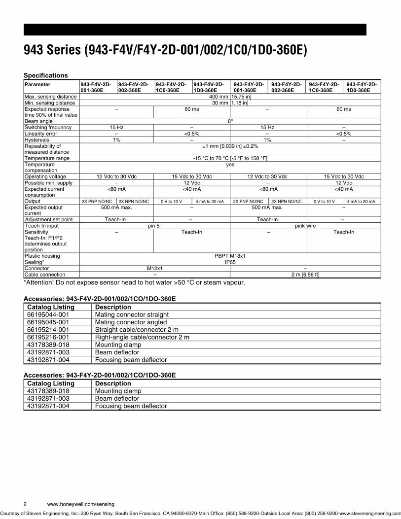
943 Series (943-F4V/F4Y-2D-001/002/1C0/1D0-360E)
Ultrasonic Distance Sensors
DESCRIPTION The new 943-F4V (connector) and 943-F4Y (cable) Series industrial sensors are the latest additions to our range of ultrasonic distance sensors. They offer improved scanning ranges and remote Teach-In of the switching or analog outputs, in addition to new, advanced features, such as Window and Hysteresis modes. The devices are Teach-In compatible and have an M18 plastic housing.
FEATURES • Non contact distance sensing for use in non invasive
measurement • Reduced sensitivity to light intensity/reflectivity/opacity of
target for enhanced flexibility and certainty of measurement • Detects over much longer distance than other detection
methods reducing the need for close proximity to the target • Presence absence, tank fill level and diameter
measurement provides an extremely robust and flexible measurement method
• Short distance (in ultrasonic terms) for enhanced accuracy, repeatability (material independent) measurement to 30 mm [1.18 in].
•
POTENTIAL APPLICATIONS • Reel diameter measurement • Tank level measurement • Presence/absence of an object • Loop control • Product height measurement • Tire manufacturing
Courtesy of Steven Engineering, Inc.-230 Ryan Way, South San Francisco, CA 94080-6370-Main Office: (650) 588-9200-Outside Local Area: (800) 258-9200-www.stevenengineering.com
943 Series (943-F4V/F4Y-2D-001/002/1C0/1D0-360E)
2 www.honeywell.com/sensing
Specifications Parameter 943-F4V-2D-
001-360E 943-F4V-2D-002-360E
943-F4V-2D-1C0-360E
943-F4V-2D-1D0-360E
943-F4Y-2D-001-360E
943-F4Y-2D-002-360E
943-F4Y-2D-1C0-360E
943-F4Y-2D-1D0-360E
Max. sensing distance 400 mm [15.75 in] Min. sensing distance 30 mm [1.18 in] Expected response time 90% of final value
– 60 ms – 60 ms
Beam angle 8º Switching frequency 15 Hz – 15 Hz – Linearity error – <0.5% – <0.5% Hysteresis 1% – 1% – Repeatability of measured distance
±1 mm [0.039 in] ±0.2%
Temperature range -15 °C to 70 °C [-5 °F to 158 °F] Temperature compensation
yes
Operating voltage 12 Vdc to 30 Vdc 15 Vdc to 30 Vdc 12 Vdc to 30 Vdc 15 Vdc to 30 Vdc Possible min. supply – 12 Vdc – 12 Vdc Expected current consumption
<80 mA <40 mA <80 mA <40 mA
Output 2X PNP NO/NC 2X NPN NO/NC 0 V to 10 V 4 mA to 20 mA 2X PNP NO/NC 2X NPN NO/NC 0 V to 10 V 4 mA to 20 mA
Expected output current
500 mA max. – 500 mA max. –
Adjustment set point Teach-In – Teach-In – Teach-In input pin 5 pink wire Sensitivity Teach-In: P1/P2 determines output position
– Teach-In – Teach-In
Plastic housing PBPT M18x1 Sealing* IP65 Connector M12x1 – Cable connection – 2 m [6.56 ft]
*Attention! Do not expose sensor head to hot water >50 °C or steam vapour. Accessories: 943-F4V-2D-001/002/1CO/1DO-360E Catalog Listing Description 66195044-001 Mating connector straight 66195045-001 Mating connector angled 66195214-001 Straight cable/connector 2 m 66195216-001 Right-angle cable/connector 2 m 43178389-018 Mounting clamp 43192871-003 Beam deflector 43192871-004 Focusing beam deflector
Accessories: 943-F4Y-2D-001/002/1CO/1DO-360E Catalog Listing Description 43178389-018 Mounting clamp 43192871-003 Beam deflector 43192871-004 Focusing beam deflector
Courtesy of Steven Engineering, Inc.-230 Ryan Way, South San Francisco, CA 94080-6370-Main Office: (650) 588-9200-Outside Local Area: (800) 258-9200-www.stevenengineering.com
Ultrasonic Distance Sensors
Honeywell Sensing and Control 3
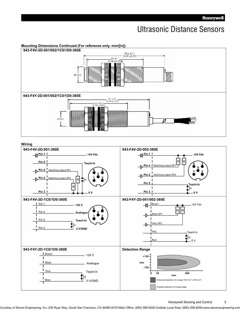
Mounting Dimensions Continued (For reference only. mm/[in]) 943-F4V-2D-001/002/1C0/1D0-360E
943-F4Y-2D-001/002/1C0/1D0-360E
Wiring
943-F4V-2D-001-360E 943-F4V-2D-002-360E Pin 1
Pin 5
+24 Vdc
Teach-In
Switching output SP1
0 V
Pin 4
Pin 2
Pin 3
Switching output SP2
R
R 1 2
345
Pin 1
Pin 5
+24 Vdc
Switching output SP1
0 V
Pin 4
Pin 2
Pin 3
Switching output SP21 2
345
RR
Teach-In
943-F4V-2D-1C0/1D0-360E 943-F4Y-2D-001/002-360E
Pin 1
Pin 4
+24 V
Pin 5
Pin 3
15
34
2
0 V/GND
Analogue
Teach-In
+24 Vdc
0 V
R R
Grey SP2
Black SP1
Teach-InPink
Brown
Blue
943-F4Y-2D-1C0/1D0-360E Detection Range
+24 V
Pink
Blue 0 V/GND
Analogue
Teach-In
Black
Brown
+130
-130
mm
0 30 400
Enhanced detection of a target 100 mm² x 100 mm²
Possible detection of a large target
mm
Courtesy of Steven Engineering, Inc.-230 Ryan Way, South San Francisco, CA 94080-6370-Main Office: (650) 588-9200-Outside Local Area: (800) 258-9200-www.stevenengineering.com

Automation and Control Solutions Sensing and Control
Honeywell
1985 Douglas Drive North
Minneapolis, MN 61032
www.honeywell.com/sensing
004452-1-1-EN IL50 GLO Printed in USA February 2006 Copyright © 2006 Honeywell International Inc. All rights reserved.
WARNING PERSONAL INJURY DO NOT USE these products as safety or emergency stop
devices or in any other application where failure of the
product could result in personal injury.
Failure to comply with these instructions could result in death or serious injury.
WARRANTY/REMEDY Honeywell warrants goods of its manufacture as being free of
defective materials and faulty workmanship. Honeywell’s
standard product warranty applies unless agreed to otherwise
by Honeywell in writing; please refer to your order
acknowledgement or consult your local sales office for specific
warranty details. If warranted goods are returned to Honeywell
during the period of coverage, Honeywell will repair or replace,
at its option, without charge those items it finds defective. The foregoing is buyer�s sole remedy and is in lieu of all other warranties, expressed or implied, including those of merchantability and fitness for a particular purpose. In no event shall Honeywell be liable for consequential, special, or indirect damages.
While we provide application assistance personally, through
our literature and the Honeywell web site, it is up to the
customer to determine the suitability of the product in the
application.
Specifications may change without notice. The information we
supply is believed to be accurate and reliable as of this
printing. However, we assume no responsibility for its use.
WARNING MISUSE OF DOCUMENTATION • The information presented in this product sheet is for
reference only. Do not use this document as a product
installation guide.
• Complete installation, operation, and maintenance
information is provided in the instructions supplied with
each product.
Failure to comply with these instructions could result in death or serious injury.
SALES AND SERVICE Honeywell serves its customers through a worldwide network
of sales offices, representatives and distributors. For
application assistance, current specifications, pricing or name
of the nearest Authorized Distributor, contact your local sales
office or:
E-mail: [email protected]
Internet: www.honeywell.com/sensing
Phone and Fax: Asia Pacific +65 6355-2828
+65 6445-3033 Fax
Europe +44 (0) 1698 481481
+44 (0) 1698 481676 Fax
Latin America +1-305-805-8188
+1-305-883-8257 Fax
USA/Canada +1-800-537-6945
+1-815-235-6847
+1-815-235-6545 Fax
Courtesy of Steven Engineering, Inc.-230 Ryan Way, South San Francisco, CA 94080-6370-Main Office: (650) 588-9200-Outside Local Area: (800) 258-9200-www.stevenengineering.com
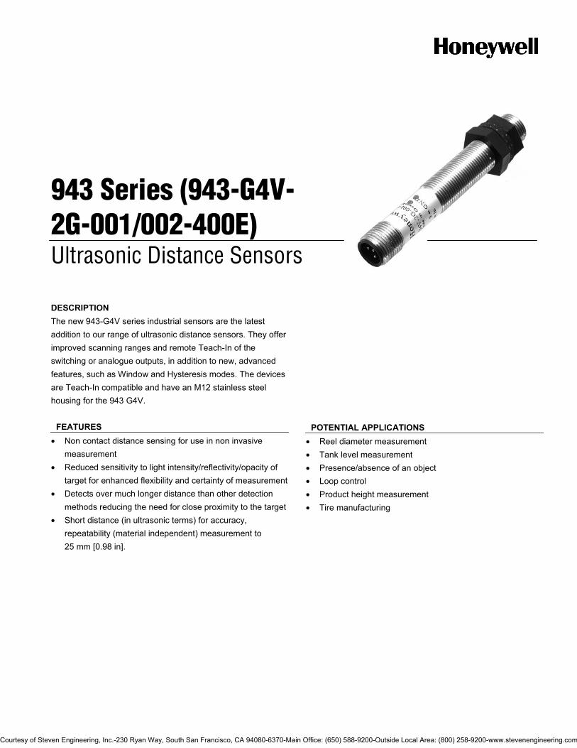
943 Series (943-G4V-2G-001/002-400E)
Ultrasonic Distance Sensors
DESCRIPTION The new 943-G4V series industrial sensors are the latest addition to our range of ultrasonic distance sensors. They offer improved scanning ranges and remote Teach-In of the switching or analogue outputs, in addition to new, advanced features, such as Window and Hysteresis modes. The devices are Teach-In compatible and have an M12 stainless steel housing for the 943 G4V.
FEATURES • Non contact distance sensing for use in non invasive
measurement • Reduced sensitivity to light intensity/reflectivity/opacity of
target for enhanced flexibility and certainty of measurement • Detects over much longer distance than other detection
methods reducing the need for close proximity to the target • Short distance (in ultrasonic terms) for accuracy,
repeatability (material independent) measurement to 25 mm [0.98 in].
POTENTIAL APPLICATIONS
• Reel diameter measurement • Tank level measurement • Presence/absence of an object • Loop control • Product height measurement • Tire manufacturing
Courtesy of Steven Engineering, Inc.-230 Ryan Way, South San Francisco, CA 94080-6370-Main Office: (650) 588-9200-Outside Local Area: (800) 258-9200-www.stevenengineering.com

943 Series (943-G4V-2G-001/002-400E)
2 www.honeywell.com/sensing
Specifications Parameter 943-G4V-2G-001-400E 943-G4V-2G-002-400E Max. sensing distance 250 mm [9.84 in] Min. sensing distance 25 mm [0.98 in] Switching frequency 30 Hz Hysteresis 1% Beam angle 8° Repeatability 0,3 mm [0.012 in] Temperature range -20 °C to 70 °C [-4 °F to 158 °F] Operating voltage 10 Vdc to 30 Vdc Expected current consumption <100 mA Output PNP NO/NC NPN NO/NC Expected output current 100 mA max. Adjustment set point Teach-In Stainless steel housing M12x1 Sealing* IP65 Connector M12x1
*Attention! Do not expose sensor head to hot water >50 °C or water vapour. Accessories Catalog Listing Description 66195044-001 Mating connector straight 66195045-001 Mating connector angled
Mounting Dimensions (For reference only. mm/[in])
Courtesy of Steven Engineering, Inc.-230 Ryan Way, South San Francisco, CA 94080-6370-Main Office: (650) 588-9200-Outside Local Area: (800) 258-9200-www.stevenengineering.com
Ultrasonic Distance Sensors
Honeywell Sensing and Control 3
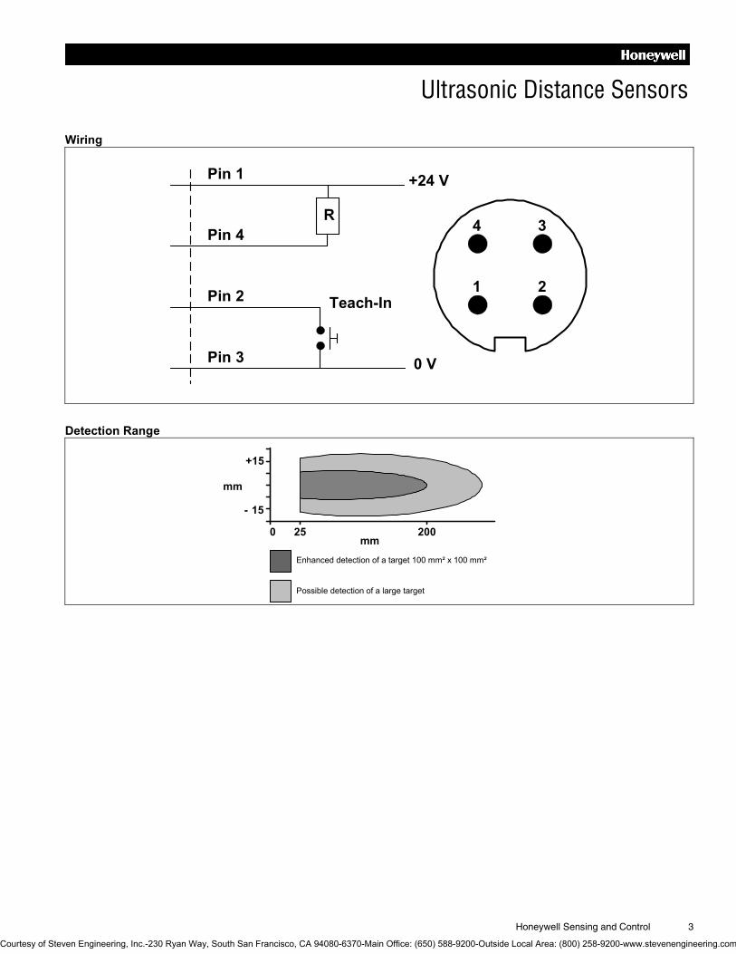
Wiring
Pin 1
Pin 4
Pin 2
Pin 3
+24 V
Teach-In
0 V
R
1 2
34
Detection Range
+15
- 15
mm
0 25 200
Enhanced detection of a target 100 mm² x 100 mm²
Possible detection of a large target
mm
Courtesy of Steven Engineering, Inc.-230 Ryan Way, South San Francisco, CA 94080-6370-Main Office: (650) 588-9200-Outside Local Area: (800) 258-9200-www.stevenengineering.com

Automation and Control Solutions Sensing and Control
Honeywell
1985 Douglas Drive North
Minneapolis, MN 55422
www.honeywell.com/sensing
004449-1-EN IL50 GLO Printed in USA February 2006 Copyright © 2006 Honeywell International Inc. All rights reserved.
WARNING PERSONAL INJURY DO NOT USE these products as safety or emergency stop
devices or in any other application where failure of the
product could result in personal injury.
Failure to comply with these instructions could result in death or serious injury.
WARRANTY/REMEDY Honeywell warrants goods of its manufacture as being free of
defective materials and faulty workmanship. Honeywell’s
standard product warranty applies unless agreed to otherwise
by Honeywell in writing; please refer to your order
acknowledgement or consult your local sales office for specific
warranty details. If warranted goods are returned to Honeywell
during the period of coverage, Honeywell will repair or replace,
at its option, without charge those items it finds defective. The foregoing is buyer�s sole remedy and is in lieu of all other warranties, expressed or implied, including those of merchantability and fitness for a particular purpose. In no event shall Honeywell be liable for consequential, special, or indirect damages.
While we provide application assistance personally, through
our literature and the Honeywell web site, it is up to the
customer to determine the suitability of the product in the
application.
Specifications may change without notice. The information we
supply is believed to be accurate and reliable as of this
printing. However, we assume no responsibility for its use.
WARNING MISUSE OF DOCUMENTATION • The information presented in this product sheet is for
reference only. Do not use this document as a product
installation guide.
• Complete installation, operation, and maintenance
information is provided in the instructions supplied with
each product.
Failure to comply with these instructions could result in death or serious injury.
SALES AND SERVICE Honeywell serves its customers through a worldwide network
of sales offices, representatives and distributors. For
application assistance, current specifications, pricing or name
of the nearest Authorized Distributor, contact your local sales
office or:
E-mail: [email protected]
Internet: www.honeywell.com/sensing
Phone and Fax: Asia Pacific +65 6355-2828
+65 6445-3033 Fax
Europe +44 (0) 1698 481481
+44 (0) 1698 481676 Fax
Latin America +1-305-805-8188
+1-305-883-8257 Fax
USA/Canada +1-800-537-6945
+1-815-235-6847
+1-815-235-6545 Fax
Courtesy of Steven Engineering, Inc.-230 Ryan Way, South San Francisco, CA 94080-6370-Main Office: (650) 588-9200-Outside Local Area: (800) 258-9200-www.stevenengineering.com
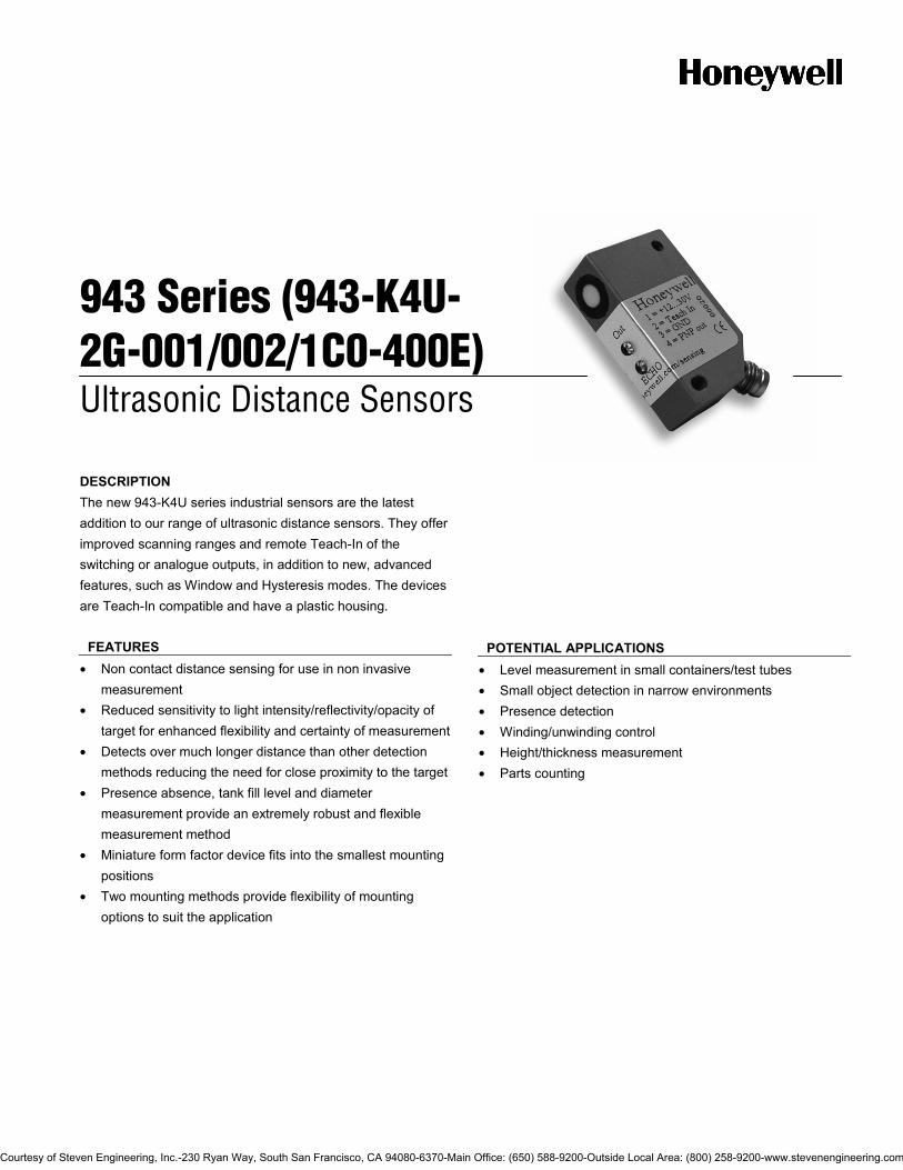
943 Series (943-K4U-2G-001/002/1C0-400E)
Ultrasonic Distance Sensors
DESCRIPTION The new 943-K4U series industrial sensors are the latest addition to our range of ultrasonic distance sensors. They offer improved scanning ranges and remote Teach-In of the switching or analogue outputs, in addition to new, advanced features, such as Window and Hysteresis modes. The devices are Teach-In compatible and have a plastic housing.
FEATURES • Non contact distance sensing for use in non invasive
measurement • Reduced sensitivity to light intensity/reflectivity/opacity of
target for enhanced flexibility and certainty of measurement • Detects over much longer distance than other detection
methods reducing the need for close proximity to the target • Presence absence, tank fill level and diameter
measurement provide an extremely robust and flexible measurement method
• Miniature form factor device fits into the smallest mounting positions
• Two mounting methods provide flexibility of mounting options to suit the application
POTENTIAL APPLICATIONS
• Level measurement in small containers/test tubes • Small object detection in narrow environments • Presence detection • Winding/unwinding control • Height/thickness measurement • Parts counting
Courtesy of Steven Engineering, Inc.-230 Ryan Way, South San Francisco, CA 94080-6370-Main Office: (650) 588-9200-Outside Local Area: (800) 258-9200-www.stevenengineering.com
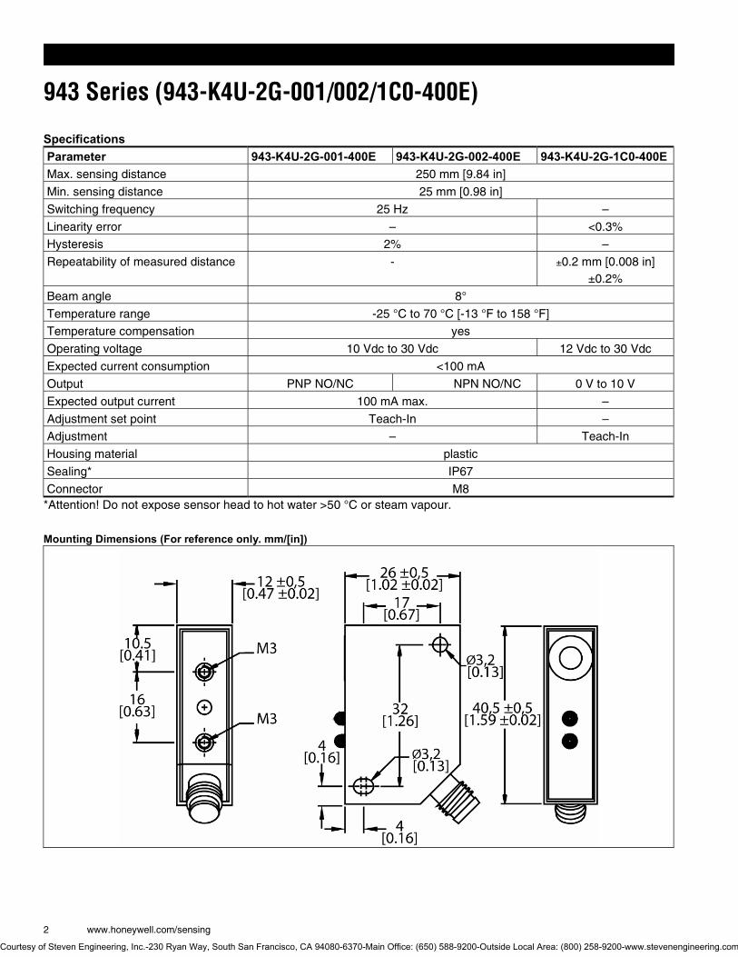
943 Series (943-K4U-2G-001/002/1C0-400E)
2 www.honeywell.com/sensing
Specifications Parameter 943-K4U-2G-001-400E 943-K4U-2G-002-400E 943-K4U-2G-1C0-400EMax. sensing distance 250 mm [9.84 in]
Min. sensing distance 25 mm [0.98 in]
Switching frequency 25 Hz –
Linearity error – <0.3%
Hysteresis 2% –
Repeatability of measured distance - ±0.2 mm [0.008 in] ±0.2%
Beam angle 8°
Temperature range -25 °C to 70 °C [-13 °F to 158 °F]
Temperature compensation yes
Operating voltage 10 Vdc to 30 Vdc 12 Vdc to 30 Vdc
Expected current consumption <100 mA
Output PNP NO/NC NPN NO/NC 0 V to 10 V
Expected output current 100 mA max. –
Adjustment set point Teach-In –
Adjustment – Teach-In
Housing material plastic
Sealing* IP67
Connector M8 *Attention! Do not expose sensor head to hot water >50 °C or steam vapour.
Mounting Dimensions (For reference only. mm/[in])
Courtesy of Steven Engineering, Inc.-230 Ryan Way, South San Francisco, CA 94080-6370-Main Office: (650) 588-9200-Outside Local Area: (800) 258-9200-www.stevenengineering.com

Ultrasonic Distance Sensors
Honeywell Sensing and Control 3
Wiring 943-K4U-2G-001-400E 943-K4U-2G-002-400E 943-K4U-2G-1C0-400E
Pin 1
Pin 2
Pin 4
Pin 3
+24 V
Teach-In
Switching output
0 V
1 3
42
R
Pin 1
Pin 2
Pin 4
Pin 3
+24 V
Teach-In
0 V
1 3
42R
Pin 1
Pin 2
Pin 4
Pin 3
+24 V
Teach-In
0 V
R 1 3
42
Detection Range
+15
- 15
mm
0 25 250
Enhanced detection of a target 100 mm² x 100 mm²
Possible detection of a large target
mm
Courtesy of Steven Engineering, Inc.-230 Ryan Way, South San Francisco, CA 94080-6370-Main Office: (650) 588-9200-Outside Local Area: (800) 258-9200-www.stevenengineering.com
Automation and Control Solutions Sensing and Control
Honeywell
1985 Douglas Drive North
Minneapolis, MN 55422
www.honeywell.com/sensing
004450-1-EN IL50 GLO Printed in USA February 2006 Copyright © 2006 Honeywell International Inc. All rights reserved.
WARNING PERSONAL INJURY DO NOT USE these products as safety or emergency stop
devices or in any other application where failure of the
product could result in personal injury.
Failure to comply with these instructions could result in death or serious injury.
WARRANTY/REMEDY Honeywell warrants goods of its manufacture as being free of
defective materials and faulty workmanship. Honeywell’s
standard product warranty applies unless agreed to otherwise
by Honeywell in writing; please refer to your order
acknowledgement or consult your local sales office for specific
warranty details. If warranted goods are returned to Honeywell
during the period of coverage, Honeywell will repair or replace,
at its option, without charge those items it finds defective. The foregoing is buyer�s sole remedy and is in lieu of all other warranties, expressed or implied, including those of merchantability and fitness for a particular purpose. In no event shall Honeywell be liable for consequential, special, or indirect damages.
While we provide application assistance personally, through
our literature and the Honeywell web site, it is up to the
customer to determine the suitability of the product in the
application.
Specifications may change without notice. The information we
supply is believed to be accurate and reliable as of this
printing. However, we assume no responsibility for its use.
WARNING MISUSE OF DOCUMENTATION • The information presented in this product sheet is for
reference only. Do not use this document as a product
installation guide.
• Complete installation, operation, and maintenance
information is provided in the instructions supplied with
each product.
Failure to comply with these instructions could result in death or serious injury.
SALES AND SERVICE Honeywell serves its customers through a worldwide network
of sales offices, representatives and distributors. For
application assistance, current specifications, pricing or name
of the nearest Authorized Distributor, contact your local sales
office or:
E-mail: [email protected]
Internet: www.honeywell.com/sensing
Phone and Fax: Asia Pacific +65 6355-2828
+65 6445-3033 Fax
Europe +44 (0) 1698 481481
+44 (0) 1698 481676 Fax
Latin America +1-305-805-8188
+1-305-883-8257 Fax
USA/Canada +1-800-537-6945
+1-815-235-6847
+1-815-235-6545 Fax
Courtesy of Steven Engineering, Inc.-230 Ryan Way, South San Francisco, CA 94080-6370-Main Office: (650) 588-9200-Outside Local Area: (800) 258-9200-www.stevenengineering.com

948 Series (948-ISY-2D-001/002/003/004-180E)
Ultrasonic Distance Sensors
DESCRIPTION The 948 Series is one of the smallest ultrasonic scan through devices in the world. Its small, rectangular, IP67-rated plastic housing makes it easy to install in limited space applications. The sensor consists of two parts, a transmitter and a receiver. It is especially suited for food and beverage applications, in particular bottle counting.
FEATURES • Thru-scan detection regardless of the object material for
enhanced detection
• Non contact distance sensing for use in non invasive measurement
• Reduced sensitivity to light intensity/reflectivity/opacity of target for enhanced flexibility and certainty of measurement
• Detects over much longer distance than other detection methods reducing the need for close proximity to the target
• Presence absence, tank fill level and diameter measurement provides an extremely robust and flexible measurement method
POTENTIAL APPLICATIONS
• Food and beverage machinery and equipment • Rapid presence/absence detection: bottle counting • Loop control
Courtesy of Steven Engineering, Inc.-230 Ryan Way, South San Francisco, CA 94080-6370-Main Office: (650) 588-9200-Outside Local Area: (800) 258-9200-www.stevenengineering.com

948 Series (948-ISY-2D-001/002/003/004-180E)
2 www.honeywell.com/sensing
Specifications Parameter 948-ISY-2D-001-180E 948-ISY-2D-002-180E 948-ISY-2D-003-180E 948-ISY-2D-004-180E Sensing distance 1100 mm [3.61 ft] Response time on/off 3 ms Beam angle 15º Output NO PNP NO NPN NC PNP NC NPN Expected output current 500 mA Switching frequency 150 Hz Temperature range -15 °C to 60 °C [-5 °F to140 °F] Operating voltage 18 Vdc to 30 Vdc Expected current consumption
<40 mA
Housing plastic Sealing IP67 Cable connection 2 m [6.56 ft]
Sensor consists of 2 parts: 1 transmitter and 1 receiver.
With flat targets best results may be achieved with an angle 30° object-ultrasonic beam.
Courtesy of Steven Engineering, Inc.-230 Ryan Way, South San Francisco, CA 94080-6370-Main Office: (650) 588-9200-Outside Local Area: (800) 258-9200-www.stevenengineering.com
Ultrasonic Distance Sensors
Honeywell Sensing and Control 3
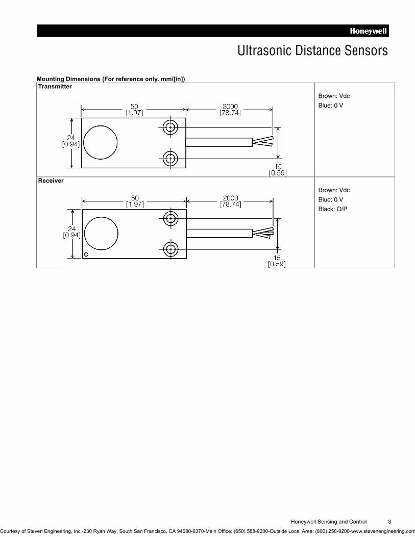
Mounting Dimensions (For reference only. mm/[in]) Transmitter
Brown: Vdc
Blue: 0 V
Receiver
Brown: Vdc
Blue: 0 V
Black: O/P
Courtesy of Steven Engineering, Inc.-230 Ryan Way, South San Francisco, CA 94080-6370-Main Office: (650) 588-9200-Outside Local Area: (800) 258-9200-www.stevenengineering.com

Automation and Control Solutions Sensing and Control
Honeywell
1985 Douglas Drive North
Minneapolis, MN 55422
www.honeywell.com/sensing
004448-1-EN IL50 GLO Printed in USA February 2006 Copyright © 2006 Honeywell International Inc. All rights reserved.
WARNING PERSONAL INJURY DO NOT USE these products as safety or emergency stop
devices or in any other application where failure of the
product could result in personal injury.
Failure to comply with these instructions could result in death or serious injury.
WARRANTY/REMEDY Honeywell warrants goods of its manufacture as being free of
defective materials and faulty workmanship. Honeywell’s
standard product warranty applies unless agreed to otherwise
by Honeywell in writing; please refer to your order
acknowledgement or consult your local sales office for specific
warranty details. If warranted goods are returned to Honeywell
during the period of coverage, Honeywell will repair or replace,
at its option, without charge those items it finds defective. The foregoing is buyer�s sole remedy and is in lieu of all other warranties, expressed or implied, including those of merchantability and fitness for a particular purpose. In no event shall Honeywell be liable for consequential, special, or indirect damages.
While we provide application assistance personally, through
our literature and the Honeywell web site, it is up to the
customer to determine the suitability of the product in the
application.
Specifications may change without notice. The information we
supply is believed to be accurate and reliable as of this
printing. However, we assume no responsibility for its use.
WARNING MISUSE OF DOCUMENTATION • The information presented in this product sheet is for
reference only. Do not use this document as a product
installation guide.
• Complete installation, operation, and maintenance
information is provided in the instructions supplied with
each product.
Failure to comply with these instructions could result in death or serious injury.
SALES AND SERVICE Honeywell serves its customers through a worldwide network
of sales offices, representatives and distributors. For
application assistance, current specifications, pricing or name
of the nearest Authorized Distributor, contact your local sales
office or:
E-mail: [email protected]
Internet: www.honeywell.com/sensing
Phone and Fax: Asia Pacific +65 6355-2828
+65 6445-3033 Fax
Europe +44 (0) 1698 481481
+44 (0) 1698 481676 Fax
Latin America +1-305-805-8188
+1-305-883-8257 Fax
USA/Canada +1-800-537-6945
+1-815-235-6847
+1-815-235-6545 Fax
Courtesy of Steven Engineering, Inc.-230 Ryan Way, South San Francisco, CA 94080-6370-Main Office: (650) 588-9200-Outside Local Area: (800) 258-9200-www.stevenengineering.com