ultrasonic surgical aspirator system - integra life
TRANSCRIPT

Integra®CUSA® NXT Operator’s Manual
Integra® CUSA® NXTUltrasonic Surgical Aspirator System
OPERATOR’S MANUAL
0877085 -1 72904051, Issue E
For more information or to place an order, please contact:Integra n 311 Enterprise Drive, Plainsboro, NJ 08536USA and Canada: 800.997.4868 n 609.936.5400 (Outside USA) 888.980.7742 (Fax)integralife.com
Integra LifeSciences (Ireland) LimitedIDA Business and Technology ParkSraghTullamore, County Offaly, Ireland
Integra® CU
SA® N
XT
Operator’s M
anual

Publication Name:CUSA® NXT Operator’s Manual
Integra Part Number: 72904051 Rev. EEffective Date: January 2018
Trademark Acknowledgements:Integra, the Integra logo, CUSA and Selector are registered trademarks of Integra LifeSciences Corporation or its subsidiaries in the United States and/or other countries. SaberTip and MicroTip are trademarks of Integra LifeSciences Corporation or its subsidiaries. Bemis and Hi-Flow are trademarks of Bemis Manufacturing Company. Cidex and Nu-Cidex are trademarks of Johnson & Johnson. Hibicet and Hibitane are trademarks of Regent Medical Limited. RECEPTAL is a trademark of Hospira, Inc.
Copyright Information:© 2018 Integra LifeSciences Corporation. All Rights Reserved. No part of this document may be reproduced, stored in a retrieval system, or transmitted, in any form or by any means - electronic, mechanical, photocopying, recording, or otherwise - without the expressed, written consent of Integra LifeSciences. Additional copies of this document can be ordered from Integra LifeSciences.
Integra LifeSciences (Ireland) Limited.IDA Business & Technology ParkSraghTullamoreCounty OffalyIreland
www.integralife.com
Caution
Federal (USA) law restricts this device to sale by or on the order of a physician.
0086

This page is intentionally left blank.

i
TABLE OF CONTENTS
Chapter 1: Patient and Operating Room SafetySystem Overview ....................................................................................................................................1
Intended Use ..................................................................................................................................1
Contraindications............................................................................................................................1
Intended Users........................................................................................................................................2
Warnings, Cautions and Notices.............................................................................................................3
Patient and Operating Room Safety...............................................................................................3
CUSA NXT System Setup and Components..................................................................................3
Using the Console, Service Module, and Handpieces ...................................................................5
Preparing the CUSA NXT System for Surgery ...............................................................................6
Operating the CUSA NXT System During Surgery ........................................................................8
Disassembly and Sterilization of CUSA NXT System ....................................................................8
Use of System in MRI Environments..............................................................................................9
Troubleshooting the CUSA NXT System......................................................................................10
Technical Specifications ...............................................................................................................10
Classification and System Symbols ......................................................................................................10
Tubing Pathway Symbols .............................................................................................................14
Footswitch Symbols......................................................................................................................16
Chapter 2: CUSA® NXT System Setup and ComponentsUnpacking and Installing the System ....................................................................................................17
Commissioning the System ..........................................................................................................18
Initial Setup of Console with the Service Module .........................................................................19
List of CUSA NXT Components ............................................................................................................20
About the Console ........................................................................................................................20
About the Footswitch ....................................................................................................................21
About the Service Module ............................................................................................................21
About the Handpieces and Wrench Sets ..............................................................................................23
Handpieces...................................................................................................................................23
Wrench Sets .................................................................................................................................23
About the Tubing Kits ............................................................................................................................24
About the Sterile and Non-Sterile Tips..................................................................................................25
For Neuro Handpieces .................................................................................................................25
For Standard Handpieces.............................................................................................................26
Summary of Operating Safety Precautions...........................................................................................27
ii
Using the Handpieces.................................................................................................................. 27
Sterilizing Backup Handpieces .................................................................................................... 28
Warnings and Hazards when Using the System.......................................................................... 28
Requirements for Servicing the System....................................................................................... 31
Explosion and Fire Hazards......................................................................................................... 31
Latex Information ......................................................................................................................... 31
Chapter 3: Using the Console, Service Module, and HandpiecesAbout the Console Functionality ........................................................................................................... 33
About the Left Console Panel ...................................................................................................... 34
About the Rear Console Panel .................................................................................................... 35
Connecting Handpieces to the Console....................................................................................... 36
Using the Footswitch Pedals ................................................................................................................ 36
Using the Touch Screen Monitor .......................................................................................................... 38
Status/Alarm Symbols.................................................................................................................. 39
Adjusting the Ultrasonic Control Scales....................................................................................... 41
Verifying General Ultrasonic Information ..................................................................................... 43
Displaying Menus for Prime Mode, Customized Settings, and Online Help ................................ 44
About the Service Module Functionality ............................................................................................... 44
About the Handpiece Functionality....................................................................................................... 47
List of Handpieces ................................................................................................................................ 47
List of Standard Handpieces........................................................................................................ 48
List of Neurosurgical Handpieces ................................................................................................ 50
List of MicroSurgical Handpieces................................................................................................. 54
Chapter 4: Preparing the CUSA® NXT System for SurgeryList of Requirements............................................................................................................................. 55
Assembling the Handpieces ................................................................................................................. 56
Preparing the System ........................................................................................................................... 59
Prepare the Suction Source......................................................................................................... 59
Prepare the IV Bag ...................................................................................................................... 60
Prepare the Tubing Kits ............................................................................................................... 60
Connect Tubing to Console ......................................................................................................... 62
Position the Footswitch ................................................................................................................ 63
Priming the Handpieces ....................................................................................................................... 63
Testing the Alarm Tone ........................................................................................................................ 65
Chapter 5: Operating the CUSA® NXT System During SurgeryOperating the System During Surgery.................................................................................................. 67

iii
Warnings Relating to the Tips During Surgery ......................................................................................69
Customizing the User Settings..............................................................................................................70
Chapter 6: Disassembly and Sterilization of CUSA® NXT SystemDismantling the System After Surgery ..................................................................................................73
Cleaning the Handpieces After Surgery ................................................................................................75
Disassembling the Handpieces ....................................................................................................75
Sterilizing Components and Maintaining the Handpieces.....................................................................77
Recommended Sterilization Procedures ......................................................................................77
Disinfecting the Handpieces .........................................................................................................78
Maintaining the Handpieces .........................................................................................................79
Maintaining the Touch Screen Monitor .................................................................................................80
Safety Guidelines .........................................................................................................................80
Cleaning Guidelines .....................................................................................................................80
Handling and Transporting the System.................................................................................................81
Console with Service Module .......................................................................................................81
Console without Service Module ..................................................................................................81
Shipping Instructions ....................................................................................................................82
Chapter 7: Troubleshooting the CUSA® NXT SystemAbout the Troubleshooting Process ......................................................................................................83
Problems Powering the System On and Off .........................................................................................83
Responding to Alarms...........................................................................................................................84
Troubleshooting Aspiration Problems ...................................................................................................85
Troubleshooting Irrigation Problems .....................................................................................................86
Troubleshooting Ultrasonic Power Problems ........................................................................................87
Appendix A: Technical SpecificationsSpecifications for the CUSA® NXT System...........................................................................................89
Electrical Safety ....................................................................................................................................91
Standards and IEC Classifications........................................................................................................93
Manufacturer’s Declaration Table .........................................................................................................94
Appendix B: WarrantyIntegra Warranty for the CUSA® NXT Ultrasonic Surgical Aspirator.....................................................99
Index .............................................................................................................................. 103

iv
This page is intentionally left blank.

Chapter 1 • Patient and Operating Room Safety • 1
CHAPTER 1 PATIENT AND OPERATING ROOM SAFETY
System Overview ............................................................................................. 1
Intended Users................................................................................................. 2
Warnings, Cautions and Notices.................................................................... 3
Classification and System Symbols ............................................................ 10
System Overview
The CUSA® NXT Ultrasonic Surgical Aspirator System facilitates the removal of tissue. The system provides selective tissue disintegration with simultaneous irrigation and aspiration.
Intended Use
The CUSA NXT Ultrasonic Surgical Aspirator System is indicated for use in surgical procedures where fragmentation, emulsification and aspiration of soft and hard (e.g. bone) tissue is desirable, including Neurosurgery, Gastrointestinal and affiliated organ surgery, Urological surgery, Plastic and Reconstructive surgery, General surgery, Orthopedic surgery, Gynecological surgery, Thoracic surgery, Laparoscopic surgery and Thoracoscopic surgery.
Using this System in Ultrasonic Surgery
The basic operating principle of ultrasonic surgery involves the longitudinal vibration of the hollow handpiece tip at ultrasonic frequency against tissue. The mechanical action of the tip is similar to a tiny “surgical hammer” that breaks off cellular material. When the tip contacts the fluid filled tissue, the resulting slurry of emulsified material from the tissue is aspirated through the center of the handpiece. A slow flow of irrigant around the tip assists in the removal of waste tissue.
The selective action of the instrument arises from the disruption of fluid containing cellular material while fibrous and elastic tissue such as nerves and blood vessels remain relatively unaffected at the ultrasonic frequencies used.
Contraindications
This device is not indicated for and should not be used for the removal of uterine fibroids.
Warning
No modification of this equipment is allowed.

2 • Chapter 1 • Patient and Operating Room Safety
Intended Users
The intended users of this guide and the equipment it describes are qualified medical professionals who are trained in the particular surgical technique and surgical procedure to be performed, and trained in the use of this equipment. The CUSA NXT System should only be used in a surgical environment by qualified medical professionals.
Reviewing the Operator’s Manual
Verify that all surgeons, nurses, and technicians who will be setting up, operating and maintaining the CUSA NXT System review this Operator’s Manual prior to using the system in a surgical procedure. Pay close attention to the operating safety warning, cautions and notices listed in the section Warnings, Cautions and Notices, p. 3. If there are additional questions after reading this manual, contact the technical support staff at Integra LifeSciences.
To draw immediate attention to matters of importance, this guide presents warnings, cautions and notices as follows:
Online Help
On the touch screen monitor, press the help button to display the online help system. Please note that the online help system only provides basic guidelines for performing common CUSA NXT tasks. The online help does not:
• Replace this Operator’s Manual.
• Provide clinical instructions for any specific procedures.
Warning
The Console is only to be used in a hospital environment and by qualified operators and surgeons. Failure to observe this warning could result in serious injury or death.
It is the responsibility of the Healthcare Facility to ensure that intended users of CUSA NXT System are appropriately trained in the use of this equipment.
Warning
Indicates a potentially hazardous situation that, if not avoided, could result in serious injury or death, or product damage.
Caution
Indicates a hazardous situation that, if not avoided, could result in minor or moderate injury, or product damage.
Notice
Indicates a hazard that may result in product damage.

Chapter 1 • Patient and Operating Room Safety • 3
For complete instructions on using the CUSA NXT System, refer to the procedures described in this Operator’s Manual.
Warnings, Cautions and Notices
To promote the safe use of the CUSA NXT System, this section presents the warnings, cautions, and notices that appear throughout this guide.To operate this equipment with maximum safety, it is important that you read, understand and follow the instructions in the warnings, cautions, and notices.
Patient and Operating Room Safety
CUSA NXT System Setup and Components
Warning
No modification of this equipment is allowed.
The Console is only to be used in a hospital environment and by qualified operators and surgeons. Failure to observe this warning could result in serious injury or death.
It is the responsibility of the Healthcare Facility to ensure that intended users of CUSA NXT System are appropriately trained in the use of this equipment.
Warning
Only operate the footswitch when the base of the footswitch is positioned flat on the ground, and the front of the footswitch is facing upwards with the pedals visible and free from obstruction.
TO AVOID RISK OF ELECTRIC SHOCK, THIS EQUIPMENT MUST ONLY BE CONNECTED TO A SUPPLY MAINS WITH PROTECTIVE EARTH.
Only use Integra handpieces and accessories with the CUSA NXT System. The use of non-Integra handpieces or accessories may result in patient injury. Non-Integra handpieces or accessories are not supported and are not covered by warranty.
When you connect the handpiece to the Console, the handpiece becomes a functional surgical device.
When the handpiece is connected to a CUSA NXT System that is powered on, but the handpiece is not in use, keep the handpiece away from the patient. Place the handpiece on a sterile, flat, dry, non-conductive, and highly visible surface.

4 • Chapter 1 • Patient and Operating Room Safety
When pressing the Power Footswitch pedal to operate the handpiece, do not allow the tip of the handpiece to come into contact with any object except for the target tissue at the operating site. Touching the tip while powered can result in personal injury.
The handpiece and handpiece accessories must be sterile before surgical use.
Risk of explosion. Do not use in the presence of flammable anaesthetic gases or other volatile solvents.
• Electrical shock hazard. Do not remove cover.
• Refer servicing to authorized service personnel.
To avoid personal injury or damage to the tip, do not allow the tip of the handpiece to contact any operator or hard surfaces or anything other than the target tissue when powered.
For continued protection against fire and electrical hazard, replace fuse only with same type and rating.
Do not use a damaged handpiece with the CUSA NXT System.This may result in injury to the patient or surgical personnel. A damaged handpiece must be returned to the manufacturer for repair. Do not attempt to dismantle the rear handle sections of the handpieces; it does not contain any serviceable parts.
Use of the handpiece outside of the specified conditions can result in high operating temperatures.
Contact between the unprotected part of the tip and non-target tissue can result in burns.
Use of the handpieces in a damaged condition can result in an electric shock hazard.
Failure to maintain the CUSA NXT System in accordance with the instructions in this manual can compromise safety.
Use the single use CUSA® Selector® tubing, and single use tips and flue sets once only. Re-use may result in a biological hazard.
Use single use tips for a single procedure only. Re-using single use tips may result in tip fragmentation and injure the patient or user.
Caution
If the packaging for a sterile accessory is damaged, do not use the sterile accessory.
Contact of the moving tip against a hard surface, e.g. a metal instrument tray, may damage the tip of the handpiece and require replacing the tip before use. Do not use a handpiece with a broken tip.
Warning

Chapter 1 • Patient and Operating Room Safety • 5
Using the Console, Service Module, and Handpieces
Only use the CUSA Selector wrench kit to tighten tips and extensions on the transducer of the handpiece. Always secure the handle of the handpiece in the holder provided. Never dismantle or assemble the handpiece without placing the handle section of the handpiece in the holder. Failure to comply with this instruction could result in permanent damage to the transducer and will invalidate the warranty.
Do not attempt to clear a blocked handpiece by passing the stylet down the rear inlet of the handpiece. This may result in damage to the handpiece. Always pass the stylet from the tip end.
Do not use a handpiece with a broken tip. Inspect the tip for damage prior to use. If the tip is damaged it may be replaced by the operator.
Do not use dry air sterilization methods involving temperatures in excess of 139 °C (282 °F); this may damage the handpiece.
Do not power up the CUSA Selector handpiece without fully priming the handpiece with irrigant (i.e. irrigant must flow from the tip of the handpiece). Failure to prime the handpiece could result in permanent damage to the handpiece (internal and/or external components) and may induce heat exchange with the patient or user, and cause tissue burns.
Notice
In the event that you need to return a device to Integra, to prevent any damage, use the appropriate packaging material.
To prevent fluid flowing into the vacuum line, only use a canister that has a non return valve.
Caution
Warning
When you connect the handpiece to the Console, the handpiece becomes a functional surgical device.
Ignoring alarms on the CUSA NXT System while continuing to use the system may result in injury to the patient and/or surgical personnel, or equipment damage.
The minimum aspiration level setting is 15%. This ensures proper handpiece cooling and performance. Insufficient aspiration can cause premature handpiece or tip failures and may induce heat exchange with the patient or user, and cause tissue burns.

6 • Chapter 1 • Patient and Operating Room Safety
Preparing the CUSA NXT System for Surgery
Caution
Pressing and releasing the Power pedal too quickly may result in a Handpiece Tip Initialization failure. If this occurs, disconnect the handpiece, verify proper tip assembly, and then reconnect the handpiece and try again.
Do not store anything in the storage area in the back of the Console while the system is running.
Notice
After releasing the Power pedal, the pinch valve operates momentarily to block aspiration and facilitate tissue release from the handpiece tip.
If you press the yellow symbol, the touch screen monitor will display error and problem resolution information. For more information on responding to alarms, see page 84.
The level of ultrasonic power displayed on the scale will only be directed to the handpiece tip when the power Footswitch pedal is pressed fully. Pressing this Footswitch pedal partially will give an actual power output below the setting displayed with the exact value depending on the pedal position.
Note that the system only delivers irrigant to the handpiece tip when you press the Power Footswitch pedal. When you press the Fast Flush Footswitch pedal, the system ignores the irrigation scale setting and instead applies an irrigation fast flush rate of about 50 ml/min to the handpiece.
Only the Console is shipped with a power cord. If a Service Module is employed, this cord must be used for the Service Module instead. A lead comes from the rear door of the Service Module and plugs into the back of the Console.
Warning
Single Use devices are for single patient use only. Do not resterilize, reprocess or re-use. Devices (s) is (are) intended to be used for one procedure only. If reprocessed or re-used this may result in the infection of patient (or patient specimen) through cross-contamination, as well as would incur the risk of modifying the properties and performance of the device, and of increasing the likelihood of complications and/or undesirable effects. Do not use devices which have not been properly sterilized. Once used, devices must be disposed of in accordance with hospital policies.
Using the incorrect wrench set to assemble/disassemble the handpiece may damage the handpiece.
Failure to center the shroud may cause the handpiece to overheat.

Chapter 1 • Patient and Operating Room Safety • 7
Tubing kits must never be connected directly to the vacuum source as contamination will occur.
To avoid injury to surgical personnel, keep fingers away from the pump rollers.
Caution
With correct use of the wrench, it is not possible to over tighten the joint. However, if the joint is not firmly tightened, the handpiece will not function correctly and may be noisy and overheat during use.
Do not power the CUSA Selector handpiece without fully priming the handpiece with irrigant, i.e. irrigant must flow from the tip of the handpiece. Failure to follow this instruction may result in permanent damage to the handpiece (internal and/or external components) and may induce heat exchange with the patient or user, and cause tissue burns.
When using the Console without the Service Module, prior to surgery, place the Console on a solid surface. The surface must be flat, non-slip and free from obstruction.
The manifold tubing utilizes PVC tubing which is known to contain DEHP in a portion of the drainage path. The risk of exposure to pregnant (breast feeding) women, children and peri-pubescent males is not considered significant for the following reason(s): Saline solution running through the tubing, as irrigation, comes into contact with the surgery site during the tissue ablation process. However, the saline is rapidly aspirated back into the tip along with the ablated tissue.
Notice
If you are using either a straight or laparoscopic handpiece, the angled extension is not required.
Write the in-service start date on the contamination guard label before you install it. See page 79 for details on the contamination guard shelf life.
All of the handpiece and tubing kit components in the CUSA NXT System are not manufactured with dry natural rubber or natural rubber latex.
When preparing the tubing set, connect the tubing to the pump prior to attaching the irrigation supply. Attaching the irrigation supply first will fill the tube with saline and affect the priming time.
Do not remove the aspiration filter from the designated port prior to powering off the system.
Warning

8 • Chapter 1 • Patient and Operating Room Safety
Operating the CUSA NXT System During Surgery
Disassembly and Sterilization of CUSA NXT System
Warning
The handpiece and handpiece accessories must be sterile before surgical use.
Touching of the tip of the handpiece by the operator, while the handpiece is powered on, can result in personal injury.
When the handpiece is powered on, contact of the tip with a hard surface (e.g. a metal instrument, tray, staples, clips, instruments, etc) may damage the tip and require replacement before use.
CUSA NXT tips utilize a silicone flue. Compressing the flue against the side of the vibrating surface along the length of the tip can cause excessive heating and potential burns along the surgical path.
Excessive loading of CUSA NXT tips at the surgical site can induce heating due to vibration and acoustic power transmissions into adjacent tissue that may not be easily visualized due to anatomical constraints.
Thermal management of the surgical site with the aid of the appropriate irrigation and aspiration settings is essential.
Avoid excessive lateral loading of CUSA NXT tips This may result in equipment damage and/or injury to the patient or surgical personnel.
Ignoring alarms on the CUSA NXT System while continuing to use the system may result in injury to the patient and/or surgical personnel, or equipment damage.
Caution
Before surgery, apply the brakes locks to all wheels on the Service Module to stop the wheels from rolling.
Do not attempt to clear a blocked handpiece by passing the stylet down the rear inlet of the handpiece. This may result in damage to the handpiece. Always pass the stylet in from the tip end.
Notice
Press the Power pedal prior to applying the tip of the handpiece to tissue. This will ensure that the tip is vibrating before load is applied.
Warning
To avoid injury to surgical personnel, keep fingers away from the pump rollers.
Chapter 1 • Patient and Operating Room Safety • 9
Use of System in MRI Environments
Electric Shock Hazard – Always unplug the CUSA NXT System before cleaning it.
Do not allow fluids to enter the Console or Service Module.
Caution
Validation of the steam cycles described have been conducted, however, it is solely the decision of the hospital to approve the use of these cycles.
Notice
Do not remove the aspiration filter from the designated port prior to powering off the system.
Do not re-use the tubing kit as this compromises sterility and may lead to damage of the Console and/or Service Module.
Do not remove the contamination guard situated in the receptacle bay at the front of the Service Module.
When dismantling and assembling handpieces of different operating frequencies (24 kHz or 35 kHz), care should be taken to ensure that the correct tips are fitted to the correct handle section. This is achieved by following the color coding, bronze for 24 kHz and gold for 35 kHz. Incorrectly fitted handpieces will either be non-functional or may not perform as intended.
If you are using either a straight or laparoscopic handpiece, the angled extension is not required.
Product damage will result if you do not follow these notices when cleaning the handpiece:
• Do not immerse the handpiece cable electrical connector in liquid.
• Do not use ultrasonic or automatic washers.
• Do not use chlorinated substances such as bleach solution.
• Do not clean the handpiece with abrasive cleaners or steel wire wool.
Warning
Warning
The CUSA NXT System cannot be used in an MRI (Magnetic Resonance Imaging) environment.

10 • Chapter 1 • Patient and Operating Room Safety
Troubleshooting the CUSA NXT System
Technical Specifications
Classification and System Symbols
The following symbols appear on the CUSA NXT System:
Notice
If you press the yellow symbol, the touch screen monitor will display error and problem resolution information.
Warning
The power cord on this product contains lead, a chemical known to the State of California, USA, to cause cancer, and birth defects or other reproductive harm. Wash hands after handling. The power cord complies with the DIRECTIVE 2011/65/EU OF THE EUROPEAN PARLIAMENT AND OF THE COUNCIL of 8 June 2011on the restriction of the use of certain hazardous substances in electrical and electronic equipment (recast).
TO AVOID RISK OF ELECTRIC SHOCK, THIS EQUIPMENT MUST ONLY BE CONNECTED TO A SUPPLY MAINS WITH PROTECTIVE EARTH.
Operating the CUSA NXT outside of the specified environmental conditions may result in injury to the patient and/or surgical personnel, or cause damage to the equipment which may result in a delay in patient treatment.
Symbol Description
Warning: When you connect the handpiece to the Console, the handpiece becomes a functional surgical device.
Warning: Dangerous voltage.
Follow instructions for use

Chapter 1 • Patient and Operating Room Safety • 11
Do not insert fingers. Pinch point can cause injury.
While the Console is connected to the Service Module, do not push, lean or rest against the front or sides of the Console. Only use the Service Module handle when moving the Console.
Protective Earth (ground)
Footswitch Connector
The equipment meets type CF (Cardiac Floating) safety standards.
Volume Control: Controls the volume of non-alarm tones emitted by the Console.
Equipotential point
Alternating current
"On" power
"Off" power
Symbol Description
VOLUME

12 • Chapter 1 • Patient and Operating Room Safety
System power off/standby
Waste canister
Intravenous bag
Irrigation
Temperature Limitation: Indicates upper and lower temperature limits.
Humidity Limitations: Indicates upper and lower humidity limits.
Atmospheric Pressure Limitation: indicates upper and lower atmospheric pressure limits.
Manufacturer
Date of Manufacture
Symbol Description

Chapter 1 • Patient and Operating Room Safety • 13
Catalogue Number
Serial Number
Please dispose of in accordance with local regulations for the collection or disposal of waste electrical and electronic equipment.
Recyclable material
Fragile, handle with care
Do not use if package is damaged
Contains Phthalates (DEHP)
Canadian Standards Association (CSA) Certification Mark
MR Unsafe
Symbol Description
SN

14 • Chapter 1 • Patient and Operating Room Safety
Tubing Pathway Symbols
The following symbols define the tubing pathways:
Non-Sterile
Caution, consult accompanying documents
Not manufactured with dry or natural rubber latex
Keep Dry
Do not re-use
Symbol Description
Symbol Description
IV bag; direction of irrigation tubing towards to peristaltic pump.
Irrigation; above peristaltic pump.

Chapter 1 • Patient and Operating Room Safety • 15
Handpiece; direction of tubing assembly to aspiration filter port and pinch valve.
Handpiece; direction of tubing assembly to aspiration filter port.
Aspiration; direction of tubing assembly to pinch valve.
Symbol Description

16 • Chapter 1 • Patient and Operating Room Safety
Footswitch Symbols
The following symbols appear on the footswitch:
Symbol Description
Power pedal
Fast Flush pedal

Chapter 2 • CUSA® NXT System Setup and Components • 17
CHAPTER 2 CUSA®
NXT SYSTEM SETUP AND COMPONENTS
Unpacking and Installing the System .......................................................... 17
List of CUSA NXT Components.................................................................... 20
About the Handpieces and Wrench Sets..................................................... 23
About the Tubing Kits ................................................................................... 24
About the Sterile and Non-Sterile Tips ........................................................ 25
Summary of Operating Safety Precautions................................................. 27
Unpacking and Installing the System
When unpacking the system, inspect the shipment for any signs of damage or loss. If any items are damaged, notify the carrier, the supplier, and retain all shipping cartons for examination.
Verify that the shipping carton(s) contain the following items:
• Console Carton:
• Console
• Power Cord
• NXT Operator’s Guide
• Footswitch
• Service Module Carton (if applicable):
• Service Module
• Contamination Guard
Caution
If the packaging for a sterile accessory is damaged, do not use the sterile accessory.
Notice
In the event that you need to return a device to Integra, to prevent any damage, use the appropriate packaging material.

18 • Chapter 2 • CUSA® NXT System Setup and Components
Commissioning the System
The manufacturer or supplier will normally commission the CUSA® NXT System. For assistance on the installation procedures, contact the supplier.
After commissioning the system, the supplier will provide training on preparing, operating and maintaining the system. This will normally take place as an in-service training course to the appropriate doctors, nurses, and operating departments.

Chapter 2 • CUSA® NXT System Setup and Components • 19
Initial Setup of Console with the Service Module
1. Place Console in the recess on top of the Service Module.
2. Plug the Service Module cord located in the module’s top rear compartment into the power connector (1) on the rear of the Console.
3. Plug one end of the detachable power cord into the Service Module’s power connector (2) on the rear of the module.
4. Connect the aspiration controller cable (3) located in the Service Module’s top rear compartment to the port on the bottom of the Console (4) inside the compartment
5. Tighten both connector screws.
6. Thread the locking thumbwheel located in the Service Module door into the threaded hole on the bottom of the Console inside the compartment. Tighten fully.
1
2
3
4

20 • Chapter 2 • CUSA® NXT System Setup and Components
List of CUSA NXT Components
The CUSA NXT System consists of the Console, Footswitch, and Service Module (if applicable).
About the Console
The Console provides power to the selected ultrasonic handpieces. A touch screen monitor is used to control the aspiration, irrigation and ultrasonic power delivered to handpiece. This touch screen also provides access to the online help system. Note that the Console includes a detachable Power Cord.
For instructions on using the Console, see page 33.
Console
Service Module

Chapter 2 • CUSA® NXT System Setup and Components • 21
Support for Service Module
The Console supports the optional Service Module that provides suction and waste collection (see page 21).
About the Footswitch
The Footswitch contains two pedals for controlling the power (left side, orange) and Fast Flush (right side, blue).
The Footswitch also provides a 6m cord that connects to the Footswitch port located on the rear panel of the Console. For instructions on using the Footswitch pedals, see page 36. Note that the Footswitch is internally sealed and may be cleaned by immersion (see page 74).
The Footswitch is also supplied on its own as a spare part (Part # NXT10001).
About the Service Module
The Service Module provides a convenient source of suction and a holding area for the aseptic waste collection canister. No further utilities are required. This module requires a 115 V or 230 V nominal grounded power supply.
Warning
Only operate the footswitch when the base of the footswitch is positioned flat on the ground, and the front of the footswitch is facing upwards with the pedals visible and free from obstruction.
Power pedal
Fast Flush pedal

22 • Chapter 2 • CUSA® NXT System Setup and Components
The Service Module includes a spare CUSA NXT contamination guard. For instructions on setting up the Service Module, see page 59.
Collecting Waste
A receptacle for collecting waste is required between the CUSA NXT Console and the vacuum source. RECEPTAL® or Bemis® Hi-Flow™ 2000 ml canisters are suggested.
Using Other Suction Source Types
If the CUSA NXT Console will not be used with the Service Module, then the Console will require another suitable source of suction and waste collection. Wall or ceiling mounted vacuum points in the operating room or a free-standing surgical suction unit should operate at a constant vacuum pressure between 560 mmHg and 620 mmHg with a free air flow capacity of more than 42 L/min.
Warning
TO AVOID RISK OF ELECTRIC SHOCK, THIS EQUIPMENT MUST ONLY BE CONNECTED TO A SUPPLY MAINS WITH PROTECTIVE EARTH.

Chapter 2 • CUSA® NXT System Setup and Components • 23
About the Handpieces and Wrench Sets
Handpieces
The CUSA NXT Console supports a range of handpieces:
For the list of CUSA® Selector® handpieces, see page 47. Note that a brush for cleaning the aspiration channel of the handpiece is supplied with each handpiece (part # 1523101).
Note that the handpiece and the initially pre-packaged non-sterile tips and flue(s) are supplied non-sterile and must be disassembled and sterilized before use according to the instructions in Chapter 6.
Wrench Sets
Use the CUSA Selector wrench set when assembling and disassembling the handpiece for cleaning and sterilization. Each handpiece is supplied with an appropriate wrench set.
Each wrench set consists of a stainless steel holder and wrench, connected by a chain. The cut-outs in the holder are sized according to its use with specific handpieces.
Warning
Only use Integra handpieces and accessories with the CUSA NXT System. The use of non-Integra handpieces or accessories may result in patient injury. Non-Integra handpieces or accessories are not supported and are not covered by warranty.
35 kHz Neurosurgery Handpiece

24 • Chapter 2 • CUSA® NXT System Setup and Components
Guidelines for Using the Wrench Sets
Only use the CUSA Selector wrench set to tighten and loosen tips and extensions on the handpiece. Always secure the handle of the handpiece in the holder provided. Never assemble or disassemble the handpiece by holding the handle in your hand as damage may occur to the handpiece.
Types of Wench Sets
The following table provides the list of part numbers for the different wrench sets:
About the Tubing Kits
The CUSA NXT System requires a supply of sterile tubing kits. Sterile tubing kits have a three year shelf life.
For instructions on using the tubing kits, see page 60.
Part # Description
1523072M1 For Standard handpieces 1523000M1, 1523000M2, 1523000M3.
1523072M2 For Laparoscopic handpiece 1523000M6.
1523072M3 For Neuro handpieces 1523000M5, 1523000M7, 1523000M8, 1523000M9.
1529056 For MicroSurgical handpieces 1529000M1, 1529000M2.
Part # Description
1517079 CUSA Selector Tubing Kit, disposable, single use, box of 10 (primary tubing kit)
1529036 CUSA Selector MicroSurgical Tubing Kit, disposable, single use, box of 10
Chapter 2 • CUSA® NXT System Setup and Components • 25
About the Sterile and Non-Sterile Tips
For Neuro Handpieces
Sterile Tip Sets
The CUSA Selector sterile tip sets include a sterilized tip and flue. Sterile tips sets have a five year shelf life. The part numbers are:
(*These sterile tips have a three year shelf life.)
Part # Description
1523225 24 kHz Neuro Long Sterile Tip Set (5 packs. Each pack contains one tip and one flue)
1523215 24 kHz Neuro Short Sterile Tip Set (5 packs. Each pack contains one tip and one flue)
1523216 Selector® SaberTip™ Sterile Tip Set, for 24 kHz Neuro Short only (5 packs. Each pack contains one tip and one flue)
1529165 24 kHz MicroSurgical Sterile Tip Set (5 packs. Each pack contains one tip and one flue)
1523235 35 kHz Neuro Sterile Tip Set (5 packs. Each pack contains one tip and one flue)
1523211 24 kHz Neuro Short Sterile Tip Set (1 tip and 1 flue)
1523221 24 kHz Neuro Long Sterile Tip Set (1 tip and 1 flue)
1523231 35 kHz Neuro Sterile Tip Set (1 tip and 1 flue)
1529161 24 kHz MicroSurgical Sterile Tip Set (1 tip and 1 flue)
*NXT3218 24 kHz Superior Forward Bone Tip Sterile Tip Set (box of 5)
*NXT3218EA 24 kHz Superior Forward Bone Tip Sterile Tip Set (each 1)
*NXT3219 24 kHz Superior Reverse Bone Tip Sterile Tip Set (box of 5)
*NXT3219EA 24 kHz Superior Reverse Bone Tip Sterile Tip Set (each 1)
*NXT3220 24 kHz Inferior Forward Bone Tip Sterile Tip Set (box of 5)
*NXT3220EA 24 kHz Inferior Forward Bone Tip Sterile Tip Set (each 1)
*1523243 35 kHz Extended Length Tip Sterile Tip Set (box of 5)
*1523243EA 35 kHz Extended Length Tip Sterile Tip Set (each 1)

26 • Chapter 2 • CUSA® NXT System Setup and Components
Non-Sterile Tip Sets
The CUSA Selector non-sterile tip sets include a non-sterile tip and flue. Non-sterile tips and flues must sterilized before use according to the instructions in Chapter 6. The part numbers are:
For Standard Handpieces
See page 48 for information on non-sterile tips and flues.
Part # Description
1523067 24 kHz Neuro Tip Set for Neuro Long and Neuro Short (5 packs. Each pack contains one tip and one flue)
1529066 24 kHz MicroSurgical Tip Set (5 packs. Each pack contains one tip and one flue)
1523078 35 kHz Neuro Tip Set (5 packs. Each pack contains one tip and one flue)
1523066 35 kHz Ultrafine MicroTip™ Set (5 packs. Each pack contains 1 tip and 1 flue)
1529064 24 kHz Microsurgical Ultrafine Tip Set (5 packs. Each pack contains 1 tip and 1 flue)
1529063 24 kHz MicroTip™ Set (1 tip/5 flues)
1523064 35 kHz Neuro Tip Set (1 tip/5 flues)
1523056 24 kHz Ultrafine MicroTip™ (1 tip and 1 flue)
1529065 24kHz Microsurgical Ultrafine Tip (1 tip and 1 flue)
1523077 35kHz Ultrafine MicroTip™ ( 1 tip and 1 flue)

Chapter 2 • CUSA® NXT System Setup and Components • 27
Summary of Operating Safety Precautions
The CUSA NXT Ultrasonic Surgical Aspirator System is indicated for use in surgical procedures where fragmentation, emulsification and aspiration of soft and hard (e.g. bone) tissue is desirable, including Neurosurgery, Gastrointestinal and affiliated organ surgery, Urological surgery, Plastic and Reconstructive surgery, General surgery, Orthopedic surgery, Gynecological surgery, Thoracic surgery, Laparoscopic surgery and Thoracoscopic surgery. Please note that this operator’s manual provides information only on operating the system. This manual does not provide instructions for any specific surgical procedure.
It is imperative that the procedures described in this manual are followed carefully. Using the system in any other manner may result in personal injury.
Using the Handpieces
Warning
When you connect the handpiece to the Console, the handpiece becomes a functional surgical device.
Warning
When the handpiece is connected to a CUSA NXT System that is powered on, but the handpiece is not in use, keep the handpiece away from the patient. Place the handpiece on a sterile, flat, dry, nonconductive, and highly visible surface.
Warning
When pressing the Power Footswitch pedal to operate the handpiece, do not allow the tip of the handpiece to come into contact with any object except for the target tissue at the operating site. Touching the tip while powered can result in personal injury.
Warning
The handpiece and handpiece accessories must be sterile before surgical use.

28 • Chapter 2 • CUSA® NXT System Setup and Components
Sterilizing Backup Handpieces
The CUSA Selector handpiece may be sterilized by steam autoclave (see page 77). Integra LifeSciences recommends that a sterile backup handpiece and associated accessories be available for immediate use in the event of any contamination or malfunction during surgery. Make sure to sterilize the appropriate wrench set with the handpiece so the wrench set may be used to assemble the handpiece and tip. The wrench set should be kept sterile so that it may be used to replace the tip, if necessary.
Warnings and Hazards when Using the System
Class 1 Type CF
The CUSA NXT System is Class 1 type CF Patient connected electrically isolated equipment (reference IEC 60601).
Caution
Contact of the moving tip against a hard surface, e.g. a metal instrument tray, may damage the tip of the handpiece and require replacing the tip before use. Do not use a handpiece with a broken tip.
Warning
Risk of explosion. Do not use in the presence of flammable anaesthetic gases or other volatile solvents.
Warning
Electrical shock hazard. Do not remove cover. Refer servicing to authorized service personnel.
Warning
To avoid personal injury or damage to the tip, do not allow the tip of the handpiece to contact any operator or hard surfaces or anything other than the target tissue when powered.
Warning
For continued protection against fire and electrical hazard, replace fuse only with same type and rating.
CautionBiomedical technicians should note that special attachments are required to connect the ultrasonic handpieces to test equipment used for electrical safety testing. Application of a vibrating handpiece to test equipment without these attachments may result in damage to both the test equipment and the handpiece.

Chapter 2 • CUSA® NXT System Setup and Components • 29
Tightening the Handpieces with the Wrench Kits
Clearing Blocked Handpieces
Inspecting Handpiece Tips for Damage
Priming the Handpieces
CautionOnly use the CUSA Selector wrench kit to tighten tips and extensions on the transducer of the handpiece. Always secure the handle of the handpiece in the holder provided. Never dismantle or assemble the handpiece without placing the handle section of the handpiece in the holder. Failure to comply with this instruction could result in permanent damage to the transducer and will invalidate the warranty.
CautionDo not attempt to clear a blocked handpiece by passing the stylet down the rear inlet of the handpiece. This may result in damage to the handpiece. Always pass the stylet from the tip end.
Warning
Do not use a damaged handpiece with the CUSA NXT System.This may result in injury to the patient or surgical personnel. A damaged handpiece must be returned to the manufacturer for repair. Do not attempt to dismantle the rear handle sections of the handpieces; it does not contain any serviceable parts.
CautionDo not use a handpiece with a broken tip. Inspect the tip for damage prior to use. If the tip is damaged it may be replaced by the operator.
CautionDo not use dry air sterilization methods involving temperatures in excess of 139 °C (282 °F); this may damage the handpiece.
Caution
Do not power up the CUSA Selector handpiece without fully priming the handpiece with irrigant (i.e. irrigant must flow from the tip of the handpiece). Failure to prime the handpiece could result in permanent damage to the handpiece (internal and/or external components) and may induce heat exchange with the patient or user, and cause tissue burns.

30 • Chapter 2 • CUSA® NXT System Setup and Components
Components for Single Use Only
The CUSA Selector tubing kit is supplied sterile for single use only. All flues are for single use only.
Notice
To prevent fluid flowing into the vacuum line, only use a canister that has a non return valve.
Warning
Use of the handpiece outside of the specified conditions can result in high operating temperatures.
Warning
Contact between the unprotected part of the tip and non-target tissue can result in burns.
Warning
Use of the handpieces in a damaged condition can result in an electric shock hazard.
Warning
Failure to maintain the CUSA NXT System in accordance with the instructions in this manual can compromise safety.
Warning
Use the single use CUSA Selector tubing, and single use tips and flue sets once only. Re-use may result in a biological hazard.
Warning
Use single use tips for a single procedure only. Re-using single use tips may result in tip fragmentation and injure the patient or user.

Chapter 2 • CUSA® NXT System Setup and Components • 31
Requirements for Servicing the System
Do not remove any instrument covers on the system or touch screen monitor. The CUSA NXT Console contains no user serviceable parts and the system must be serviced only by qualified Integra service engineers. Interference with the Console by any other personnel may invalidate the warranty and may result in injury.
Explosion and Fire Hazards
Latex Information
The components of the CUSA Selector handpieces that directly or indirectly come into contact with the patient are not manufactured with dry natural rubber or natural rubber latex.
Warning
Do not use in the presence of flammable anaesthetic gases or other volatile solvents.

32 • Chapter 2 • CUSA® NXT System Setup and Components
This page is intentionally left blank.

Chapter 3 • Using the Console, Service Module, and Handpieces • 33
CHAPTER 3 USING THE CONSOLE, SERVICE MODULE, AND HANDPIECES
About the Console Functionality ................................................................. 33
Using the Touch Screen Monitor ................................................................. 38
Using the Footswitch Pedals........................................................................ 36
About the Service Module Functionality ..................................................... 44
About the Handpiece Functionality ............................................................. 47
List of Handpieces......................................................................................... 47
About the Console Functionality
The CUSA® NXT Console contains the electronics, pumps, and mechanical parts for providing power to the selected handpiece used during ultrasonic surgery.
To control the setpoint levels and for online help information, the Console uses:
• A touch screen monitor for specifying the aspiration, irrigation, and ultrasonic setpoint levels and for accessing online help. For instructions on using this monitor, see page 38.
• A Footswitch containing two pedals for controlling the ultrasonic power and the rate of irrigation fluid. For instructions on using this Footswitch, see page 36.
For information on the parts of the Console panels, see pages 34 to 35.

34 • Chapter 3 • Using the Console, Service Module, and Handpieces
About the Left Console Panel
The following table describes the components and connection points on the left side of the Console.
1
3
4
5
2
Component Description
1 Irrigation Pump A peristaltic pump that pumps irrigant from the IV bag to the handpiece. This pump clamps into place across the irrigation tube of the disposable tubing set. Note that the direction of tubing connections to the pump are illustrated on the panel.
2 Aspiration Control Port The port designated for the aspiration filter of the tubing kit
3 Pinch Valve A normally open valve where the aspiration tube is routed before connecting to the suction system. When the Power Footswitch pedal is released, this valve closes momentarily and shuts off the suction and facilitates the release of tissue from the tip of the handpiece. When the Fast Flush Footswitch pedal is pressed, this valve closes and stops the aspiration. The valve re-opens when the Fast Flush Footswitch pedal is released.
4 Handpiece Connection Port Connection port for the 24 kHz handpieces only.
5 IV Pole The pole that holds the bag of irrigation fluid. The pole will support a 500 ml or 1000 ml irrigation bag. If a larger bag is used, place the bag on a separate irrigation stand. To raise and lower the pole, adjust the locking nut at the bottom of the pole.

Chapter 3 • Using the Console, Service Module, and Handpieces • 35
About the Rear Console Panel
The following table describes the components and connection points on the rear side of the Console:
1
2
3
4
5
6
Component Description
1 AC Power Inlet An international standard inlet which accepts the power cord supplied with the Console or the power lead if used with the Service Module. An appliance coupler can be used to isolate the system from the mains power source.
Notice: To isolate the CUSA NXT from the AC power supply, you must unplug the Console from the power source.
2 Power Button Turns the CUSA NXT Console on and off.
Notice: When shutting down the system, the button has a blue light which remains on while the system goes through a shut down process. It does not immediately go out when pressed.
3 Cooling Fan Air Outlet Air, used to cool the internal electronic systems, leaves the Console through this grill, which should be kept clear of any obstruction.
4 Footswitch Connection Port
The port designated for the Footswitch plug.
5 Equipotential Point This external ground pin is connected to the main internal instrument grounding point and is used in some countries as the point for attaching a separate grounding lead.This allows for the connection of a Potential Equalization Conductor that provides a connection between the equipment and the potential equalization busbar of the electrical installation (in accordance with the requirements of IEC 60601-1). This is a biomedical function.
6 Volume Control Knob Controls the volume of non-alarm tones emitted by the Console.

36 • Chapter 3 • Using the Console, Service Module, and Handpieces
Connecting Handpieces to the Console
The Console contains 3 color-coded ports for connecting the different types of handpieces. Two of the ports appear on the front panel, while the third port appears on the left panel.
Only connect one handpiece to the system at the same time. If you connect more than one handpiece at the same time, the system generates an alarm, and stops the ultrasonics.
To connect the handpiece, align the red dot on the handpiece plug with the red dot on the handpiece connection point, and gently insert the plug until you hear a clicking sound.
Note the following color codes for each handpiece type:
For instructions on assembling the handpiece, see page 56.
Using the Footswitch Pedals
The Footswitch contains two pedals:
• Power (left, orange)
Warning
When you connect the handpiece to the Console, the handpiece becomes a functional surgical device.
Color Panel Handpiece Type
Red Left 24 kHz
Green Front 35 kHz
Black Front 24 kHz MicroSurgical
35 kHz Handpiece 24 kHz MicroSurgical Handpiece

Chapter 3 • Using the Console, Service Module, and Handpieces • 37
• Fast Flush (right, blue).
To connect the Footswitch to the Console, attach the Footswitch cord to the appropriate port on the rear of the Console panel. Align the red dot on the Footswitch plug with the red dot on the Footswitch connection point, and gently insert the plug until you hear a clicking sound.
Note that the Footswitch is internally sealed and may be cleaned by immersion (see page 74).
Pressing the Power Pedal
Pressing this pedal will:
• Switch on the irrigation at the preset rate indicated on the front panel irrigation display.
• Switch on the ultrasonic power to a level which varies in an approximately linear fashion from zero (when the pedal is not pressed), to the maximum value indicated on the front panel power display (when the pedal is fully pressed).
Notice
After releasing the Power pedal, the pinch valve operates momentarily to block aspiration and facilitate tissue release from the handpiece tip.
Notice
Do not press the ultrasonics Power pedal on the Footswitch during system startup or while connecting components to the Console.
Power
Fast Flush pedal
pedal

38 • Chapter 3 • Using the Console, Service Module, and Handpieces
Activating the Handpiece
To activate the handpiece, press the Power pedal for at least 2 seconds.
Pressing the Fast Flush Pedal
Pressing this pedal will:
• Switch on irrigation at a rate of 50 ml/min. Note that the irrigation setting on the front panel display has no influence upon the irrigation rate when the Fast Flush pedal is pressed independently.
• Stop aspiration (until the pedal is released).
Using the Touch Screen Monitor
The CUSA NXT Console provides a touch screen monitor for viewing and controlling the power, irrigation, and aspiration levels during an ultrasonic case.
Caution
Pressing and releasing the Power pedal too quickly may result in a Handpiece Tip Initialization failure. If this occurs, disconnect the handpiece, verify proper tip assembly, and then reconnect the handpiece and try again.
1
2
3
4

Chapter 3 • Using the Console, Service Module, and Handpieces • 39
This touch screen provides the following tools:
For instructions on maintaining the touch screen, see page 80.
Status/Alarm Symbols
The CUSA NXT System activates an alarm to indicate a technical problem with the system. All alarms on the CUSA NXT are technical, low-priority alarms, for example, mechanical or equipment related. There are no physiological alarms on the CUSA NXT System.
The five symbols that appear on top of the touch screen provide status information on the major ultrasonic components.
Tools Description
1 Status / Alarm Symbols Displays colored symbols to indicate the status of the major ultrasonic components. For specific information, see the page 39.
2 Ultrasonic Control Scales Controls the power, irrigation, and aspiration settings during an ultrasonic case (see page 41).
3 Information Panel Displays general information regarding the accumulated ultrasonic time and the current vacuum levels (see page 43).
4 Menu Buttons Displays menus for priming the handpieces, customizing user settings, and viewing online help (see page 44).
SymbolNormal Status
Alarm Indicator (When Yellow)Alarm Classification
Alarm Priority
Aspiration Signifies an error in the aspiration process.
Technical Low
PowerSignifies an error in the ultrasonic generator.
Technical Low
FootswitchSignifies a fault in the Footswitch or associated wiring.
Technical Low
HandpieceSignifies that a handpiece is not connected.
Technical Low
GeneralSignifies an error in the electronics or power supplies.
Technical Low

40 • Chapter 3 • Using the Console, Service Module, and Handpieces
During normal operation, all the symbols appear green. If an error occurs with any of the major components, an alarm will sound and the respective symbol will turn from green to yellow.
There is no method to silence alarms from the touch screen, therefore, to manually turn off an alarm, you must turn off the Console. If the system shuts down unexpectedly (for example, a power failure) with an alarm activated on the touch screen, the alarm remains activated when you power the system on again.The only method of turning off the alarm on the touch screen is to resolve the corresponding alarm.
Recommended: When you set up the CUSA NXT System for surgery, make sure that the touch screen is always clearly visible to the surgeon in the event of an alarm, and the alarm tone is audible. Remove any obstructions that may block the surgeon’s view of the touch screen.
Alarm Tone
This tone (on/off) sounds when an alarm activates. You cannot adjust the volume of the alarm tones. The alarm tone is less than 78dB.
Warning
Ignoring alarms on the CUSA NXT System while continuing to use the system may result in injury to the patient and/or surgical personnel, or equipment damage.
Notice
If you press the yellow symbol, the touch screen monitor will display error and problem resolution information. For more information on responding to alarms, see page 84.

Chapter 3 • Using the Console, Service Module, and Handpieces • 41
Adjusting the Ultrasonic Control Scales
Use the power, irrigation, and aspiration scales to control the major ultrasonic settings during a case.
Adjusting the Power Level
Use the power scale (orange) to specify the ultrasonic power output (tip amplitude). The power settings range between 10% and 100%. The default power setting is 10%.
Note that raising the power setting will increase the vibration of the handpiece tip and thus increase tissue fragmentation rate. To adjust the power by 5% increments, use the arrows to the right of the scale. To adjust the power by 10% increments, press the segment bars on the scale.
Notice
The level of ultrasonic power displayed on the scale will only be directed to the handpiece tip when the power Footswitch pedal is pressed fully. Pressing this Footswitch pedal partially will give an actual power output below the setting displayed with the exact value depending on the pedal position.

42 • Chapter 3 • Using the Console, Service Module, and Handpieces
Adjusting the Irrigation Level
Use the irrigation scale (blue) to specify the rate of irrigation that will be delivered to the handpiece. The irrigation rate ranges between 2 and 20 ml/minute. The default flow is 3 ml/min. The accuracy of the irrigation flow is +/- 20% of setting or +/-1 ml/min, whichever is greater. To adjust the rate by 1 ml/minute increments, use the arrows to the right of the scale. To adjust the rate by 2 ml/minute increments, press the desired segment on the scale.
Notice
Note that the system only delivers irrigant to the handpiece tip while pressing the Power Footswitch pedal. If pressing the Fast Flush Footswitch pedal, the system ignores the irrigation scale setting and instead applies an irrigation fast flush rate of about 50 ml/min to the handpiece.

Chapter 3 • Using the Console, Service Module, and Handpieces • 43
Adjusting the Aspiration Level
Use the aspiration scale (green) to specify the aspiration rate of the total available suction of the source of vacuum employed. The aspiration rate ranges from 15% to 100%. The default setting for aspiration is 100%. The accuracy of the aspiration rate is +/-50 mm Hg of available aspiration. To adjust the rate by 5% increments, press the arrows to the right of the scale. To adjust the rate by 10% increments, press the segment bars on the scale. Note that typical aspiration rates are between 30% and 100%.
Verifying General Ultrasonic Information
Use the information panel to determine the general status of the current operating modes and equipment selection. This panel provides the following information:
Warning
The minimum aspiration level setting is 15%. This ensures proper handpiece cooling and performance. Insufficient aspiration can cause premature handpiece or tip failures and may induce heat exchange with the patient or user, and cause tissue burns.
Symbol Description
Displays the total accumulated ultrasonic time since the machine was powered on. This value will reset to 00:00 if the machine is turned off for more than 30 minutes.
Displays the current vacuum level from the aspiration source. This level is measured in mm hg units.

44 • Chapter 3 • Using the Console, Service Module, and Handpieces
Displaying Menus for Prime Mode, Customized Settings, and Online Help
Use the menu buttons to access features for priming the handpiece, customizing user settings, and displaying online help. Note the following buttons:
About the Service Module Functionality
The Service Module provides a convenient, mobile base for the CUSA NXT Console, as well as a source of suction and waste collection. It is controlled from the Console and has no user accessible controls.
Button Description
prime Displays the prime panel for priming the handpiece for surgery (see page 63).
settings Displays options for saving customized settings and specifying different languages (see page 70).
help Displays the online help system for accessing information on performing common tasks (see page 2).
Front Rear
1
2
3
4
5
6
7
8

Chapter 3 • Using the Console, Service Module, and Handpieces • 45
The Service Module contains the following components:
Component Description
1 Suction Port In the top center of the front section of the Service Module, there is a protective filter and an attachment point for the suction tubing which leads internally to the vacuum pump. The protective filter (part # NXT00005) should be replaced every six months or earlier if contaminated. Note that this filter is different from the type used in the disposable tubing kit.
2 Container Receptacle The space at the front of the Service Module for accommodating a variety of commercially available waste containers. For instructions on the tubing connections for the canister, see page 59.
3 Castors The Service Module provides four antistatic rotating castors. Unlocked, both front and rear casters roll easily and rotate freely. When locked, the front casters will not roll, and the rear casters will not roll or rotate.
4 Power Lead A short lead with a socket which fits the AC power inlet on the rear panel of the Console. An appliance coupler can be used to isolate the system from the mains power source.
5 Communication Cable A short cable that provides communication from the Console to the Service Module. The cable plugs into the bottom of the Console when it is placed on the Service Module.
6 Storage Area for Footswitch and Power Cord
The enclosure behind the rear door of the Service Module that accommodates the Footswitch and power cord of the Console when the system is not in use.
7 AC Power Inlet An international standard inlet which accepts the power cord supplied with the Console.
8 Power Switch Turns the power to the Service Module on and off. This switch must be turned on to power on the CUSA NXT Console.

46 • Chapter 3 • Using the Console, Service Module, and Handpieces
For instructions on using the Service Module (or other sources for suction and waste removal) during a surgical procedure, see page 59.
Rear View of Console Attached to Service Module
Caution
Do not store anything in the storage area in the back of the Console while the system is running.
Notice
Only the Console is shipped with a power cord. If a Service Module is employed, this cord must be used for the Service Module instead. A lead comes from the rear door of the Service Module and plugs into the back of the Console.
Service Module
Console

Chapter 3 • Using the Console, Service Module, and Handpieces • 47
About the Handpiece Functionality
Each CUSA® Selector® handpiece contains the following components:
For instructions on maintaining the handpieces, see page 77.
List of Handpieces
The following section provides the lists of Standard, Neurosurgical and MicroSurgical handpieces supported by the CUSA NXT System, and the tip, flue and shroud that correspond with each handpiece.
3
4
2
5
1
Components Description
1 Tip The titanium alloy tip is unique to each handpiece, having a designated thread to minimize the possibility of attaching it to the wrong handpiece.
2 Shroud Black heat resistant shrouds that are interconnected by snap-in push fittings with the exception of the laparoscopic handpiece which has a screw thread joint. The shrouds cover one or two titanium alloy parts:
• All handpieces contain a tip.
• Angled handpieces also include an angled extension.
These titanium alloy parts are fitted with screw threads and are removable for cleaning and sterilizing using the appropriate handpiece wrench set.
3 Handle Contains the piezoelectric transducer which includes an array of piezo ceramic elements to convert the power signal from the CUSA NXT Console into mechanical vibration at 24 kHz or 35 kHz depending on the handpiece type.
4 Piezoelectric Transducer (Internal)
Generates negligible heat and requires no external cooling system. Each handpiece conforms to the highest levels of electrical safety. All the handpieces are Type CF (Cardiac Floating) with a patient leakage current of less than 10 A. Note that the rear section of the handpiece does not contain any user-serviceable parts. Under no circumstance should it be tampered with.
5 Flue The tip of the handpiece is covered by a one-piece or two-piece clear flue to protect tissues around the tip and ensure clarity of view during operation.

48 • Chapter 3 • Using the Console, Service Module, and Handpieces
List of Standard Handpieces
24 kHz Straight Handpiece (part # 1523000M1)
24 kHz Angled Handpiece (part # 1523000M2)
Part # Description Picture
-- Transducer assembly
1523013 Standard tip, non-sterile, each 1
1523042 Flue (disposable), non-sterile, single use, box of 20
1523017 Straight shroud, each1
Part # Description Picture
-- Transducer assembly
1523015 Extended Fine Tip, non-sterile, each 1
1523042 Flue (disposable), non-sterile, single use, box of 20
1523049 Angled shroud, each 1
1523033 Angled extension, each 1
1523035 Extension shroud, each 1

Chapter 3 • Using the Console, Service Module, and Handpieces • 49
35 kHz Straight Handpiece (part # 1523000M3)
24 kHz Laparoscopic Handpiece (part # 1523000M6)
About the Laparoscopic Handpieces
The Laparoscopic handpiece is a variant of the standard straight 24 kHz CUSA Selector handpiece in which the front of the handpiece is extended to facilitate its use in laparoscopic surgery. This handpiece has an external diameter along its working length of 10 mm. It can be used with both reusable and disposable 10/10.5 mm trocar introducers.
The Laparoscopic handpiece has been designed for the dissection and selective removal of unwanted tissue in gastrointestinal surgery. When used in a gentle but continuously moving action, it is capable of removing cellular tissue and fat while sparing fibrous structures such as nerves, blood vessels and membranes. Note that the Laparoscopic handpiece is fitted with a clamp at the rear end through which the aspiration/irrigation tube should be passed.
The laparoscopic handpiece is not intended for liposuction procedures.
Part # Description Picture
-- Transducer assembly
1523014 Standard tip, non-sterile, each 1
1523043 Flue (disposable), non-sterile, single use, box of 20
1523018 Straight shroud, each 1
Part # Description Picture
-- Transducer assembly
1523029 Laparoscopic Tip, non-sterile, each 1
1523032 Flue (disposable), non-sterile, single use, box of 20
1523028 Step amplifier, each 1
1523030 Laparoscopic Shroud, each 1
1523031 Laparoscopic Shroud extension, each 1

50 • Chapter 3 • Using the Console, Service Module, and Handpieces
List of Neurosurgical Handpieces
24 kHz Neurosurgical Short Handpiece (part # 1523000M7)Selector
Part # Description Picture
-- Transducer assembly
1523067 24 kHz Ultrafine MicroTip™ Set (includes Flue)non-sterile, 5 packs, where each pack contains 1 tip and 1 flue
1523056 24 kHz Neuro Short Tip Set (1 tip and 1 flue)
1523215 Ultrafine MicroTip™ Set(single-use), sterile, 5 packs, where each pack contains 1 tip and 1 flue
1523216 Selector® SaberTip™(single-use), sterile, box of 5
NXT3218 Superior Forward Bone Cutting Tip, box of 5
NXT3218EA Superior Forward Bone Cutting Tip, each 1
NXT3219 Superior Reverse Bone Cutting Tip, box of 5
NXT3219EA Superior Reverse Bone Cutting Tip, each 1
NXT3220 Inferior Forward Bone Cutting Tip, box of 5
NXT3220EA Inferior Forward Bone Cutting Tip, each 1
1523049 Angled shroud
1523053 Angled extension
Notice
The flues are packed in either a sterile or non-sterile Tip Set.

Chapter 3 • Using the Console, Service Module, and Handpieces • 51
SaberTip for 24 kHz Neurosurgical Short (part #1523216)
The Selector SaberTip is an additional tip available only for the 24 kHz Neurosurgical Short handpiece. This tip is designed specifically to selectively remove hard tissue such as bone. It has an abrasive surface that is oriented superiorly at the distal end of the tip.
For specific information on using this device, see the Selector SaberTip Instructions for Use that comes with the Selector SaberTip.
NXT Bone Tips for the 24 kHz Neurosurgical handpiece (part # 1523000M7)
The NXT Bone Tips are additional tips available only for the 24 kHz Neurosurgical handpiece.
Three types of NXT Bone Tips are available:
• The Superior Forward Bone Tip has an abrasive surface that is oriented superiorly at the distal end of the tip.This tip is principally designed to fragment, emulsify, and aspirate bone generally encountered in surgical approaches.
• The Superior Reverse Bone Tip has an abrasive surface that is oriented superiorly at the distal end of the tip.This tip is principally designed to fragment, emulsify and aspirate bone by withdrawing the surgical tip away from the target area towards the surgeon.
• The Inferior Forward Bone Tip has an abrasive surface that is oriented downward to the surgical tip bend. This tip is principally designed to fragment, emulsify, and aspirate bone generally encountered in surgical approaches.
For specific information on using the NXT Bone Tips, see the Integra®
CUSA®
NXT Bone Tips Instructions for Use that comes with the NXT Bone Tips.
Notice
• The CUSA NXT Bone Tips can only be used with the CUSA NXT System. They cannot be used with the CUSA Selector System.
• The CUSA NXT Bone Tips can only be used with the 24 kHz Neurosurgical handpiece (part # 1523000M7).

52 • Chapter 3 • Using the Console, Service Module, and Handpieces
24 kHz Neurosurgical Long Handpiece (part # 1523000M5)
Part # Description Picture
-- Transducer assembly
1523067 24kHz Ultrafine MicroTip™ Set (single use) non-sterile, 5 packs, where each pack contains 1 tip and 1 flue
1523225 Neuro Long Tip Set (single use) sterile, 5 packs, where each pack contains 1 tip and 1 flue
1523221 24 kHz Neuro Long Sterile Tip Set, 1 tip and 1 flue
1523049 Angled shroud, each 1
1523045 Clear extension flue, each 1
1523052 Angled extension, each 1
Notice
The flues are packed in either a sterile or non-sterile Tip Set.

Chapter 3 • Using the Console, Service Module, and Handpieces • 53
35 kHz Neurosurgical Handpiece (part # 1523000M9)
Part # Description Picture
-- Transducer assembly
1523064 Neuro Tip Set, non-sterile, 1 tip/5 flues
1523235 Neuro Tip Set (single use) sterile, 5 packs, where each pack contains 1 tip and 1 flue
1523231 Neuro Tip Set (single use), sterile, 1 tip and 1 flue
1523243 Extended Length Tip (single use), sterile, box of 5
1523243EA
Extended Length Tip (single use), sterile, each 1
1523060 Angled shroud, each 1
1523058 Angled extension, each 1
Notice
The flue and extension shroud are packaged in either a sterile or non-sterile Tip Set.
Notice
• The Extended Length Tips are compatible with both the CUSA NXT and CUSA Selector Systems.
• The Extended Length Tip can only be used with the 35 kHz NeuroSurgical Handpiece (part # 1523000M9).

54 • Chapter 3 • Using the Console, Service Module, and Handpieces
List of MicroSurgical Handpieces
24 kHz MicroSurgical Handpiece (part # 1529000M2)
Part # Description Picture
-- Transducer assembly
1529066 MicroSurgical Tip Set (single use), non-sterile, 5 packs, where each pack contains 1 tip and 1 flue
1529165 MicroSurgical Tip Set (single use), sterile, 5 packs, where each pack contains 1 tip and 1 flue
1529161 MicroSurgical Tip Set (single use), sterile, 1 tip and 1 flue
1529063 Microsurgical Tip Set, reusable, non sterile, 1 tip / 5 flues
1529024 Angled shroud, each 1
1529043 Angled extension, each 1
Notice
The flues are packed in either a sterile or non-sterile Tip Set.

Chapter 4 • Preparing the CUSA® NXT for Surgery • 55
CHAPTER 4 PREPARING THE CUSA®
NXT SYSTEM FOR SURGERY
List of Requirements ..................................................................................... 55
Assembling the Handpieces......................................................................... 56
Preparing the System.................................................................................... 59
Priming the Handpieces................................................................................ 63
Testing the Alarm Tone................................................................................. 65
List of Requirements
Preparing the CUSA® NXT System for surgery requires the following items:
• Console
• Footswitch
• Service Module or wall suction outlet
• One waste collection canister
• Sterile Tubing Kit
• Sterile intravenous fluid in container (500 ml isotonic saline is recommended)
• Two sterile handpieces that are fitted with tips (one for the procedure and a second one for backup)
• Appropriate handpiece wrench set
The CUSA NXT System requires a minimum of one hour exposure at its operating temperature range before you use it. Make sure that the system is located in the surgical room at least an hour before use.
Warning
Single Use devices are for single patient use only. Do not resterilize, reprocess or re-use. Devices (s) is (are) intended to be used for one procedure only. If reprocessed or re-used this may result in the infection of patient (or patient specimen) through cross-contamination, as well as would incur the risk of modifying the properties and performance of the device, and of increasing the likelihood of complications and/or undesirable effects. Do not use devices which have not been properly sterilized. Once used, devices must be disposed of in accordance with hospital policies.

56 • Chapter 4 • Preparing the CUSA® NXT for Surgery
Assembling the Handpieces
Assemble the CUSA® Selector® handpiece in the sterile field.
All handpieces and non-sterile tips and flues should be disassembled and sterilized prior to use, according to the instructions in Chapter 6:
1. Using the appropriate wrench set, secure Flat 2 (2) of the handpiece into the designated slot of the holder.
2. Using your fingers, screw the silver angled extension into the handle.
3. Using the wrench, tighten the extension by turning it clockwise.
Caution
The manifold tubing utilizes PVC tubing which is known to contain DEHP in a portion of the drainage path. The risk of exposure to pregnant (breast feeding) women, children and peri-pubescent males is not considered significant for the following reason(s): Saline solution running through the tubing, as irrigation, comes into contact with the surgery site during the tissue ablation process. However, the saline is rapidly aspirated back into the tip along with the ablated tissue.
Notice
If you are using either a straight or laparoscopic handpiece, the angled extension is not required.
Caution
With correct use of the wrench, it is not possible to over tighten the joint. However, if the joint is not firmly tightened, the handpiece will not function correctly and may be noisy and overheat during use.
Warning
Using the incorrect wrench set to assemble/disassemble the handpiece may damage the handpiece.
2

Chapter 4 • Preparing the CUSA® NXT for Surgery • 57
4. Reposition the handpiece into the holder, securing Flat 1 (1) of the angled extension into the designated slot of the holder.
5. Using your fingers, screw the tip into the angled extension.
6. Using the wrench, tighten the tip by turning it clockwise.
7. Remove the handpiece from the holder.
8. Attach the black shroud onto the handpiece by centering and aligning the shroud with the silver angled extension.
Warning
Failure to center the shroud may cause the handpiece to overheat.
1

58 • Chapter 4 • Preparing the CUSA® NXT for Surgery
9. Attach the clear flue onto the shroud until firmly placed in position.
See page 36 for information on connecting the handpiece to the Console.
The handpiece is now ready for use.

Chapter 4 • Preparing the CUSA® NXT for Surgery • 59
Preparing the System
Preparing the system for surgery requires setting up the following items:
• Suction source
• IV Bag
• Tubing Kits
• Footswitch
Prepare the Suction Source
1. Depending on the type of suction source being used, do one of the following:
• If the Service Module is being used with the Console, position it in a convenient location outside the sterile field.
• Recommended: Position the Console so that the touch screen is clearly visible to the surgeon at all times and the alarm tone is audible. Remove any obstructions that may block the surgeon’s view of the touch screen. Do not position the Console in a way that blocks access to the mains connector.
• If the Service Module is not being used, place the Console on a solid surface outside the sterile field. Note that the external suction source must operate at a minimum vacuum pressure between 560 mmHg and 620 mmHg with a free air flow capacity more than 42 L/min.
2. If applicable, place a canister liner in the suction canister and connect the tubes in the suction canister.
3. Ensure that a contamination guard is fitted to protect the vacuum pump in the Service Module.
4. Connect tubing from pinch valve (1) to patient waste port on canister.
Caution
When using the Console without the Service Module, prior to surgery, place the Console on a solid surface. The surface must be flat, non-slip and free from obstruction.
Warning
Tubing kits must never be connected directly to the vacuum source as contamination will occur.
Notice
Write the in-service start date on the contamination guard label before you install it. See page 79 for details on the contamination guard shelf life.

60 • Chapter 4 • Preparing the CUSA® NXT for Surgery
5. Connect tubing from the contamination guard (2) to the vacuum port (3) on the canister.
Prepare the IV Bag
1. Lift the IV pole on the rear of the Console to an elevated position and turn the knurled locking ring clockwise to secure the extended section. Place the sterile intravenous fluid container onto the hook at the end of the pole.
2. Place the sterile handpiece and accessories in the sterile field and unwrap.
Prepare the Tubing Kits
1. Open the appropriate tubing kit onto the sterile field and select the desired handpiece(s).
2. Inspect all tubing before use. Note the following:
• For the MicroSurgical handpiece, have the assistant carefully peel back the outer covering of the MicroSurgical tubing kit (#1529036) and offer the sterile contents to the sterile operator.
• For Primary Tubing Kit for Standard handpieces, have the assistant carefully peel back the outer covering of the Primary tubing kit (part#1517079) and offer the sterile contents to the sterile operator.
1
23

Chapter 4 • Preparing the CUSA® NXT for Surgery • 61
3. Retain the yellow stylet and white hose clips in the sterile field.
4. Connect the tubing to the handpieces. Attach the double lumen tube from the standard tubing kit to the irrigation (1) and aspiration (2) ports on the back of the handpiece.
If you are using the MicroSurgical handpieces:
• For the MicroSurgical handpiece, attach the micro tubing kit to the irrigation (1) and aspiration (2) ports on the back of the handpiece. Connect the other end of the tubing to the standard tubing kit.
5. Using the white hose clips supplied with the tubing kit, secure the tubing and handpiece cord.
6. Depending on the Console location, reserve the desired amount of tubing to be used in the sterile field.
7. Hand the remaining tubing to the Console location in the non-sterile area.
Notice
All of the handpiece and tubing kit components in the CUSA NXT System are not manufactured with dry natural rubber or natural rubber latex.
21
Back End of Handpiece
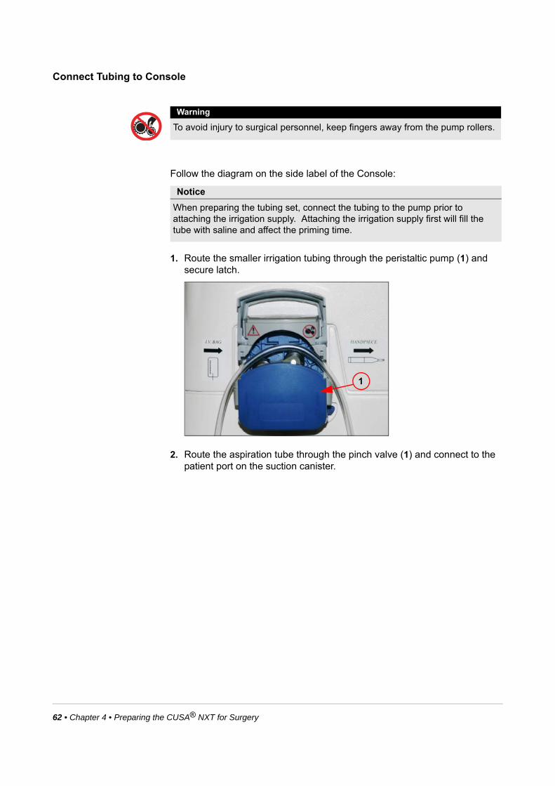
62 • Chapter 4 • Preparing the CUSA® NXT for Surgery
Connect Tubing to Console
Follow the diagram on the side label of the Console:
1. Route the smaller irrigation tubing through the peristaltic pump (1) and secure latch.
2. Route the aspiration tube through the pinch valve (1) and connect to the patient port on the suction canister.
Warning
To avoid injury to surgical personnel, keep fingers away from the pump rollers.
Notice
When preparing the tubing set, connect the tubing to the pump prior to attaching the irrigation supply. Attaching the irrigation supply first will fill the tube with saline and affect the priming time.
1

Chapter 4 • Preparing the CUSA® NXT for Surgery • 63
3. On the left side of the Console, connect the aspiration filter to the designated port (2).
Position the Footswitch
Connect the footswitch, see page 36. Position the footswitch where it is easily accessible to the surgeon.
Priming the Handpieces
Automatic priming is a feature on the CUSA NXT System. Manual methods for priming used with previous versions of Selector may still be performed, however, you must at least start and then stop the initial prime cycle in order to proceed with system operation. If any alarm conditions exist upon initial startup (e.g. handpiece or footswitch not connected), the prime screen will not appear until these alarms are resolved.
Notice
Do not remove the aspiration filter from the designated port prior to powering off the system.
1
2
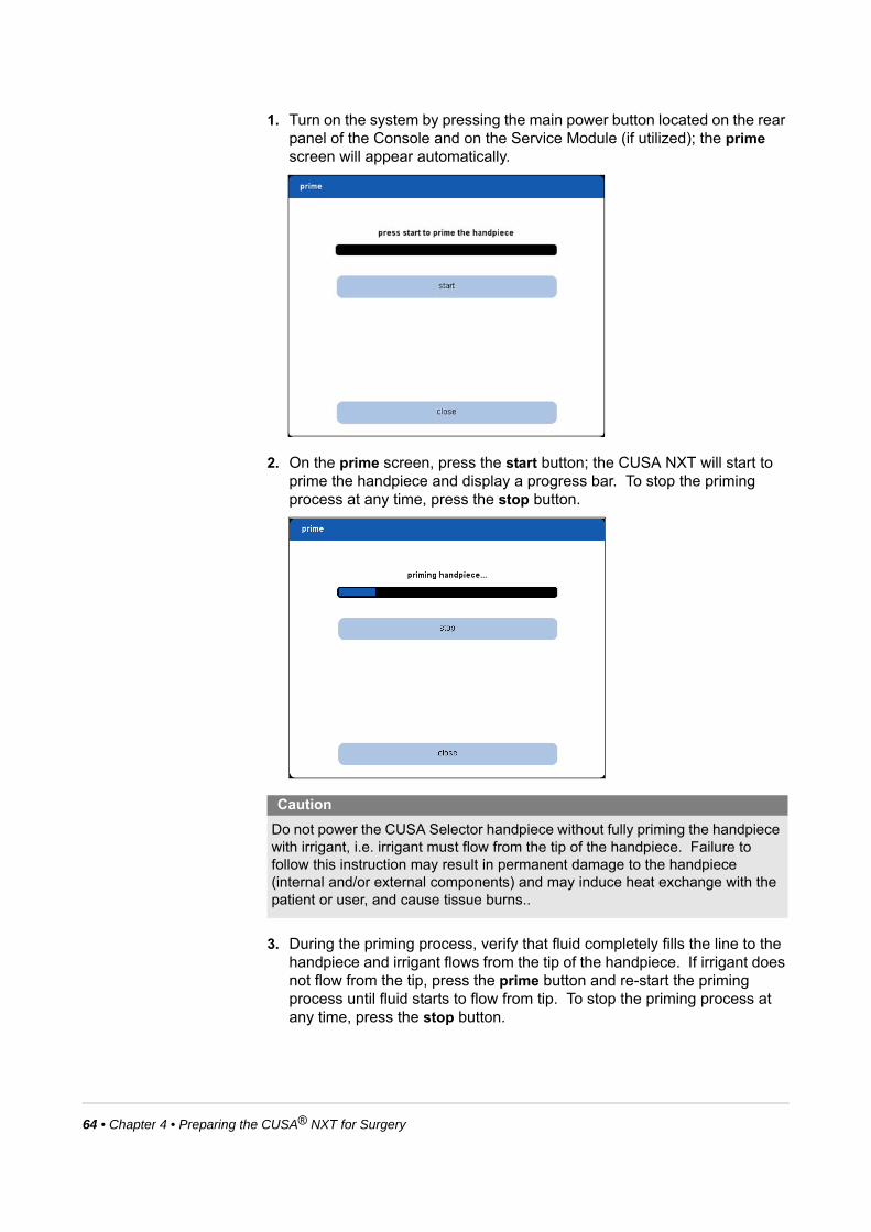
64 • Chapter 4 • Preparing the CUSA® NXT for Surgery
1. Turn on the system by pressing the main power button located on the rear panel of the Console and on the Service Module (if utilized); the prime screen will appear automatically.
2. On the prime screen, press the start button; the CUSA NXT will start to prime the handpiece and display a progress bar. To stop the priming process at any time, press the stop button.
3. During the priming process, verify that fluid completely fills the line to the handpiece and irrigant flows from the tip of the handpiece. If irrigant does not flow from the tip, press the prime button and re-start the priming process until fluid starts to flow from tip. To stop the priming process at any time, press the stop button.
Caution
Do not power the CUSA Selector handpiece without fully priming the handpiece with irrigant, i.e. irrigant must flow from the tip of the handpiece. Failure to follow this instruction may result in permanent damage to the handpiece (internal and/or external components) and may induce heat exchange with the patient or user, and cause tissue burns..

Chapter 4 • Preparing the CUSA® NXT for Surgery • 65
Completing the Priming Process
After priming the handpiece, the main screen will appear. For an overview of main screen, see page 38.
Testing the Alarm Tone
To verify the alarm tone functions correctly, you must intentionally trigger an alarm on the CUSA NXT System, for example, disconnect the footswitch from Console:
1. Disconnect the footswitch from the Console at the footswitch connector.
2. Verify that the footswitch alarm triggers on the system.
3. Verify that the system sounds the alarm tone.
If the alarm tone doesn’t sound, contact your Integra representative.
The system is now ready for use (see Chapter 5).

66 • Chapter 4 • Preparing the CUSA® NXT for Surgery
This page is intentionally left blank.

Chapter 5 • Operating the CUSA® NXT During Surgery • 67
CHAPTER 5 OPERATING THE CUSA®
NXT SYSTEM DURING SURGERY
Operating the System During Surgery ........................................................ 67
Warnings Relating to the Tips During Surgery........................................... 69
Customizing the User Settings..................................................................... 70
Operating the System During Surgery
After setting up the system, the system may be used for surgery.
Note the following guidelines when using the CUSA NXT during surgery:
Warning
The handpiece and handpiece accessories must be sterile before surgical use.
Warning
Ignoring alarms on the CUSA® NXT System while continuing to use the system may result in injury to the patient and/or surgical personnel, or equipment damage.
Caution
Before surgery, apply the brakes locks to all wheels on the Service Module to stop the wheels from rolling.

68 • Chapter 5 • Operating the CUSA® NXT During Surgery
• Increasing the power setting (orange) increases cell disruption at the handpiece tip.
• Increasing the irrigation setting (blue) increases the irrigation flow.
• Increasing the aspiration setting (green) increases the suction at the handpiece tip.
During the surgical procedures, you may adjust these variables by adjusting the appropriate scales on the touch screen.
1. Verify that the handpiece is fully primed.
2. Set the aspiration, irrigation, and power levels to the desired settings. If desired, use the presets option to select the pre-defined settings (see page 71). If there are no saved settings, use the touch screen to set the desired aspiration and irrigation levels. Note the following:
3. Hold the handpiece in the sterile field and verify the following:
• The tip is not in contact with any object.
• The aspiration and irrigation tubes are free from kinks or other obstructions.
4. Press the Power pedal on the Footswitch for at least 2 seconds to activate the handpiece. Verify that a fine aerosol spray of irrigant appears at the tip showing that ultrasonic power is present.
The system is now ready for surgical use.
5. To operate the ultrasonic aspirator, press the Power pedal. Aspiration operates continuously and irrigation is activated at the pre-set level when the pedal is pressed. Ultrasonic power is controlled in a linear fashion - increasing as the Power pedal is pressed further until, at full depression, it reaches the maximum level set on the power display on the front panel.
Levels Description
aspiration Adjust the aspiration scale to the required level.
irrigation Adjust the irrigation scale to the required level. Note that irrigation levels between 2 and 8 ml/min are typically used.
power Adjust the power scale to the required value. Note that power settings between 40% and 100% are typically used.
Notice
In Step 4, pressing and releasing the Power pedal too quickly may result in a Handpiece Tip Initialization failure. If this occurs, disconnect the handpiece, verify proper tip assembly, and then reconnect the handpiece and try again.
Notice
Press the Power pedal prior to applying the tip of the handpiece to tissue. This will ensure that the tip is vibrating before load is applied.

Chapter 5 • Operating the CUSA® NXT During Surgery • 69
6. If the surgeon only wishes to irrigate the operating site, press the Fast Flush Footswitch pedal. Irrigant will flow from the end of the handpiece at a rate of 50 ml/min.
7. If a problem occurs, see Chapter 7 for troubleshooting guidelines.
8. If blockage occurs in the handpiece during operation, use the supplied sterilized nylon stylet to clear it. When using the stylet, pass it into the titanium tip of the handpiece until the blockage is cleared. After clearing the blockage, wash the tip as described in the following section, "Cleaning the Handpiece During Surgery" .
9. If for any reason the Console is powered down for a period of less than 30 minutes and then powered up, the Surgery Mode is immediately accessed, bypassing the normal priming procedure.
Cleaning the Handpiece During Surgery
During intervals of operative use, Integra LifeSciences recommends immersing the tip of the handpiece momentarily into sterile water or saline. This will prevent blood and tissue debris from drying on the inner surfaces of the handpiece and aspiration line and minimize the risk of a blockage in the aspiration system.
Warnings Relating to the Tips During Surgery
Caution
Do not attempt to clear a blocked handpiece by passing the stylet down the rear inlet of the handpiece. This may result in damage to the handpiece. Always pass the stylet in from the tip end.
Warning
Touching of the tip of the handpiece by the operator, while the handpiece is powered on, can result in personal injury.
Warning
When the handpiece is powered on, contact of the tip with a hard surface (e.g. a metal instrument, tray, staples, clips, instruments, etc) may damage the tip and require replacement before use.
Warning
CUSA NXT tips utilize silicone flues. Compressing the flue against the side of the vibrating surface along the length of the tip can cause excessive heating and potential hazard to adjacent tissue, such as burns.

70 • Chapter 5 • Operating the CUSA® NXT During Surgery
Customizing the User Settings
On the main screen, press the settings button to save ultrasonic settings and specify languages for on-screen text.
Note the following settings:
Note the presets settings can be customized depending on surgeon’s needs, while the languages settings are customized prior to shipping.
Warning
Excessive loading of CUSA NXT tips at the surgical site can induce heating due to vibration and acoustic power transmissions into adjacent tissue that may not be easily visualized due to anatomical constraints.
Thermal management of the surgical site with the aid of the appropriate irrigation and aspiration settings is essential.
Warning
Avoid excessive lateral loading of CUSA NXT tips. This may result in equipment damage and/or injury to the patient or surgical personnel.
Settings Description
presets Provides functions for saving and restoring power, irrigation, and aspiration values.
language Provides options for displaying the touch screen content into 5 different languages: English, French, Italian, German, and Spanish.
Chapter 5 • Operating the CUSA® NXT During Surgery • 71
Saving Customized Ultrasonic Settings
Press the presets button to save customized settings or restore the default settings.
To save customized settings for subsequent sessions:
1. Adjust the power, irrigation, and aspiration settings to the desired levels.
2. On the main screen, press the settings button and choose the presets option.
3. On the displayed panel, press the save current set points button. The system will save the current power, irrigation, and aspiration levels. The next time the system is turned on, the CUSA NXT System will restore these values.
To restore the default settings, press presets on the settings panel and choose restore default set points option. The CUSA NXT System will restore the factory settings for the power, irrigation, and aspiration levels.
Specifying Languages for On-screen Text
Press the languages button to specify the language of the onscreen text (English, French, German, Italian, and Spanish).

72 • Chapter 5 • Operating the CUSA® NXT During Surgery
This page is intentionally left blank.

Chapter 6 • Disassembly and Sterilization of CUSA® NXT After Surgery • 73
CHAPTER 6 DISASSEMBLY AND STERILIZATION OF CUSA® NXT SYSTEM
Dismantling the System After Surgery ........................................................ 73
Cleaning the Handpieces After Surgery ...................................................... 75
Sterilizing Components and Maintaining the Handpieces......................... 77
Maintaining the Touch Screen Monitor ....................................................... 80
Handling and Transporting the System....................................................... 81
Dismantling the System After Surgery
After an operative procedure, dismantle the system and prepare it for storage.
1. If the same settings used during the operation may be required for future use, use the preset feature to save them (see page 70).
2. Remove the handpiece from the operating area and flush it by aspirating at least 100 ml of isotonic fluid. Note that the residue from the intravenous fluid container usually provides a convenient source of fluid.
3. Remove the hose clips from the handpiece cable.
4. Disconnect the tubing set from the handpiece.
5. Disconnect the contamination guard tubing from the vacuum port of the canister.
6. Remove the intravenous fluid container from the tubing set and discard.
7. Remove the irrigation tube from the peristaltic pump, the aspiration tube from the pinch valve and the aspiration filter from the Console. If using a disposable liner, remove it from the suction canister and discard together with the entire tubing set. If using a hard canister, discard it with entire tubing kit.
Notice
The handpiece and the initially pre-packaged non-sterile tip and flue(s) are supplied non-sterile and must be disassembled and sterilized before use.
Warning
To avoid injury to surgical personnel, keep fingers away from the pump valve

74 • Chapter 6 • Disassembly and Sterilization of CUSA® NXT After Surgery
8. Turn off the power on the rear panel of the CUSA® NXT Console and Service Module (if utilized). Remove the main power cord from the Console or Service Module as appropriate, wipe clean and store in the rear cupboard of the Service Module (if utilized).
9. Disconnect the Footswitch and wipe clean. If the Footswitch is contaminated with blood or fluid, it may be cleaned by immersing it in warm water containing detergent or disinfectant (the port must be kept dry) and rinsed. Allow the Footswitch to drain after washing and store in the rear storage area of the Service Module (if utilized).
10.Wipe the Console and the Service Module with a clean cloth dampened with warm water and a mild detergent, disinfectant or alcohol when necessary to remove blood or dirt. Lower the irrigation pole by turning the knurled locking ring counter-clockwise.
11. Remove the handpiece cable from the Console and disconnect from the handpiece. Wipe the cable with a clean cloth dampened with warm water and a mild detergent, disinfectant or alcohol when necessary to remove blood or dirt.
Notice
Do not remove the aspiration filter from the designated port prior to powering off the system.
Notice
Do not re-use the tubing kit as this compromises sterility and may lead to damage of the Console and/or Service Module.
Notice
Do not remove the contamination guard situated in the receptacle bay at the front of the Service Module.
Warning
Electric Shock Hazard – Always unplug the CUSA NXT System before cleaning it.
Warning
Do not allow fluids to enter the Console or Service Module.
Notice
When dismantling and assembling handpieces of different operating frequencies (24 kHz or 35 kHz), care should be taken to ensure that the correct tips are fitted to the correct handle section. This is achieved by following the color coding, bronze for 24 kHz and gold for 35 kHz. Incorrectly fitted handpieces will either be non-functional or may not perform as intended.

Chapter 6 • Disassembly and Sterilization of CUSA® NXT After Surgery • 75
Cleaning the Handpieces After Surgery
Disassembling the Handpieces
After surgery and prior to sterilization, disassemble and clean the CUSA® Selector® handpiece:
1. In a sink or bowl, prepare a cleaning solution containing warm water with detergent. This is necessary for cleaning the handpiece parts. Consult hospital policy for approved cleaning materials.
2. Remove and dispose of the clear flue after use, in compliance with the hospital policy for disposal of contaminated waste.
3. Remove the black shroud and place in the cleaning solution.
4. Lay the handpiece in the appropriate wrench holder with the wrench flat secured in the holder cut-out.
5. Using the appropriately sized end of the wrench, loosen the tip by turning it counterclockwise. Unscrew the tip and place it in the cleaning solution. If the tip is single-use only or shows evidence of damage, discard the tip.
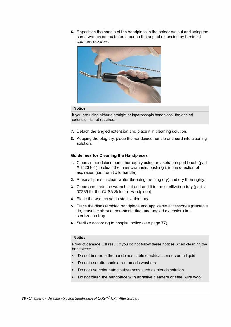
76 • Chapter 6 • Disassembly and Sterilization of CUSA® NXT After Surgery
6. Reposition the handle of the handpiece in the holder cut out and using the same wrench set as before, loosen the angled extension by turning it counterclockwise.
7. Detach the angled extension and place it in cleaning solution.
8. Keeping the plug dry, place the handpiece handle and cord into cleaning solution.
Guidelines for Cleaning the Handpieces
1. Clean all handpiece parts thoroughly using an aspiration port brush (part # 1523101) to clean the inner channels, pushing it in the direction of aspiration (i.e. from tip to handle).
2. Rinse all parts in clean water (keeping the plug dry) and dry thoroughly.
3. Clean and rinse the wrench set and add it to the sterilization tray (part # 07289 for the CUSA Selector Handpiece).
4. Place the wrench set in sterilization tray.
5. Place the disassembled handpiece and applicable accessories (reusable tip, reusable shroud, non-sterile flue, and angled extension) in a sterilization tray.
6. Sterilize according to hospital policy (see page 77).
Notice
If you are using either a straight or laparoscopic handpiece, the angled extension is not required.
Notice
Product damage will result if you do not follow these notices when cleaning the handpiece:
• Do not immerse the handpiece cable electrical connector in liquid.
• Do not use ultrasonic or automatic washers.
• Do not use chlorinated substances such as bleach solution.
• Do not clean the handpiece with abrasive cleaners or steel wire wool.

Chapter 6 • Disassembly and Sterilization of CUSA® NXT After Surgery • 77
Sterilizing Components and Maintaining the Handpieces
Recommended Sterilization Procedures
The handpieces and non-sterile tips and flues must be sterilized before initial use. Handpieces and reusable components are cleaned and sterilized after surgery for next use. Before sterilization, disassemble the handpiece and accessories as described on page 75. Handpieces, reusable tips, and accessories should be cleaned after surgery before sterilization. Note that sterilization systems in use at hospitals are chamber specific. As a result, Integra LifeSciences can only recommend a reference for hospitals to aid the sterilization parameters set for your hospital system. Integra LifeSciences has validated the following sterilization cycles for your consideration.
Steam Sterilization
Place the disassembled handpiece and applicable accessories (reusable tip, reusable shroud, non-sterile flue and extender) into a sterilization tray. Double-wrap the sterilization tray in suitable sterilization grade paper and place fresh filters in the filter ports situated in the top and base of the sterilization tray. Filters must be replaced after each sterilization cycle. Integra LifeSciences also recommends using tamper resistant locks in conjunction with the filters for the unwrapped containers. Place these locks on the handle of the sterilization tray to ensure that the sterility has not been broken.
Wrapping Conditions
Minimum Temperature
Cycle Dwell TimeMinimum Dry Cycle
Double wrapped with filters in the lid and base of container
134 °C (273 °F) Pre-vacuum cycle 3 minutes
10 Minutes
Pre-vacuum cycle 18 minutes
132 °C (270 °F) Pre-vacuum cycle 4 minutes
Double wrapped with the lid removed and filter in the base of container
134 °C (273 °F) Pre-vacuum cycle 3 minutes
10 minutes
Pre-vacuum cycle 18 minutes
132 °C (270 °F) Pre-vacuum cycle 4 minutes

78 • Chapter 6 • Disassembly and Sterilization of CUSA® NXT After Surgery
Cooling Handpieces Before Use
Allow the handpiece to cool completely before use. Note that it is the user’s responsibility to verify that the handpiece and components are completely dry prior to setup.
Validations for Steam Sterilization
Integra LifeSciences has validated steam sterilization. The challenge organism used was > 1 x 10⁶ Bacillus stereothermophilus.
Biological indicators were placed in the areas identified as the most difficult to sterilize, representing worst case conditions.
The biological indicators were inoculated into Tryptone Soya Broth and incubated for seven days. The biological indicators produced no growth, indicating that a Sterility Assurance Level (SAL) of 10-6 was achieved.
Disinfecting the Handpieces
Disinfect the CUSA Selector handpiece in one of the following solutions:
• Glutaraldehyde based solutions such as Cidex® or peracetic acid based solutions such as Nu-Cidex™. Follow the instructions supplied by the manufacturer.
• Solutions of Hibicet™ or Hibitane® in water or ethanol. Follow the instructions supplied by the manufacturer.
Unwrapped with filters in the lid and base of container
134 °C (273 °F) Pre-vacuum cycle 3 minutes
10 minutes
Pre-vacuum cycle 18 minutes
132 °C (270 °F) Pre-vacuum cycle 4 minutes
Unwrapped with filters in the lid and base of container
134 °C (273 °F) Pre-vacuum cycle 18 minutes
20-30 minutes
Wrapping Conditions
Minimum Temperature
Cycle Dwell TimeMinimum Dry Cycle
Caution
Validation of the steam cycles described have been conducted, however, it is solely the decision of the hospital to approve the use of these cycles.
Warning
• Disinfecting solutions containing sodium hypochlorite may cause damage to the metal tip of the handpiece and are not recommended.
• Do not immerse the handpiece cable connector in the disinfecting solution.

Chapter 6 • Disassembly and Sterilization of CUSA® NXT After Surgery • 79
Maintaining the Handpieces
In addition to the post-operative care of the CUSA NXT System described on pages 73 and 75, further maintenance steps recommended by the manufacturer are as follows:
General Maintenance
At 6 Month Intervals
1. Remove and replace the contamination guard every six months, or when the filter changes color (part # NXT00005). Remove and replace silicone hose that connects the suction port on the Service Module to the waste canisters.
2. Examine all shroud sections and replace if damaged.
3. Examine all cable and electrical connectors for signs of excessive wear and damage, and replace if damaged.
Contact Integra Service Center for information on replacing parts.
Preventive Maintenance
At 12 Month Intervals
Integra service personnel should undertake preventative maintenance. In addition to complete cleaning, performance and safety checks on the Console, Service Module, Footswitch and handpieces should be carried out. Full details of these checks are available from the manufacturer or supplier. Contact Integra Service Center for information on returning equipment for service.
Warning
No modification of this equipment is allowed.

80 • Chapter 6 • Disassembly and Sterilization of CUSA® NXT After Surgery
Service Centers
Maintaining the Touch Screen Monitor
Use the following maintenance guidelines to ensure the touch screen functions optimally:
Safety Guidelines
• To reduce the risk of shock, follow all safety notices and never open the touch screen monitor case.
• Turn off the system before cleaning.
• The slots located on the sides and top of the touch screen are for ventilation. Do not block or insert anything inside the ventilation slots.
• Keep the touch screen dry at all times. Do not pour liquid into or onto the touch screen. If the touch screen becomes wet, contact technical support. Do not attempt to repair it yourself.
Cleaning Guidelines
• To clean the touch screen, use window/glass cleaner, eyeglass cleaner, or a quaternary ammonia disinfectant. Put the cleaner on the rag and wipe the touch screen. Never apply cleaner directly to the touch screen.
• Do not use alcohol (methyl, ethyl, or isopropyl) or any strong solvent. Do not use thinner or benzene, abrasive cleaners, or compressed air.
• Do not wipe the touch screen with either a cloth or sponge that could scratch the surface.
Cleaning the Display Cabinet
Use a cloth that is lightly dampened with a mild detergent.
Service Centers Address
United States Integra NeuroSciences5965 Pacific Center Blvd.Suite 714San Diego, CA 92121Tel: 858-455-1115Fax: 858-455-8298E-mail: [email protected]
International Integra NeuroSciencesHalskestrasse 25Ratingen 40880GermanyTel: +49 2102 5535 6150Fax: +49 2102 942 4872E-mail: [email protected]
Chapter 6 • Disassembly and Sterilization of CUSA® NXT After Surgery • 81
Handling and Transporting the System
If you need to move/relocate the CUSA NXT System within the environment of the Healthcare Facility, note the guidelines below.
The CUSA NXT System requires a minimum of one hour exposure at its operating temperature range before you use it; make sure that the system is located in the surgical room at least an hour before use.
Console with Service Module
Before moving the system:
• Unplug the power cord from the wall receptacle and place the power cord in the storage compartment at the rear of the Service Module.
• Disconnect the handpiece.
• Disconnect and remove the irrigation fluid.
• Retract the IV pole.
• Secure any loose objects. Make sure there are no loose objects placed on top of the Console.
• Disconnect the Footswitch and place the Footswitch in the storage compartment at the rear of the Service Module.
When moving the system:
• Push the system using the handle; don’t pull it.
• Do not run whilst pushing the system.
• Use a lift to move the system between floors of a building. Never use a stairwell.
• Do not attempt to lift the system.
To move the system up or down a ramp, use two or more people.
Console without Service Module
Before moving the Console:
• Unplug the power cord from the wall receptacle. Disconnect the power cord from the Console.
• Disconnect the handpiece.
• Disconnect and remove the irrigation fluid.
• Retract the IV pole.
• Secure any loose objects. Make sure there are no loose objects placed on top of the Console.
• Disconnect the footswitch.
When moving the Console (in the immediate environment):
• Lift the Console using the side grips.

82 • Chapter 6 • Disassembly and Sterilization of CUSA® NXT After Surgery
• Place the Console on a solid surface. The surface must be flat, non-slip and free from obstruction.
Shipping Instructions
Clean and sterilize the equipment as per the instructions in Chapter 6. If the equipment is being transported from a hospital, ensure that a Sterilization Certificate is completed and a copy is included within the package.
Handpieces
Place handpiece in a plastic bag and surround with foam/bubble wrap. Pack in a stout cardboard box adding sufficient soft packaging to cushion and protect the contents.
Consoles, Modules and Footswitches
It is recommended that flight cases be used on all occasions for air transportation of the NXT systems. During Service Module handling pallets should also be used. Flight cases can be purchased upon request from Integra.
If you do not have suitable packaging please contact your Integra representative.
Notice
In instances where flight cases are not used please package as described for the Handpieces making sure that the contents will be well protected against dropping and manhandling. It is strongly advised that the original cardboard packaging is only used once for re-packing.

Chapter 7 • Troubleshooting the CUSA® NXT System • 83
CHAPTER 7 TROUBLESHOOTING THE CUSA®
NXT SYSTEM
About the Troubleshooting Process............................................................ 83
Problems Powering the System On and Off ............................................... 83
Responding to Alarms .................................................................................. 84
Troubleshooting Aspiration Problems ........................................................ 85
Troubleshooting Irrigation Problems .......................................................... 86
Troubleshooting Ultrasonic Power Problems............................................. 87
About the Troubleshooting Process
If you encounter problems when using the CUSA® NXT System, first verify that the system is set up correctly. For complete setup instructions, see Chapter 4 in this manual.
About this Chapter
The following sections provide guidelines for troubleshooting and resolving specific problems. If the problems persist, contact technical support for service.
Problems Powering the System On and Off
If the system does not start properly, try rebooting the system:
1. On the back of the Console, press and hold the power button for 6 seconds.
2. Unplug the unit from the wall and then plug it back in.
3. Power up the unit normally.

84 • Chapter 7 • Troubleshooting the CUSA® NXT System
Responding to Alarms
All alarms on the CUSA NXT are low-priority, technical alarms; operator awareness is required.
Symbol Alarm Causes Recommendations
AspirationTubing not attached to suction canister.
Attach the tubing to the suction canister.
Power Improper tip assembly.• Tighten the tip.
• Reconnect the handpiece.
Bad tip.• Replace the tip.
• Reconnect the handpiece.
Handpiece Handpiece not connected.Connect the handpiece to the appropriate port:
• Red 24 kHz
• Green 35 kHz
• Black 24 kHz Microsurgical
Two or more handpieces are connected.
Disconnect extra handpieces.
Footswitch Footswitch not connected.Connect the Footswitch to the rear of Console.
More than one Footswitch pedal is pressed.
Release one Footswitch pedal.
Footswitch pedal is pressed while connecting components to the Console.
Release the Footswitch pedal.
General System General system fault.Restart the system. If the alarm persists, contact technical support.
Notice
If you press the yellow symbol, the touch screen monitor will display error and problem resolution information.

Chapter 7 • Troubleshooting the CUSA® NXT System • 85
Troubleshooting Aspiration Problems
Problem Causes Recommendations
Insufficient Aspiration Service Module is unplugged. Plug in the Service Module.
Tubing is routed incorrectly. See the diagram on the Console for correct routing. Ensure that the filter is fully inserted.
Tubing is not connected to the suction source.
Connect the tubing to the suction source. See page 59.
Aspiration level displayed on the touch screen is too low.
Set aspiration level to appropriate level.
Tubing is blocked or occluded. Unblock tubing with the stylet or saline flush.
Pinch valve not working correctly. Contact technical support.
Suction canister is full. Remove the suction canister and replace with a new one.
Suction canister is cracked. Remove the suction canister and replace with a new one.
Contamination filter is clogged. Check the contamination filter on both the tubing and the Service Module for clogs. If a clog exists, replace the appropriate filter.
Aspiration tubing is pinched or kinked.
Remove the pinch or kink from the tubing.
Hole in the aspiration tubing. Inspect the aspiration tubing for holes. If holes are found, replace the tubing.
Liquid permeates the Footswitch. Replace the Footswitch with a new one.
Excessive Aspiration Tubing between handpiece and Console is blocked or occluded.
Unblock the tubing with the stylet or saline flush.
Handpiece is blocked. Unblock the handpiece with the stylet.
Aspiration is set too high. Reduce the aspiration level setting.
Aspiration pinch valve stays open. Contact technical support.
Aspiration set point level cannot be reduced.
Contact technical support.

86 • Chapter 7 • Troubleshooting the CUSA® NXT System
Troubleshooting Irrigation Problems
Problem Causes Recommendations
Excessive Irrigation Incorrect rate set. Set the appropriate rate (normally between 2 and 6 ml/min).
Tubing is not routed correctly. See the diagram on the Console for the correct routing.
Irrigation pump is not fully closed. Close the irrigation pump.
Broken Fast Flush pedal on the Footswitch.
Replace the Footswitch with a new one.
Irrigation pump is running at an excessive speed.
Contact technical support.
Liquid permeates the Footswitch. Replace the Footswitch with a new one.
Insufficient Irrigation Incorrect rate set. Set the appropriate rate (normally between 2 and 6 ml/min).
Footswitch is unplugged. Plug in the Footswitch.
IV spike is not inserted into the bag. Insert the spike into the IV bag.
IV bag is empty. Replace the IV bag with a new one.
Tubing is not connected to the irrigation pump correctly.
Reconnect the tubing. See page 62.
Tubing is not primed. Prime the tubing. See page 63.
Irrigation tubing is blocked. Inspect the tubing for blockage.
Irrigation tubing is pinched or kinked. Remove the pinch or kink from the tubing.
Hole in the irrigation tubing. Inspect the irrigation tubing for holes. If holes are found, replace the tubing.
Broken Fast Flush pedal on Footswitch.
Replace the Footswitch with a new one.
Pump does not rotate when pressing the Footswitch.
Contact technical support.
Liquid permeates the Footswitch. Replace the Footswitch with a new one.
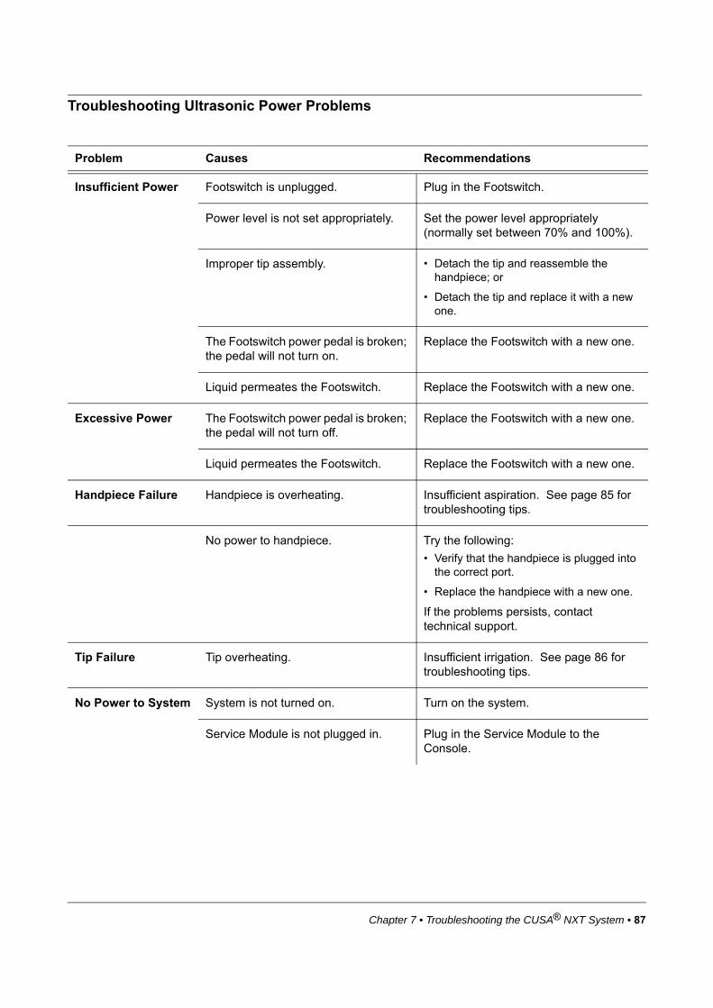
Chapter 7 • Troubleshooting the CUSA® NXT System • 87
Troubleshooting Ultrasonic Power Problems
Problem Causes Recommendations
Insufficient Power Footswitch is unplugged. Plug in the Footswitch.
Power level is not set appropriately. Set the power level appropriately (normally set between 70% and 100%).
Improper tip assembly. • Detach the tip and reassemble the handpiece; or
• Detach the tip and replace it with a new one.
The Footswitch power pedal is broken; the pedal will not turn on.
Replace the Footswitch with a new one.
Liquid permeates the Footswitch. Replace the Footswitch with a new one.
Excessive Power The Footswitch power pedal is broken; the pedal will not turn off.
Replace the Footswitch with a new one.
Liquid permeates the Footswitch. Replace the Footswitch with a new one.
Handpiece Failure Handpiece is overheating. Insufficient aspiration. See page 85 for troubleshooting tips.
No power to handpiece. Try the following:
• Verify that the handpiece is plugged into the correct port.
• Replace the handpiece with a new one.
If the problems persists, contact technical support.
Tip Failure Tip overheating. Insufficient irrigation. See page 86 for troubleshooting tips.
No Power to System System is not turned on. Turn on the system.
Service Module is not plugged in. Plug in the Service Module to the Console.

88 • Chapter 7 • Troubleshooting the CUSA® NXT System
This page is intentionally left blank.

Appendix A • Technical Specifications • 89
APPENDIX A TECHNICAL SPECIFICATIONS
Specifications for the CUSA® NXT System................................................. 93
Electrical Safety ............................................................................................. 91
Standards and IEC Classifications .............................................................. 93
Manufacturer’s Declaration Table ................................................................ 94
Specifications for the CUSA® NXT System
Console Specifications
Service Module Specifications
Parameter Specification
Height 31.8 cm (12.5 in)
Width 45.7 cm (18 in)
Depth 58.9 cm (23.2 in)
Weight 20.9 kg (46 lbs)
Aspiration 15 to 100% of available vacuum
Irrigation 2 to 20 ml/min (accuracy +/- 20% of reading)
Parameter Specification
Height 87.6 cm (34.5 in)
Width 50.3 cm (19.8 in)
Depth 76.6 cm (28.6 in)
Weight 45.4 kg (100 lbs)
Vacuum 635 mmHg
Vacuum Capacity 75 L/min free air minimum

90 • Appendix A • Technical Specifications
Footswitch Specifications
Input Power Source Specifications
Environmental Conditions
Parameter Specification
Height 6 cm (2.4 in)
Width 19.5 cm (7.7 in)
Depth 22 cm (8.7 in)
Weight 2 kg (4.4 lbs)
Length 5.81 m (19 ft)
Parameter Specification
Power Requirements 115-230 V~, 50-60 Hz (Console)115/230 V~, 50-60 Hz/50 Hz (Service Module)
Power Consumption 250 VA Console700 VA Console with Service Module
Parameter Specification
Operating Temperature Range 10º to 35ºC
Storage Temperature Range - 20º to 60ºC
Operating Humidity Range 30% to 75% RH
Storage Humidity Range 25% to 85% RH
Operating Atmospheric Pressure Range 700 to 1100 hPa
Storage Atmospheric Pressure Range 500 to 1100 hPa
Operating Altitude Up to 3000 meters

Appendix A • Technical Specifications • 91
Low Frequency Leakage
Power Cord Specifications
Replace fuses with only those of the same type and rating. For details, see labeling on the rear panel.
Electrical Safety
The CUSA NXT System requires a single grounded electrical outlet providing power at 115 -230 V~, 50-60 Hz (Console),115/230 V~, 50-60 Hz/50 Hz (Service Module) . The Console operates on any voltage between 115 V and 230V. The Service Module has two voltage settings: 115 V and 230 V. The
Warning
Operating the CUSA NXT outside of the specified environmental conditions may result in injury to the patient and/or surgical personnel, or cause damage to the equipment which may result in a delay in patient treatment.
Parameter Leakage
Touch Current < 100 A
Patient Leakage Current < 10 A
AC Power Supply Power Cord Part # Destination
100 - 120 volts NXT80001 USA/Canada
200 - 240 volts NXT80003/NXT80002
UK/Europe
Warning
The power cord on this product contains lead, a chemical known to the State of California, USA, to cause cancer, and birth defects or other reproductive harm. Wash hands after handling. The power cord complies with the DIRECTIVE 2011/65/EU OF THE EUROPEAN PARLIAMENT AND OF THE COUNCIL of 8 June 2011on the restriction of the use of certain hazardous substances in electrical and electronic equipment (recast).

92 • Appendix A • Technical Specifications
voltage setting switch is located inside the rear compartment under the access panel. The access panel displays two stamps, 115 V and 230 V, at opposite corners of the access panel. The position of the access panel determines what voltage the Service Module is set at. The maximum current drawn is 2.5 amps at 240 V and 5 amps at 100 V. The removable power cord supplied with the system provides the power.
Correct grounding of the CUSA NXT Console is essential for safe operation. The Console is grounded via the power cord; verify that this cord is connected to a properly grounded power receptacle of appropriate rating. Only use the power cord supplied with the system since these cords vary according to destination. An external ground point is also located on the rear panel (see page 35).
Warning
TO AVOID RISK OF ELECTRIC SHOCK, THIS EQUIPMENT MUST ONLY BE CONNECTED TO A SUPPLY MAINS WITH PROTECTIVE EARTH.

Appendix A • Technical Specifications • 93
Standards and IEC Classifications
Quality Systems
The CUSA NXT System is manufactured by Integra LifeSciences Corporation. Integra LifeSciences Corporation operates a quality system that complies with ISO 13485, CMDCAS.
International Bodies
The CUSA NXT System has been designed, constructed, and approved to the requirements of the following international bodies:
• International Electrotechnical Commission (IEC)
• Canadian Standards Association (CSA)
Safety Standards
The CUSA NXT System has been independently tested and complies with the following standards:
• CAN/CSA-C22.2 NO.60601-1-08 Medical Electrical Equipment - Part 1: General Requirements for Basic Safety and Essential Performance
• IEC 60601-1:2005 Medical Electrical Equipment: General Requirements for Basic Safety and Essential Performance
• IEC 60601-1-8:2006 Medical Electrical Equipment Part 1-8: General Requirements for Basic Safety and Essential Performance. Collateral Standard: General requirements, tests and guidance for alarm systems in medical electrical equipment and medical electrical systems
• IEC 60601-1-2:2007 Medical electrical equipment: General Requirements for Basic Safety and Essential Performance. Collateral Standard: Electromagnetic Compatibility - Requirements and Tests
Note that the Footswitch is additionally rated IPX8 for moisture resistance.

94 • Appendix A • Technical Specifications
Manufacturer’s Declaration Table
Notice
The CUSA NXT System should not be used adjacent to or stacked with equipment other than the equipment specified in the CUSA NXT System Operator’s Manual. If adjacent or stacked use is necessary, the CUSA NXT System should be observed to verify normal operation in the configuration in which it will be used. The use of accessories, other than the accessories specified in the CUSA NXT System Operator’s Manual may result in increased emissions or decreased immunity of the CUSA NXT System.
Guidance and Manufacturer’s Declaration - Electromagnetic Emissions
The CUSA NXT System is intended for use in the electromagnetic environment specified below. The customer or the user of the CUSA NXT System should assure that it is being used in such an environment.
Emissions Test Compliance Electromagnetic environment - guidance
RF emissions CISPR 11 Group 1 The CUSA NXT System uses RF energy only for its internal function. Therefore, its RF emissions are very low and are not likely to cause any interference in nearby electronic equipment.
RF emissions CISPR 11 Class A The CUSA NXT System is suitable for use in all establishments other than domestic and those directly connected to the public low-voltage power supply network that supplies buildings used for domestic purposes.
Harmonic emissions IEC 61000-3-2 Class A
Voltage fluctuations/flicker emissions IEC 61000-3-3
Complies with Standard
Guidance and Manufacturer’s Declaration - Electromagnetic Immunity
The CUSA NXT System is intended for use in the electromagnetic environment specified below. The customer or the user of the CUSA NXT System should assure that it is being used in such an environment.
Immunity Test IEC 60601 test level Compliance Electromagnetic environment - guidance
Electrostatic discharge (ESD) IEC 61000-4-2
±6 kV contact ±8 kV air
Complies with Standard
Floors should be wood, concrete or ceramic tile. If floors are covered with synthetic material, the relative humidity should be at least 30%.
Electrical fast transient/burst IEC 61000-4-4
±2 kV for power lines ±1 kV for input/output lines
Complies with Standard
Mains power quality should be that of a typical commercial or hospital environment.
Surge IEC 61000-4-5
±1 kV differential mode±2 kV common mode
Complies with Standard
Mains power quality should be that of a typical commercial or hospital environment.

Appendix A • Technical Specifications • 95
Voltage dips, short interruptions and voltage variations or power supply input lines IEC 61000-4-11
• <5 % (>95% dip in ) for 0.5 cycle
• 40% (60% dip in ) for 5 cycles
• 70% UT (30% dip in ) for 25 cycles
• <5% (>95% dip in ) for 5 seconds
Complies with Standard
Mains power quality should be that of a typical commercial or hospital environment. If the user of the CUSA NXT System requires continued operation during power mains interruptions, it is recommended that the CUSA NXT System be powered from an uninterruptible power supply or a battery.
Power frequency (50/60 Hz) magnetic field IEC 61000-4-8
3 A/m / 50 Hz magnetic field
Complies with Standard
Power frequency magnetic fields should be at levels characteristic of a typical location in a typical commercial or hospital environ-ment.
Notice: is the a.c. mains voltage prior to application of the test level.
UrUr
UrUr
UrUr
Ur
Ur

96 • Appendix A • Technical Specifications
Guidance and Manufacturer’s Declaration - Electromagnetic Immunity
The CUSA NXT System is intended for use in the electromagnetic environment specified below. The customer or the user of the CUSA NXT System should assure that it is being used in such an environment.
Immunity Test IEC 60601 test level Compliance Electromagnetic environment - guidance
Conducted RF
IEC 61000-4-6
Radiated RF
IEC 61000-4-3
3 Vrms
150 kHz to 80 MHz
3 V/m
80 MHz to 2,5 GHz
3 Vrms
3 V/m
Portable and mobile RF communications equipment should be used no closer to any part of the CUSA NXT System, including cables, than the recommended separation distance calculated from the equation applicable to the frequency of the transmitter.
Recommended separation distance
80 MHz to 800 MHz
800 MHz to 2,5 GHz
Where P is the maximum output power rating of the transmitter in watts (W) according to the transmitter manufacturer and d is the recommended separation distance in meters (m).
Field strengths from fixed RF transmitters, as determined by an electromagnetic site survey
a
, should be less than the compliance level in each frequency range
b
.
Interference may occur in the vicinity of equipment marked with the following symbol:

Appendix A • Technical Specifications • 97
NOTE 1 At 80 MHz and 800 MHz, the higher frequency range applies.
NOTE 2 These guidelines may not apply in all situations. Electromagnetic propagation is affected by absorption and reflection from structures, objects and people.
a
Field strengths from fixed transmitters, such as base stations for radio (cellular/cordless) telephones and land mobile radios, amateur radio, AM and FM radio broadcast and TV broadcast cannot be predicted theoretically with accuracy. To assess the electromagnetic environment due to fixed RF transmitters, an electromagnetic site survey should be considered. If the measured field strength in the location in which the CUSA NXT System is used exceeds the applicable RF compliance level above, the CUSA NXT System should be observed to verify normal operation. If abnormal performance is observed, additional measures may be necessary, such as re-orientating or relocating the CUSA NXT System.b
Over the frequency range 150 kHz to 80 MHz, field strengths should be less than 3 V/m.
Recommended separation distances betweenportable and mobile RF communications equipment and the CUSA NXT System
The CUSA NXT System is intended for use in an electromagnetic environment in which radiated RF disturbances are controlled. The customer or the user of the CUSA NXT System can help prevent electromagnetic interference by maintaining a minimum distance between portable and mobile RF communications equipment (transmitters) and the CUSA NXT System as recommended below, according to the maximum output power of the communications equipment.
Rated maximum output power of transmitter
W
Separation distance according to frequency of transmitterm
150 kHz to 80 MHz 80 MHz to 800 MHz 800 MHz to 2,5 GHz
0.01 0.12 m 0.12 m 0.24 m
0.1 0.38 m 0.38 m 0.76 m
1 1.2 m 1.2 m 2.4 m
10 3.8 m 3.8 m 7.6 m
100 12 m 12 m 24 m
For transmitters rated at maximum output power not listed above, the recommended separation distance d in metres (m) can be estimated using the equation applicable to the frequency of the transmitter, where P is the maximum output power rating of the transmitter in watts (W) according to the transmitter manufacturer.
NOTE 1 At 80 MHz and 800 MHz, the separation distance for the higher frequency range applies.
NOTE 2 These guidelines may not apply in all situations. Electromagnetic propagation is affected by absorption and reflection from structures, objects and people.

98 • Appendix A • Technical Specifications
This page is intentionally left blank.
Appendix B • Warranty • 99
APPENDIX B WARRANTY
Integra Warranty for the CUSA® NXT Ultrasonic Surgical Aspirator
1. Warranty
1. 1 Duration. The Warranty is provided for one year from the date that the equipment is invoiced to the customer.
1. 2 Coverage. During the Warranty Period, Integra shall provide free-of-charge service and maintenance consistent with the provisions of Section 3 of this Warranty, so that the Equipment conforms with the Specifications defined in the CUSA NXT Ultrasonic Surgical Aspirator Operator's Manual, as such Operator's Manual may be modified by Integra from time to time.
1. 3 Exclusions. The Warranty shall not apply in any manner to service or maintenance of the Equipment, or to replacement of its parts, with respect to:
(i). use of Equipment with any tips, flues, tubing, and accessories other than those manufactured by Integra LifeSciences;
(ii). defects arising out of materials or parts provided, modified or designed by Customer;
(iii). defects emanating from Customer's improper or negligent installation, storage or use of the Equipment or any component thereof, including but not limited to operating the Equipment not in accordance with instructions provided in the Operator's Manual;
(iv). defects arising from improper or negligent cleaning or sterilization methods or improper maintenance of the Equipment;
(v). defects resulting from repairs or service of the Equipment provided other than by Integra or its authorized representatives;
(vi). defects arising from accidental damage to the Equipment, acts of God, electrical power damage, equipment malfunction, unusual stress, unreasonable operating procedures or abnormal or extreme operating conditions; and
(vii). normal wear and tear.
2. Service, Repairs and Replacement.
2. 1 Service and Repairs. All service and repairs covered by this Warranty may be referred to hereinafter as "in-warranty repairs," and all service and repairs not covered by this Warranty may be referred to as "out-of-warranty repairs." Customer shall be responsible to pay Integra's then-standard charges for any out-of-warranty repairs

100 • Appendix B • Warranty
performed by Integra. Integra's sole obligation for Equipment defects and failures of performance shall be to make all necessary adjustments and repairs in accordance with this Warranty.
2. 2 Equipment Replacement. The defective Equipment or part thereof that is replaced in accordance with the Warranty shall be the property of Integra. Integra reserves the right to fill spare parts requests using refurbished sub-assemblies provided that such sub-assemblies are functionally equivalent to new sub-assemblies and carry the same warranty as the replaced sub-assemblies.
2. 3 Notification. In order to avail itself of its rights under the Warranty, Customer must immediately notify Integra of any defects and provide Integra every opportunity to inspect and remedy defects.
3. Repair Parts and Services.
3. 1 Included under the Warranty are the following services:
3. 1.1Consoles and Service Modules. Integra shall, if possible, perform on-site repair of Consoles and service module or replace a Console and service module by a new or refurbished Console and service module (at the discretion of Integra), as the case may be, and where not possible Integra shall arrange and pay to ship the affected Equipment to the designated repair facility, and shall repair the affected Equipment.
3. 1.2Handpieces. Integra shall replace any defective handpieces covered by the Warranty by a new or refurbished handpiece (at the discretion of Integra) that shall carry the same warranty as the original equipment (an "Exchange Handpiece").
3. 2 Modifications to Covered Equipment. From time to time, at its sole discretion, Integra may propose modifications to the covered Equipment and to the specifications for the Equipment ("Specifications"). Subject to Customer's approval and at its sole expense, the Customer may request Integra to make such modifications to the covered Equipment and to the Specifications. Integra shall make such modifications for the Customer, which modifications may include the installation of new parts in the Equipment, at a price equal to the then-current list price for such modifications, as such list price is established by Integra in its sole discretion.
4. Quality Control.
4. 1 Customer shall maintain reasonable standards of quality control, operations, procedures, safety testing and inspection of Equipment to ensure that unnecessary service or maintenance is not required hereunder.

Appendix B • Warranty • 101
4. 2 Customer shall provide a technical counterpart to Integra's Service Agent for assistance in Integra's telephonic diagnosis of the malfunction with the Equipment. Customer shall reasonably accept Integra's determination whether a repair or service is an in-warranty repair or an out-of-warranty repair.
5. Limitation of Liability.
5. 1 THE WARRANTIES DESCRIBED IN SECTION 1 HEREOF ARE EXCLUSIVE AND ARE GIVEN AND ACCEPTED IN LIEU OF ALL OTHER WARRANTIES OF INTEGRA OR ITS SERVICE AGENTS WITH RESPECT TO THE QUALITY, PERFORMANCE AND OPERATION OF THE EQUIPMENT, WRITTEN OR ORAL, EXPRESSED OR IMPLIED, AND WHETHER OR NOT ATTRIBUTABLE TO SERVICE PERFORMED PURSUANT TO THE WARRANTY. ALL OTHER REPRESENTATIONS OR WARRANTIES OF INTEGRA OR ITS REPRESENTATIVES, EXPRESS OR IMPLIED, WITH RESPECT TO THE EQUIPMENT OR THE SERVICES, DIAGNOSES, ADVICE, ASSISTANCE OR PARTS TO BE TENDERED PURSUANT TO THE WARRANTY, INCLUDING, WITHOUT LIMITATION, THOSE OF MERCHANTABILITY AND FITNESS FOR A PARTICULAR PURPOSE, ARE HEREBY EXPRESSLY DISCLAIMED. IN NO EVENT SHALL INTEGRA, ITS AFFILIATES, ASSIGNEES OR SERVICE AGENTS BE LIABLE FOR LOSS OF USE, REVENUE OR PROFIT OR ANY OTHER DIRECT, INDIRECT, INCIDENTAL, EXEMPLARY, CONSEQUENTIAL, SPECIAL OR OTHER DAMAGES, WHETHER ARISING IN CONTRACT OR IN TORT, BY VIRTUE OF THE WARRANTY OR ANY PERFORMANCE OR BREACH BY INTEGRA, ITS AFFILIATES, ASSIGNEES OR SERVICE AGENTS HEREUNDER OR PURSUANT HERETO IN EXCESS OF THE AMOUNTS PAID BY CUSTOMER TO INTEGRA DURING THE WARRANTY PERIOD.
5. 2 Customer agrees that, notwithstanding the technical assistance provided pursuant to the Warranty by Integra or its representatives, Customer shall be fully responsible for all treatments performed or attempted with the Equipment. INTEGRA MAKES NO REPRESENTATION OR WARRANTY AS TO THE EFFICACY OF THE EQUIPMENT OR OF THE TECHNICAL ASSISTANCE TO BE RENDERED BY INTEGRA, ITS AFFILIATES, ASSIGNEES OR SERVICE AGENTS, FOR PURPOSES OF THE PARTICULAR TREATMENT THAT CUSTOMER UNDERTAKES TO PERFORM FOR THIRD PARTIES. Moreover, Customer shall not make any claim against Integra or any of its affiliates, assignees or representatives with respect to the efficacy of the Equipment or of said technical assistance or with respect to any claims by third parties related to any treatment undertaken by Customer.
5. 3 Force Majeure. Notwithstanding anything to the contrary herein contained, if the performance of the Warranty by Integra or Customer or any obligation of Integra or Customer hereunder is prevented, restricted or interfered with by reason of fire, explosion, act of God, labor disputes or accidents affecting performance under the Warranty, or war,
102 • Appendix B • Warranty
mobilization, civil commotions, blockade or embargo, or any future law, regulation, ordinance or requirement of any government or regulatory agency or any other act, whatsoever similar to those above enumerated, or any other circumstance being beyond the reasonable control of Integra or Customer, then and in that event Integra or Customer, as the case may be, shall promptly notify the other party hereto of the resulting difficulties therefrom, and any of the foregoing events shall excuse any performance required under the Warranty.

Index • 103
INDEX
Numerics24 kHz handpieces
list of neurosurgical 50–54list of standard 48–49
35 kHz handpieceslist of neurosurgical 53list of standard 49
Aair outlet, fan 35alarms
definitions of 39responding to (see also troubleshooting prob-
lems) 84testing the alarm tone 65tone 40
aspirationadjusting levels of 43alarm symbol 39control port for filter 34displaying current levels 43troubleshooting problems with 85
assembly, handpiece 56–58see also disassembly, handpiece
Bbackup handpieces, recommendations for 28Bemis Hi-Flow waste canister 22blocked handpieces, clearing 29blue Footswitch pedal (see "Fast Flush" Footswitch pedal)Bone Tips 50, 51buttons, menu 44
Ccanisters, waste 22Cautions, list of 3centers, service 80classification symbols 10–15classifications, standards and IEC 93cleaning
Console 74Footswitch pedals 74handpieces after surgery 75–76Service Modules 74touch screen monitors 80
clinical uselaparoscopic handpieces 49
clock symbol, about the 43
color codes, handpieces 36compliance standards 93components, list of 20–26Console
cleaning the 74functionality of 33–38label symbols 10–15maintaining the touch screen 80technical specs for 89
contamination guard 22, 59, 79cords, power
Console with Service Module 6, 46electrical safety 92Footswitch 21
customizing settings 71
Ddamages, shipping 17declaration tables, manufacturers 94disassembly, handpiece 75
see also assembly, handpiecedisinfecting handpieces 78
Eelectrical safety 91electromagnetic emissions and immunity 94emissions, electromagnetic 94English, changing language to 71environmental conditions 90errors, troubleshooting 83–87explosion and fire hazards 31
Ffan, cooling 35Fast Flush Footswitch pedal (see also "Power Footswitch pedal") 38fire and explosion hazards 31flues, handpiece 47Footswitch pedals
about the 21cleaning the 74port for 35technical specs for 90troubleshooting alarms for 84using the 36–38
freeze, responding to a system 83French, changing system language to 71

104 • Index
Ggeneral alarms, responding to 84German, changing language to 71grounding point, Console’s 35grounding, electrical 91
Hhandpieces, types of
24 kHzlist of neurosurgical 50–54list of standard 48–49
35 kHzlist of neurosurgical 53list of standard 49
handpieces, using theabout the functionality 47about the tips 25activating 38assembling the 56–58cleaning after surgery 75–76clearing blocked 29connecting to Console 36disassembling the 75priming the 63–65safety precautions for 27sterilization 77–79troubleshooting alarms for 84
help button 44help files, accessing 2Hi-Flow canister, Bemis 22
Iicons
alarm 84Console label 10–15status 39
IEC and UL approvals 93immunity, electromagnetic 94indications for use
laparoscopic handpieces 49information panel 43inspections, shipment 17installation, system 18irrigation
adjusting levels 42Console pump 34troubleshooting problems 86using the Fast Flush pedal 38
Italian, changing language to 71IV bags
preparing for surgery 60weight support 34
Llabels, Console 10–15
languages, changing onscreen 71laparoscopic handpieces 49Latex free components 31leakage, low frequency 91left Footswitch pedal (see “Power Footswitch pedal")levels, controlling ultrasonic 41–44
Mmains inlet (see power inlet)maintenance
handpieces 79touch screen monitor 80
menu buttons on Console 44Microsurgical handpiece (24 kHz) 54monitor (see touch screen monitor)multiple handpieces, sterilizing 28
Nneurosurgical handpieces, list of 50–53noise, controlling console 35
Oon/off button 35Online help 2online help, accessing 2operating the system, instructions for 67–69operator’s manual, reviewing the 2orange Footswitch pedal (see "Power Footswitch pedal")
Ppedals, using Footswitch 36piezoelectric transducer, handpiece 47pinch valve, Console 34ports
aspiration control 34Footswitch 35handpiece 34, 36suction, Service Module 45
power cordsConsole with Service Module 6, 46technical specifications for 91
Power Footswitch pedal (see also Fast Flush Footswitch pedal) 37power, ultrasonic
adjusting levels for 41technical specifications for sources of 90troubleshooting problems 84, 87verifying accumulated time 44
powering on/offbutton for 35reboot and shut down 83
pre-sets, saving and restoring 71priming handpieces 63–65pump, irrigation 34

Index • 105
Qquality standards, list of 93
Rreboot and shut down system 83RECEPTAL waste canister 22repairs, requirements for 31restoring and saving settings 71right Footswitch pedal (see "Fast Flush" Footswitch pedal)
SSaberTip handpiece 50safety information
indications for use 1intended users 2warnings, cautions and notices, full list of 3
safety precautionselectrical 91summary of 26–31touch screen monitor 80
saving and restoring settings 71scales, adjusting the ultrasonic 41–44screen (see touch screen monitor)service centers 80Service Modules
about the ??–6, 44–46cleaning the 74initial setup with Console 19technical specifications for 89
servicingcontacting Integra 80requirements for 31service centers 80
settings button 44shroud, handpiece 47shut down and reboot, system 83Spanish, changing language to 71spanner (see wrench sets, handpiece)specifications, technical 89–91standard handpieces
list of 24 kHz 48–49list of 35 kHz 49
standards, list of quality 93sterile and non-sterile tubing kits 25sterilization handpiece 77–78sterilization procedures, handpiece
backup handpieces 28storage compartment, Footswitch and power cord 45stylet, clearing blocked handpieces 29suction ports for tubing 45suction source
determining current vacuum level of 43suction sources
see also Service Modules
preparing 59requirements for 22
support, technical 80surgery, using the system for 67–69symbols
alarm 84Console label 10–15status 39
system error alarm 84
Ttechnical support, contacting 80text, changing languages 71time, determining accumulated 43tips, handpiece
ordering sterile and non-sterile 25picture of 47
touch screen monitormaintaining the 80safety guidelines for 80using the 38–44
training, customer 18transducer, piezoelectric 47Transporting, the system 81troubleshooting problems 83–87tubing kits
about 24connecting to Console 62preparing 60–61
tubing pathway, symbols for 14turning off system 83
Uultrasonic power
controlling 41–44technical specifications for 90troubleshooting problems with 87
unpacking the system 17user’s manual, reviewing the 2
Vvacuum source
determining current level of 43preparing 59requirements for
volume control knob 35
WWarnings, list of 3warranty, product 99–102waste canisters
requirements for 22wrench sets, handpiece 23–26

106 • Index
This page is intentionally left blank.