ultrasonics introduction 4...ultrasonics production of ultrasonics by magnetostriction and...
TRANSCRIPT

ULTRASONICS
Production of ultrasonics by magnetostriction and piezoelectric methods - acoustic grating -Non
Destructive Testing - pulse echo system through transmission and reflection modes - A,B and C - scan
displays, Medical applications – Sonogram
INTRODUCTION
• The word ultrasonic combines the Latin roots ultra, meaning ‘beyond’ and sonic, or sound.
• The sound waves having frequencies above the audible range i.e. above 20000Hz are called
ultrasonic waves.
• Generally these waves are called as high frequency waves.
• The broad sectors of society that regularly apply ultrasonic technology are the medical
community, industry and the military.
PROPERTIES
They have high energy content.
Just like ordinary sound waves, ultrasonic waves get reflected, refracted and absorbed.
They can be transmitted over large distances with no appreciable loss of energy.
If an arrangement is made to form stationary waves of ultrasonics in a liquid, it serves as a
diffraction grating. It is called an acoustic grating.
They produce intense heating effect when passed through a substance.
PRODUCTION OF ULTRASONIC WAVE
Ultrasonic waves are produced by the following methods.
(1) Magneto-striction generator or oscillator
(2) Piezo-electric generator or oscillator
(1) MAGNETO-STRICTION GENERATOR
Principle:
Magnetostriction effect: When a ferromagnetic rod like iron or nickel is placed in a magnetic
field parallel to its length, the rod experiences a small change in its length. This is called
magnetostriction effect.
The change in length (increase or decrease) produced in the rod depends upon the strength of the
magnetic field, the nature of the materials and is independent of the direction of the magnetic field
applied.
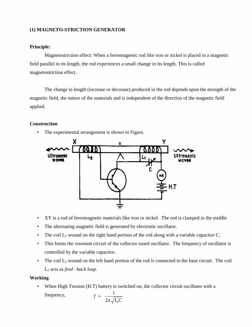
Construction
• The experimental arrangement is shown in Figure.
• XY is a rod of ferromagnetic materials like iron or nickel. The rod is clamped in the middle
• The alternating magnetic field is generated by electronic oscillator.
• The coil L1 wound on the right hand portion of the rod along with a variable capacitor C.
• This forms the resonant circuit of the collector tuned oscillator. The frequency of oscillator is
controlled by the variable capacitor.
• The coil L2 wound on the left hand portion of the rod is connected to the base circuit. The coil
L2 acts as feed –back loop.
Working
• When High Tension (H.T) battery is switched on, the collector circuit oscillates with a
frequency, CL
f12
1

• This alternating current flowing through the coil L1 produces an alternating magnetic field along
the length of the rod. The result is that the rod starts vibrating due to magnetostrictive effect.
• The frequency of vibration of the rod is given by
where l = length of the rod
Y = Young’s modulus of the rod material and
= density of rod material
• The capacitor C is adjusted so that the frequency of the oscillatory circuit is equal to natural
frequency of the rod and thus resonance takes place.
• Now the rod vibrates longitudinally with maximum amplitude and generates ultrasonic waves of
high frequency from its ends.
Advanatages
• The design of this oscillator is very simple and its production cost is low
• At low ultrasonic frequencies, the large power output can be produced without the risk of
damage of the oscillatory circuit.
Disadvanatges
• It has low upper frequency limit and cannot generate ultrasonic frequency above 3000 kHz (ie.
3MHz).
• The frequency of oscillations depends on temperature.
• There will be losses of energy due to hysteresis and eddy current.
(2) PIEZO ELECTRIC GENERATOR
Principle: Inverse piezo electric effect
• If mechanical pressure is applied to one pair of opposite faces of certain crystals like
quartz, equal and opposite electrical charges appear across its other faces. This effect is
called as piezo-electric effect.
• The converse of piezo electric effect is also true.
Y
lf
2
1
• If an electric field is applied to one pair of faces, the corresponding changes in the
dimensions of the other pair of faces of the crystal are produced. This effect is known as
inverse piezo electric effect.
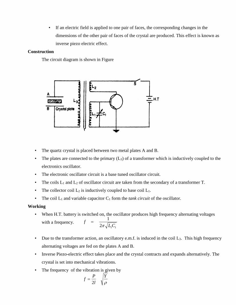
Construction
The circuit diagram is shown in Figure
• The quartz crystal is placed between two metal plates A and B.
• The plates are connected to the primary (L3) of a transformer which is inductively coupled to the
electronics oscillator.
• The electronic oscillator circuit is a base tuned oscillator circuit.
• The coils L1 and L2 of oscillator circuit are taken from the secondary of a transformer T.
• The collector coil L2 is inductively coupled to base coil L1.
• The coil L1 and variable capacitor C1 form the tank circuit of the oscillator.
Working
• When H.T. battery is switched on, the oscillator produces high frequency alternating voltages
with a frequency.
• Due to the transformer action, an oscillatory e.m.f. is induced in the coil L3. This high frequency
alternating voltages are fed on the plates A and B.
• Inverse Piezo-electric effect takes place and the crystal contracts and expands alternatively. The
crystal is set into mechanical vibrations.
• The frequency of the vibration is given by
Y
l
Pf
2
112
1
CLf

where P = 1,2,3,4 … etc. for fundamental, first over tone, second over tone etc.,
Y = Young’s modulus of the crystal and
ρ = density of the crystal.
• The variable condenser C1 is adjusted such that the frequency of the applied AC voltage is equal
to the natural frequency of the quartz crystal, and thus resonance takes place.
• The vibrating crystal produces longitudinal ultrasonic waves of large amplitude.
Advantages
• Ultrasonic frequencies as high as 5 x 10⁸Hz or 500 MHz can be obtained with this arrangement.
• The output of this oscillator is very high.
• It is not affected by temperature and humidity.
Disadvantages
• The cost of piezo electric quartz is very high
• The cutting and shaping of quartz crystal are very complex.
ACOUSTING GRATING
Principle:
When ultrasonic waves are passed through a liquid, the density of the liquid varies layer by layer
due to the variation in pressure and hence the liquid will act as a diffraction grating, so called
acoustic grating.
Under this condition, when a monochromatic source of light is passed through the acoustical
grating, the light gets diffracted. Then, by using the condition for diffraction, the velocity of
ultrasonic waves can be determined.
Construction & Working:
The liquid is taken in a glass cell. The Piezo-electric crystal is fixed at one side of the wall inside
the cell and ultrasonic waves are generated.
The waves travelling from the crystal get reflected by the reflector placed at the opposite wall.
The reflected waves get superimposed with the incident waves producing longitudinal standing
wave pattern called acoustic grating.
If light from a laser source such as He-Ne or diode laser is allowed to pass through the liquid in a
direction perpendicular to the grating, diffraction takes place and one can observe the higher
order diffraction patterns on the screen.
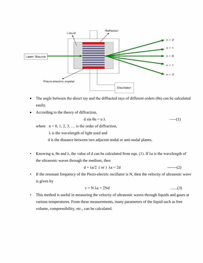
The angle between the direct ray and the diffracted rays of different orders (θn) can be calculated
easily.
According to the theory of diffraction,
d sin θn = n λ -----(1)
where n = 0, 1, 2, 3, … is the order of diffraction,
λ is the wavelength of light used and
d is the distance between two adjacent nodal or anti-nodal planes.
• Knowing n, θn and λ, the value of d can be calculated from eqn. (1). If λa is the wavelength of
the ultrasonic waves through the medium, then
d = λa/2 ( or ) λa = 2d -------(2)
• If the resonant frequency of the Piezo-electric oscillator is N, then the velocity of ultrasonic wave
is given by
v = N λa = 2Nd .......(3)
• This method is useful in measuring the velocity of ultrasonic waves through liquids and gases at
various temperatures. From these measurements, many parameters of the liquid such as free
volume, compressibility, etc., can be calculated.
NON DESTRUCTIVE TESTING
What is NDT?
Nondestructive testing is a method of finding defects in an object without harming the object.
Most Common NDT Methods
Visual Inspection Method
Liquid Penetrant Method
Magnetic Particle Inspection
Ultrasonic Flaw Detection
Eddy Current Testing
X-Ray Diffraction Method
How is ultrasound used in NDT?
Sound with high frequencies, or ultrasound, is one method used in NDT.
Ultrasonic waves are used to detect the presence of flaws or defects in the form of cracks,
blowholes, porosity etc., in the internal structure of a material.
Basically, ultrasonic waves are emitted from a transducer into an object and the returning waves
are analyzed. If an impurity or a crack is present, the sound will bounce off of them and be seen
in the returned signal.
There are two methods of receiving the ultrasound waveform:
(i) attenuation (or through-transmission) and
(ii) reflection (or pulse-echo) mode
THROUGH TRANSMISSION METHOD
Through transmission was used in the early days of ultrasonic testing and is still used in plate
and bar production.
In attenuation (or through-transmission) mode, a transmitter sends ultrasound through one
surface, and a separate receiver detects the amount that has reached it on another surface after
traveling through the medium. Imperfections or other conditions in the space between the
transmitter and receiver reduce the amount of sound transmitted, thus revealing their presence.
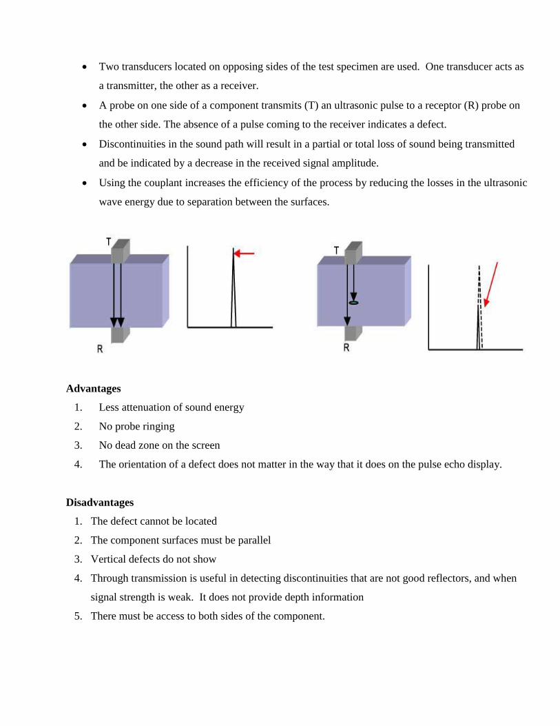
Two transducers located on opposing sides of the test specimen are used. One transducer acts as
a transmitter, the other as a receiver.
A probe on one side of a component transmits (T) an ultrasonic pulse to a receptor (R) probe on
the other side. The absence of a pulse coming to the receiver indicates a defect.
Discontinuities in the sound path will result in a partial or total loss of sound being transmitted
and be indicated by a decrease in the received signal amplitude.
Using the couplant increases the efficiency of the process by reducing the losses in the ultrasonic
wave energy due to separation between the surfaces.
Advantages
1. Less attenuation of sound energy
2. No probe ringing
3. No dead zone on the screen
4. The orientation of a defect does not matter in the way that it does on the pulse echo display.
Disadvantages
1. The defect cannot be located
2. The component surfaces must be parallel
3. Vertical defects do not show
4. Through transmission is useful in detecting discontinuities that are not good reflectors, and when
signal strength is weak. It does not provide depth information
5. There must be access to both sides of the component.
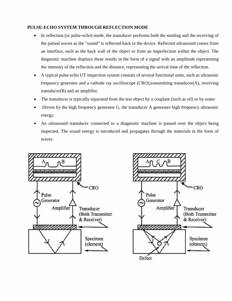
PULSE-ECHO SYSTEM THROUGH REFLECTION MODE
In reflection (or pulse-echo) mode, the transducer performs both the sending and the receiving of
the pulsed waves as the "sound" is reflected back to the device. Reflected ultrasound comes from
an interface, such as the back wall of the object or from an imperfection within the object. The
diagnostic machine displays these results in the form of a signal with an amplitude representing
the intensity of the reflection and the distance, representing the arrival time of the reflection.
A typical pulse-echo UT inspection system consists of several functional units, such as ultrasonic
frequency generator and a cathode ray oscilloscope (CRO),transmitting transducer(A), receiving
transducer(B) and an amplifier.
The transducer is typically separated from the test object by a couplant (such as oil) or by water
Driven by the high frequency generator G, the transducer A generates high frequency ultrasonic
energy.
An ultrasound transducer connected to a diagnostic machine is passed over the object being
inspected. The sound energy is introduced and propagates through the materials in the form of
waves.

When there is a discontinuity (such as a crack) in the wave path, part of the energy will be
reflected back from the flaw surface.
The reflected wave signal is transformed into an electrical signal by the transducer B and is
displayed on a screen.
Knowing the velocity of the waves, travel time can be directly related to the distance that the
signal traveled. From the signal, information about the reflector location, size, orientation and
other features can sometimes be gained.
Advantages
1. High penetrating power, which allows the detection of flaws deep in the part.
2. High sensitivity, permitting the detection of extremely small flaws.
3. Only one surface needs to be accessible.
4. Greater accuracy than other nondestructive methods in determining the depth of internal flaws
and the thickness of parts with parallel surfaces.
5. Some capability of estimating the size, orientation, shape and nature of defects.
6. Non hazardous to operations or to nearby personnel and has no effect on equipment and
materials in the vicinity.
7. Capable of portable or highly automated operation.
Disadvantages
1. Manual operation requires careful attention by experienced technicians.
2. Extensive technical knowledge is required for the development of inspection procedures.
3. Parts those are rough, irregular in shape, very small or thin, or not homogeneous are difficult to
inspect.
4. Surface must be prepared by cleaning and removing loose scale, paint, etc., although paint that is
properly bonded to a surface need not be removed.
5. Couplants are needed to provide effective transfer of ultrasonic wave energy between transducers
and parts being inspected unless a non-contact technique is used. Non-contact techniques include
Laser and Electro Magnetic Acoustic Transducers (EMAT).
6. Inspected items must be water resistant, when using water based couplants that do not contain
rust inhibitors.
MODE OF DISPLAYS
Ultrasonic data can be collected and displayed in a number of different formats. The three most
common formats are known in the NDT world as
A-scan
B-scan and
C-scan presentations.
Each presentation mode provides a different way of looking at and evaluating the region of
material being inspected. Modern computerized ultrasonic scanning systems can display data in
all three presentation forms simultaneously.
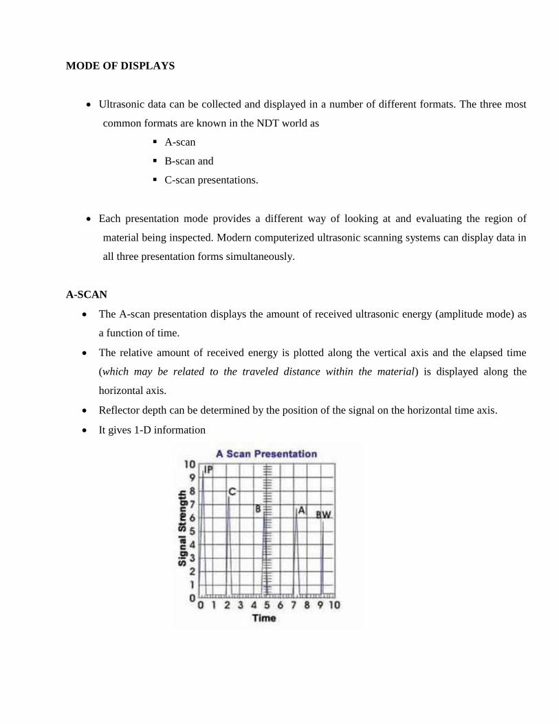
A-SCAN
The A-scan presentation displays the amount of received ultrasonic energy (amplitude mode) as
a function of time.
The relative amount of received energy is plotted along the vertical axis and the elapsed time
(which may be related to the traveled distance within the material) is displayed along the
horizontal axis.
Reflector depth can be determined by the position of the signal on the horizontal time axis.
It gives 1-D information
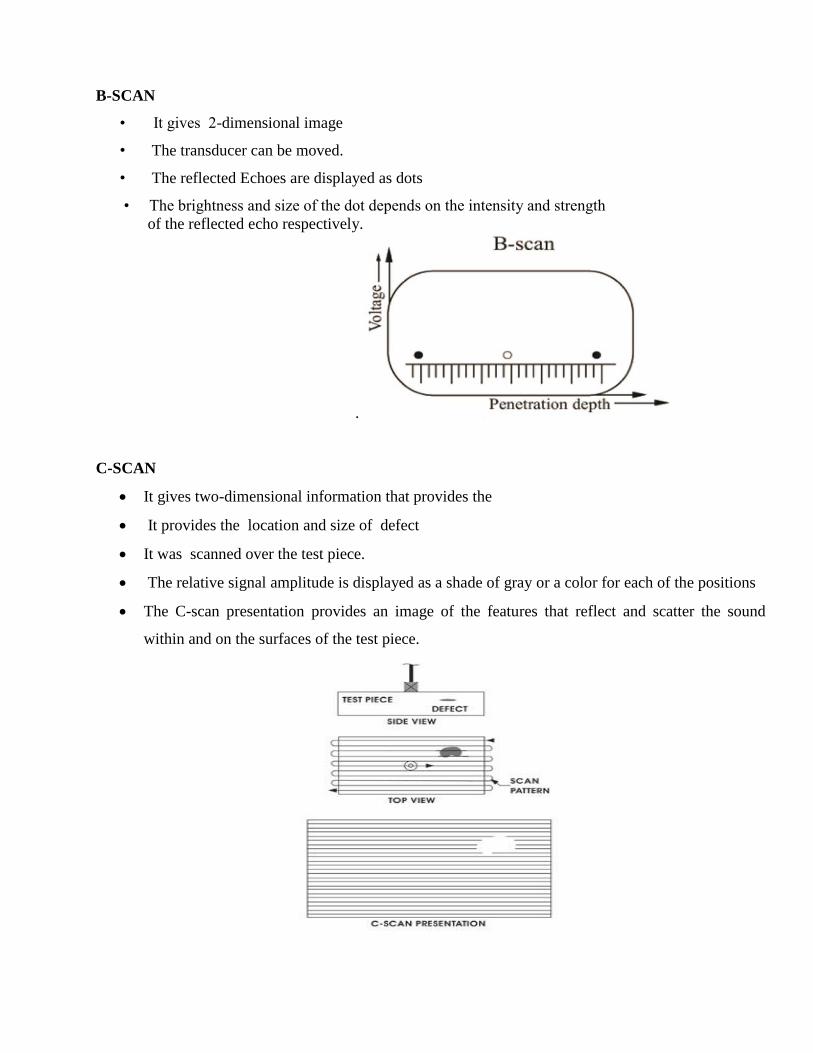
B-SCAN
• It gives 2-dimensional image
• The transducer can be moved.
• The reflected Echoes are displayed as dots
• The brightness and size of the dot depends on the intensity and strength
of the reflected echo respectively.
.
C-SCAN
It gives two-dimensional information that provides the
It provides the location and size of defect
It was scanned over the test piece.
The relative signal amplitude is displayed as a shade of gray or a color for each of the positions
The C-scan presentation provides an image of the features that reflect and scatter the sound
within and on the surfaces of the test piece.
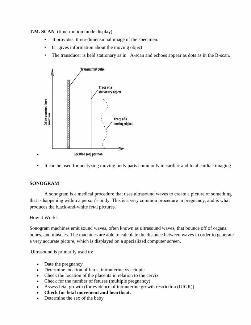
T.M. SCAN (time-motion mode display).
• It provides three-dimensional image of the specimen.
• It gives information about the moving object
• The transducer is held stationary as in A-scan and echoes appear as dots as in the B-scan.
•
• It can be used for analyzing moving body parts commonly in cardiac and fetal cardiac imaging
SONOGRAM
A sonogram is a medical procedure that uses ultrasound waves to create a picture of something
that is happening within a person’s body. This is a very common procedure in pregnancy, and is what
produces the black-and-white fetal pictures.
How it Works
Sonogram machines emit sound waves, often known as ultrasound waves, that bounce off of organs,
bones, and muscles. The machines are able to calculate the distance between waves in order to generate
a very accurate picture, which is displayed on a specialized computer screen.
Ultrasound is primarily used to:
Date the pregnancy
Determine location of fetus, intrauterine vs ectopic
Check the location of the placenta in relation to the cervix
Check for the number of fetuses (multiple pregnancy)
Assess fetal growth (for evidence of intrauterine growth restriction (IUGR))
Check for fetal movement and heartbeat.
Determine the sex of the baby

Fetal movement and heartbeat
Principle : Doppler Effect
When echo falls on the transducer, it generates the electrical pulses and it sent to the ultrasonic
scanner.
There they are processed and transformed into a digital image.
The time taken for the echo to travel back to the probe is measured and used to find the depth of
the tissue interface causing the echo.
If the difference between acoustic impedances is greater and the echo is also larger.
If the pulse falls on the gases or solids the density difference is very high. Most of the acoustic
energy is reflected and it becomes impossible to see deeper.
Image formation
• Time taken to receive the echo is observed.
• Time enables a sharp image and it represents the depth.
• The strength of the echo in the form of pulse represents the movement of objects.

Other Medical Applications of Ultrasonics
Ultrasonics waves are noninvasive medical tool.
• cancer treatment and neurosurgery.
• to clean teeth and also for dental cutting.
• used for cataract treatment .
• A fetus in the womb can be viewed in a sonogram.
• Focused ultrasound may be used to break up kidney stones.
Low-intensity ultrasound has the ability to stimulate bone- growth.
• Ultrasonics guides the blind person who uses ultrasonic guiding stick as a guiding tool