um ct8 - sh-istech.com.cn · version 2009-02 2 technical data are subject to change without notice!...
TRANSCRIPT

Kraus Messtechnik GmbH Gewerbering 9, D-83624 Otterfing, +49-8024-48737, Fax. +49-8024-5532 – Germany Web: www.kmt-gmbh.com Email: [email protected]
CCTT44//88 UUsseerr mmaannuuaall
8-channel telemetry system including signal conditioning for strain gage, thermo
couples, Pt100, ICP, POT and high-level inputs

Version 2009-02 2 Technical Data are subject to change without notice!
General functions:
The CT8 Compact is a 8-channel telemetry system with integrated signal conditioning for sensors, wireless digital transmission and analog reproduction.
The conditioned measured values are routed via anti-aliasing filter to a 12-bit A/D converter, simulate sampling of all channels, encoded in PCM format and transferred to the HF transmitter as modulation variables. Dynamic range is 72dB with a signal-to-noise ratio of approximately 70dB. Four different carrier frequencies available with the 40kbit transmitter ( 433.3 to 434.5 MHz range) and enable a signal bandwidth of 8 x.0-95 Hz. With the 320kbit/s transmitter only one carrier frequency available in the 433,9 MHz band and enable a signal bandwidth of 8 x 0-750 Hz. Various configurations of different sensor modules are possible like signal conditioning for strain gages (STG), thermocouples type K (Th-K), thermo sensors Pt100, ICP sensors, potentiometer sensors (POT) and also Voltage inputs (+/-5 or +/-10V), mixed configuration available.
Frequency table Cut off frequency from anit-aliasing filter (-3dB) and scanning rate (see red)
Bit rate 4 CH. 8 CH.
320 kbit/s 1500 Hz
(6154 Hz)
750 Hz
(3200 Hz)
40 kbit/s 190 Hz
(770 Hz)
95 Hz
(400 Hz)
Picture shows a CT8 telemetry system with standard accessories
DC power cable DC power cable
CT8- encoder
with transmitter
CT4 decoder
with receiver Transmitting
antenna
Receiving
antenna
Specify CT-xx modules at order!!

Version 2009-02 3 Technical Data are subject to change without notice!
Transmitter Device (Encoder)
CT-4/8-ENC
CT-STG V1:
Sensor: strain gage, 350 Ohms
Bridge completion: full, half and quarter-bridge (optional)
Excitation: 4 VDC (fixed), short-circuit protection up to 20mA
Gain: 200 or 1000 - selectable by solder jumpers
Optional Gain: 250-500-1000-2000 with new CT-STG V2 module
Offset Zero adjustment by potentiometer or optional Auto-zero function (which is not lost by power-off), offset range up to 80% of full scale.
CT-TH-K-ISO:
Sensor: thermo-couple, type K ( with cold junction compensation)
Temperature measuring range: -50°C to +1000°C (other on request) with galvanic isolation
CT-PT100:
Sensor: resistance temperature detectors (RTDs) with resistance of 100 ohm
Temperature measuring range: -100°C to +500°C
CT-VOLT:
High-level inputs: +/- 5 Volt or +/- 10 Volt (other ranges on request)
CT-ICP:
Sensor: For ICP® sensor inputs, Current exc. 1, 4, and 10mA
Signal gain x 2, 4, 8, 16, 32 - Signal bandwidth 3 Hz up to 3000Hz (depended of transmitter)
CT-POT:
Sensor: Potentiometer Sensor >350 Ohms to 10kOhm
Excitation: 4 VDC (fixed)
System Parameters:
Channels: 4 or 8
Resolution: 12 bit A/D converter with anti aliasing filter, simultaneous sampling of all channels
Line-of-sight distance: 500 m with 10mW transmitting power (433MHz Band, FSK modulation)
Powering: 10-30V DC
Power consumption: 200 mA (at 12V) using 8 STG sensors at 350 Ohms and 40kbit transmitter
Analog signal bandwidth: (-3dB cut-off frequency)
4-channel version 4 x 0 …190Hz with 40 kbit/s transmitter (433,3, 433.7, 434.1 and 434,5 MHz)
8-channel version 8 x 0 … 95Hz with 40 kbit/s transmitter (433,3, 433.7, 434.1 and 434,5 MHz)
4-channel version 4 x 0 …1500Hz with 320 kbit/s transmitter (1x 433,9 MHz)
8-channel version 8 x 0 … 750Hz with 320 kbit/s transmitter (1x 433,9 MHz)
Dimensions: 132 x 85 x 68mm
Weight: 0.8 kg without cables
Transmission: Digital PCM Miller format - FSK
Transmission Power: 10mW
Operating temperature: - 20 … +70°C
Housing: Aluminum
Humidity: 20 ... 80% no condensing
Static acceleration: 100g in all directions
Shock: 200g in all directions
25-pole female SubD input connector for sensors 1 to 4
7-pole female TUCHEL connector
for power supply input (10–30V DC)
2-pole female LEMOSA connector (for test purposes only) Front side view Rear side view
25-pole female SubD input connector for sensors 5 to 8
Power ON LED
Female BNC connector for transmitter antenna
Power Switch
Auto Zero Switch (option)

Version 2009-02 4 Technical Data are subject to change without notice!
Technical data: Receiving Unit CT4/8 DEC (Decoder)
System Parameters:
Channel: 8 analog outputs via (BNC) +/-5V (optional +/-10V)
Resolution: 12 bit D/A converter, with smoothing filter
Dynamic: 72dB
Power supply input: 10-30 VDC
Current consumption: 300mA at 10V, 100mA at 30V
Analog signal bandwidth: (-3dB cut-off frequency)
4-channel version 4 x 0 …190Hz with 40 kbit/s transmitter (433,3, 433.7, 434.1 and 434,5 MHz)
8-channel version 8 x 0 … 95Hz with 40 kbit/s transmitter (433,3, 433.7, 434.1 and 434,5 MHz)
4-channel version 4 x 0 …1500Hz with 320 kbit/s transmitter (1x 433,9 MHz)
8-channel version 8 x 0 … 750Hz with 320 kbit/s transmitter (1x 433,9 MHz)
Dimensions: 205 x 105 x 65mm
Weight: 1.00 kg without cables and antenna
Overall system accuracy between encoder input and decoder output: +/-0.25% without sensor influences
Environmental
Operating: -20 … +70°C
Humidity: 20 ... 80% not condensing
Vibration: 5g Mil Standard 810C, Curve C
Static acceleration: 10g in all directions
Shock: 100g in all directions
Technical specifications are subject to change without notice!
Sync-Loss Indicator LED
Front view Back view
Field strength indicator
BNC socket for analog
signal outputs 1 … 8
ON/OFF - LED
BNC-socket for receiving antenna
Auto Zero indicator
Ch. 1…8 (Optional)
ON/OFF - switch
7- pole TUCHEL-socket for Voltage supply cable (10–30V)

Version 2009-02 5 Technical Data are subject to change without notice!
Connection STG
CT-STG-V1 module Type: Strain gage >350 Ohms Excitation: 4 VDC (fixed) Gain: 200 or 1000 by solder bridge Accuracy +/- 0.25%
CT-STG-V2 module Type: Strain gage >350 Ohms Excitation: 4 VDC (fixed) Gain: 250-500-1000 or 2000 by jumper or on request 1000-2000-4000-8000 Accuracy +/- 0.25%
Offset potentiometers Channel numbers
Gain setting 200 or 1000 by solder bridge
Offset potentiometers
Gain 200 Gain 1000

Version 2009-02 6 Technical Data are subject to change without notice!
Connection STG - Bridge
Version 2009-02 7 Technical Data are subject to change without notice!
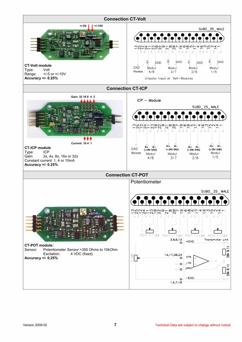
Connection CT-Volt
CT-Volt module Type: Volt Range: +/-5 or +/-10V Accuracy +/- 0.25%
Connection CT-ICP
CT-ICP module Type: ICP Gain: 2x, 4x, 8x, 16x or 32x Constant current: 1, 4 or 10mA Accuracy +/- 0.25%
Connection CT-POT
CT-POT module:
Sensor: Potentiometer Sensor >350 Ohms to 10kOhm Excitation: 4 VDC (fixed) Accuracy +/- 0.25%
Potentiometer
+/-5V +/-10V
Current: 10 4 1
Gain: 32 16 8 4 2

Version 2009-02 8 Technical Data are subject to change without notice!
Connection CT-Pt100
CT-Pt100
Type: RTD 100 ohm Range: -100 to 500°C Accuracy +/- 0.25%
Temperature [°C]
Output [V]
Temperature [°C]
Output [V]
Temperature [°C]
Output [V]
-100 -0,997 150 1,500 400 4,004
-50 -0,497 200 2,001 450 4,498
0 0,001 250 2,501 500 4,999
50 0,499 300 3,001
100 1,000 350 3,501
Connection CT-TH-K-ISO (with galvanic isolation!)
Thermo couple Type: K Range: -50°C – 1000°C Bandwidth: 0-20Hz (more on request) Accuracy +/- 1%
Temperature [°C]
Output [V]
Temperature [°C]
Output [V]
Temperature [°C]
Output [V]
Temperature [°C]
Output [V]
-50 -0.220 250 1.236 550 2.754 850 4.262
0 0.013 300 1.482 600 3.010 900 4.506
50 0.254 350 1.734 650 3.266 950 4.746
100 0.504 400 1.990 700 3.519 1000 4.980
150 0.752 450 2.242 750 3.700
200 0.992 500 2.498 800 4.015
With option +/-10V output you must multiply the table value with *2

Version 2009-02 9 Technical Data are subject to change without notice!
How to change CT Modules at the CT4/8-ENC
1. Open this 4 screws
2. Open this 2 screws
3. Move the right part to right
4. Than you can take out the modules and change to other.
5. Assembly in reverse order!
Work with care!