umaa135 - armas
TRANSCRIPT
*FM 23-25
i

ii

FM 23-25
PREFACE
This manual provides technical information, training techniques, and combattechniques of light antiarmor weapons. Intended users include leaders anddesignated soldiers who will use this information to successfully integrate lightantiarmor weapons into combat operations. This manual discusses gunnery trainingand train-the-trainer.
The tactical positions shown in this manual were drawn to enhance the reader’sunderstanding of related subject material and do not necessarily represent the bestemployment option for that material.
Unless this publication states otherwise, masculine nouns and pronouns do not referexclusively to men.
The proponent of this publication is the United States Army Infantry School. Sendcomments and recommendations on DA Form 2028 (Recommended Changes toPublications and Blank Forms) directly to Commandant, US Army Infantry School,ATTN: ATSH-INB-O, Fort Benning, GA 31905-5595.
iii

CHAPTER 1
INTRODUCTION
This chapter provides information common to the light antiarmor weaponsdiscussed in this manual. Topics include care and handling, destruction anddecontamination procedures, and operating temperatures. Light antiarmorweapons are used against light armored vehicles, field fortifications, or othersimilar targets. These weapons are issued as rounds of ammunition toindividual soldiers in addition to their assigned weapons and the unit’s organicantiarmor weapons. Light antiarmor weapons can withstand extreme weatherand environmental conditions, including arctic, tropical, and desert. The lightantiarmor weapons category includes both light antiarmor and light antitankweapons.
1-1. TYPES OF LIGHT ANTIARMOR WEAPONSLight antiarmor weapons include the M72-series light antitank weapon (LAW) andthe M136 AT4. The M72-series LAW was designed in the early 1960’s for useagainst light tanks of that era (Figure l-l). The M136 AT4 was designed in the late1980’s for use against the improved armor of light armored vehicles (Figure 1-2).
FM 23-25
1-1
FM 23-25
1-2. CARE AND HANDLINGLight antiarmor weapons are issued as rounds of ammunition. The only requirementfor their care is a visual inspection, outlined in the appropriate chapter for eachweapon (Chapter 2 for the LAW and Chapter 3 for the AT4).
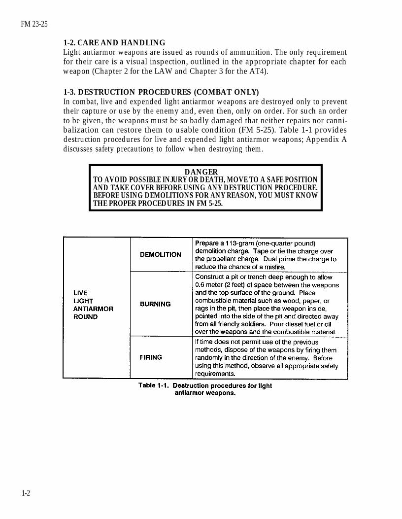
1-3. DESTRUCTION PROCEDURES (COMBAT ONLY)In combat, live and expended light antiarmor weapons are destroyed only to preventtheir capture or use by the enemy and, even then, only on order. For such an orderto be given, the weapons must be so badly damaged that neither repairs nor canni-balization can restore them to usable condition (FM 5-25). Table 1-1 providesdestruction procedures for live and expended light antiarmor weapons; Appendix Adiscusses safety precautions to follow when destroying them.
DANGERTO AVOID POSSIBLE INJURY OR DEATH, MOVE TO A SAFE POSITIONAND TAKE COVER BEFORE USING ANY DESTRUCTION PROCEDURE.BEFORE USING DEMOLITIONS FOR ANY REASON, YOU MUST KNOWTHE PROPER PROCEDURES IN FM 5-25.
1-2

FM 23-25
DANGERWHEN USING FIRE TO DESTROY A LIGHT ANTIARMOR WEAPON, THETIME REQUIRED TO EXPLODE THE WARHEAD IS UNPREDICTABLE.ALSO, IGNITING THE PROPELLANT CAN CAUSE IT TO FIRE THE WAR-HEAD IN ANY DIRECTION, WHICH COULD IN TURN CAUSE INJURYOR DEATH.
OBSERVE THE APPROPRIATE SAFETY PRECAUTIONS WHEN HAN-DLING DIESEL FUEL. CARELESSNESS COULD CAUSE PAINFUL, EVENFATAL, BURNS.
DO NOT TRY TO USE VEHICLES OR MECHANICAL MEANS TO DE-STROY LIVE ANTIARMOR WEAPONS. EITHER METHOD COULD DETO-NATE THE WARHEAD OR PROPELLANT CHARGE, WHICH COULDCAUSE INJURY OR DEATH.
1-4. DECONTAMINATION PROCEDURESThe soldier can use his M258A1 or DKIE (XM280) individual decontaminationpacket to remove H-series, G-series, and V-series agents. FM 3-5 provides more in-formation about decontamination procedures for equipment and weapons.
DANGERNEVER USE DS2 TO DECONTAMINATE ANY LIGHT ANTIARMORWEAPON. THE DS2 WOULD DISSOLVE THE RUBBER AND PLASTICSEALS, ALLOWING THE DS2 TO REACH THE PROPELLANT AND PRO-DUCING AN EXTREMELY HAZARDOUS MIXTURE.
1-3

FM 23-25
1-5. OPERATING TEMPERATURESOperating temperatures for the M72-series LAW and the M136 AT4 are -40° to140°F (-40° to 60°C). Firing light antiarmor weapons in temperatures outsidethese limits could cause a misfire or produce some other hazard for the soldier(Appendix A).
1-4

FM 23-25
CHAPTER 2
M72-SERIES LAW, OPERATION AND FUNCTION
This chapter provides information on and technical data for the M72-serieslight antitank weapon (LAW). It also discusses the characteristics,nomenclature, functioning, and operation of the LAW.
2-1. DESCRIPTIONThe M72-series LAW is a lightweight, self-contained, antiarmor weapon consisting ofa rocket packed in a launcher (Figure 2-1, page 2-2). It is man-portable, may be firedfrom either shoulder, and is issued as a round of ammunition. It requires little fromthe user-only a visual inspection and some operator maintenance. The launcher,which consists of two tubes, one inside the other, serves as a watertight packing con-tainer for the rocket and houses a percussion-type firing mechanism that activatesthe rocket.
a. Outer Tube. The trigger housing assembly (which contains the triggerassembly) is on the upper surface of the outer tube. So are the trigger arminghandle, front and rear sight assemblies, and the launcher’s rear cover.
b. Inner Tube. The inner tube telescopes outward toward the rear, guided by achannel assembly that rides in an alignment slot in the outer tube’s trigger housingassembly. The channel assembly also houses the firing pin rod assembly, whichincludes a detent lever assembly. The detent lever assembly moves under the triggerassembly in the outer tube, locking the inner tube in the extended position andcocking the weapon. All this must occur before the weapon can be fired.
c. Rocket. The rocket is a percussion-ignited, fin-stabilized, fixed munition. It isattached by the igniter to the inside of the launcher. The rocket consists of a 66-mmHEAT warhead, a point-initiating, base-detonating fuze, and a rocket motor. Sixspring-loaded fins are attached to the rear of the rocket motor. These fins are foldedforward along the motor when the rocket is in the launcher. When ignited, thepropellant in the(760ºC). The gasof the launcher as
rocket motor burns completely, producing gasses about 1,400°Fpressure pushes the rocket toward the target and exits to the rearthe backblast.
2-1

FM 23-25
2-2. TECHNICAL DATAThe following data apply to the M72A2 and M72A3 LAWs:
a.
b.
Launcher.Length (Extended). . . . . . . . . . . . . . . . Less than 1 meter (34.67 inches)Length (Closed). . . . . . . . . . . . . . . . . . . 0.67 meters (24.8 inches)Weight (Complete M72A2). . . . . . . . 2.3 kg (5.1 pounds)Weight (Complete M72A3) . . . . . . . . . 2.5 kg (5.5 pounds)Firing Mechanism. . . . . . . . . . . . . . . . PercussionFront Sight. . . . . . . . . . . . . . . . . . . . . . . . . . . Reticle graduated in 25-meter range increments
Weight. . . . . . . . . . . . . . . . . . . . . . . . . . . . . . . .. . . . . .. 144.8 mps (475 fps)10 meters (33 feet)10 meters (33 feet)1,000 meters (3,300 feet)
Rear Sight. . . . . . . . . . . . . . . . . . . . . . . . . . . . Peep sight adjusts automatically to temperature changeRocket.Caliber . . . . . . . . . . . . . . . . . . . . . . . . . . . . . . . . . . . 66 mmLength. . . . . . . . . . . . . . . . . . . . . . . . . . . . . . . . . . 50.8 cm (20 inches)
1.8 kg (2.2 pounds)Muzzle Velocity . . . . . . . . . . . . . . . . . . . . . . . . . . . . . . .Minimum Range (Combat) . . . . . . . . . . . . . . . .Minimum Arming Range . . . . . . . . . . . . . . . . . . . . .Maximum Range . . . . . . . . . . . . . . . . . . . . . . . . . . . . . . . .
Maximum Effective RangesStationary Target. . . . . . . . . . . . . . . . 200 meters (660 feet)
165 meters (541 feet)(Beyond these ranges, there is less than a fifty percentchance of hitting the target.)
Moving Target. . . . . . . . . . . . . . . . . .
2-2

FM 23-25
2-3. AMMUNITIONThe M72-series LAW is issued as a round of ammunition. It contains a nonadjust-able propelling charge and a rocket. Every M72-series LAW has an integralhigh-explosive antitank (HEAT) warhead. The warhead is in the rocket’s head (orbody) section. The fuze and booster are in the rocket’s closure section. The propel-lant, its igniter, and the fin assembly are in the rocket’s motor. No inert versions areavailable (Figure 2-2). Appendix B provides information about appropriate gunnerytraining devices and ammunition. Although the M72-series LAW is mainly used asan antiarmor weapon, it may be used with limited success against secondary targetssuch as gun emplacements, pillboxes, buildings, or light vehicles. (Chapter 6 providesmore information about combat techniques.)
a. Description. The 66-mm HEAT rocket warhead consists of a tapered,thin-gauge steel body. When it explodes, the force and heat of the explosive focusinto a small but powerful gas jet. This directional jet penetrates the target and, if thetarget is a vehicle, sprays molten metal inside. If the jet hits an engine orammunition, it may start a fire or cause an explosion. Figure 2-3 shows how thewarhead penetrates 300 millimeters of rolled homogeneous steel armor.
(1) Impact. The nose cone crushes; the impact sensor activates the fuze.(2) Ignition. The ogive crush switch activates the electric detonator. The booster
detonates, initiating the main charge.(3) Penetration. The main charge fires and forces the warhead body liner into a
directional gas jet that penetrates armor plate.(4) After-armor effects (spalling). The projectile fragments and incendiary effects
produce blinding light and destroy the target’s interior.
2-3

FM 23-25
b. Characteristics. The head of the round is olive drab stenciled in yellow. TheM412 fuze is dropsafe and boresafe. Its minimum arming distance is about 33 feet(10 meters). Six stabilizing fins are attached as part of the motor. As the rocketclears the launcher, springs force open the fins, which stabilize the rocket in flight.
c. Packaging. Five complete M72-series LAWS are packaged within a fiberboardinner pack for a total weight of 12.5 kilograms (27 1/2 pounds). Three inner packsare then placed in a wire-bound wooden box, the gross weight of which is54.5 kilograms (120 pounds) (Figure 2-4).
2-4

FM 23-25
2-4. INSPECTIONBecause the M72-series LAW is issued as a round of ammunition rather than as aweapon, inspection is limited to a visual examination of the sealed unit.
Inspect the launcher’s overall condition before preparing the launcher for use.Check the body for dents, cracks, or bulges.Check the rubber boots covering the trigger bar and barrel detent for tears orpunctures.Ensure the arming handle is present and on SAFE and that the pull pin is inplace.Check the data plate for the phrase, W/COUPLER (Figure 2-5).
DANGERIF THE M72A2 LAW DOES NOT STATE “W/COUPLER” ON ITS DATAPLATE, TURN THE WEAPON INTO THE UNIT AMMUNITION SECTION.
THE COUPLER PREVENTS THE INNER AND OUTER TUBES FROMSEPARATING AND POSSIBLY CAUSING PREMATURE DETONATION.
2-5

FM 23-25
2-5. FIRING MECHANISMThe firing mechanism includes the trigger arming handle, the trigger assembly, andthe firing pin rod assembly (Figure 2-6).
a. Trigger Arming Handle. The trigger arming handle is located forward of thetrigger bar and has two positions: SAFE and ARM. Leave the trigger arming handleon SAFE until the launcher is in the correct firing position (Figure 2-7). To press thetrigger, you must first pull the arming handle forward and lock it in the ARMposition.
b. Trigger Assembly. The trigger assembly is on the top rear of the outer tube.To fire the launcher, press downward on the trigger bar.
c. Firing Pin Rod Assembly. The rear sight cover and the firing pin housing areon the top of the rear of the inner tube. Inside the housing, the primer and the firingpin rod are aligned (Figure 2-8, page 2-8). Pressing the trigger bar releases thetension on the firing pin rod assembly, allowing the firing pin to strike the center ofthe primer.
2-6

FM 23-25
2-7

FM 23-25
2-6. SIGHTSThis paragraph discusses the front and rear sights and their proper use.
a. Front Sight, M72A2 and M72A3 LAWs. The front sight has a raised verticalrange line marked with ranges from 50 to 350 meters in 25-meter increments(Figure 2-9). Two curved stadia lines are etched on the front sights. Do not use thestadia lines on this sight to estimate range, because they are inaccurate. Leadindicators are located on either side of the stadia lines to help you engage movingtargets. On the M72A3, use the front sight illuminated range marks at the 100-meterand 150-meter points to help you engage targets in low light.
WARNINGDO NOT TOUCH THE RANGE MARKS; THEY ARE ILLUMINATED WITH PRO-METHIUM, WHICH IS MILDLY RADIOACTIVE.
2-8

FM 23-25
b. Rear Sight, M72A2 and M72A3 LAWs. Therear sight consists of a steel bracket with a rubberboot and plastic peep sight. This sightautomatically adjusts to changes in temperature(Figure 2-10), which means that its settings areunaffected by temperature.
c. AN/PVS-4 Nightsight. This nightsight isissued with various accessories, including a bracketthat, when mounted on an M72-series LAW, willallow you to use an AN/PVS-4 on the LAW.However, this works only if DS maintenance hasalready installed an M72A1 reticle in theAN/PVS-4. Though the reticle was developed forthe M72A1 LAW, you can also use it with the otherM72-series models. To mount the M72A1 bracketassembly on the LAW—
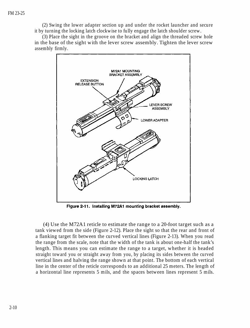
(1) Place the bracket assembly on top of therocket launcher (Figure 2-11) so that the squarecutout in the top of the bracket fits over theextension release button.
2-9
FM 23-25
(2) Swing the lower adapter section up and under the rocket launcher and secureit by turning the locking latch clockwise to fully engage the latch shoulder screw.
(3) Place the sight in the groove on the bracket and align the threaded screw holein the base of the sight with the lever screw assembly. Tighten the lever screwassembly firmly.
(4) Use the M72A1 reticle to estimate the range to a 20-foot target such as atank viewed from the side (Figure 2-12). Place the sight so that the rear and front ofa flanking target fit between the curved vertical lines (Figure 2-13). When you readthe range from the scale, note that the width of the tank is about one-half the tank’slength. This means you can estimate the range to a target, whether it is headedstraight toward you or straight away from you, by placing its sides between the curvedvertical lines and halving the range shown at that point. The bottom of each verticalline in the center of the reticle corresponds to an additional 25 meters. The length ofa horizontal line represents 5 mils, and the spaces between lines represent 5 mils.
2-10

FM 23-25
Use the stadia lines to estimate range only when using the AN/PVS-4’s M72A1reticle pattern.
(5) Align the nightsight’s reticle pattern to the LAW sights only once. After that,you can move the nightsight from LAW to LAW without having to realign it eachtime (Figure 2-14, page 2-12). To align the sight reticle pattern to the LAW sights,place a target at 25 meters. Install the mounting bracket and sight, and select astable firing position for the LAW. Turn both the TUBE BRIGHTNESS andRETICLE BRIGHTNESS knobs ON. Align the 200-meter range mark on thedaysight with the aiming point on the target. Without moving the LAW, adjust thenightsight reticle so that its 200-meter range mark coincides with an aiming point 6.3centimeters left and 3.5 centimeters above-the target aiming point.
- .
DANGERIF YOU CANNOT FIND AN EMPTY LAUNCHER TO USE TO ALIGN THENIGHTSIGHT, YOU MAY USE AN UNFIRED MUNCHER, BUT THIS ISEXTREMELY DANGEROUS.
2-11

FM 23-25
2-7. OPERATION AND FUNCTIONBefore preparing the launcher for use, the firer inspects its overall condition.
a. To extend the rocket launcher—(1) Remove the pull pin and rotate
the rear cover downward so the frontcover and adjustable sling assembly canfall free (Figures 2-15 and 2-16). Donot discard the sling assembly until afteryou fire the rocket.
2-12

FM 23-25
(2) With your firing hand, grasp the rear sight cover; with your nonfiring hand,grasp the launcher forward of the barrel detent. Pull your hands sharply in oppositedirections to extend the launcher (Figure 2-17). To ensure the launcher is fullyextended and locked, try to close it (Figure 2-18, page 2-14).
b. To fire the rocketlauncher, raise it slightlyabove shoulder level, ro-tate your body under it,and place it on yourshoulder. Check the back-blast area, pull the triggerarming handle to theARM position, aim thelauncher, and depress therubber boot on the triggerbar firmly to ensure thelauncher fires (Figure2-19, page 2-14). (If thetrigger arming handle willnot remain in the ARMposition, the launcher isnot fully extended.) Pres-the trigger bar causes thefiring pin to strike theprimer, which ignites theblack powder in the flashtube, which in turn ignitesthe propellant in therocket motor.
2-13

FM 23-25
DANGERWHEN OPERATING THE LAW, KEEP IT POINTED DOWNRANGE. EN-SURE YOUR WHOLE BODY IS CLEAR OF THE MUZZLE AND REAR OFTHE MUNCHER, AND ENSURE THE BACKBLAST AREA IS CLEAR.
2-8. MISFIRE PROCEDURESA misfire is a complete failure to fire caused by a procedural or mechanical failure.Which misfire procedures should be used depends on whether the firer is in a combator training environment.
a. Causes. A misfire is usually caused by one of the following factors:The launcher may not be fully extended.The trigger arming handle may not be armed.The firing mechanism or the propelling charge explosive train may be faulty.
WARNINGKEEP YOUR WEAPON POINTED TOWARD THE TARGET.
b. Combat Environment. If a misfire occurs in combat—(1) Squeeze the trigger again immediately.
2-14

FM 23-25
(2)(3)(4)
fire.(5)
If the launcher still fails to fire, place the trigger arming handle on SAFE.Partly collapse the launcher, then extend it to cock it again.Place it on your shoulder, check the backblast area again, then arm, aim, and
If the LAW still fails to fire, squeeze the trigger again and return the triggerarming handle to SAFE. Collapse the launcher, set it aside, and try another one. Assoon as you can, dispose of the misfired LAW in accordance with SOP.
c. Training Environment. If an M72A2, M72A3, or M190 subcaliber devicemisfires on a live-fire training range—
(1) Squeeze the trigger again.(2) If the launcher still fails to fire, keep the launcher on your shoulder,
announce “Misfire,” and wait 10 seconds. Place the trigger arming handle on SAFE.(3) Move the launcher from your shoulder and wait one minute.(4) Extend the launcher to cock it again, check the backblast area, place the
launcher back on your shoulder, pull the arming handle to the ARM position, aim,and squeeze the trigger bar.
(5) If the launcher again fails to fire, wait 10 seconds before returning the triggerarming handle to the SAFE position.
(6) Keep the launcher trained on the target area at least one minute; DO NOTcollapse the launcher.
(7) Move the launcher to a safe area and dispose of it IAW unit SOP.
2-9. RESTORATION TO CARRYING CONFIGURATIONIf the launcher is prepared to fire, but then is not fired, it should be returned to thecarrying configuration by reversing the preparation procedure. After the launcherhas been prepared for firing, it is no longer watertight. Therefore, when carrying thelauncher, sling it over either shoulder with the muzzle (forward) end down. Only therocket and rocket motor ignition system are waterproof.
a. Return the trigger arming handle to the SAFE position.b. Remove the launcher from your shoulder, depress the barrel detent, collapse
the launcher tube, and guide the front and rear sights into position.c. Close the rear cover, replace the cover pull pin, and replace the sling assembly.
WARNINGTO PREVENT INJURY, REMOVE YOUR THUMB FROM THE DETENT AFTERCOLLAPSING THE LAUNCHER 1/2 TO 1 INCH.
2-15
FM 23-25
CHAPTER 3
M136 AT4, OPERATION AND FUNCTION
This chapter provides information and technical data for the M136 AT4 lightantiarmor weapon, including its characteristics, nomenclature, and operation.Its function, firing mechanism, and safeties are also discussed.
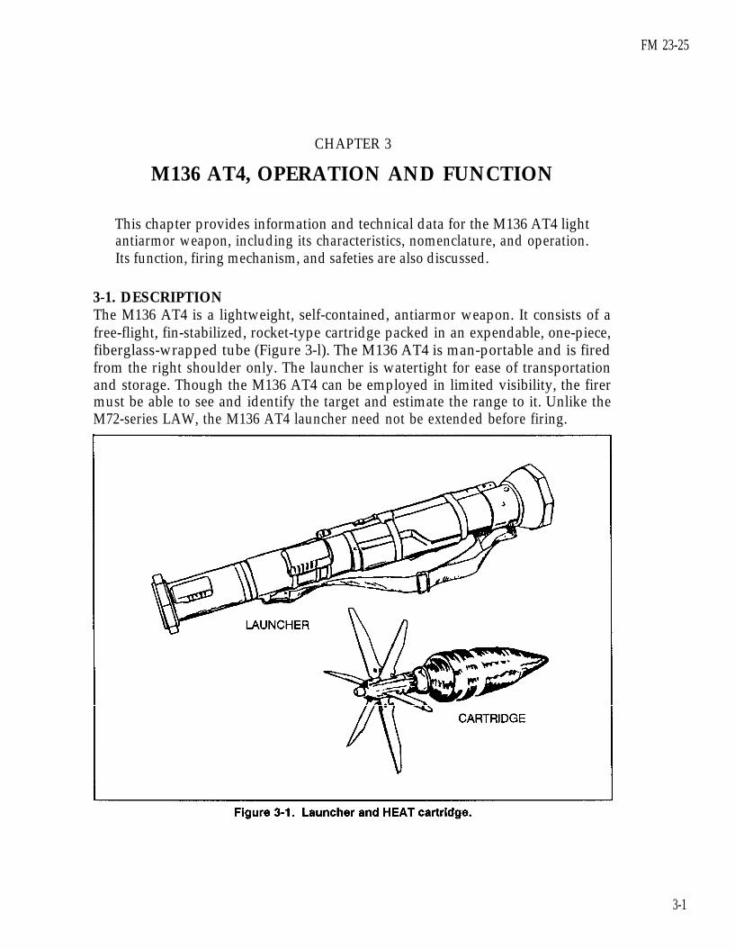
3-1. DESCRIPTIONThe M136 AT4 is a lightweight, self-contained, antiarmor weapon. It consists of afree-flight, fin-stabilized, rocket-type cartridge packed in an expendable, one-piece,fiberglass-wrapped tube (Figure 3-l). The M136 AT4 is man-portable and is firedfrom the right shoulder only. The launcher is watertight for ease of transportationand storage. Though the M136 AT4 can be employed in limited visibility, the firermust be able to see and identify the target and estimate the range to it. Unlike theM72-series LAW, the M136 AT4 launcher need not be extended before firing.
3-1

FM 23-25
3-2. TECHNICAL DATAThe following data apply to the M136 AT4:
a.
b.
Launcher.Length . . . . . . . . . . . . . . . . . . . . . . . . . . . . . . . . . . . . . . . . . . . . . . . . . . 1,020 mm (40 inches)Weight (Complete System) . . . . . . . . . . . . . . . ... 6.7 kg (14.8 pounds)Rear Sight. . . . . . . . . . . . . . . . . . . . . . . . . . . . . . . . . . . . . . . . . . .Range indicator, graduated in 50-meter incrementsRocket.Caliber. . . . . . . . . . . . . . . . . . . . . . . . . . . . . . . . . . . . . . . . . . . . . . . 84 mmMuzzle Velocity. . . . . . . . . . . . . . . . . . . . . . . . . . . . . . . . . 290 mps (950 fps)Length . . . . .. . . . . . . . . . . . . . . . . . . . . . . . . . . . . . . . . . . . . . . . . . . . . 460 mm (18 inches)Weight .. . . . . . . . . . . . . . . . . . . . . . . . . . . . . . . . .. . . . . . . . . . . . . . . .1.8 kg (4 pounds)Minimum Range
Training . . . . . . . . . . . . . . . . . . . . .. . . . . . . . . . . . . . . . . . . .30 meters (100 feet)Combat . . . . . . . . . . . . . . . . . . . . . . . . . . . . . . . . . . . . . . . . . . . . . . . . 10 meters (33 feet)Arming. . . . . . . . . . . . . . . . . .. . . . . . . . . . . . . . . . . . . . . . . 10 meters (33 feet)
Maximum Range . . . . . . . . . . . . . . . . . . . . . . . . . . . . . . . . . . . . 2,100 meters (6,890 feet)Maximum Effective Range . . . . . . . . . . . . . . . . ...300 meters (985 feet)
3-3. AMMUNITIONThe M136 AT4 is a round of ammunition with an integral, rocket-type cartridge. Thecartridge consists of a fin assembly with tracer element; a point-initiating, base-deto-nating, piezoelectric fuze; a warhead body with liner; and a precision-shapedexplosive charge (Figure 3-2).
a. Description. The M136 AT4’s warhead has excellent penetration ability andlethal after-armor effects. The extremely destructive, 440 gram shaped-chargeexplosive penetrates more than 14 inches (35.6 cm) of armor. Warhead effects areshown in Figure 3-3.
(1) Impact. The nose cone crushes; the impact sensor activates the fuze.(2) Ignition. The piezoelectric fuze element activates the electric detonator. The
booster detonates, initiating the main charge.(3) Penetration. The main charge fires and forces the warhead body liner into a
directional gas jet that penetrates armor plate.(4) After-armor effects (spalling). The projectile fragments and incendiary effects
produce blinding light and destroy the interior of the target.
3-2

b. Packaging. Five M136 AT4s, each wrapped in a plastic barrier bag, arepacked together in a wooden container. The containers are too heavy to stack morethan four deep on the pallets (Figure 3-4).
FM 23-25
3-3
FM 23-25
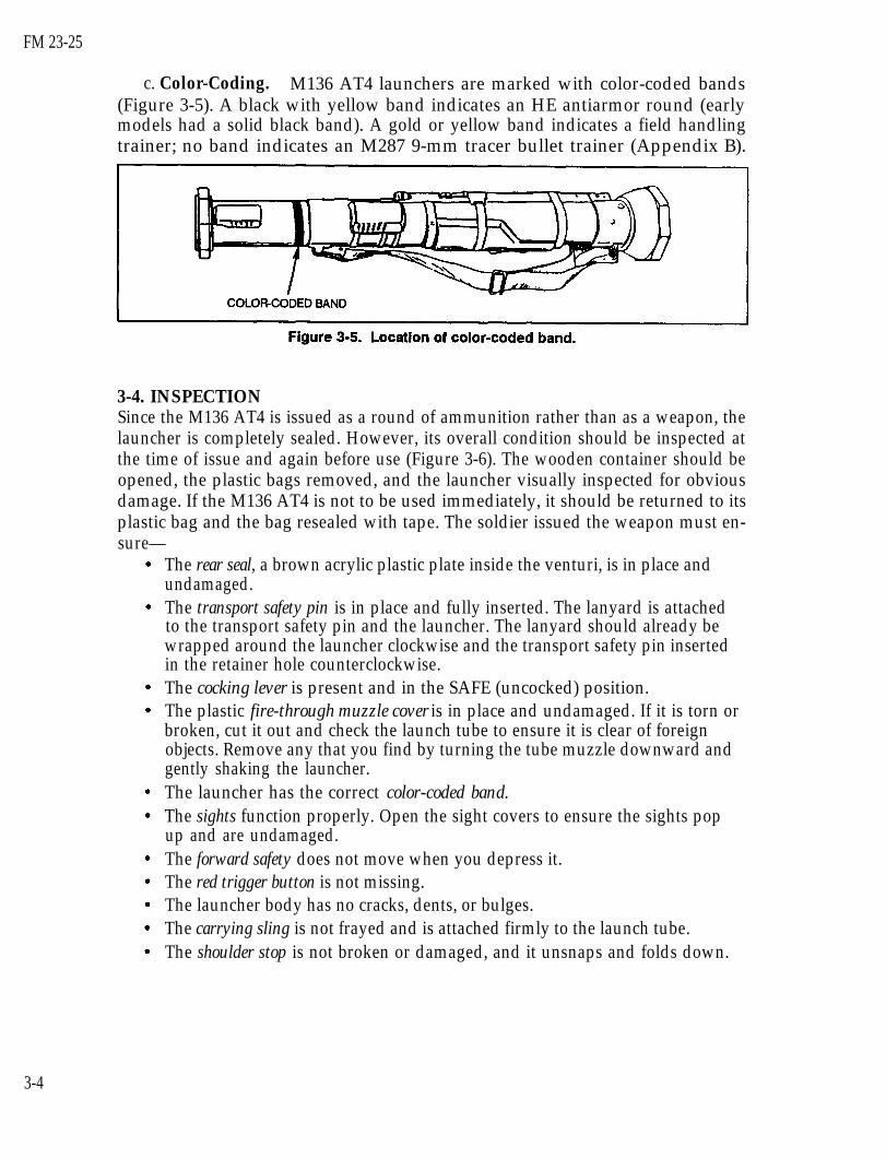
c. Color-Coding. M136 AT4 launchers are marked with color-coded bands(Figure 3-5). A black with yellow band indicates an HE antiarmor round (earlymodels had a solid black band). A gold or yellow band indicates a field handlingtrainer; no band indicates an M287 9-mm tracer bullet trainer (Appendix B).
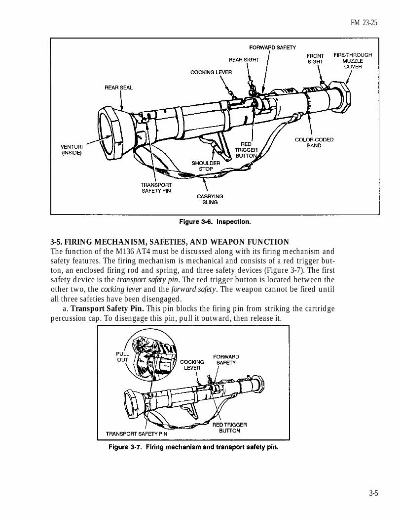
3-4. INSPECTIONSince the M136 AT4 is issued as a round of ammunition rather than as a weapon, thelauncher is completely sealed. However, its overall condition should be inspected atthe time of issue and again before use (Figure 3-6). The wooden container should beopened, the plastic bags removed, and the launcher visually inspected for obviousdamage. If the M136 AT4 is not to be used immediately, it should be returned to itsplastic bag and the bag resealed with tape. The soldier issued the weapon must en-sure—
The rear seal, a brown acrylic plastic plate inside the venturi, is in place andundamaged.The transport safety pin is in place and fully inserted. The lanyard is attachedto the transport safety pin and the launcher. The lanyard should already bewrapped around the launcher clockwise and the transport safety pin insertedin the retainer hole counterclockwise.The cocking lever is present and in the SAFE (uncocked) position.The plastic fire-through muzzle cover is in place and undamaged. If it is torn orbroken, cut it out and check the launch tube to ensure it is clear of foreignobjects. Remove any that you find by turning the tube muzzle downward andgently shaking the launcher.The launcher has the correct color-coded band.The sights function properly. Open the sight covers to ensure the sights popup and are undamaged.The forward safety does not move when you depress it.The red trigger button is not missing.The launcher body has no cracks, dents, or bulges.The carrying sling is not frayed and is attached firmly to the launch tube.The shoulder stop is not broken or damaged, and it unsnaps and folds down.
3-4
FM 23-25
3-5. FIRING MECHANISM, SAFETIES, AND WEAPON FUNCTIONThe function of the M136 AT4 must be discussed along with its firing mechanism andsafety features. The firing mechanism is mechanical and consists of a red trigger but-ton, an enclosed firing rod and spring, and three safety devices (Figure 3-7). The firstsafety device is the transport safety pin. The red trigger button is located between theother two, the cocking lever and the forward safety. The weapon cannot be fired untilall three safeties have been disengaged.
a. Transport Safety Pin. This pin blocks the firing pin from striking the cartridgepercussion cap. To disengage this pin, pull it outward, then release it.
3-5

FM 23-25
b. Cocking Lever. When this lever, which is attached to the firing rod(Figure 3-8), is in the SAFE position, the firing rod and the trigger cannot touch. Tocock the AT4, push the lever forward and down with your right thumb. This causesthe hooks on the front of the firing rod to catch and hold the red trigger button.
c. Forward Safety. This safety is on the front end of the firing mechanism(Figure 3-9) and is connected to a steel rod with a bent end that blocks the firing rodfrom striking the firing pin. To fire the M136 AT4, hold down the forward safety sothe firing rod can strike the percussion cap and ignite the propellant when you pushthe trigger.
3-6

FM 23-25
3-6. SIGHTSThe fact that the AT4’s front and rear sights resemble those of the M16-series riflemakes using the AT4 easier (Figure 3-10).
a. Front Sight. The front sight has a sight blade with a center post and left andright lead posts. A semicircular white line helps you obtain the proper sight picture.To open the front sight cover, press down on it and slide it backward until the sightpops up.
b. Rear Sight. The rear sight has a sight blade, range adjustment knob, rangescale, 2-mm peephole for normal daylight visibility conditions, and 7-mm peepholefor limited visibility conditions. To open the rear sight cover, press down on it andslide it forward until the sight pops up.
c. Nightsight. To find out if a bracket has been approved that would allow use ofa nightsight with the AT4, contact your supply unit or refer to the appropriatetechnical manuals for more current information.
3-7

FM 23-25
(1) The leaf blade that covers the 7-mm peephole has its own tiny 2-mmpeephole. To uncover the 7-mm peephole, pull the bottom of the leaf blade outslightly and rotate it right and up. To cover the 7-mm peephole, rotate it back downand ensure the leaf blade is seated. The range indicator scale is indexed from 100 to500 meters in 50-meter increments.
(2) To increase the range setting beyond 200 meters, turn the range adjustmentknob clockwise, or vice versa (Figure 3-11). You must remember to reset the rangeto 200 meters when you close the rear sight. Otherwise, closing the sight cover willbreak off the rear sight.
3-7. OPERATIONIf you are under fire, take cover before preparing the M136 AT4 for firing as follows:
a. Remove the AT4 from its carrying position and cradle it in your left arm(Figure 3-12).
WARNINGINSERT THE APPROVED BRAND OF EARPLUGS BEFORE YOU FIRE. KEEPTHE WEAPON POINTED TOWARD THE TARGET, AND KEEP THE BACK-BLAST AREA CLEAR.
3-8

FM 23-25
b. With your right hand, pull and release the transport safety pin (Figure 3-13).This pin is important— you must reinsert it if you do not fire the launcher.Therefore, unless it is attached to the launcher with a lanyard, you must keep it in asafe place.
3-9
FM 23-25
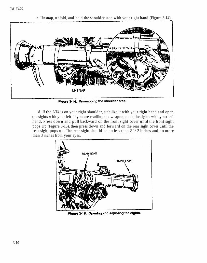
c. Unsnap, unfold, and hold the shoulder stop with your right hand (Figure 3-14).
d. If the AT4 is on your right shoulder, stabilize it with your right hand and openthe sights with your left. If you are cradling the weapon, open the sights with your lefthand. Press down and pull backward on the front sight cover until the front sightpops Up (Figure 3-15), then press down and forward on the rear sight cover until therear sight pops up. The rear sight should be no less than 2 1/2 inches and no morethan 3 inches from your eyes.
3-10

FM 23-25
e. Place the launcher on your right shoulder and stabilize it by grasping the slingnear the launcher’s muzzle with your left hand.
f. Set the rear sight for the correct range to the target.g. Check the backblast area before you cock the launcher. Then, with your right
hand, unfold the cocking lever (Figure 3-16). Place your thumb under it and, with thesupport of your fingers in front of the firing mechanism, push it forward, rotate itdownward and to the right, and let it slide backward.
h. Pull back on the sling with your left hand to seat the shoulder stop firmlyagainst your shoulder. To avoid a misfire, use the index and middle fingers on yourright hand to hold the forward safety down and to the left while you fire (Figure 3-17,page 3-12).
3-8. MISFIRE PROCEDURESA misfire is a complete failure to fire caused by a procedural or mechanical failure.Which misfire procedures should be used depends on whether the firer is in a combator training environment.
a. Causes. A misfire is usually caused by one of the following factors:The forward safety is not depressed far enough to disengage the safety.The firing mechanism is faulty.The propelling charge explosive train is faulty.
3-11

FM 23-25
WARNINGKEEP YOUR WEAPON POINTED TOWARD THE TARGET.
b. Combat Environment. If a misfire occurs in combat—(1)(2)
again.(3)
Release the forward safety.Remove your right hand from the firing mechanism and cock the weapon
Try to fire again. If the launcher still does not fire, maintain the same firingposition and return the cocking lever to the SAFE (uncocked) position.
(4) Move the launcher from your shoulder, keeping the launcher pointed towardthe enemy. Reinsert the transport safety pin.
(5) In combat, break off the sights to identify the misfired launcher. In training,however, you would not want to damage the field handling trainer (FHT), so identifythe misfired launcher simply by leaving the sights up.
(6) Place the launcher on the ground, pointed toward the enemy, and useanother launcher. As soon as you can, dispose of the misfired launcher IAW unitSOP.
3-12

FM 23-25
c. Training Environment. If a misfire occurs on a live-fire training range, thesoldier responds as follows (the trainer later disposes of the launcher IAW localSOP):
(1) Shouts “Misfire” as soon as the launcher fails to fire, while maintaining theoriginal sight picture.
(2) Releases the forward safety.(3) Recocks the launcher: Immediately removes his right hand from the firing
mechanism and pushes the cocking lever forward with the heel of his right hand untilthe lever locks with a loud clicking noise.
NOTE: Because performing immediate action takes so little time, you need notrecheck the backblast area.
(4) Press the forward safety all the way down and try to fire again. If thelauncher still fails to fire, release the forward safety and move the cocking lever tothe SAFE (uncocked) position. Move the launcher from your shoulder, keeping theweapon pointed toward the target.
(5) Reinsert the transport safety pin, wait two minutes, then carefully lay thelauncher on the ground, muzzle toward the target.
NOTE: Notify the local ammunition supply and issue point of any unusualoccurrence, whether the weapon fires or not. Examples include excessiveoverpressure, recoil, or heat on your face after you have fired the weapon(caused by propellant burning after the round leaves the muzzle).
3-9. RESTORATION TO CARRYING CONFIGURATIONIf the launcher is prepared to fire, but then is not fired, it must be taken out of opera-tion as follows:
a. Release the forward safety.b. Push forward and up on the cocking lever, and let it spring back into the SAFE
(uncocked) position.c. Move the launcher from your shoulder, ensuring the muzzle is pointed in the
direction of fire.d. Replace the transport safety pin until it is fully seated in the retainer hole.e. To avoid breaking off the rear sight, remember to reset the range indicator to
the 200-meter setting before closing the rear sight cover.f. Lay down the sights and close their covers.g. Snap the shoulder stop into the closed position.h. Sling the launcher over either shoulder and move to another location.
3-13

FM 23-25
CHAPTER 4
MARKSMANSHIP FUNDAMENTALS
Many factors contribute to light antiarmor weapon marksmanship. Soldierswho combine these factors well and continue to practice doing so can retaintheir skills. The factors are grouped into four basic areas known asmarksmanship fundamentals: steady hold, aiming procedures, breath control,and trigger manipulation. Instructions are given for right-handed firers, butthe M72-series LAW can be fired from either shoulder by simply reversing theinstructions.
4-1. STEADY HOLDMaintaining a steady hold involves holding the launcher as steady as possible whilesighting and firing. To maintain the proper sight picture and sight alignment until hefires, the firer must hold the launcher in a tight, comfortable position so that itbecomes a natural extension of his body (Figure 4-l). With both weapons, keep yourelbows close to your body to help balance the weapon and prevent you from jerkingor flinching when you fire. In the case of the AT4, this reduces recoil.
a. M72-series LAW.launcher near the muzzle
Place your left hand, palm facing upward, under theand grasp the launcher. Firmly pull the rear cover into
your right shoulder pocket.b. M136 AT4. With your left hand, grasp the carrying sling where it attaches to
the launcher near the muzzle. With your right hand on the trigger mechanism, pullthe shoulder stop into your right shoulder pocket.
4-1

FM 23-25
4-2. AIMING PROCEDURESAiming procedures include placing the eye correctly, obtaining a sight picture, andaligning the sight. Combining these procedures is critical to correctly aiming lightantiarmor weapons.
a. Eye Placement. Before sighting the weapon, estimate the range (Chapter 6discusses range estimation). For the M72-series LAW, place your firing eye as closeto the rear sight as is comfortable. However, for the M136 AT4, place your firing eyebetween 2 1/2 to 3 inches (no nearer than 2 1/2 inches) from the rear sight. Thisdistance is necessary to prevent possible injury from the weapon’s recoil and forcorrect sight alignment with the AT4 (Figure 4-2).
WARNINGWHEN FIRING THE M136 AT4, DO NOT PLACE YOUR EYE WITHIN2 1/2 INCHES OF THE REAR SIGHT. THE AT4’S RECOIL COULD CAUSETHE REAR SIGHT TO INJURE YOUR FIRING EYE.
b. Sight Alignment. Align the sights correctly with the target. To do this for theM72-series LAW, position the rear sight so that your eye is near and in line with thepeephole in the rear sight. Look through the peephole at the front sight reticle andplace the range line that corresponds to the target’s range on the target (Figure 4-3).To do this for the AT4, position the rear sight so that the white semicircle of the frontsight is a hazy line around the bottom half of the rear sight opening. Position thefront sight posts on the target (Figure 4-4). Align the sight by moving your headforward or backward.
4-2

FM 23-25
c. Sight Picture. Position the front sight on the target.(1) M72-Series LAW. Stationary targets include those moving directly toward or
away from the firer. Place the correct vertical range line in the center of the target(Figure 4-5). Slow-moving targets include those with an estimated speed of 5 mph-orslower, or those moving in an oblique direction. Place either the left or right leadcross mark on the vehicle’s center of mass (Figure 4-6, page 4-4). Fast-moving targetsinclude those with an estimated speed of more than 5 mph. Place either the left orright lead cross mark on the leading edge of the vehicle (Figure 4-7, page 4-4).
4-3

FM 23-25
(2) M136 AT4. Stationary targets include those moving directly toward or awayfrom the firer. Adjust the rear sight for the correct range and place the center sightpost in the center of the target (Figure 4-8). Slow-moving vehicles are those with anestimated speed of 10 mph or less, or those moving in an oblique direction. Place thecenter sight post on the front or leading edge of the vehicle (Figure 4-9). Fast-movingvehicles are those estimated to be moving faster than 10 mph. Place either the left or
4-4

FM 23-25
right lead post on the center of the target. For example, if the target is moving fromleft to right, place the left lead post on the target’s center of mass, and vice versa(Figure 4-10).
4-5
FM 23-25
4-3. BREATH CONTROLBreath control is as important when firing a light antiarmor weapon as it is when fir-ing an individual weapon. Breathing while firing can cause a miss. To controlbreathing, the firer breathes deeply a couple of times, takes one last deep breath, ex-hales partly, holds his breath, sights, and fires.
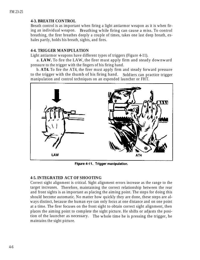
4-4. TRIGGER MANIPULATIONLight antiarmor weapons have different types of triggers (Figure 4-11).
a. LAW. To fire the LAW, the firer must apply firm and steady downwardpressure to the trigger with the fingers of his firing hand.
b. AT4. To fire the AT4, the firer must apply firm and steady forward pressureto the trigger with the thumb of his firing hand. Soldiers can practice triggermanipulation and control techniques on an expended launcher or FHT.
4-5. INTEGRATED ACT OF SHOOTINGCorrect sight alignment is critical. Sight alignment errors increase as the range to thetarget increases. Therefore, maintaining the correct relationship between the rearand front sights is as important as placing the aiming point. The steps for doing thisshould become automatic. No matter how quickly they are done, these steps are al-ways distinct, because the human eye can only focus at one distance and on one pointat a time. The firer focuses on the front sight to obtain correct sight alignment, thenplaces the aiming point to complete the sight picture. He shifts or adjusts the posi-tion of the launcher as necessary. The whole time he is pressing the trigger, hemaintains the sight picture.
4-6

FM 23-25
CHAPTER 5
FIRING POSITIONS
This chapter explains the basic firing positions used with light antiarmorweapons. Instructions for each are given for right-handed firers, but theM72-series LAW can be fired from either shoulder by simply reversing theinstructions. Though each weapon can be fired from all four of the basicfiring positions, individual physique determines exact body and handpositions. Firing from a supported position naturally increases accuracy,which improves the odds for a first-round hit or kill. Basic safetyconsiderations are the same for all light antiarmor weapons, but additionalconsiderations for each firing position are provided here.
5-1. STANDING POSITIONTwo standing positions are used: a basic standing position and one modified for theinfantry fighting position.
a. Basic Standing Position. Raise the launcher slightly higher than shoulderlevel. Execute a left face, rotate your shoulder under the launcher, and spread yourfeet a comfortable distance apart. Move your left foot 15 to 24 inches forward,keeping your hips level and your weight balanced on both feet. To obtain a firm,stable position, tuck both elbows tightly into your body. To track a moving target,turn your body at the waist—not with your legs. This enables you to track the targetsmoothly. Unless you are behind a protective barrier such as a wall, the standingposition exposes you more than any other position to enemy observation andpossible suppression. Differences between weapons with respect to the standingposition are as follows (Figure 5-1, page 5-2):
WARNINGALWAYS KEEP THE LAUNCHER POINTED IN THE DIRECTION OF FIRE.
(1) M72-Series LAW. Place your nonfiring hand about 4 inches from the front ofthe muzzle, with your firing hand on the rear cover. After placing the weapon onyour shoulder, release the rear cover and place your firing hand on the trigger. Cupthe launcher in the palm of your nonfiring hand. Position your firing eye as close tothe rear sight as is comfortable.
(2) M136 AT4. Grasp the sling near the launcher with your left hand and theshoulder stop with your right hand. Raise the launcher above shoulder level. After
5-1

FM 23-25
placing the launcher on your shoulder, release the shoulder stop and place your righthand on the trigger. Place your firing eye 2 1/2 to 3 inches from the rear sight.
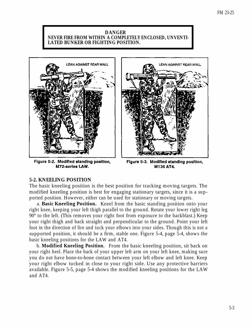
b. Modified Standing Position. Use this position when you occupy an infantryfighting position. Assume the basic standing position, but instead of steppingforward, lean against the back wall of the fighting position. Ensure that the venturior rear of the weapon extends beyond the rear of the fighting position. Figure 5-2shows the modified standing position for the M72-series LAW, Figure 5-3 shows themodified standing position for the M136 AT4. Ensure that NONE of the followingare in your backblast area:
Other soldiers.Other fighting positions.
Equipment.
Any part of your own fighting position.
Obstructions within 5 meters.
NOTE: Leaders must ensure that light antiarmor weapons are positioned so that thebackblast misses other fighting positions.
5-2
FM 23-25
DANGERNEVER FIRE FROM WITHIN A COMPLETELY ENCLOSED, UNVENTI-LATED BUNKER OR FIGHTING POSITION.
5-2. KNEELING POSITIONThe basic kneeling position is the best position for tracking moving targets. Themodified kneeling position is best for engaging stationary targets, since it is a sup-ported position. However, either can be used for stationary or moving targets.
a. Basic Kneeling Position. Kneel from the basic standing position onto yourright knee, keeping your left thigh parallel to the ground. Rotate your lower right leg90° to the left. (This removes your right foot from exposure to the backblast.) Keepyour right thigh and back straight and perpendicular to the ground. Point your leftfoot in the direction of fire and tuck your elbows into your sides. Though this is not asupported position, it should be a firm, stable one. Figure 5-4, page 5-4, shows thebasic kneeling positions for the LAW and AT4.
b. Modified Kneeling Position. From the basic kneeling position, sit back onyour right heel. Place the back of your upper left arm on your left knee, making sureyou do not have bone-to-bone contact between your left elbow and left knee. Keepyour right elbow tucked in close to your right side. Use any protective barriersavailable. Figure 5-5, page 5-4 shows the modified kneeling positions for the LAWand AT4.
5-3

FM 23-25
5-4

5-3. SITTING POSITIONThe sitting position is the most stable firing position. In this position, the arms areplaced on the legs for support. Depending on his physique, the firer can use either oftwo versions of the sitting position. Either is suitable for engaging stationary targets.
a. Basic Sitting Position. Sit on your buttocks while facing the target, and spreadyour feet a comfortable distance apart. Lean forward and place the backs of yourupper arms on your knees, avoiding bone-to-bone contact. Figure 5-6 shows thebasic sitting positions for the LAW and AT4.
b. Modified Sitting Position. From the basic sitting position, cross your anklesfor added support. Raise or lower your knees to adjust for elevation on the target.Figure 5-7 shows the modified sitting positions for the LAW and AT4.
FM 23-25
5-5
FM 23-25
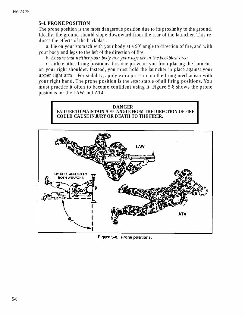
5-4. PRONE POSITIONThe prone position is the most dangerous position due to its proximity to the ground.Ideally, the ground should slope downward from the rear of the launcher. This re-duces the effects of the backblast.
a. Lie on your stomach with your body at a 90° angle to direction of fire, and withyour body and legs to the left of the direction of fire.
b. Ensure that neither your body nor your legs are in the backblast area.c. Unlike other firing positions, this one prevents you from placing the launcher
on your right shoulder. Instead, you must hold the launcher in place against yourupper right arm. For stability, apply extra pressure on the firing mechanism withyour right hand. The prone position is the least stable of all firing positions. Youmust practice it often to become confident using it. Figure 5-8 shows the pronepositions for the LAW and AT4.
DANGERFAILURE TO MAINTAIN A 90° ANGLE FROM THE DIRECTION OF FIRECOULD CAUSE INJURY OR DEATH TO THE FIRER.
5-6

FM 23-25
CHAPTER 6
COMBAT TECHNIQUES
This chapter discusses employment techniques forall of which require at least basic gunnery skills.advanced skills are identified as such.
light antiarmor weapons,Techniques that require
6-1. RANGE ESTIMATIONA firer who can accurately estimate the range to the target has a better chance of hit-ting it, regardless of the weapon used. Common methods of estimating range arelisted below from the most to least accurate. The tactical situation determines themethod to be used:
a. Using range finders.b. Measuring the distance on a map after correctly plotting your own position.c. Pacing. Remember your individual pace count.d. Using pair and sequence methods of target engagement. This method should
be used only when in contact with the enemy.e. Estimating range visually. This is the least accurate method of estimating
range and therefore the least desirable. However, in an offensive operation or hastydefense, it may be the only method available to the light antiarmor firer. Thussoldiers must continually train to improve their skill at visual estimation(STP 21-1-SMCT). Leaders should identify, coordinate, and record ranges topossible armored vehicle engagement locations on squad and platoon sectorsketches.
6-2. SPEED ESTIMATIONOf the weapons discussed in this manual, the M136 AT4 is the best for engagingmoving armored vehicles. One of its advantages over the LAW is the speed of itsround, which travels faster and farther than the LAW round. However, the firer isthe key in any engagement, especially a moving target engagement. Once soldierslearn to estimate speeds at known ranges, they should rehearse until they achieve ahigh hit-to-kill ratio. As their abilities improve, the leaders vary the ranges, speeds,and types of armored vehicles. Figure 6-1, page 6-2, shows one method of speed esti-mation. Trainers and soldiers develop other methods through practice and arelimited only by their imaginations. (Chapter 4 discusses obtaining a sight picture indetail.) Estimate how far the vehicle travels during 1 second:
a. Start when the front end of the vehicle passes the object.
6-1

FM 23-25
b. Count, "One thousand and one'' (takes about one second).c. If more than half of the vehicle passes the object, estimate it as a fast-moving
vehicle (10 mph or faster). If less than half of the vehicle passes the object, estimateit as a slow-moving vehicle (less than 10 mph).
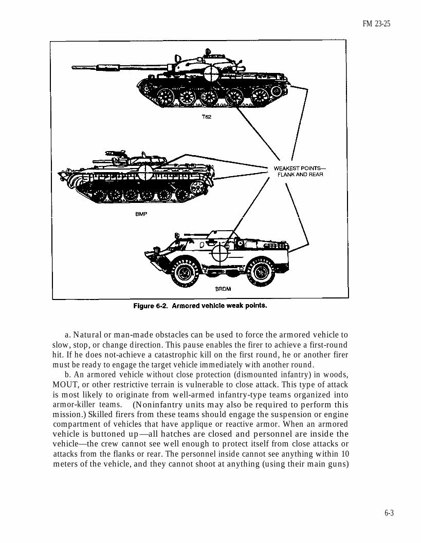
6-3. ARMORED VEHICLE WEAKNESSESArmored vehicles usually have their heaviest armor in front, because they are de-signed mainly for offensive operations against other armored vehicles (Figure 6-2).All vehicles are vulnerable to repeated hits on their flanks and rear, though the flankoffers the largest possible target. Firers should always aim center of mass to increasethe probability of a hit. The older the vehicle model, the less protection it has againstantiarmor weapons. Consequently, newer versions may use bolt-on (applique) armorto improve their survivability. Some vehicles are equipped with reactive armor,which consists of metal plates and plastic explosives. Reactive armor usually coversthe forward-facing portions and sides of the vehicle and can defeat shaped-chargeweapons such as the LAW and AT4. When reactive armor detonates, it dispersesmetal fragments to 200 meters. The M72-series LAW and the M136 AT4 cause onlya small entry hole in an armored vehicle target, though some fragmentation or spanmay occur.
6-2
FM 23-25
a. Natural or man-made obstacles can be used to force the armored vehicle toslow, stop, or change direction. This pause enables the firer to achieve a first-roundhit. If he does not-achieve a catastrophic kill on the first round, he or another firermust be ready to engage the target vehicle immediately with another round.
b. An armored vehicle without close protection (dismounted infantry) in woods,MOUT, or other restrictive terrain is vulnerable to close attack. This type of attackis most likely to originate from well-armed infantry-type teams organized intoarmor-killer teams. (Noninfantry units may also be required to perform thismission.) Skilled firers from these teams should engage the suspension or enginecompartment of vehicles that have applique or reactive armor. When an armoredvehicle is buttoned up—all hatches are closed and personnel are inside thevehicle—the crew cannot see well enough to protect itself from close attacks orattacks from the flanks or rear. The personnel inside cannot see anything within 10meters of the vehicle, and they cannot shoot at anything (using their main guns)
6-3

FM 23-25
within 20 meters. The white area in Figure 6-3 shows the most favorable direction ofattack when the turret is facing to the front; the gray area shows the vehicle’sprincipal direction of fire and observation when the turret is facing to the front.
c. Armored vehicle kills are classified according to the level of damage achieved(Table 6-l).
6-4
FM 23-25
6-4. METHODS OF ENGAGEMENTThe four engagement methods include single, sequence, pair, and volley firing. Theleader evaluates the situation on the ground to determine which of these methods touse. Regardless of whether they are used singly or in combination, communicationsare needed as well. The methods of engagement are rehearsed IAW unit SOP.
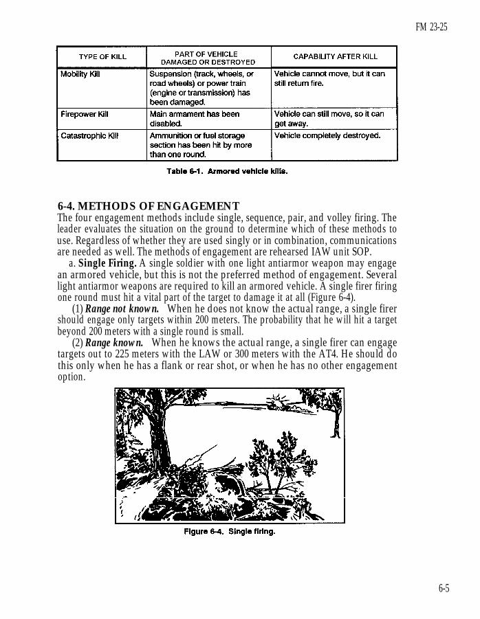
a. Single Firing. A single soldier with one light antiarmor weapon may engagean armored vehicle, but this is not the preferred method of engagement. Severallight antiarmor weapons are required to kill an armored vehicle. A single firer firingone round must hit a vital part of the target to damage it at all (Figure 6-4).
(1) Range not known. When he does not know the actual range, a single firershould engage only targets within 200 meters. The probability that he will hit a targetbeyond 200 meters with a single round is small.
(2) Range known. When he knows the actual range, a single firer can engagetargets out to 225 meters with the LAW or 300 meters with the AT4. He should dothis only when he has a flank or rear shot, or when he has no other engagementoption.
6-5
FM 23-25
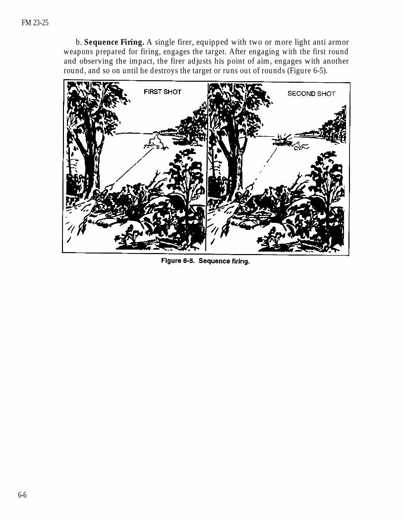
b. Sequence Firing. A single firer, equipped with two or more light anti armorweapons prepared for firing, engages the target. After engaging with the first roundand observing the impact, the firer adjusts his point of aim, engages with anotherround, and so on until he destroys the target or runs out of rounds (Figure 6-5).
6-6

FM 23-25
c. Pair Firing. Two or more firers, equipped with two or more light antiarmorweapons prepared for firing, engage a single target. Before firing, the first firerinforms the others of the estimated speed and distance to the target. If the impact ofhis round proves his estimate to be correct, the other firers engage the target until itis destroyed. If the impact of the round proves his estimate to be incorrect, thesecond firer informs the others of his own estimate, then he engages the target. Thiscontinues until the target is destroyed or all rounds are expended (Figure 6-6).
6-7
FM 23-25
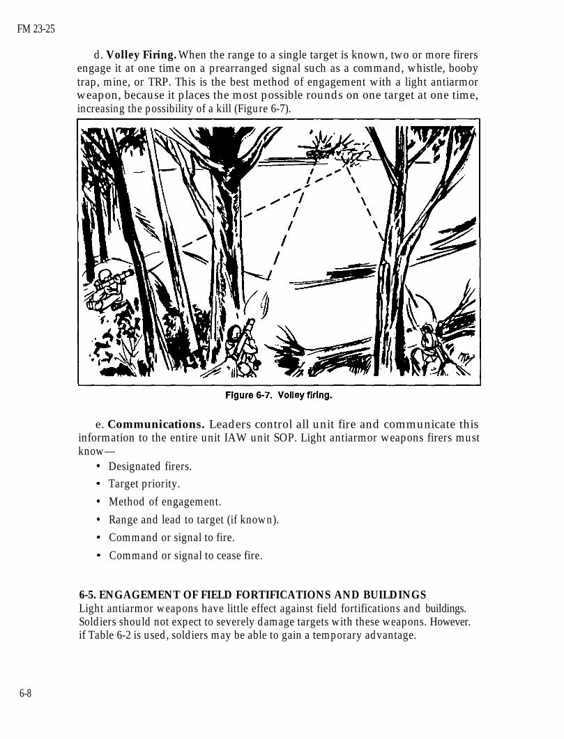
d. Volley Firing. When the range to a single target is known, two or more firersengage it at one time on a prearranged signal such as a command, whistle, boobytrap, mine, or TRP. This is the best method of engagement with a light antiarmorweapon, because it places the most possible rounds on one target at one time,increasing the possibility of a kill (Figure 6-7).
e. Communications. Leaders control all unit fire and communicate thisinformation to the entire unit IAW unit SOP. Light antiarmor weapons firers mustknow—
Designated firers.Target priority.Method of engagement.Range and lead to target (if known).Command or signal to fire.Command or signal to cease fire.
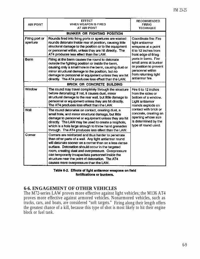
6-5. ENGAGEMENT OF FIELD FORTIFICATIONS AND BUILDINGSLight antiarmor weapons have little effect against field fortifications and buildings.Soldiers should not expect to severely damage targets with these weapons. However.if Table 6-2 is used, soldiers may be able to gain a temporary advantage.
6-8
FM 23-25
6-6. ENGAGEMENT OF OTHER VEHICLESThe M72-series LAW proves more effective against light vehicles; the M136 AT4proves more effective against armored vehicles. Nonarmored vehicles, such astrucks, cars, and boats, are considered “soft targets.” Firing along their length offersthe greatest chance of a kill, because this type of shot is most likely to hit their engineblock or fuel tank.
6-9
FM 23-25
6-7. LIMITED VISIBILITY ENGAGEMENTSLimited visibility engagements can be conducted with an AN/PVS-4 night vision de-vice or with artificial illumination. However, even when NVDs or artificialillumination is used, limited visibility reduces the maximum effective range for lightantiarmor weapons by at least one-third. To avoid fratricide, leaders must ensure alldesignated light antiarmor weapon firers are trained to use their weapons in limitedvisibility.
a. Night Vision Device. Before an AN/PVS-4 can be used with the M72-seriesLAW, it must be removed from its designated weapon (M249 machine gun orautomatic weapon, or M60 machine gun) and sent to DS for installation of theM72A1 reticle. (Chapter 2 provides more information about this device.)
b. Artificial Illumination. If artificial illumination is used during a limitedvisibility engagement, it should be placed above and slightly beyond the target.However, the ability to identify and engage targets is even less with artificialillumination than with NVDs.
6-8. ENGAGEMENT IN NBC CONDITIONSWearing a protective mask limits the firer’s ability to sight the weapon. WearingNBC gloves limits his ability to manipulate the firing mechanism.
a. Sighting the Weapon. Sighting while wearing the protective mask may requirerotating the weapon slightly counterclockwise. The mask also makes determining thelocation, identity, and engageability of targets more difficult.
b. Firing the Weapon. Practice manipulating the firing mechanism while wearingNBC gloves.
NOTE: When live firing either a light antiarmor weapon or its subcaliber trainer, aimwithin range firing limits.
DANGERTHE M136 AT4 IS NOT RATED SAFE. IN TRAINING, NEVER FIRE ITFROM AN ENCLOSURE; IN COMBAT, DO SO ONLY WHEN NO OTHERPOSITION IS AVAILABLE. THE OVERPRESSURE AND BLAST COM-BINED CREATE CONDITIONS THAT CAN KILL YOU. IF THEY DON’TKILL YOU, THEY CAN INJURE YOU SERIOUSLY OR DEAFEN YOU TEM-PORARILY OR PERMANENTLY.
6-9. ENGAGEMENT FROM AN ENCLOSUREFiring from an enclosure creates unique hazards. As such, before positioning sol-diers in enclosures (in combat only), leaders must consider several factors that affectsafety. Only in combat, when no other tactical option exists, should the M136 AT4 befired from an enclosure. If it must be employed this way, the enclosure must meetthe following minimum requirements. The M72-series LAW has been rated as safefor use from an enclosure but, again, only when the enclosure meets the followingminimum requirements:
6-10

a. Construction. The building must be sturdily constructed tostructural damage that would occur in a weakly constructed enclosuremade of wood or stucco.
FM 23-25
reduce thesuch as one
b. Size of Enclosure. Minimum measurements for the building are —
A T 4 - minimum room size 17x 24 feet.LAW - minimum room size 12x 15 feet.Both - minimum ceiling height 8 feet.
c. Ventilation to the Rear and Sides. To allow for the backblast, at least20 square feet of ventilation—such as a standard 3-foot by 7-foot doorway-must beprovided directly behind the firer. More doors and windows must be removed besideand behind the position to increase ventilation and reduce overpressure, noise, andblast effects. Without sufficient ventilation, the blast would weaken or collapse thewalls. On the front wall, windows and doors must be reinforced rather than removed,because removing would draw attention to the position. Reinforcing the windowsalso helps protect the firer from enemy direct-fire weapons.
d. Objects and Debris. All objects and debris must be removed from the rear ofthe weapon, because the backblast will cause them to fly around the room and injurepersonnel.
e. Muzzle Clearance. This must be at least 6 inches.f. Weapon Clearance. Properly positioning the weapons within the enclosure is
vital to the safety and survival of all personnel in the enclosure. The weapons shouldbe positioned so that no walls are within 5 meters to the rear or side of the weapon.
g. Personnel Positions. If any other soldiers must be present, then they mustremain forward of the rear of the launcher and avoid standing in corners or nearwalls. If possible, they should construct reinforced positions that fit the previouscriteria and that can protect them in case the building collapses.
WARNINGTO AVOID INJURING YOUR EARDRUMS, YOU MUST WEAR THE APPROVEDBRAND OF EAR PROTECTION.
6-10. ENGAGEMENT BEYOND MAXIMUM EFFECTIVE RANGE(M136 AT4 ONLY)A skilled M136 AT4 firer can engage targets beyond the weapon’s maximum effec-tive range of 300 meters, up to 550 meters. Beyond 550 meters, the firer must aimhigher than center of mass and apply additional lead for moving targets. Command-ers must realize that accuracy is reduced at these ranges. Also, firing at these rangesidentifies the firing position to the enemy.
6-11

FM 23-25
6-11. OFFENSIVE OPERATIONSAll elements, even those with other organic antiarmor weapons, use light antiarmorweapons. Light antiarmor weapons can influence the action in an attack, so unitsshould routinely stock them beforehand. They are most useful against lightly ar-mored vehicles. They can also be used against soft targets, such as bunkers, fieldfortifications, automobiles, and trucks, but their shaped-charge warheads have lesseffect on these than on armored targets. Unless personnel, ordnance, or flammablematerial on or inside them are hit, soft targets can normally continue to fight afterbeing attacked by light antiarmor weapons. Due to their relatively short range, lightantiarmor weapons should be placed throughout the attacking force. They supportthe maneuver by providing a base of fire, and they enable the assaulting force to en-gage in close antiarmor combat.
6-12. DEFENSIVE OPERATIONSWhether or not other organic antiarmor weapons are available, light antiarmorweapons are an asset in the squad and platoon defensive plan.
a. As is true for other weapons, light antiarmor weapons must be employed withinterlocking fires to provide mutual support. Dispersion allows leaders the flexibilityto place flank, rear, and oblique fires on targets. This increases the survivability ofthe firers as well as their probability of achieving kills. Leaders must select positionsthat avoid fratricide from antiarmor backblast and short rounds (Appendix A).
b. As it does with other key assets, the squad and platoon leader’s sector sketchidentifies TRPs and primary areas of possible engagement. The sector sketch alsoidentifies possible avenues of approach for enemy armored vehicles. Each lightantiarmor weapon shares a sector of fire with the primary small-arms weaponassigned to its position. However, because it is neither a primary nor crew-sewedweapon, the light antiarmor weapon does not require a separate range card. Whenassigning sectors of fire, squad and platoon leaders inform firers of all possible targetareas, TRPs, and prearranged signals (Figure 6-8). (FMs 7-7, 7-7J, and 7-8 providemore information about the squad and platoon sector sketch.) Leaders provide eachdesignated position with two or more light antiarmor weapons.
6-12

FM 23-25
6-13. OTHER TACTICAL OPERATIONSThe weight of the light antiarmor weapon suits it well for combat patrols and reararea operations. (FM 7-8 provides more information about these subjects.)
a. Combat Patrols. Light antiarmor weapons are used on combat patrols todestroy enemy equipment, installations, and key points, and to harass enemy forces.The two types of combat patrols are—
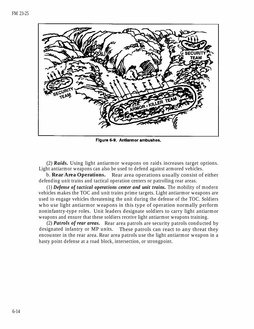
(1) Ambushes (antiarmor). The commander may employ armor-killer teamseither during limited visibility or when cover, concealment, and withdrawal routes areavailable. The key to ambushing armored or other vehicles is to choose terrain thatrestricts their maneuverability and fields of fire, but that allows friendly forces toengage the vehicles from the flank and rear. Soldiers can emplace antipersonnelmines before the ambush so dismounting enemy soldiers will deploy into them.Though light antiarmor weapons may be used independently, they are normally usedin support of designated organic antiarmor weapons such as the Dragon. Volleyfiring light antiarmor weapons increases the probability of a quick kill (Figure 6-9,page 6-14). Security teams stop the enemy from escaping.
6-13
FM 23-25
(2) Raids. Using light antiarmor weapons on raids increases target options.Light antiarmor weapons can also be used to defend against armored vehicles.
b. Rear Area Operations. Rear area operations usually consist of eitherdefending unit trains and tactical operation centers or patrolling rear areas.
(1) Defense of tactical operations center and unit trains. The mobility of modernvehicles makes the TOC and unit trains prime targets. Light antiarmor weapons areused to engage vehicles threatening the unit during the defense of the TOC. Soldierswho use light antiarmor weapons in this type of operation normally performnoninfantry-type roles. Unit leaders designate soldiers to carry light antiarmorweapons and ensure that these soldiers receive light antiarmor weapons training.
(2) Patrols of rear areas. Rear area patrols are security patrols conducted bydesignated infantry or MP units. These patrols can react to any threat theyencounter in the rear area. Rear area patrols use the light antiarmor weapon in ahasty point defense at a road block, intersection, or strongpoint.
6-14

FM 23-25
CHAPTER 7
TRAIN-THE-TRAINER AND UNIT TRAININGPROGRAMS
During initial-entry training, soldiers receive only an orientation for each ofthe light antiarmor weapons. When they arrive in a unit, soldiers should trainto Skill Level 1 proficiency on all assigned weapons and equipment. Each unitshould have an ongoing unit training program to allow soldiers to worktogether to attain and sustain their skills. This program integrates individualand collective tasks. Operating a unit training program requires the unit toalso maintain a train-the-trainer program. Both programs are planned andconducted IAW the commander’s METL.
7-1. TRAINING STRATEGYTraining strategy integrates resources into a year-round program to train the individ-ual and collective skills needed to perform the wartime mission. Thus, units aretrained to fight and win on the battlefield. The training strategy includes institutionaland unit training.
a. Institutional Training. TRADOC schools conduct institutional training.These courses train critical individual and leader skills required to succeed in combat.Students are provided the latest doctrine and taught current technical skillsassociated with the light antiarmor weapons available within the Army. Soldiers trainat several institutional schools throughout their career (see the appropriate programsof instruction [POIs]) (Table 7-1).
7-1

FM 23-25
b. Unit Training. Unit training consists of initial and sustainment training inindividual and collective skills. Commanders manage their resources (devices,simulators, simulations, ranges, and ammunition) carefully to best develop individualand leader skills. Through the use of exercises, (drills, STXs, and qualificationtables), the unit develops skills and integrates individuals into a cohesive crew orsquad. Table 7-2 provides a training guide for building a light antiarmor weaponssustainment training plan (see also Appendixes C and E).
7-2. UNIT TRAINING PROGRAMEvery unit commander, including those commanding CS and CSS units, should develop aprogram for light antiarmor training. Some units have both types of light antiarmorweapon, so both require sustainment training. The commander considers preparationand training for both collective and individual tasks. Trainers analyze their collectivetasks and the individual tasks that support them. Individual tasks must be integrated intocollective training and rehearsals. The units should try to train both light antiarmorweapons at the same time and on the same range (Appendix D). Otherwise, these weap-ons are trained in alternating quarters of the year.
a. Sustainment Training Requirements. Sustainment training is recommendedfor each soldier. Active Component units should conduct sustainment trainingquarterly and fire the appropriate qualification tables semiannually, depending onthe STRAC TRC level. Reserve Component units should conduct sustainmenttraining semiannually and fire the appropriate instructional or qualification tablesannually. All units should fire advanced instructional tables semiannually. Whenpossible, they should conduct live fire annually IAW the current STRAC manual.(Appendix E provides all the necessary firing tables.) Commanders should ensurethat designated gunners complete unit sustainment training and live fire tactical lightantiarmor weapons sometime during that quarter. Training requirements are divided
7-2

FM 23-25
into four tracks, A through D, based onammunition allocations (Table 7-3).Table 7-4 provides an example trainingfrequency chart. This example is basedon the AT4. The same tasks apply tothe LAW, but procedures and standardsmay vary. Tactical weapons areallocated IAW the current standards intraining commission (STRAC) manual.
b. Gunnery Training Requirements.All designated soldiers should betrained to standard IAW the combattechniques in Chapter 6 and the perfor-mance evaluations in Appendix C.
7-3

FM 23-25
c. Collective Training. Individual tasks must be integrated into collectivetraining and rehearsals. To accomplish this, commanders analyze the collective tasksfrom their unit METL and the individual tasks that support the collective tasks. Thecommander determines which collective tasks must be practiced by analyzing themission outlines in the appropriate mission training plan (MTP). The missionoutlines describe the collective tasks required to execute each ARTEP mission.Leaders determine which individual tasks support the collective tasks by referring tothe collective task-to-individual task matrix in the appropriate MTP.
(1) Leaders use the training standards given in the appropriate manual for theindividual tasks. Noninfantry units can use FMs 7-7, 7-7J, 7-8, 7-10, and 7-20 toidentify infantry-type missions. Some of the tasks identified may include engagingarmored vehicles. When planning training, the trainer incorporates the training
devices and aids for light antiarmorweapons into the unit’s training. Theseadd realism and allow him to properlyevaluate the task being conducted. Hemust also identify deficiencies andcorrect them by retraining soldiers to usethe selected weapons and their relatedtraining devices correctly.
(2) The MILES Viper is aforce-on-force trainer for light antiarmorweapons. MILES trainers are notgunnery trainers and are not used for sustainment training. They are used inall force-on-force training. Table 7-5provides an example MILES trainingprogram.
7-3. TRAIN-THE-TRAINER PROGRAMThe success of the unit’s light antiarmor training program depends on trainers whoare well-trained, competent, and prepared to train soldiers.
a. Objectives. The train-the-trainer program must teach trainers to do thefollowing:
Evaluate unit training weaknesses.Plan training.Set up, operate, and maintain training equipment.Conduct training.Coach firers in gunnery training.Evaluate firers’ training weaknesses.Correct firers’ training weaknesses.
7-4

FM 23-25
Instill confidence in the firers trained.Maintain training records.
b. Mission-Essential Task List. The commander must carefully examine hisunit’s wartime mission and develop a METL. He must then organize the unit’ssustainment training program to support the METL. The light antiarmorsustainment training plan consists of quarterly, semiannual, and annual trainingevents. Between these events, the unit provides additional light antiarmor weaponstraining. The sustainment plan should prepare the unit for the next round ofweapons gunnery while also supporting the unit METL.
c. Trainer Assessment. Trainers within a unit are normally team, squad, andsection leaders and platoon sergeants. Before becoming weapons trainers, they mustbe assessed carefully and any shortcomings corrected. The commander chooses amethod of assessing the trainers that ensures that their abilities are accuratelyevaluated. Then, with the assistance of the platoon leaders and platoon sergeants,the commander performs this assessment.
d. Command Benefits. Regular and aggressive train-the-trainer programsprovide valuable benefits that gradually spread through the unit. These include abase of expertise, proficiency, and esprit de corps. Maintaining this base is easierthan recreating it.
e. Training Tasks. Successful trainers know how to operate the training devicesfor the light antiarmor weapons assigned to their units. Based on the unit’s METL,the commander designates the appropriate light antiarmor weapon for specifiedmissions. Appendix C provides the tasks, conditions, and standards for each weapondiscussed in this manual. The trainers must know the appropriate combat techniquesfor employing these weapons. They must also perform the following:
Conduct an orientation safety briefing.Inspect the weapons for serviceability.Prepare the weapons for firing.Demonstrate the correct firing positions.Estimate range.Determine the correct sight picture.Perform the correct combat and training misfire procedures.Return the weapon to the carrying configuration.
7-5

FM 23-25
APPENDIX A
SAFETY
This appendix provides safety procedures for both training and combat.
A-1. TRAINING SAFETYTraining safety for light antiarmor weapons applies to all types of ranges and trainingsites.
a. Backblast. Light antiarmor weapons have little or no recoil, because thepropellant gasses escape to the rear of the weapon. This backblast can damageequipment or seriously injure personnel who are too close to the rear of thelauncher. When operating temperatures fall below freezing (00C or 32°F), allbackblast areas and safety zones double.
(1) M72-series LAW. This is an open-chambered weapon, so it has no recoil. Thelauncher’s total backblast area extends 40 meters (44 yards) to the rear (Figure A-1)and is divided into two zones. During training, both should be marked off limits:
(a) Danger zone. All personnel, equipment, and flammable material must beclear of this area.
(b) Caution zone. The weapon’s backblast may throw loose objects to the rear.Therefore, personnel must also stay clear of this area.
A-1

FM 23-25
(2) M136 AT4. Because the AT4 has a closed chamber, it has a slight recoil.When the weapon is fired, pressure builds up in the chamber and ruptures thebaseplate. Once the baseplate ruptures, gasses exit from the back of the weapon,forming the backblast. The total backblast area extends 100 meters to the rear of thelauncher in a 90-degree fan (Figure A-2). During training, the entire backblast areashould be marked off limits and kept clear of personnel and equipment. In combat,personnel may remain to the rear of the weapon, but only if they are in protectedpositions. Backblast heat or flying debris could injure the firer and other soldiersanywhere in the backblast area. This weapon must not be fired from an enclosure or infront of a barrier (TM 9-1315-886-12). It may be fired from an enclosure in combatonly when no other tactical option exists.
b. Firing Limitations. Trainers and soldiers must observe the backblast dangerzones as well as other firing limitations. A light antiarmor weapon may be fired fromthe standard infantry fighting position. However, if this position is chosen, otherfactors must be considered which increase accuracy and reduce the danger to friendlysoldiers: The rear of the launcher must extend beyond the back wall of the position,no overhead cover may extend into the backblast area, and there must be at least1/2 meter (18 inches) clearance around the weapon.
A-2

FM 23-25
c. Range Procedures. For all the light antiarmor weapons discussed in thismanual, these procedures must be followed:
(1) The whole backblast area must be well marked and must be clear of allpersonnel, equipment, and flammable materials.
(2) No one enters the area behind the firing line or forward of the rear safety linewithout permission from the range OIC or safety NCO.
(3) Weapons are stored to prevent exposure to the sun or extreme temperatures.d. Additional Range Procedures for the M136 AT4. The extreme overpressure
and noise created when this weapon is fired require special precautions duringtraining. Not only must firers and others present wear earplugs, but they may onlyuse the approved brand - no other brand provides sufficient protection. To reducethese hazards, the range firing limitations shown in Table A-1 must be followed.
DANGERDURING TRAINING, DO NOT FIRE LIGHT ANTIARMOR WEAPONSFROM ANY ENCLOSURE OR FROM BEHIND ANY BARRIER.
A-2. COMBAT SAFETYCombat safety rules and procedures include all those that apply to training plus thefollowing:
a. Fighting Position. Both the M72-series LAW and the M136 AT4 can be firedfrom the standard infantry fighting position. However, to increase accuracy andreduce the danger to friendly soldiers, the area to the rear of the firing position musthave no walls, large trees, or other obstructions within 5 meters (5 1/2 yards) todeflect the backblast onto the firer or into the position.
A-3

FM 23-25
DANGERENSURE THE AREA TO THE REAR OF THE FIRING POSITION HAS NOWALLS, LARGE TREES, OR OTHER OBSTRUCTIONS WITHIN 5 ME-TERS (5 1/2 YARDS). OBSTRUCTIONS DEFLECT BACKBLAST ONTOTHE FIRER OR INTO THE POSITION, INJURING OR KILLING THEFIRER AND ANY OTHER SOLDIER OCCUPYING THE FIRING POSITION.
(1) In the individual infantry fighting position, the soldier must lean against therear wall and ensure that the venturi or the rear of the weapon protrudes past therear of the position. The firer’s elbows are not supported.
(2) In the two-soldier infantry fighting position, the nonfiring soldier must remainclear of the backblast area. These positions should be constructed and sited so thatnone are located in another’s backblast danger zone.
(3) A modified firing position may be constructed to the side of the two-soldierfighting position. Firing from a modified position reduces the possibility of injury tothe firer or another soldier in the fighting position, but it offers the firer someprotection from enemy return fire.
b. Temperature Limitations. No light antiarmor weapon should be fired whenits temperature exceeds operating limits. When a weapon temperature is belowfreezing (00C or 320F), overpressure increases and prevents some of the propellantfrom burning. Then, as the projectile leaves the launch tube, portions of theremaining propellant could be directed onto the firer’s face or upper body.Consequently, in cold weather, the firer should wear a protective mask. On the otherhand, when the weapon temperature is above 600C (1400F), propellants and warheadcompounds can destabilize, so, whether they are located at training sites or fightingpositions, weapons should be stored in a shaded area in hot weather. Finally,weapons must not be fired when their temperatures exceed safe operating limits:-40° to 60°C (-40° to + 140°F).
c. Minimum Target Engagement Ranges. In combat, no targets will be engagedwithin the 10-meter minimum arming range. During training, no targets will beengaged within 30 meters.
d. Overhead Fire. Light antiarmor weapons must not be fired over the heads offriendly soldiers, unless the soldiers have adequate protection against direct impactor other hazards.
A-4

FM 23-25
APPENDIX B
TRAINING DEVICES AND AIDS
Training devices and training aids enable soldiers to learn as much as they canabout a weapon before they try the real thing. This saves money and time,and it prevents injuries. Training devices both look and behave like the realweapon, but are cheaper and safer to practice with. Training aids includeanything else used to help soldiers learn to use a weapon.their imaginations and invent or adapt other trainingresources.
B-1. LAW SUBCALIBER TRAINING DEVICE
Trainers should useaids from available
The only M72-series LAW training device designed for individual use is a subcalibertrainer (Figure B-1). This device, referred to as the M190 subcaliber launcher, ismade by adding an M190 subcaliber conversion kit (NSN 1340-00-420-7999)(Figure B-2, page B-2) to an expended M72-series LAW launcher. It is used to firethe M73 subcaliber (35-mm) rocket. This 36-mm rocket is shorter and lighter thanthe LAW's 66-mm tactical rocket. It simulates the tactical rocket’s smoke and flighttrajectory but with less noise and backblast. The expended launcher is likely to wearout before the subcaliber inner tube does. When this happens, the inner tube can betransferred to another expended launcher. The M190 subcaliber launcher can beused in all training phases, from a fixed firing line to simulated tactical situations suchas a squad live-fire exercise.
NOTE: The local Training Support Center (TSC) can install the conversion kits, butDOD Regulation 5100.76-M requires that all sensitive conventional arms,ammunitions, and explosives, including expended launchers, be carefullycontrolled.
B-1

FM 23-25
B-2
FM 23-25
a. Technical Data.(1) Technical data for the M73 35-mm subcaliber practice
Length . . . . . . . . . . . . . . . . . . . . . . . . . . . . . . . . . . . . 22.48 cm (8.86 inches)Diameter . . . . . . . . . . . . . . . . . . . . . . . . . . . . . . . . . . . 3.51 cm (1.38 inches)Weight . . . . . . . . . . . . . . . . . . . . . . . . . . . . . . . . . . . . . . . . 154 grants (5.39 ounces)
rocket are as follows:
Range . . . . . . . . . . . . . . . . . . . . . . . . . . . . . . . . . . . . . . . . . . 10 to 250 meters (9.14 to 228.5 yards)Propellant Charge . . . . . . . . . . . . . . . . . . . . . . . . . . . 3 tubular grains of M7Spotting Head Charge . . . . . . . . . . . . . . . . . . . . . . . . .05 ounce (1.5 grams) of composition mix M80
(2) Technical data for the assembled M190 practice rocket launcher are asfollows:
b.c.d.
Diameter of launcher . . . . . . . . . . . . . . . . . . . . . . . . . . . . . 12.45 cm (4.9 inches)Diameter of rocket tube . . . . . . . . . . . . . . . . . . . . . . . .3.56 cm (1.4 inches)Weight (with rocket) . . . . . . . . . . . . . . . . . . . . . . . . . . . . . 2.26 kg (5.02 pounds)Length of launcher
Extended . . . . . . . . . . . . . . . . . . . . . . . . . . . . . . . . . . . . . . . . .89.9 cm (35.4 inches)Collapsed . . . . . . . . . . . . . . . . . . . . . . . . . . . . . . . . . . .. . .25.32cm (25.32 inches)
Sights . . . . . . . . . . . . . . . . . . . . . . . . . . . . . . . . . . . . . . . . . . . . . . . . Open, temperature compensating
Trigger. This is the same as for the LAW.Sights. These are the same as for the LAW.Operation. The LAW subcaliber training device operates the same as an
M72-series LAW. After the M190 has been loaded, it may remain closed, or it canbe extended and fired. Either way, the procedures are the same as those for theLAW.
CAUTIONWHEN LOADING THE UW SUBCALIBER TRAINER, ENSURE THE REARCOVER IS OPEN, THE SLING ASSEMBLY IS OFF, AND THE LAUNCHER ISCOLLAPSED.
e. Loading. To load the M73 rocket into the M190 launcher (Figure B-3)—(1) Twist and remove the primer housing lockpin and open the primer housing
door.(2) Remove the fired primer block (if present) from the primer block cavity of
the launcher.(3) Inspect the primer block cavity for obstructions such as primer case stuck on
the firing pin.(4) Pivot and remove the safety clip from the rocket.(5) Insert the M73 rocket into the launcher with the primer faceup and toward
the firing pin housing.(6) Guide the primer block into the primer block cavity with the primer toward
the front of the launcher. Close the primer housing door, insert the lockpin acrossthe primer housing door, and twist to ensure a spring-tight fit. Ensure the primerhousing door fits snugly.
B-3
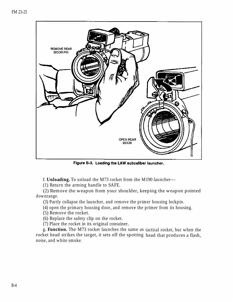
FM 23-25
f. Unloading. To unload the M73 rocket from the M190 launcher—(1) Return the arming handle to SAFE.(2) Remove the weapon from your shoulder, keeping the weapon pointed
downrange.(3) Partly collapse the launcher, and remove the primer housing lockpin.(4) open the primary housing door, and remove the primer from its housing.(5) Remove the rocket.(6) Replace the safety clip on the rocket.(7) Place the rocket in its original container.g. Function. The M73 rocket launches the same as
rocket head strikes the target, it sets off the spottingnoise, and white smoke.
tactical rocket, but when thehead that produces a flash,
B-4

FM 23-25
CAUTIONTHE M73 SUBCALIBER ROCKET OPERATES BETWEEN -23° AND 600C(-10° AND 1400F). FIRE IT ONLY WITHIN THIS TEMPERATURE RANGE.
h. Misfire Procedures. These are the same as for the M-72 series LAW.i. Range Procedures and Safety. These procedures are the same as for the
LAW. The training device can be used against all solid stationary or moving targets.However, because the subcaliber rocket can penetrate 0.124 inches (0.3 15 cm) ofsteel plate or 8 inches (20.32 cm) of soft wood, the target should be constructed of3/16-inch steel plate backed by 3/4-inch plywood.
j. Combat Techniques. These are the same as for the LAW.
B-2. AT4 FRONT SIGHT TEMPLATE AND TARGET SILHOUETTE SHEETThis graphic training aid (GTA 7-2-5), Sight Engagement Trainer, AT4, consists oftwo parts: Part 1, a front sight template, and Part 2, a target silhouette sheet. Theseare used together to train soldiers to obtain a correct sight picture. To obtain thecorrect sight picture for the target speed and range, the front sight template is placedon the target silhouette sheet as shown in Figure B-4. For each of the six targets, thereference number sheet shows the number that should appear in the circle on thefront sight template. The reference number sheet is also used to determine the cor-rect answer for any unit-developed test concerning Training Objective 12 task,Determine the Correct Sight Picture for the M136 (AT4). The local TSC can pro-vide GTA 7-2-5.
B-5

FM 23-25
B-3. AT4 FIELD HANDLING TRAINERThe AT4 field handling trainer (FHT) is an inert device made from an expendedAT4 tactical launcher. It simulates the weight, balance, characteristics, andoperation of the launcher. The FHT is marked with either a gold or yellow l-inchband between the front and rear sights, and with the word “DUMMY” in l-inchletters on the side of the launch tube. The local TSC can convert expendedlaunchers to training devices, but DOD Regulation 5100.76-M requires that theseitems be carefully controlled. The FHT is appropriate for several training situationsthat do not require the M287 tracer trainer, which prevents unnecessary damage tothe tracer trainer. The FHT is used in marksmanship training, FTXs, andinstitutional training to help soldiers learn how to do the following:
Inspect the AT4 for serviceability.Prepare an AT4 for firing.Demonstrate the correct AT4 firing position.Perform misfire procedures.Return an AT4 to carrying position.
B-4. AT4 SUBCALIBER TRACER TRAINERThe M287 subcaliber tracer trainer (Figure B-5) uses the 9-mm M939 trainingpractice-tracer (TP-T) cartridge. When loaded, this trainer simulates the AT4 inweight, balance, and operation. The velocity and trajectory of its ammunition matchthat of the AT4’s HEAT cartridge, but the M287 produces less noise, backblast, andoverpressure. The M287 subcaliber tracer trainer is used in place of the AT4 intraining.
B-6

FM 23-25
a. Description. The M287 tracer trainer is a specially constructed AT4. Unlikethe LAW subcaliber trainer, it is not made from an expended launcher, so it has itsown NSN. It is designed to accept a special rifle barrel that fires a reduced-load9-mm cartridge.
(1) The M287 may be fired at stationary or moving targets. Before it can be firedat a target tank occupied by personnel, the parts of the tank that could suffer damagemust be shielded. The local TSC can provide specifications for modifying tanks to beused as targets for the M287 tracer trainer.
(2) Unlike the M136 AT4 itself and the FHT, the M287 has no band between thefront and rear sights. The trainer has a 9-mm submachine gun barrel, a breachassembly, and a bolt (Figure B-6). The bolt is easily removed to load the 9-mmcartridges and to inspect the barrel for obstructions.
B-7

FM 23-25
(3) If the M287 tracer trainer is damaged, the unit armorer can replace itscomplete firing mechanism, firing rod, bolt, sights, sling, and 9-mm barrel assembly(Figure B-7).
b. Technical Data. The following technical data apply to the M287 subcalibertracer trainer:
Length . . . . . . . . . . . . . 1,020 mm (40 inches)Weight . . . . . . .. . . . . . . . . . . 7 kg (15 pounds)Action . . . . . . . . . . . . . . . . . . . . . . MechanicalSights:
Front . . . . . . . . . . . . . . . . . . . . . . . . . Three-post systemRear . . . . . . . . . . . . . . . . . . . . . . . . . . . Adjustable range, with two peepholes:
2-mm peephole for daylight and 7-mm peepholefor limited visibility
Operating temperature . . . . . . . . . . . . . . . . . . . . . . . . . 10° to 27°C(0° to 1000F)
Muzzle velocity . . . . . . . . . . . . . . .. . . . . . .300 mps(984 fps)
Caliber . . . . . . . .. . . . . . . . . . . . . . . . . . . . . . . . . . . . . . . . . . ..9mm
c. Ammunition. The M939 9-mm tracer cartridge has a lighter powderthan a standard 9-mm bullet. The lighter charge enables the cartridge to
chargeclosely
B-8

FM 23-25
duplicate the trajectory of the AT4 tactical round at ranges out to 700 meters. TheM939 cartridge also has a tracer element to enable the firer to compare the impactof the cartridge with the sight picture. The firer can see the tracer out to 550 meters.Firing the M287 tracer trainer helps the firer learn the correct sight picture formoving targets. The cartridge’s red tip and half-black base (Figure B-8) distinguishesit from standard 9-mm ammunition, which should never be fired from the M287tracer trainer.
d. Function Check. Before the M287 is fired, a function check must beperformed to ensure the trigger and safety mechanisms are operating properly.Function check procedures are shown in Table B-1, page B-10. However, beforeperforming a function check, ensure—
The cocking lever is in the safe (“S”) position.The transport safety pin is fully inserted, with the lanyard wrapped clockwisearound the launcher.
The bolt is removed from the breech.
B-9

FM 23-25
WARNINGLOAD LIVE AMMUNITION ONLY ON THE FIRING LINE. NEVER FIRE THEM287 TRACER TRAINER AT HARD TARGETS LESS THAN 125 METERSFROM THE FIRING LINE, REMAIN CLEAR OF THE FRONT OF THE M287,WHICH MUST BE POINTED DOWNRANGE AT ALL TIMES.
e. Loading. The M287 tracer trainer is loaded as follows:(1) The firer performs the function check and places the M287 tracer trainer on
his shoulder.(2) The trainer looks through the barrel from the rear to verify that it contains no
obstructions. He inspects the cartridge primer to ensure it is not dented, inserts thebolt into the breech (Figure B-9), and presses in and turns the bolt clockwise to the“S” to place it in the safe position (Figure B-10). Then he arms the tracer trainer byturning the bolt clockwise to “F” so that it can be fired (Figure B-11).
(3) With the launcher still on his shoulder, the firer cocks the launcher by placingthe cocking lever in the cocked position.
B-1O

FM 23-25
f. Unloading. With the tracer trainer still on the firer’s shoulder, the trainer orinstructor removes the bolt by turning it counterclockwise past the “S,” then pullingthe bolt from the breech (Figure B-12). If more rounds are to be fired, he removesthe expended cartridge and reloads the bolt.
B-11

FM 23-25
g. Reloading. With the tracer trainer still on his shoulder, the firer places thecocking lever in the safe position, keeping the tracer trainer on his shoulder andpointing toward the target. The trainer reloads the tracer trainer and prepares it forfiring.
DANGERNEVER TOUCH THE TRIGGER WHILE RELOADING.
h. Misfire Procedures. In the event of a misfire—(1) Immediately shout “Misfire!”(2) Release the forward safety, recock the launcher, and ensure the cocking lever
is erect. Fully depress and hold down the forward safety, then aim and press the redtrigger button.
(3) If the tracer trainer still fails to fire, repeat the two previous steps.(4) If the launcher fails to fire again, release the forward safety, maintain your
firing position, and return the cocking lever to the safe position.(5) Notify the training supervisor.(6) If a real misfire occurs that cannot be corrected by following the steps
previously discussed, the trainer or assistant trainer on duty must ensure the cockinglever is in the safe position and that the forward safety is in the vertical position. Hemust then insert the transport safety pin and remove and inspect the cartridge. If theprimer is dented, he replaces it, disposing of the old one IAW range safety SOP. Ifthe primer is not dented, he notifies DS maintenance to inspect the bolt firing pin fordamage. He then reloads the tracer trainer and continues the training exercise.
i. Range Procedures and Safety. These are the same as for the M136 AT4.
B-12
FM 23-25
APPENDIX C
PERFORMANCE EVALUATIONS
The trainer administers performance evaluations to determine how muchsoldiers have learned. Those who fail should be retrained and retested, andthose who pass should help retrain and evaluate those who did not.Instructions are given for right-handed firers: the M136 AT4 may only befired right-handed, but the M72-series LAW may be fired left-handed, ifprocedures are reversed. Tasks are generic to both light antiarmor weapons.Conditions and standards may also be generic but, if not, are given by weapon.
TASK 1: Perform serviceability checks on a light antiarmor weapon.
CONDITIONS: Given an expended light antiarmor weapon under suitable condi-tions or in an appropriate location.
M72-Series LAW
STANDARDS: The firer performs the following actions:
TRAINING AND EVALUATION1. Inspects the launcher to ensure it has no cracks, dents, or bulges.
2. Ensures the trigger-arming handle is present and in the SAFE position.
3. Checks the rubber boots around the trigger bar and detent for cracks, tears, anddeterioration.
4. (M72A2 only) Inspects the data plate on the right forward side of the launcher toensure the words “with coupler” appear on the first line. If not, informs the trainer.
M136 AT4
STANDARDS: The firer performs the following actions:
TRAINING AND EVALUATION1. Ensures the launcher has no cracks, dents, or bulges, or reports these defects tothe instructor.
2. Ensures the transport safety pin is in place, or reports this defect to the instructor.
C-1

FM 23-25
3. Ensures the cocking lever is in the SAFE (uncocked) position, or reports thisdefect to the instructor.
4. Ensures the muzzle cover is intact, or reports this defect to the instructor.
5. Ensures the color-coded band is correct, or reports this defect to the instructor.
6. Ensures the sights function properly, or reports this defect to the instructor.
7. Ensures the venturi has no foreign objects, or reports this defect to the instructor.
8. Ensures the forward safety functions properly, or reports this defect to theinstructor.
9. Ensures the red trigger button is not broken or missing, or reports this defect tothe instructor.
10. Ensures the shoulder stop is not broken or damaged, or reports this defect tothe instructor.
11. Ensures the carrying sling is not frayed and is firmly attached to the launch tube,or reports this defect to the instructor.
RESULTSGO NO-GO
Critique and grade the soldier.
TASK 2: Place a light antiarmor weapon into operation.
CONDITIONS: Given an expended light antiarmor weapon (FHT) on a range or ingarrison.
M72-Series LAW
STANDARDS: The firer performs the following actions, in sequence:
TRAINING AND EVALUATION1. Removes the rear cover pull pin.
2. Releases the rear cover and sling assembly.
3. Extends the launcher vigorously and ensures it is fully extended.
4. Places the launcher on his firing shoulder.
5. Checks the backblast area.
6. Pulls the arming handle out.
7. Sights.
C-2
FM 23-25
M136 AT4
STANDARDS: The firer performs the following actions, in sequence:
TRAINING AND EVALUATION1. Cradles the AT4 in his arms.
2. Removes the transport safety pin.
3. Unsnaps and unfolds the shoulder stop.
4. Places the AT4 on his shoulder.
5. Releases the sights.
6. Checks the backblast area.
7. Places cocking lever in the ARMED (cocked) position.
8. Fully depresses and holds down the forward safety.
RESULTSGO NO-GO
Critique and grade the soldier.
TASK 3: Demonstrate the standing position used to fire a light antiarmor weapon.
CONDITIONS: Given a target and an expended light antiarmor weapon in any suit-able location.
STANDARDS: The firer demonstrates the standing position as follows:
TRAINING AND EVALUATION
M72-Series LAW
1. Faces the target by executing a half-left face turn and spreading his feet acomfortable distance apart.
2. Places the launcher on his shoulder with his left hand directly under the forwardportion of the launcher.
3. Places his right elbow against his body for stability.
C-3
FM 23-25
M136 AT4
1. Faces the target by executing a half-left face turn and spreading his feet acomfortable distance apart.
2. Places the launcher on his shoulder and grasps the sling near the launcher’smuzzle with his left hand.
3. Places the right elbow against his body for stability.
RESULTSGO NO-GO
Critique and grade the soldier.
TASK 4: Demonstrate the kneeling position used to fire a light antiarmor weapon.
CONDITIONS: Given a target and an expended light antiarmor weapon in a suitablelocation, with the soldier in the standing position.
STANDARDS: The firer demonstrates the kneeling position as follows:
TRAINING AND EVALUATION1. Kneels on his right knee, with his right thigh at a 90° angle to the line of aim.
2. Sits back on his right heel, shifting his weight forward.
3. Rests his upper left arm forward of his left knee.
4. Places his right arm against his body.
RESULTSGO NO-GO
Critique and grade the soldier.
TASK 5: Demonstrate the sitting position used to fire a light antiarmor weapon.
CONDITIONS: Given a light antiarmor weapon training device or expended launch-er in a suitable location, with the soldier in the standing position.
STANDARDS: Each firer demonstrates the sitting position as follows:
TRAINING AND EVALUATION1. Keeps the launcher pointed toward the target.
2. Executes a half-left face turn and sits with his legs crossed.
C-4
FM 23-25
3.
4.
5.
Places the launcher on his right shoulder.
Leans slightly forward from his hips.
Rests his elbows forward of his knees to avoid bone-to-bone contact.
RESULTSGO NO-GO
Critique and grade the soldier.
TASK 6: Demonstrate the prone position used to fire a light antiarmor weapon.
CONDITIONS: Given a target and an expended light antiarmor weapon (FHT) in asuitable location.
STANDARDS: The firer demonstrates the prone position as follows:
TRAINING AND EVALUATION1. To keep clear of the backblast area, lies down at an angle of not less than 45degrees from the line of fire.
2. Keeps his back straight and his right leg directly on line with his right hip andright shoulder.
3. Moves his left leg as far as possible to ensure comfort.
4. Holds both elbows well below the launcher.
5. Checks the backblast area to ensure that no part of his body is in it.
6. Holds his head as steady as possible, with his firing eye lined up with the sights.
RESULTSGO NO-GO
Critique and grade the soldier.
TASK 7: Identify enemy vehicles and weapons.
CONDITIONS: Given ten vehicle identification cards (GTA 17-2-13).
STANDARDS: The soldier correctly identifies eight out often vehicles or weapons bynomenclature.
RESULTS
Critique and grade the soldier.GO NO-GO
C-5

FM 23-25
TASK 8: Estimate range.
CONDITIONS: Given stationary, partly exposed, or fully exposed targets at rangesbetween 50 and 250 meters, during daylight, in weather conditions where all targetsare visible. Targets include personnel, equipment, silhouettes, and vehicles.
STANDARDS: The soldier states the distance to each target with no more than 20percent error.
RESULTSGO NO-GO
Critique and grade the soldier.
TASK 9: Apply the correct lead for a target.
CONDITIONS: Given a sight template, a series of ten flank, frontal, and oblique sil-houettes of armored targets, rates of movement, and ranges. (At least threedifferent views, speeds, and ranges are given.)
STANDARDS: The soldier uses correct sighting procedures and correctly applies thelead eight out often times.
RESULTSGO NO-GO
Critique and grade the soldier.
TASK 10: Perform misfire procedures on a light antiarmor weapon.
CONDITIONS: Given a previously fired light antiarmor weapon and instructionsthat the weapon has misfired, on a suitable firing range, under simulated combat con-ditions, in any lighting conditions.
M72-series LAW
STANDARDS: The soldier applies misfire procedures as follows and tries to fire theM72-series LAW. If the weapon still fails to fire, he disposes of it IAW unit SOP:
TRAINING AND EVALUATION1. Immediately squeezes the trigger bar again.
2. If the LAW still does not fire, tries to place the trigger arming handle on SAFE.
C-6
FM 23-25
3. Removes the launcher from his shoulder and partly collapses it (10 to 15centimeters or 4 to 6 inches), keeping the launcher pointed upward and downrange.
4. Extends the launcher.
5. If the LAW fails to fire again, squeezes the trigger, tries to return the weapon toSAFE, partly collapses the launcher, and sets the weapon aside.
M136 AT4
STANDARDS: The soldier performs combat misfire procedures on the AT4 asfollows:
TRAINING AND EVALUATION1. Releases the forward safety with his right hand.
2. Recocks the firing mechanism using the cocking lever.
3. Presses and holds down the forward safety, aims, and presses the trigger.
4. If launcher still fails to fire, repeats Steps 1 and 2.
5. If the launcher again fails to fire, returns the cocking lever to the SAFE(uncocked) position.
6. Removes the weapon from his shoulder, keeping it pointed toward the target.
7. Replaces the transport safety pin.
8. Informs instructors that he would break the sights off in combat to indicate amisfired weapon.
9. Places the launcher on the ground, pointing toward the target.
RESULTSGO NO-GO
Critique and grade the soldier.
TASK 11: Return the light antiarmor weapon to its carrying configuration.
CONDITIONS: Given an expended light antiarmor weapon in a suitable location.
STANDARDS: The soldier performs the following actions, in sequence:
M72-series LAW
TRAINING AND EVALUATION1. Pushes in the trigger arming handle.
C-7
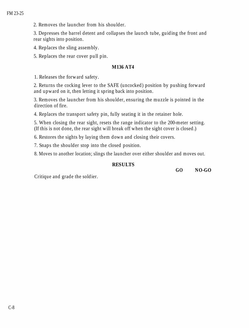
FM 23-25
2. Removes the launcher from his shoulder.
3. Depresses the barrel detent and collapses the launch tube, guiding the front andrear sights into position.
4. Replaces the sling assembly.
5. Replaces the rear cover pull pin.
M136 AT4
1. Releases the forward safety.
2. Returns the cocking lever to the SAFE (uncocked) position by pushing forwardand upward on it, then letting it spring back into position.
3. Removes the launcher from his shoulder, ensuring the muzzle is pointed in thedirection of fire.
4. Replaces the transport safety pin, fully seating it in the retainer hole.
5. When closing the rear sight, resets the range indicator to the 200-meter setting.(If this is not done, the rear sight will break off when the sight cover is closed.)
6. Restores the sights by laying them down and closing their covers.
7. Snaps the shoulder stop into the closed position.
8. Moves to another location; slings the launcher over either shoulder and moves out.
RESULTSGO NO-GO
Critique and grade the soldier.
C-8

FM 23-25
APPENDIX D
SUGGESTED DESIGN FOR COMBINED LIGHTANTIARMOR RANGE
This appendix provides basic guidance for units to establish a range complexfor light antiarmor weapons. The complex described may be used formultilevel training and firing of light antiarmor weapons; both subcalibertrainers and live HE ammunition may be used on the same range. Trainingareas should be near, but not adjacent to, the firing line. The firing line shouldbe designed to allow personnel to observe firing from the side. The targetarray should include stationary targets composed of F-type targets or the hullsof hard targets (APCs or tanks), a moving target (a target on track or amanned moving target tank [MMTT]), and bunkers. This allows the firer toengage a variety of targets and to develop his skills in the various types ofengagements.
D-1. FIRING LINEThe firing line should be organized to allow for the 100-meter AT4 backblast(Figure D-l). Also, at least 20 meters must be allowed between firing points. Thebackblast area must be fenced, roped, or marked in some way, so that soldiers knownot to enter it when firing is being conducted. A range that meets the requirementsof the AT4 will also meet the requirements of the LAW.
D-1

FM 23-25
D-2. TARGET ARRAYThe target array should include targets at ranges of 100 to 700 meters (Figure D-2).This enables the unit to conduct advanced instructional fire on targets located be-yond the weapons’ maximum effective ranges. Standard vehicle silhouettes or tankhulls should be used for stationary targets. Selected targets should be positioned be-hind mounds of earth to simulate vehicles in defilade or partly behind trees or otherobjects. Firers adjust their points of aim accordingly. Targets should also be posi-tioned to allow firers to engage flank, frontal, and oblique targets. Bunker targetsshould be placed within the target array at ranges of 100 to 400 meters. Bunker tar-gets should be no more than 1 meter high or 2 1/2 to 3 meters wide. Moving targetsilhouettes should travel along a track or road so the firers can engage fast mov-ing targets from both flank and oblique angles. The moving targets should beplaced at ranges of 150 to 600 meters and should enter and exit from the flanksoutside the range fan. Firers may only use HE weapons to engage hard targets.This reduces the damage to other targets the unit must maintain such as F-typesilhouettes and bunkers.
D-2

FM 23-25
APPENDIX E
FIRING TABLES AND EXAMPLE SCORECARDS
This appendix provides firing tables for the subcaliber gunnery trainersdiscussed in this manual. It also includes an example completed scorecard foreach light antiarmor weapon. All instructional and qualification firing tablesare conducted on suitable ranges with ammunition designated in the firingtables. Some tables are fired in daylight, others in limited visibility, but allhave some NBC firing (Table E-l).
E-1. M72-SERIES LAWThe M190 35-mm subcaliber device is used to fire the instructional firing tables forthe M72-series LAW and DA Form 7323-R (M72-Series LAW Scorecard) is used toscore them. Figure E-1 shows an example of the completed form; The instructionalday and night firing tables for the LAW are provided in Tables E-2 and E-3.
NOTE: A blank copy of the form is located at the end of this publication for localreproduction on 8 l/2-inch by 1l-inch paper.
E-1

FM 23-25
E-2

FM 23-25
E-3

FM 23-25
E-2. M136 AT4The M287 9-mm tracer bullet trainer is used to fire the instructional, qualification,and advanced instructional firing tables for the M136 AT4, and DA Form 7324-R(M136 AT4 Scorecard) is used to score them. A copy of this form is located at theend of this publication for local reproduction on 8 l/2-inch by 1l-inch paper.Figure E-2 shows an example of the completed form; the instructional, qualification, andadvanced instructional firing tables for the AT4 are provided in Tables E-4 through E-6(pages E-7 through E-9). The latter firing table must be fired on a separate, more spe-cialized range.
E-4

FM 23-25
E-5

FM 23-35
E-6

FM 23-25
E-7

FM 23-25
E-8

FM 23-25
GLOSSARY
AC Active ComponentANCOC advanced noncommissioned officer courseAN/PVS Army Navy passive vision sightARTEP Army Training and Evaluation Program
backblast The backward blast created by igniting the propellant in aweapon designed to be as recoilless as possible.
blast An explosive or violent detonation that produces a directeffect on its target in addition to radiant heat and overpressureat its point of origin.
BMP a type of non-US fighting vehicle built by the formerSoviet Union
BNCOC basic noncommissioned officer courseBRDM a type of non-US scout car built by the former Soviet UnionBTR a type of non-US personnel carrier built by the former
Soviet Union
C CentigradeCS combat supportCSS combat service support
DA Department of the ArmyDKIE decontamination kit individual equipmentDOD Department of DefenseDS direct support
F FahrenheitFHT field handling trainerfps feet per secondFTX field training exercise
HE high-explosiveHEAT high-explosive antitank
heliborne laser fire and forget (a missile system)HELLFIRE
IAW in accordance withIET initial entry training
Glossary-1

FM 23-25
kmph kilometers per hour
LAW light antitank weapon
METLMILESmmMM’TTMOPPMOUTmphmpsMTP
mission-essential task listMultiple Integrated Laser Engagement Systemmillimeter(s)manned moving target tankmission-oriented protective posturemilitary operations on urbanized terrainmiles per hourmeters per secondmission training plan
NA not applicableNATO North Atlantic Treaty OrganizationNBC nuclear, biological, chemicalNCO noncommissioned officerNSN national stock numberNVD night vision device
overpressureOIC officer in charge
increased atmospheric pressure (positive overpressure), followedby a wave of decreased atmospheric pressure (negativeoverpressure), produced around the origin of an explosive orviolent detonation
promethium
PLDC primary leadership development coursePOI program of instruction
radioactive metallic element of the rare-earth group used toilluminate range markings on the front sight of the M72-seriesLAW
RC Reserve ComponentRPG Anon-US rocket-propelled grenade
STX situational training exerciseSMCT soldier’s manual of common tasksSOP standing operating procedurespan small fragment or chipSTP soldier training publicationSTRAC standards in training commission
Glossary-2

FM 23-25
T R A D O C
TOC tactical operations centerTP training-practice
(US Army) Training and Doctrine Commandtrc track (as used in STRAC manual)TRP target reference pointTSC training support center
Glossary-3

FM 23-25
REFERENCES
SOURCES USEDThese are the sources quoted or paraphrased in this manual.
TM 9-1055-886-12&P Operator and Unit Maintenance Manual for M287 9-MMTracer Bullet Training Device. 25 October 1989.
TM 9-1315-886-12 Operator’s and Unit Maintenance Manual for Launcherand Cartridge, 84 Millimeter: M136 (AT4). 15 May 1990.
TM 9-1340-214-10 Operator’s Manual for 66-MM Light Antitank Weapon(LAW) System M72A1, M72A2 with Coupler, M72A3,and Practice Rocket Launcher M190 with M73 PracticeRocket. 31 May 1991.
TM 11-5855-213-10 Operator’s Manual for Night Vision Sight, Individual-ServedWeapon AN/PVS-4. 1 February 1993.
TM 11-5855-213-23&P Unit and Direct Support Maintenance Manual for NightVision Sight, Individual-Served Weapon, AN/PVS-4.1 June 1993.
TM43-0001-30 Army Ammunition Data Sheets for Rocket Systems,Rocket Fuzes, Rocket Motors, 1 December 1981.
DOCUMENTS NEEDEDThese documents must be available to the intended users of this publication.
DA Form 7323-R M72-Series LAW Scorecard,DA Form 7324-R M 136 AT4 Scorecard.DA Pamphlet 350-38 Standards in Weapons Training. 15 February 1993.
* DOD 5100.76-M Physical Security of Sensitive Conventional Arms,Ammunition, and Explosives. 3 February 1983.
FM 7-7 The Mechanized Infantry Platoon and Squad (APC).15 March 1985.
FM 7-7J The Mechanized Infantry Platoon and Squad (Bradley).7 May 1993.
FM 7-8 The Infantry Platoon and Squad. 22 April 1992.
* This source was also used to develop this publication.
References-1
FM 23-25
FM 25-101GTA 7-2-5GTA 17-2-13STP 7-11BCHM14-SM-TG
STP 21-1-SMCT
TC 90-1
Battle Focused Training. 30 September 1990.Sight Engagement Trainer, AT4 (Parts 1 and 2). 1990.Armored Vehicle Recognition. October 1984.Soldier’s Manual and Trainer’s Guide, MOS 11B, 11C,11H, and 11M, Skill Levels 1/2/3/4.Soldier’s Manual of Common Tasks, Skill Level 1.1 October 1990.Training for Military Operations on Urbanized Terrain.30 September 1993.
READINGS RECOMMENDEDThese readings contain relevant supplemental information.
AR 190-11 Physical Security of Arms, Ammunition, and Explosives.30 September 1993.
AR 385-63 Policies and Procedures for Firing Ammunition forTraining, Target Practice, and Combat. 15 October 1983.
FM 3-5 NBC Decontamination. 23 July 1992.FM 5-250 Explosives and Demolitions. 15 June 1992.FM 20-3 Camouflage. 14 November 1990.FM 90-5 (HTF) Jungle Operations (How to Fight). 16 August 1982.FM 90-10-1 An Infantryman's Guide to Combat in Built-Up Areas.
References-2

FM 23-25
Index-1

FM 23-25
Index-2
FM 23-25
Index-3


FM 23-2517 AUGUST 1994
By Order of the Secretary of the Army:
Official:
GORDON R. SULLIVANGeneral, United States Army
Chief of Staff
MILTON H. HAMILTONAdministrative Assistant to the
Secretary of the ArmyC6883
DISTRIBUTION:
Active Army, USAR and ARNG: To be distributed in accordance with DA Form12-11E, requirements for FM 23-25, Light Antiarmor Weapons (Qty rqr block no.4321).
★ U.S. Government Printing Office: 1994—528-027/80157