uml behavioral refactoring for the specification of ... behavioral refactoring for the... · uml...
TRANSCRIPT

UML Behavioral Refactoring for theSpecification of Complex Software Systems
M.T. Chitra1,2 and Sherly Elizabeth2
1University of Kerala2Indian Institute of Information Technology and Management - Kerala
{chitra,sherly}@iiitmk.ac.in
Abstract. Behavioral models play a prominent role in specifying soft-ware systems by facilitating the abstract behavior views and analyzingthe elementary aspects of a system. The sequence diagram, one of thekey behavioral diagrams in UML, provides intuitive ways to capture re-quirements and scenarios as a sequence of events. The paper proposesa generic framework for effective code generation from UML models.The proposed framework acts as an interexchange format that helps tocombine the structural and behavioral constraints of the system objectsassociated thereby facilitating consistent source code generation. ModelRefactoring contributes to improve the software quality and productiv-ity thus mitigating flaws in the system during the design phase itself.The case study presents the refactoring of online simulation of a milloptimization problem in a thermal power plant system.
Keywords: Behavioral diagrams, Model Refactoring.
1 Introduction
The increasing complexity of the software systems demands the advent of noveleffective development approaches that can overcome the major drawbacks of theexisting development technologies. Model Driven Engineering (MDE), fosteredby Object Management Group (OMG) helps reducing the development costsof complex software systems through the use of technologies like Model DrivenArchitecture (MDA) that supports rigorous analysis of software models [2, 3]. InMDA, models are the primary entities for entitling the system at different levelsof abstraction. Models can help to detect inconsistencies or incompleteness inrequirement model by evaluating the simulation of the scenarios.
The Unified Modeling Language (UML) is one of the prevalent languages usedfor modeling complex safety-intensive software systems. It provides a collectionof modeling notations for design specifications to build models that describe thedifferent views on a system during various stages such as requirements analy-sis and design artifacts of software systems. UML Sequence diagrams are now
51 Research in Computing Science 103 (2015)pp. 51–68; rec. 2015-06-03; acc. 2015-06-20

becoming familiar to represent the behavioral specifications of the complex sys-tems. Sequence diagrams emphasize on modeling the interactions between thecollaborating objects participating in the interactions as a time-ordered set ofmessages [1, 3].
However, UML diagrams fail to specify the semantics in representing theentire information to determine the complete system behavior. The lack of formalsemantic specification for UML makes it difficult to analyze the consistencynotion in these diagrams. Hence, several transformation approaches are beingadopted for analyzing and specifying the consistency of behavioral models whichtransform the UML models into some semantic domain where the consistencyconstraints can be represented and validated. The formal specification languageslike OCL, TOCL, Z, etc. helps to add additional information to the diagramthereby ensuring the completeness of the model.
OCL is a declarative, side-effect free, formal specification language used alongwith UML diagrams for specifying the object constraints and queries on theUML models. It precisely defines the well-formedness rules for UML as well asthe OMG-related metamodels. OCL is mainly used to specify the invariants ofobjects as well as the pre and post conditions of the operations [6].
Representing the dynamic behavior of complex time-safety critical systemsis a rigorous task as well as a tough research problem to be taken care of. Itinvolves the careful analysis of the semantic aspects with respect to the systemconstraints. Moreover, there are no model-based techniques or tools availableso far for analyzing such temporal properties in UML behavioral diagrams, es-pecially in sequence diagrams. Existing approaches use model transformationtechniques that transform the UML models to some other language that sup-ports automated analysis, which are also complex and erroneous.
The Temporal OCL (TOCL) finds its significance in this context. The timeand safety related constraints as well as the behavioral specifications, whichare hard to express using OCL can be specified using TOCL, a temporal logicextension of OCL. In this paper, we evaluate the impact of OCL and TOCL alongwith UML behavioral diagrams to completely represent the system behaviorespecially in safety-critical software environments.
Towards this goal, we provide a refactoring approach to embed the staticas well as the temporal constraints involved in the system behavior through adevelopment chain. It constitutes the generation of the behavioral design modelusing UML sequence diagrams, specification of the constraints using OCL andTOCL, generation of code from the behavioral models by applying the refactor-ing approach and the execution and analysis of generated code. This approachhelps in predicting the system behavior at modeling level itself by comparing thesimulation results with real time results. This consequently allows the scientistsor the researchers to work exclusively at modeling level in order to obtain theoptimized system models. They can analyze the scenario specifications directlyfrom the execution model and can add changes accordingly.
The work focuses on interaction modeling, showcasing the dynamic aspectsof the interaction between the participating objects. The dynamic modeling
52
M.T. Chitra, Sherly Elizabeth
Research in Computing Science 103 (2015)

includes visual specification of the system functionalities in detail, where thefunctionalities are realized through the message passing between the objectsparticipating in the interaction. The paper discusses about the development of aframework which shows the automated refactoring of UML interaction diagrams,especially the sequence diagram designs, to improve the understandability andmaintainability of the design for the efficient source code generation process.
This paper is an extended work and its main new contribution is that theframework has been enhanced with the potential of including a set of safetyand temporal constraints in addition to the static constraints of the system [16].The work proposes a novel approach that yields an interexchange framework toinclude the complex system behaviors into UML Sequence diagram design asconstraints, thereby enriching the model elements with the necessary details ofthe system without affecting its external behavior.
Incompleteness in the generated source code may often arise due to the ab-sence or failure in representing all possible information regarding the objectsthat participate in that system. The constraint specification languages play anintelligent role here, by removing this inconsistency in the model design whichin turn reflects in the completeness of the generated source code. The proposedframework paves the way for improving the software code quality and produc-tivity fulfilling all the specified system requirements during the code generationprocess.
The main contributions of this work can be summarized as follows:
– The behavioral refactoring approach in sequence diagram designs is pro-posed, which paves a way to incorporate static, temporal and safety relatedconstraints into the design and derive a refactored interexchange model fromthe existing SD specification.
– To provide a generic behavioral pattern for implementing the proposed refac-toring methodology in UML models that provides a space for consistent codegeneration of software systems.
The remainder of this paper is structured as follows: Section 2 gives therelated works and identifies and explains the different refactoring activities. Sec-tion 3 describes the proposed refactoring approach. Section 4 presents the im-plementation of the approach through a case study discussion. Finally, Section 5shows the results and discussions part of the case study and Section 6 concludes.
1.1 Background
The software refactoring is an emerging area where a lot of researches are beingcarried out on exploring the ways to address refactoring in a consistent manner.Refactoring revolutionizes the design by applying some effective process for im-proving code quality. The term refactoring was instigated in 1992 by William F.Opdyke in his research work in the context of object-oriented software to supportsoftware evolution and reuse. He defined refactoring as “behavior preserving pro-gram restructurings or transformations containing particular preconditions that
53
UML Behavioral Refactoring for the Specification of Complex Software Systems
Research in Computing Science 103 (2015)

must be verified before the transformation can be applied in order to make thedesign of a program clearer and to make it easier to add new features” [7, 8].
Refactorings can also be applied to reduce or eliminate redundant parts ofprogram codes [7]. Martin Fowler defined the process of refactoring as “a changemade to the internal structure of software to make it easier to understand andcheaper to modify without changing its observable behavior”. He proposed therefactoring catalog which focuses on manual refactoring, demonstrated with ex-amples regarding the principles of refactoring, the useful ways to identify andfind the associated low-level refactoring(s) that helps fixing a code problem in acontrolled and efficient manner [9].
Mens et al., in their review on model-driven refactoring discussed on the latestapproaches in model refactoring and also the various challenges encounteredwhile applying refactoring on model level [13]. Mohamed et al. discussed ontheir the existing model refactoring approaces based on feature based model-driven taxonomy [14]. Most of the investigations focus on UML class diagrams,for applying model refactorings [10]. There are only a few approaches that focusrefactoring behavioral diagrams and prove their behavior preservation propertiesin a standard way. G. Sunye et al. were the first to present a set of refactoring(s),particularly on UML class models and state machine models, and explained howthey can be modeled so as to preserve the behavior of a UML model. They showedthat refactorings can be defined for UML in such a way that their behavior-preserving properties are protected, based on OCL constraints defined at themetamodeling level [11].
Alessandro Folli and Tom Mens used Algebraic Graph Grammar tool tosupport refactoring on the UML designs. They focus on class models and statemachine models and define a metamodel similar to the UML meta model as atype graph. The limitation of this work is that this type graph can represent onlythe simplest version of the UML metamodel [17]. France et al. described a metamodeling approach to pattern-based model refactoring in which refactoring(s)are used to introduce a new design pattern instance to the model [18].
Several formalisms have been suggested to examine model refactoring(s).Most of these propose exhibiting model refactoring in a declarative way. Graphtransformation theory was used in several works for describing model refactoringand formal properties have been used to review these refactoring(s) [15].
Most of the refactoring approaches focused on code-level refactoring and onlya limited works address the model refactoring approaches and especially withclass diagrams [13]. But while taking care of the behavior preservation of designmodels, we need to rely on behavioral models and the constraints associatedwith them. Only a few works are available in the literature with respect torefactoring of behavioral models. None of the existing approaches can be usedto verify operation-based model refactoring that involves changes to operationspecification. The core idea presented in this paper focuses on facilitating theintegration of system behavioral properties throughout the time point at differentabstraction levels one wants to guarantee for the safe or normal execution of thesystem.
54
M.T. Chitra, Sherly Elizabeth
Research in Computing Science 103 (2015)

2 The Conceptual Approach
2.1 Refactoring the Behavioral Specifications
Model transformation is the process of modifying the source model to producethe target model. Refactoring is a model transformation approach which restruc-tures the system by altering its internal behavior without affecting the externalbehavior [1, 2]. Modifying the UML model by enriching with the necessary con-straints will significantly increase the quality of the design as well as the gener-ated source code from it. The process of refactoring enables the model to adaptto future extensions.
By definition, refactoring should ensure behavior-preserving transformationsof an application. It means that the external behavior of the model before andafter the refactoring must remain the same. The major problem faced by design-ers is to measure the actual impact of modifications on the various design views,as well as on the implementation code which serves as a valid proof to prove thecorrectness of system and hence showing the behavior preservation property ofrefactoring approach. Another crucial task here is identifying or determining theexact element to which the refactoring has to be applied.
We are applying the refactoring approach in UML sequence diagrams, whichprimarily shows the behavioral interactions between the objects participatingin the system. Such behavioral transformations need extra care as their changeraises some difficulties.
In the proposed work, the model refactoring is applied to the lifeline modelelement of the sequence diagram design for ensuring the correctness of the sys-tem. Since the primary focus of the sequence diagram is to specify the interactionbetween the collaborating objects, represented as lifelines, it has been chosen asthe focal point for refactoring.
We also need to justify why the behavior preservation condition holds forthese model transformations:
– Adding the constraint schema into the lifeline model element does not makeany modification to the behavior of that element. Rather, we are only givingspace to group all the data related to that model element into a commonpoint in order to improve the understandability.
The overall architecture of the refactoring process proposed in this work is shownin Figure 1.
The XML Metadata Interchange (XMI) is OMG standard interchange for-mat used in UML models for exchanging metadata information via XML. Itincludes information about elements in a model and their relationships. Thetransformation of the models into XMI is indeed a breakthrough in facilitatinginteroperability across various tools and platforms [5]. The XMI generated wouldthen be fed into an XMI parser to retrieve the meta model information which in-turn is used for the generation of source code. Besides, OCL and TemporalOCLalso supplements more precise information specification in the UML behavioralmodel. The work is an attempt to allow the specification of inter-object scenariosfor object-oriented system models in a succinct expressive manner.
55
UML Behavioral Refactoring for the Specification of Complex Software Systems
Research in Computing Science 103 (2015)

Fig. 1. Architecture of the Refactoring process
2.2 Generation of the OCL-TOCL Framework
The work focuses on developing X-CodeFrame, an XML code framework for rep-resenting OCL and TOCL constraints into UML behavioral models, especiallythe Sequence diagram model thereby facilitating automatic behavioral code gen-eration. This approach helps in simplifying the transformation of the static, tem-poral and safety-related constraints of the system, thereby smoothening the codegeneration process.
The constraints that are typically hard to express in OCL, which entitles thetemporal and safety related issues of the system are specified using the temporalOCL (TOCL). The static as well as the temporal constraints specified for asystem using OCL and TOCL are parsed for framing the constrained elements inorder to generate the framework as per the defined schema [schema No-Fig.]. Theextracted constraints are then set appropriately into the OCL-TOCL frameworksby matching the context < classname > attribute.
An XML Schema Definition (XSD) typically called an XML schema, is thede facto standard for describing XML documents, controlled by the World WideWeb Consortium (W3C). The XML schema formally defines the XML document
56
M.T. Chitra, Sherly Elizabeth
Research in Computing Science 103 (2015)

structure accompanying the rules for data content and semantics. The OCLschema proposed here defines an XSD file that provides the design pattern ofhow the constraints will set within the XMI file obtained after the refactoringprocess.
The OCL-TOCL schema is the backbone of the proposed UML refactor-ing process. Based on the defined schema rules, the constraints are embeddedinto the XMI file of the UML model thereby refactoring it for quality sourcecode generation. The basic types that we are considering for the schema frame-work generation are the invariants, methods, pre-condition and post-conditionoperations.
The schema defines the specification rules for framing the constraints appro-priately associated with each of the objects participating in the system interac-tion. For each class defined in the constraint files (OCL/TOCL) there will bean < extendedConstraints > tag generated which is the root element for theconstraint construction framework. All the constraints that belong to a partic-ular class will come to an individual < extendedConstraints > tag created forthat class. It includes the class name details using the attribute context and alsostores the file type within the type attribute.
Fig. 2. Extended constraints
The schema template structure for adding invariants into the OCL-TOCLframework is as follows. The < MethodDetails > tag is the main tag elementinside the < extendedConstraints > tag which represents the whole constraintblock within a particular class based on the nature of the constraints. The< body > tag element sets the constraints within the < MethodDetails > appro-priately. The < constraints > tag is the complex type tag set that helps in iden-tifying all the constraint expressions, operations etc in the < MethodDetails >and include these entities as individual elements under the < constraint >tag within it. The schema template structure for generation of an operation ormethod is as shown in Fig. 3.
For the execution of a method in any complex system generally includes aprecondition which must be considered for a safe system functioning, a bodypart which includes the actual functionality to be performed and a postcondi-tion operation in which the status of the generated output is checked for fur-ther processing of the system. Hence the syntax for generation of the methodschema also include these as the key factors while framing data with respect toa method. The < precondition > tag element helps in representing all thoseconditions for checking the pre-conditions that should satisfy or perform if anybefore performing the actual method body. The < body > tag include the ex-
57
UML Behavioral Refactoring for the Specification of Complex Software Systems
Research in Computing Science 103 (2015)

Fig. 3. Schema template structure for generation of an operation or method
pression and operations that have to be taken place within that method andthe < postcondition > tag represents all those constraints that must have to beexecuted after the method execution.
The generation of java class files corresponding to the OCL schema is doneusing JAXB (Java Architecture for Xml Binding), which directly binds theXSD/XML element to particular fields of java classes and vice versa using theproperties marshalling and unmarshalling.
The OCL files containing the static constraints and the TOCL files whichcontain the temporal and safety related constraints for the system are parsed.The constraints are parsed and extracted in a way that helps in fixing the con-text to which the respective specification refers to in the generated OCL-TOCLframeworks. The constraints extracted are set with the associated java objectsof the java classes created using JAXB.
The generated OCL TOCL frameworks are then injected into the XMI of theSequence diagram model based on the lifelines associated with it.
The OCL -TOCL framework generation process is shown as Algorithm 1.
Algorithm 2 explains the process of filling the constraint objects with appro-priate constraint body tag elements.
58
M.T. Chitra, Sherly Elizabeth
Research in Computing Science 103 (2015)
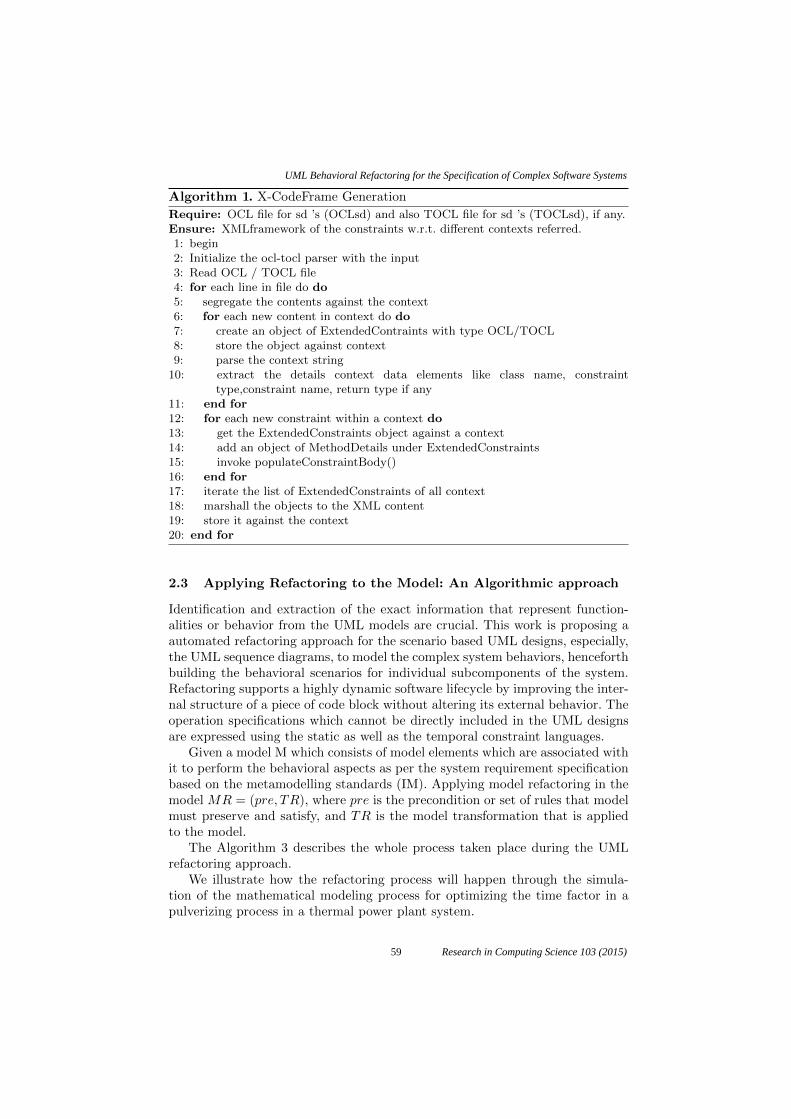
Algorithm 1. X-CodeFrame Generation
Require: OCL file for sd ’s (OCLsd) and also TOCL file for sd ’s (TOCLsd), if any.Ensure: XMLframework of the constraints w.r.t. different contexts referred.1: begin2: Initialize the ocl-tocl parser with the input3: Read OCL / TOCL file4: for each line in file do do5: segregate the contents against the context6: for each new content in context do do7: create an object of ExtendedContraints with type OCL/TOCL8: store the object against context9: parse the context string
10: extract the details context data elements like class name, constrainttype,constraint name, return type if any
11: end for12: for each new constraint within a context do13: get the ExtendedConstraints object against a context14: add an object of MethodDetails under ExtendedConstraints15: invoke populateConstraintBody()16: end for17: iterate the list of ExtendedConstraints of all context18: marshall the objects to the XML content19: store it against the context20: end for
2.3 Applying Refactoring to the Model: An Algorithmic approach
Identification and extraction of the exact information that represent function-alities or behavior from the UML models are crucial. This work is proposing aautomated refactoring approach for the scenario based UML designs, especially,the UML sequence diagrams, to model the complex system behaviors, henceforthbuilding the behavioral scenarios for individual subcomponents of the system.Refactoring supports a highly dynamic software lifecycle by improving the inter-nal structure of a piece of code block without altering its external behavior. Theoperation specifications which cannot be directly included in the UML designsare expressed using the static as well as the temporal constraint languages.
Given a model M which consists of model elements which are associated withit to perform the behavioral aspects as per the system requirement specificationbased on the metamodelling standards (IM). Applying model refactoring in themodel MR = (pre, TR), where pre is the precondition or set of rules that modelmust preserve and satisfy, and TR is the model transformation that is appliedto the model.
The Algorithm 3 describes the whole process taken place during the UMLrefactoring approach.
We illustrate how the refactoring process will happen through the simula-tion of the mathematical modeling process for optimizing the time factor in apulverizing process in a thermal power plant system.
59
UML Behavioral Refactoring for the Specification of Complex Software Systems
Research in Computing Science 103 (2015)

Algorithm 2. The populateConstraintBody()
Require: ExtendedConstraints object for a contextEnsure: Modified ExtendedConstraints object with constraint body1: begin2: if Precondition then3: create an object of ExtendedConstraints.MethodDetails.Preconditions4: create Constraints object within Preconditions5: set the expression string to the Precondition constraints6: else if Postcondition then7: create an object of ExtendedConstraints.MethodDetails.Preconditions8: create Constraints object within Preconditions9: set the expression string to the Precondition constraints
10: else if Body or inv then11: create an object of ExtendedConstraints.MethodDetails.Preconditions12: create Constraints object within Preconditions13: set the expression string to the Precondition constraints14: end if15: return the modified object of ExtendedConstraints16: end
Algorithm 3. The Automated UML Refactoring Process
Require: ExtendedConstraints object for a contextEnsure: Modified ExtendedConstraints object with constraint body1: begin2: if Precondition then3: create an object of ExtendedConstraints.MethodDetails.Preconditions4: create Constraints object within Preconditions5: set the expression string to the Precondition constraints6: else if Postcondition then7: create an object of ExtendedConstraints.MethodDetails.Preconditions8: create Constraints object within Preconditions9: set the expression string to the Precondition constraints
10: else if Body or inv then11: create an object of ExtendedConstraints.MethodDetails.Preconditions12: create Constraints object within Preconditions13: set the expression string to the Precondition constraints14: end if15: return the modified object of ExtendedConstraints16: end
3 Case Study : The Coal Pulveriser OptimizationProblem
We demonstrate the capability of the proposed refactoring approach thoughthe online coal pulverizing mill optimization problem [16]. In this system, wehave considered both the static as well as the behavioral properties involved inthe pulverizing process to demonstrate the applicability of the approach. The
60
M.T. Chitra, Sherly Elizabeth
Research in Computing Science 103 (2015)

main function of the pulverizing mill is to grind and dry the moisturized rawcoal supplied to it from the coal storages. The two main classes involved in thepulverisation process in a coal mill are the CoalStorage and the Pulveriser.
The proposed system behavior is modeled using the UML sequence diagram.The safety and time related constraints as well as the static constraints are ex-pressed as TOCL and OCL files respectively. The model is exported as an XMIfile and is parsed appropriately for extracting the relevant tag data elements forthe code generation process. The OCL as well as the TOCL files are simultane-ously parsed to extract the relevant details into the corresponding tag elementsin the XMI file using the proposed X-CodeFrame framework.
The UML together with the OCL and TOCL helps in representing the factsthat belong to the behavioral level completeness of the system. The constraintsof the pulveriser which cannot be typified visually are represented using OCLand TOCL files. The pre and post conditions to be satisfied and the invariantsof the system model specified using the OCL file are embedded to the designmodel by the applying the refactoring approach proposed in the work in orderto accomplish the model consistency. The pulveriser optimization process simu-lation is performed by transforming the mathematical system model using theObject Constraint Language. Along with the sequence diagram model informa-tion the temporal as well as the static constraints related with the CoalStorageand the Pulveriser sub systems are also supplied to the model in order to enrichthe design data for the code generation process.
3.1 Simulating the Online Coal Pulverisation Process Optimization
The following mathematical model explains the coal pulverisation process [19,20]. The model is converted to discrete time form for the purpose of online im-plementation. Figure 2 illustrates the overall online pulverising mill optimizationprocess. The mill model variables are monitored dynamically in real time. Theunknown parameters in the equations are estimated using evolutionary compu-tation technique (Genetic Algorithms) and system simulation techniques basedon the on-site measurement data. The normal pulverisation process is describedmathematically using the following equations:
61
UML Behavioral Refactoring for the Specification of Complex Software Systems
Research in Computing Science 103 (2015)

Fig. 4. Online mill performance simulation
The main input variables supplied to the pulveriser system include raw coalflow into the pulveriser, primary air differential pressure and primary air inlettemperature. The output variables include pulveriser differential pressure, outlettemperature and mil current. The online coal mill optimization process is spec-ified as a constraint file as shown below. During the refactoring process theseequations are affixed under the < body > tag elements section of the Pulveris-ing() method call.
The values of the constant co-efficients are obtained using the Genetic Al-gorithm. The code generation helps the researchers and experienced engineersin analyzing and comparing the simulation results of the online mill model withthe real plant data set values and thereby improving the mill performance.
3.2 OCL Constraints in the Coal Pulverising Process
This section presents the approach by specifying the temporal properties associ-ated with the pulverisation process in a coal-fired thermal power plant system.The structural constraints that must necessarily hold true or checked during thepulverization process are represented as invariants using the OCL file.
Mc = ((Wc - (k15 * self.Mc)) * T )
Mpf = (((k15 * self.Mc) - (self.Wpf)) * T)
DPmpd = (((k11 * self.Mpf + (k12 * self.Mc) - (k13 * self.DPmpd))) * T)
62
M.T. Chitra, Sherly Elizabeth
Research in Computing Science 103 (2015)

Tout = (((((k1 * self.Tin) + k2) * self.Wair) - (k3 * self.Wc) -
(((k4 * self.Tout) + k5) * (self.Wair + self.Wc)) +
k14 * ((k6 * self.Mpf) + (k7 * self.Mc) + k8) +
((k17 * self.Tout))) * T) + self.Tout
P = (k6 * self.Mpf) + (k7 * self.Mc) + k8
DPmill = k9 * self.DPpa
Wpf = k16 * self.DPpa + self.Mpf
The following are a few constraints associated with the two classes CoalStor-age and PowerPlant in the thermal power plant system:
context CoalStorage inv cosize:CoalSize=20
context CoalStorage inv hval: HGI=55
The invariants that must hold true for the CoalStorage class are:
context CoalStorage inv cosize:CoalSize=20
context CoalStorage inv hval: HGI=55
The typical invariants that must hold for the Pulveriser class are as shownbelow.
context Pulveriser inv: Wc $<=$ 45
context Pulveriser inv: Wair $<=$ 75
context Pulveriser inv: Tin $<=$ 300
context Pulveriser inv: DPpa $<=$ 180
context Pulveriser inv: outlet temperature $<=$100
context Pulveriser inv: DPmill $<=$ 500
context Pulveriser inv: P $<=$ 60
context Pulveriser inv: if a.Stage = 3 then
Speed=54 else Speed=52 endif
context Pulveriser inv:if a.Stage = 3
then self.Type = ’HP803PXBowl’
else self.Type = ’XRP763BowlRoller’endif
context Pulveriser inv:if CoalHGI = 55 and CoalMoisture = 0.1
and CoalFineness = 0.7 then
if a.Stage = 3 then self.Capacity2 = 39.9 else
self.Capacity2 =33.8
endif
else self.Capacity2 $ <>$ 0
endif
3.3 Safety and Temporal Constraints in the Coal PulverizingProcess
The temporal constraints involved in the coal milling process include the safetyand time related aspects of all the classes or objects participating in that process.For the CoalStorage class the main temporal constraints involved are:
63
UML Behavioral Refactoring for the Specification of Complex Software Systems
Research in Computing Science 103 (2015)

1. Failure in the level of the minimum storage level or maximum storage leveloccurred; that means the coal level exceeds the limit of the maximum storagelevel or has reached the minimum level.
For the Pulverizer class the main temporal constraints to be considered are:
1. The system is in initialization mode until all the physical sub components orunits inside the pulveriser are in ready mode and all the external attributessupplied to the system satisfie the normal range values for proper functioningof it or a failure in the level of coal quantity supplied to the pulverizing millhas been identified.
2. The system is in the normal mode, which is the standard operating modewhen the program tries to maintain the raw coal level in the pulveriser be-tween the level of values with which all physical units are operating correctly.
The below listed are a few safety and temporal constraints associated withthe coal pulverisation process.
When the Pulveriser system is in the initialization mode, it remains in thismode until all physical units are ready or a failure in the pulverising mill hasoccurred.
Instantly the program recognizes a failure in the Coal Mill system until itgoes into the rescue mode.
Failure of any of the physical or measured units except the coal mill puts theprogram in to degrade mode.
When the Coal Mill system is in the initialization mode and a failure of thecoal mill is detected, it puts the program into emergency stop.
64
M.T. Chitra, Sherly Elizabeth
Research in Computing Science 103 (2015)

4 Results and Discussions
The UML SD design model for the coal pulverization process is shown in Fig-ure 5:
Fig. 5. UML Sequence diagrams
The OCL framework generated for the OCL constraints given below is asshown in Figure 6. Here the CoalStorage class has two constraints associatedwith it, which are converted into two < MethodDetails > elements under the< ExtendedConstraints > object tag.
The OCL-TOCL framework generated for the mill optimization process is asfollows.
The framework generated for the preconditions and postconditions specifiedas OCLconstraints that must satisfy for the Pulveriser object is:
The code framework generated for invariants of the Pulveriser subsystem is:
5 Conclusion
This paper concentrates on providing a generic framework for refactoring thespecification of complex systems modeled using UML2.0 sequence diagrams. Itfocuses on combining the structural and the behavioral constraints, thereby of-fering a path for consistent and quality source code generation. The system hasbeen formally modeled using the OCL/TOCL language to provide explicit andprecise system information to the design. A generic template framework hasbeen built based on the constraints as well as the UML sequence metadata of
65
UML Behavioral Refactoring for the Specification of Complex Software Systems
Research in Computing Science 103 (2015)

Fig. 6. The OCL framework generated for the OCL constraints
Fig. 7. The XCodeFrame generated for the online coal mill optimization process forthe Pulveriser subsystem
the system by using refactoring approach. The proposed method facilitates themathematical verification of pulveriser system in a thermal power plant. Therepresentation of extra information as static as well as temporal constraints at-tached to certain locations of the objects lifelines in the sequence diagram allowsthe identification of gaps and contradictory specifications during the source codegeneration process.
6 Acknowledgments
The authors would like to thank the Control and Instrumentation Group, CDAC,Thiruvanathapuram for providing the raw plant data of pulverising mill which isused for modeling and validating the system. This work is supported by SPEED-IT programme of Kerala State IT-Mission under Govt.of Kerala.
66
M.T. Chitra, Sherly Elizabeth
Research in Computing Science 103 (2015)

Fig. 8. The preconditions and postconditions specified as OCLconstraints that mustsatisfy for the Pulveriser object
Fig. 9. The code framework generated for invariants of the Pulveriser subsystem
67
UML Behavioral Refactoring for the Specification of Complex Software Systems
Research in Computing Science 103 (2015)

References
1. Unified Modelling Language, http://www.uml.org/.2. Object Management OMG. Unified Modeling Language Specification 2.0:
Infrastructure. Technical Report ptc/03-09-15, OMG (2003).3. G. Booch, J. Rambaugh, and I. Jacobson, The Unified Modeling Language
User Guide, Addison-Wesley (1999).4. Model Driven Architecture, White Paper, Object Management Group OMG,
May (2014).5. XML Metadata Interchange, www.omg.org/spec/XMI/6. OMG, Object Constraint Language (OCL) Specification, version 2.0,2006
http://www.omg.org/spec/OCL/2.0/7. Opdyke, W.F.: Refactoring: A Program Restructuring Aid in Designing
Object-Oriented Application Frameworks, PhD thesis. Univ. of Illinois(1992).
8. Roberts, D.: Practical Analysis for Refactoring. PhD thesis. Univ. of Illinois(1999).
9. Fowler, Martin: Refactoring: Improving The Design of Existing Code. Pear-son Education India (1999).
10. Astels, Dave: Refactoring with UML. In: 3rd International Conference oneXtreme Programming and Flexible Processes in Software Engineering, 67–70 (2002).
11. Suny, G., Pollet, D., Le Traon, Y., Jzquel, J. M.: Refactoring UML models. InInternational Conference on Unified Modeling Language UML -2001. LNCS2185. Springer Berlin Heidelberg, 134–148 (2001).
12. Maddeh, M., Romdhani, M., Ghdira, K.: Classification of Model RefactoringApproaches. Journal of Object Technology, 8.6, 143–13958 (2009)
13. Mens, Tom, Tourw, Tom: A survey of software refactoring. Software Engi-neering, IEEE Transactions on 30.2, 126–139 (2004).
14. Mens, Tom, Taentzer, Gabriele, Mller, D.: Model-driven Software Refactor-ing. Model-Driven Software Development: Integrating Quality Assurance,170–203 (2008).
15. Mens, Tom, Taentzer,Gabriele, Mller, Dirk.: Challenges in model refactoring.In: 1st Workshop on Refactoring Tools, University of Berlin. Vol. 98 (2007).
16. Chitra M. T., Elizabeth Sherly.: Refactoring sequence diagrams for codegeneration in UML models. In IEEE Int. Conf. on Advances in Computing,Communications and Informatics ICACCI, 2014, 208–212 (2014).
17. Folli, Alessandro, Mens, Tom.: Refactoring of UML models using AGG. Elec-tronic Communications of the EASST (2008).
18. France, R., Chosh, S., Song, E., Kim, D. K.: A metamodeling approach topattern-based model refactoring. Software, IEEE, 20(5), 52–58 (2003).
19. Y. G. Zhang, Q. H. Wu, J. Wang, G. Oluwande D. Matts, and X.Zhou.:Coal Mill Modeling by Machine Learning Based on Onsite Measurements,Energy Convers. IEEE Trans., 17(4), 549–555 (2002).
20. J. Wei, J. Wang and Q. H. Wu.: Development of a Multisegment Coal MillModel Using an Evolutionary Computation Technique, IEEE Trans.EnergyConvers., 22(3), 718–727 (2007).
68
M.T. Chitra, Sherly Elizabeth
Research in Computing Science 103 (2015)