uml in practice - labranetstudent.labranet.jamk.fi/~salesa/mat/uml13s.pdf · uml in practice a...
TRANSCRIPT
UML in practice
A BRIEF INTRODUCTION TO THE STANDARD OBJECT MODELING LANGUAGE
ESA SALMIKANGAS JAMK/ICT 29.11.2013
Esa Salmikangas
� Senior Lecturer in Software Engineering
� MSc, DI, MCP
� Jyväskylä University of Applied Sciences, Finland
� Over ten years experience in SW industry before University
2
The main sources
� Martin Fowler : UML Distilled 3rd
Edition
� Booch, Rumbaugh, Jacobson: The Unified Modeling Language User Guide 2nd Edition
� www.agilemodeling.com
� http://www.uml.org/
3
CONTENT
� INTRODUCTION
� WHO, WHAT, WHEN, WHY
� UML DIAGRAMS
� THREE FAVORITES
� QUIZ
� CONCLUSION
� Q&A
4
Chapter 1: Introduction
WHAT AND WHY UML?
6
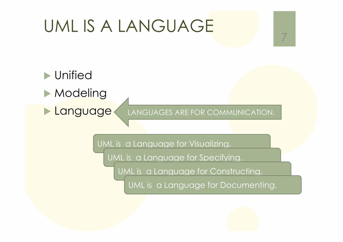
UML IS A LANGUAGE
� Unified
� Modeling
� Language
7
LANGUAGES ARE FOR COMMUNICATION.
UML is a Language for Visualizing.
UML is a Language for Specifying.
UML is a Language for Constructing.
UML is a Language for Documenting.
SPECS
� specification = design documents
� Specs are for:
1. Design a system
2. communication
8
MODELING
What is a Model?
� A model is a simplification of reality.
Why do we model?
� We build models so that we can better understand the system we are developing.
9
Principles of Modeling
First
� The choice of what models to create has a deep influence on how a problem is attacked and how to solution is shaped.
Second
� Every model may be expressed at different levels of precision.
Third
� The best models are connected to reality.
Fourth
� No single model or view is sufficient.
10
What Is the UML?
� The Unified Modeling
Language (UML) is a family of
graphical notations, backed
by single meta-model, that
help in describing and
designing object-oriented OO
style software systems.
11
http://www.uml.org/
UML is de-facto standard
� The Unified Modeling Language (UML) has quickly becomethe de-facto standard for building Object-Oriented software.
12
UML is a standard
� Unified Modeling Language (UML) is a
standardized (ISO/IEC 19501:2005),
general-purpose modeling language in
the field of software engineering.
� The UML is a relatively open standard,
controlled by the Object Management
Group (OMG),
an open consortium of companies.
� The OMG was formed to build standards the
support interoperability, specially interoperability
of object-oriented systems
13http://www.omg.org/
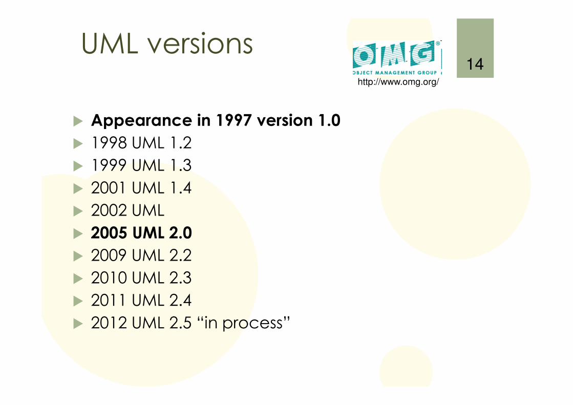
UML versions
� Appearance in 1997 version 1.0
� 1998 UML 1.2
� 1999 UML 1.3
� 2001 UML 1.4
� 2002 UML
� 2005 UML 2.0
� 2009 UML 2.2
� 2010 UML 2.3
� 2011 UML 2.4
� 2012 UML 2.5 “in process”
14http://www.omg.org/
15
For what?
� Unified Modeling Language (UML) combines techniques from:
� data modeling (entity relationship diagrams),
� business modeling (work flows),
� object modeling,
� and component modeling.
� It can be used with all processes, throughout the software development life cycle, and across different implementation technologies.
16
What UML is NOT!
� not a development method
� not a process
� not a programming environment
� not a programming language (yet)
� not ”a silver bullet”
17
USE OF UML
18
Ways of using the UML
� There has been (and there is still) long and difficult discussions how the UML should be used…
� three modes using UML:
� sketch
� blueprint
� programming language
19
1) UML as sketch
� developers use the UML to help communicate some aspects of a system
� forward-engineering
� UML diagrams before coding
� reverse-engineering
� UML diagrams after coding
� pretty informal and dynamic, needs only lightweight drawing tools
� emphasis is on selective communication rather than complete specification
20
2) UML as blueprint
� UML as blueprint is about completeness
� blueprints are developed by a designer, gives a detailed design for a programmer
� more detailed, very specific from all details to a particular area
� require much more sophisticated tools -> CASE-tools
� sketches are more explorative, blueprints are more definetive
21
3) UML as programming language
� many CASE tools do some form of code generation
� can reach the point at which all the system can be specified in the UML -> UML as programming language
� demands particularly sophisticated tooling
� forward/reverse engineering don’t make any sense for this mode, because UML and source code are same thing
22
Perspectives of the UML
� Software perspective
� the elements of the UML map pretty directly to elements in a software system
� Conceptual perspective
� the UML represents a description of the concepts of a domain study
� we are more building a vocabulary to talk about a particular domain
23
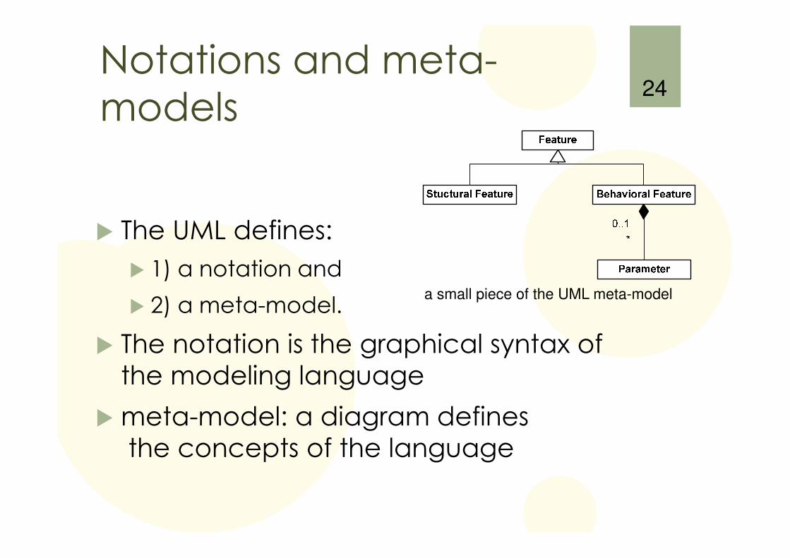
Notations and meta-models
� The UML defines:
� 1) a notation and
� 2) a meta-model.
� The notation is the graphical syntax of the modeling language
� meta-model: a diagram definesthe concepts of the language
24
a small piece of the UML meta-model
UML Diagrams
25
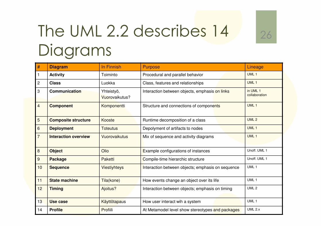
The UML 2.2 describes 14 Diagrams# Diagram In Finnish Purpose Lineage
1 Activity Toiminto Procedural and parallel behavior UML 1
2 Class Luokka Class, features and relationships UML 1
3 Communication Yhteistyö,
Vuorovaikutus?
Interaction between objects, emphasis on links in UML 1
collaboration
4 Component Komponentti Structure and connections of components UML 1
5 Composite structure Kooste Runtime decomposition of a class UML 2
6 Deployment Toteutus Depolyment of artifacts to nodes UML 1
7 Interaction overview Vuorovaikutus Mix of sequence and activity diagrams UML 1
8 Object Olio Example configurations of instances Unoff. UML 1
9 Package Paketti Compile-time hierarchic structure Unoff. UML 1
10 Sequence Viestiyhteys Interaction between objects; emphasis on sequence UML 1
11 State machine Tila(kone) How events change an object over its life UML 1
12 Timing Ajoitus? Interaction between objects; emphasis on timing UML 2
13 Use case Käyttötapaus How user interact wih a system UML 1
14 Profile Profiili At Metamodel level show stereotypes and packages UML 2.x
26

Classification of UML Diagram types
27
Profile Diagram
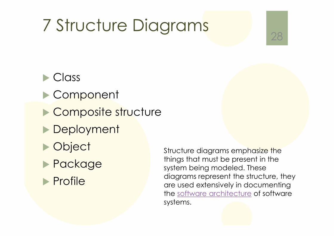
7 Structure Diagrams
� Class
� Component
� Composite structure
� Deployment
� Object
� Package
� Profile
28
Structure diagrams emphasize the things that must be present in the system being modeled. These diagrams represent the structure, they are used extensively in documenting the software architecture of software systems.
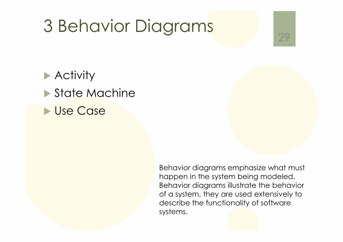
3 Behavior Diagrams
� Activity
� State Machine
� Use Case
29
Behavior diagrams emphasize what must happen in the system being modeled. Behavior diagrams illustrate the behavior of a system, they are used extensively to describe the functionality of software systems.
4 Interaction Diagrams
� Communication
� Interaction Overview
� Sequence
� Timing
30
Interaction diagrams, a subset of behavior diagrams, emphasize the flow of control and data among the things in the system being modeled
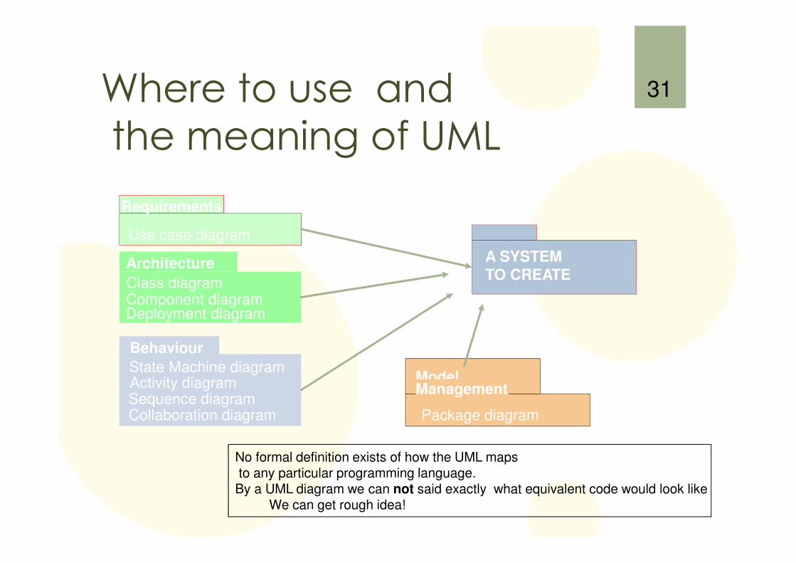
Where to use and the meaning of UML
31
A SYSTEM
TO CREATE
Requirements
Use case diagram
Behaviour
Sequence diagram
State Machine diagramActivity diagram
Collaboration diagram
ModelManagement
Package diagram
Architecture
Class diagramComponent diagramDeployment diagram
No formal definition exists of how the UML mapsto any particular programming language.By a UML diagram we can not said exactly what equivalent code would look like
We can get rough idea!
UML is Not Enough
� UML provides various diagrams that help to define an application, but it is NOT complete list of all useful diagrams that we might want to use
� Missing:
� a screen flow diagram,
� decision tables, etc
� �Don’t hesitate to use a non-UML diagram if no UML diagram suits your purpose.
32
Where to start?
� first:
� the basic form of class diagram (structure)
� the sequence diagram (behavior)
� later:
� more advanced class diagram notation
� other behavior diagrams
� other structure diagrams
33
Chapter 2: Development Process
34
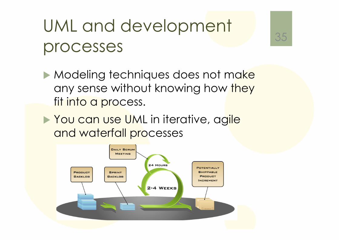
UML and development processes
� Modeling techniques does not make any sense without knowing how they fit into a process.
� You can use UML in iterative, agile and waterfall processes
35
My Three Favorites (and most used Diagrams)
�Use Case
�Class
�Sequence
36
Chapter 3: Class Diagrams / The EssentialsTHE MOST USED DIAGRAM
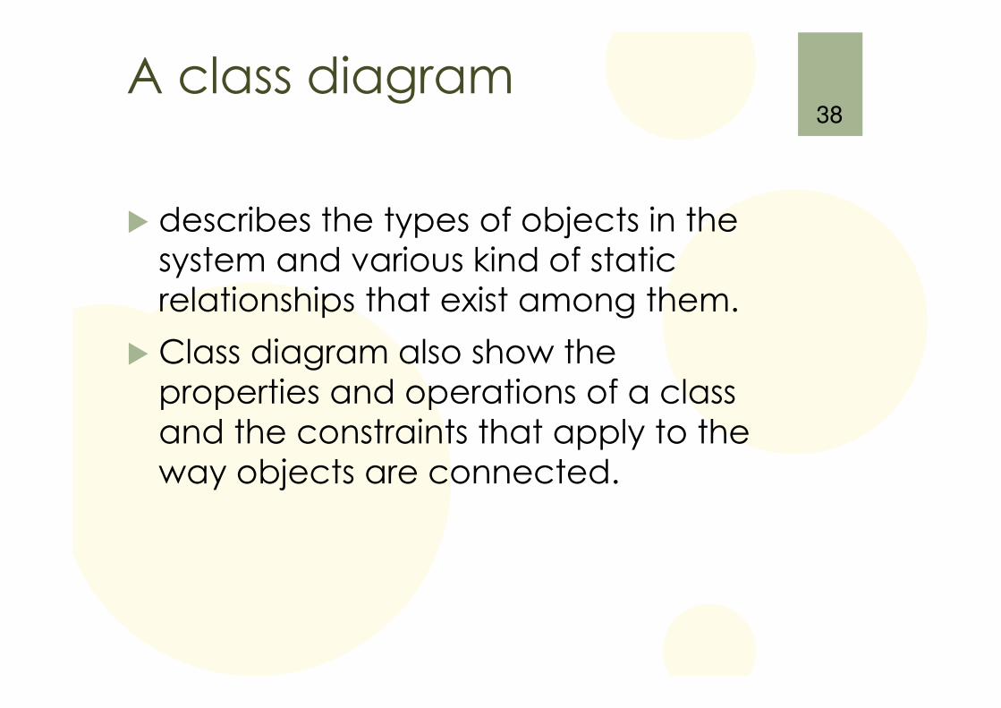
A class diagram
� describes the types of objects in the system and various kind of static relationships that exist among them.
� Class diagram also show the properties and operations of a class and the constraints that apply to the way objects are connected.
38
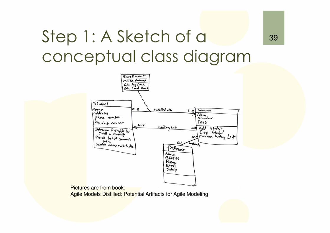
Step 1: A Sketch of a conceptual class diagram
39
Pictures are from book: Agile Models Distilled: Potential Artifacts for Agile Modeling
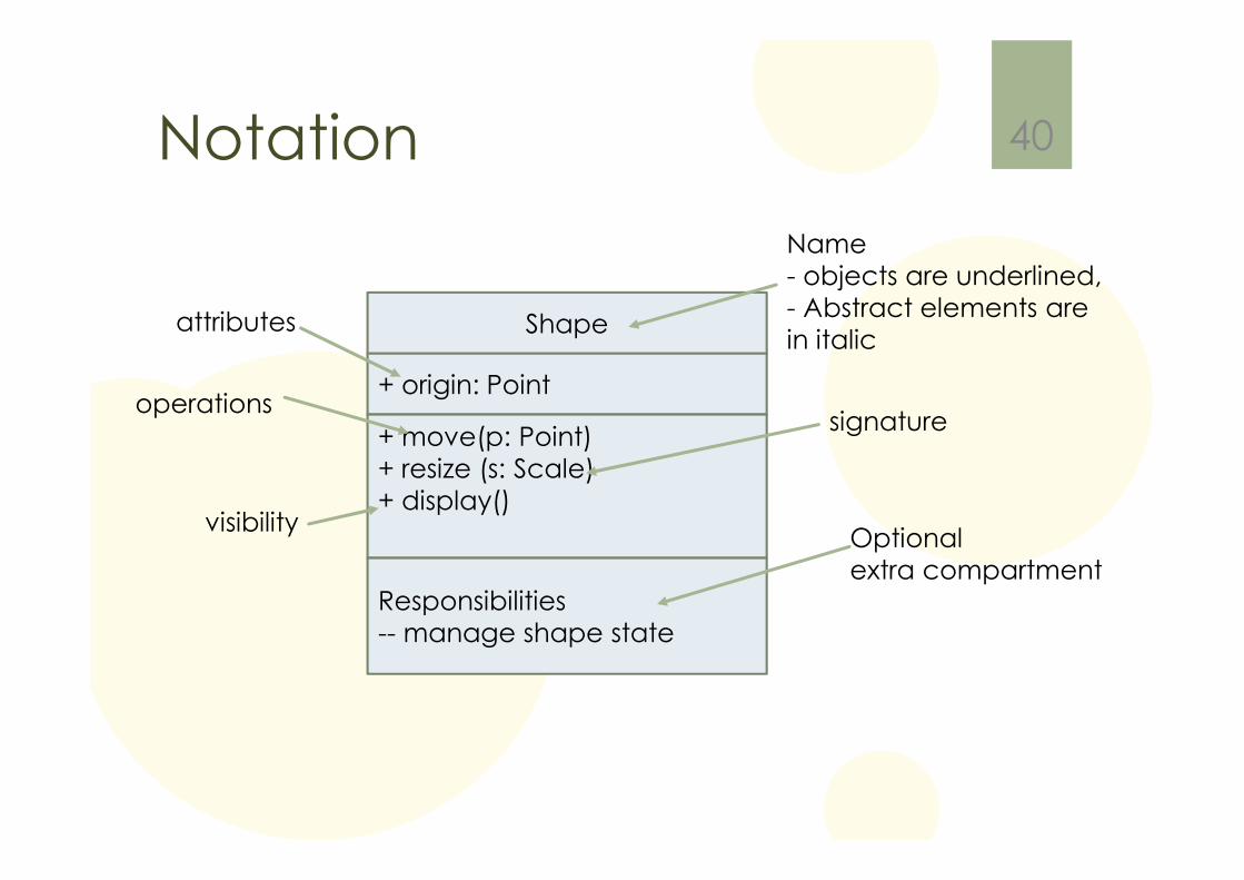
Notation 40
Shape
+ origin: Point
+ move(p: Point)+ resize (s: Scale)+ display()
Name- objects are underlined,- Abstract elements are in italic
attributes
operations
visibility
signature
Responsibilities-- manage shape state
Optionalextra compartment
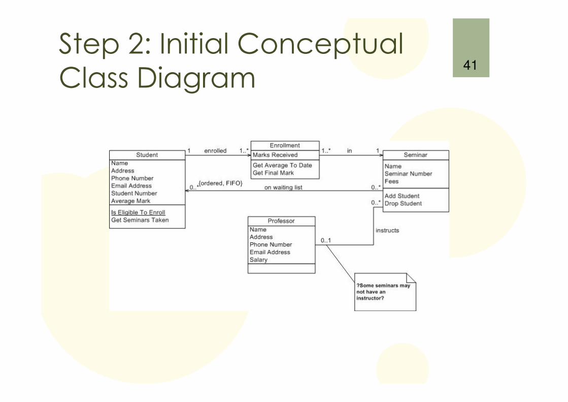
Step 2: Initial Conceptual Class Diagram
41
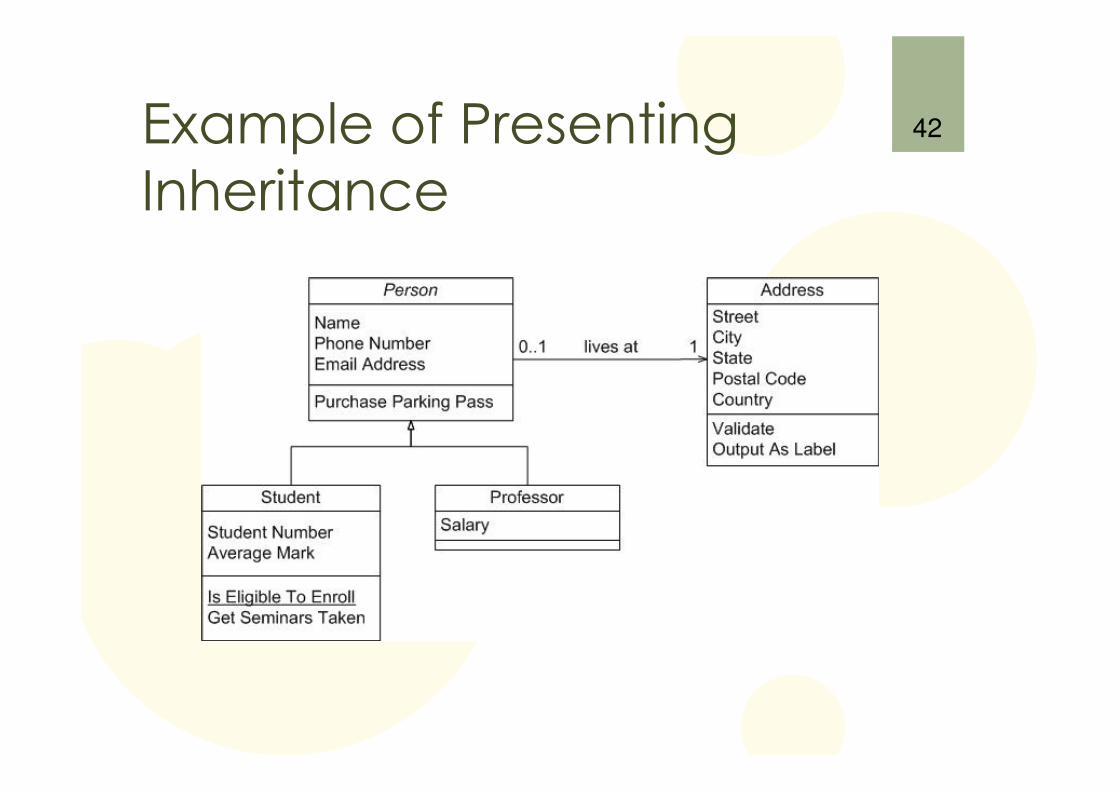
Example of Presenting Inheritance
42
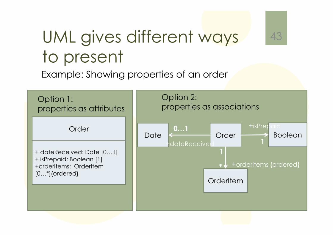
UML gives different ways to present
43
Option 1:properties as attributes
Order
+ dateReceived: Date [0…1]+ isPrepaid: Boolean [1]+orderItems: OrderItem[0…*]{ordered}
Option 2:properties as associations
Example: Showing properties of an order
Order BooleanDate
OrderItem
*
1
0…1
1
+isPrepaid
+dateReceived
+orderItems {ordered}
Chapter 4: Sequence DiagramsINTERACTION DIAGRAMS DESCRIBES HOW GROUPS OF OBJECTS COLLABORATE IN SOME BEHAVIOR (NOT ALL).
44
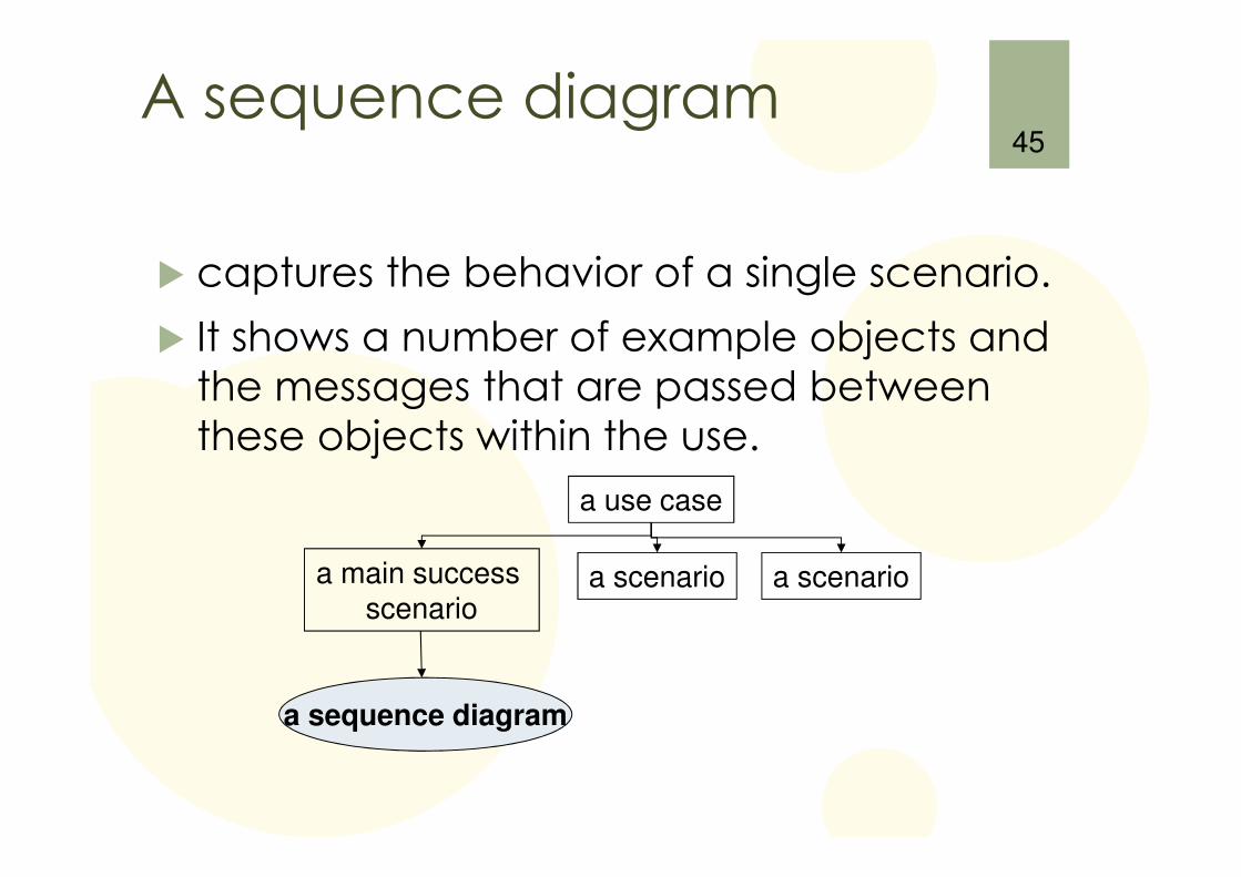
A sequence diagram
� captures the behavior of a single scenario.
� It shows a number of example objects and the messages that are passed between these objects within the use.
45
a scenario
a use case
a main success scenario
a scenario
a sequence diagram
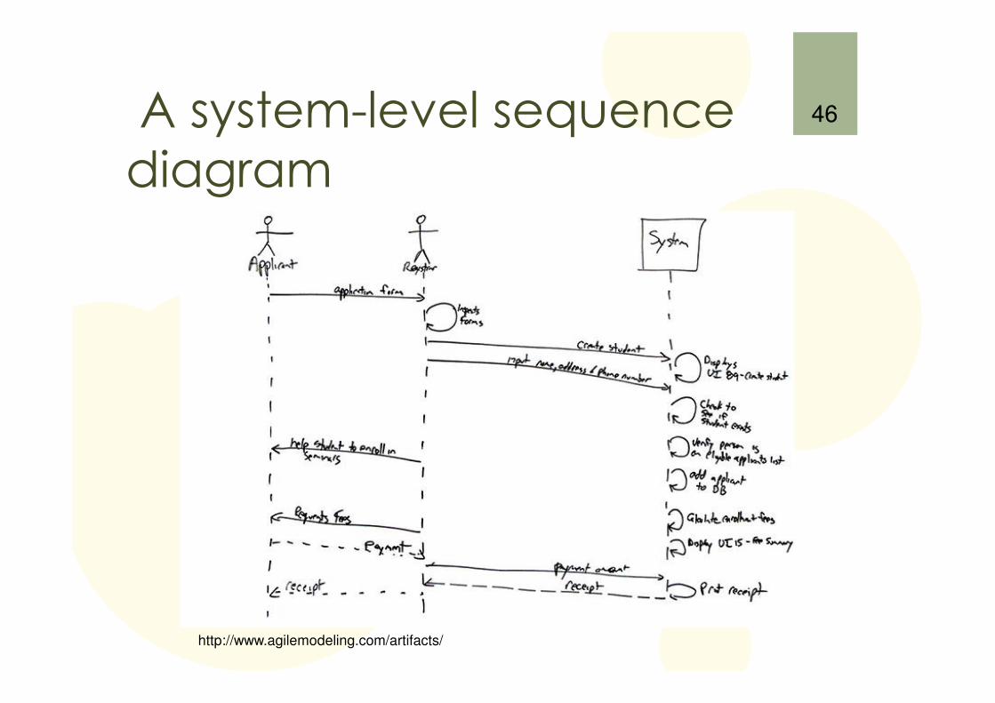
A system-level sequence diagram
46
http://www.agilemodeling.com/artifacts/
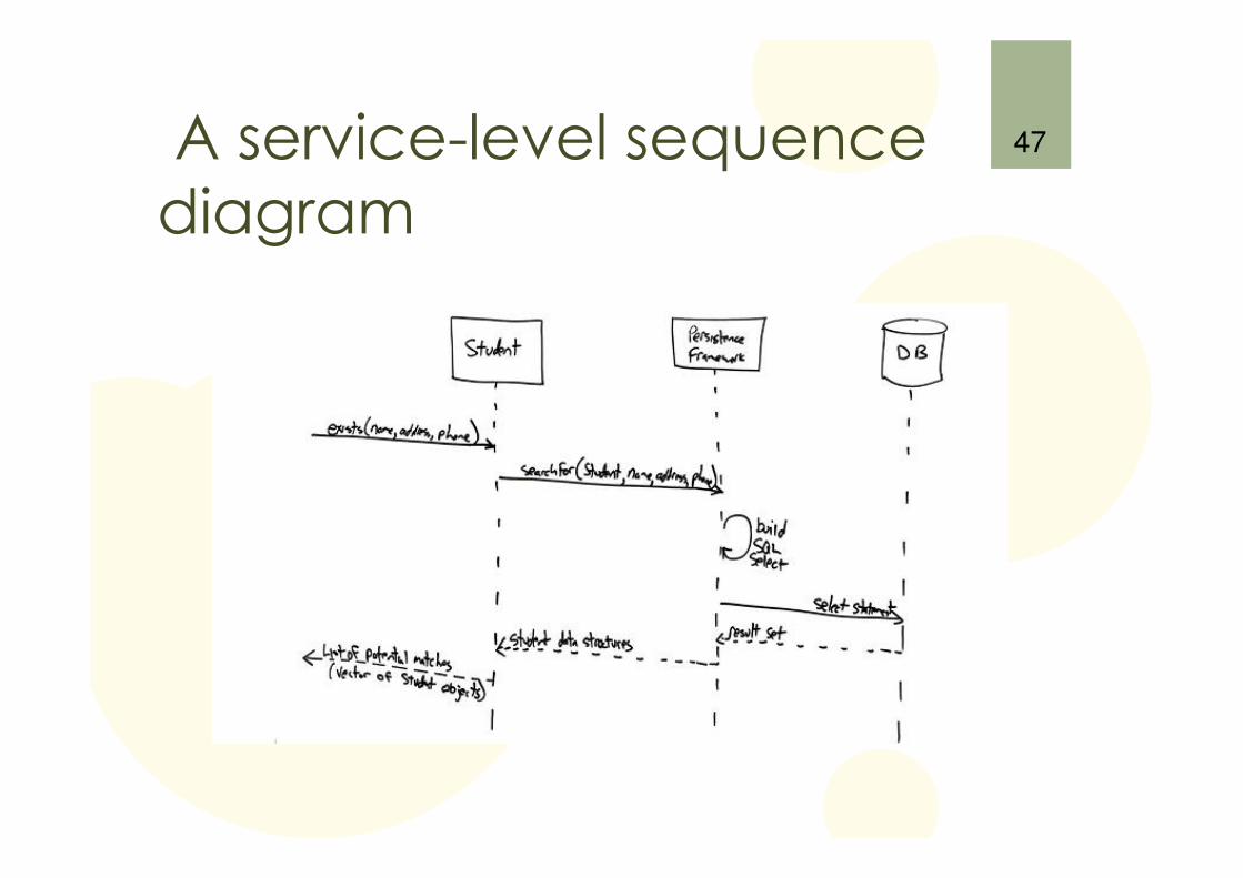
A service-level sequence diagram
47
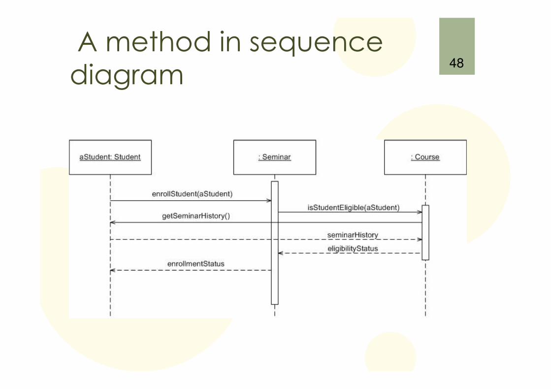
A method in sequence diagram
48
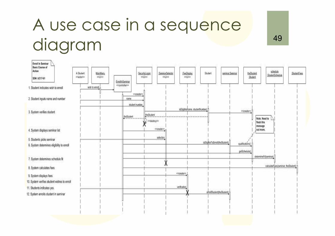
A use case in a sequence diagram
49
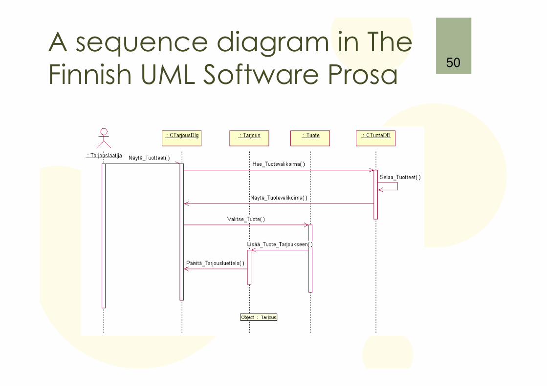
A sequence diagram in TheFinnish UML Software Prosa
50
Chapter 5: Class Diagrams / Advanced Concepts
51
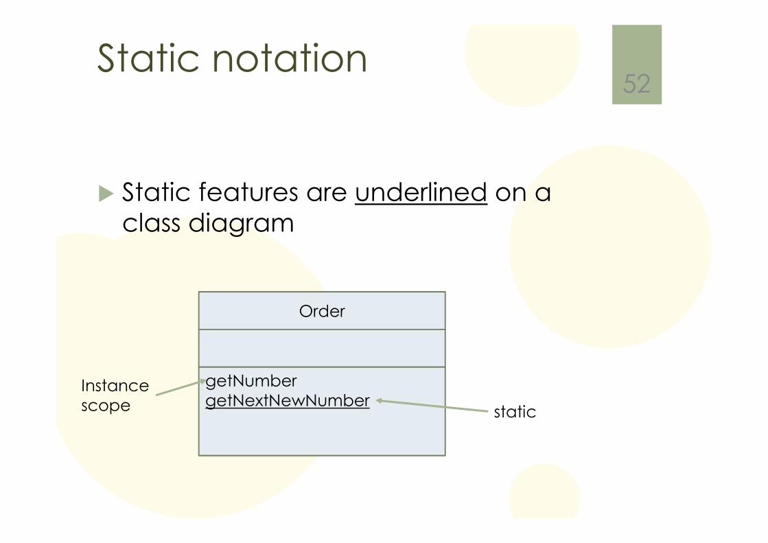
Static notation
� Static features are underlined on a class diagram
52
Order
getNumbergetNextNewNumber
Instancescope static
Chapter 6: Object Diagrams
53
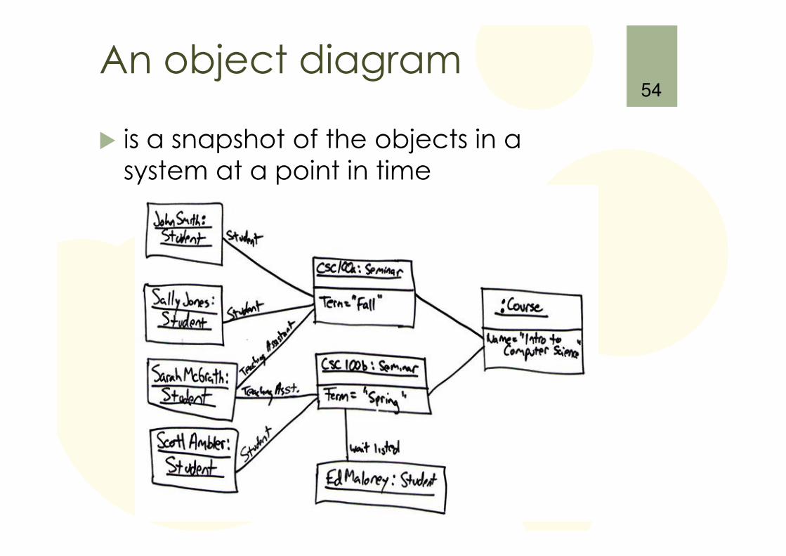
An object diagram
� is a snapshot of the objects in a system at a point in time
54
Chapter 7: Package Diagrams
55
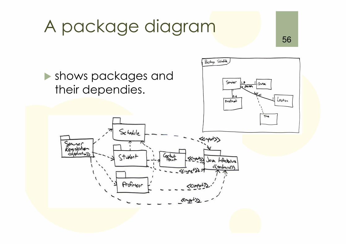
A package diagram
� shows packages andtheir dependies.
56
Chapter 8: Deployment Diagrams
57
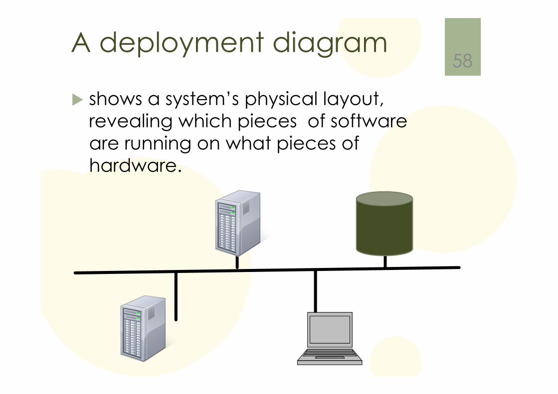
A deployment diagram
� shows a system’s physical layout, revealing which pieces of software are running on what pieces of hardware.
58
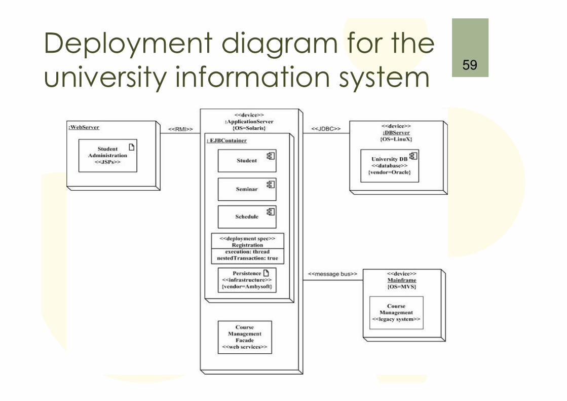
Deployment diagram for the university information system
59
Chapter 9: Use Cases
Where and when to use
� use cases are capturing the functional requirements of a system
� describes the typical interaction between the users of a system and the system itself
� an use case diagram itself it is a good start, normally we need written use case stories also
61
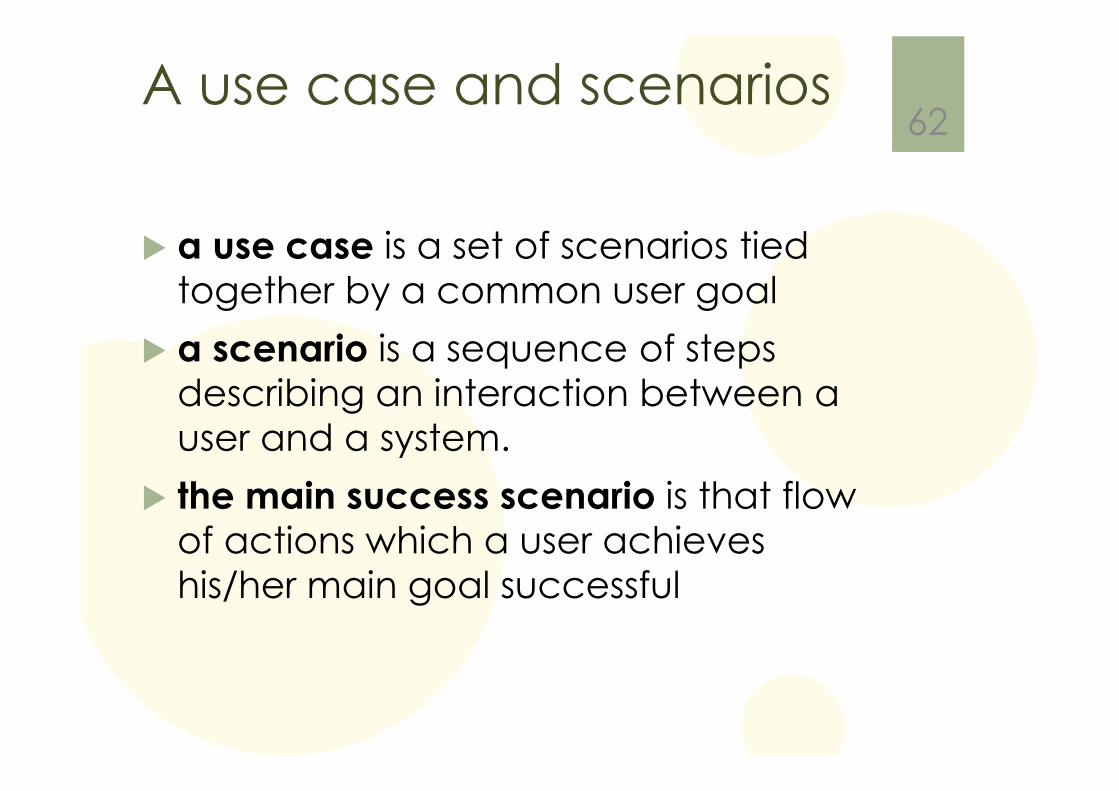
A use case and scenarios
� a use case is a set of scenarios tied together by a common user goal
� a scenario is a sequence of steps describing an interaction between a user and a system.
� the main success scenario is that flow of actions which a user achieves his/her main goal successful
62
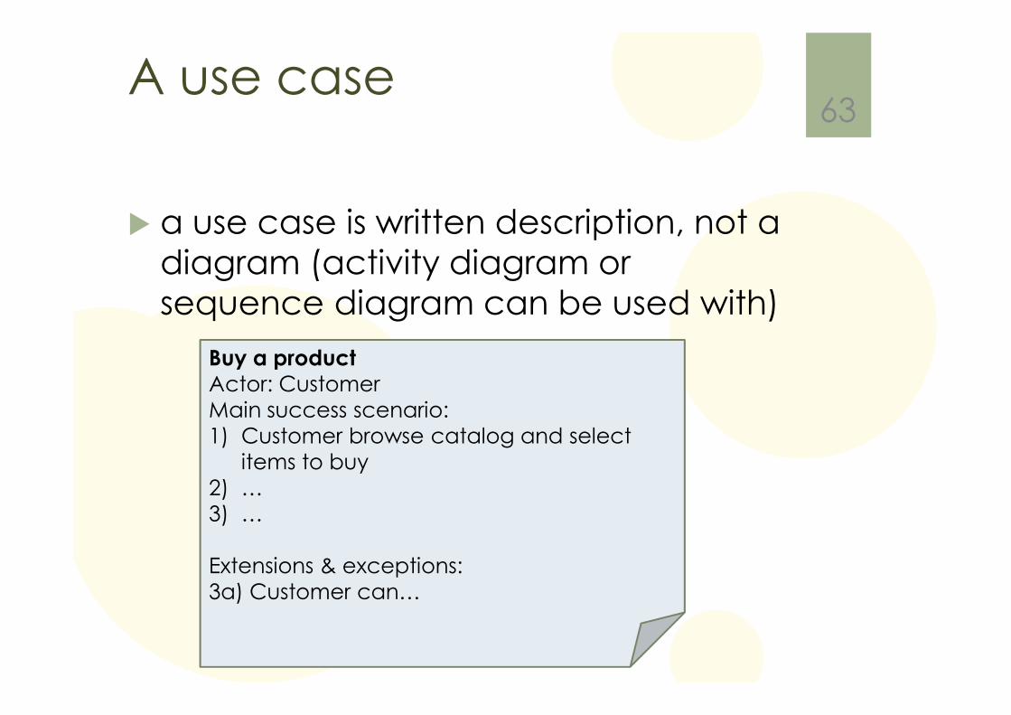
A use case
� a use case is written description, not a diagram (activity diagram or sequence diagram can be used with)
63
Buy a product
Actor: CustomerMain success scenario:1) Customer browse catalog and select
items to buy2) …3) …
Extensions & exceptions:3a) Customer can…
Different Use Case
� System use cases
� Business use cases
� Mis use cases
64
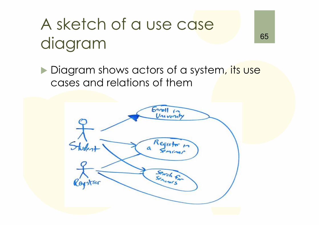
A sketch of a use case diagram
� Diagram shows actors of a system, its use cases and relations of them
65
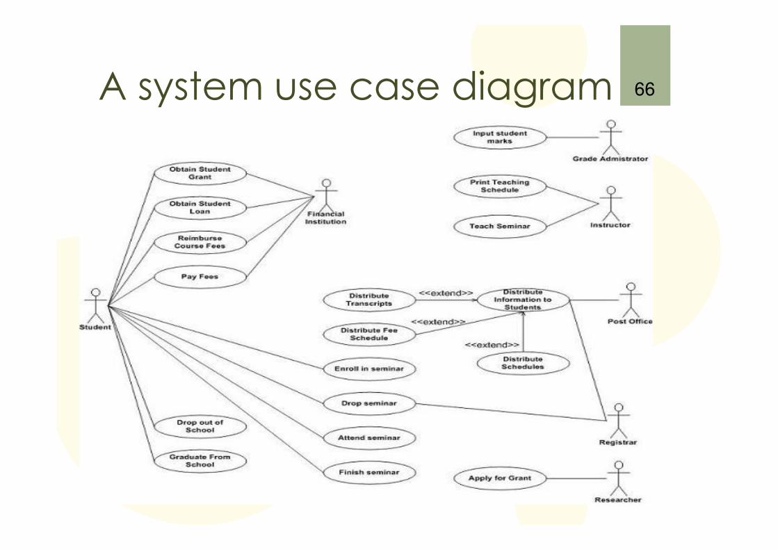
A system use case diagram 66
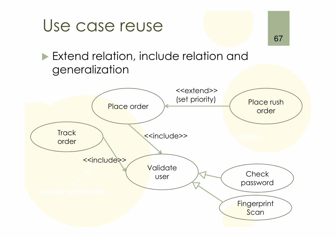
Use case reuse
� Extend relation, include relation and generalization
67
extension
generalization
include relationship
Place order
Validateuser
Trackorder
Checkpassword
FingerprintScan
Place rushorder
<<extend>>(set priority)
<<include>>
<<include>>
Chapter 10: State Machine Diagrams
68
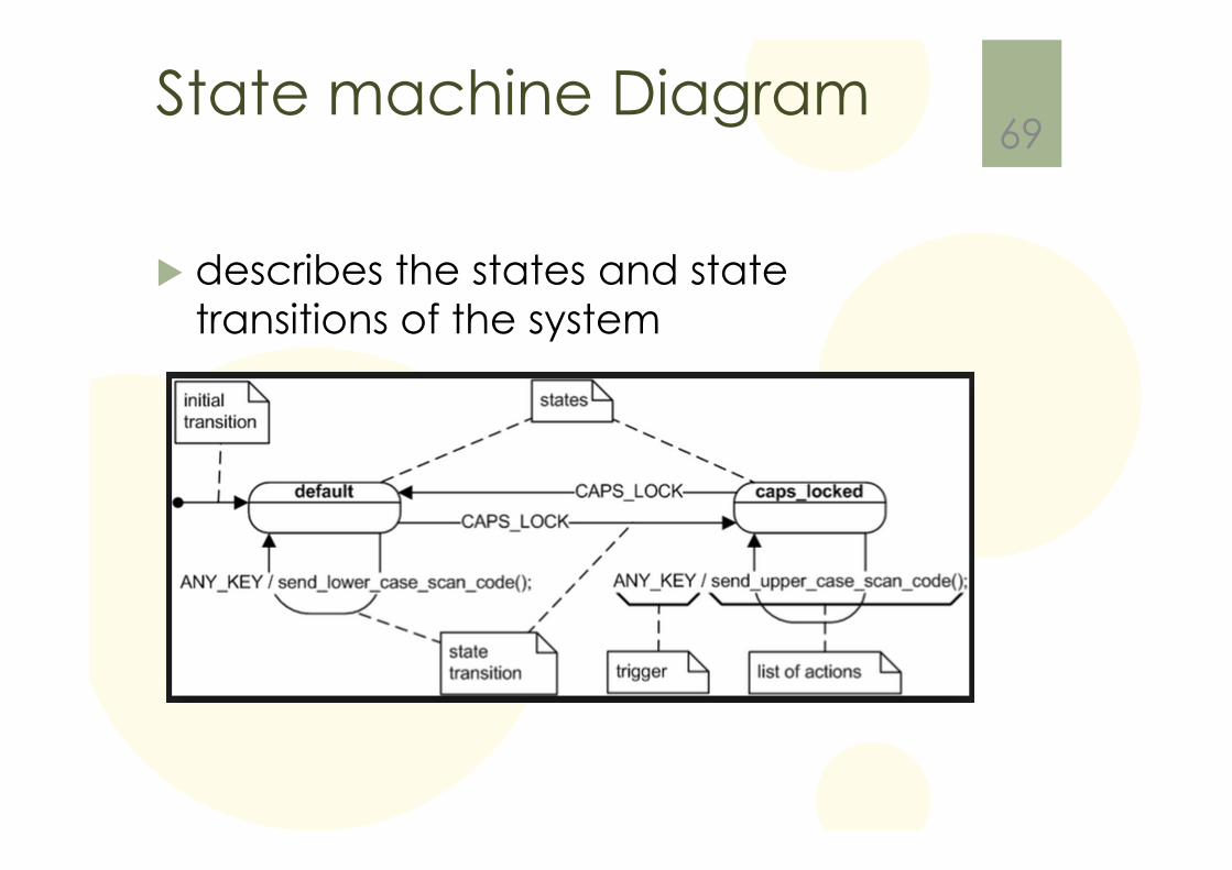
State machine Diagram
� describes the states and state transitions of the system
69
Chapter 11: Activity Diagrams
70
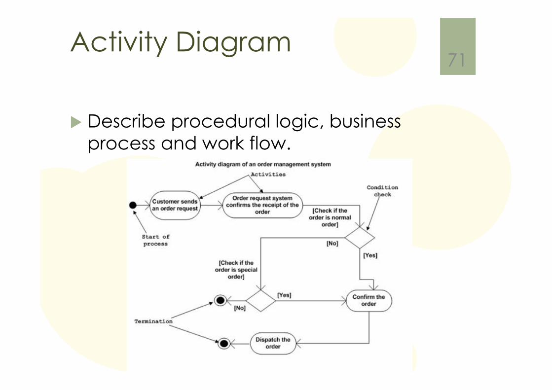
Activity Diagram
� Describe procedural logic, business process and work flow.
71
Chapter 12: CommunicationDiagrams
72
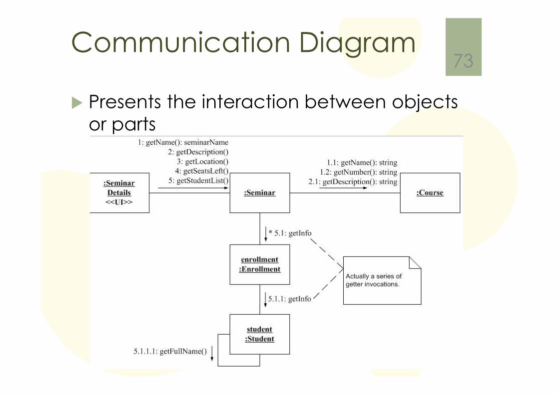
Communication Diagram
� Presents the interaction between objects or parts
73