umm al-qura university department of civil & structural engineering
DESCRIPTION
Design of reinforced concrete II Design of Flat Slab Floors Lecture (3). Umm Al-Qura University Department of Civil & Structural Engineering. Flat Slab Floors. A Flat slab floor is supported directly by columns without the use of beams. - PowerPoint PPT PresentationTRANSCRIPT
Umm Al-Qura University
Department of Civil & Structural Engineering
1
Design of reinforced concrete II
Design of Flat Slab Floors
Lecture (3)

2
Flat Slab Floors
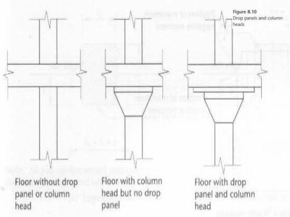
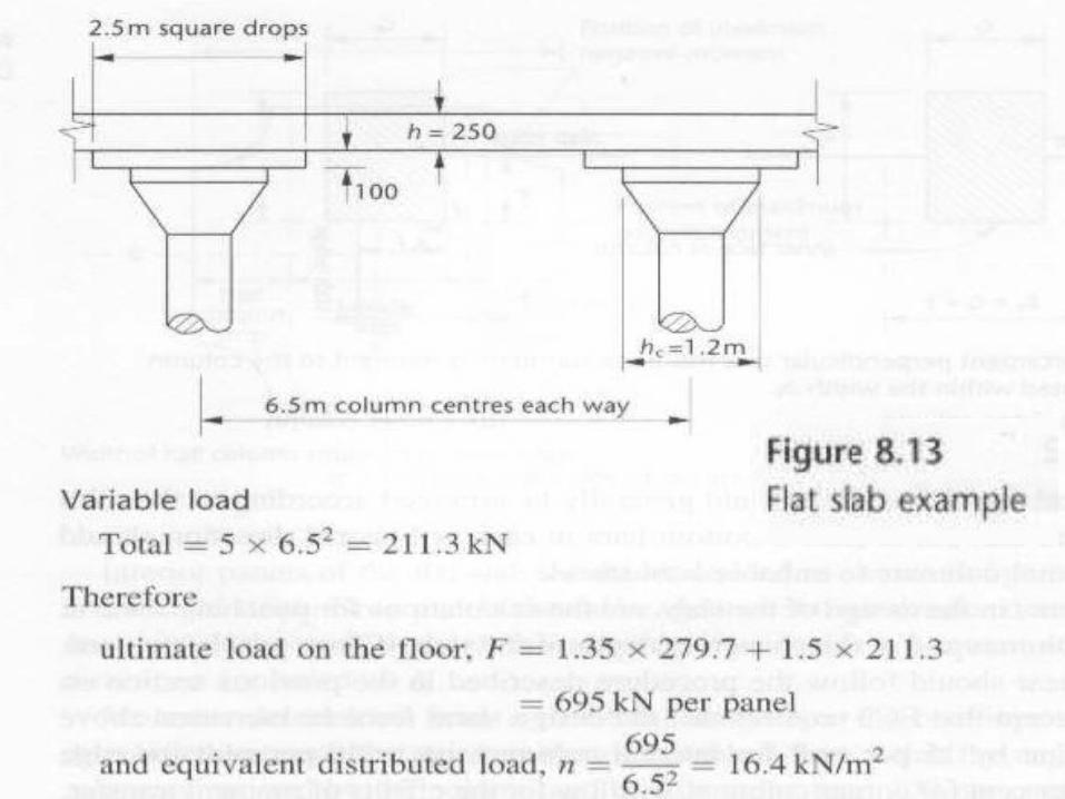
• A Flat slab floor is supported directly by columns without the use of beams.• The slab may be with constant thickness or in the area of the column it may thickened as a drop panel.• The column may also be constant section or it may be flared to form a column head or capital, see Fig 8.10• The drop panels are effective in:
1. Reducing the shear stresses.2. Provide an increased moment resistance.
3
4
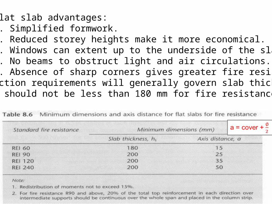
• The flat slab advantages: 1. Simplified formwork. 2. Reduced storey heights make it more economical. 3. Windows can extent up to the underside of the slab. 4. No beams to obstruct light and air circulations. 5. Absence of sharp corners gives greater fire resistance.• Deflection requirements will generally govern slab thickness which should not be less than 180 mm for fire resistance.

5
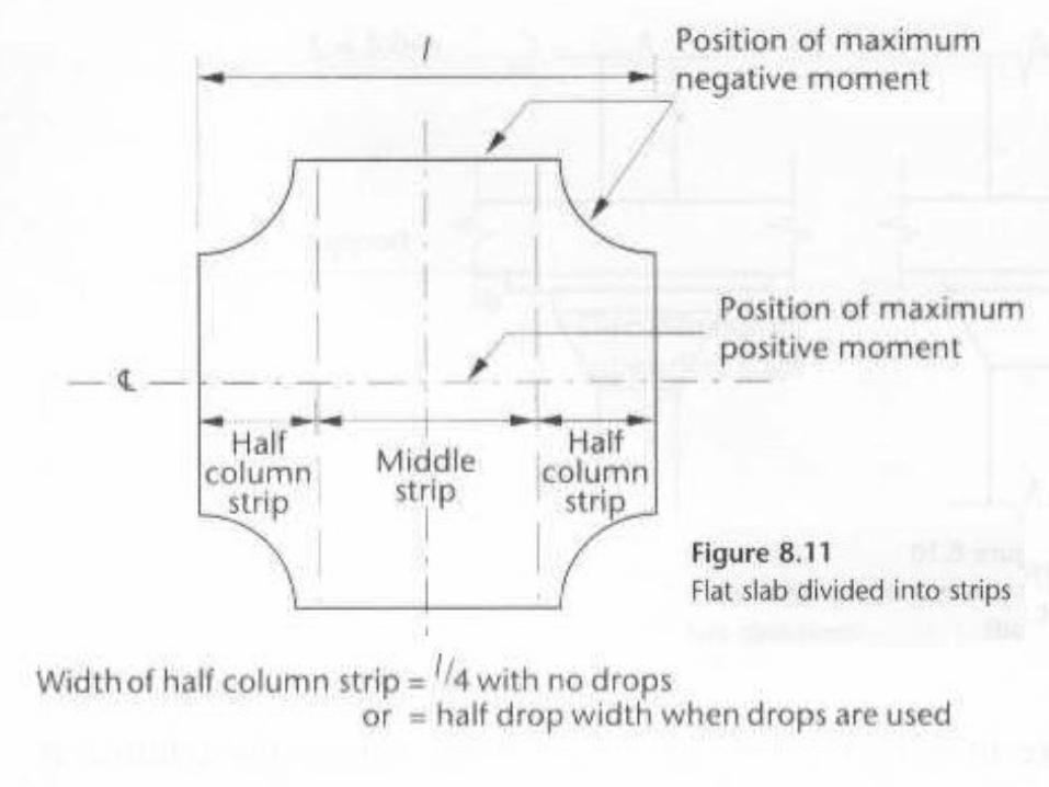
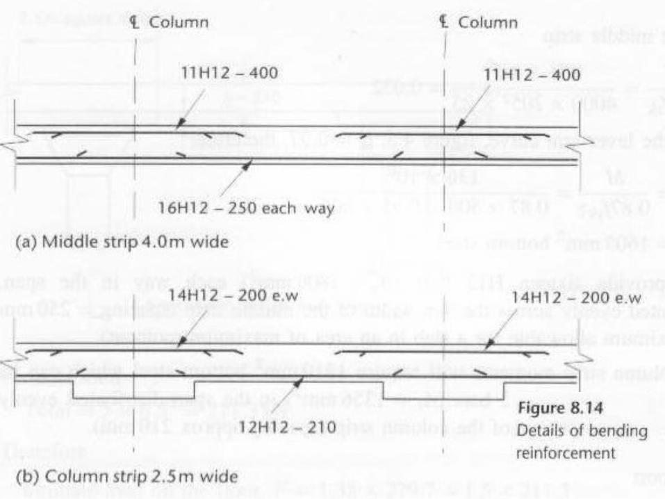
• Interior panels of the flat slab should be divided as shown in figure 8.11 into:
1. Column strip2. Middle strip
• Drop panels should be ignored if their smaller dimension is less than one third of the smaller panel dimension lx.•Moments are distributed between the strips as shown in table 8.7. •

6
• If the column strip is narrower because of drops, the moment resisted by the column and middle strips should be adjusted proportionally as illustrated in example 8.7.
7
8
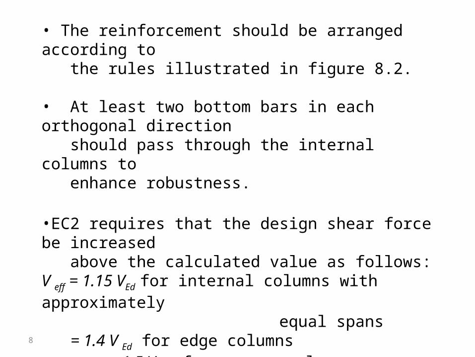
• The reinforcement should be arranged according to the rules illustrated in figure 8.2.
• At least two bottom bars in each orthogonal direction should pass through the internal columns to enhance robustness.
•EC2 requires that the design shear force be increased above the calculated value as follows:V eff = 1.15 VEd for internal columns with approximately equal spans = 1.4 V Ed for edge columns = 1.5 VEd for corner columns
9
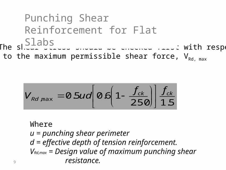
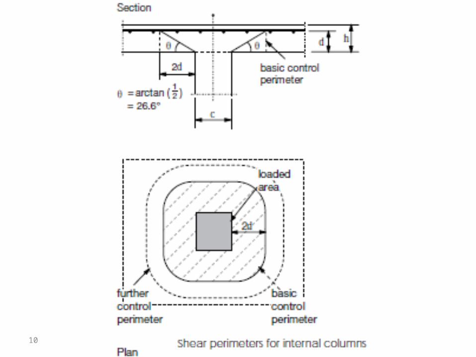
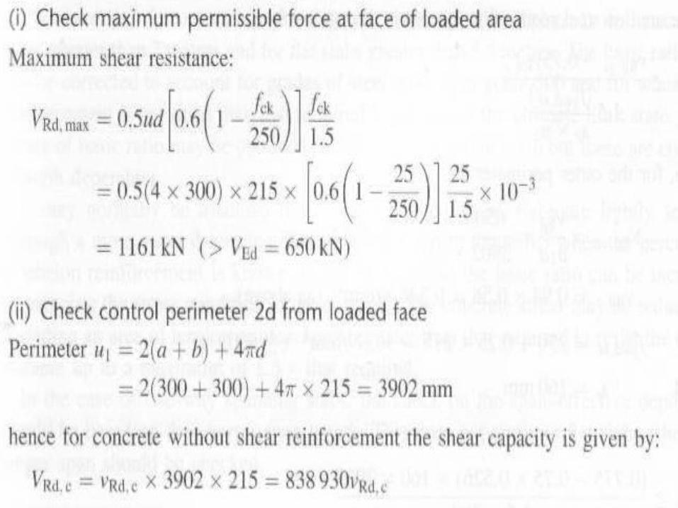
• The shear stress should be checked first with respect to the maximum permissible shear force, VRd, max
5.125016.05.0max,
ckckRd
ffudV
Whereu = punching shear perimeter d = effective depth of tension reinforcement.VRd,max = Design value of maximum punching shear resistance.
Punching Shear Reinforcement for Flat Slabs
10

11
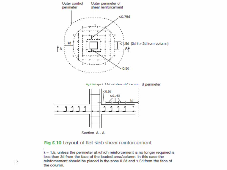
• The reinforcement should be provided in at least two perimeters of links. • The spacing of link perimeters (see the figure 5.10) should not exceed 0.75d.
• The spacing of link legs around a perimeter should not exceed 1.5d within the basic control perimeter (2d from the column face) .
• And should not exceed 2d for perimeters outside the basic control perimeter where that part of the perimeter is assumed to contribute to the shear capacity (see Figure 5.10).
12
13
14
15
16
17

18

19
20
21
22

23
24
25
26