umts basic principles
DESCRIPTION
this file contain basic prenciples about umts (3G)TRANSCRIPT

Huawei Confidential. All Rights Reserved
Introduction to UMTS
ISSUE 1.0

2 Internal Use
objectobject
Upon completion of this course, you will be able to:
Understand the history of 3G mobile communications
Understand the UMTS network architecture and 3GPP different releases
Understand the UMTS network services
Understand the basic principles of UTRAN

3 Internal Use
References References
TS 21.102 3rd Generation Mobile System Release 4 Specifications
TS 21.103 3rd Generation Mobile System Release 5 Specifications
Huawei’s UMTS RAN protocols and signaling analysis document

4 Internal Use
Part 1 Part 1 Introduction to UMTS
Part 2 UTRAN basic principles
Part 3 ATM basic principles
5 Internal Use
Part 1 Introduction to UMTS Section 1 History of 3G
Section 2 UMTS network structure
Section 3 UMTS network services

6 Internal Use
Development of Mobile communication Development of Mobile communication
AMPS = Advanced Mobile phone service GSM=Global system for Mobile Communications
TACS=Total Access Communications Systems D-AMPS=Digital-AMPS
NMT=Nordic Mobile Telephone PDC=personal digital cellular
1st Generation 1980s (analog)
2nd Generation 1990s (digital)
3rd Generation current (digital)
AMPS
Analog to DigitalTACS
NMT
OTHERS
GSM
CDMA IS95
D-AMPS
PDC
WCDMAFDD
CDMA 2000
WCDMA TDD
Voice to Broadband

7 Internal Use
History of 3GHistory of 3G
At 1985 : ITU started the process of defining the standard for third generation systems, referred to as International Mobile Telecommunications 2000 (IMT-2000)
Some of the features that IMT-2000 3G network must include
1-Circuit and packet oriented services
2-Simultaneous multiple services
3-Symmetrical and Asymmetrical services
4-Migration path from 2G systems
5-Supporting Multimedia services Car speed environment: 144kbps Walk speed environment: 384kbps Indoor environment: 2048kbps
1992: 230MHz spectrum was allocated in 2GHz band (WARC92)
8 Internal Use
History of 3GHistory of 3G
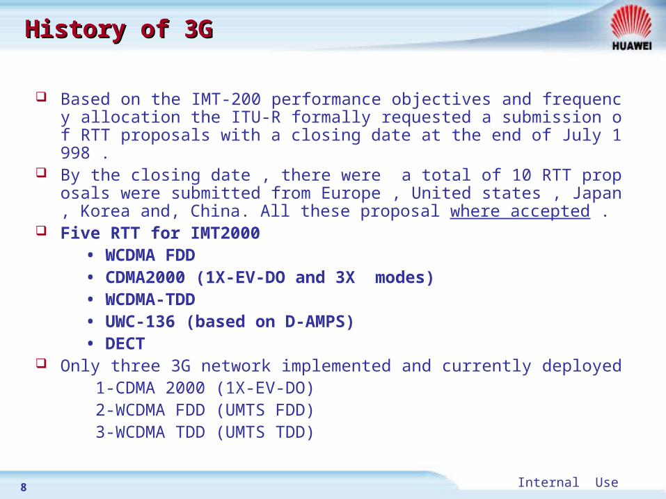
Based on the IMT-200 performance objectives and frequency allocation the ITU-R formally requested a submission of RTT proposals with a closing date at the end of July 1998 .
By the closing date , there were a total of 10 RTT proposals were submitted from Europe , United states , Japan , Korea and, China. All these proposal where accepted .
Five RTT for IMT2000 • WCDMA FDD • CDMA2000 (1X-EV-DO and 3X modes) • WCDMA-TDD • UWC-136 (based on D-AMPS) • DECT Only three 3G network implemented and currently deployed 1-CDMA 2000 (1X-EV-DO) 2-WCDMA FDD (UMTS FDD) 3-WCDMA TDD (UMTS TDD)

9 Internal Use
3G standardization organizations 3G standardization organizations
Standardization organizations such as 3GPP, 3GPP2 were established
3G system
WCDMA
3GPP
FDD/TDD mode
CDMA2000
3GPP2

10 Internal Use
Frequency allocation for IMT2000Frequency allocation for IMT2000
USA
1800 1900 2000 2100 2200MHz
IMT-2000 IMT-2000
MSS
1980
2010 2025
MSS
21702110
21702110
MSSUMTS
2110
IMT-2000 MSS
2170
IMT-2000 MSS PHS
1895 1918 1980 20252010
1850
193
0
1990
Unlicensed
MSS UMTSDECT
1880 20101980 2025
1885
PCS
2155
2025
IMT-2000 IMT-2000
IMT-2000
MSS (Reg.2)
MSS (Reg.2)
UMTS
WARC in 1992 230MHz in 2GHZ Band was allocated to IMT2000
MSS MSS
1900 1920
1910 2110 2150 2165
Reserve MSS
ITU
Japan
Europe/Australia
MSS: Mobile Satellite Service

11 Internal Use
Frequency allocation for IMT2000Frequency allocation for IMT2000 Additional (2nd of June, 2000)
IMT-2000
GSM(Current)
PDC(Current)
800 1000 1500 2500 MHz
960 1885 2690
2010
2110
2170
19801710806
2025
WRC2000 Conference has decided to allocate additional bands for IMT-2000,
800MHz, 1.8GHz, and 2.5GHz Band.
2000
880 960 1710 1990
: Additionally assigned for IMT-2000
810 958 1429 1513

12 Internal Use
UMTS FDD and TDDUMTS FDD and TDD
FDD (Frequency Division Duplex)
TDD (Time Division Duplex)
Base stationMobile Terminal
f 1: for Up Link
f 2: for Down Link
Base stationMobile Terminal
f 1: for Up & Down Link
Up Down
TS TS
TS: Time slot

13 Internal Use
Summary Summary
IMT-2000 is the ITU standard for 3G mobile communications three 3G networks are implemented and currently deployed
1-CDMA 2000 (1X-EV-DO)
2-WCDMA FDD (UMTS FDD)
3-WCDMA TDD (UMTS TDD) 3GPP is responsible for producing UMTS network standard specifications 3GPP2 is responsible for producing CDMA2000 network standard
specifications

14 Internal Use
Part 1 Introduction to UMTS Section 1 History of 3G
Section 2 UMTS network structure
Section 3 UMTS network services

15 Internal Use
3GPP R99 network Architecture3GPP R99 network Architecture

16 Internal Use
3GPP R99 network Architecture3GPP R99 network Architecture
Interoperability with GSM CS domain elements are able to handle 2G and 3G subscribers. Changes (upgrades) in MSC/VLR and HLR/AC/EIR. For example SGSN
2G responsible for mobility management (MM) for packet connections 3G MM divided between RNC and SGSN

17 Internal Use
3GPP R4 network Architecture3GPP R4 network Architecture

18 Internal Use
3GPP R4 network Architecture3GPP R4 network Architecture
The 3GPP R4 introduces separation of the connection, its control, and services for CS domain of CN.
Media Gateway (MGW): an element for maintaining the connection and performing switching function when required.
MSC server: an element controlling MGW and responsible for signaling Packet switched voice
The CS call is changed to the packet switched call in MGW.

19 Internal Use
Difference between R99 and R4Difference between R99 and R4
MSC
SCP HLR
MSC
RAN RAN RAN
TDMMSC Server
SCP HLR
RAN RAN RAN
ATM/IPMGW MGW
MSC ServerTUP/ISUP
Notes: PS domain structure remain unchanged
R99 R4
MAP Over TDM MAP Over TDM/IP
CS domain evolution
ATM/IP
ATM/IP/TDM

20 Internal Use
3GPP R5 network architecture3GPP R5 network architecture

21 Internal Use
3GPP R5 network architecture3GPP R5 network architecture
3GPP R5 introduces the High Speed Downlink Packet Access (HSDPA) The HSDPA scheme proposes to add an additional wideband downlink
shared channel that is optimized for very high-speed data transfer In HSDPA the coding and modulation scheme used are changed according
to air interface conditions Release 5 employs two modulation schemes, QPSK and 16QAM. Later
releases may introduce other schemes, such as 64QAM 3GPP R5 introduces a IP Multimedia subsystem (IMS)

22 Internal Use
SummarySummary
3GPP R99 is the first 3GPP specification for UMTS based on GSM NSS as a CN
R4 softswitch based CS Core network was introduced in 3GPP R4 HSDPA and IMS are introduced in 3GPP R5

23 Internal Use
Part 1 Introduction to UMTS Section 1 History of 3G
Section 2 UMTS network structure
Section 3 UMTS network services

24 Internal Use
QoS of Different ServicesQoS of Different Services
Time delay
Quality (BER)
background
conversational
streaming
interactive

25 Internal Use
UMTS services UMTS services
Conversational Services Speech service:
Real time conversational service require the low time delay from end to end , and the uplink and the downlink service bandwidth is symmetrical .
Adopt AMR ( adaptive multi rate ) technique (WCDMA).
– 12.2, 10.2, 7.95, 7.40, 6.70, 5.90, 5.15 and 4.75kbps.– The bit rate of AMR voice can be controlled by the RAN
according to the payload of air interface and the quality of voice service .
Video phone (WCDMA) The requirement of time delay is similar to the voice service The CS connection :adopt ITU-T Rec.H.324M (AMR-H.263) The PS connection :adopt IETF SIP or H.323

26 Internal Use
UMTS services UMTS services
Streaming Services (eg. Telemetry (monitoring) , Audio and Video streaming )
Interactive Services (eg. Web browsing , and online games )
Background Services (eg. Email , Fax , and SMS )

27 Internal Use
SummarySummary

28 Internal Use
Part 1 Part 1 Introduction to UMTS
Part 2 UTRAN basic principles
Part 3 ATM basic principles

29 Internal Use
Multiple Access TechniquesMultiple Access Techniques
Traffic channels: different users are assigned unique code and transmitted over the same frequency band, for example, WCDMA and CDMA2000
Traffic channels: different frequency bands are allocated to different users,for example, AMPS and TACS
Traffic channels: different time slots are allocated to different users, for example, DAMPS and GSM
FrequencyTime
Power
FrequencyTime
Power
FrequencyTime
Power
FDMA
TDMA
CDMA
User
User
User
User User
User

30 Internal Use
Multiple Access TechniquesMultiple Access Techniques
Defect1. Simple Implementation 1. Frequency Reuse
2. privacy
1. Need synchronized of frame
1. Reduction the interference
2. Diversity Hand-over
3. Privacy
1. Sophisticated power control for mobile
1.Privacy
Advantage
FDMA
TDMA
CDMA
AMPS, TACS
GSM, PDC
IS95,W-CDMA
Defect

31 Internal Use
Multiple Access TechniquesMultiple Access Techniques
FDMA/TDMA CDMA
Frequency is different in each sector.
Frequency is same.
Need for
frequency plan (Frequency ReuseFrequency Reuse)
No need for frequency plan
f1 f
6
f 5
f 2f
3f 4
f1
f 7
f 7
f 4
f 6f
7
f1
f 3f 4
f 6f
7f 2
f 5f 6f 2 f
2f 5 f
3
f1f 7
f 6
f 5
f 2
f 4
f1
f1
f 7
f1f
7
f1f1
f1 f
1f1
f1
f1
f1
f1
f1
f1
f1
f1
f1
f1
f1f1f1
f1
f1

32 Internal Use
DS-CDMA DS-CDMA
User-A
A
Code 1
User-B
B
Code 2
User-C
C
Code 3
User-A
A
Code 1
User-B
B
Code 2
User-C
C
Code 3
De-spreadingCode
Narrow BandSignal
Wide BandSignal
(Multiple Signal)Spreading DespreadingNarrow Band
Signal
CBA
(Receiver A)
(Receiver B)
(Receiver C)

33 Internal Use
Rake ReceiverRake Receiver
A B C
A B C
ABC
Rake

34 Internal Use
Rake receiverRake receiver
RXRX
Searcher Searcher Searcher Searcher
CombinerCombinerCombinerCombiner
CalculationCalculationCalculationCalculation
Combined Signal
RAKE ReceiverRAKE Receiver
Electric PowerElectricPower
Delay Profile
Delay Time
Multiple Signal 1Multiple Signal 2
Multiple Signal 3
Delay Time
Finger CircuitFinger CircuitFinger CircuitFinger Circuit
Finger CircuitFinger CircuitFinger CircuitFinger Circuit
Finger CircuitFinger CircuitFinger CircuitFinger Circuit
Output Power

35 Internal Use
WCDMA handover types
Soft Handover
UE is connected simultaneously to more than one base station (up to 3 sectors) using the same frequency
The UE receives the downlink transmissions of two or more base stations. For this purpose it has to employ one of its RAKE receiver fingers for each received signal.
in the uplink direction , the code channel of the mobile station is received from both base stations, but the received data is then routed to the RNC for combining
The RNC selects the better frame between the two possible candidates based on frame reliability indicator
36 Internal Use
WCDMA handover types
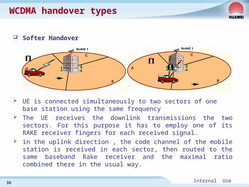
Softer Handover
UE is connected simultaneously to two sectors of one base station using the same frequency
The UE receives the downlink transmissions the two sectors. For this purpose it has to employ one of its RAKE receiver fingers for each received signal.
in the uplink direction , the code channel of the mobile station is received in each sector, then routed to the same baseband Rake receiver and the maximal ratio combined there in the usual way.

37 Internal Use
WCDMA handover types
Hard Handover
The UE stops transmission on one frequency before it moves to another frequency and starts transmitting again
During Hard Handover the used radio frequency (RF) of the UE changes

38 Internal Use
WCDMA handover types
Inter-system Handover Handover between two different radio access technologies Handover between UMTS FDD and GSM Handover between UMTS FDD and UMTS TDD

39 Internal Use
Spreading process in WCDMASpreading process in WCDMA
1st Step: Channelization Variable Rate Spreading ( According to user data rate)
2nd Step: Scrambling Code Fixed Rate Spreading (3,840 Kchips)
ChannelizationCode
ScramblingCode
3,840 KcpsCoding
&
Interleaving
Coding
&
Interleaving

40 Internal Use
Spreading process in WCDMASpreading process in WCDMA
Downlink (NodeB to UE )
Scrambling Code: Identifies cell (sector). Channelization Code: Identifies user channels in cell (Sector).
Scrambling Code A
Scrambling Code B
Scrambling Code C
ChannelizationCode 1
ChannelizationCode 2 Channelization
Code 3
ChannelizationCode 1 Channelization
Code 2
ChannelizationCode 2
ChannelizationCode 1

41 Internal Use
Spreading process in WCDMASpreading process in WCDMA
Up Link (UE to NodeB )
Scrambling Code: Identifies user terminal.
Channelization Code: Identifies channels in user terminal.
Scrambling Code A
Scrambling Code B
Scrambling Code C
ChannelizationCode 1
ChannelizationCode 2
ChannelizationCode 1
ChannelizationCode 1
42 Internal Use
Spreading process in WCDMASpreading process in WCDMA
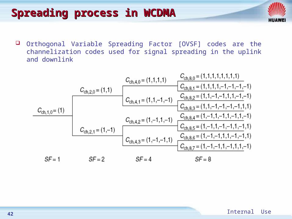
Orthogonal Variable Spreading Factor [OVSF] codes are the channelization codes used for signal spreading in the uplink and downlink

43 Internal Use
Spreading process in WCDMASpreading process in WCDMA
The code used for scrambling of the uplink Channels may be of either long or short type, There are 224 long and 224 short uplink scrambling codes. Uplink scrambling codes are assigned by higher layers.
For downlink physical channels, a total of 218-1 = 262,143 scrambling codes can be generated. Only scrambling codes k = 0, 1, …, 8191 are used.
In the downlink direction 512 of scrambling codes are used to identify the cells in the downlink so downlink planning is required

44 Internal Use
W-CDMA (IMT-DS) SpecificationW-CDMA (IMT-DS) Specification
Multiple access method DS-CDMA (DS: Direct Spread)
Duplexing methodFDD/TDD (Frequency Division Duplex/Time Division Duplex)
Inter-cell synchronization Asynchronous
Bandwidth 5 MHZ
Chip rate 3.84 Mcps
Carrier spacing Flexible with 100/200kHz carrier raster
Frame length Unit 10 ms
Data modulation Downlink: QPSK, Uplink: BPSK
Multi-rate concept Variable spreading factor and/or multi-code
Maximum data rate 2 Mbps (indoor)/384 kbps (mobile)
Channel codingConvolutional coding (R=1/3 or 1/2, K=9)Turbo code for High data rate
BPSK: Binary phase shift keying QPSK: Quadrature phase shift keying

45 Internal Use
UMTS FDD frequency allocations UMTS FDD frequency allocations
Operating Band UL FrequenciesUE transmit, Node B receive
DL frequenciesUE receive, Node B transmit
I 1920 – 1980 MHz 2110 –2170 MHz
II 1850 –1910 MHz 1930 –1990 MHz
III 1710-1785 MHz 1805-1880 MHz
IV 1710-1755 MHz 2110-2155 MHz
V 824 – 849 MHz 869-894 MHz
VI 830-840 MHz 875-885 MHz
Operating Band TX-RX frequency separation
I 190 MHz
II 80 MHz.
III 95 MHz.
IV 400 MHz
V 45 MHz
VI 45 MHz

46 Internal Use
SummarySummary
UMTS is based on DS-CDMA as a multiple access technique Rack receiver is used to combine signals and get benefits from Multipath
fading . Also it is used to combine signals in soft and softer handover cases Two types of Power control are used in UMTS , open and closed loop power
control Types of handover in UMTS
Soft handover Softer handover Hard handover Inter-system handover
Spreading process in WCDMA consists of two stages Channelization Scrambling
47 Internal Use
Part 1 Part 1 Introduction to UMTS
Part 2 UTRAN basic principles
Part 3 ATM basic principles

48 Internal Use
To provide a high-speed, low delay
multiplexing and switching network to any type of
user traffic, such as voice support, data,or video
applications.
Why do we need a new technology?Why do we need a new technology?

49 Internal Use
TraditionaTraditionall Switch Model’s Characteristic Switch Model’s Characteristic
Circuit Switching Data is sent from the same route, so time delay is fixed High-speed switching Fixed rate
Packet Switching Support multi-rate switching Take full advantage of bandwidth/waste of bandwidth Time delay is not fixed

50 Internal Use
What is ATM?What is ATM?
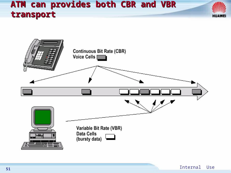
ATM for Telecommunications is Asynchronous Transfer Mode, (not Automatic Teller Machine!).
In general, ATM means that traffic is carried in small, fixed-length packets called cells.
A technology that integrates advantages of circuit switch and packet switch.
ATM can support any type of user services, such as voice, data, or video service.
51 Internal Use
ATM can provides both CBR and VBR transportATM can provides both CBR and VBR transportATM can provides both CBR and VBR transportATM can provides both CBR and VBR transport

52 Internal Use
ATM OverviewATM Overview
53byte fixed length cell= 5Bytes cell header+48Bytes payload.
ATM must set up virtual connection before communication.
ATM network will confer with terminal on parameter of QoS before the connection is set up.
Contract
5-Bytes Header
48-Bytes Payload

53 Internal Use
ATM Network ModelATM Network Model
UNI
UNI
NNI
NNINNI NNI
NNI
UNI
ATM Switch ATM End terminal
UNI = User to Network InterfaceNNI = Network to Network Interface

54 Internal Use
ATM CellATM Cell

55 Internal Use
ATM CellATM Cell
GFC ( Generic Flow Control): It is intended for control of a possible bus system at the user interface and is not used at the moment.
VPI ( Virtual Path Identifier): The VPI contains the second part of the addressing instructions and is of higher priority than the VCI.
VCI ( Virtual Channel Identifier): VCI in each case indicates a path section between switching centers or between the switching center and the subscriber.
PTI ( Payload Type Identifier): Indicates the type of data in the information field.
CLP ( Cell Loss Priority): Determines whether a cell can be preferentially deleted or not in the case of a transmission bottleneck.
HEC ( Header Error Control): Provided in order to control and, to some extent, correct errors in the header data that may occur. The HEC is used to synchronize the receiver to the start of the cell.

56 Internal Use
VP and VCVP and VCVP and VCVP and VC
think VPI as a bundle of virtual channels. (256 VPI on one link)
the individual virtual channels have unique VCIs. The VCI values may be reused in each virtual path.

57 Internal Use
ATM ConnectionsATM ConnectionsATM ConnectionsATM Connections

58 Internal Use
ATM Virtual ConnectionATM Virtual Connection
UNI cell VPI =1 VCI =1
UNI cell VPI =20 VCI =30
NNI cell VPI =26 VCI =44
NNI cell VPI =6 VCI =44
NNI cell VPI =2 VCI =44
1
2
3
1
2
3
1
3 2
2
31
ATM Virtual Connection Port VPI VCI
1 26 44
2 2 44
Port VPI VCI
1 2 44
2 6 44
Port VPI VCI
2 6 44
3 20 30
Port VPI VCI
1 1 1
2 26 44A B
In order to exchange cells between A and B, several tables must be set up in network node where the cells passed. After these tables have been set up, all the cells will be transferred along this route. This route is called Virtual Connection.
59 Internal Use
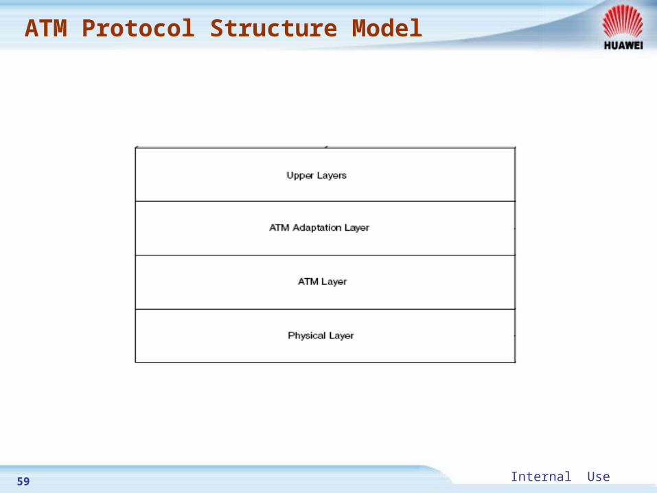
ATM Protocol Structure Model

60 Internal Use
ATM traffic classes ATM traffic classes

61 Internal Use
ATM traffic parameters ATM traffic parameters

62 Internal Use
ATM applications in UMTS networkATM applications in UMTS network
UTRAN
Iub
NodeB
RNC SGSN
RNC
NodeB
NodeB
NodeB
MSC
UE
UE
Uu Iu
Iur
Iu-CS
Iu-PS

63 Internal Use
ATM applications in UMTS networkATM applications in UMTS network

64 Internal Use