unclassified ad number new limitation … 9-8-3a8 range finder, t52 s~apport weapon it is fitted...
TRANSCRIPT

UNCLASSIFIED
AD NUMBER
AD491331
NEW LIMITATION CHANGE
TOApproved for public release, distributionunlimited
FROMDistribution authorized to U.S. Gov't.agencies and their contractors;Administrative/Operational Use; JAN 1957.Other requests shall be referred to ArmyMateriel Command, Washington, DC 20315.
AUTHORITY
FA, D/A ltr, 9 Apr 1976
THIS PAGE IS UNCLASSIFIED

THIS REPORT HAS BEEN DELIMITED
AND CLEARED FOR PUBLIC RELEASE
UNDER DOD DIRECTIVE 5200,20 AND
NO RESTRICTIONS ARE IMPOSED UPON
ITS USE AND DISCLOSURE,
DISTRIBUTION STATEMENT A
APPROVED FOR PUBLIC RELEASE;
DISTRIBUTION UNLIMITED,
UNCLASSIFIED
AD
DEFENSE DOCUMENTATION CENTERFOR
SCIENTIFIC AND TECHNICAL INFORMATION
CAMERON STATION ALEXANDRIA. VIRGINIA
UNCLASSI FIED

NOTICE: When government or other drawings, speci-fications or other data are used for any purposeother than in connection with a definitely relatedgovernment procurement operati on, the U. S.Government thereby incurs no responsibility, nor anyobligation whatsoever; and the fact that the Govern-ment may have forzaalated, furnished, or in any waysupplied the said drawings, specifications, or otherdata is not to be regarded by implication or other-wise as in any manner licensing the holder or anyother person or corporation, or conveying any rightsor permission to manufacture, use or sell anypatented invention that my in any way be relatedthereto.

"CHNICAL INFORMATION OFFICE, CHIEF OF ORDNANCEREPORT 9-8-3A8 January 1957
"DEVELOPMENT OPMAPM FOR TU U. s. AMY
MATZRI.L COMM BY TJ2 AMOF MATMI3L FUSARCH STAY1,
RANGE FINDER, T52 1AIIVZRICTY 0 OflS6t3GU
3785(I)oo
! n April 1954 a project was authorized for modification of the
p oduction model T43EI tank as the T43E2. The T43E2 was to have adtzrret different from that of its predecessor and would contain a
-•-ompletely redesigned fire control system based on a concept of di-j4+ iding between the gunner and the tank commander responsibility for.ý_ .4aying the gun. Previously, the gunner acquired the target, found
the range, and sighted his weapon. 'With the new system, target ac-( •N uisition and range finding would be done by the tank commander, and
-4 he gunner would give his full attention to laying the gun. It was"• -•-.believed that such a separation of duties would increase the effi-
ciency of the crew members concerned, reduce the time needed to ac-SC/)quire a target, and result in greater accuracy of fire.
The primary fire control system of the T43E2 tank is electro-mechanical in operation and allows either the commander or the gunnerto use either direct or indirect fire against targets at ranges be-tween 500 and 5,000 yards. It is composed of a T52 range finder, aT33 ballistics computer, a range servo amplifier that is a componentof the computer, a Tl servomechanism, a T14 superelevation trans-mitter, a T36 periscope drive-mount, a T44E1 periscope, a T159 infin-ity sight, a T16 cant corrector, and an inverter. The periscopedrive-mount, periscope, infinity sight, and cant corrector listedabove constitute one of two alternative installations for the gun-ner's station; the other would consist of a T38 periscope drive-mount, an M16E1 periscope, and an M30 instrument light. OCO andCONARC will decide which of these installations should be adopted.
A T172 direct-fire telescope in a T209 mount is mounted coax-ially with the 120-mm gun to give the gunner a secondary fire controlsystem to use if the primary system becomes inoperative. Two ballis-tic reticles, one for AP and the other for HE ammunition, are inter-changeable in the telescope.
For those occasions when the tank must be used as an artillery-DDC
RELATED TIR'S ju _SEP 3 0 1964TIR 9-8 Development of Fire Controlquipme t
for Armored VehiclesTIR 9-8-3 Development of Range Findeome
Vehicles D-IRA ADDC AVAtLABDUITY N3071,e
SNOT RELLASABL2 TO O01iCX 01 - 1 - Qualified requesters may obtain.949=MAT. £uV1m. oopes of thls report from DWO

TIR 9-8-3A8 RANGE FINDER, T52
s~apport weapon it is fitted with an M13 elevation quadrant, a T28azimuth indicator, and an M30 instrument light as equipment for the
ont.rol of indirect fire.
"JBefore discuss~ag the T52 range finder it will help to explainbri4ly-how the system of which it is a part functions. First, the
4 ....r fiPderlis operated to measure the range, which is then sent toe'V'Tea1Is•'1S' computer through the medium of a synchro transmitting
system. The computr-figures the amount of superelevation for theammunition to be used at the range fed into it and transmits the cal-culated data through four mechanical linkages and one electrical out-put to the periscope, the superelevation-signal generator, the super-elevation transmitter, the cant corrector, and the range-finder cantcorrector.
Introduction of superelevation data depresses the line of sightof both the range finder and the periscope. These depressions mustbe compensated for by elevating the gun to an amount equal to thedisplacement of the sighting instruments to again place the gun-laying reticles on the target. When there is no change in superele-vation, the drive-mount acts as a rigid linkage, and angular movementof the sighting instruments corresponds to the movement of the gun.fhis movement adds the computed superelevation angle to the originalgun-elevation angle for a given range and particular kind of ammuni-tion and accurately positions the gun with respect to the target.
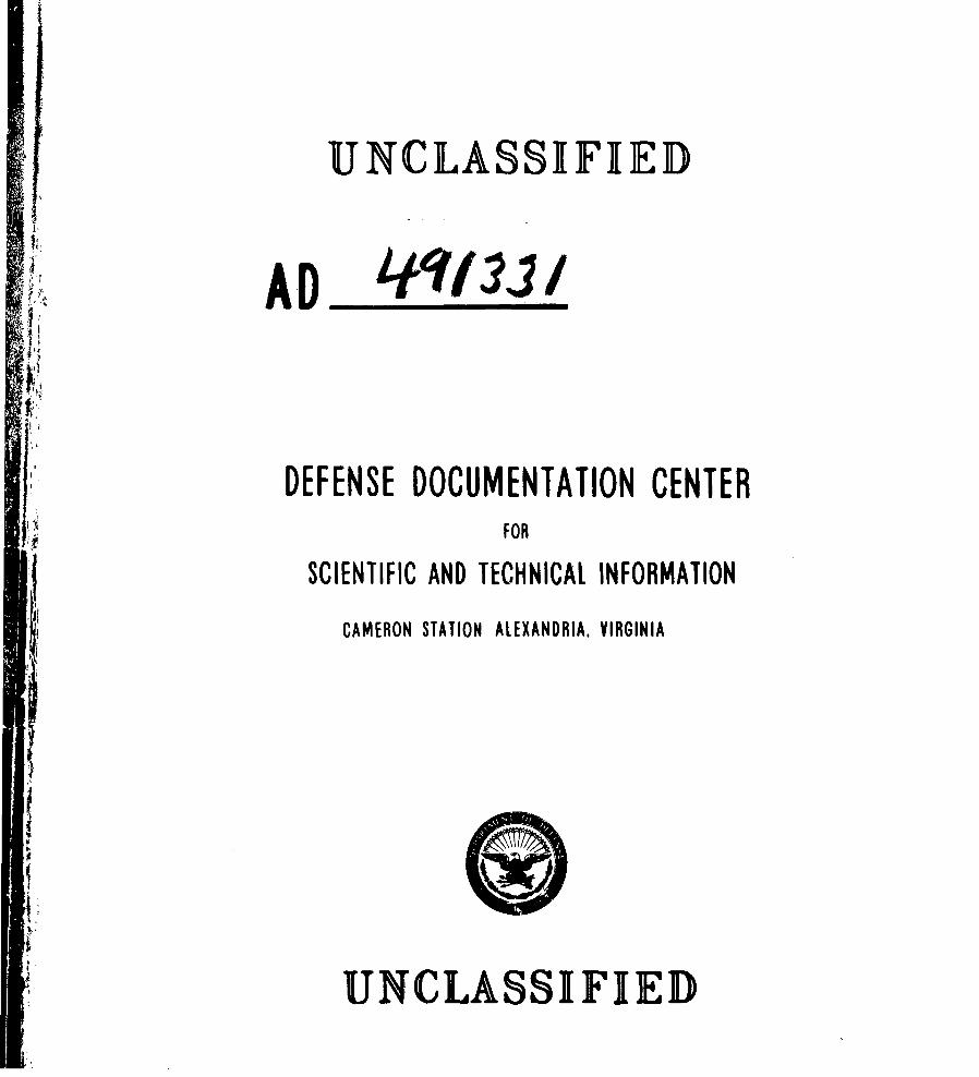
The T52 range finder is an auto-collimated, hermetically sealedinstrument with a 73-inch base. Although its principal use is forthe tank commander to determine the range, it has a secondary func-tion as an offset telescope by which he can lay the gun. In theevent of an emergency, the range finder can also be used as a direct-fire telescope. If the left telescope of the instrument should bedamaged, its gun-laying reticle can be transferred to the eyepiece ofthe right telescope by the operation of a transfer lever. A rangescale, normally seen through the left eyepiece, also can be trans-ferred to the right eyepiece by means of the transfer lever; it moveswhen the range knob is turned and shows the distance in yards whenthe instrument is ranged.
Training in the operation and adjustment of the range finder isessential to its effective use. Among the techniques with which theoperator must be familiar is that of calibrating the instrument toadapt it to his own anatomy and vision; this can be done by means ofthe internal correction-setting knob, the interpupillary-distanceknob, and the diopter-adjustment rings, all expressly provided fortLis purpose.
Successful use of the T52 range finder depends upon the abilityof its operator to employ stereoscopic vision in judging the distancebetween two objects in space. This ability can be developed bytraining, in the advantages of binocular fusion, in which the eyesconverge on an object at which their visual axes will intersect. Theimage of the object then falls on the fixation point of each retinaand it is seen as a single object occupying a certain area in space.When the-obJect-of regard is fixated, the angle between the objectand- the visual axes is termed the convergent angle. The size of the
RANGE FINDER, T52 TIR 9-8-3A8
RIGHT BEARING SUPPORT ELEVATION ASSEMBLY
' 4 , g i , . . .
ZUER 4ILA ATIO~NPW, COMMJN
FRONT VIEW OF RANGE FINDER, T52
convergent angle depends on the separation of the eyes and their dis-tance from the object. If the eyes become fixed on any other objectin space, another convergent angle results. The difference betweenthe two angles is the parallactic difference, normally interpreted bythe brain as a difference in distance between the objects.
A person's stereoscopic acuity depends on his ability to discrim-inate between small parallactic differences (differences in binocularparallax within the limits revealing relative range) and varies foreach individual. The ability to detect relative range differencescan be improved by increasing the effective distance between the eyes(base length) by means of a system of reflectors, and by identicaltelescopes for each eye. Greater base length and higher magnifica-tion make it possible to detect smaller binocular parallax differ-
I3EAWIO SUPPORT 2ND BoUBIN
SU$POK1 AR RMYLhT
RIGHT REAR VIEW OF RANGE FINDER, T52
- 3-

TIR 9-8-3A8 RANGE FINDER, T52
COUPLING FOR ELEvA'rTON SERVOMECHANISM TI.,,, : SPARE LAMP HOU~SING
MANUAL ELEVATION KNOBWZ- M DIOPTER ADJUSTMENT RINGS
SCANT CORIRECTION KNOEI•'
LEVEL VIAL LAMP HOUSING \
CANT LEVEL VIAL INTERPUPILLARY DISTANCE KNOB
LEFT SIDE OF RANGE FINDER, T52
ences. An optical instrument containing these features can increasethe sensitivity of the eyes to binocular parallax differences andallow the observer to determine when there is no apparent differencein range between two objects, although he cannot measure the relativedifference in yards.
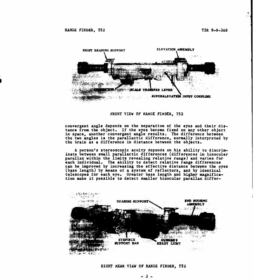
A stereo-reticle pattern in the internal-collimator system of theT5z range finder gives the effect of a third dimension in which twopairs of vertical bars and a single bar, equally spaced laterallyseem to be at different distances from the observer. The lowest bar,in the center of the pattern, appears to be farthest from the ob-server and is used as the reference point for ranging. The otherbars aid in locating the lower bar in space.
Measuring the range requires that the target, regardless of itsapparent or true distance, be made to seem at the same distance fromthe observer as the reference bar of the stereo reticle. By turningthe range knob the range-compensator assembly changes the convergentangle for the target while the convergent angle of the reticle pat-tern is unchanged. The parallactic difference resulting from thedifference between the convergent angles increases or decreases; whenthe parallactic difference becomes zero, the convergent angles areequal, and the reference bar of the reticle and the target appear tobe at the same distance from the observer. When this seeming equalityof distance is obtained, the range is determined and transmitted tothe r33 ballistics computer by an electrical signal which correspondsto a logarithm of the range.
"- 4

RANGE FINDER, T52 TIR 9-8-3A8
HALVING KNOB
INDCATR LGHTINTERNAL CORRECTION
EYEPIFCES INDICATOR LIGHT SETTING KNOB
RANGE SR SIC
KNOB SELECTOR.... SWITCH
ELEVATION
BORESIGHT KNOB / RHEOSTAT KNOB
ELEVATION BORESIGHTDLOCKING LEVER DEFLECTION (AZIMUTH)BORESIGHT LOCKING LEVER
DEFLECTION (AZIMUTH)BORESIGHT KNOB
RIGHT SIDE OF RANGE FINDER, T52
When the range signal is received by the computer it is convertedinto superelevation data that are sent to the periscope drive-mountand the superelevation transmitter. The range finder and the peri-scope are then moved in superelevation. Movement of the range findercauses the stereo reticle to move up or down (an aetion known asstereo dip); this condition is overcome when the superelevation-sig-nal generator causes the gun-elevation part of the hydraulic gun-control system to operate. In consequence, gun elevation occurs whenthe range finder's range knob is moved; during this movement thestereo-reticle pattern stays on the target.
A signal created at the superelevation transmitter by elevationof the gun causes the elevation synchromechanism to elevate or de-press the range finder correspondingly. If. however, the elevationservomechanism becomes inoperable, it can be disconnected from therange finder, and the instrument can then be elevated or depressed bymeans of a manual elevation knob.
The T52 range finder is mounted in a right bearing support and an
- 5 -

TIR 9-8-3A8 RANGE FINDER, T52
SFLEXIBLE CABLE: (FROM BALLISTiCS COMPUTERT3
-"JPERELEVATION INPUT COUPLING
SCALE TRANSFER LEVER•
PARTIAL VIEW OF RANGE FINDER, T52, INSTALLED
elevation assembly attached to the roof plate of' the turret. Therange finder moves with the turret in azimuth, and ball bearings inthe mounting units allow it to be rotated about an axis parallel tothe gun trunnions so that it can follow the gun in elevation as di-rected by the servo system.
The optical systems and mechanisms of the T52 range finder arecontained in a main housing assembly an eyepiece housing, and twoidentical end housing assemblies. All the optical components of theinstrument except those in the end housing assemblies and the eye-pieces are in the main housing assembly. In this assembly there arealso the cant corrector and the elevation and range-drive mechanisms.The right and left telescope systems are symmetrical except for therange-compensator assembly, which is in the right system only. Awindow in the main assembly excludes dust and moisture from the range
-- 6--
RANGE FINDER, T52 TIR 9-8-3A8
IJ
LOWER
MEASURING ... •i•• ..BAR ..
STEREOSCOPIC IMPRESSION OF THE RETICLEOF RANGE FINDER, T52
finder while permitting light to enter. A neutral filter controlledby a rod geared to the filter mounts can be used to decrease thebrightness of the field image without adversely affecting the imagecolor, This filter can be introduced into the optical system or re-moved from it at the desire of the operator.
The two end housing assemblies are identical and are interchange-able on the same instrument and other T52 range finders. When suchsubstitutions are made, it is unnecessary to recalibrate or boresightthe instruments. Each assembly consists of an aluminum housing withan end window and cover, a penta reflector, an optical wedge, a purg-ing valve through which the assembly can be flushed with dry nitrogen,
7
TIR 9-8-3A8 RANGE FINDER, T52
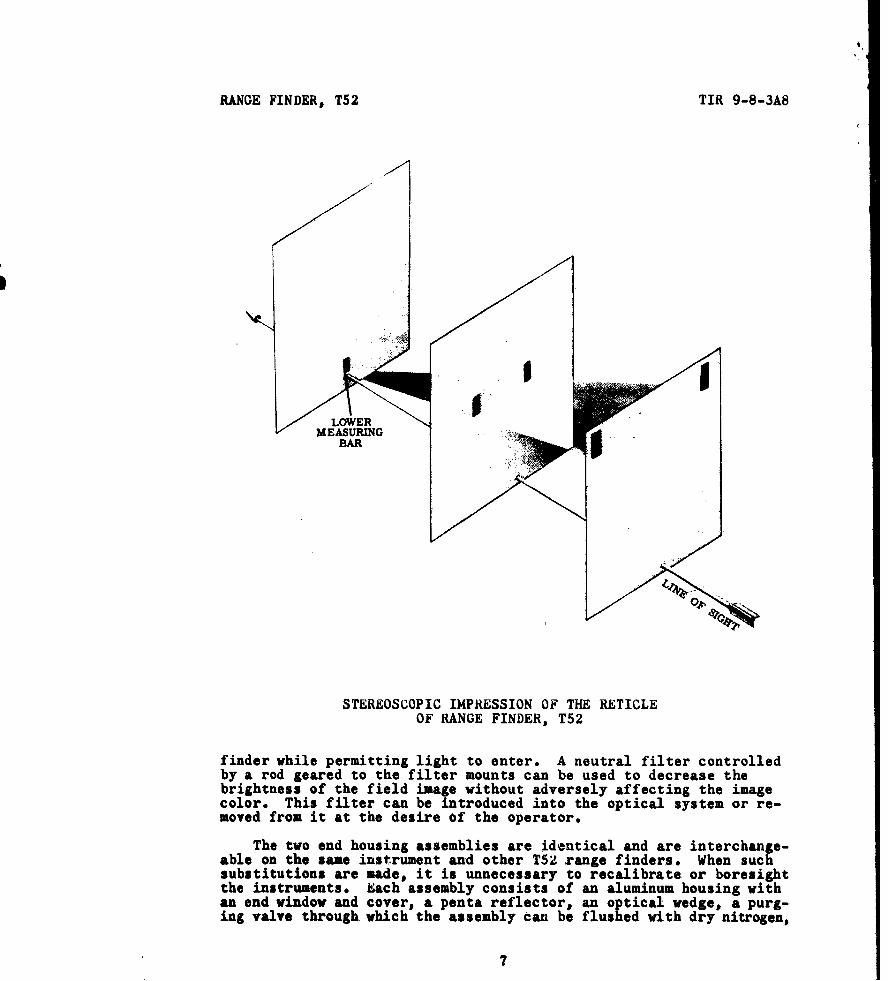
2 MitS
2 MiRS
V2' MILS
' I MIL 4 MRUS MiLS
I LEAD 2 LEADS
LEAD LIMES IID, LEAD LEADS
eqotl 1NAEQS
RANGE LINES
GUN-LAYING RETICLE
and a mounting surface with a wedge and key assembly for orientingthe housing when it is installed. When the target image enters thewindow it is reflected by the penta reflector to the wedge. Becausethe two mirror surfaces of the penta reflector are attached perpendi-cularly to a common glass base there is no effect on the over-all de-viation and no error is introduced. Rotating the penta reflector byturning an externally accessible spring-loaded screw in the housingadjusts it for elevation. Image tilt can be corrected by rotatingthe penta reflector about an axis parallel to the reflected ray.
-8

RANGE FINDER, T52 TIR 9-8-3A8
InL RANGE SCALE
t', STEREO RETICLE
GUN- -- + - - LAYING
I RETICLE
RETICLE PATTERNS OF RANGE FINDER, T52
Correction for image tilt in the housing assembly is made by loosen-ing the cover screws and rotating the cover the desired amount.
The wedge is a weak prism with a deviation angle of about 5 min-utes; it is the last optic through which light must pass before leav-ing the end housing assembly. The slight error in deviation that maybe present in the penta reflector can be compensated for by rota tingthe wedge. Vertical errors introduced into the wedge can be neutral-ized by means of the elevation adjustment at the penta reflector.
-9--

TIR 9-8-3A8 RANGE FINDER, T52
HOUSING COVE1R
WEDGE AND KEY ASSEMBLYS~/
END WINDOW
PURGING VALVE
WEDG MOUNTING SURFACE
END HOUSING ASSEMBLIES OF RANGE FINDER, T52
Light entering the end housing assemblies is directed toward thecenter of the range finder, where it enters the telescope systems,passes through various series of lenses and prisms, and then goesthrough the eyepieces to the eyes of the observer. Light projectedfrom the internal collimator system into the telescope systems en-ables the image of the gun-laying reticles and scales to be combinedwith each target image to produce composite images in the eyepieces.
Wherever practicable, the optical elements of the range finderare given a low-reflectance coating that reduces reflections and in-creases the transmission of light. Internal reflections are reducedby coating or painting almost all mechanisms in the instrument with adull black finish.
In addition to the optical elements of' the end housing assemblies,the T52 has an identical telescope system on each side of its center,a range-compensator assembly, an internal collimator assembly, and aneyepiece assembly.
Tho range-compensator assembly contains two single-element lenses
- 10 -

RANGE FINDER, T52 TIR 9-8-3A8
C ANI (U ff(l '•IOh
RANGE COMPENSATOR ASSEMBLY
SCALE TRANSFER PRIS.M
SYNCHRO CONTROL TRANSMITTER 15CTX4a TSUPLHELLVAIHON INPt L CQL ILIN.
MAIN HOUSING ASSEMBLY OF RANGE FINDER, T52
of equal but opposite power and long focal length. The circular nega-tive lens is in a fixed position on the optical axis of the telescope,in front of the rectangular positive lens. Turning the range knob ro-tates a compensator lead screw that moves the positive lens horizon-tally until it is about perpendicular to the direction of the lightfrom the target. The deviation resulting from this movement allowsthe operator to equalize the convergent angles for the target and thestereo-reticle pattern so that the parallactic difference is broughtto zero.
Light from the internal collimator system is deflected toward thetelescope's objective lens by a partial penta reflector mechanicallysimilar to the penta reflector in the end housing assembly. Thislight, and that from the target, are converged by the objective lenstoward its focal plane. The images can be adjusted for focus by mov-ing the objective lens along its optical axis. The limiting apertureof the cell holding the objective lens is 1.5 inches in diameter; itforms the entrance pupil for the telescope system, and determines theamount of illuination of the images in the telescope assembly.
- 11 -

TIR 9-8-3A8 RANGE FINDER, T52
NEGATIVfELENS
SPOSITIVESLENS
SLOGARITHM
GEARS
FACE-SERRATEDCOUPLING
INPUT GEAR (TO SYNCHROCONTROL TRANSMITTER)
RANGE-COMPENSATOR ASSEMBLY OF RANGE FINDER, T52
Light from the objective Lens continues toward the pechan-prismassembly, which consists of two prisms on a common support of ballbearings. These prisms are so mounted that their positions can beadjusted in relation to each other and to the support. The prismassembly makes it possible to keep the range finder's eyepieces sta-tionary while the instrument is rotated about its axis in elevationor depression. Motion of the range finder is transmitted to thepechan prisms by a differential. Gearing rotates the pechan prismsin the same direction as the range finder but in an amount equal toonly one half of the range finder's rotation. This rotation of theprisms keeps the images of the target, gun-laying reticles, and rangescales from tilting to one side or the other when the range finder iselevated or depressed. The images are reverted when they leave the
- 12 -
RANGE FINDER, T52 TIR 9-8-3A8
MANUAL ELEVATION BEVEL GEARS LEFT MAIN BEARING
KNOB
L • HYPOID PINION'
HYPOID GEAR
ANTI-BACKLASH DEVICE
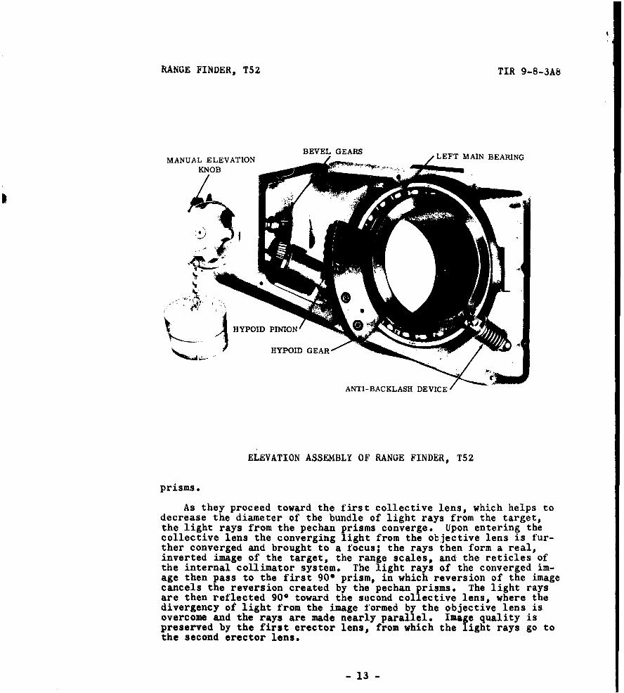
ELEVATION ASSEMBLY OF RANGE FINDER, T52
prisms.
As they proceed toward the first collective lens, which helps todecrease the diameter of the bundle of light rays from the target,the light rays from the pechan prisms converge. Upon entering thecollective lens the converging light from the objective lens is fur-ther converged and brought to a focus; the rays then form a real,inverted image of the target, the range scales, and the reticles ofthe internal collimator system. The light rays of the converged im-age then pass to the first 900 prism, in which reversion of the imagecancels the reversion created by the pechan prisms. The light raysare then reflected 900 toward the second collective lens, where thedivergency of light from the image formed by the objective lens isovercome and the rays are made nearly parallel. Image quality ispreserved by the first erector lens, from which the light rays go tothe second erector lens.
- 13 -

TIR 9-8-3A8 RANGE FINDER, T52
STOP SCREW
CANT INPUT \K)"CANT CORRECTOROUTPUT COUPLING
SUPERELEVATION INPUT SHAFT
CANT CORRECTOR OF RANGE FINDER, T52
The second erector lens converges the light rays it receives toform a real, erect image of the target, the range scale, and the reti-cles at the focal plane of the eyepieces. Inversion of the image hasnow occurred twice, and the image at the focal plane of the eyepieceassembly is erect. Converging light from the second erector lensreaches the second 900 prism, from which the rays are deviated down-ward approximately 90' toward the 1100 prism and are inverted at thesame time.
The 1100 prism has three optically flat surfaces, through thefirst of which light from the 90 prism enters perpendicularly. Thelight is then inverted by reflection at the second surface and leavesthe prism perpendicularly at the third surface. From this last sur-
- 14 -

RANGE FINDER, T52 TIR 9-8-3A8
FACE SERRATED COUPLING
SYNCHRO CONTROL TRANSMITTER GEAR•
S~SYNCHRO CONTROL TRANSMITTER
SLAMP SWITCH CAPACITOR ANTI-BACKLASH SPRING'w
RING STOPS
INPUT SHAFT
RANGE DRIVE ASSEMBLY OF RANGE FINDER, T52
face the light travels upward 200 from the horizontal, which corre-sponds to the upward tilt of the axes of the eyepieces. This angleof the eyepieces enables the operator to use them from a more comfort-able position than would otherwise be possible.
When the light leaves the 110" prism it proceeds to the rhomboidprism, which is bonded to a mount attached to the cell of the eye-piece. The rhomboid prism has four optically flat surfaces, one ofwhich is perpendicular to the light received from the 1100 prism.The light enters the first of these surfaces, is reflected from thesecond surface, is again reflected from the third surface, and leavesthe prism through the fourth surface without any inversion having oc-curred. The rhomboid prism permits adjustments of the interpupillarydistance (IPD) to be made without affecting collimation or rangingaccuracy. In this operation a mechanism moves the eyepiece assemblylaterally and rotates the rhomboid prism about the mechanical axis.When the mechanism is properly adjusted the observer is unable to de-tect any rotation as he looks through the eyepieces. Light from therhomboid prism converges toward a focus near the diaphragm of the eye-piece.
Each eyepiece contains an eye lens, a field lens, and a diaphragm
- 15 -
TIR 9-8-3A8 RANGE FINDER, T52
mounted within a cell. The cell can be moved along the optical axisand focused for the in~dividual needs of the operator by turning adiopter-adjustment ring on which there is a scale graduated from -3to +3 diopters. The distance between the eyepieces can be changed tomeet the requirement of the operator by means of the IPU knob on theoutside of the range finder. A scale on this knob is graduated from58 to 72 in one-millimeter increments. The diaphragm, a circularlimiting aperture near the final image formed by the telescope system,functions as a field stop and gives a well-defined circular border tothe field of view; at the same time, it eliminates unwanted straylight that might disturb the observer. The field lens receives thelight coming from the image near the diaphragm and directs it towardthe eye lens. The last optic in the eyepiece assembly is the eyelens, which is responsible for the 8.6-power magnification of therange finder. Finally, the eyepiece assembly has an exit pupil witha diameter of 0.174 inch and so placed that the observer's eye is0.883 inch from the eye lens when the eye is in the proper positionfor viewing. When his eye is properly placed, the observer can lookat any object in the field of view simply by turning his eye in thecorrect direction.
The stereo reticles, gun-laying reticle, range scale, and theoptical elements necessary for projecting their images into the tele-scope system through the partial penta reflector, are in the internalcollimator system. Because the right and left collimator systems aresymmetrical, only one of them will be described.
The gun-laying reticle is a thin piece of optical glass, approxi-mately rectangular in shape, on which the reticle pattern is formedby transparent areas in an opaque background. Light from a l.mp be-neath the reticle passes through a small window, proceeds through thetransparent areas of the reticle and is then directed upward to thefirst 900 prism, which is directly above the reticle. The intensityof the illumination may be controlled for night firing by adjustmentof the rheostat knob on the outside of the range finder's main hous-ing.
The light from the reticle is next reflected from the first 900prism to the second 900 prism, which reflects it upward to the verti-cal reflecting mirror. This mirror is fastened to a support that canbe rotated about a horizontal axis parallel to the mirror's surfaceto move the image of the gun-laying reticle upward or downward formaking changes in boresight elevation. Light reflected from the mir-ror goes upward to the scale-transfer prism.
Light from the same lamp illuminates both the gun-laying reticleand the range scale. The range scale, which is adjacent to the gun-laying reticle, has its scale and range numbers formed by transparentareas in an opaque background. After it passes through the transpar-ent areas of the scale the light follows the same path as it doesafter it goes through the gun-laying reticle.
The scale-transfer prism, located at the mid-point of the inter-nal collimator system, consists of two 90* prisms cemented togetherat their hypotenuse faces. A thin film of partially reflecting mater-ial cemented between the prisms allows only half the light from the
- 16 -

RANGE FINDER, T52 TIR 9-8-3A8
range scale and the gun-laying reticle to be reflected while lightfrom the stereo reticles (also with a 50 per cent loss of illumina-tion) is simultaneously transmitted through the prism. Normally, theprism reflects the light from the range scale and the gun-laying ret-icle into the left side of the collimator system, but if the leftsystem is damaged the light can be transferred to the right system bymeans of the scale-transfer lever on the outside of the instrument.In addition, the transfer prism allows the right side of the systemto be used as a direct-fire telescope by projecting the gun-layingreticle into the right telescope system.
The right and left internal collimator systems each has its ownstereo reticle, which consists of two glass disks cemented together.Slightly above the center of one disk there is a small prism directlyin line with a reticle mask on the other disk. The reticle patternis created when light from a lamp under the prism is reflected fromit and passes through the transparent areas of the mask. The patternis composed of five short, vertical, luminous bars arranged in awide 'IV." As seen through the left eyepiece the horizontal spacingbetween the bars is slightly greater in the left half of the patternthan in the right half; the reverse is true when the pattern is view-ed through the right eyepiece. Thus, the various bars have differentconvergent angles, which makes them seem to be at different distancesfrom the observer and appear as a three-dimensional projection ofonly one pattern. Although the light rays from each reticle passthrough each opposite reticle there is no significant effect on theimage.
Vertical adjustment of the right stereo reticle with respect tothe left reticle is made by operation of a halving knob on the out-side of the range finder. Turning the halving knob moves the rightreticle up or down until in the field of view it appears to be at thesame height as the left reticle. This makes it easier for the opera-tor to fuse the images of the two reticles and use the range finderwith greater comfort and accuracy.
The two collimator lenses in each side of the system are designedto produce a clear image without unwanted aberrations. tach is asingle positive lens composed of two lenses cemented together. Di-verging light from the reticles and range scale is received by thefirst collimator lens, which decreases the divergency. The remainingdivergency then is decreased by the second collimator lens until therays of light that leave it are practically parallel.
The correction wedges in the internal collimator system are simi-lar to the wedge in the end housing assembly. Two optically identi-cal wedges in each side of the collimator system have the same devi-ating power and make possible a limitless number of combinations ofthe wedges to obtain the desired amount and direction of deviationproduced by a pair of wedges. The final amount and direction of de-viation will depend upon the combination of positions in which thewedges are used.
Alignment of the left collimator system with the left side of thetelescope system is made by the two left collimator wedges. Rotationof either of these wedges, or of both wedges in combination, moves
- 17 -

TIR 9-8-3A8 RANGE FINDER, T52
the images of the reticles and range scales in any direction to cor-rect small optical misalignments. After alignment is obtained, thewedges are locked in position.
The right and left correction wedges differ only in the mountingand functioning of the right outer wedge, which is mechanicallygeared to the internal correction system (IGS) knob. When the ICSknob is rotated the image of the stereo reticles seen through theright eyepiece moves to one side or the other, but appears to theobserver to move toward him or away from him. This phenomenon en-ables the observer to adjust the range finder to satisfy his ownjudgment of stereo contact. Before he uses the instrument in thefield, the operator must find what setting of the ICS knob is neces-sary for him to obtain accuracy in ranging. To determine this opti-mum setting, the operator must observe a target at a known distanceand set the range scale to agree with the known range. He nextmakes the proper IPD setting, diopter setting, and halving adjustment,after which he observes the apparent relative distance between thelower measuring bar of the stereo pattern and the target. He thenturns the ICS knob to make the reticle appear to move toward or fromhim until, in his judgment, the lower measuring bar and the targetare at the same distance. When this is done he notes the reading onthe ICS knob scale, which is his personal setting whenever he wishesto range. Although in an emergency this setting could be used withpthler range finders, it is preferable to establish a new ICS settingfor each instrument.
The penta reflector of the internal collimator system is mechani-cally and optically like the penta reflector in the end housingassembly. Parallel light comes to it from the wedges and is deviatedtoward the partial penta reflector, which transmits light from thetarget and reflects the light from the internal collimator system.These two light beams are joined by the partial penta reflector be-fore entering the objective system. This junction of the two beamsis accomplished by the first surface mirror, which is coated with apartially reflecting material that both reflects and transmits lightand is positioned in the axis of the main telescope housing. Whenthe fused light from the internal collimator system enters the objec-tive system it follows the same path as the light from the targetimage.
All the controls for operation of the T52 are on the outside ofthe instrument. In addition, there is a headrest that permits easeof eye placement at the exit pupil and that can be adjusted to fitthe facial contour of the user. Two thumb screws at its sides allowthe position of the headrest to be altered to give the operator thebest head position for viewing.
Before, he starts ranging the operator should make the proper ad-justments of the controls and ascertain that the instrument is com-pletely ready for use.
Controls other than the IPD knob, diopter-adjustment rings, halv-ing knob, range knob, ICS knob, rheostat knob, filter lever, andscale-transfer lever - all of which have been discussed - are therange servo switch, cant-correction knob, scale selector, boresight
- 18 -

RANGE FINODR, T52 TIR 9-8-3A8
knobs, and manual elevation knob.
The range servo switch allows the range finder to be operated in-dependently without stereo dip normally occurring when other parts ofthe fire control system are operating, When the switch is in the"OFF" position, the signal from the synchro control transmitter can-not be sent to the computer. An indicator light next to the switchis illuminated when the switch is in the "ON" position.
Correction for cant of the vehicle is introduced into the rangefinder by turning the cant-correction knob. The knob is rotated un-til the bubble in the cant level vial is centered, whereupon a multi-plying mechanism in the instrument causes the gun-laying reticle tomove in azimuth, by means of an involute cam, to correct the deflec-tion cant error. Superelevation which also must be applied to com-pensate for cant, is automatically fed into the range finder by thecomputer through a flexible cable. The azimuth and superelevation-correction signals are combined in the multiplying mechanism to yieldthe correct deflection shift of the gun-laying reticle.
The scale selector, which has four positi, s, permits the opera-tor to view only the reticles and scales nece. ary at the time. Whenit is turned to the first position, the selector illuminates thestereo reticles only. In the second position, it illuminates thegun-laying reticle and the range scale together. Turned to the thirdposition, it simultaneously illuminates the stereo reticles, a gun-laying reticle, and the range scale. In the fourth position, itturns off all the lights.
A deflection- and an elevation-boresight knob are on the rear ofthe range finder. Each knob has a lock, an adjustable scale gradua-ted from 0.5 to 5.5 mils in increments of 0.1 mil, a stop mechanism,and the driving portion of a coupling. Turning the hexagonal deflec-tion knob causes the gun-laying reticle to move horizontally in thefield of view. Turning the serrated elevation knob rotates a mirrorthat positions the image of the gun-laying reticle upward or downwardin the field of view.
The manual elevation knob is used to elevate or depress the rangefinder when the T1 elevation servomechanism is inoperative. A coverfor the knob bears a legend reading: "Manual knob for emergency useonly. uisconnect drive coupling before using." The drive couplingis the coupling between the elevation servomechanism and the eleva-tion gearing of the range finder. A thumb latch clamp on the servo-mechanism output shaft is the driving portion of the coupling; itmust be unlocked and pushed back on the shaft to permit free rotationof the range finder.
The elevation or depression angle directed by the Tl elevationservomechanism is transmitted to the range finder by a gear train inthe elevation assembly. A hypoid gear segment secured to the flange.of the adapter in which the range finder is mounted is driven by ahypoid pinion rotated by bevel gears. The elevation assembly iseguipped with a device that minimizes backlash and variable deflec-tions that would reduce elevation accuracy. Ring stops on the inputshaft of the assembly limit the elevation of the range finder to
-19-

TIR 9-8-JAS RANGE FINDERO T52
293 mils and its depression to 240 mils. These limits are greaterthan the maximum values called tor by the fire control system, whichare 267 mils elevation determined by gun elevation and 212 mils de-pression (142 mils for gun depression and 70 mils for superelevationdip). A spring-loaded pivoted brake shoe prevents mechanical feed-back through the hypoid gear of the assembly whzn the elevationservomechanism is disconnected for manual elevation or depression ofthe range finder* Access to the gearing and brake mechanism is ob-tained by removing two cover plates.
Correction of the gun-laying reticle for cant of the vehicle ismade through the medium of a linkage-type multiplier in the rangefinder's cant corrector. The multiplier combines cant and superele-vation values to rotate an involute cam that gives the necessary mo-tion to the reticle. The cant function is manually introduced intothe cant corrector by rotating the cant-correction knob until thebubble in the cant level vial is centered. A complete revolution ofthe cant-correction knob is equal to 5.6250 of cant. The full rangeof correction for cant is ±150. The correction is zero when thecant-correction knob is in the detent position, at which positionrange and ballistics functions introduced elsewhere in the system donot appreciably affect the horizontal position of the gun-layingreticle. No correction for projectile drift is fed into the rangefinder.
The cant corrector automatically receives superelevation datafrom the TSJ ballistics computer over a flexible cable coupled to thesuperelevation input of the range finder. Rotation of the superele-vation-input coupling 12 revolutions clockwise from the extremecounterclockwise position, together with alignment of its index marks,introduces 26.6 mils of superelevation into the cant corrector. Thisis the position used to make the cant corrector conform with the com-uter. The counterclockwise rotation of the superelevation input isimited by a stop screw. It is important that excessive torques not
be applied to the superelevation-input coupling because of the largegearing ratio in the mechanism of the cant corrector.
Rotation of the range knob to the range-compensator assembly istransmitted by a range-driven assembly with a gear drive having a 10to 1 ratio. The range input to the range finder is limited to dis-tances between 480 and 5,000 yards by ring stops on the input shaft.A face-serrated coupling on the range-drive assembly mates with a sim-ilar? coupling on the range-compensator assembly input gear. the in-put gear meshes with the synchro control transmitter gear and pro-duces a rotation that is equal to the natural logarithm of the rangeand generates an electrical signal of this range function that isreceived by the synchro control transformer in the ballistics com-puter. Backlash in the range drive assembly is removed by an anti-backlash spring that acts on the synchro control transmitter gear.
User tests of the T52 range finder as an integral part of thefire control system of the T43k;2 120-mm gun tank are now being madeby CONARC Board No 2.
- 20 -

RANGE FInOhR, T52 TIR 9-8-sA8
TENTATIVE PRINCIPAL CHARACTERISTIUS
Length 80 inWidth 29 inHeight 15.5 inWeight 275 lbField of view 4.30Magnification 8.6xBase length 73 inDiameter of exit pupil 0.174 in (4.42 mm)Clear-eye distance 0.881 inDiopter (one) 0.046 inUnit of error 3.4 ( ____
1,000Range 500 to 5,000 ydScale graduation
Range 500 to 5,000 ydDiopter -3 to +3Interpupillary 58 to 72 mmI CS 0 to 50 units of error(normal setting, 25)
Azimuth boresight knob 0.5 to 5.5 mils (normalsetting, 3)
Elevation boresight knob 0.5 to 5.5 mils (normalsetting, 3)
Lamp operating voltage 24 v, dcSynchro operating voltage 115 v, 400 cycle, acElevation limits (set by
internal stops) 160 elevation, 140 de-pression (allows for 6'superelevation)
•21 -