unclassified - dtic.mil security ... casa study w/g reports /////a ida report volume iv ... ecs...
TRANSCRIPT

UNCLASSIFIED SECURITY CLASSIFICATION OF THIS PAGE (Whm Data Bntarad)
REPORT DOCUMENTATION PAGE READ INSTRUCTIONS BEFORE COMPLETING FORM
1. REPORT NUMBER 2. GOVT ACCESSION NO. 3. RECIPIENT'S CATALOG NUMBER
4. TITLE fand Sub«tl«;
F-16 APG-66 Fire Control Radar Case Study Report (IDA/OSD R&M Study)
5. TYPE OF REPORT 4 PERIOD COVERED
Final July 1982 - August 1983
S. PERFORMING ORG. REPORT NUMBER IDA Record Document D-21
7. AUTHORCi;
Paul F. Goree IDA R&M Case Study Director
8. CONTRACT OR GRANT NUMBERf«J
MDA 903 79 C 0018
9. PERFORMING ORGANIZATION NAME AND ADDRESS Institute for Defense Analyses 1801 N. Beauregard Street Alexandria, VA 22311
10. PROGRAM ELEMENT, PROJECT, TASK AREA a WORK UNIT NUMBERS
Task T-2-126
II. CONTROLLING OFFICE NAME AND ADDRESS
Office of the Assistant Secretary of Defense (MRA&L), The Pentagon Washington, D.C. 20301
12. REPORT DATE August 1983
13. NUMBER OF PAGES 273
U. MONITORING AGENCY NAME & AOORESSCf/ dlllartnt Irom Controlling OHIca)
DoD-IDA Management Office 1801 N. Beauregard Street Alexandria, VA 22311
IS. SECURITY CLASS, (ol thia raport)
UNCLASSIFIED
I5«. DECLASSIFICATION/DOWNGRADING SCHEDULE
N/A 16. DISTRIBUTION STATEMENT (ol thia Raport)
Approved for public release; distribution unlimited.
17. DISTRIBUTION STATEMENT foi Iha abalract antarad In Block 20, It dlllarent Irom Raport)
None
IB. SUPPLEMENTARY NOTES
N/A
19. KEY WORDS (Continue on revars* aid9 If nmcmaamry and tdmnttty by block number)
reliability, maintainability, readiness, case study, program structxiring, lessons learned, F-16, APG-66, radar
20. ABSTRACT (Contlrma on ravaraa aida It nacaaaMry and Idanttty by block numbar)
This document records the activities and presents the findings of the F-16 APG-66 Fire Control Radar Case Study Working Group part of the IDA/OSD Reliability and Maintainability Study, conducted during the period frcm July 1982 through August 1983.
DO ,3 ̂*^", 1473 EDfTtON OF t NOV SS IS OBSOLETE UNCLASSIFIED SECURITY CLASSIFICATIOM PF THIS PAGE (Whan Data Entarad)

Copy 1 0 of 200 copies
4PA142075 ^n%;^^ division
'""^ 33943
IDA RECORD DOCUMENT 0-21
F-16 APG-66 FIRE CONTROL RADAR CASE STUDY REPORT
(IDA/OSD R&M STUDY)
Paul F. Goree IDA R&M Case Study Director DTIC
ELECTEpi JUN8 1984 '
August 1983
The views axprasssd within this docament are those of the working group only. Publication oi this document does not indicate endorse- ment fay IDA, its staff, or Its sponsoring agencies. ^^^
Prepared/or Office of the Under Secretary of Defense for Research and Engineering
and Office of the Assistant Secretary of Defense (Manpower, Reserve Affairs and Logistics)
INSTITUTE FOR DEFENSE ANALYSES H
8 4 06 06 007 IDA Log No. HQ m-ZmS5

The work reported in this document was conducted under contract MDA 903 79 0 0018 for the Department of Defense. The publication of this IDA Record Document does not indicate endorsement by the Department of Defense, nor should the contents be construed as reflecting the official position of that agency.
Approved for public release; distribution unlimited.

IDA RECORD DOCUMENT D-21
F-16 APG-66 FIRE CONTROL RADAR CASE STUDY REPORT
(IDA/OSD R&M STUDY)
Paul F. Goree IDA R&M Case Study Director
August 1983
IDA INSTITUTE FOR DEFENSE ANALYSES
1801 N. Beauregard Street, Alexandria, Virginia 22311 Contract MDA 903 79 C 0018
Task T-2-126

RELIABILITY AND MAINTAINABILITY STUDY
— REPORT STRUCTURE —
IDA REPORT R-272
VOLUME I
EXECUTIVE SUMMARY
IDA REPORT R-272
VOLUME II
CORE GROUP
REPORT
IDA REPORT R-272
VOLUME III
Casa Study Analysis
IDA RECORD DOCUMENTS
Casa Study w/G Reports
///////A
IDA REPORT
VOLUME IV
R-272 A (
iV
%
Bibliography
THIS DOCUMENT (IDA Record Document D-21)

PREFACE
As a result of the 1981 Defense Science Board Summer Study on Operational Readi-
ness, Task Order T-2-126 was generated to look at potential steps toward improving
the Material Readiness Posture of DoD (Short Title: R&M Study). This task order was
structured to address the improvement of R&M and readiness through innovative program
structuring and applications of new and advancing technology. Volume I summarizes
the total study activity. Volume II integrates analysis relative to Volume III,
program structuring aspects, and Volume IV, new and advancing technology aspects.
The objective of this study as defined by the task order is:
"Identify and provide support for high payoff actions which the DoD can take to improve the military system design, development and support pro- cess so as to provide quantum improvement in R&M and readiness through innovative uses of advancing technology and program structure."
The scope of this study as defined by the task order is:
To (1) identify high-payoff areas where the DoD could improve current system design, development program structure and system support policies, with the objective of enhancing peacetime availability of major weapons systems and the potential to make a rapid transition to high wartime activity rates, to sustain such rates and to do so with the most econom- ical use of scarce resources possible, (2) assess the impact of advancing technology on the recommended approaches and guidelines, and (3) evaluate the potential and recommend strategies that might result in quantum in- creases in R&M or readiness through innovative uses of advancing technology.
P-1

The approach taken for the study was focused on producing meaningful implement-
able recommendations substantiated by quantitative data with implementation plans
and vehicles to be provided where practical. To accomplish this, emphasis was placed
upon the elucidation and integration of the expert knowledge and experience of engi-
neers, developers, managers, testers and users involved with the complete acquisition
cycle of weapons systems programs as well as upon supporting analysis. A search was
conducted through major industrial companies, a director was selected and the follow-
ing general plan was adopted.
General Study Plan
Vol. Ill • Select, analyze and review existing successful program
Vol. IV • Analyze and review related new and advanced technology
Vol. II (• Analyze and integrate review results (• Develop, coordinate and refine new concepts
Vol. I • Present new concepts to DoD with implementation plan and recommen- dations for application.
The approach to implementing the plan was based on an executive council core
group for organization, analysis, integration and continuity; making extensive use
of working groups, heavy military and industry involvement and participation, and
coordination and refinement through joint industry/service analysis and review.
Overall study organization is shown in Fig. P-1.
The basic case study approach was to build a foundation for analysis and to
analyze the front-end process of program structuring for ways to attain R&M, mature
it, and improve it. Concurrency and resource implications were considered. Tools
to be used to accomplish this were existing case study reports, new case studies
P-2

DIRECTOR
JOHN R. RIVOIRE (IDA)
DEPUTY DIRECTOR PAUL F. GOREE (IDA)
CASE STUDY DIRECTOR
PAUL GOREE (IDA)
ANALYSIS DIRECTOR
RICHARD GUNKEL (CONSULTANT)
EXECUTIVE COUNCIL CORE GROUP
TECHNOLOGY DIRECTOR
DR. HYLAN B. LYON, JR. (TEXAS INSTRUMENTS)
FIGURE P-1. Study Organization
P-3

conducted specifically to document quantitative data for cross-program analysis, and
documents, presentations, and other available literature. In addition, focused
studies for specific technology implications were conducted by individual technology
working groups and documented in their respective reports. To accomplish the new
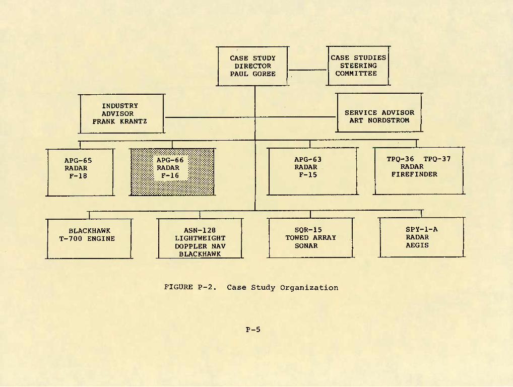
case studies, the organization shown in Fig. P-2 was established.
In some areas where program documentation and records did not exist, the actual
experience and judgement of those involved in the programs were captured in the case
studies. Likewise, in the analysis process, the broad base of experience and judge-
ment of the military/industry executive council members and other participants was
vital to understanding and analyzing areas where specific detailed data were lacking.
This document records the program activities, details and findings of the Case
Study Working Group for the specific program as indicated in Fig. P-2.
Without the detailed efforts, energies, patience and candidness of those inti-
mately involved in the programs studied, this case study effort would not have been
possible within the time and resources available.
The views expressed within this document are those of the working group only.
Publication of this document does not indicate endorsement by IDA, its staff, or
its sponsoring agencies.
P-4
CASE STUDY DIRECTOR
CASE STUDIES STEERING
PAUL GOREE COMMITTEE
INDUSTRY ADVISOR
FRANK KRANT SERVICE ADVISOR ART NORDSTROM Z
1 1 1 1
APG-65 RADAR F-18
M APG-66 ?**;:*?:;::: ::*:;: RADAR SSfe:::::::::: m F-16 im^M
APG-63 RADAR F-15
TPO-36 TPO-37 RADAR
FIREFINDER
1 1 1 1
BLACKHAWK T-700 ENGINE
ASN-128 LIGHTWEIGHT DOPPLER NAV BLACKHAWK
SOR-15 TOWED ARRAY
SONAR
spy-i-A RADAR AEGIS
FIGURE P-2. Case Study Organization
P-5

F-16 APG-66 FIRE CONTROL RADAR
RELIABILITY AND MAINTAINABILITY CASE STUDY
40A/12

FOREWORD
This case study represents an assessment of the predominant factors that most strongly
influenced the outcome of the F-16 Fire Control Radar Reliability and Maintainability
Program.
Radar systems used within the military and identified as successful programs were
selected for study to determine the factors that most strongly influenced the outcome of
the programs. The case study was directed toward identifying program elements that were
significant influencing factors on reliability and maintainability, documenting the lessons
learned and establishing recommendations for future programs. This study, although directed
specifically toward reliability and maintainability, encompassed a broad view of program
elements and considered the complex interrelationship between contractual arrangements,
management, design, manufacturing, and test and evaluation.
Reports documenting other case studies are published under separate cover. This
report documents the case study for the AN/APG-66 fire control radar used on the USAF F-16
airplane.
Ill
40B/13

F-16 APG-66 FIRE CONTROL RADAR WORKING GROUP
AIR FORCE;
CART. BOB RUSSELL - F-16 PROGRAM OFFICE. RELIABILITY & MAINTAINABILITY ENGINEER CARROLL WIDENHOUSE - RELIABILITY & MAINTAINABILITY ENGINEER. AF/ALD LTC LARRY GRIFFIN - DIRECTOR, RELIABILITY & MAINTAINABILITY. AF/ALD
GENERAL DYNAMICS;
BILL BOOTON - MANAGER. SENSORS. PROCESSING AND DISPLAY SYSTEMS NORMAN BUTLER - ENGINEERING CHIEF. RELIABILITY MARVIN JOHNSON- ENGINEERING SPECIALIST. RELIABILITY DAVID PARHAM - SENIOR ENGINEER. MAINTAINABILITY BILL SUMMERS - MANAGER. RF SYSTEMS
WESTINGHOUSE:
IDA;
DICK DOBYNS - APG-66 PROGRAM MANAGER PHIL HATFIELD - MANAGER. FIELD PERFORMANCE EVALUATION NAOMI McAFEE - MANAGER. DESIGN ASSURANCE AND OPERATIONS ROY PYLE - SUPERVISOR. MAINTAINABILITY ENGINEER
PAUL 60REE - DIRECTOR. R&M CASE STUDIES MURRAY KAMRASS - RESEARCH STAFF MEMBER TOM MUSSON - CONSULTANT DICK GUNKEL - CONSULTANT GENE KUNZNICK - CONSULTANT
40A/13 V

^5A/3-l
r.ASF STUDY CONTENTS
PAGE
• INTRODUCTION ' I-l
- MISSION NEEDS IA-1
- SYSTEM DESCRIPTION IB-1
- PROGRAM SUMMARY IC-1
- MEASURES OF SUCCESS ID-1
• PROGRAM ELEMENTS II-l
- CONTRACT IIA-1
- MANAGEMENT IIB-1
- DESIGN IIC-1
- MANUFACTURING IID-1
- TEST AND EVALUATION IIE-1
• SUMMARY AND LESSONS LEARNED HI-l
VXl

ABBREVIATIONS
APPRO Air Force Program Resident Office AIS Avionics Intermediate Shop ATP Acceptance Test Procedure
BIT Built-in-Test
CDR Critical Design Review CDRL Contract Data Reguirements List CFE Contractor Furnished Eguipment CMSEP Contractor Management System Evalua-
tion Program CND Cannot Duplicate COD Correction of Deficiencies
DESC Defense Electronics Supply Center DLA Defense Logistics Agency DSP Digital Signal Processor
ECP Engineering Change Proposal ECS Environmental Control System EPG European Participating Governments EOT Environmental Qualification Test ESD Electrostatic-Sensitive Devices ESS Environmental Stress Screening
FAR Failure Analysis Report FCC Fire Control Computer FET Field Effect Transistor FFP Firm Fixed Price FMC Fully Mission Capable FSD Full Scale Development FTM Flight Test Model
GD General Dynamics GFE Government Furnished Eguipment
HAFB Hill Air Force Base HUD Head-Up Display
ILS Integrated Logistic Support (System) INU Inertial Navigation Unit IR&D Independent Research and Development
LCC Life-Cycle Cost LRU Line Replaceable Unit LSI Large Scale Integration
MCL Master Caution Light MFL Maintenance Fault List MFTBF Mean Flight Time Between Failure MHP Multiple Chip Hybrid Package MMH/FH Maintenance Man Hours per Flight
Hour MOT&E Multi-National Operational Test and
Evaluation MRB Material Review Board MRN Material Rejection Notice MTBF Mean Time Between Failure MTBMA Mean Time Between Maintenance
Actions - -
OFP Operational Flight Program
PCB Printed Circuit Board PDR Preliminary Design Review PFL Pilots Fault List PSP Programable Signal Processor
RADC Rome Air Development Center R&M Reliability and Maintainability RAT Reliability Acceptance Test
ix

RGT Reliability RIW Reliability ROT Reliability RTOK Retest O.K.
Growth Test Improvement Warranty Oualification Test
SOW Statement of Work SRU Shop Replaceable Unit STALO Stable Local Oscillator ST Self Test STFF Self Test Fault Flag
TAG TAT TLSC TWT
WEC WUC
Tactical Air Command Turnaround Time Target Logistic Support Traveling Wave Tube
Cost
Westinghouse Electric Corporation Work Unit Code

INTRODUCTION
i-l
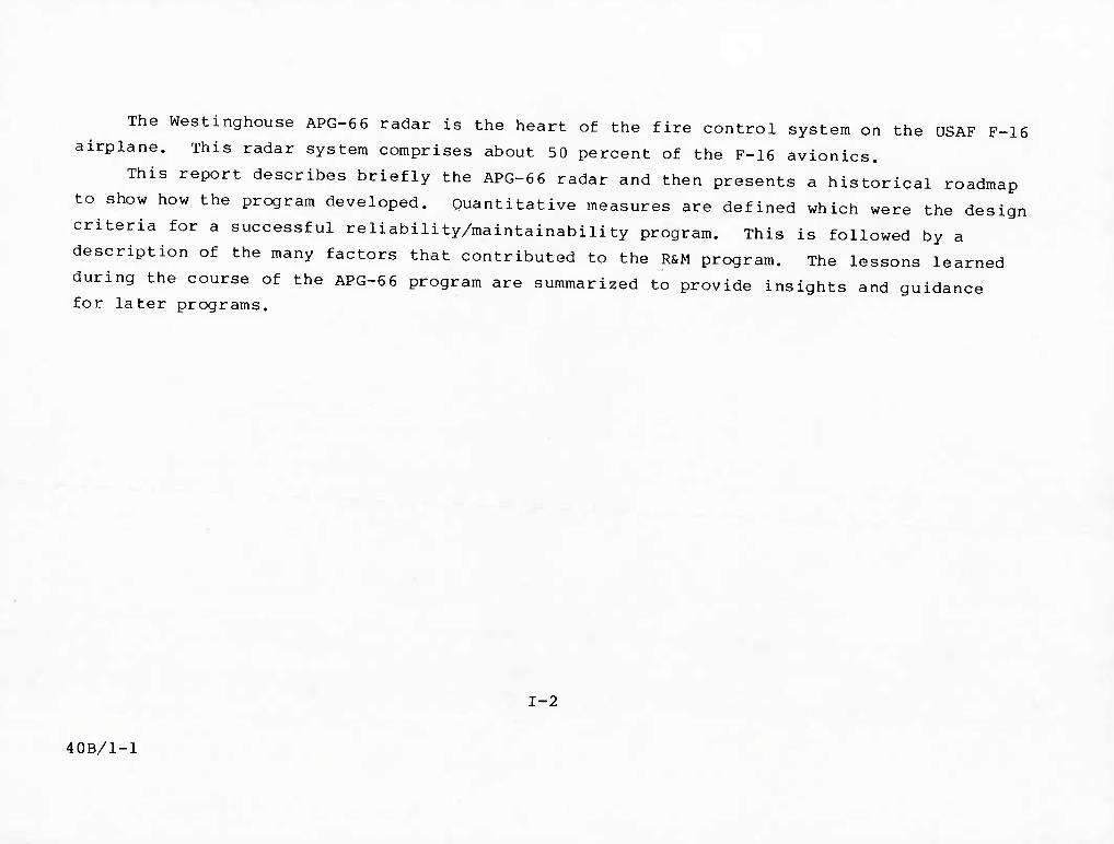
The Westinghouse APG-66 radar is the heart of the fire control system on the USAF F-16
airplane. This radar system comprises about 50 percent of the F-16 avionics.
This report describes briefly the APG-66 radar and then presents a historical roadmap
to show how the program developed. Quantitative measures are defined which were the design
criteria for a successful reliability/maintainability program. This is followed by a
description of the many factors that contributed to the R&M program. The lessons learned
during the course of the APG-66 program are summarized to provide insights and guidance for later programs.
1-2
40B/1-1

INTRODUCTION
• MISSION NEEDS
• SYSTEM DESCRIPTION
• PROGRAM SUMMARY
• MEASURES OF SUCCESS
40A/14
1-3

MISSION NEEDS
lA-l

MISSION NEEDS
The fire control radar (FCR) for the F-16 is a coherent, multimode, digital fire con-
trol sensor designed to provide all-weather air-to-air and air-to-surface modes with advanced
dogfight and weapon delivery capabilities. The air-to-air modes provide the capability to
detect and track targets at all aspect angles and at all altitudes both in the clear and in
the presence of ground clutter. Target information in the air-to-air modes is presented as
synthetic video on a "clean scope" display, both on a head-up display (HUD) and a head-down
display, the Radar/Electro-Optical Display. Air-to-surface modes provide extensive mapping,
target detection and location, and navigational capabilities.
lA-3
40B/19-1

DESCRIPTION OF
THE APG-66
FIRE CONTROL RADAR
IB-l

APG-6 6 SYSTEM COMPONENTS
The F-16 Radar consists of six functional line replaceable units (LRUs) which are
organized for autonomy, logical function, minimum interconnection, ease of maintenance, and
co-production potential.
The six replaceable units are antenna, transmitter, low-power radio frequency (RF)
unit, digital signal processor, the radar computer, and a radar control panel. A digital
multiplex bus system provides a "party line" interface between the radar computer and the
other line-replaceable units, with the exception of the digital signal processor. A separate
high-speed data bus connects the radar computer with the digital signal processor.
All radar LRUs are mounted in the nose of the F-16 aircraft and are accessible from
ground level, except for the radar control panel installed in the cockpit.
The primary means of communication with the other F-16 avionic systems is by use of
MIL-STD-1553B Multiplex System. Video is provided to the cockpit displays in an RS-170
format.
IB-2 40C/1-1

F'16 APG-66 SYSTEM COMPONENTS
A r
Antenna
A
P.S. „
Uniphasor MCV*"- Drlver ^'<^
aam Transmitter
TWT !-*-!
I IProtec- Pulser I ol ' ''°" * 1_ J^on'^1 LVPsT I'O
7\
uiQibus
RCP Power Supply
Mode I Freq.
Range I Prf j
Antenna Scan
7\ rr^
f^Wli-,.Wfl?Mlt Computer
a/c P.S.jCPUl. Inter
h-^1 ' N ,,^L. I Missile "° l"'"-! ■ Me,
A _i_
DSP Bus
dc Inputs Synchro Inputs
Triggers & Timirtg
1 l-Q Bus
b>
BB^S Processor
F-16 Avionics Mux Bus
U^ .Analog to SMS (AIM-9L)
PS
I/O
Syncljronizer
-| r- Proc Scan RS-170 Video
IB-3

The
APG-66 RADAR LINE REPLACEABLE UNITS
1. ANTENNA
The planar array antenna, gimballed in two axes, provides high gain and low sidelobes
over all scan angles. It includes a lightweight balanced electric drive system.
2. TRANSMITTER
The transmitter contains an air-cooled traveling wave-tube (TWT), a solid-state grid
pulser, high voltage power supplies and regulators, and protection and control circuitry,
entire transmitter is solid state, except for the final TWT output tube. The pilot may select
among four of the 16 available APG-66 operating frequencies in any given F-16 aircraft.
3. CONTROL PANEL
The radar control panel in the cockpit is used by the pilot to command the desired radar
channel mode, range scale, scan width, and elevation bar scan. The avionics system can, under
many conditions, assume control of the radar functions .
4. LOW POWER RF _
The low-power radio frequency unit contains a receiver protector, low-noise Field Effect
Transistor (FET) amplifier, receiver, analog/digital converters, stable local oscillator (STALO),
and the system clock generator. All needed analog processing of the radar return signal is
performed in this LRU. The LPRF also provides frequency agility for certain air-to-surface modes,
40C/1-30 lB-4

APG-66 RADAR LINE REPLACEABLE UNITS
Trantmllter Control Panel
fm
Low Power RF Digital Signal Processor Computer
lB-5

APG-66 RADAR LINE REPLACEABLE UNITS
5. DIGITAL SIGNAL PROCESSOR
Clutter rejection and other radar signal processing is performed by the digital signal
processor. Digital radar techniques have been used extensively to replace contemporary
analog hardware. The digital signal processor uses standard integrated circuits mounted in
dual-in-line packages. Large scale integration (LSI) dej,^ices are used where industry
standards and multiple sources exist. Thus, a high circuit density is achieved which
decreases size and weight at a low cost. Custom LSI devices were avoided for cost and
availability reasons in favor of standard devices, which have exhibited reliability maturity.
6. COMPUTER The radar computer configures the radar system for the various operating modes, directs
the digital signal processor to embed symbols in the video output, makes calculations,
routes data to the fire control computer, interfaces with other F-16 avionic systems as
well as other radar LRUs and controls all of the self-test and built-in-test functions of
the radar. Growth provisions have also been made in the F-16 Radar for addition of the
missile illuminator required for the Sparrow (AIM-7) missile. The computer is equipped
with 48,000 16-bit words of programmable, semiconductor read-only memory. Temporary scratch
pad memory requirements are met using volatile, semi-conductor random access memory.
Memory reserve exists for introduction of new features and modes.
40C/1-31 lB-7

F-16 APG-66 RADAR INSTALLATION
The installation of the APG-66 is shown in the accompanying figure. The Radar Control
Panel is installed in the cockpit. The other LRUs are installed in the forward portion of
the aircraft. The forward-installed LRUs other than the antenna are mounted in a rack
which provides interface with the airplane. Key APG-66 parameters are shown in the table
in the upper left corner of the figure.
lB-8 40C/1-2

F-16 APG-66 RADAR INSTALLATION
APG-66 RADAR PARAMETERS
VOLUME WEIGHT FREQUENCY RELIABILITY MAINTENANCE
ELECTRONIC PARTS COOLING INPUT POWER RANGE SCALES ELEVATION COVERAGE ANTENNA AZIMUTH SCAN POWER OUTPUT AVERAGE
3-6 FT3 (.102 M3) 295 LB (134.3 KG) X BAND PULSE DoPPLER 97 HOUR LAB DEMONSTRATED MTBF <.05 HR MCTT McT (MEAN) AND <1.0 HR MCTT McT (MAX) 9500 AIR COOLED AT 12 LB/MIN 358D VA. 400 Hz. 245 WDC 10. 20. 40. 80 NMi 1. 2. OR 4 BAR ±10. ±30. ±60 DEGREES ~200w
Radar Antenna J Radar Transmitter-J
Radar Control Panel
41/5
Left-Hand Side
Right-Hand Side
Dedicated Growth: • CW Illuminator • Etc
i-LPRF DSP Computer
lB-9

F-16 APG-66 SYSTEM PARAMETERS
This table presents a number of the physical characteristics of the APG-66 radar by
LRU early in its development program. These bogies are allocations made by WEC to achieve
system objectives. Subsequent development efforts led to changes in these parameters that
are not reflected here. These parameters are as of May 29, 1976 only.
40B/1-56 lB-10

F-16 APG-66 SYSTEM PARAMETERS (AS OF MAY 29. 1976)
5 5
c
§ >
a
a
!i IH NU
MBER OF
ELEC
TRON
IC
COMP
ONEN
TS (TOTAL) a!
He UJ
O 1 UJ
Is
3 e
h X >- UJ u
l*J
«S UJ
NUMB
ER O
F LRU
CONN
ECTI
ONS
ACTIVE PI
NS/T
OTAL PI
NS
?a «8
2 :^B INPUT
POK£R
(H)
28 VDC
WORS
T CA
SE
a.
a>
X
u. BC ac
52 i3 ee Z UJ u —• a. • _j f^
o at O -J •>
u. aa
is UJ =>
IE
• 0 U 0 3 V* 0 tJ X W H ^
■H W 81 ». (!.». W
ac <^ •^ C
■3"
u^ c\t 4n O r- O
a p.
m m *^ fi m ■9 w
*j a • 3
• w o H
W f ■
■ «t A. «
m
c m
•s
A'lTENilA Aa a.9 NA Ui 733 4 0 Sl| 10/13 Pwt 5/10 650 0 0.75 176; 0.34 18.4 317 192 900
BOG 57.2 KA 2C5 749 0 0 Sig 18/37 Pwr 10/18
657 0 0 2877 0.33 18.8 335* 210 2000 .
TRANSMITTER An (S.« 1.2 «9 750 11 SKA 1 TWC
3 Slg 15/22 P-r 7/10
1424 29 3.6 1366 1.123 19.9 1227 1227 1400
BOG iZA 1.2 48 746 10 2 Slg 16/20 Pwr 11/18
1269 48 2.S 2il61 1.75 20.0 1227 1227 2500 ..
LPRF ACT (7.i .9] 322 1620 62 4 Sl| 60/79 P«r 7/10
603 106 3.6 755 0.7106 29.5 582 582 1200
BOC 37.7 .i 219 1781 40 3 Slg 74/81 Pwr 10/13
660 86 1.9 1199 0.72 25.? 579 579 2500
COMPUTER (IIICL PWR. SUP)
ACT I>.4 .35 760 1100 1 1 Slj 68/79 Pwr 8/10
209 0 1.4 1353 0.5035 13.x 289 289 900
BOC 27.4 .51 1015 1755 0 0 Slg 88/97 P«r 39/43
361 34 1.5 1071 0.50 15.1 284 284 1800 '
DSP {INCL INVERTER)
Aa ii.i, .95 2738 3300 0 3 Sl| 68/100 Pwr 5/10
963 0 4.3 491 0.5106 21.0 900 900 1250
BOC 52.7 .9 3083 3503 0 3 Slg 90/100 Pwr 6/18
857 0 3.8 338 0.52 21.5 900 900 2500
RACAR CONTL. PNL. Aa 3.5 .01 34 95 0 0 Sit 12/22 Pwr 8/13
3 12 - 12048 0,47 2.0 12 0 150
BOG 3.5 .08 65 112 0 0 Slg 6/22 Pwr 13/22
0 17 0 13250 0.45 1.7 20 0 700
RACK 1 CABLE 1 WAVEGUIDE ASSY.
ACT 17.3 ,3S 0 13 0 2 Slg 41/55 Pwr 28/32
0 0 - 4808 - 34 0 0 650
BOG U.7 NA 0 0 0 0 Slg 70/128 Pwr 3y43
0 19 0 - - 2.6 0 0 1000
SrSTEH TOTAL
ACT 2li.< t.Oi 4039 1331 79 12 Sl| 274/370
Pwr 68/95 3995 147 12.1 176 0.7008 107.4 3327 3190 6450
BOG 258.2 3.59 4725 1647 SO a Sl| 362/495 Pwr 122/175 3373 204 10.0 17R 0.75 10t.4» 3345 3200 13000
lB-11
N/A Not Ap|illcabl< • wicci HI dliiliitclon tncludtd.
>• Including 1.2 for ajiembly ind ten.

APG-66 RADAR SYSTEM EVOLUTION
The chart depicts the evolution that led to the development of the modular APG-66
radar. Westinghouse began design and development activity in 1971 for a new series of
modular radar, designed to a cost. The WX series of radars, and in particular the WX200,
used the pulse doppler principle and advanced digital techniques. Demonstration of these
balanced design techniques led directly to the subsequent balanced design and development of the APG-66 in July 1974.
lB-12
40C/1-3

AN/APG-66 Westinghouse Advanced Radar Systems Evolution
1968 1969 1970 1971 1972 1973 1974 1975 1976 1977 1978 1979 1980 1981 1982 1983 1984
> F-4E APQ-120 / LRU-1 / Peace Rhine
r F-4J/AWG-10/11/12 / AWG-10A / . AWG-10B ^
F-15 EiVIR WX-200 Mod Radar F-4E/J APG-66J } F-16/APG-66
Electronically Agile Radar (EAR)
E-3A/AWACS
IB-13

PROGRAM SUMMARY
ic-i
F-16 APG-66 PROGRAM SUMMARY
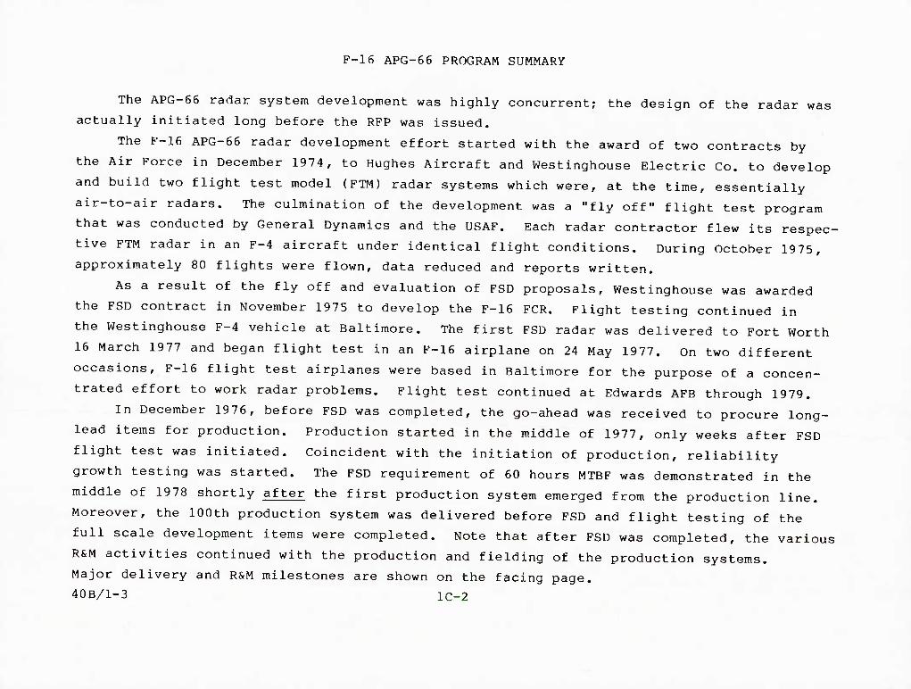
The APG-66 radar system development was highly concurrent; the design of the radar was
actually initiated long before the RFP was issued.
The F-16 APG-66 radar development effort started with the award of two contracts by
the Air Force in December 1974, to Hughes Aircraft and Westinghouse Electric Co. to develop
and build two flight test model (FTM) radar systems which were, at the time, essentially
air-to-air radars. The culmination of the development was a "fly off" flight test program
that was conducted by General Dynamics and the USAF. Each radar contractor flew its respec-
tive FTM radar in an F-4 aircraft under identical flight conditions. During October 1975,
approximately 80 flights were flown, data reduced and reports written.
As a result of the fly off and evaluation of FSD proposals, Westinghouse was awarded
the FSD contract in November 1975 to develop the F-16 FCR. Flight testing continued in
the Westinghouse F-4 vehicle at Baltimore. The first FSD radar was delivered to Fort Worth
16 March 1977 and began flight test in an F-16 airplane on 24 May 1977. On two different
occasions, F-16 flight test airplanes were based in Baltimore for the purpose of a concen-
trated effort to work radar problems. Flight test continued at Edwards AFB through 1979.
In December 1976, before FSD was completed, the go-ahead was received to procure long-
lead items for production. Production started in the middle of 1977, only weeks after FSD
flight test was initiated. Coincident with the initiation of production, reliability
growth testing was started. The FSD requirement of 60 hours MTBF was demonstrated in the
middle of 1978 shortly after the first production system emerged from the production line.
Moreover, the 100th production system was delivered before FSD and flight testing of the
full scale development items were completed. Note that after FSD was completed, the various
R&M activities continued with the production and fielding of the production systems.
Major delivery and R&M milestones are shown on the facing page.
40B/1-3 lC-2

F-16 APG-66 PROGRAM SUMMARY
1975
^ GO AHEAD BRASSBOARDi
DEMO
1976 1977
FSD
PRODUCTION
RSM MILESTONES
DESIGN^ FAB AND TEST
FLYOFF A A^'^-'AIR-TO-GROUND ADDED
S FSD GO AHEAD
1978 1979 1980
DESIGN AND DEVELOPMENT 1 r-r- Ist FSD SYSTEMA A 12th SYSTEM I
FSD FLIGHT TEST
ALONG LEAD GO AHEAD
A A PDR CDR
A DSARC-I
IZ
1981 1982
ATWT DEMO
1st SYSTEM
50th ^SYST^,
PRODUCTION
100th SYSTEM
A IOC %
500th ASYSTEM
7 1000th A SYSTEM
1300th ^SYSTEM
BLOCK 10 UPDATE
IIA DSARC-IIIB
PCA 60 HOURS MTBF A_(FSD RQT.)
STARTED COMPLETED
ATHERMAL VERIFICATION
DEMONSTRATED
97 HOURS MTBF A DEMONSTRATED
^ STARTED
RAT
COMPLETE i
lC-3

F-16 APG-16 RADAR FSD RELIABILITY SCHEDULE
Planned versus actual FSD reliability test schedules and their relationship to major
program milestones are shown on the facing chart. Differences in planned and actual test
start dates were due primarily to unavailability of hardware.
The number of systems used for reliability growth and development reliability
qualification tests was also impacted by asset availability.
40C/1-33
lC-4

F-16 APG-66 RADAR FSD RELIABILITY SCHEDULE
PLANNED -- = = ACTUAL
1976 1977 1978
TWT RELIABILITY 3 UNITS TEST
3 UNITS
11 1 = m ^ -^
it
6
RGT I] UNITS
1 UNIT
5 10
7 12
THERMAL ANALYSIS AND VERIFICATION
2 3 3
RQT 3 UNITS
2 UNITS
7 10 "I
3 it 6 = \\==
#1 #2
GO AHEAD 11/2^/75 A
PDR it/76
CDR 6/8-11/76
FIRST F-16 RADAR FLIGHT 5/27/77
RADAR PCA it/24/78
A
AA
A
A
itl/38 lC-5

MEASURES OF SUCCESS
ID-l

MEASURES OF SUCCESS
Program success can be measured in terms of reliability and maintainability character-
istics and their effect on field operations and supportability. Reliability and maintain-
ability emphasis throughout the AN/APG-66 program, from design inception through field use,
have resulted in high mean-flight-time-between-fallures (MFTBF) and low maintenance manhours
per flight hour (MMH/FH) accompanied by reduced support costs and increased operational readiness in field use.
40C/1-4
lD-2

MEASURES OF SUCCESS
FIELD RELIABILITY - MFTBF = 65 HOURS
OPERATIONS AND SUPPORT COST - LOWER THAN PREVIOUS RADAR
FIELD MAINTAINABILITY - MATURE PREDICTION ACHIEVED
PERCENT OF FLIGHTS WITH NO RADAR FAULTS - GROWTH FROM 35 TO 89%
DEPOT REPAIR TURNAROUND TIMES LESS THAN 20 DAYS
OPERATIONAL READINESS EXCEEDING 98% FULLY MISSION CAPABLE (FMC)
41/6 lD-3

RADAR SET FIELD MFTBF EXCEEDS PREDICTION BY 45%
This figure shows the Mean Flight Time Between Failure (MFTBF) for the APG-66 radar,
installed in production F-16 aircraft, operated by Air Force personnel in service environ- ments.
The measured field MFTBF is a 3-month moving average plotted monthly and compared to
the predicted MFTBF growth for the F-16 APG-66 radar. This MFTBF is based on Air Force AFR
66-1 data for the F-16 Tactical Air Command (TAC) fleet and is defined as
MFTBF = MTBMATYPE 1 = ___^_^_ FLIGHT HOURS
GROUND TYPE 1 FAILURES + FLIGHT TYPE 1 FAILURES
where Type 1 (inherent) failures are as defined in AFR 800-18.
The predicted growth curve was developed (during FSD) as an indicator to determine if
the radar would achieve its mature predicted MFTBF.
The growth in measured field MFTBF is the result of an aggressive failure analysis and
corrective action emphasis implemented for reliability testing, manufacturing tests and
field operations during the first 150,000 hours of flight.
The measured MFTBF for the six months ending in August 1982 is 65 hours and is 45%
above the mature predicted MFTBF of 45 hours for the radar. - - - -
ID-4
40B/15-1

80-
RADAR SET FJFID MFTBF* EXCEEDS PREDICTION BY ^5%
• AIR FORCE AFR 66-1 DATA
• TAC EXPERIENCE
• 150.000 FLIGHT HOURS
• 3 MONTHS MOVING MFTBF
60-
MFTBF IN
HOURS
MO-
20-
n
/
/ /
r^
/ HAh
MEASURED MFTBF
.--^"X^^A/^
PREDICTED MFTBF
GROWTH
^
1 ; z 1 3 n I 2 13 4 1 2 3 4 1 2 13 4 ^ L sz-Tz '
L979 1980 1981 iyxz 1
;-AUG '82 MFTBF
Jo ABOVE lEDICTIO
FLIGHT HOURS *MFTBF = MTBMAjYPE 1 = GROUND TYPE 1 FAILURES + FLIGHT TYPE 1 FAILURES
WHERE TYPE 1 (INHERENT) FAILURES ARE AS DEFINED IN AFR 800-18
41/14 ^°-^

IMPROVED RELIABILITY RESULTS IN LOWER O&S COSTS
The sensitivity of operations and support cost due to improved radar reliability is
presented on this chart. The operations and support cost includes replenishment spares;
organization-, intermediate- and depot-level maintenance labor and material costs for the
F-16 APG-66 radar. Program characteristics, upon which the O&S cost estimate is based,
reflect an F-16 program of procuring 1388 aircraft flying a total of 4,742,322 flight
hours over 15 years. The cost estimates were calculated using a General Dynamics operations
and support cost model for a range of radar system reliabilities from an MFTBF value of 10 to 80 hours.
The curve shows that an operations and support cost savings of $250M could be realized
throughout the life of the F-16 program over the costs that would have been incurred if the
F-16 radar had been a 20-hour MFTBF radar (typical of today's fighter radar). This cost
avoidance will more than offset the up-front cost of added reliability design, testing and
reliability improvement warranty programs that lead to the current high field MFTBF of the APG-6 6 radar.
lD-6 40B/15-2

IMPROVED REllABILITY RESULTS IN LOWER O&S COST
NOTES
$100M O&S COST
8-
7-
6-
5-
4-
3-
2-
1-
OTHER FIGHTER RADAR MFTBF
- 1388 A/C BUY
- 4.742.322 FLIGHT HOURS
- 15 YEARS LIFE
- FY '82 $
- O&S COSTS INCLUDE:
— REPLENISHMENT SPARES
—O.I&D LEVEL LABOR & MATERIAL COSTS
CURRENT RADAR FIELD' RELIABILITY
W 50
MFTBF IN HOURS
60 70 80
41/7 ID-7

APG-6 6 RADAR MMH/FH PREDICTION ACHIEVED
Excellent maintainability characteristics have been achieved by the APG-66 radar. As
shown in the figure, the APG-66 MMH/FH typically runs under one hour. This is derived
from the Air Force maintenance data collection system AFR 66-1, and applies to TAC exper-
ience with more than 150,000 flight hours. Other than the peaks at the beginning, there
is only one other large peak occurring in summer-fall of 1981. This peak does not reflect
radar maintainability problems but occurred because the F-16 airplane flying activity was
curtailed during this period to modify the airplane's electrical system. Since very few
flying hours occurred during this period and maintenance actions continued, the MMH/FH
increased drastically. However, after full flying schedules were resumed near the end of
1982 the MMH/FH rapidly improved and approached the predicted mature value of 0.5.
The predicted mature value (circa 1977) of MMH/FH for the APG-66 Fire Control Radar-
was 0.56 hours. Attainment of this value was predicated on the achievement of anticipated
system reliability, availability of necessary support equipment and personnel, and compliance
with the recommended maintenance concepts and procedures. This prediction did not include
travel times for maintenance personnel and administrative delay times. Reported field data
includes these additional time parameters. The fact that Air Force AFR 66-1 field data
indicates that this prediction is being met is a conservative estimate of the MMH/FH
measure. These results are based on monthly reports from Hill, MacDill and Nellis Air Force Bases. '
lD-8 40B/1-5

F-16 AP6-66 RADAR MMH/FH PREDICTION ACHIEVED
MMH/FH
FORCE AFR 66-1 TAC EXPERIENCE 150.000 FLT HRS MONTHLY MMH/FH
J F M A M J J A S 0 19 7 9
N D
F-16 FLEET. ELECTRICALX MOD
J F M A M^J J A S 0 N D 19 8 0
J F M A M J J A S 0 N D 19 8 1
*PREDICTION INCLUDE
DOES NOT
EXCESSIVE TRAVEL TIME ADMIN DELAY TIME EXCESSIVE CREW SIZE (E-G-. "ON-JOB- TRAINING")
CANNIBALIZATION
J F M A M J J A S 0 19 8 2
40A-18 ID-9

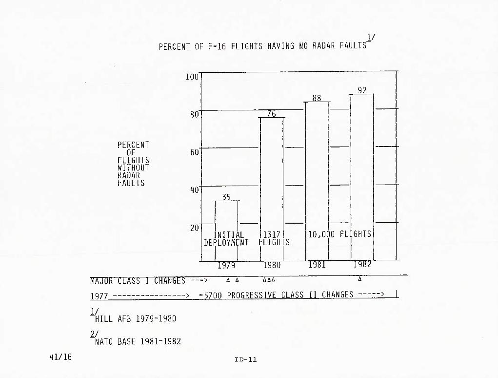
PERCENT OF FLIGHTS WITH NO RADAR FAULTS
Another measure of program success is the steady increase in the percentage of F-16
flights which had no radar malfunction reported. This parameter grew from approximately
35% in 1979 to 92% in 1982. Flights without fault would be even higher if flights which
contained repeat faults (faults which were known but not corrected) were discounted. The
improvement in flights without faults during the 1979-1980 time period is a result of a
number of modifications incorporated during that period. One of the most significant
improvements was General Dynamics ECP 331, which is discussed in more detail in the test and evaluation portion of this report.
lD-10 40B/1-63
PERCENT OF F-16 FLIGHTS HAVING NO RADAR FAULTS" 1/
PERCENT OF
FLIGHTS WITHOUT RADAR FAULTS
100'
80'
60
^0
20'
76
35
NITIAL DEPLOYMENT
1317 FLIGH
88
10.000 FL
92
GHTS
1979 1980 1981 1982
MAJOR CLASS 1 CHANGES —> A"^^ AAA A
2977 > ^5700 PROGRESSIVE CLASS II CHANGES >
1/ "HILL AFB 1979-1980
2/ "NATO BASE 1981-1982
^1/16 ID-ll

REPAIR TURNAROUND TIMES (TAT)
The RIW contract specified that units returned to the manufacturer were to be repaired
and made ready for return to the Air Force within 22 days. Those units manufactured
that were not under the RIW contract were given 30 days for TAT. It will be noted that
except for one short period of time a 20-day turnaround time (TAT) was achieved for the
entire period for both RIW and non-RlW units. This record is better than the records
associated with previous avionic systems and is better than the goals and requirements that
were originally set for this system. Non-RIW units benefited from the repair system set up for the RIW units.
lD-12 40B/1-7 •

40-
35-
F-16 APG-66 RADAR TURNAROUND TIMES (TAT)
BETTER THAN GOALS AND REQUIREMENTS
50-'
45-
30- NON RIW GOAL
MAY JUN JUL AUG SEP
IW (MONTHLY TAT)
NON-RIW (MONTHLY TAT)
OCT NOV DEC JAN FEB MARIAPR MAY
1981
JUN
1982
JUL AUGlSEP OCT NOV1 DEC
40A/16-1 ID-13

OPERATIONAL READINESS
The data on this figure represent operations at three Air Force bases. Nellis AFB is
represented in the top panel, while Hill and MacDill AFBs are jointly represented in the
bottom panel. The charts show the proportion of aircraft in each set that had fully mis-
sion capable radars on each of the calendar days shown in the abscissa. It should be
noted that for all bases represented, the radar FMC rate was in the range of 98-99 percent
for the most recent six months shown. This trend is expected to continue.
ID-14
40B/1-8

F-16 RADAR SUPPORTABILITY
iJ J r. 1.
< <
z D /)
F-16 RADAR SUPPORTABILITY
100-T—r COMBAT READINESS
FEB UAR APR WAY JUN JUL AUC SEP OCT NOV DEC JAN FEB UAR APR UAY JUN JUL AUC SEP OCT NOV DEC JAN FEB 1981 1982
KILUUACOia AND NELL IS AFB'S
lD-15

PROGRAM ELEMENTS
ii-i

j , . PROGRAM ELEMENTS
Many factors contributed to the results of the APG-66 radar program. The key
development factors have been divided into five groups. We must caution, however, that
although this grouping may assist in this exposition, these elements are not independent
of each other and in fact have large overlaps. The more significant of these overlaps are
identified and described in the pages that follow.
40B/19-2 II-2

41/8
PROfiRAM ELEMENTS
CONTRACT
MANAGEMENT
DESIGN
MANUFACTURING
TEST AND EVALUATION
II-3

^Qk/V
CONTRACT
STRUCTURE
I & Ti REQUIREMENTS
INCENTIVES
SOURCE SELECTION
LCC
IIA-l
STRUCTURE—CONTRACTUAL RELATIONSHIPS
The contractual relationship that results from the radar procurement being contractor
furnished equipment (CFE) enjoys some flexibility over a government furnished equipment
(GFE) procurement during the development period. Not only does the flexibility exist in
the technical area but also in the program management efforts. Two examples illustrate these points.
In the technical area, the prime/sub interface is such that problem solving can be
accomplished on either side of the interface and still be timely and in scope; that is, no
additional cost to the government. For instance, a software filter to correct a problem
could be either in the CFE procured radar computer (GD responsibility) or in the fire con-
trol computer (GD responsibility). The decision can be influenced not only by the techni-
cal consideration but also the cost and program schedule impact. If the interface were
between GFE radar and CFE avionics, then the flexibility is severely limited and any
problem on the GFE side of the interface results in an out of scope change on the CFE side of the interface.
An example of a programmatic problem might be late delivery of radar equipment from
the supplier such that the installation into the airplane would be out of the planned work
station. With a CFE contract GD could consider the cost impact as in-scope, whereas with
GFE late delivery could be out-of-scope and subject of a cost claim to the government. '
IIA-2 40B/1-10

■STRUCTURE -- nONTRACTUAL KHATIQNSHIPS
CONTRACT INTERFACE SIMPLICITY
FREEDOM TO EFFECT CHANGES WITHIN SCOPE
FLEXIBILITY FOR MANAGEMENT DECISIONS
EXAMPLE;
1. GD HAD TOTAL WEAPON SYSTEM VIEW- DIRECTED OTHER SUPPLIERS
TO MAKE CHANGE TO HELP SOLVE PROBLEMS WITH RADAR INTEGRATION
2. RADAR SPARES-DIVERTED FROM GD BANK EARLY IN PROGRAM-
41/9 IIA-3

REALISTIC REQUIREMENTS
Radar requirements were derived from the overall weapon system requirements. By
defining requirements from the "top down," the radar specification represented a firm,
practical performance level. The statement of work (SOW) to WEC contained a requirement
for verification through demonstrations. The design approach was formally documented and contractually approved by GD.
The contract to Westinghouse Electric Corporation (WEC) from GD included a specifica-
tion (16ZE-009) that laid down the requirements for the F-16 radar. These were firm require-
ments, not goals, and were derived through a balanced design based on experience from
previously-designed radars. The requirement was considered stringent yet possible to achieve at that time.
Other requirements included operating in an environment with 100% relative humidity
over a range of temperatures from -40°F to +70°C, to include sand and dust. At the 0-level
only external cleaning and wiping was allowed. Removals at the 0-level were to be rapidly
accomplished by one man using standard tools. The antenna was the one allowable exception
because of its weight. No adjustments, alignments or calibrations were allowed at the O
level. Mechanical boresighting requirements were such to permit replacement of the antenna without further realignment.
The aircraft ready condition was specified as meeting performance requirements after
seven days without maintenance, checkout or flight. For ease of maintenance at the l-level,
functionally related parts were to be grouped within common SRUs with no adjustment required
when replacing an SRU. Also, it was to be made impossible to install equipment incorrectly,
either mechanically or electrically, by using methods other than tubing shape, color coding or labeling.
IIA-4
40B/1-11

REALISTIC REQUIREMENTS ESTABLISHED
• DEFINED IN SPECIFICATION 16 ZE 009
- REQUIREMENTS FIRM. NOT GOALS
- DERIVED THROUGH A BALANCED DESIGN
- DETAILED COMPARABILITY ANALYSIS
- STRINGENT BUT NOT IMPOSSIBLE
• SPECIFIC LINE ITEMS IN SOW AND CDRL
- VERIFICATION THROUGH DEMONSTRATIONS
- APPROACHES FORMALLY DOCUMENTED AND
CONTRACTUALLY APPROVED
41/10 . iiA-5

CONTRACTOR INCENTIVES
Contractor motivation was provided by various incentives in the contract. Keeping
the costs to a minimum was encouraged by the cost sharing arrangement. Various award fees
were provided for achieving certain performance goals. With the CFE contractual arrange-
ment many of these incentives were passed on directly to the radar supplier.
A dynamic, continuing incentive was the reliability improvement warranty (RIW) program
where the supplier was constantly looking for ways to improve the reliability/maintainability
performance of the equipment. The supplier was given the freedom (from a configuration
management standpoint) to process and incorporate RlW-type changes. With the supplier
functioning as the depot for the production equipment, high visibility was afforded to
Westinghouse in areas which could benefit from RlW-related changes.
While there was an award fee for completing FSD RQT and production RQT early. Westing-
house received neither tee since the tests ended in a reject decision in the time allotted
for the award. However, the incentive was present and Westinghouse did attempt to meet the
award criteria for the tests. As a result of the RQT failure corrective actions were
incorporated early that matured the radar faster than would have otherwise happened.
A significant motivation was the correction of deficiencies (COD) clause of the contract
which basically required the contractor to fix problems at his own expense that did not
meet the requirements of the specification. ^ ^' ^ ^ ~ ^ ^
The developing of high quality equipment is always helpful in maintaining a good
company image and the opportunity for future sales. In the case of the F-16, this was
especially true, since the airplane was being marketed throughout the world. High relia-
bility from the radar would serve to increase its competitiveness with other contenders.
This type of contractor incentive may be the most powerful force at work in motivating
companies to produce reliable products. In addition, the modular APG-66 radar was a good
building block for other radar programs like DIVAD and the B-lB.
40B/1-12 IIA-6

INCENTIVES WERE IMPORTANT TO PROGRAM SUCCESS
• FORMAL
- COST SHARING ABOVE/BELOW TARGET
- AWARD FEES-DESIGN TO COST/RQT
- CORRECTION OF DEFICIENCIES
- RELIABILITY IMPROVEMENT WARRANTY
• OTHER
- ADDED SALES _
- PRIDE/IMAGE
41/11 11 A-7

COST SHARING
The AF contract with GD was a firm fixed price contract (FFP) with cost sharing. If
full-scale development costs went above or below the target, the Air Force and the contrac-
tor shared in the ratio of 85/15 percent, respectively. If production costs went above or
below the target, the sharing ratio was 60/40 percent. There was a cost floor and a cost
ceiling also. Above the ceiling all costs were assumed by the contractor, and below the
floor all costs were paid by the Air Force.
This is the classic FFP structural format; as the contractor risks are reduced, he is
expected to assume more liabilities of cost sharing.
In a CFE program the contracts are compatible between the USAF and GD as well as
between GD and WEC. Therefore, the incentives and cost sharing exist at both contractual
levels.
IIA-8
40B/1-14

FIRM FIXED PRICE CONTRACT WITH COST SHARING — A MAJOR INFLUENCING FACTOR
PROGRAM COST
i|l/15
ABOVE CEILING
CEILING (127.5%)
ABOVE TARGET
TARGET (100%)
• BELOW TARGET
FLOOR ( %)
TW PRODUCnON
ALL COSTS ASSUMED BY CONTRACTOR
COSTS SHARED 85%/157
(USAF/CONTRACTOR)
UNDERRUN SHARED 857/15%
(USAF/CONTRACTOR)
COSTS SHARED 60%/40%
(USAF/CONTRACTOR)
UNDERRUN SHARED 60%/40%
(USAF/CONTRACTOR)
ALL COSTS ASSUMED BY USAF
• COST SHARING PASSED FROM
/ USAF TO GD
/ GD TO WEC
IIA-9

RELIABILITY IMPROVEMENT WARRANTY (RIW)
In an attempt to further motivate the contractor after he won the contract award, the
Air Force included in the contract an option to exercise RIW provisions.
Twelve F-16 LRUs were selected as "control LRUs." These were selected because they
were expected to contribute at least 50 percent of the F-16 logistics support cost. The
proposed contract provisions would permit the government to select any or all of the 12
LRUs for the RIW option. The government could also select an RIW with an MTBF guarantee.
A firm fixed-price option was obtained from the contractor for these options.
During 1976, the 12 control LRUs were subjected to cost analysis, and the RIW option
was extended to the aircraft planned to be procured by the European Participating Govern-
ments (EPG). The contract was subsequently signed with CD in 1977 for RIW coverage of
nine LRUs for all five EPG nations participating in the Multinational Fighter Program. In
addition, two of the LRUs, the radar transmitter and the HUD Processor, were to have MTBF
guarantees. The following table presents the list of equipment selected for the RIW pro-
gram. Note that all five radar LRUs were selected for RIW coverage with one LRU (radar
transmitter) requiring an MTBF guarantee.
IIA-10 40B/1-15

EQUIPMENT SELECTED FOR THE F-IB RIW PROGRAM
WUC
1^1 AAO
74BC0
74BA0
74DA0
7^4 ACO
74AD0
74AF0
74AB0
74AA0
NOMENCLATURE
FLIGHT CONTROL COMPUTER
HEAD-UP DISPLAY (HUD) PROCESSOR*
HEAD-UP DISPLAY (HUD) PILOT DISPLAY
INERTIAL NAVIGATION UNIT (INU)
RADAR TRANSMITTER*
RADAR SIGNAL PROCESSOR
RADAR COMPUTER
RADAR RECEIVER
RADAR ANTENNA
MANUFACTURER
LEAR-SIEGLER INDUSTRIES
MARCONI AVIONICS. LTD-
MARCONI AVIONICS. ETC
SINGER-KEARFOTT DIVISION
WESTINGHOUSE ELECTRIC
WESTINGHOUSE ELECTRIC
WESTINGHOUSE ELECTRIC
WESTINGHOUSE ELECTRIC
WESTINGHOUSE ELECTRIC
THE WARRANTY APPLIES TO ALL UNITS INSTALLED IN THE FIRST 250 USAF AND THE FIRST
192 EPG PRODUCTION AIRCRAFT AND TO SPARES PROCURED FOR SUPPORT OF THESE AIRCRAFT^
RIW WITH MTBF GUARANTEE
40A/10 IIA-11

RIW FEATURES
The nine LRUs were warranted for a period of four years or a total of 300,000 aircraft
flying hours, whichever occurred first. The four-year period began with the delivery of the
first production aircraft in January 1979. In case less than 250,000 hours of flying had
been accumulated at the end of the four-year period, the price of the contract was to have
been adjusted downward in accordance with a formula specified in the contract. The table
opposite shows the major features of the RIW contract.
IIA-12
40B/1-16

MAJOR FEATURES OF THE F-16 RIW CONTRACT
CHARACTERISTIC PFSCRIPTION
UNITS COVERED
AIRCRAFT
COVERAGE PERIOD
CONTRACT TIME
AIR FORCE LOGISTICS MANAGER
PARTICIPATING COUNTRIES
CONTRACTOR
PRICE
MTBF GUARANTEE
CONTRACT PRICE ADJUSTMENT FOR FLIGHT HOURS SHORT- FALL
TURNAROUND-TIME REQUIREMENT
FAULT ISOLATION AT BASE
NINE DIFFERENT LRUS (5 RADAR)
250 USAF AND 192 EUROPEAN F-16AS AND F-16BS
FOUR YEARS OR 300,000 FLYING HOURS (WHICHEVER OCCURS FIRST)
PRIOR TO FULL-SCALE PRODUCTION
OGDEN AIR LOGISTICS COMMAND (ALC)
UNITED STATES. BELGIUM. DENMARK. NORWAY, AND THE NETHERLANDS
GENERAL DYNAMICS (PRIME) WITH FOUR SUBCONTRACTORS
RANGE FROM 2% TO 6% PER YEAR OF LRU COST
RADAR TRANSMITTER AND HUD PROCESSOR MUST DEMONSTRATE 318 AND 500 HOURS, RESPECTIVELY, BY THE END OF THE WARRANTY
APPLICABLE IF FLYING HOURS ARE LESS THAN 250.000 IN 4 YEARS
22-DAYs AVERAGE (DEPOT)
YES
40A/11 IIA-13

SOURCE SELECTION
Reliability and maintainability were key factors in the RFP, which specified a support-
able radar system with the following supportability characteristics: accessibility, ST/BIT,
I-level testability/repairability, etc. Considerations included lower ownership costs of
the radar by reducing downtime and by requiring fewer maintenance resources.
In source selection and evaluation over a 3-month period, reliability engineering
provided four full-time members: two for reliability problems, one for RIW, one for parts
control and standardization. In addition, life-cycle cost and thermal design engineering
provided at least one member. Maintainability engineering provided two members. Contractor
inquiries and modification requests were sent to applicable functional engineering groups
for additional information for evaluation. These members were also part of the team at ■ negotiations with each competing vendor and required a meeting from each competitor relative
to the design and testing of TWTs, as well as the requirement for random vibration. Here
again, requirements were reaffirmed and failures defined. Reliability was a key factor in all computations of life-cycle costs.
IIA-14 40B/1-17

SOURCE SELECTION
R&M KEY FACTORS IN RFP
COMPETITION FORCED ACCEPTANCE OF STRINGENT REQUIREMENTS
CONTRACTOR PERCEIVED R&M A KEY FACTOR
REQUIRED RIW/MTBF GUARANTEE COMMITMENT
R&M EVALUATED ON AN EQUIVALENT BASIS WITH OTHER TECHNICAL FACTORS
R&M PRIMARY MEMBERS OF SELECTION COMMITTEE
41/12 IIA-15

LIFE-CYCLE COST
Reliability and maintainability are driving forces in life-cycle cost. A major concern
in the APG-66 radar development program, relative to LCC, was the TWT. Problems identified
on earlier radar programs led to this concern. As a result, separate tests for the TWT
were required in addition to the design requirements for simplicity, ease of maintenance
and reliability. Data submitted by WEC in response to the RFP were analyzed by General
Dynamics and the Air Force using cost models specifically designed to measure LCC.
IIA-16 40B/1-19

LIFE-CYCLE COST — AN IMPORTANT CONSIDERATION
DRIVING FORCE
- RIW/TLSC COD OPTION
- CONTRACTUAL RADAR R8M REQUIREMENTS
SPECIFIC REQUIREMENTS FOR ANALYSIS
SERVED AS BASIS FOR COST INCENTIVES/DESIGN TO COST
INFLUENCED DESIGN TO OPTIMIZE R&M
41/13 iiA-17

MANAGEMENT
IIB-l

MANAGEMENT
Management is the second of the five areas identified as important to producing high
quality military equipment. The three major facets of management shown are discussed in the pages following.
IIB-2
40B/1-21

MANAGEMENT
• ORGANIZATION
• CONTROL & EMPHASIS
• SUBCONTRACTORS/SUPPLIERS
41/18 IIB-3

MANAGEMENT
Management commitment to and involvement in reliability and maintainability objectives
set the stage for success early in the program. A management level organization was
structured with Support Requirements/Q&RA Managers and RIW Managers reporting to Vice
Presidents at General Dynamics and Westinghouse while working directly with their respective
Radar Program managers.
The reliability and maintainability management functions provided visibility and timely
information for management control. Aggressive and informed management emphasis assured
effective integration of reliability and maintainability considerations into the total
program.
IIB-4
40B/1-22
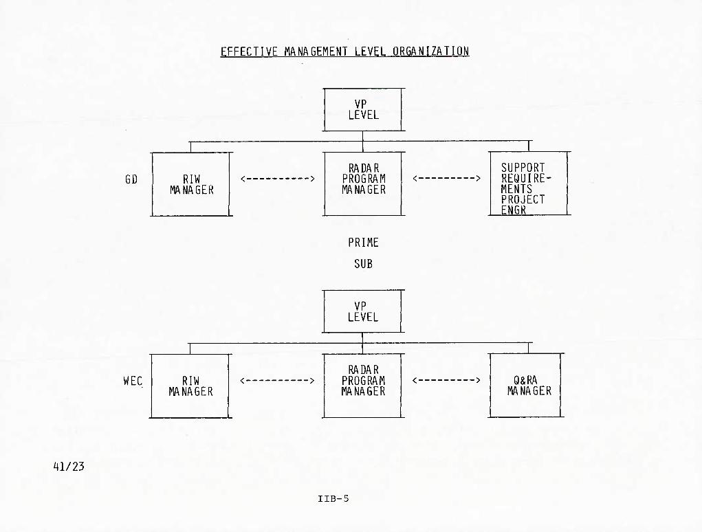
EFFECTIVE MANAGEMENT LEVEL ORGANIZATION
GD
VP LEVEL
RIW MANAGER
RADAR PROGRAM MANAGER
/ — __w**«»N SUPPORT REQUIRE- MENTS PROJECT ENGR
<"""■""""""""">
PRIME
SUB
WEC
VP LEVEL
RIW MANAGER
RADAR PROGRAM MANAGER
• _«•«*•■ — — — — s Q&RA MANAGER
41/23
IIB-5

O&RA ORGANIZATION
This chart shows the quality and reliability assurance organization at WEC. The
depth of the organization and how it is tied into the system program manager at the appro-
priate level is reflected.
IIB-6
40B/1-23

lUIANAOER tTANDARDIZINQ LABORATORY
W.W.HILL
CdibntlM Syitim PoUcy K Dkacllo* Priclilcii Muturtminti SiHMltr* CaltinllM Trtciiblllly Ctlbnllon StivlcM Cuitgnuf InlirUct MiuurmMiil Divtiopminl Miuumninl Conwltitlon NBS LUIwii
MANAGER DUALITY
ENQINEERlNQ
T.H. HART
OkRA Pfoinffl MMIMI
Duality PoHcy Oualliy tnftm Hum Ouillty PractduiM t DinclKfM Ouillty tpwHkillaii Imwyciuibii
ft InptofMnuIlM Ouillly Tninini Qtitlily RtCNdi Govt Rtf. lUboii Wwlmuntlilp iMnitrit Ouillly PMlMnuKt Dm t VbUiUlty SEAT Eii|lnHrln| iKhnolofV Davtloprntfll Induiuy Astochllofis SPKW AtlMllM FiHvn Aiulyilt Quality Aaunnca Eii«l«aafln| Quality t Procan Control R&D tyitama & hocaduiaa AudH Quality Au4IU ElKlrlcal Partormanct
Evalualloo En|l<wafln| MRB Dbpeillloo S Cstractlva Action Tachnolofy Arat Eaflnaarini Piogram QuaUty Enfintailni
MANAQER QUALITY AND
RELIABILITY ASSURANCE
R.TO«M$HEND,JR.
ENQINEERlNQ MANAGER
SYSTEMS EFFECTIVENESS
VJ). MARDNE
HaltablUty t MahitalmbllllY 0 Eo^Haarlni • Ra^lianHiiti • PioframPlaM • Pradlttloii
Raltablllty Tatt hocoAmi Faiti Salaclloa MalntalnakBlly OamonMtatleii
ptani/Pracadurat Salaly Standarda Salaly Raqulraownta Hatard Idantllktllait MIBIOK MalnlanaiKa Ra<|iilraiMnli Sirau Analyila Oaslen Ravfaw Dailfii Moidtorlnt Spadllcatlon Ravlaw SubconlrKtor Ravlaw luBt'lnTail
0 Raqotninanli 0 Fault Daiattlon Prailicllena 0 Fault Itolalion Fiadlctlom a Synam Inlanogatlon 0 Soltwara CaollfUfalloii
Fredttct Qoalllicalloa PaLFKBiUMnannlmt
MalntalnabBlty Envlfonmanial Evaluation Tattlnf Envlronnnntal Tait Piocadutaa Envlronmantal Toolini Eftvlronmantal Sampla Tatting Tait Analyila & Raporti Oaii|n & FaHura Ravlawa FaBuia Analyih & Rapoftlni Quality Data Cafitaf ATL Quality Aaauranca
0 Inconilni Impactlon t Tut 0 Faadar InspKtion 0 Auambly jnipactlon 0 Quality Control Evaluation
SAoillt a Quality Control Procadutu a Manpowar Analyila 0 FKililiaa and Tachnoloiy 0 Quality Standards • T'llnlni « Ga|0 Control
MANAGER QUALITY CONTROL
J.O. ClARKSON
MANAGERISI QUALIrRELASSUR PROG
J.E.WHITE-AD • -CCD
R.H. CONQUEST-SOD
Ptocuramant Quality Englnaarini Suppllar Evaluation k Quatll. Sourca Impactlon Incomlni Impactlon.t Taat Faodac InapKtIoo Oaialab Enjlnaarlnf HOL Infraction MRB Ceordlnatloo h Racorda hiapactloa Matkoda Aaaambly Inapactlon Canllgutatlon Vatlllcatloii Cuttomat Sad'Oil Sbifplni Impactlon SEAP Inapactlon & Tail Quality Data Raportinf
Oavaiop & Dalino Q&RA Program Raquirafflanli
Q&RA Profnm Tachnical and Managamant Propoul Inpuh
Q&RA Program Cntt Eitlmila Rprlaw Q&RAPn-ComrKi Nagollalloniwith
Cuitomar Q&RA Prograni Colt and Schadula
Control and yiilbillty Q&RA Program Anlgnmant ol Q&RA
Functional Salaclloni Tatli DIrKt and Managa Q&RA Raiounas
to Fuinil Contract Raquiramanti 'Oualliy ContralWtilBidg
Faadar Impactlon Gaga lab EnglnHrhg MDL Inqiiclign MRB Coordination & Racordi Inipaction Mithodi Ainmbly InipKllon Conllguiatlon Vatllicalion Cuitomar Sili'OII Ehlpplm Inipaction Quality Data Rapof tin|
IIB-7
ST/BIT ORGANIZATION
The ST/BIT/Maintainability organization for the APG-66 radar was an integral part of
the design team as depicted in the chart. A BIT/Maintainability engineer was assigned to
each LRU project engineer to assure that the maintainability requirements were met. The
ST/BIT/Maintainability manager was responsible not only to the engineering design manager
but also to the program manager for support functions not directly related to design, per se.
lIB-8
40C/1-5

ST/BIT/M Organizational Interface
In-HouseTest and Support
ILS Engineering and Support
M Demo Custonner Liaison
LRU Design Team
Implementation of LRU Requirements
'Mech Packaging
• Self-Test/BIT/Malntaln. ability Requirements, Analysis, and Design
'Software Program Liaison
RBP 12/31/80
IIB-9

PLANNING CONTROL AND EMPHASIS
The O&RA organization has direct access to the Operations Manager in the Systems
Technology Division at Westinghouse. The Operations Manager reports directly to the General
Manager of the Systems Technology Division. O&RA activities are the direct responsibility
of the APG-66 Program O&RA Manager who reports directly to the APG-66 Program Manager. Key
personnel serving as coordinators/directors are assigned to the program by the APG-66 Q&RA
Manager to whom they report for the duration of the program. The O&RA Manager maintains
quality and reliability control over all functions pertaining to the APG-66 fire control
radar from initial quality planning to shipment to the customer. All work affecting quality
is controlled through work instructions published in the functional manuals. Purchasing,
handling, machining, assembling, fabricating, processing, testing, modification, installation
and any other treatment of product or facilities, from the ordering of materials to the
dispatch of shipments, is under continuous quality control.
Quality assurance records are maintained to show that inspections and tests were
performed, to provide information, and to provide management with tools needed to determine
that the program is under control. Some of the more important records include:
1. Assembly/Inspection Control Tags. Used for all serialized units. Verifies that
- ^ - assembly and test operations have been completed. Discrepancies are documented
and must be cleared before hardware is approved. Also indicates and verifies that
approved mods have been incorporated. Provides configuration control for the end
product.
2. PROMPT Receiver Cards. PROMPT I is a mechanized data collection and information
reporting system for material control and manufacturing information. It assists
in following purchased material status from initiation of purchase order to material
disposition.
IIB-10
40B/1-24
PLANNING CONTROL AND EMPHASIS (Continued)
3. Test Data. Test data and inspection measurements are entered on appropriate
data sheets developed exclusively for a particular operation or test level.
4. Material Rejection Notices (MRN). Rejects procured material when it is unacceptable
toi ncoming inspection or when it is rejected at higher level for reasons of vendor
fault not originally detected at incoming inspection. This record is submitted to
an MRN panel for disposition. Full records are maintained.
5. Material Review Board (MRB) Forms. Documents details of rejection, corrective
action and disposition of non-conforming material that cannot be adequately
reworked. MRB decides how to process such material.
6. Rejection/Failure Documentation. Non-conforming and Defective Material Reports
are used to document defects found after acceptance by incoming inspection. Defect
causes are determined and documented. System is used as a basis for reordering
parts, initiating repairs and recognizing trends that would trigger corrective
action. 7. Failure Analysis Reports (FAR). Delineates details of failure mechanisms and
establishes fault where possible. Trend analysis and records are maintained by
the laboratory. 8. Audit and Corrective Action Reports. Contractor Management System Evaluation
Program (CMSEP) audits are used to determine adequacy and compliance of each
requirement. Audits are randomly scheduled by Quality Systems Evaluation Engineering
and are conducted unannounced. Unsatisfactory conditions thus found are discussed
with the responsible supervisor and a commitment is obtained for corrective action.
Each unsatisfactory condition is reaudited within 10 workdays to ensure that
corrective action has been implemented and is appropriate for long-range correction.
IIB-11
40B/1-25

PLANNING CONTROL AND EMPHASIS (Continued)
If reaudit shows unsatisfactory condition, next higher level of management is notified to obtain the needed action.
^' Letters of Complaint. Details nature of a discrepancy and provides supporting
data. May require a formal reply as to the vendor's corrective action.
10. Submittal Records. Material submittal records, final system test logs, and
Assembly/inspection Control Tags will be maintained at the LRU and system levels.
11. Other Records. Physical Configuration Audit, calibration, training, certifica-
tions of personnel and processes, inspection and test stamp control.
Other procedures are set up to provide for maintaining control of the release of
drawings and changes and to control configurations. All assemblies have serial numbers
applied before inspection, and inspection control tags of all subassemblies are kept
together with the higher assembly's control tags. Control tags are kept for a period of at least three years past the end of the contract.
Test equipment configuration is maintained by the Integrated Logistics Support (ILS)
group. Changes by Engineering are incorporated in the test tools. Initial certification
and compliance/compatibility checkouts of Engineering changes will be performed by a cognizant Product Evaluation Test Engineer.
Other features of the Westinghouse plans for quality control include controls over "
drawings, serialization controls, test equipment configuration controls, controls over
measuring and test equipment, control over purchases, and evaluation of supplier performance,
source inspection, incoming inspection, certification of critical processes and personnel,
m-process documentation, various stages of inspections, control of registered components,
control of inspector's stamps, material review procedures, etc.
IIB-12 40B/1-26

40A/'4
PLANNING CONTROL AND EMPHASIS
ACCESS TO OPERATIONS MANAGER
CHAIN OF RESPONSIBILITY
WORK INSTRUCTION MANUALS
QUALITY ASSURANCE RECORDS:
ASSEMBLY/INSPECTION CONTROL TAGS PROMPT RECEIVER CARDS TEST DATA MATERIAL REJECTION NOTICES MATERIAL REVIEW BOARD FORMS REJECTION/FAILURE DOCUMENTATION FAILURE ANALYSIS REPORTS AUDIT AND CORRECTIVE ACTION REPORTS LETTERS OF COMPLAINT SUBMITTAL RECORDS OTHER RECORDS
TEST EQUIPMENT CONFIGURATION
VARIOUS CONTROL PROCEDURES
IIB-13
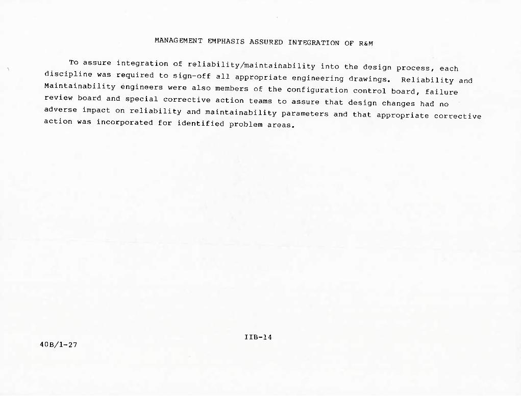
MANAGEMENT EMPHASIS ASSURED INTEGRATION OF R&M
TO assure integration of reliability/maintainability into the design process, each
discipline was required to sign-off all appropriate engineering drawings. Reliability and
Maintainability engineers were also members of the configuration control board, failure
review board and special corrective action teams to assure that design changes had no
adverse impact on reliability and maintainability parameters and that appropriate corrective action was incorporated for identified problem areas.
IIB-14 40B/1-27

MANAGEMENT EMPHASIS ASSURED INTEGRATION OF R&M
R&M DRAWING SIGN-OFF
R&M REPS ON CHANGE BOARD
FAILURE REVIEW BOARD
SPECIAL CORRECTIVE ACTION
EXECUTIVE MANAGEMENT
40A/5 IIB-15

PRIME SUB TEAM
During the course of this program confrontational negotiations were avoided. The
notion of team effort was strongly supported at all levels and actions were taken to
make this highly effective action work. For example, Westinghouse, in developing a set of
suppliers, undertook to provide assistance to small business to ensure that their products
were up to the quality level that was needed. To do this they provided motivational meetings
at which F-16 films were shown to the suppliers' employees, and award dinners were given when goals were met.
On a rare occasion a part supplier was unable or unwilling to make sufficient effort
to provide the quality part that was needed. In such cases, after working with the supplier to no avail, they were disqualified.
IIB-16

PRIME. SUB AND SUPPLIER WORKED AS A TEAM
• REQUIREMENTS TAILORED
- TWT -- HIGHLY RELIABLE. 3 TIMES BETTER THAN PREDICTED
BASED ON MIL HANDBOOK 217
• ASSISTANCE -- SMALL BUSINESSES
- MULTIPLIER -- LOW POWER RF LRU
• MOTIVATED SUPPLIERS
- SELECTIVELY
• INTERNAL DESIGN ACTIVITY FOCUSED TOWARD SUBCONTRACTOR
AND SUPPLIERS
- TWT ' ~' ^
- MULTIPLIERS
• IF ALL ELSE FAILS. SUPPLIER DISQUALIFIED
- PHP IIB-17
41/20

SPECIAL EMPHASIS FOR TWT
The TWT development program is an example of special emphasis management placed on system reliability.
During the competition it became evident that the TWT was a high-risk item and a
life-cycle cost driver. The Air Force and GD jointly devised a reliability test for the
TWT and included this test as a requirement in the RFP.
Westinghouse also imposed a reliability growth test on its subcontractors for TWTs.
As a result of these tests and the subsequent performance of the TWT in field use,
the next generation TWTs for the improved APG-66 has a similar reliability program specified,
IIB-18
40B/1-29
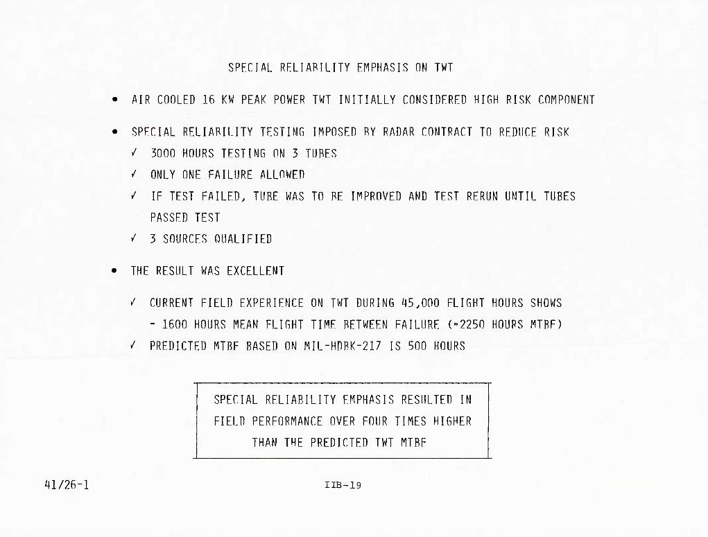
SPECIAL RELIABILITY EMPHASIS ON TWT
• AIR CnnLED 16 KW PEAK POWER TWT INITIALLY CONSIDERED HIGH RISK COMPONENT
• SPECIAL RELIABILITY TESTING IMPOSED BY RADAR CONTRACT TO REDUCE RISK
^ 3000 HOURS TESTING ON 3 TUBES
/ ONLY ONE FAILURE ALLOWED
/ IF TEST FAILED, TUBE WAS TO BE IMPROVED AND TEST RERUN UNTIL TUBES
PASSED TEST
V 3 SOURCES OUALIFIED
• THE RESULT WAS EXCELLENT
/ CURRENT FIELD EXPERIENCE ON TWT DURING 45.000 FLIGHT HOURS SHOWS
- 1600 HOURS MEAN FLIGHT TIME BETWEEN FAILURE (-2250 HOURS MTBF)
/ PREDICTED MTBF BASED ON MIL-HDBK-217 IS 500 HOURS - -
SPECIAL RELIABILITY EMPHASIS RESULTED IN
FIELD PERFORMANCE OVER FOUR TIMES HIGHER
THAN THE PREDICTED TWT MTBF
i|l/26-l IIB-19

DESIGN
IIC-l

DESIGN FACTORS
System design is the fundamental element in achieving a supportable system. Key
factors in the system design are listed on the facing page and described in subsequent charts.
IIC-2
40B/1-30
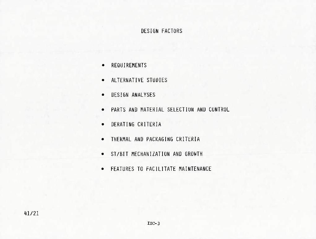
DESIGN FACTORS
REQUIREMENTS
ALTERNATIVE STUDIES
DESIGN ANALYSES
PARTS AND MATERIAL SELECTION AND CONTROL
DERATING CRITERIA
THERMAL AND PACKAGING CRITERIA
ST/BIT MECHANIZATION AND GROWTH
FEATURES TO FACILITATE MAINTENANCE
^1/21
IIC-3

DESIGN REQUIREMENTS
The APG-66 design requirement was developed cooperatively by both the Air Force and
General Dynamics considering experience on previous programs, the state of technology at
that time and the complexity involved. Requirements were determined to be compatible with
both mission and support needs and these were documented in the contractual statements
which were then given to GD and WEC.
Flexibility was considered a key parameter in the multi-level specification requirements
of a CFE development. The top specification which defines the weapon system performance
was supported by lower-level subsystem requirements. In the case of the APG-66 FCR, the
16ZE009 GD document contained a detailed level of performance requirements. The avionic
system specification necessary to effect weapon delivery accuracy is the next higher level
document. The flexibility existed wherein a difficult radar requirement could be analyzed
singly and in conjunction with avionics requirements. This flexibility made it possible to
modify the radar requirement and still not affect weapon delivery or to modify the avionics
mechanization without adversely affecting the radar. The system was designed from the top
down, thereby avoiding unrealistic subsystem requirements that have little or no weapon
delivery system effects.
Reliability Demonstration requirements were established and enforced using specific
accept/reject criteria. For example, the FSD RQT failed once and corrective action was
implemented before the test was restarted. As another example, the production reliability
qualification test and the reliability acceptance tests both failed twice before they were
successfully completed. In each case, a corrective action plan was submitted and approved
before a restart was allowed. This was in fact the case because the contract had firm
requirements vice goals. It should be noted that even for the successful tests, corrective
actions were taken and documented as part of the final report.
IIC-4 40B/1-31
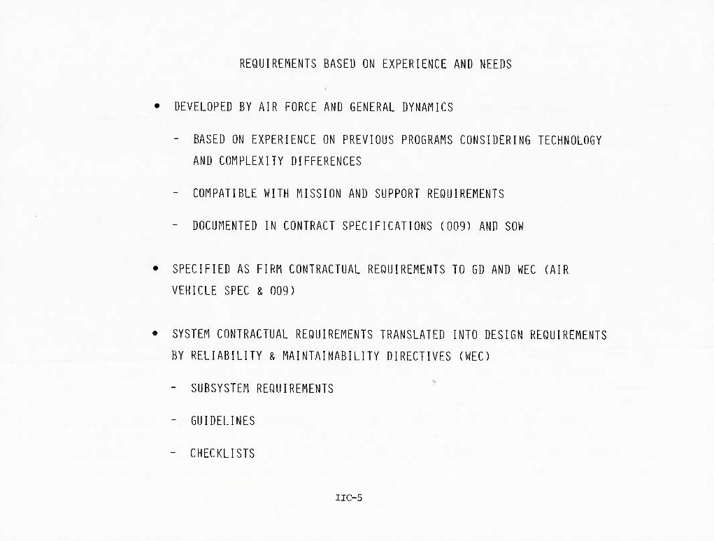
REQUIREMENTS BASED ON EXPERIENCE AND NEEDS
• DEVELOPED BY AIR FORCE AND GENERAL DYNAMICS
- BASED ON EXPERIENCE ON PREVIOUS PROGRAMS CONSIDERING TECHNOLOGY
AND COMPLEXITY DIFFERENCES
- COMPATIBLE WITH MISSION AND SUPPORT REQUIREMENTS
- DOCUMENTED IN CONTRACT SPECIFICATIONS (009) AND SOW
• SPECIFIED AS FIRM CONTRACTUAL REQUIREMENTS TO GD AND WEC (AIR
VEHICLE SPEC & 009)
• SYSTEM CONTRACTUAL REQUIREMENTS TRANSLATED INTO DESIGN REQUIREMENTS
.. BY RELIABILITY & MAINTAINABILITY DIRECTIVES (WEC)
- SUBSYSTEM REQUIREMENTS
- GUIDELINES
- CHECKLISTS
IIC-5
DESIGN ALTERNATIVE STUDIES
The design process for the APG-66 provided for design alternative studies. One set of
design alternative studies specifically set objectives for improved R&M. In many cases
decisions were made in favor of R&M over performance such as the use of copper heat sinks
in some applications on the DSP rather than aluminum. This action resulted in increased
weight and cost but increased reliability and subsequently improved life-cycle costs. In
addition, the use of wedgelocks on every board rather than alternate boards increased cost
and weight but was accepted because it enhanced maintainability. A second set, although
undertaken primarily for design-to-cost and weight reduction, provided many fallout benefits
to R&M. These benefits were achieved by including R&M in all design tradeoffs.
IIC-6 40B/1-32

^1/50
R&M IMPROVED BY DESIGN ALTERNATIVE STUDIES
DESIGN ALTERNATIVE STUDIES SPECIFICALLY FOR R&M ENHANCEMENT
• MANY DESIGN TRADE-OFFS MADE FOR R&M AT EXPENSE OF
WEIGHT AND COST
• DESIGN ALTERNATIVE STUDIES WITH R&M BENEFITS
• R&M AN INTEGRAL PART OF DESIGN TRADE-OFFS IN EARLY
DESIGN-TO-COST AND WEIGHT REDUCTION STUDIES
IIC-7

STUDIES TO ENHANCE R&M
The next two charts list seven design alternative studies whose purpose was to improve
the R&M of the APG-66 radar. Note that some of these studies involved an improvement to
the design of a previous system's component to scale it down for use in the APG-66.
Typically, in such an improvement the number of parts involved was reduced, thereby increas-
ing the potential MTBF. Sometimes, however, as in the case of relocating a heat exchanger,
the primary purpose was to obtain better cooling and therefore lower temperatures in the component involved.
IlC-f
40B/1-33

DESIGN ALTERNATIVE STUDIES AIMED AT ENHANCING R&M
DESCRIPTION PURPOSES
INVERTER DESIGN IMPROVEMENT FROM SCALED-DOWN AWACS DESIGN
A/D CONVERTER DESIGN IMPROVEMENT FROM SCALED-DOWN AWACS DESIGN TO NEW DESIGN
COMPARE LIQUID & AIR-COOLED TWT DESIGNS
UPGRADE QUALITY LEVEL OF 7 MEDs USED EXTENSIVELY IN SYSTEM
REDUCE PARTS COUNT
REDUCE WEIGHT
REDUCE PARTS COUNT
REDUCE WEIGHT
IMPROVE R&M
REDUCE WEIGHT
IMPROVE SYSTEM RELIABILITY
RELIABILITY IMPACT
PARTS COUNT REDUCED FROM 350 - 230
PARTS COUNT REDUCED FROM i\S2 - 112
MAINTAINABILITY IMPACT
ELIMINATES LIQUID COOLING SYSTEM COMPONENTS AND THEIR MAINTENANCE PROBLEMS (REDUCE RADAR WEIGHT 8-5 POUNDS)
APG-66 MTBF IMPROVED BY 4 TO 33%
IIC-9
41/^11-2

DESIGN ALTERNATIVE STUDIES AIMED AT ENHANCING R&M (CONTINUED)
DESCRIPTION PURPOSES
REPLACE HEAT EX- CHANGER ON BOTTOM OF POWER SUPPLY WITH VERTICAL EX- CHANGER FROM BACK TO FRONT THROUGH CENTER OF UNIT
• BETTER HEAT SINK ARRANGEMENT
• SIMPLIFY MANUF.
• REDUCE LCC
RELIABILITY IMPACT
REDUCE TEMPERATURES
MAINTAINABILITY IMPACT
SIGNIFICANT - EASIER "I" LEVEL ACCESSI- BILITY TO SRUs
COMPARE DISTRIBUTED POWER SUPPLY WITH CENTRAL POWER SUPPLY FOR ALL RADAR LRUs
DETERMINE IMPACT ON PARTS COUNT & MAINTAINABILITY
DISTRIBUTED POWER SUPPLY REDUCES PARTS COUNT BY >200
FAULT ISOLATION SIMPLIFIED BECAUSE LOAD VS. POWER SUPPLY DETERMINATION IS NOT REQUIRED SINCE BOTH ARE CONTAINED IN THE SAME SRU
STRUCTURE DSP CORNER TURN MEMORY FOR GROUND MAPPING MODES
SAVE WEIGHT. COST. COMPLEXITY
MTBF OF DSP INCREASED BY 15 HOURS BY ELIMINATING NEED FOR SEPARATE MEMORY
REDUCED REQUIRED NUMBER OF BIT TESTS TO VERIFY SATISFAC- TORY PERFORMANCE
IIC-ll
41/41-3

ALTERNATIVE STUDIES WITH R&M BENEFITS
The second set of design alternative studies shows five studies that were intended to
result in reduced costs or reduced weight and which, in addition, produced better R&M
characteristics.
IIC-12
40B/1-34

DESIGN ALTERNATIVE STUDIES WITH R&M BENEFITS
DESCRIPTION PURPOSES
SHOULD UNIPHASORS BE FURNISHED IN MATCHED SETS OF 4?
SHOULD PARAMETRIC AMPs BE REPLACED WITH FETs?
SHOULD THE SEPARATE VCO AND BEACON LO OPERATING IN SAME FREQUENCY RANGE BE COMBINED IN ONE PACKAGE?
SHOULD A ^K BIT RAM BE SUBSTITUTED FOR EXISTING IK BIT RAMS IN DSP CT & SC/ MEMORY BOARD
ASSESS BENEFITS OF SINGLE CHANNEL RECEIVE & PROCES- SOR
ELIMINATE COMPLEX MATCHING NETWORKS
REDUCE ACQUISITION COSTS
REDUCE RECURRING SYSTEM COSTS
REDUCE WEIGHT
REDUCE COST
REDUCE WEIGHT
REDUCE SRUs FROM ^ TO 2
REDUCE COST
REDUCE WEIGHT
REDUCE COSTS
REDUCE WEIGHT
RELIABILITY IMPACT
FAILURE RATE REDUCED 88%
FAILURE RATE REDUCED 66%
13% INCREASE IN LRU MTBF
FAILURE RATE REDUCED 16%
MAINTAINABILITY IMPACT
ELIMINATES HARMONIZA- TION REQUIREMENTS
SIGNIFICANT IMPROVE- MENT
REDUCE "I" LEVEL FAULT ISOLATION AMBIGUITY
FAILURE RATE REDUCED IMPROVED 18%
LRU MTBF INCREASED
INCREASED INHERENT MTBF BY 54 HOURS
lie-13
41/41-4

DESIGN ANALYSES
Proven reliability and maintainability design analyses were performed early in the
design phase and updated as the design progressed to:
• Assure achievement of reliability and maintainability requirements
• Maintain current estimates of radar reliability and maintainability characteristics
• Evaluate impact of changes on reliability and maintainability
• Provide reliability and maintainability inputs for use in design trades, life-cycle cost, and sparing analyses
A list of analyses performed is provided on the facing page.
IIC-14
40C/1-6

DESIGN ANALYSES
RELIABILITY MAINTAINABILITY
RELIABILITY PREDICTIONS
APPORTIONMENTS
THERMAL ANALYSIS
ELECTRICAL/MECHANICAL STRESS ANALYSIS
FAILURE MODES AND EFFECTS ANALYSIS
QUANTITATIVE MAINTAINABILITY ANALYSIS
MAINTAINABILITY PREDICTIONS
OPTIMUM REPAIR LEVEL ANALYSIS
ST/BIT EFFECTIVENESS ANALYSIS
TEST TOLERANCE ANALYSIS
lie-15
^1/51
PARTS PROGRAM TO IMPROVE RELIABILITY AND MAINTAINABILITY
Aggressive Parts Control and Standardization—Parts requirements imposed on all new
designs by specific requirements in the equipment specifications and by statements of work.
All subcontractor and in-house parts selections reviewed for military standard part. Full
government support provided to develop new military standards for multiple use parts.
Achieved State-of-the-Art Design and Commonality—The F-16 Parts Control Board main-
tained contact with Rome Air Development Center (RADC) for state-of-the-art device recom-
mendations. Commonality was achieved by selecting, based on RADC recommendations, the
preferred state-of-the-art device such as the microprocessor for all equipments to use.
Enhanced Manufacturing Producibility and Field Repairability—Enhanced manufacturing
producibility and field repairability by requiring maximum use of military standard parts
and standard packaging such as dual-in-line microcircuits.
Required Support Equipment and Trainers to Utilize Sames Parts as Aircraft—All new
and peculiar designs are required to select parts from the F-16 Program Parts Selection
List the same as the aircraft.
Program Adopted as Model for Future Programs—The F-16 program proved that Parts
Control and Standardization is cost effective for aircraft, support equipment and trainers.
The F-16 program also developed several innovative approaches such as a formal Part
Substitution Board and the use of DESC drawings. Military specifications are being revised
to incorporate F-16 techniques.
IIC-16
40C/1-7

PARTS PROGRAM TO I|viPROVE RELIABILITY ANP MAINTAINABILITY
• AGGRESSIVE PARTS CONTROL AND STANDARDIZATION
• ACHIEVED STATE-OF-THE-ART DESIGN AND COMMONALITY
• ENHANCED MANUFACTURING PRODUCIBILITY AND FIELD REPAIRABILITY
• REQUIRED SUPPORT EQUIPMENT AND TRAINERS TO UTILIZE SAME PARTS AS AIRCRAFT
• PROGRAM ADOPTED AS MODEL FOR FUTURE PROGRAMS
IIC-17 ^1/29-1

AGGRESSIVE PARTS CONTROL AND STANDARDIZATION PROGRAM
Use of high failure rate electromechanical parts was limited for all F-16 avionics.
For the radar this resulted in use of only six potentiometers, two relays and four motors.
Commonality was forced by reducing number of standards available to designers and
subcontractors. The F-16 Program Parts Selection List was established after a comprehensive
review of military specifications. The number of standards was reduced to only those with
established reliability requirements.
Several microcircuit technologies were eliminated from the parts selection list. The
F-16 Parts Control Board reviewed the microcircuit industry and established that the low
power shottky technology would be the leading technology for the 1980s. The 54H and 54L
technologies were eliminated from the PPSL. The dual-in-line microcircuit package was
selected over the flat pack.
Fastener types were reduced from 226 to 47 and the fastener recess standardized.
The military standards available for designers to select from were reduced to those
with established reliability requirements.
All variations from the selection list required detail justification such as the design
parameter necessitating the nonstandard. This justification was reviewed by the prime
contractor, the military review agency and finally by the F-16 Parts Control Board.
All part requests were reviewed for multiple usage. If two or more subcontractors ~ ^
used the same part, the review agency recommended that a military standard be developed for
the part.
IXC-18
40C/1-8
AGGRESSIVE PARTS CONTROL AND STANDARDIZATION PROGRAM
• USE OF HIGH FAILURE RATE ELECTROMECHANICAL PARTS LIMITED IN THE F-16
BY A VERY AGGRESSIVE STANDARDIZATION PROGRAM
• FORCED COMMONALITY BY REDUCING NUMBER OF STANDARDS AVAILABLE TO
DESIGNERS AND SUBCONTRACTORS
• ELIMINATED SEVERAL MICROCIRCUIT TECHNOLOGIES FROM SELECTION LIST
• REDUCED TYPES OF FASTENERS FROM SELECTION LIST
• LISTED ONLY ESTABLISHED RELIABILITY MILITARY STANDARDS
• JUSTIFICATION REQUIRED FOR ANY VARIATION FROM SELECTION LIST
• REVIEWED VARIATIONS FOR COMMON USAGE TO BECOME MILITARY STANDARDS
• WORKED WITH DEFENSE ELECTRONICS SUPPLY CENTER TO DEVELOP NEW DESC
DRAWINGS TO REPLACE MULTIPLE NONSTANDARD PART DRAWINGS
IIC-19
40/7

PARTS PROGRAM
A film describing the F-16 parts program was produced by DLA to describe the program
they believed to be a model. The film is available through DESC-EP.
IIC-20
40/1-52

MODEL PARTS PROGRAM
' FILM DOCUMENTATION
• DLA TO DOD
• AVAILABLE THROUGH
DESC-EP
IIG-21 41/39 .

DERATING
The General Dynamics reliability specification for subcontractors of F-16 major
electronic/electrical equipment, 16PP137 , required derating be implemented by Westinghouse.
Each piece part had to be derated consistent with its intended use, specified environment
and contribution to equipment unreliability. This information was used for a detailed
reliability prediction for the equipment at the piece part level using operating stress
and temperature environments. This piece part prediction was used to establish the predic-
tion for each higher level assembly and was kept current with design development. Derating
was reviewed at the PDR/CDR and reliability design reviews. Thermal derating was evaluated
during thermal verification tests.
IIC-22
40B/1-42
DERATING VITAL TO RELIABLE DESIGN
• GD CONTRACT REQUIRED WEC TO FORMULATE DERATING POLICY
• RADAR PROGRAM PLAN ESTABLISHED POLICY
• Q&RA DIRECTIVE IMPLEMENTED POLICY
• REVIEWED DURING PDR/CDR
• VERIFIED BY RELIABILITY DESIGN REVIEW AND STRESS
ANALYSIS AS DESIGN PROGRESSED
IlC-23
41/28-1
DERATING CRITERIA
A Westinghouse Q&RA directive dated 6 November 1975 establishes the Parts Derating
policy for the APG-66 radar. This policy states that the purpose of derating is to select
a part so that the manufacturer's rating of that part is well in excess of the stress values
that the part will actually experience in service in order to decrease part failure rate
The following tables present examples of the kinds of derating criteria that were used.
IIC-24
40B/16

APG-66 RADAR DERATING POLICY
EXAMPLES FROM Q&RA DIRECTIVE: R-3
MICROCIRCUITS
TRANSISTORS
DIODES
RESISTORS
COMPOSITION
WIRE WOUND. ACCURATE
WIRE WOUND. POWER
CAPACITORS
CERAMIC
TANTALUM. SOLID
60% RATED JUNCTION TEMPERATURE
60%
50% RATED POWER (FOR A GIVEN TEMPERATURE)
50%
20% " "
60% RATED VOLTAGE
60% ^ «
i|l/28-2
IIC-25

DERATING FOR COILS. CHOKES AND TRANSFORMERS
MAXIMUM PERMISSIBLE PERCENTAGE OF MANUFACTURER'S STRESS RATIO
COIL. INDUCTOR SATURABLE REACTOR
COIL-RADIO FREQUENCY FIXED
INDUCTOR GENERAL
TRANSFORMER. AUDIO
TRANSFORMER PULSE. LOW POWER '
TRANSFORMER. POWER
TRANSFORMER. RADIO FREQUENCY
TRANSFORMER. SATURABLE CORE
VOLTAGE CURRENT MAXIMUM TRANSIENT OPERATING
50% 90% 60%
60% 90% 70%
60% 90% 70%
60% 90% 70%
60% 70% 60%
60% 90% 70%
60% 90% 60%
60% 90% 60%
I (APPLIED) STRESS = I (ALLOWED)
PERCENT = (1-STRESS) x 100 DERATED
40/8 lie-27

THERMAL ANALYSIS AND VERIFICATION
Thermal analysis and verification was an important aspect of the APG-66 design. The
process is illustrated on the facing page.
The Air Force and GD established a practical limit of 140°F exit air temperature for
the F-16. Forced-air-cooled electronic equipment was provided cooling air from the environ-
mental control system to achieve the desired exit air temperature. This reduced exit air
temperature by approximately 20°F relative to earlier GD aircraft. To further enhance
reliability, the higher-powered components were placed nearest the edge or coolest part of
the SRU where possible and copper heat sinks were used in several locations rather than
aluminum since they conduct heat to the cooling plate much better than aluminum. After
these design features were incorporated, thermal verification tests were conducted to
assure that the analyses were valid.
Two test conditions were established for laboratory thermal verification. These conditions were:
- Radar at maximum heat dissipating mode
- Test conditions
TEST A TEST B
~ ^ Surrounding air 25° ± 2°C 55° ± 2°C
Cooling air
Temperature 2° ± 2° 40° ± 2°C
Flow rate 7 Ib/min 19 Ib/min
Corrective action was taken if any measurement varied more than ±5°C from predicted thermal analysis values.
A confirmation of key laboratory thermal values was obtained during flight tests.
IIC-28 40B/1-44

THERMAL ANALYSES AND VERIFICATION CRITICAL TO IMPROVED RELIABILITY
DEFINE THERMAL
ENVIRONMENT — >
THERMAL ANALYSIS ->
VERIFICATION
LABORATORY ->
VERIFICATION
FLIGHT TEST
t
f 1 1
1 1
DESIGN i 4-
<- , .-
4-
DESIGN f RESULTS __ _. - :: ^ - -
/ RELOCATION OF PARTS
/ RELOCATION OF CIRCUIT BOARDS
/ CHOICE OF HEAT SINK MATERIALS
/ APPORTIONMENT OF COOLING AIR BETWEEN LRUs
IlC-29
41/52

SELF TEST/BUILT-IN TEST
The F-16 avionic system incorporates a comprehensive fault detection and isolation
capability in support of the standard three level maintenance concept. During the mission,
continuous non-interruptive self testing is utilized to alert the pilot to malfunctions.
After the flight, maintenance personnel can utilize operator initiated built-in-tests (BIT)
for confidence checks and to supplement the self-test fault isolation. These two types of
test (self tests and BIT) provide both the capability to inform the pilot of any faults
that may require his attention or limit his mission and also provide maintenance personnel
with a detailed history and description of avionics failures.
40C/1-9 IIC-30

SELF-TEST/BUILT-IN TEST TERMINOLOGY AND MODES OF OPERATION
•
•
SELF-TEST IS A CONTINUOUS NONINTERRUPTIVE FAULT DETECTION FUNCTION
THAT IS MODE ORIENTED
- CPM: CONTINUOUS PERFORMANCE MONITOR
- NI: NONINTERRUPTIVE
- OFFBAR: TESTS CONDUCTED AT ANTENNA TURNAROUND
SELF-TEST IS USED TO DETERMINE HEALTH STATUS OF THE RADAR
- SELF-TEST REPORT TO FCC IS A SINGLE BIT REPORT ■
- SELF-TEST FAULT KEYED TO 80 DIFFERENT CHECKS
BUILT-IN TEST IS A HIERARCHICAL GROUP OF INTERRUPTIVE TESTS THAT
DETECT AND ISOLATE FAILURES TO A SINGLE LRU
- BITRADAR: AUTOMATICALLY INITIATED AT SYSTEM TURN-ON
- BITpcc: PILOT INITIATED VIA A/C FIRE CONTROL NAV PANEL
• PASS/FAIL FILTER PARAMETERS CAN BE DIFFERENT FOR SELF-TEST AND BIT
^1/53 iic-31
•

ST/BIT MECHANIZATION
The F-16 APG-66 radar system is packaged into six functional LRUs as indicated in the
facing block diagram. The ST/BIT Software program is an integral part of the Software
Operational Flight Program (OFF) that resides in the radar computer. All ST/BIT control
set-ups and monitoring is done via the system radar digibus/DSP bus—no special command
lines or monitor lines are required for ST/BIT. The ST/BIT fault reports and status are
transmitted to the A/C FCC for display to the operator via the Fire Control Navigation
Panel.
IIC-32
40C/1-10

F-16 SIMPLIFIED BLOCK DIAGRAM
(ST/BIT MECHANIZATION)
/SBSBSSSQll"^ Antenna |
p.s.
Uniphasor Driver
Servo
A
juarmnmnmMasw^ Transmitter
Pulser
LVPS
T^ _
1/0
A
DigiJiiia.
,imuiaiiinwaw«ftfffliHM LPRF
Controller 1
Slalo
Rec Video & I
1 A/D Conv i I ! I PS p
Mode I Freq.
Rarifle '"pTt
Anienna!
jgBBE^asBBBBaaam
A ^■"P"'^' ! do Inputs
fl/C P.S.JCPUI ,n,er ~ »^ —I—
"°|^n Inter
Synchro Inputs
DSP Bus L F-16 Avionics
Mux Bus Analog to SMS
(AIM-9L)
Triggers & Timlr^g
1 l-Q Bus
b^
SESSsyDBSBn
Processor
p.s.
Syncl)ronlzer
I ■ Scan "O I P'°« • Conv 1 1
RS-170 Video
IIC-33

F-16 ST/BIT READOUT
The Self-Test function of the F-16 Fire Control System is mechanized to serve a dual
purpose. Not only is the maintenance crew provided with all fault information, but the
pilot receives certain fault information which he may use to determine any degradation in
system performance. To accomplish these functions, two fault reporting schemes are used.
The Maintenance Fault List (MFL) contains the detailed information for all reported faults
while the pilot's fault list (PFL) contains the same information for only those faults that
would be of interest to the pilot. Thus, the PFL is merely a subset of the MFL. A degree
of severity is assigned to each fault which is easily interpreted by the pilot under flight conditions.
IIC-34 40C/1-11

F-16 ST/BIT READOUT
Degree of SeverifY
• Faulty Subsystem
• Test Number Failed
Call Up Maintenance Fault List
• Number of Occurrences (Up to 91
• Time into Flight of First Occurrence (Tenths of Minutel
• Fault Acknowledge Causes Sequence to Next Fault
77 0328V4
IlC-35

ST/BIT GROWTH AND DEVELOPMENT
ST/BIT design, development, integration and check-out was developed in parallel with
system design and mode development. The facing diagram shows the growth and development of
the ST/BIT as a function of time. This concurrent development approach provided the
opportunity to obtain early data on ST/BIT effectiveness and also provided additional test
capability to other engineering test programs such as RQT, RGT, EQT, and flight tests.
IIC-36 40C/1-12

% ST/BIT Complete
ST/BIT Growth
lie-37 81-0104-BB-e

PRE-DEMO FAULT INSERTION
In an effort to get an early evaluation of ST/BIT effectiveness, a fault insertion
program was instituted. The results of these incremental tests are included in the attached
figure. These test results are prior to any formal MIL-STD-471 demonstration and many test/
fix/retest occurrences resulted from this self-imposed WEC program.
IIC-38
40C/1-13

Pre-Demo Fault Insertion Status
No.ofSRUs Faulted
Faults Detected Faults Inserted
No. of Tests Exercised
Antenna 5 54/56 13
LPRF 11 80/120 30
TransnilUe|r 8 27/33 14
DSP 27 958/1090 19
Computer 13 86/103 17
RCP 3 43/60 6
Total 67 1 248 _ oro/ 1462"^^'^
99
lie-39

FEATURES TO FACILITATE MAINTENANCE
The Avionic Systems on the F-16, including the Radar, are designed around the standard
Air Force three-level maintenance concept: Organizational, Intermediate and Depot. At the
Organizational level (aircraft). Self Test and Built-in-Test are used as the primary tool
to checkout, detect and isolate malfunctions to a Line Replaceable Unit (LRU). The system
is functionally partitioned to facilitate isolating malfunctions to an LRU at the aircraft
level. At the Intermediate level (Avionics Intermediate Shop-AIS), sufficient test points
and access to internal circuits are designed into the system to allow position fault isola-
tion to a single Shop Replaceable Unit (SRU). The third level of maintenance like the AIS
uses automatic test equipment and special features designed into the circuits to provide
positive fault isolation to components on the SRUs. Additional features listed on the
facing page are designed into the hardware and software to accommodate the maintenance concept.
IIC-40 40C/1-14

FEATURES TO FACILITATE MAINTENANCE
•
DESIGNED FOR EASE OF MAINTENANCE
- LRU ACCESSIBILITY
- NO LRU BLIND CONNECTORS
- NO ADJUSTMENTS/CALIBRATIONS (ONLY 1 ADJUSTMENT AT I-LEVEL)
- NO PREVENTIVE MAINTENANCE
- DESIGN EMPHASIS TO PRECLUDE IMPROPER INSTALLATION
- LRU/SRU INSTALLATION HARDWARE IS CAPTIVE
- NO ON-AIRCRAFT BORESIGHTING
ST/BIT RESULTS DISPLAYED IN COCKPIT
- STORED IN NON-VOLATILE MEMORY
- RECALLABLE BY PILOT OR MAINTENANCE PERSONNEL
ill/35 iic-41

MAINTENANCE CONCEPT
This system was designed for ease of maintenance and compatibility with the standard three-level maintenance policy.
Organizational Level
Radar fault detection is provided by self-test features integral to the system design,
and reported to the pilot or maintenance personnel via cockpit displays. Self-test is a
continuous, non-interruptive process that requires no operator interaction. upon detection
of a fault, the operator may initiate built-in-test which provides fault isolation to the
failed line replaceable unit (LRU). This LRU is then removed from the aircraft, replaced
with a like serviceable unit, and system operation verified. The maintenance time require-
ments specified for these functions are: <0.5 hour mean corrective task time and 1.0 hour maximum corrective task time.
IIC-42
40B/1-45

ORGANIZATIONAL LEVEL MAINTENANCE CONCEPT
SELF TEST 95% DETECTION OF MALFUNCTIONS OR OUT-OF-TOLERANCE CONDITIONS
ST/BIT 95% ISOLATION TO FAULTY LRU
• REMOVE AND REPLACE FAULTY LRU
1N . FORWARD TO INTERMEDIATE ' LOW SKILL LEVEL REQUIRED-GENERALLY LEVEL THREE
SHOP FOR REPAIR _ _ -
2-9-83-g
lie-43
MAINTENANCE CONCEPT (Continued)
Intermediate Level
intermediate level maintenance consists of LRU checkout and fault isolation to a shop
replaceable unit (SRU). This is accomplished on the avionics intermediate shop test
equipment. LRU repair consists of removal and replacement of SRUs. Mean and maximum
corrective maintenance task times are specified at 1.0 hour and 2.0 hours, respectively.
IXC-44
40C/1-15

Intermediate Level Maintenance Concept
Repaired LRU Returned to Base Stores
• LRU Maintenance Time
- Mean (Met) <1.0 Hour
- Max (Mf^axct)<2.0 Hours
• Avionics Intermediate Test Station (AIS)
- "^(0% Isolation to Faulty SRU
- Remove and Replace Faulty SRU
- Verify Repair of LRU
• Within Skill Level Five Capability
♦ Faulty SRU Forwarded to Depot for Repair
B1-0104-BB-4

MAINTENANCE CONCEPT (Continued)
Depot Level
Depot level maintenance consists of SRU checkout and fault isolation to the failed
component(s), and includes all maintenance activity necessary to restore the unit to
serviceable condition. Additionally, any LRUs received from I-level due to NON-SRU failures
(i.e., chassis failures) are repaired at the depot.
IIC-46
40C/1-16

DFPnT LEVEL MAIMTFMAMCE CONCEPT
SRU FAULT ISOLATION REQUIREMENTS
- SINGLE ELEMENT >80%
- TWO ELEMENTS >85%
- THREE ELEMENTS >90%
DEPOT TEST STATION
- ISOLATION TO COMPONENT
- REMOVE AND REPLACE FAULTY
COMPONENT
- VERIFY REPAIR OF SRU
REPAIRED SRU RETURNED TO STORES
IIC-47
40A/21

MANUFACTURING
IIEHl
40A/29-4

MANUFACTURING
The fourth area identified as important to producing high quality military equipment
is in manufacturing or the actual production of the system. A number of techniques were
used by WEC in the production of the APG-66 radar. Key techniques are shown on the following page.
40B/1-46 IID-2

MANUFACTURING
•
EXTENSIVE USE OF ENVIRONMENTAi, STRESS SCREENING (ESS)
/ SUPPLIERS
/ INCOMING PIECE PARTS
/ PRINTED CIRCUIT BOARDS
/ SUB-ASSEMBLIES
/ LINE REPLACEABLE UNITS
SYSTEM LEVEL SAMPLE TEST
/ RQT ENVIRONMENTS
/ SELF IMPOSED BY WEC
PARTS SUBSTITUTION BOARD - --
/ PART OF PARTS CONTROL PROGRAM
/ ASSURE USE OF RELIABLE SUBSTITUTE PARTS WHEN
SUBSTITUTIONS ARE NECESSARY TO SUPPORT
PRODUCTION LINE
^1/43 IID-3

ENVIRONMENTAL STRESS SCREENING
Westinghouse followed a screening process they called "Environmental In-Line Testing."
This program was implemented throughout the production test cycle and was required of all
production systems with the objective of minimizing reliability defects and test escapes on delivered systems.
The program attempted to test at the lowest practical level to avoid rejection at
higher levels (which is always more expensive and time consuming). Environmental testing
is also accomplished at the LRU level for each deliverable LRU. The following environmental
tests were performed in-line: Vendor Assemblies, subjected to thermal cycling; Burn-in and
Selected Special Parameter Tests; and Active Components, from suppliers, undergo performance
tests over a range of temperatures including the extremes specified in MIL-STD-883.
Multiple Chip Hybrid Packages (MHPs) were tested environmentally per MIL-STD-883.
After initial acceptance, the MHPs were baked for 24 hours at 125°C, cycled through ten
repetitive exposures for ten minutes at -55°C, five minutes at room ambient and
ten minutes at 125°C followed by high g acceleration in a centrifuge for one minute. The
number of g's, from 5,000 to 15,000, varied with component size. Leak test and burn-in
followed to remove marginal performers. Burn-in was accomplished using normal dc voltages,
applied for 168 hours at 125°C, followed by the final electrical test at -54°C and +71°C,
in addition to the normal ambient test.
Printed Circuit Boards (PCBs) were tested as follows:
1. Active thermal cycling (-54°C and +71°C)
2. Subassemblies. Two subassemblies, the STALO and the receiver, were designated for
environmental testing with chamber temperature at -40°C and +71°C with
electrical tests occurring at the stabilized temperatures. After the temperature
test the PCB was exposed to random vibration. On completion of one failure-free
cycle, these subassemblies were installed in the LPRF LRU. 40B/1-47
IID-4

41/33-1
MANUFACTURING
• ENVIRONMENTAL STRESS SCREENING USED EXTENSIVELY
• ASSEMBLY VENDORS - THERMAL CYCLING; BURN-IN; GROSS/FINE LEAK;
OTHER SPECIAL SCREENS
• W INCOMING - MIL STD SEMICONDUCTOR AND ICs PERFORMANCE OVER
TEMPERATURE EXTREMES
• W MHPs - THERMAL SHOCK; THERMAL CYCLING; HI TEMP STORAGE;
ACCELERATED BURN-IN
• PRINTED CIRCUIT BOARDS - HI-LOW THERMAL CYCLING. PERFORMANCE
TEST
• SUB-ASSEMBLIES - HI-LOW THERMAL CYCLING; RANDOM VIBRATION
(COMBINED) ONE FAILURE FREE CYCLE
• LRUs - HI-LOW THERMAL CYCLING. RANDOM VIBRATION (COMBINED);
PERFORMANCE TESTS. ONE FAILURE FREE CYCLE
• FAILURE RESOLUTIONS—ESS FAILURE DATA PROVIDED BY TEST
ENGINEERING TO PROBLEM ACTION TEAMS FOR INVESTIGATION AND
TO PROBLEM ACTION BOARD FOR RESOLUTION
IID-5

All LRUS receive environmental tests as described above. In the event of a part
failure at the LRU level, the failure and associated corrective action was examined and if
it was determined that the integrity of the particular LRU performance had been affected,
the environmental testing was repeated. All burn-in data on deliverable LRUs was continuously evaluated to ensure reliability
control and to avoid increasing failure trends. Each LRU must demonstrate one failure-free
cycle prior to delivery (Test Level F). Failure data was provided to the problem action
teams for investigation and to the problem action board for correction.
IID-7
40B/1-

SYSTEM LEVEL SAMPLE TEST
Beginning in 1983, one radar system per month was selected to undergo combined
environmental testing including thermal cycling, random vibration and power on-off cycling in accordance with the RQT environmental profile.
The system level sample test was initiated by Westinghouse after completion of
Reliability Acceptance Test to assure that any new problems are identified and corrected
Benefits derived from RAT testing provided the motivation for incorporation of the system level sample tests.
IID-8
40C/1-17

SYSTEM LEVEL SAMPLE TEST
• SELF-IMPOSED BY WESTINGHOUSE STARTING JANUARY 1983
• SAMPLE: ONE RADAR PER MONTH
• ENVIRONMENT: SAME AS RQT
/ TEMPERATURE CYCLING
/ RANDOM VIBRATION
/ POWER ON-OFF CYCLING
• LENGTH OF TEST: 5 DAYS/SYSTEM
• OBJECTIVE: TIMELY IDENTIFICATION AND CORRECTION
OF ANY NEW PROBLEM AREAS
40A/29-3 IID-9

F-16 PARTS SUBSTITUTION BOARD
In 1977, the demand for parts exceeded the supply. Lead time for selected military
standard parts was running 26 weeks to 28 weeks. To ensure that production manufacturing
lines at the contractor and subcontractor were not shut down due to parts shortage, a
formal Part Substitution Board was authorized by the customer and established.
. The Air Force member of the board was selected from the local Air Force Program
Resident Office (AFPRO) and designated the Air Force agent.
• The Chairman of the Board was appointed from the Fort Worth Division Parts Advisory
Council to represent Fort Worth Division management.
• The technical advisor to the board was selected from the Fort Worth Division Parts
Engineering to serve as technical advisor on the acceptability of the part. The
Defense Electronic Supply Center was available for consultation as needed to assure
the best part available was used in the hardware.
• The material member of the board had access to the Fort Worth Division Material
Department to establish facts about the shortage, best available sources and the
implementation of the substitution authorization. The Material Board member was
^^^° ^^^ point of contact for subcontractors' request for substitutions.
Parts Engineering establishes best alternate part by coordination with part suppliers, DESC and Air Force.
The Part Substitution Board reviewed each substitution request for schedule impact.
The Part Substitution Board examines all part deviations. The board reviews these
deviations to ensure that the best part available is used.
IID-10 40B/1-51

F-16 PARTS SUBSTITUTION BOARD
• FORMAL BOARD ESTABLISHED TO REVIEW ALL PART SUBSTITUTIONS
(CONTRACTOR AND SUBCONTRACTOR)
• FOUR MEMBERS ON BOARD AT GD/FW
- AIR FORCE (LOCAL)
- CHAIRMAN (MEMBER OF PARTS ADVISORY COUNCIL)
- PARTS ENGINEER
- MATERIAL REPRESENTATIVE
• PARTS ENGINEERING ESTABLISHES BEST ALTERNATE PART OR PARTS
• BOARD APPROVES BEST PART THAT IS AVAILABLE FOR A LIMITED
QUANTITY BUY - - - - - '
• BOARD ALSO REVIEWS PART DEVIATIONS
IID-ll
i|l/i|6

MANUFACTURING YIELD AND FIELD RELIABILITY
The APG-66 Parts Control Board established the dual-in-line package as the preferred
package for manufacturing and field repairing. The flat pack was being phased out by many
microcircuit manufacturers. Also, the dual-in-line provided the best solution for multi-
layered printed circuit boards.
Studies of the APG-66 manufacturing lines revealed that microcircuits were exhibiting
higher than expected failures during the manufacturing cycle. A check of as-received stock
also confirmed the problem. Management elected to have all APG-66 microcircuits rescreened,
A dramatic reduction of microcircuit failures in manufacturing and field returns resulted.
Industry research revealed that electrostatic discharge was affecting manufacturing
and field reliability. The APG-66 Parts Control Board participated in the industry studies
and the subseguent DOD standards for electrostatic-sensitive devices (ESD). The APG-66
subcontractors were alerted to the problem and corrective action was taken to install ESD prevention systems.
IID-12 40B/1-41

MANUFACTURING YIELD AND FIELD RELIABILITY IMPROVED
•
ESTABLISHED DUAL IN-LINE MICROCIRCUITS AS STANDARD
ESTABLISHED MICROCIRCUIT RESCREEN TO IMPROVE MANUFACTURING YIELD
AND FIELD RELIABILITY
ESTABLISHED ELECTROSTATIC DAMAGE PREVENTION SYSTEM TO IMPROVE
MANUFACTURING YIELD AND FIELD RELIABILITY
IID-13
^1/29-4 .

TEST & EVALUATION
1
IIE-l

TEST EVALUATION SUMMARY
A SUMMARY OF THE FSD AND PRODUCTION ASSETS AND SCHEDULES FOLLOW
itOA/29-6
IIE-2

TEST & EVALUATION SUMMARY AP6-66 RADAR
41B/48
AS? :TS SCHE )ULE
PLANNED ACTUAL PLANNED ACTUAL
FSD
RGT 4 1 5-10/77 7-12/77
PRE-RQT 2 2
RQT 7-10/77
#1 3 2 3-4/78
#2 2 2 4-6/78
PROD-
RGT 0 1 7-11/78 7-11/78
RQT
#1 5 2 3-5/79
_ __ - #2 5 3 11/79- 2/80
#3 3 3 8-10/80
RAT
#1 4 4 11/80- 1/81
#2 2 2 7/81
#3 8 8 11/81- 10/82
IIE-3

The fifth area is Test and Evaluation. A great many different kinds of tests were
used to identify and correct problem areas and verify compliance with specified requirements.
These tests and evaluations are grouped into the following four categories and are described in more detail in the following pages.
IIE-4 4 OB/1-5 4

TEST AND EVALUATION
LABORATORY TEST (DEVELOPMENT)
DT&E FLIGHT TEST (DEVELOPMENT)
MOT&E (OPERATIONAL)
IN-SERVICE ASSESSMENT
i^l/32 , . IIE-5

LABORATORY TESTS
Laboratory testing played a vital role in the maturation of the APG-66 radar. The
ccmbined test activities have resulted in an MTBF, measured in the field, that is closer
to that measured in the laboratory than experienced on previous systems.
The extensive testing not only ferreted out failures but also provided a tool for
verifying the effectiveness of corrective actions. Reliability engineering was responsible
for the reliability testing while maintainability engineering monitored for effectiveness
of ST/BIT, and the hierarchy of tests, and added failure modes above those required in
maintainability demonstration tests. During the testing, a system acceptance test procedure
was run for each mode, and BIT was activated subsequent to each mode text.
Westinghouse management felt strongly that the tests were beneficial since, although
they had met their contractual commitments for formal testing demonstration, they committed
to continue testing one system per month under the reliability test environment to identify
any problems that result from the production process.
Extensive laboratory tests were conducted using FSD and production hardware. Tests conducted are shown.
IIE-6 40B/2-1
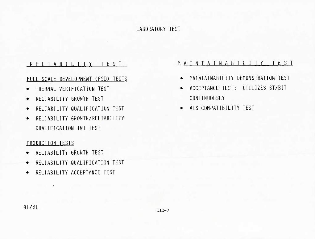
LABORATORY TEST
RELIABILITY TEST
FULL SCALE DEVELOPMENT (FSD) TESTS
• THERMAL VERIFICATION TEST
• RELIABILITY GROWTH TEST
• RELIABILITY QUALIFICATION TEST
• RELIABILITY GROWTH/RELIABILITY
QUALIFICATION TWT TEST
MAINTAINABILITY TEST
• MAINTAINABILITY DEMONSTRATION TEST
• ACCEPTANCE TEST: UTILIZES ST/BIT
CONTINUOUSLY
• AIS COMPATIBILITY TEST
PRODUCTION TESTS
• RELIABILITY GROWTH TEST
• RELIABILITY QUALIFICATION TEST
• RELIABILITY ACCEPTANCE TEST
41/31 HE-7

LABORATORY RELIABILITY TESTING
Reliability testing was performed during development and production in the laboratory
under combined environments including random vibration, rapid temperature excursions and
power on-off cycling with limited use of humidity and altitude environments. The purpose
of the testing was early detection and correction of problem areas and demonstration of
compliance with specified MTBF.
Types of testing included reliability growth and reliability qualification during full-
scale development and reliability growth, reliability qualification and reliability acceptance
testing during production.
Reliability growth testing was performed at the system and equipment level and at the
component level for critical components such as the TWT. An example of the effectiveness
of growth testing is the 23 corrective actions identified during 420 hours of development
growth testing.
Reliability, qualification and acceptance testing was performed at the radar system
level in compliance with MIL-STD-781 test plans. In each case incorporation of extensive
corrective action followed by retests were necessary prior to successful completion.
Corrective action was incorporated for all identified problem areas.
IIE-8
40B/2-2

APG-66 RADAR IABORATORY RELIABILITY TESTING
PROGRAM APPROACH
m/i\2
PERFORM RELIABILITY GROWTH TESTING FOR EARLY DETECTION AND CORRECTION OF PROBLEM AREAS — COMBINED ENVIRONMENTS
- TEMPERATURE CYCLING - ALTITUDE CYCLING - HUMIDITY - POWER ON-OFF CYCLING
- RANDOM VIBRATION
PERFORM EXTENDED TIME REL-QUAL TESTS UNDER TEMPERATURE AND RANDOM VIBRATION ENVIRONMENT FOR EARLY DETECTION/CORRECTION OF PROBLEM AREAS AND DEMONSTRATION OF COMPLIANCE WITH SPECIFIED MTBF
PERFORM EXTENDED-TIME REL-ACCEPTANCE TEST UNDER TEMPERATURE AND RANDOM VIBRATION ENVIRONMENT TO VERIFY RELIABILITY CONTROL
TEST SUMMARY
PHASE TYPE TEST
MI.-S ■D-781B " SPECIFIED MTBF (On)
SYSTEM QUANTITY
TOIAL TEST HOURS
NUMBER OF CORRECTIVE ACTIONS PLAN LEVEL
FSD GROWTH - 1 420 23
FSD PRE-RQT - F* - 2 470 19
FSD RQT Ill F* 50 2 730 22
PROD. GROWTH - - 1 230 6
PROD. RQT III/IV F* 97 3 720 56
PROD. RAT V F* 97 8 420 48
*TEST LEVEL F EXCEPT LOWER TEMPERATURE LIMIT OF -40°C AND RANDOM VIBRATION IN LIEU OF SINUSOIDAL.
IIE-9

TEMPERATURE AND RANDOM VIBRATION PROFILES
Pictorial representation of temperature and random vibration for RQT and RAT is
shown. For the temperature cycling, the following conditions apply:
• During the cooling portion of each cycle the chamber was stabilized at -54°C.
When the point of maximum thermal inertia (as determined by thermal survey) of the
equipment under test reached -40°C, the chamber was then stabilized and maintained at that temperature for 45 minutes.
• Equipment power, cooling air, and chamber heating were then applied to initiate the heating portion of the cycle.
• Test time following stabilization at high temperature was one hour and 45 minutes.
• Any cooling air to enhance transition to cold temperature was applied at a
temperature no greater than the existing chamber ambient temperature. Any cooling
air applied to enhance transition from -54°C to -40°C was applied at -40°C.
Cooling air at +27°C was applied at the beginning of the heating portion of each
cycle and was maintained throughout the high temperature portion of the cycle.
• All references to "test time," "test duration," and "equipment operation" are
understood to mean equipment "on-time" for the purpose of calculating MTBF.
— Random vibration was performed during the tests. The duration and test levels were
maintained within ±10% of the values identified in the figure. Vibration was applied
normal to the plane for the majority of the circuit boards contained in the equipment.
The equipment was turned on and operated at -40°C at the start of the high temperature
cycle. After stabilization at high temperature, the equipment was operated at least 1-3/4
hours. The total system operation time was five hours, five minutes for each temperature
cycle. During equipment test time the equipment was cycled through its various modes of operation.
IIE-10 40B/2-4

RQT AND RAT WERE ACCOMPLISHED USING
COMBINED ENVIRONMENTS OF TEMPERATURE AND RANDOM VIBRATION
TEMPERATURE
V TlwiiHl lanmr - t-Xt N«l IHt
IHrlMhl- 2Hf WMin
JHrHMIa
^ammammm Svtnm Tamil
T, SiMMMiMMn tram loom lo -4a°C
Tj SialMlifMMMi (ram -W°C lo ''I'c
' Vikraa lor 14 Mhi Ovi ol fad* OairMmt Hour par Nqr Pvoaduf*
■IlE-11 -J
RANDOM VIBRATION fcawitrt*«i»i*—> >
ao 70' SQO 1000 Fraquancy (Hz)
2000
TtitLtvtl 1
T«Tim«* W, (r'Hz) WQ 0/t^ rm»
8min 0.0003 0.0014 1.32G
A mni 0.00042 0.0030 1.94G
2niin aooio 0.0070 2.96G
*Expr«Md M Uin Out of Each Oparadng Hour

RANDOM VIBRATION TEST REPRESENTATIVE OF ACTUAL FLIGHT CONDITIONS
Extensive random vibration was used. The vibration test levels specified in 16PS002
were to be used unless actual data became available. The charts depict both the specified
level from 16PS002 and the current requirement based on measured aircraft vibration levels.
40B/17 ,,,,:_ . ,, I^E-12

CURRENT RANDOM VIBRATION SPECTRUM IS REPRESENTATIVE
-| ORIGINAL"^
• 16PS002 STATES - "F-16" DERIVED VIBRATION LEVELS WILL BE USED IF LESS SEVERE THAN THIS SPECTRUM"
■\ CURRENT"^
• DATA PLOTS ARE PEAK G2/HI POINTS FROM FLIGHT TEST DATA
FWD AVIONIC BAY - BASIC STRUCTURE ATTACH
G^/Hi
HE-13
.0001
BI3B37

RELIABILITY GROWTH PREDICTION
Westinghouse instituted a reliability growth "test-and-fix" effort as an integral part
of the overall growth program. It was planned that this effort would mature the APG-66
production radar to a demonstrable 100 hours MTBF. The test involved cycling a sample in a
simulated use environment to accelerate the occurrence of failures and then to identify,
analyze, and correct the causes of such failures in a closed-loop cycle. The figure
following shows the intended reliability growth as a function of the program milestones.
The starting point is assumed to be 10% of the predicted inherent MTBF (163 hours for the
FSD system). The first inflection point of this curve represents the level of growth
expected to occur during the early part of FSD as a result of environmental testing and
screening at and below the LRU level. The second inflection point on this chart represents
the level of MTBF expected to be achieved by learning from the combination of environmental
qualification tests and the dedicated reliability growth test.
IIE-14
40B/18-2 -

RELIABILITY GROWTH PREDICTION
247
163
100
_ PBOpU£TiqN BASELINE PREDICTION
FSO BASELINE PREDICTION
PRODUCTION QUAL TEST REQUIREMENT
DC 3 o X
60 FSD DUAL TEST REQUIREMENT
PRODUCTION BASELINE GROWTH
100
[
1500 2000 10000
TEST AND FIX (SYSTEM HOURS) 75-0723-VB-17.J
HE-15
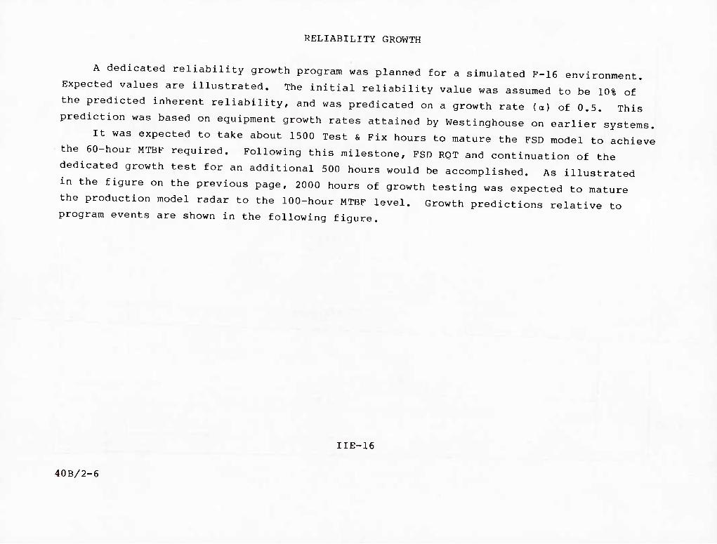
RELIABILITY GROWTH
A dedicated reliability growth program was planned for a simulated F-16 environment.
Expected values are illustrated. The initial reliability value was assumed to be 10% of'
the predicted inherent reliability, and was predicated on a growth rate (a) of 0.5. This
prediction was based on equipment growth rates attained by Westinghouse on earlier systems.
It was expected to take about 1500 Test & Fix hours to mature the FSD model to achieve
the 60-hour MTBF required. Following this milestone, FSD RQT and continuation of the
dedicated growth test for an additional 500 hours would be accomplished. As illustrated '
in the figure on the previous page, 2000 hours of growth testing was expected to mature
the production model radar to the 100-hour MTBF level. Growth predictions relative to program events are shown in the following figure.
IIE-16
40B/2-6

APG-66 RELIABILITY GROWTH HRtUICTIUNS
IM
)l
Hiir
?»
w tin III! III!
100 HR
J INTROOUCIIOHOniORE
^OUAMflEOrARTt
- 'V^ mm
MHR l£
II HI ""■ — 11H /
-- - "' ' -
aEtiCN courif TiOH
fNC. imaMioav (vtiNTfe ,„. UNtE
■EICROWTH 4 fiST , UHR 1
1^ RQI 100 .[Hvmouil.. (to ROT .1 HRrROQl
cvi.Tm.T r Go/rwrii J n r"
lESI
»OIIIV}M
IlE-n
FSD RELIABILITY GROWTH TEST (RGT)
One system (#6) was used for RGT. The system was tested a total of 420 hours and 23
corrective actions were subsequently taken as a result. Examples of resultant changes are shown.
40A/24-4 IIE-18
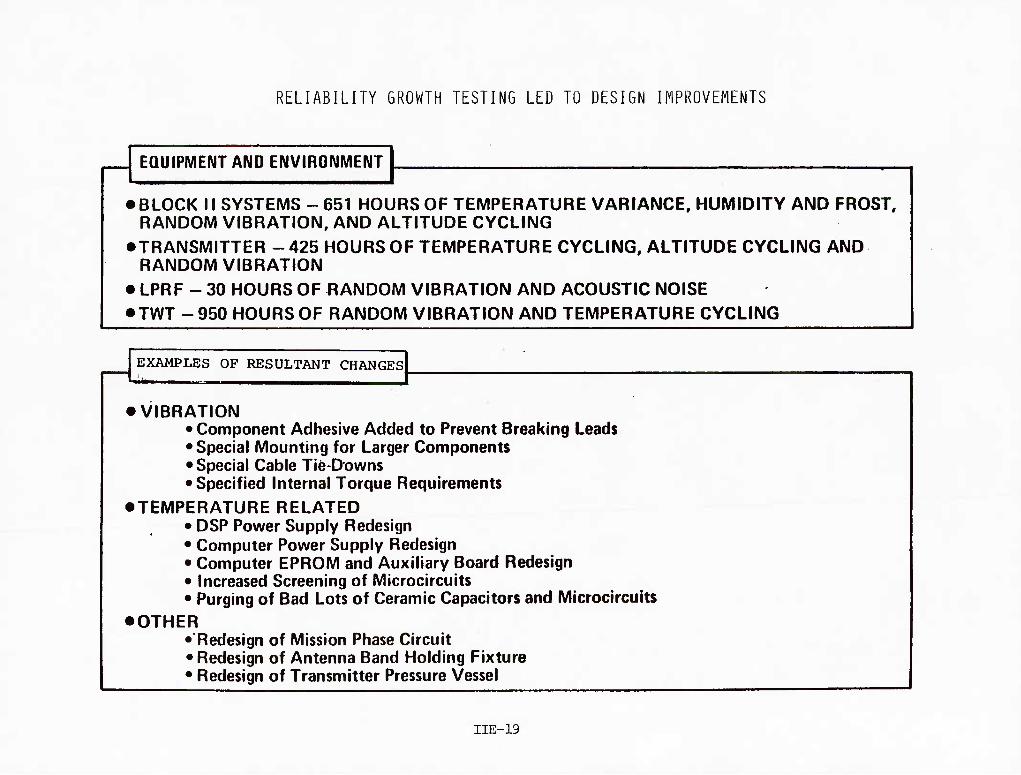
RELIABILITY GROWTH TESTING LED TO DESIGN IMPROVEMENTS
EQUIPMENT AND ENVIRONMENT
• BLOCK 11 SYSTEMS - 651 HOURS OF TEMPERATURE VARIANCE, HUMIDITY AND FROST. RANDOM VIBRATION. AND ALTITUDE CYCLING
• TRANSMITTER - 425 HOURS OF TEMPERATURE CYCLING, ALTITUDE CYCLING AND RANDOM VIBRATION
• LPRF - 30 HOURS OF RANDOM VIBRATION AND ACOUSTIC NOISE • TWT - 950 HOURS OF RANDOM VIBRATION AND TEMPERATURE CYCLING
EXAMPLES OF RESULTANT CHANGES
• VIBRATION • Component Adhesive Added to Prevent Breaking Leads •Special Mounting for Larger Components • Special Cable Tie-Downs • Specified Internal Torque Requirements
• TEMPERATURE RELATED • DSP Power Supply Redesign • Computer Power Supply Redesign • Computer EPROM and Auxiliary Board Redesign • Increased Screening of Microcircuits • Purging of Bad Lots of Ceramic Capacitors and Microcircuits
•OTHER •Redesign of Mission Phase Circuit • Redesign of Antenna Band Holding Fixture • Redesign of Transmitter Pressure Vessel
HE-19

FSD RELIABILITY GROWTH (Continued)
Typical test cycles used during RGT are shown,
IIE-20

KHM I—I'r «aaaFT W.TITUDE
Si 0
2 -O
W 13 TWE mous
1 x 20 S
•40
•n
0
•39
Reliability GxuwtL T-A-H Test Cycle - 2 Cydea Prior to and after Testing and after £ae2i 200 Hours of Operation
44J«C
FLOW RATES AS OESmtBEO IN S?EC
STSOFF »■■ SYS ON
J. J_ _L _L U 12 U
TIME-HOURS IS II a s 2«
75.B723-VA-7U1
IIE-21 System Cooling Air Cycle for Reliability GxtiwOi T*A>H Test Cycle

FSD PRE-ROT TESTING
Prior to the initiation of Reliability Qualification Testing, Westinghouse performed
environmental integration testing to identify and resolve problems. This pre-RQT testing
was expected to improve the probability of passing the RQT. Two systems were tested (SYS 9
& 10) for a total of 470 hours. Nineteen corrective actions were subsequently incorporated,
Failure types and corrective action taken are shown on subsequent charts.
IIE-22 40A/24-5 , ;
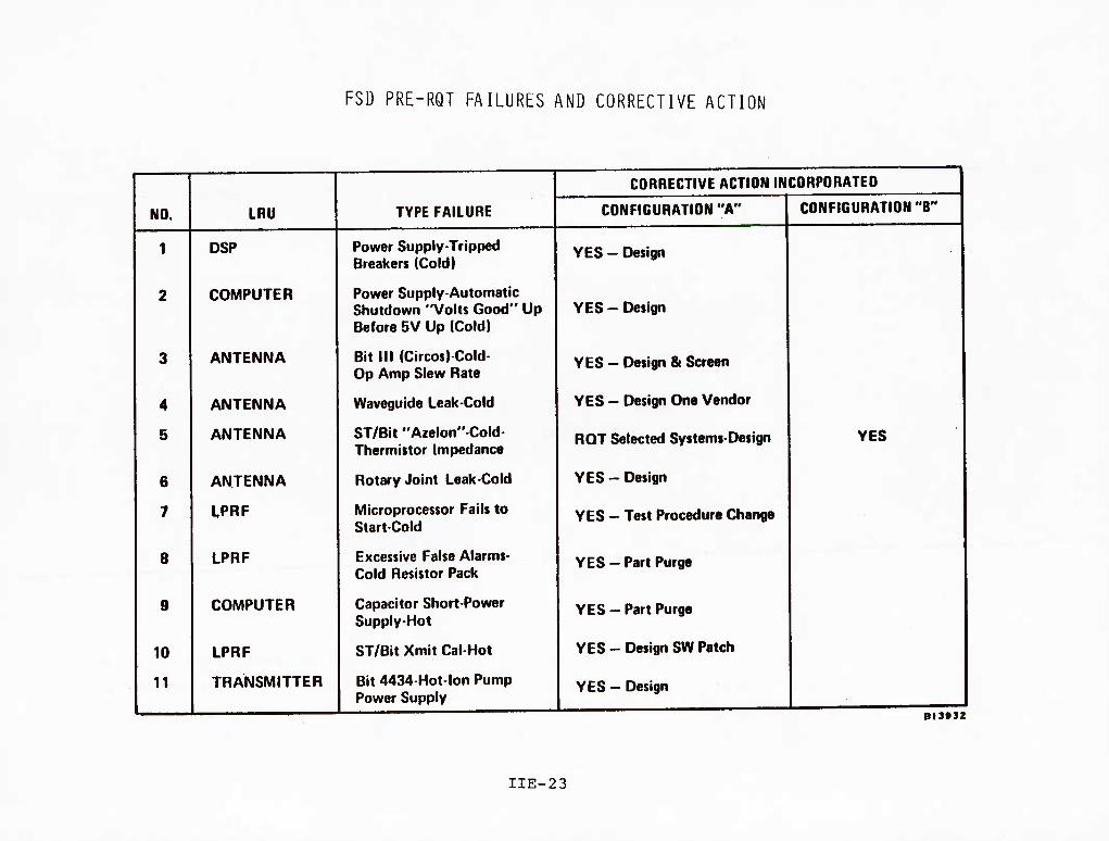
FSD PRE-RQT FAILURES AND CORRECTIVE ACTION
NO. LRU
1 DSP
2 COMPUTER
3 ANTENNA
4 ANTENNA
5 ANTENNA
6 ANTENNA
7 LPRF
8 LPRF
9 COMPUTER
10 LPRF
11 TRANSMITTER
TYPE FAILURE
Power Supply-Tripped Breakers (Cold)
Power Supply-Automatic Shutdown "Volts Good" Up Before 5V Up (Cold)
Bit III (Circos)-Cold- Op Amp Slew Rate
Waveguide Leak-Cold
ST/Bit "Azelon"-Cold- Thermistor Impedance
Rotary Joint Leak-Cold
Microprocessor Fails to Start-Cold
Excessive False Alarms- Cold Resistor Pack
Capacitor Short-Power Supply-Hot
ST/Bit Xmit Cal-Hot
Bit 4434-Hot-lon Pump I Power Supply
CORRECTIVE ACTION INCORPORATED
CONFIGURATION "A'
YES - Design
YES - Design
YES - Design & Screen
YES - Design One Vendor
ROT Selected Systems-Design
YES - Design
YES - Test Procedure Change
YES - Part Purge
YES - Part Purge
YES-DesignSWPatch
YES - Design
CONFIGURATION "B'
YES
BI3932
IIE-23

FST PRE-RQT SYSTEMS 9 AND 10 FAILURES
AND CORRECTIVE ACTION (CONTINUED)
NO. LRU TYPE FAILURE
CORRECTIVE ACTION INCORPORATED
CONFIGURATION "A" CONFIGURATION "B"
12
13
14
15
16
17
18
19
LPRF
COMPUTER
ANTENNA
ANTENNA
DSP
ANTENNA
TRANSMITTER
ANTENNA
False Alarms-Hot-Resistor Pack
R2 Broken Loose-Vibration
Boresight Shift-Vibration
Drive Band Broke-Vibration
ST/Bit "Ext Wat"Vibration Power Supply
Broken Lead Digibus MHP- Vibration
Pressure Vessel Leak at Cover
Flex Cable Damage
YES - Part Purge See 8
YES - Application Proced
YES - Design
YES - Design
YES - Adjust Procedure
YES - Assembly Spec
YES - New Test Equip
YES - Design
.
dl9»S3
IIE-25

FSD RELIABILITY QUALIFICATION TEST
At the completion of FSD growth testing, Westinghouse was required to demonstrate
full compliance with the specified APG-66 radar reliability requirement of 60 hours MTBF
(70 hours excluding ground modes). The test was conducted in accordance with MIL-STD-781B,
Test Level F as modified by the contract. Three radar systems were required to be tested.
The test duration depended on the number of failures, and the environmental schedule includ-
ing vibration as contractually specified was to be followed. The results of the RQT are shown in the following table.
APG-66 RADAR RELIABILITY QUALIFICATION TEST (RQT)
Test Relevant
Test Type Attempt No. Hours Failures Corrective Actions*
ROT 1 33 3 (failed) 3
2 721 13 (passed) _23
26
'Corrective actions were taken for failures that occurred during set-
up for RQT, RQT and troubleshooting periods.
Relevant failures and subsequent corrective actions are itemized on subsequent charts,
40B/2-9 "■'' ■ '" ■'
IIE-26

(/>
a Ui en
a »-
APG-66 RADAR FSD RELIABILITY QUALIFICATION TEST PASS/FAIL CRITERIA
18
16
14
12
10
8
6
4
2
SPECIFIED HTBFfe ) o TEST PLAN III
60HRS
!
REJECT 1
PASSED «; F r n N n
•
^
-1 ATTEMPT
/ y
/
\ y^ CONTINUE TEST
• y
\y *'
• J ̂ /
>
— FAILED FIRST ATTEMPl y ̂ ^\
1 /
ACCEPT
' / A Y' __ .'
// - — r / y^ 1 1
• DESIGN COf ERECTIONS n /^
\ ^^
^
100 200 300 400 500 600 700 800
TOTAL TEST TIME IN HOURS
IIE-27

INITIAL FSD RQT
FAILURES AND CORRECTIVE ACTIONS
NO. LRU TYPE FAILURE
CORRECTIVE ACTION INCORPORATED
CONFIGURATION "A"
CORRECTIVE ACTION INCORPORATED
CONFIGURATION "B"
1 LPRF Bit PLOKFL - Vibration YES - Design
2 COMPUTER Broken Lead Power Supply Vibration
YES - Design
3 DSP False Alarms YES - Design
BIStSS
IIE-29

RQT FOR THE TWT
During the competition for a radar supplier it became evident that the TWT was a high-
risk item and likely to be a cost driver. The Air Force and GD jointly devised a reliability
test for the TWT and included this test as a requirement in the RFP. Westinghouse, as the
successful contractor, then further imposed a reliability growth test on their subcontractors
for TWTs. Up to this time no production air-cooled TWT had ever been flown. But for
reasons of weight and simplicity, WEC decided that an air-cooled TWT would be desirable for
the F-16 application. Their specification for potential suppliers included the need for a
reliability growth program. As a result of the subsequent performance of the TWT in field
use, the next generation of TWT on the improved APG-66 also has a similar reliability
program specified. The resulting design currently has demonstrated four times the MTBF
that had originally been predicted and three suppliers have been qualified to provide such
a TWT. The high reliability is even more impressive when one considers that the failures
of a number of TWTs were maintenance-induced, i.e., waveguides were not connected properly
and the subsequent loss of pressurization caused repeated arcing that cracked the TWT window. ,. — _
IIE-30
40B/2-8
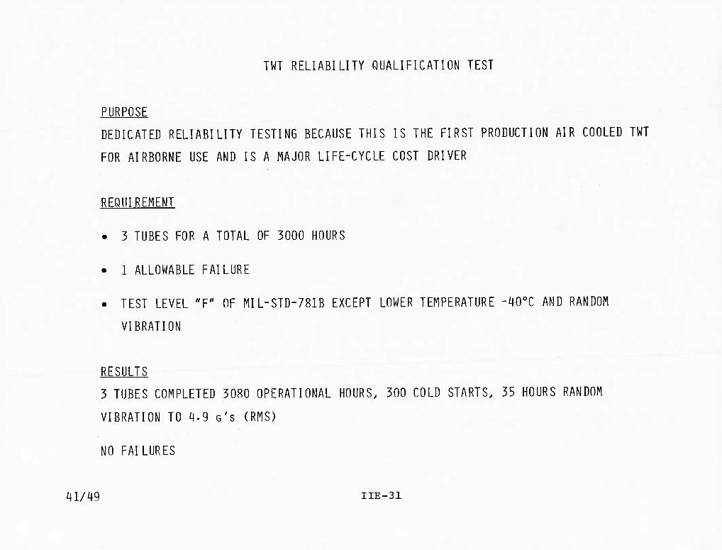
TWT RELIABILITY QUALIFICATION TEST
PURPOSE
DEDICATED RELIABILITY TESTING BECAUSE THIS IS THE FIRST PRODUCTION AIR COOLED TWT
FOR AIRBORNE USE AND IS A MAJOR LIFE-CYCLE COST DRIVER
REQUIREMENT
• 3 TUBES FOR A TOTAL OF 3000 HOURS
• 1 ALLOWABLE FAILURE
• TEST LEVEL "F" OF MIL-STD-781B EXCEPT LOWER TEMPERATURE -40°C AND RANDOM
VIBRATION
RESULTS ^
3 TUBES COMPLETED 3080 OPERATIONAL HOURS. 300 COLD STARTS. 35 HOURS RANDOM
VIBRATION TO 4-9 G'S (RMS)
NO FAILURES
41/49 IIE-31

PRODUCTION RELIABILITY GROWTH TEST
One production system (#20) was used to accomplish production reliability growth
testing. Production growth testing was implemented to further mature radar reliability
after development RQT and prior to production RQT. Environments included temperature
cycling, power on-off cycling and random vibration. RQT performance measurement procedures
were used. However, temperature and vibration profiles were used to increase stress levels and radar power-on time efficiency.
IIE-32 40B/2-28

PRODUCTION RELIABILITY TEST
EQUIPMENT & ENVIRONMENT
• ONE SYSTEM - PRODUCTION SYSTEM #20
• 230 TEST HOURS
• TEMPERATURE CYCLING 1^ PROFILE A EMPHASIZED TURN-ON STRESS AT COLD TEMPERATURE (-40°C) -^ PROFILE B EMPHASIZED HIGH TEMPERATURE STRESS (+71°C)
• RANDOM VIBRATION - 14 MINUTES/OPERATE HOUR FROM 20 TO 2000 HZ "I 8 MINUTES AT IGRMS ^ 4 MINUTES AT 2-6GRMS ^ 2 MINUTES AT 4-6GRMS
EXAMPLES OF RESULTANT CHANGES
• VIBRATION ^ DEDICATED GROUND WIRE ADDED ^ ASSEMBLY AND INSPECTION IMPROVEMENTS INCORPORATED
• TEMPERATURE ^ ^ CAPACITANCE INCREASED ON POWER TRANSFORMER
• OTHER "I DIGITAL SIGNAL PROCESSOR TESTS ADDED ^ PROCESS AND DESIGN CHARGES INCORPORATED TO CORRECT
TRANSMITTER HIGH VOLTAGE DIODE BLOCK PROBLEM
40B/2-26
IIE-33

PRODUCTION RQT
Westinghouse was required to demonstrate full compliance with the specified requirement
of 100 hours MTBF (125 hours excluding ground mapping modes). This production RQT was to
be conducted in accordance with the test plan used for FSD, and was performed on 5 of the
first 25 deliverable production radars. Compliance with MIL-STD-781B was demonstrated
when Test Plan III accept criteria for number of failures versus operating times were met.
The results of the Production RQT are also shown in the following table.
Test Total Relevant
Attempt No. Hours Hours Failures
Corrective
Actions
Prod ROT 1 2
3
80 192 4 (failed)
229 364 6 (failed)
271 400 2 (passed)
21
24
10
55
Sixty-five corrective actions were made for failures that occurred during RQT as well as
for problems identified while troubleshooting.
IIE-34 40B/2-10

RADAR PRODUCTION ROT PASS/FAILURE CRITERIA SPECIFIED MTBF (eo) = 97 HOURS
TEST PLAN IV*
8
7
CO UJ oc =3
u. o UJ
£ 2
0
RQT#1
\
^ -r I I
■
I ■
J 100
RQT#2
h ;JECT
^^
.•• • I
y
I
e ,.'••
CONTINUE TEST
I
^X
.^
ACCEPT
RQT#3
200 300 TOTAL TEST TIME IN HOURS
2-9-83-7 *RQT #1 and #2 were conducted using Test Plan III.
400
..'"
500
HE-35

PRODUCTION RELIABILITY ACCEPTANCE TESTS
Reliability acceptance testing (RAT) began on November 17, 1980 and was completed on
September 30, 1982. Two attempts resulted in reject decisions. Testing was conducted in
accordance with MIL-STD 781B, Test Plan V, Level F, amended to include random vibration and
a lower test temperature of -40°C. RAT 3 demonstrated that the radar meets the specified MTBF (9o) of 97 hours.
HE-36
40A/22-1

APG-56 PRODUCTION RELIABILITY ACCEPTANCE TESTS
TOTAL NUMBER OF FAILURES
I I ' ' I ' ' I ' I ' ' ' ' I ' ' ' I ' ' ' I
RAT 2
-RAT 3
I I I I I I I I I
100 200 300 400
TOTALTESTTIME (HOURS)
500
HE-37

RELIABILITY ACCEPTANCE TEST
The first Reliability Acceptance Test was initiated on November 17, 1980 and was
stopped on January 28, 1981. Four systems were used for the test.
A test reject condition was reached when the fifth test failure occurred at the 75-
hour test point. During the 161 hours of reference testing and troubleshooting (non-test
hours), 18 additional failures were identified. All failures were evaluated for cause and
possible corrective action. For the total of 23 failures, the causes of failure were iden-
tified for 14 failures, while 9 were for unknown causes. Twelve corrective actions were
taken to correct the 14 failures for which the causes of failure were known.
The second RAT attempt began on July 2, 1981 and was stopped on July 18, 1981. Two sys-
tems were tested. A test reject condition was reached when the second test failure occurred
at the twelve-hour test point. During the 49 hours of reference testing and troubleshooting
(non-test hours), nine additional failures were identified. All failures were analyzed for
cause and possible corrective action. For the total of 11 failures, the causes of failure
were identified for 10 failures while one was for unknown causes. Nine corrective actions
were taken to correct the 10 failures for which the causes of failure was known.
The third attempt of the RAT was started on November 20, 1981 and was successfully com-
pleted on 30 September 1982. During this period, 335 test hours were accumulated with five
relevant failures. This test demonstrated that the radar meets the specified MTBF (BQ)
of 97 hours. Eight systems were used for the test. During the 85 hours of reference test-
ing and troubleshooting (non-test hours) 25 additional failures were identified.
All failures were analyzed for cause and possible corrective action. For the total of
30 failures, the causes of failure were identified for 26 failures while 4 were for unknown
causes. Twenty-six corrective actions were taken to correct the 26 failures for which the
causes of failure were known.
IIE-38 40A/2 2-4

RELIABILITY ACCEPTANCE TESTS
TEST #1
TEST #2
TEST #3
SYSTEM NO.
HOURSA FAILURES
TEST NON-TEST TOTAL OPERATING TEST NON-TEST TOTAL
IR 15 52 67 2 5 7
2R 22 37 59 1 4 5
3R 17 31 m 1 6 7
^R 21 ill 62 1 3 4
TEST 1 TOTALS 75 161 236 5 18 23
lA 0-1 27 27 1 3 4
2A 12 22 34 1 6 7
TEST 2 TOTALS 12 i|9 61 2 9 11
1 21 0 2 2
2 21 1 1 2
3 31 1 3 4
4 61 — - - —^ " 1 1 2
5 81 1 4 5
6 76 0 2 2
7 21 0 10 10
8 23 1 2 3
TEST 3 TOTALS 335 85 420 5 25 30
40A/23-2 AHOURS MAY NOT ADD DUE TO ROUNDING
HE-39

RELIABILITY ACCEPTANCE TEST CORRECTIVE ACTION SUMMARY
A summary of the corrective actions taken as a result of the three reliability acceptance
tests is shown. The failures for which the corrective actions were taken identify the most
probable cause of failure by failure type. The three types of failures used here are
component, design and workmanship.
IIE-40
40A/22-5

RELIABILITY ACCEPTANCE TESTS CORRECTIVE ACTION SUMMARY
TEST #1
TEST #2 •
TEST #3 •
LRU XMTR COMP LPRF ANT DSP
FAILURE TYPE C D W C D W C D W C D W C D W
# OF CORREC- TIVE ACTIONS
0 1 0 0 0 0 2 1 0 2 4 1 1 0 0
# OF CORREC- TIVE ACTIONS
0 0 0 0 0 1 2 0 3 lA 1 0 1 0 0
# OF CORREC- TIVE ACTIONS
0 1 0 1 0 0 1 6 4 0 6 2 4 0 1
C = COMPONENT D = DESIGN W = WORKMANSHIP
^VENDOR WAS DISQUALIFIED
40A/23-i
IIE-41
MAINTAINABILITY DEMONSTRATION
A maintainability demonstration was performed on the radar system to verify that
0-Level and I-Level requirements were met. The demonstration was based on Method 9
>^ Of MIL-STD-471 and utilized tools, test equipment, personnel and technical data closely
approximating that to be used for operational support. This exercise verified the selL
test/built-xh-test capabilities of the system and provided a measure of corrective task
times associated with system repair. One hundred and fifty simulated faults were
inserted into the system. Quantitative distribution of the faults (to the LRU/SRUs) was
based on the predicted relative failure frequency of each unit, with a minimum of one tault being inserted on each SRU.
in ..^^T^T' '"' "'"''' "''' '''"'^^' '°^ "^'- °'^^" "°^ ^"-^^ assets are provided in the development phase to accomplish the planned tasks in a timely manner. m this
program, two systems were planned for growth testing and three for development RQT; however
because of additional modes hardware and software requirements, two systems were released
for other purposes and the maintainability demonstrations were delayed
IIE-42 4OB/2-12

F-16 0-LEVEL MAINTAINABILITY DEMONSTRATION REQUIREMENTS AND RESULTS
• MAINTAINABILITY DEMONSTRATION REQUIREMENTS
- 150 FAULTS TO BE INSERTED INTO SIX LRUs
- DISTRIBUTED ACCORDING TO RELATIVE FAILURE RATES
- SELECTED VIA RANDOM NUMBER GENERATION
- EACH SRU (79 TOTAL) SHALL HAVE AT LEAST ONE FAILURE INSERTED
• MAINTAINABILITY DEMONSTRATION RESULTS
0-LEVEL I-LEVEL SPEC REQ. DEMO RESU.T SPEC REQ. DEMO RESULT
FAULT DETECTION 94% 94% - -
FAULT ISOLATION 95% 98% 96% 96%
MEAN TASK TIME '^ .5 HR ^" <15'/50" 1 HR 58'/0"
MAX. TASK TIME 1.0 HR 15'/50" 2 HR 1 HR/4873"
IIE-43
41/34

MAINTAINABILITY GROWTH PLAN
Westinghouse initiated a maintainability growth program in the very early stages of
the development phase to track the growth of ST/BIT and other maintainability features of
the APG-66 radar. The growth plan established procedures for data collection, failure
reporting, problem area review, and corrective action. This plan provided a method of
tracking the growth and effectiveness of maintainability features and test philosophy of the F-16 radar.
40B/2-29
r V , L ■ - IIE-44

MAINTAINABILITY GROWTH PLAN
" ^5 MONTHS OF SYSTEM TEST TIME AT WESTINGHOUSE EXCLUDING FACTORY
ACCEPTANCE TEST
FAILURE REPORTS
ST/BIT/M EFFECTIVENESS DATA COLLECTED VIA TAPE RECORDED TELECONS
ABOVE REPORTING PROVIDES:
- LARGE DATA BASE
- REPAIR/RETEST CONCEPT IMPLEMENTED EARLY IN FSD
- MEASURED EFFECTIVENESS OF: FACTORY TEST EQUIPMENT
ACCEPTANCE TEST SPECIFICATION
SYSTEM TEST SPECIFICATION
^ ' ST/BIT/M
IIE-45
^0^/27-10

PRE-DEMO FAULT INSERTION
A fault insertion program was instituted by Westinghouse during the development phase
of the program in an effort to achieve early visibility in the area of ST/BIT effectiveness,
This testing, conducted prior to any formal MIL-STD-471 demonstration, provided valuable
insight relative to potential improvements in ST/BIT mechanization. The results of these
incremental tests are included in the attached figure.
40B/2-30 Ijg_^g
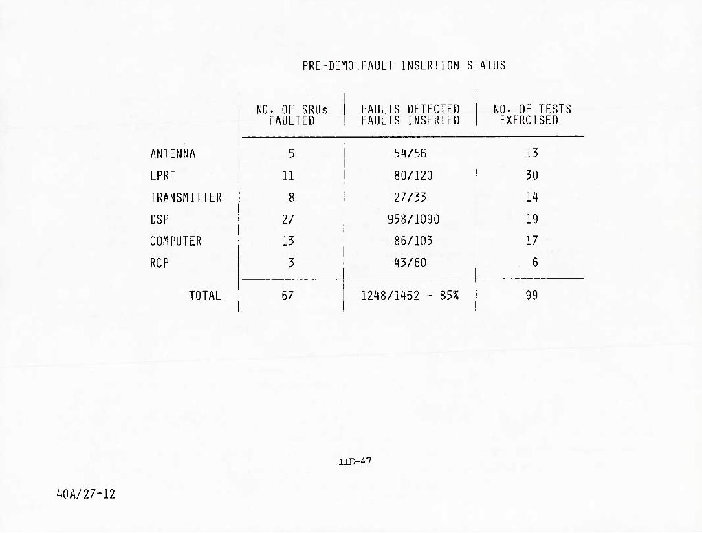
PRE-DEMO FAULT INSERTION STATUS
ANTENNA
LPRF
TRANSMITTER
DSP
COMPUTER
RCP
TOTAL
NO. OF SRUs FAULTED
FAULTS DETECTED FAULTS INSERTED
NO. OF TESTS EXERCISED
5 54/56 13
11 80/120 30
8 27/33 14
27 958/1090 19
13 86/103 17
3 43/60 6
67 1248/1462 = 85% 99
IIE-47
40A/27-12
DT&E FLIGHT TEST
The DT&E (FSD) flight test effort was accomplished using several airplanes over a 2-1/2
year period. Several organizations and bases were involved. Most of the testing was done
at Air Force bases with contractor support in varying degrees.
The pre-FSD testing began during the Air Force sponsored flight test model evaluation,
first by the two radar competitors—Hughes and Westinghouse, and later by the winner—
Westinghouse. The purpose of this testing was to gather engineering data to evaluate end-
to-end radar performance in the air-to-air modes. Testing was in a relatively benign
environment using F-4 air vehicles with non-F-16 avionics.
The FSD flight test program tested the radar in the F-16 air vehicle with a full comple-
ment of avionics. Radar performance data were gathered during this period. Included in the
data were evaluations of the self test and built-in-test, reliability and maintainability.
As the testing procedures progressed, design changes were incorporated and tested. This
progress soon resulted in the installation of production hardware into the FSD flight test
program, and later, design changes to the production equipment. The testing satisfied all
the formal requirements of the air vehicle and procurement specifications.
Reliability and maintainability engineering personnel followed the DT&E flight test
through all phases. During the F-4 flights at fly-off competition at General Dynamics,
failure data were analyzed and utilized in the selection process. During F-16 radar flights
for development and R&M demonstration at General Dynamics and Edward AFB, R&M personnel
from GD and Westinghouse were assigned for data gathering, analysis and corrective action.
Hands-on maintenance was accomplished and maintenance times verified.
A large amount of the testing and evaluation was accomplished by the Multinational
Operational Test and Evaluation (MOT&E) group. This special Air Force testing organization
was located at Hill AFB, the first operational TAG base for F-16. The testing at Hill had
a heavy emphasis on self test/built-in-test evaluation, as well as overall radar usability
in the F-16 aircraft in a field environment using standard Air Force maintenance personnel,
facilities, and procedures.
IIE-48 40B/2-14

DT&E FLIGHT TEST
• TEST AIRCRAFT
ONE F-4 -T RADAR DEVELOPMENT
FOUR F-16S '- RADAR DEVELOPMENT
TWO FT16S " R&M DEMONSTRATION
• 181 FLIGHTS USING BRASSBOARD RADAR
• ^41 FLIGHTS USING FSD RADARS
1.2 HRS/FLT = 217
-1.5 HRS/FLT = 662
• 1241 FLIGHTS USING PRODUCTION RADARS ~1.5 HRS/FLT = ]M2
~ TOTAL 2741
••• PLUS AN ADDITIONAL -254 FLIGHT HOURS
SPECIFICALLY FOR RELIABILITY AND MAINTAINABILITY
^
in Wi M I 1 I 2
Wi u n 2 mi 1 o: ;^5-F^4 BRASSBOARD FLIGHT TEST
FSD FLIGHT ThTT
I •v-f--R&M DEMO
41/36 IIE-49

AN/APG-PRODUCTION IMPROVEMENTS
Initial APG-66 radar production deliveries to the F-16 aircraft started in June 1978.
As a result of these aircraft integration tests, RQT, and other engineering tests, a number
of hardware and software changes were instituted as depicted in the chart.
The first fleet activation occurred in January 1979 at Hill AFB, Utah. A number of
design problems were revealed as a result of the operator using modes in different roles
than anticipated, aircraft interface problems, and intermittent malfunctions due to system
transients. Design changes to correct these problems were incorporated into Configuration
B improvements.
In 1979, USAF user personnel requested additional changes in the ST/BIT mechanization.
GD/W/& MOT&E personnel met and set up a task team to test and evaluate a new ST/BIT
mechanization and submit a correction of deficiency system design change. The following
charts reflect the new ST/BIT mechanization. These design changes were flight tested at
Hill AFB, Utah, by MOT&E personnel and approved for fleet retrofit by SPO in the fall of
1979. After these changes, the number of flights occurring without an MFL increased from
35% in 1979 to 92% in the fall of 1982.
40C/1-18
IIE-50

AN/APG-66 Production Improvements
• Changes Required
- H/W Design . S/W Design - RQT . ST/BIT
12/78
• Field Data Showed: • A/Cinterfece
Problems - Operator
Usage T Intermllle'nts
S/W Changes Required
Intermlttents
8/79
• ST Changes Required for Pilot Reporting
• Minor H/W
• S/W Changes Required
10/79 11/80
2/80
4/79
I1-0104-BB-7
IIE-51

AN/APG-66 PRODUCTION IMPROVEMENTS
The overall objective of the team effort (GD/W/MOT&E) was to logically approach the
problems being experienced with ST/BIT on the Radar. The approach included three phases to
adequately define the problems based on field data collected at the time, evaluate potential
corrections and assure that they were consistent with USAF maintenance philosophies and then
develop an implementation approach to incorporate the changes into the F-16 aircraft fleet.
40 C/2-4 N, IIE-52
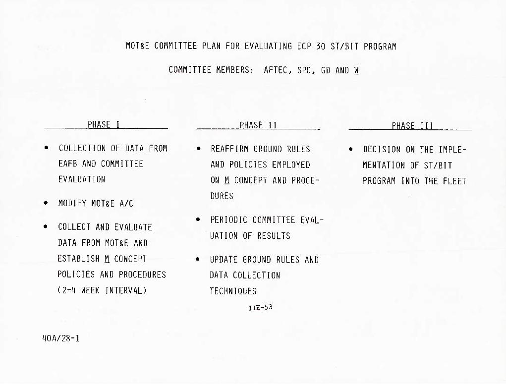
MOT&E COMMITTEE PLAN FOR EVALUATING ECP 30 ST/BIT PROGRAM
COMMITTEE MEMBERS: AFTEC. SPO. GD AND W
PHASE I PHASE II PHASE III
• COLLECTION OF DATA FROM
EAFB AND COMMITTEE
EVALUATION
• MODIFY MOT&E A/C
• COLLECT AND EVALUATE
DATA FROM MOT&E AND
ESTABLISH M CONCEPT
POLICIES AND PROCEDURES
(2-4 WEEK INTERVAL)
• REAFFIRM GROUND RULES
AND POLICIES EMPLOYED
ON M CONCEPT AND PROCE-
DURES
• PERIODIC COMMITTEE EVAL-
UATION OF RESULTS
• UPDATE GROUND RULES AND
DATA COLLECTION
TECHNIQUES
IIE-53
• DECISION ON THE IMPLE-
MENTATION OF ST/BIT
PROGRAM INTO THE FLEET
40A/28-1

MOT&E DATA ANALYSIS
The MOT&E conducted between March and December 1980 consisted of 1317 total flights.
Only 54 flights (4%) had catastrophic fault reports which led to the conclusion that previous
nuisance indicators of self test failures had been resolved.
IIE-54
40A/24-1

MOT&E DATA ANALYSIS
(3/80 TO 12/80)
1317 TOTAL FLIGHTS
54 FLIGHTS WITH CATASTROPHIC FAULT REPORT
40A/29-5 IIE-55

MOT&E DATA ANALYSIS
Additional analysis of MOT&E data suggest that only 11.5% of flights required Self
Test Fault Flag (STFF) usage (worst case). Once the Maintenance Fault Test Report was
cleared by LRU removal, everything worked. Performance, reliability, availability and
ST/BIT were all good. In addition, the STFF is a good indicator of system degradation.
40A/24-2 IIE-56

MOT&E DATA ANALYSIS
(3/80 THRU 12/80)
1317 FLIGHTS ANALYZED 9 A/C
IIE-57

MOT&E DATA ANALYSIS
The Avionic System ST/BIT concept implemented on newly developed hardware for the F-16
weapon system is characterized by two types of test(s): (1) Self-Test; automatic, non-
interruptive tests intended to detect failures or out-of-tolerance conductions and (2)
Built-in-Test; interruptive of normal operation and are used primarily to supplement ST in
isolating faults to an LRU. Further, the concept includes provisions to report malfunctions
to the pilot that: (1) require his attention or (2) reduce capabilities. The requirements
imposed on F-16 avionic subsystems include detection of 95% of malfunctions and isolation
of 95% of detected malfunctions to a single LRU.
The APG-66 Radar, instead of implementing ST/BIT at the LRU level (which may not have
been practical) implemented it at the system level which consisted of six (6) LRUs. This
coupled with the nature of Radar systems, in general, makes setting of sensitivity
thresholds for ST/BIT criteria difficult in a dynamic environment. The charts shown on
the next two pages indicate the results of early testing and the need for additional
development and refinement of ST/BIT for the Radar System.
IIE-58 40C/2-3

40A/29-2
WHAT WERE THE PILOT-NOTED PROBLEMS
AFFILIATED WITH SELF-TEST AND
BUILT-IN TEST? (BLOCK B)
SELF-TEST REPORTS OCCURRED IN-FLIGHT TOO OFTEN, ILLUMINATED
THE MASTER CAUTION LIGHT. AND THE PILOT DEBRIEF REPORT STATED:
- FREQUENTLY THE RADAR WORKED OK
- FREQUENTLY. CAN'T RUN BIT DURING FLIGHT. PARTICULARLY
AT TIME OF SELF-TEST FAILURE REPORT
- FREQUENTLY NO FAILURES NOTED WHEN BIT WAS RUN
- CONCLUSION: FAULTS REPORTED IN-FLIGHT BY SELF-TEST
^^--- WERE OF LIMITED VALUE TO THE PILOT
IIE-59

PILOT-NOTED PROBLEMS
For the Radar system, redefining the objectives of Self Test and Built-in Test in
view of the problems experienced in the field became necessary.
In that the Radar performed essentially end-to-end self-test of the system, fault
isolation to a single LRU by built-in-test proved to be difficult without additional
system level information. Many of the in-flight out-of-tolerance conditions detected
(either correctly or erroneously) were not duplicatable back on the ground in a non-
dynamic Radar environment. Because of the problem experienced early, confidence in ST/
BIT test as a measure of acceptable performance of the Radar was considerably reduced
and resulted in numerous manhours being expended in trying to duplicate problems. When
the Radar experienced hard failures/non-dynamic situations, Built-in-Test satisfactorily detected and isolated the problems during ground testing.
IIE-60 40C/2-2

APG-66 ST/BIT PROBLEMS INCURRED AT HAFB
WITH BLOCK B CONFIGURATION
• SELF-TEST REPORTS DO NOT PROVIDE AN INDICATION OF WHICH LRU IS DEFECTIVE
• FREQUENTLY P0STFLI6HT MAINTENANCE FAILS TO REPRODUCE IN-FLIGHT ST REPORTS
• SELF-TEST PROBLEM CREATED THE FOLLOWING SITUATIONS:
- PILOT HAS LITTLE CONFIDENCE IN SELF-TEST OR BUILT-IN TEST
- MANY MAINTENANCE HOURS SPENT TRYING TO DUPLICATE SELF-TEST/ BUILT-IN TEST REPORTS
- MANY CNDs AND RTOKs DUE TO "SHOT-GUN" REMOVAL OF LRUs
• BUILT-IN TEST IS NOT A PROBLEM
- LRUs REMOVED FOR BIT REPORT ARE USUALLY DEFECTIVE
IlE-61
^OA/29-1
F-16 APG-66 RADAR IMPROVEMENTS IN ECP-331
At the ECP 331 change block point several changes were made to the self test (ST) and
built-in-test (BIT) implementation. A number of detailed problems were uncovered and
corrected. These are listed on the facing chart. The corrections consisted of software
changes to permit proper sequencing and timing to prevent false reports. In a few isolated
cases, certain tests were masked when a failure was detected in other related tests.
A major re-mechanization was implemented for the ST. A separate radar list was
generated for reporting only radar self tests. These data were sent to the FCC for storage
and future recall. Additional technical order data were generated to enable maintenance
crews to utilize the ST data on the ground in conjunction with BIT reports and pilot com-
ments to better isolate failures to specific LRUs or to prevent the removal of LRUs when
the report was initially intermittent. The re-mechanization also increased the number of
catastrophic fault reports which are reported to the pilot via the master caution light
(MCL). And, in addition, a general report (ST fail) was removed from the MFL to prevent
nuisance occurrences to the pilot. As a result of this re-mechanization, the cannot
duplicate (CND) rate was reduced by approximately 3:1 from aircraft with the old mechaniza- tion.
IIE-62
40B/1-6
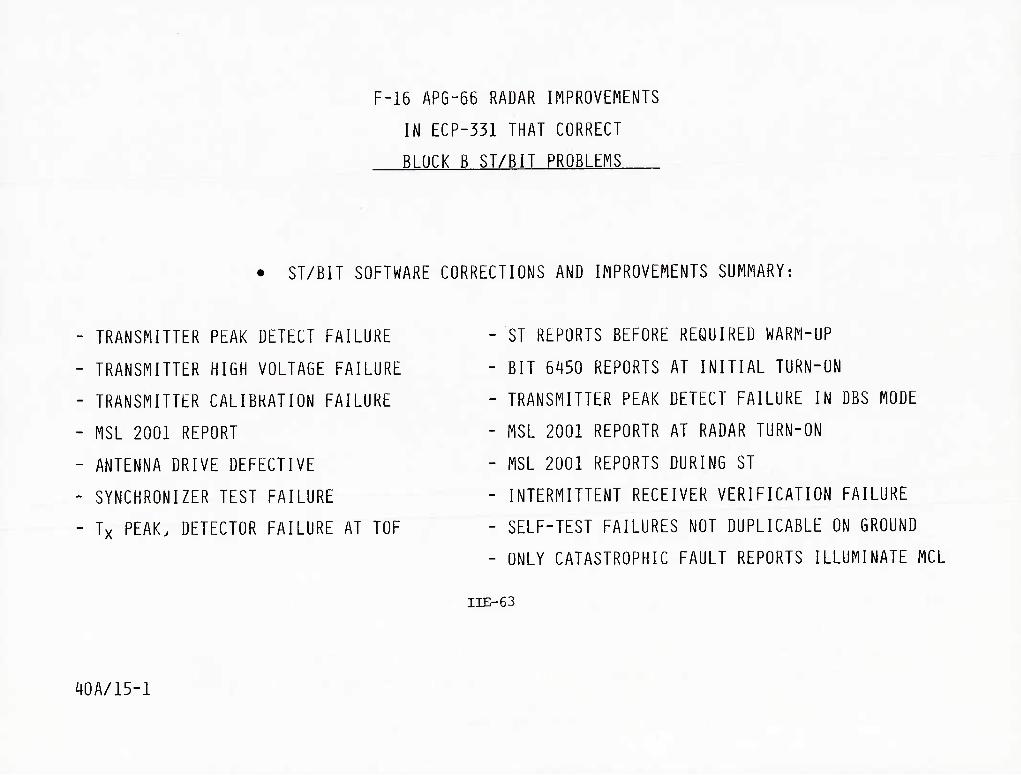
F-16 APG-56 RADAR IMPROVEMENTS
IN ECP-331 THAT CORRECT
BLOCK B ST/BIT PROBLEMS
ST/BIT SOFTWARE CORRECTIONS AND IMPROVEMENTS SUMMARY:
TRANSMITTER PEAK DETECT FAILURE
TRANSMITTER HIGH VOLTAGE FAILURE
TRANSMITTER CALIBRATION FAILURE
MSL 2001 REPORT
ANTENNA DRIVE DEFECTIVE
SYNCHRONIZER TEST FAILURE
Tx PEAK. DETECTOR FAILURE AT TOF
-ST REPORTS BEFORE REQUIRED WARM-UP
- BIT 6i|50 REPORTS AT INITIAL TURN-UN
- TRANSMITTER PEAK DETECT FAILURE IN DBS MODE
- MSL 2001 REPORTR AT RADAR TURN-ON
- MSL 2001 REPORTS DURING ST
- INTERMITTENT RECEIVER VERIFICATION FAILURE
- SELF-TEST FAILURES NOT DUPLICABLE ON GROUND
- ONLY CATASTROPHIC FAULT REPORTS ILLUMINATE MCL
IIE-63
40A/15-1

F-16 APG-66 RADAR IMPROVEMENTS
IN ECP-331 THAT CORRECTED
BLOCK B ST/BIT PROBLEMS (CONT'D)
• COMPUTER HARDWARE CHANGES TO ELIMINATE HANG-UP CONDITION (1005)
• ANTENNA FLIPPER HARDWARE CHANGE AND RETROFIT
• SYSTEM OFP SOFTWARE CHANGES THAT AFFECT ST/BIT
- SYSTEM CALIBRATION ROUTINES MODIFIED TO MEET OPERATIONAL SCENARIO
- TRANSMITTER PROTECTION AND CONTROL LOGIC MODIFIED
- ANTENNA OVERTEMPERATURE LOGIC MODIFIED
- A/C INTERFACE MODIFICATIONS - SQUAT SWITCH BOUNCE
-- ECS SHUTDOWN
-- INU DOWN ACCOUNTED FOR
- DSP INITIALIZATION HEADER WORD FIX
- COMPUTER HANG-UP RESTART LOGIC MODIFIED
40A/15-2 IIE-65

APG-66 RADAR IMPROVEMENTS
During and after the evaluation phase of field testing, a number of candidate changes
were identified (some flight tested) for inclusion in the hardware and software to improve
Radar ST/BIT reliability and utility.
A joint GD/W/AF decision was made with regard to incorporating needed changes into the
airborne hardware. The items listed on the facing page regarding ST/BIT were included in
ECP 331. The ST/BIT restructuring minimized the possibilities of CNDs while at the same
time improved the meaningfulness of faults reported to the pilot. The changes subsequently
restored pilot and ground maintenance crew confidence in Radar ST/BIT as a reliable
maintenance tool.
40C/2-1 IIE-66

CHANGES INCLUDED IN ECP-331 REGARDING SELF-TEST REPORTING SYSTEM
CATASTROPHIC FAULT REPORTS INCREASED TO 31 TESTS
6 WORDS (80 BITS) SENT TO THE FCC IN SELF-TEST, INDICATING THE FAILED PARAMETER
LOGIC CHANGE TO ELIMINATE ST REPORT FLAG FROM ILLUMINATING THE A/C MASTER CAUTION LIGHT
MASTER CAUTION LIGHT ILLUMINATES AS A FUNCTION OF CATASTROPHIC FAULTS, ONLY (1010)
MAINTENANCE FAULT LIST (MFD CONTINUES TO STORE lOlO's. 6002's. BIT REPORT NUMBERS,
AND THE NEW ST FAULT FLAG REPORTS
- NEW ST FAULT FLAG REPORTS STORED IN SEPARATE LIST (RST)
^OA/27-9 iiE-67

RELIABILITY GROWTH THROUGH ST/BIT
Performance and fault circumstance data obtained through the self test/built-in-test
capability of the radar allowed identification and correction of problem areas in field
use. The availability of the self test/built-in-test data permitted ST/BIT performance
analysis. This identified design improvements which improved reliability growth.
IIE-68
40A/2-1
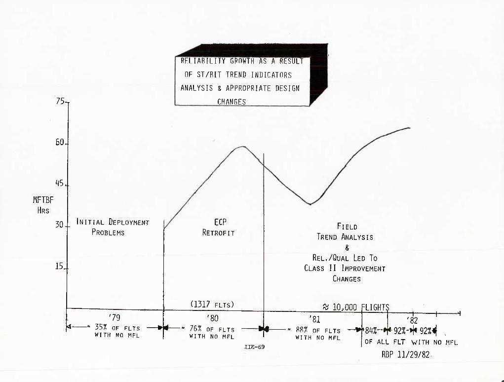
75-r
60-
^5..
FIFTBF HRS
30-
15.
INITIAL DEPLOYMENT
PROBLEMS
'79 y* "" 3S% OF FLTS N#-
WITH NO MFL
RFLIARILITY GROWTH AS A RESULI
OF ST/RIT TREND INDICATORS
ANALYSIS & APPROPRIATE DESIGN
CHANGES
ECP RETROFIT
(1317 FLTS)
'80 76% OF FLTS WITH NO MFL
FIELD
TREND ANALYSIS
& REL./QUAL LED TO
CLASS II IMPROVEMENT
CHANGES
^ 10.000 '81
f^8% OF FLTS WITH NO MFL
IIE-69
■LIGHTS
'82
8/^^-♦H•92%-H<92%lf OF ALL FLT WITH NO MFL
RDP 11/29/82.

IN-SERVICE ASSESSMENT
These figures show some selected data from in-service operations of the F-16 APG-66
radar. The chart shows MTBMA as a function of cumulative flight hours. Problems such as
the radar drive band breakage, chafing of the wire harness, and transistor failures in the
AZ compensation assembly prevented the results from attaining higher levels. As a result of
field data and laboratory evaluation of these problem areas, corrective action has been
identified and is being incorporated. The MTBMA trend is upward as the number of flight
hours passes 104,000. The 3-month moving average MTBMA by May 1982 is better than 60
hours.
IIE-70
40B/2-15

I see
APG-66 RADAR niBMA VS. CUMULATIVE FLIGHT HOURS
THPEE (3> HOHTH MOMINC AUERAGE Trt.f*CK OS Of. tlAV, 82 ■ UUC>r4AXX TYPE-1 EMSE-USMF F/C PAOHA SUntlARY
lOd
M T B M A
10
1 isaoe
CUMULATIUE n.ICHT HOURS
I" ^,''111/^
isooa?
IIE-71


LESSONS LEARNED
iii-i

Competition has many benefits —the most obvious being cost. When performance of the
requirements is linked with incentive (either monetary or assignment of additional liability),
the resolve to perform is emphasized early and stressed throughout the development and subsequent production phases.
The generation of requirements should follow a controlled logic supported by sufficient
rationale to justify the requirements. Contribution by all participants who can ultimately
agree on the requirements normally adds to the commitment that must be followed.
Good results are obtained when the government engages in cooperative efforts with the
reputable contractors to develop requirements, thereby avoiding unacceptable extensions of
the technological state of the art and causing unwarranted performance and reliability
expectations as well as high costs. Support requirements should also be a primary consid- eration in developing a new system concept.
The ability of contractors to be flexible during early development is enhanced by a
prime/sub relationship. This allows the two parties to make needed changes without having
to follow a lengthy chain of command. The integration of the APG-66 into the overall
weapon/aircraft system was much smoother due to the contractual arrangement used during the FSD and early production phases.
III-2 40C/1-19

LFSSONS (RE)LEARNEn
• COMPETITinW IS A KEY MOTIVATOR
• RELIABILITY AND MAINTAINABILITY MUST BE STATED AS
REQUIREMENTS -- NOT GOALS
• INCENTIVES WORK TO EMPHASIZE REQUIREMENTS
• DEVELOPMENT OF REQUIREMENTS REQUIRES PARTICIPATION
OF BUYERS AND SELLERS TO ASSURE THAT THEY ARE
RATIONAL AND REASONABLE
• MIL-STD-AZO NEEDS TO BE REVISED
• THE PRIME/SUB RELATIONSHIP OFFERS INTERFACE SIMPLICITY,
FLEXIBILITY. AND FREEDOM TO MAKE CHANGES IN THE FORMA-
TIVE STAGES OF THE PROGRAM
40A/28-2 III-3

Cost and/or liability incentives have a significant impact on the attention and commit- ment of high-level management.
A major part of the emphasis by management is the generation of development plans for
both R&M. These plans must be integrated with the system plans to be sure that the proper
attention is given to R&M. Without such planning the R&M functions may tend to become satellite activities.
In order to implement the R&M plans, the initial design team must include engineers to
fold maintainability and reliability into the inherent design and development process. It
is through their activities that the reguirements will be visible to the whole team.
The need for management of concurrent activities is normally dictated by reduced acqui-
sition cycles. The need to maintain follow-up of the various results of concurrent activities
requires an integrated knowledge of those results. All of the data from the activities
such as environmental qualification, reliability qualification, maintainability demonstrations,
etc., should be combined to form the appropriate corrective actions.
Asset management is a critical facet of concurrency. It is crucial that plans include
dedicated hardware for R&M testing and development. As the need for hardware always exceeds
the amount of hardware that is available, allocations must be planned and made. The exact
number of sets of hardware required is dependent on many factors. Data from hardware use
is needed for evaluation of the need for and adequacy of corrective action. Thus, the more
hardware actually in use, the better the analysis data base becomes.
III-4
40C/1-20

LESSONS (RE)L£ARNED
^OA/28-3
• MANAGEMENT EMPHASIS. INFLUENCED BY COST INCENTIVES.
IS A SIGNIFICANT DRIVING FORCE IN R&M SUCCESS
• R&M DEVELOPMENT PLANS MUST BE INTEGRATED WITH
SYSTEM DEVELOPMENT PLANS
• THE DESIGN TEAM MUST CONTAIN AS INTEGRAL MEMBERS
ST/BIT/MAINTAINABILITY ENGINEERS AND RELIABILITY
ENGINEERS
• CONCURRENCY CAN BE MANAGED
• DEDICATED HARDWARE FOR R&M GROWTH AND TEST MUST BE
PLANNED AND ALLOCATED
III-5

Parts selection and control are of prime importance in achieving high reliability and keeping low levels of maintenance.
The inclusion of the suppliers of the parts as members of the team is one way to
maintain their support. The main incentive for these suppliers is volume. Other types of
incentives are difficult to apply to piece part suppliers.
The specifications outlined for MIL-M-38510 parts are not sufficiently defined or
controlled for parts which must operate in high data rate applications. The screening
requirements for these devices are also inadequate. As a result, Westinghouse has imposed
100% testing of all such components over temperature to ensure that they will operate in the specific application.
While much effort and attention is being focused on higher technology for digital
devices very little attention is being focused on analog components for improved reliability
and performance. RF devices are components which deserve particular attention.
The ability to pass down R&M requirements is in many cases difficult to accomplish
because of the ability of many suppliers to accept such requirements without excessive
capital investments. Small businesses are of particular concern. In most cases significant
assistance is required to bring their manufacturing and quality capabilities up to their
design capabilities. The assistance from government personnel is also vital.
III-6 40C/1-21

LESSONS (RE)LEARNED
/40A/28-4
• MANUFACTURERS OF MILITARY PARTS MUST BE A PART OF THE
TEAM—VOLUME IS THE KEY INCENTIVE
• SCREENING AND CHARACTERIZATION OF PARTS IS NECESSARY
IN CURRENT AND FUTURE HIGH DATA RATE ELECTRONICS-
MIL-M-38510 AND MIL-STD-883 ARE NOT ENOUGH
• MAJOR EMPHASIS ON TECHNOLOGY IMPROVEMENTS IS ON
DIGITAL COMPONENTS-ANALOG DEVICES RECEIVE LESS
ATTENTION —PARTICULARLY RF DEVICES
• DOLLAR PERCENTAGES ARE SPECIFIED FOR SMALL BUSINESSES-
PASS DOWN OF REQUIREMENTS (MIL Q 9859. ETC) ALSO
SPECIFIED-TWO EXTREMES DICTATE ASSISTANCE
III-7

The application of development through IR&D in advance of firm requirements was of
significant importance toward the development of the APG-66. A major part of the activity
on the Westinghouse WX series radar was aimed at improved reliability and maintainability.
The tools of computer designs, thermal analyses, maintainability/reliability predic-
tions, trade-offs, etc., if properly applied, will provide a baseline design which has a
fundamental R&M capability. Without such a baseline the management of subsequent problems
becomes intolerable. The APG-66 has a sufficient base inherent in the early design to allow
for the management of problems and the subsequent corrective actions for those problems.
The development of the ST/BIT during the development of the radar was key to ensuring
that the maintainability requirements could be achieved. ST/BIT has proven to be an impor-
tant tool in evaluating the reliability of the radar. This is due largely to the fact that
the ST/BIT development was integral with the overall radar development.
The continuation of design support after development is important in determining cor-
rective actions throughout the production and operational phase. An understanding of this by cost analysts on production quotes is important.
III-8 40C/1-22

•
•
^OA/28-5
LESSONS (RE)LEARNED
• INDEPENDENT R&D IS A FEEDING FUNCTION FOR FUTURE IMPROVEMENTS
USE OF PRUDENT DESIGN TOOLS. ANALYSES. TRADE-OFFS. ETC. "
PROVIDE AN INHERENTLY GOOD DESIGN—A MUST FOR MANAGEMENT OF
PROBLEMS THAT OCCUR
• ST/BIT DEVELOPMENT. INTEGRATION AND CHECK-OUT MUST BE CONCURRENT
WITH SYSTEM PERFORMANCE DEVELOPMENT
DESIGN SUPPORT THROUGHOUT PRODUCTION IS ESSENTIAL FOR CORRECTIVE
ACTION
III-9

Lessons Learned (Continued)
Exposure to environment and insertion of faults prior to formal R&M tests is an
effective means of identification of problem areas which require corrective action.
Incorporation of such corrections prior to the tests provides for a thorough evaluation
during the testing.
For many years there has been concern about the differences between laboratory and
field reliability. The application of random vibration over environment has provided a
more accurate simulation of field conditions and allowed for corrective action which can
influence the field performance.
Continuous acceptance test procedure was accomplished during all reliability testing
at all environmental conditions with BIT activated at the end of each mode. The performance
measurements of the ATP can then be correlated to ST/BIT performance and each checked
against the other. Simulation of interfaces can also be accomplished to identify problem
areas.
Follow-on reliability testing on a periodic basis is an effective means of identifying
new problem areas. From the development phase through completion of reliability acceptance
testing new problems were identified in each test. Although the required reliability tests
have been completed, Westinghouse planned for and is continuing testing on a monthly basis
to assure that any new problems are identified and corrected.
The true evaluation of R&M requirements and their effectiveness is how well they are
being met in operational usage. Programs for this evaluation must be planned.
III-IO
40B/2-19

LESSONS (RE)LEARNED
•
•
•
•
aOA/28-6
RELIABILITY GROWTH AND MAINTAINABILITY PRE-DEMO ARE INVALUABLE
TOWARD GETTING EARLY LOOK AT POTENTIAL PROBLEMS AND IS AN
INTEGRAL PART OF TEST AND FIX
RANDOM VIBRATION DURING ENVIRONMENT BRINGS LABORATORY CLOSER
TO FIELD CONDITIONS
USE OF ATP RATHER THAN ABBREVIATED TEST DURING RELIABILITY
TESTING ENSURES ALL ELEMENTS ARE ASSESSED
FOLLOW-ON RELIABILITY TESTING PERIODICALLY DURING PRODUCTION
IS EFFECTIVE TOWARD IDENTIFYING NEW PROBLEMS AS WELL AS
MAINTAINING CONTROL ^ ^ ^
VALIDATION OF R&M REQUIREMENTS/EFFECTIVENESS MUST INCLUDE
OPERATIONAL USAGE
iii-ii

A key element of achieving continued reliability after development and qualification
is improving factory yields. Improved yield results in lower rework and handling which are
potential causes of failures. Additionally, Westinghouse experience has shown that factory
problems tend to show up again in the field. Productivity improvements also affect yield
and provide better field performance.
The monitoring of all in-house problems makes use of ST/BIT. This in turn allows for
changes to testing based on significant trends. By using ST/BIT to identify factory problem
a continuous evaluation of the effectiveness of ST/BIT is maintained.
Testing in the factory must be continually evaluated to determine that problems are
not only detected but the detection is at the lowest level possible. Since most tests are
controlled by approved documents, some flexibility must be allowed.
III-12
40C/1-23

40A/28-7
LESSONS (RE)LEARNED
• YIELD/PRODUCTIVITY IMPROVEMENTS ARE A DEFINITE FACTOR IN
OBTAINING GOOD RELIABILITY
• MONITORING OF IN-HOUSE PROBLEMS CAN MEASURE EFFECTIVENESS
OF ST/BIT AND ASSIST IN DETERMINING PROBLEM TRENDS
• MANUFACTURING TESTING MUST HAVE SOME FLEXIBILITY TO
ALLOW FOR REDUCTION OF PROBLEMS AT HIGHER LEVELS
III-13

The introduction of hardware into the operational environment introduces new variables
which can affect the R&M performance. Because of these variables it is vital that a
continuous evaluation of the field performance be maintained.
The normal government data are insufficient to allow for trend evaluation and subsequent
corrective action. In order to obtain such data it is important that planning be made to
obtain the field results.
Contractor engineering support in the field is critical to operational problem under-
standing, feedback and correction. Engineering support in the field has been provided by
both GD and Westinghouse since the beginning of the program and has significantly assisted
in solving interface problems, test equipment problems, T.O. problems, hardware and
operational problems. When the Air Force decided to eliminate contractor support in late
1982, Westinghouse management felt strongly that this support was necessary in the solution
of field problems and provided personnel at no additional cost to the government.
I-level testing is most critical from the point of view of accurate fault determination
and verification. Results of factory test and field experience dictate modification of
some tests and tolerances. Without this iterative process good units are tested bad and
bad units are tested good.
The training of maintenance personnel needs to be strengthened. This is particularly
important in light of the high turnover rate of technicians at a given location. Identifica-
tion of aircraft interface problems is sometimes a last resort. This at times results in
abnormal pull rates on specific aircraft.
The identification of a field problem and incorporation of corrective actions is
impeded by the flow of technical orders. Up to 12-18 months can elapse between the
identification of a problem and some relief getting to the user.
III-14
40C/1-24

LESSONS (RE)LEARNED
• FIELD PERFORMANCE EVALUATION IS MANDATORY FOR IMPROVING R&M
• NORMAL DATA ARE INADEQUATE
• RIW PROVIDED ONE POINT OF EARLY IDENTIFICATION OF FIELD
PROBLEMS
• CONTRACTOR ENGINEERING SUPPORT IN THE FIELD IS CRITICAL TO
OPERATIONAL PROBLEM UNDERSTANDING. FEEDBACK AND CORRECTION
•
•
ITERATION OF I-LEVEL TESTING IS CRITICAL TO EFFECTIVE AND
ACCURATE IDENTIFICATION OF FAULTS. SITE-TO-SITE VARIATIONS
IN GROUNDING AND POWER CREATE DIFFERENT TEST RESULTS
40A/28-8
TRAINING IS INADEQUATE; TURNOVER IS HIGH
THE FLOW OF FORMAL TECHNICAL DATA IS TOO SLOW. NO RAPID
VEHICLE EXISTS TO ALERT THE FIELD TO SPECIFIC PROBLEMS OR
METHODS FOR IMPROVING MAINTENANCE .
III-15

An improved method to incorporate required changes, particularly early in field opera-
tions, is needed to rapidly incorporate those changes to avoid unnecessary costs and mature
the systems earlier. The ECP route is very slow and costly to incorporate and unnecessarily
costly in maintenance actions required before incorporation. The RIW program on the radar
set the stage for a quicker change. However, it still proved very slow and a means was
found to incorporate quasi-Class II changes in production and retrofit if the test equipment
(AIS) was not affected. Commercial industry is far better in timeliness in correcting some
deficiencies at no cost to the customer.
A key element in overcoming some of the current inhibitors is a cooperative atmosphere
between the hardware contractor, the T.O. and I-level contractor, the aircraft contractor,
the SPO, and the users.
III-16
40C/1-25
LESSONS (RE)LEARNED
• CORRECTIVE ACTION IS KEY TO IMPROVING R&M
• CURRENT PRACTICES INHIBIT CORRECTIVE ACTIONS DUE TO
STRICT INTERPRETATION OF MIL-STD-i|83
• IN-LINE BREAK INTO PRODUCTION OF CORRECTIVE ACTION
WITH INCORPORATION INTO FIELD RETURNS HAS BEEN
MOST EFFECTIVE
• TEAM WORK BETWEEN ALL PARTIES IS A PREREQUISITE TO
- ACHIEVING SUCCESS "" * '
III-17
40A/28-9

Lessons Learned
Cost incentives are significant driving forces for obtaining management emphasis to
ensure R&M success. Cost incentives operative early in the program, structured to produce
significant R&M effort, can reduce life-cycle cost. Management must constantly be aware
of all problems in a program and be a driving force in the solution of those problems in
order to plan effectively to meet incentive objectives. Management emphasis is also a key
factor in working as a team rather than in an adversary relationship. The team effort was
a major contribution to the success of this program.
Contractor engineering support in the field is critical to operational problem under-
standing, feedback and correction. Engineering support in the field has been provided by
both GD and Westinghouse since the beginning of the program and has significantly assisted
in solving interface, test equipment, T.O., hardware and operational problems. When the
Air Force decided to eliminate contractor support in late 1982, Westinghouse management
felt strongly that this support was necessary in the solution of field problems and
provided personnel at no additional cost to the government.
III-18
40B/2-17
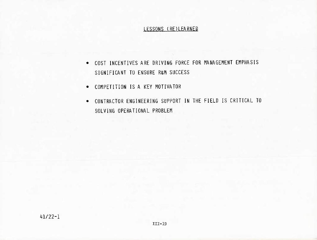
41/22-1
LESSONS (RE)LEARNED
• COST INCENTIVES ARE DRIVING FORCE FOR MANAGEMENT EMPHASIS
SIGNIFICANT TO ENSURE R&M SUCCESS
• COMPETITION IS A KEY MOTIVATOR
• CONTRACTOR ENGINEERING SUPPORT IN THE FIELD IS CRITICAL TO
SOLVING OPERATIONAL PROBLEM
III-19

Lessons Learned (Continued)
An improved method is needed to incorporate required changes, particularly early in
field operations to avoid unnecessary costs and to mature the systems earlier. The ECP
route is too slow and costly in maintenance actions required before incorporation. The
RIW program for the radar should have provided for quicker change, but the ECP approvals
were so slow that their purpose was circumvented by other actions.
Electrostatic sensitive devices are a problem that must be dealt with not only in the
manufacturer's plant but in field use as well. Early in the program it was discovered that
many electrostatic sensitive devices were not marked or packaged properly in normal prac-
tice. RNC resistors were a case in point, wherein the specification had to be changed to
have them marked and packed properly, which in turn made them a non-standard part. Special
attention was required by Westinghouse in setting up the manufacturing area to cope with
this problem in providing conductive materials in packaging work areas, grounding and the
control of humidity and operating procedures. The growth in new technology with smaller
and more sensitive devices will likely magnify this problem.
III-20 40B/2-18

40C/22-3
LESSONS (RE)LEARNED
AN IMPROVED METHOD TO INCORPORATE REQUIRED CHANGES IS NEEDED
(EXPEDITE)
ELECTRO-STATIC DISCHARGE CAN CAUSE DAMAGE TO MICROELECTRIC PARTS
AND ASSEMBLIES DURING MANUFACTURE AND REPAIR ACTIVITIES
- SOME DEVICES TODAY ARE NOT TREATED AS ELECTRO-STATIC
SENSITIVE THAT NEED TO BE
- ADDITIONAL PRECAUTIONS ARE NEEDED FOR I LEVEL AND DEPOT
LEVEL ACTIVITIES
III-21

Financial incentives, when appropriately applied, have the effect of motivating manage-
ment to act in the best interests of the government because they will also be acting in
their own best interests. The kinds of financial incentives that seemed to work effectively
in the case of the APG-66 radar are the following: Reliability Improvement Warranty (RIW),
guaranteed MTBF for selected subsystems, and reward or penalty sharing for surpassing
or falling short of requirements. Such sharing was extended contractually to the major
subcontractor. The proportions of sharing are shown on page IIA-9 of this report.
The APG-66 was highly concurrent in the sense that production started before full-scale
development was completed. The success seems to stem partly from the fact that WEC had
done a considerable amount of relevant design work before winning the contract for the
APG-66.
The amount of the financial incentive necessary to produce that extra bit of top manage-
ment interest is unclear. In the case of the APG-66, evidence supports the hypothesis that
top management will press to achieve each incentive since it tends to reflect on the overall
program and on their company reputation.
40B/2-21 III-22

41/22-2
I FSSQNS (RE)LEARNED (CONTINUED)
• GOOD UP-FRONT DESIGN MAKES LATER PROBLEMS MANAGEABLE
- CONTINUING ENGINEERING SUPPORT IS A LEGITIMATE AND NECESSARY
ACTIVITY AETER PRODUCTION BEGINS
• CONCURRENCY CAN BE MANAGED
• DEDICATED TEST ARTICLES ARE REQUIRED FOR R R M
• RELIABILITY MUST BE STATED AS A REQUIREMENT - NOT A GOAL
• SCREENING AND CHARACTERIZATION OF PARTS IS NECESSARY IN CURRENT
AND FUTURE HIGH DATA RATE ELECTRONICS APPLICATIONS. MIL-38510
IS NOT ENOUGH (MIL STD 883)
• FOLLOW-ON RELIABILITY TESTING ON A PERIODIC BASIS IS AN
EFFECTIVE MEANS OF IDENTIFYING NEW PROBLEM AREAS AND OF
MAINTAINING QUALITY THROUGH PRODUCTION
• RUN CONTINUOUS ATP DURING RELIABILITY TESTING
III-23

Lessons Learned
Development for the APG-66 did not originate at the moment that a military requirement
was stated for it. It originated considerably before that time, partly through IR&D that
resulted in developing a prototype of the system. This "pre-development" activity reduced
risks by helping to train the designers for the specific kind of equipment that would
become the APG-66.
It also is apparent that competition produces better equipment at lower cost. Hence
proposals should be sought from as many potential contractors as are available.
III-24
40B/2-20

LESSONS LEARNED
• CONTRACT
- SUPPORT IR&D
- ENCOURAGE COMPETITION
- DEVELOP SYSTEM REQUIREMENTS COOPERATIVELY (GOVERNMENT & INDUSTRY)
- REQUIREMENTS SHOULD REFLECT SUPPORT CONSIDERATIONS
• FINANCIAL INCENTIVES CAN BE USED TO PROMOTE R&M
• KEEP CONTRACTS SIMPLE. ALLOW FLEXIBILITY TO MAKE CHANGES EARLY
IN PROGRAM
THE LEVEL OF FINANCIAL INCENTIVE APPEARS TO BE SECONDARY IN IMPORTANCE
III-25 i|0A/27-2

Lessons Learned (Continued)
Management commitment to quality is important to producing a good product. More-
over, the commitment must be at a high enough level of management to influence all relevant
operations (i.e., no conflict must arise between the company components that are required
to produce high-quality installed equipment and those components whose job is to sell
spares).
In the F-16 program, both WEC and GD set up parallel project organizations. Another
factor was that teamwork among the prime and subcontractors and their suppliers was estab-
lished early and maintained throughout the program. In the final analysis, people resolve
problems.
III-26
40B/2-22

LESSONS LEARNED
• MANAGEMENT
- MANAGEMENT MUST SUPPORT R&M IF R&M IS TO RE ACHIEVED
- THE MANAGEMENT ORGANIZATION SHOULD PROVIDE THE Q&RA MANAGER
AUTHORITY TO GET THE JOB DONE
- EMPHASIS MUST INCLUDE THE INTEGRATION OF R&M AS A REQUIRED
CHARACTERISTIC OF THE EQUIPMENT UNDER DEVELOPMENT
- PRIME CONTRACTOR AND SUBCONTRACTORS AND THEIR SUPPLIERS WORKING
AS A TEAM HAVE THE BEST CHANCE OF PRODUCING RELIABLE EQUIPMENT
III-27
^OA/27-4

40A/27-5
LESSONS LEARNED
• DESIGN
- EMPHASIZE GOOD DESIGN UP FRONT (EARLY)
- SCREEN AND CHARACTERIZE ALL PARTS IN ALL HIGH DATA RATE
ELECTRONIC APPLICATIONS
- EMPHASIZE THE USE OF VARIOUS ANALYTICAL TOOLS (E.G.. TRADE
STUDIES) BY DESIGN ENGINEERS
- EMPHASIZE THE USE OF ALL OTHER TOOLS BY DESIGN ENGINEERS
THAT ARE AVAILABLE TO SUPPORT RELIABLE AND MAINTAINABLE DESIGNS
- ENSURE THAT DESIGN ALTERNATIVE STUDIES INCLUDE ATTENTION TO R&M
CHARACTERISTICS
- ST/BIT DEVELOPMENT. INTEGRATION. AND CHECK-OUT SHOULD BE CONCURRENT
WITH SYSTEM PERFORMANCE DEVELOPMENT
- ST/BIT DEVELOPMENT REQUIRES THE ASSIGNMENT OF PERSONNEL AND
EQUIPMENT ASSETS
- MAKE ST/BIT/MAINTAINABILITY ENGINEERS AN INTEGRAL PART OF THE
DESIGN TEAM WITH SUFFICIENT ASSETS COMMITTED TO DO THE JOB
III-29

Lessons Learned (Continued)
Sometimes, the notion of testing is discarded after a program gets into production.
Of course, testing is extremely important during the production of any system and especially
during the production of high-performance electronic systems. The testing that must be
done includes environmental stress screening at all levels of the production line—from
parts through LRUs. The parts control program must be energetically enforced to ensure and
maintain quality. And reliability acceptance tests, which usually occur early in the
production program, if continued can uncover problems that might creep into the hardware.
The number of systems to be tested under such a program is variable.
The damage that can be done by electrostatic discharge during normal handling of modern
electronic devices mandates that the potential for damage be controlled. Through packaging
and methods of discharging static electricity from workers and tools, parts and assemblies
handled during manufacture, testing and repair can be protected.
Problems in the field that are environmentally related invariably appear. Additional
environmental tests may be called for during early stages of production to handle problems
identified in field use.
III-30
40B/2-24

LESSONS LEARNED
• MANUFACTURING
- THE EXTENSIVE USE OF ESS AND IMPLEMENTATION AT ALL LEVELS OF THE
PRODUCTION PROCESS FROM INCOMING PARTS TO LRUs IS EFFECTIVE
- AN AGGRESSIVE PARTS CONTROL PROGRAM PAYS BIG DIVIDENDS
- AN ELECTROSTATIC DAMAGE PREVENTION SYSTEM IN PRODUCTION AND IN
THE FIELD IS NECESSARY
- CONTINUE RELIABILITY TESTING THROUGH THE PRODUCTION PROGRAM
^OA/27-6 III-31

Lessons Learned (Continued)
Historically, ST/BIT testing always gets a lower priority than the classic performance
tests. This lower priority is partly driven by the lack of assets. Therefore, systems
should be dedicated to early evaluation of R&M functions. Tests should include ST, BIT,
growth and environmental testing.
The presence of contractor personnel at operating bases is important in maintaining
the operational availability of the fleet of aircraft, since they are capable of providing
quick fixes. Moreover, they also provide an important information system for the contractor
that enables the designers to effect rapid improvement in the product after it is fielded.
Environmental chambers at the Intermediate Shop level, particularly for cold soak,
relatively simple and inexpensive, could help to avoid reinstalling potentially defective
parts and assemblies in repaired LRUs. They would also be very helpful in finding problems
associated with RETOKS with reliable fault reporting.
III-32
40B/2-25

LESSONS LEARNED (CONT)
TEST AND EVALUATION
- EARLIER R&M TESTING IF PLANNED. FUNDED. AND IMPLEMENTED FOR FSD CAN BE
BENEFICIAL TO RELIABILITY MATURATION
- GROWTH TESTING DURING FSD CAN MINIMIZE THE PROBLEMS CAUSED BY A CONCURRENT
PROGRAM
- DEDICATED R&M TEST ARTICLES FOR FSD AND PRODUCTION TESTING ARE VERY
IMPORTANT TO A CONCURRENT PROGRAM
- MAINTAINABILITY TESTS WITH ENOUGH SIMULATED FAULTS TO PROVIDE A RELIABLE
SAMPLE OF THE EFFICACY OF THE SYSTEM FAULT DETECTION AND ISOLATION IS
NECESSARY TO MATURE slTSlNi^YSTEM
- THE COLLECTION OF R&M DATA AT GOVERNMENT FACILITIES FOR THE PURPOSE OF
PRODUCT IMPROVEMENT IS ESSENTIAL TO MATURING THE SYSTEM
- COLD SOAK CHAMBERS AT THE INTERMEDIATE SHOP LEVEL MAY SOLVE MANY PROBLEMS
AT I-LEVEL RATHER THAN ?????
III-33
40A/27-7

f>0
o so