underbalanced drilling technology with air injection … drilling technology with air injection...
TRANSCRIPT

ORIGINAL PAPER - PRODUCTION ENGINEERING
Underbalanced drilling technology with air injection connector
Jiansheng Jiang • Fazle Rabbi • Qingsheng Wang
Received: 29 January 2013 / Accepted: 4 November 2013 / Published online: 19 November 2013
� The Author(s) 2013. This article is published with open access at Springerlink.com
Abstract Underbalanced drilling technology has been
extended deeply into every corner of the industrial pro-
ductions and processes. In particular, the technology has a
wide range of applications in oil and gas industries for the
product design, manufacturing and construction process. In
this work, a new air injection connector system has been
developed for underbalanced drilling. The system devel-
opment includes five key issues: original design, manu-
facturing control, experimental method, on-spot drilling
design, and field work point control. The air injection
connector system plays an important role and can signifi-
cantly reduce potential losses during the drilling process.
Keywords Underbalanced drilling � Air injection
connector � Process control � Horizontal well � On-site
procedure
Introduction
The underbalanced drilling technology has been regarded
as a good drilling technology for years (Omland et al.
2007). Major advancements have been made in the past
decades to determine the effects of adding particles to
drilling fluids (Luo et al. 2000). According to the report of
some oil companies, by using the underbalanced drilling
technology, horizontal well production increased ten times
compared with the conventional drilling technology (Liu
and Meng 2005). Nowadays, inflatable drilling fluid has
been widely used in the underbalanced drilling, either
through the riser or through the downhole air injection,
which usually works with compressed air from compressor
or booster (Rolf et al. 2001).
Downhole air injection technology involves parasitic
pipe, concentric pipe, drill string, and coiled tubing dril-
ling. In each method, compressed air, natural gas or
nitrogen is injected into the downhole drilling fluid. The
key technologies of underbalanced drilling are generating
and maintaining underbalanced conditions, well control
technology, ground processing of the produced fluids and
electromagnetic measure while drilling (MWD) technology
(Liu and Meng 2005). In recent years, the progress of
underbalanced drilling technology is mainly focused on
well control, drilling fluids, program design, and other
special tools (Rommetveit et al. 2005; Li and Yan 2005;
Chen et al. 2010; Zhang et al. 2009; Liu and Meng 2005;
Zhou et al. 2003).
In this work, a new underbalanced drilling tool called air
injection connector system with independent intellectual
property rights has been developed. The newly developed
underbalanced drilling tool has been applied to the field
work on horizontal well underbalanced drilling services. In
the on-site procedure, the air injection connector system
was put down into the well to realize the underbalanced
drilling. Details of the technology have been illustrated in
this work, which plays an important role in the on-site
procedure engineering design.
J. Jiang
Department of Mechanical Engineering, China University of
Petroleum, 102249 Beijing, China
J. Jiang � F. Rabbi � Q. Wang (&)
Department of Fire Protection and Safety, Boots & Coots Center
for Fire Safety and Pressure Control, Oklahoma State University,
Stillwater, OK 74078, USA
e-mail: [email protected]
F. Rabbi � Q. Wang
School of Chemical Engineering, Oklahoma State University,
Stillwater, OK 74078, USA
123
J Petrol Explor Prod Technol (2014) 4:275–280
DOI 10.1007/s13202-013-0089-3
The design of air injection connector system
The air injection connector system is also known as para-
sitic pipe joints. In the past, underbalanced drilling was
usually realized by the principle of the ‘‘U-tube’’, which
means another injection well must be made first to form a
‘‘U-tube’’ with the production well to inject high-pressure
air when the production well is being drilled. In order to
reduce the budget of drilling and to eliminate hazards with
few engineering work, the injection well was replaced by
the air injection connector system, which is connected on
the production casing at a predetermined position down
into the bottom of the well with the casing. It will then
open a valve to inject air into the casing ring space during
drilling to realize underbalanced drilling (Xian et al. 2009).
In order to meet the technical requirements of the above
process, the air injection connector system must consist of
a non-return valve to eliminate backflow. It must be sent
downhole together with the casing and be cemented dis-
posable with the casing. After completion of the first phase
of drilling process, the air injection connector could be
used to inject high-pressure air in the next phase of drilling
process. The pressurized air mixed with the drilling mud
would help to increase the performance of underbalanced
drilling (Fried et al. 1996; Bennion et al. 1998; Missel-
brook et al. 1991; Oyatomari et al. 2002).
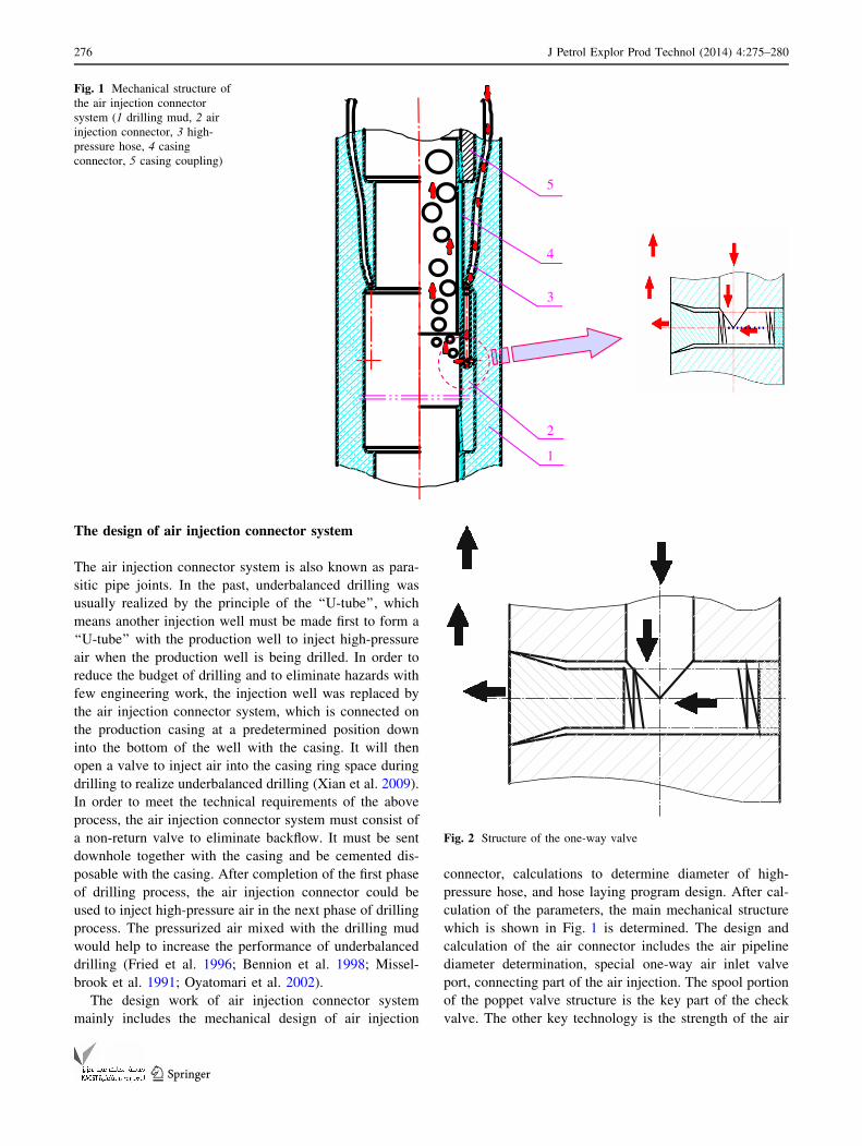
The design work of air injection connector system
mainly includes the mechanical design of air injection
connector, calculations to determine diameter of high-
pressure hose, and hose laying program design. After cal-
culation of the parameters, the main mechanical structure
which is shown in Fig. 1 is determined. The design and
calculation of the air connector includes the air pipeline
diameter determination, special one-way air inlet valve
port, connecting part of the air injection. The spool portion
of the poppet valve structure is the key part of the check
valve. The other key technology is the strength of the air
1
2
3
4
5
Fig. 1 Mechanical structure of
the air injection connector
system (1 drilling mud, 2 air
injection connector, 3 high-
pressure hose, 4 casing
connector, 5 casing coupling)
Fig. 2 Structure of the one-way valve
276 J Petrol Explor Prod Technol (2014) 4:275–280
123

pipeline, which should be subject to the greatest pressure.
Maximum working pressure of the hydraulic hose was set
at 70 MPa.
More attention should be paid to hazard elimination
during the tool design work, as the tool is the heart of the
air injection connector system. The structure of the poppet
valve spool section is especially important for the one-way
valve. The line between the spool and the valve body
(casing wall) ensures the sealing effect of the one-way
valve. The left side of spool close to the casing wall
ensures that cementing mud does not bond with the inside
surface of the valve body. These ensure the safety and
reliability of the reverse air injection use. This is the most
critical control point. The air injection connector system
will fail if the one-way valve does not work. The structure
of the one-way valve is shown in Fig. 2.
Manufacturing of the air injection connector
The quality control on the connector manufacturing
becomes more important after completion of the design of
the air injection connector. Firstly, the preparation of the
designed product was adopted. The strength of the material
was emphasized in the procedure of the manufacturing and
the mechanical process was also considered for the quality
of the tool. In addition to the specially designed one-way
valve, a standard one-way valve was fitted in the air
injection pipeline joints, which formed three secured bar-
riers together with the one-way valve on the ground air
compressor, which ensures the safety and reliability of the
underbalanced drilling.
The special one-way valve was commissioned by a pro-
fessional plant, which used a small batch trial processing.
Several technical improvements were made to form the
independent processing of the one-way valve’s mechanism
components. Eventually the unique structure was formed
with the monomer cone valve integrally embedded into the
check valve assembly, as shown in Fig. 3.
Indoor experiment
Pipeline joints were tested for probable leaks after com-
pletion of processing of the air injector connecting system.
The connected one-way valve should be leak-free along
with the spool piece during the pressure test. This is an
important part of the test for system safety issues. Gener-
ally, two dedicated casing male connectors are plugged
into the sealed air injection connectors at both ends, which
are then injected into the water with hydrostatic pressure
for test trials. The underground pressure may reach as high
as 20 MPa. Pressure test ensures the tightness of the special
one-way valve and reverse the operational reliability of the
air injection connector. The test will make sure there is no
leak and thus prevents future losses during drilling. Pres-
sure test is the most important step of process and loss
control during the manufacturing of the tools.
The structure of the air injection connector used in
indoor experiment is shown in Fig. 4. Several quality
control points were considered during the indoor experi-
ment. First, a fitting pressure test procedure was carried out
by injecting water into the connector and gradually sup-
pressing water with the pressure rising to 1 MPa without
leakage. After that the pressure of water was gradually
increased to 5, 10 and 20 MPa, each time holding the
pressure for 5 min. The system was relieved from pressure
when the joint portion test was completed without any
water leakage. Finally, the pressure test connector was
removed and the water was poured out of the connector
system. The indoor experimental setup is shown in Fig. 5.
The underbalanced drilling project design
Principle of air injection connector for underbalanced
drilling is similar to the principle of the ‘‘U-tube’’. The
high-pressure air passes through the ground high-pressure
air trachea, injection pipeline and air injection connector
into the annulus between the drill string and casing. The air
is mixed with the annulus drilling fluids and comes back to
the ground. Air injection into drilling mud decreases its
density. Thus, underbalanced drilling pressure is reduced,
and hence helps to achieve the requirement of the well in
coal seam. This working principle is shown in Fig. 6.
The key technology of the engineering project design is
the processing principle design and optimization design for
drilling parameters. Underbalanced drilling parameter
design mainly includes the choice of basic parameters,
drawing curve of the air injection pressure value of un-
derbalanced pressure of bottom hole and annulus air
injection, drilling fluid displacement, etc. (Hu et al. 2010).
Figure 7 shows the test well in different air injection
pressure conditions. The bottom hole underbalanced value
Fig. 3 The unique structure of the air injection connector
J Petrol Explor Prod Technol (2014) 4:275–280 277
123

curve changes with the annulus air injection and the dril-
ling fluid displacement.
When the injection pressure is constant, the bottom hole
pressure value increases with downhole drilling fluid flow
rates monotonically. And the larger the annulus gas injection
rate changes, the larger for absolute value of bottom pressure
value will be, the better it will be for the underbalanced
effect. In the same annulus gas injection rate, the greater the
drilling fluid flow rate changes, the smaller the absolute value
of bottom hole pressure will be, the underbalanced pressure
value will be lower. Under different injection pressure con-
ditions, the underbalanced effect is quite different at the
bottom of well. When the annulus gas injection rate Qg is
constant in a given calculation conditions, the higher injec-
tion pressure is, which is more closer to the coal reservoir
pressure, the gas injection effect will be better, when it can
achieve a lower underbalanced drilling pressure value more
easily in the reservoir.
Combined by the curves and field engineering require-
ments for underbalanced drilling, air injection pressure in
the range of 3.2–3.5 MPa can lead to a well bottom hole
formation due to a better balance. The optimum annulus air
injection pressure is stable at 3.5 MPa. Curve for the bot-
tom hole pressure in different amounts of gas injected and
liquid flow rates under injecting air pressure with 3.5 MPa
has been shown in Table 1.
On-site procedure and field work operation
After the successful trial tests of the air injection connec-
tors and auxiliary tools, the on-site procedure was
air pipeline and check valvePressure test connector air injection connector Pressure test plug
Fig. 4 Assembled structure of
the air injection connector
Fig. 5 Hydro test of the pipe joints with the air injection connector
Fig. 6 Underbalanced drilling
with air injection connector
278 J Petrol Explor Prod Technol (2014) 4:275–280
123

conducted on the coalbed methane drilling site in Qinshui
County, Shanxi Province, China. Some preparation for the
on-site works is required prior to the operation. For
example, a 95=8
00
casing dedicated circular iron plate was
machined, on which a hole was set each aside for air
injection pipeline penetrating down into the bottom of the
well. Some on-site auxiliary tools must be present in
advance to ensure the procedure in time. For example, the
ground air injection pipeline joints must be 27=8
00
standard
tubing connectors and the flow valve must be installed on
the booster’s outlet. The prepared actual length of the air
pipeline should be longer than the estimated length
approximately by 100 m. Before air injection connectors
going down, sufficient number of stainless steel clamps and
vices were used to fix the air pipeline around the casings. A
special cart should also be prepared to insert the air pipe-
line at the same time as that of the casing.
Workers should be trained on the on-site procedure and
field work operation. The workers should properly know
about the new tools and understand the main task of putting
down the air injection connector system in the proper
position under the well with the casings. Furthermore, all
the drilling parameters and the tool system itself should be
examined before proceeding to operation. The whole
operation is supervised by a manager, who is responsible
for the execution of the project. Air injection pipeline
should be kept closer to the casing wall while being sent
along with the casing. To keep the air pipeline closer to the
casing, special stainless steel clamps must be customized
for each 1–2 m of casing length. Special attention should
be given during this step and all the engineering practices
must be followed as per safety policy.
In the on-site procedure, the air injection connector had
been put 400 m under the hole. The actual injecting pres-
sure value was 3.5 MPa. The compressed air volume flow
was about 700 L/min. The underbalanced drilling process
with air injection connector had been realized as in the
example shown in Fig. 8. The on-site underbalanced dril-
ling was successfully and safely executed with an excellent
feedback.
Conclusion
The technology of underbalanced drilling has been well
used for tens of years and is still a good drilling
Fig. 7 Bottom hole underbalanced value curve changing with the
annulus air injection and drilling fluid displacement under different
air injection pressure
Fig. 8 Underbalanced drilling process with air injection connector
Table 1 Curve for bottom hole pressure DP in different amounts of gas injected and liquid flow rates under injecting air pressure with 3.5 MPa
Qw Qg
20 22 25 27 30 32 35 37
950 -0.1595 -0.2000 -0.2537 -0.2585 -0.3278 -0.3825 -0.4452 -0.5155
900 -0.1864 -0.2283 -0.2834 -0.3167 -0.3613 -0.4011 -0.4817 -0.5339
850 -0.2200 -0.2592 -0.3147 -0.3511 -0.3799 -0.4357 -0.5005 -0.5714
800 -0.2483 -0.2908 -0.3476 -0.3822 -0.3990 -0.4545 -0.5369 -0.5905
750 -0.2834 -0.3242 -0.3802 -0.4131 -0.4321 -0.4893 -0.5561 -0.6281
700 -0.3154 -0.3564 -0.4157 -0.4483 -0.4920 -0.5083 -0.5927 -0.6472
Qg is amount of annular injected air, m3/min; Qw is drilling liquid flow rates, L/s; DP is bottom pressure value, MPa
J Petrol Explor Prod Technol (2014) 4:275–280 279
123

technology. Using the air injection connector system in
underbalanced drilling gives the technology a higher edge.
The modification of the underbalanced drilling technology
helps to reduce the density of the drilling fluid. Compared
to the method of ‘‘U-tube’’ well for air injection, the par-
asite system with air injection connector is more econom-
ically feasible. Quality control plays an important role in
the tool design, manufacturing process, experiment, project
design, and the on-site procedure, all of which were illus-
trated in the technology of the underbalanced drilling air
injection connector system. As long as these controlling
methods and safety rules are followed, the on-site engi-
neering could be executed successfully.
Open Access This article is distributed under the terms of the
Creative Commons Attribution License which permits any use, dis-
tribution, and reproduction in any medium, provided the original
author(s) and the source are credited.
References
Bennion DB, Lunan B, Saponja J (1998) Underbalanced drilling and
completion operations to minimize formation damage––reservoir
screening criteria for optimum application. J Can Pet Technol
37(9):36–50
Chen FY, Hu T, Wang J (2010) Study and application of underbal-
anced drilling and completion technology with nitrogen gas in
heavy oil reservoir. J Drill Prod Technol 33(1):11–13
Fried S, Yurkiw F, Girgis M (1996). Gas supply alternatives and
corrosion considerations in underbalanced drilling operations.
Annual technical meeting, 10–12 June 1996
Hu ZJ, Hou FX, Ma QF (2010) An analysis of the process control
technology for drilling fluid continuous circulation system.
J China Pet Mach 38:62–65
Li TJ, Yan TN (2005) Problems of application of electromagnetic
wave MWD in underbalanced drilling. J Geol Sci Technol Inf
24(S1):37–39
Liu HX, Meng YF (2005) New technology to drill horizontal wells
with underbalanced pressure by air injection. J Pet Explor Dev
32(1):100–102
Luo SY, Meng YF, Li Y (2000) A study for mathematical model of
form underbalanced drilling in gas reservoir. J Nat Gas Ind
20(5):47–50
Misselbrook J, Wilde G, Falk K (1991). The development and use of a
coiled-tubing simulation for horizontal applications. SPE annual
technical conference and exhibition, Dallas, Tx, 6–9 Oct 1991,
pp 29–41
Omland TH, Saasen A, Taugbøl K (2007) Improved drilling process
control through continuous particle and cuttings monitoring.
Commence Soc Pet Eng: Digit Energy Conf Exhib SPE
107547:1–7
Oyatomari C, Orellan S, Alvarez R, Bojani R (2002). Application of
drilling fluid system based on air microbubbles as an alternative
to underbalance drilling technique in reservoir B-6-X.10––Tia
Juana, Lake Maracaibo. IADC paper presented at the interna-
tional association of drilling contractors ‘‘Global Leadership for
the Drilling Industry’’ conference in Madrid, Spain, May 2002,
pp 1–12
Rolf JL, Kjell KF, Johnny FR (2001) Underbalanced drilling: real
time data interpretation and decision support. SPE/IADC Drill
Conf 67693:1–9
Rommetveit R, Vefring EH, Wang ZH (2005) A dynamic model for
underbalanced drilling with coiled tubing. SPE/LADC Drill
Conf 29369:19–30
Xian BA, Zhao QB, Sun P (2009). Air injection connector for
underbalanced drilling. China Patent, ZL: 200820123709.0
Zhang Y, Xian BA, Zhao QB, Zhou WD (2009) Optimization of
annular gas injection technology in coalbed methane aerated
underbalanced drilling. J Pet Explor Dev 36(3):398–401
Zhou YC, Wang GX, Zhai HJ (2003) Application of underbalanced
drilling technology in Weishen-5 well of Daqing oilfield. J Acta
Pet Sin 24(6):90–97
280 J Petrol Explor Prod Technol (2014) 4:275–280
123