undergraduate engineers develop hydraulic servo control
TRANSCRIPT
www.mathworks.com
Model-Based Design with Simulink® and Real-Time Windows Target™ has changed the way we teach mechanical controls at California Polytechnic State University (Cal Poly) San Luis Obispo. In ME 422 - Mechanical Controls, a fast-paced intro-duction to control theory required of all seniors in the Mechanical Engineering department, students use MATLAB® and Simulink to process lab data and model and simulate open- and closed-loop systems. Because they have used the MATLAB en-vironment throughout their undergraduate studies, they hit the ground running in the course labs. Most important, Simulink and Real-Time Windows Target enable them to connect control design theory with practi-cal implementation by rapidly implement-ing a real-time controller prototype.
Course Overview Mechanical Controls consists of three one- hour lectures and one three-hour lab per week. Topics covered include single-input, single-output linear system modeling, time-domain analysis, transfer functions, root locus, frequency response methods, and proportional integral derivative (PID) and lead lag controllers.
Four lab experiments reinforce the top-ics covered in lecture. In the first three labs, students explore an analog DC servo position control, a two-tank water-level regulator, and a hydraulic servo control. Each lab experiment is completed in two consecutive weeks.
By Charles Birdsong, Ph.D., California Polytechnic State University at San Luis Obispo
In the past, control engineering was the exclusive province of computer
and electrical engineers with advanced degrees and years of experience in
low-level programming languages. Today, engineers and students alike can use
Model-Based Design to rapidly design and implement real-time control systems
without having to learn low-level programming. Used throughout the automotive
and aerospace industries, Model-Based Design places a high-level system
model at the center of development. This approach helps engineering students
understand not only the basic physics of system components, but also the inter-
action between components and the behavior of the overall system.
Undergraduate Engineers Develop Hydraulic Servo Control Systems Using Model-Based Design with Simulink
The final lab is a controller design project that gives the students the opportunity to apply the technical experience and back-ground they have gained throughout the course. Unlike the preceding labs, in which students have a full week between sessions to develop a controller, in the final lab the design is completed in a single session.
Lab WorkflowEach of the first three labs follows the same basic steps: system identification, system analysis, modeling, and simulation. The students measure the behavior of the system in open loop using a National Instruments PCI MIO 16E-4 data acquisition board to record system output for a range of input values. Their assignment is to use this sys-tem identification data to design a controller using classical methods—typically, root locus techniques.
Products Used ■ MATLAB®
■ Simulink®
■ Control System Toolbox™
■ Real-Time Workshop®
■ Real-Time Windows Target®
MATLAB Digest | AcAdemic edition
1 MATLAB Digest | AcAdemic edit ion
www.mathworks.com
Working in MATLAB, the students post-process the data by plotting the waveforms, calculating time constants, and so on. They then build and simulate an open-loop model of the system in Simulink. After comparing their simulation results with the real-world measurements, they build a closed-loop model of the system and test its performance through simulation. This approach rein-forces both the importance of classic control theory techniques and the value of simu-lating a closed-loop system to ensure that it is stable and safe before implementation.
The students submit a report for each lab, typically documenting their results with graphs and plots produced in MATLAB.
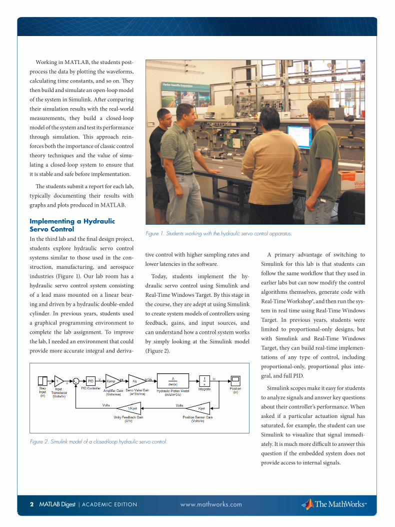
Implementing a Hydraulic Servo ControlIn the third lab and the final design project, students explore hydraulic servo control systems similar to those used in the con-struction, manufacturing, and aerospace industries (Figure 1). Our lab room has a hydraulic servo control system consisting of a lead mass mounted on a linear bear-ing and driven by a hydraulic double-ended cylinder. In previous years, students used a graphical programming environment to complete the lab assignment. To improve the lab, I needed an environment that could provide more accurate integral and deriva-
tive control with higher sampling rates and lower latencies in the software.
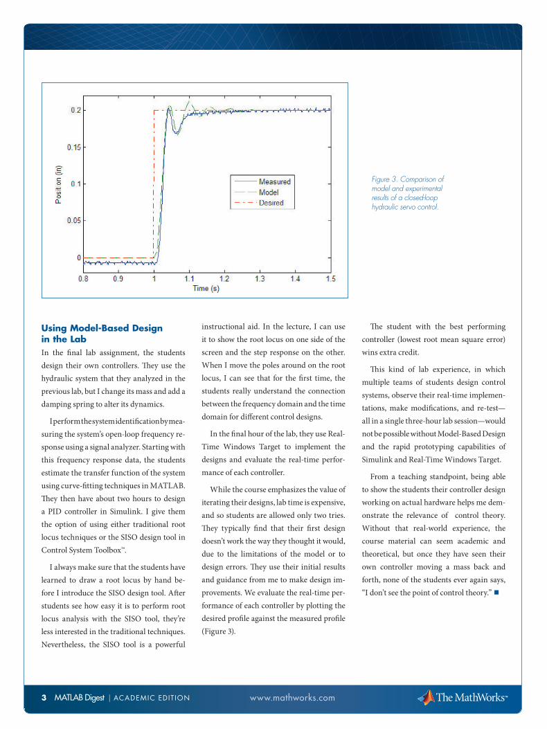
Today, students implement the hy-draulic servo control using Simulink and Real-Time Windows Target. By this stage in the course, they are adept at using Simulink to create system models of controllers using feedback, gains, and input sources, and can understand how a control system works by simply looking at the Simulink model (Figure 2).
A primary advantage of switching to Simulink for this lab is that students can follow the same workflow that they used in earlier labs but can now modify the control algorithms themselves, generate code with Real-Time Workshop®, and then run the sys-tem in real time using Real-Time Windows Target. In previous years, students were limited to proportional-only designs, but with Simulink and Real-Time Windows Target, they can build real-time implemen-tations of any type of control, including proportional-only, proportional plus inte-gral, and full PID.
Simulink scopes make it easy for students to analyze signals and answer key questions about their controller’s performance. When asked if a particular actuation signal has saturated, for example, the student can use Simulink to visualize that signal immedi-ately. It is much more difficult to answer this question if the embedded system does not provide access to internal signals.
2 MATLAB Digest | AcAdemic edit ion
Figure 1. Students working with the hydraulic servo control apparatus.
Figure 2. Simulink model of a closed-loop hydraulic servo control.
www.mathworks.com
Using Model-Based Design in the LabIn the final lab assignment, the students design their own controllers. They use the hydraulic system that they analyzed in the previous lab, but I change its mass and add a damping spring to alter its dynamics.
I perform the system identification by mea-suring the system’s open-loop frequency re-sponse using a signal analyzer. Starting with this frequency response data, the students estimate the transfer function of the system using curve-fitting techniques in MATLAB. They then have about two hours to design a PID controller in Simulink. I give them the option of using either traditional root locus techniques or the SISO design tool in Control System Toolbox™.
I always make sure that the students have learned to draw a root locus by hand be-fore I introduce the SISO design tool. After students see how easy it is to perform root locus analysis with the SISO tool, they’re less interested in the traditional techniques. Nevertheless, the SISO tool is a powerful
instructional aid. In the lecture, I can use it to show the root locus on one side of the screen and the step response on the other. When I move the poles around on the root locus, I can see that for the first time, the students really understand the connection between the frequency domain and the time domain for different control designs.
In the final hour of the lab, they use Real-Time Windows Target to implement the designs and evaluate the real-time perfor-mance of each controller.
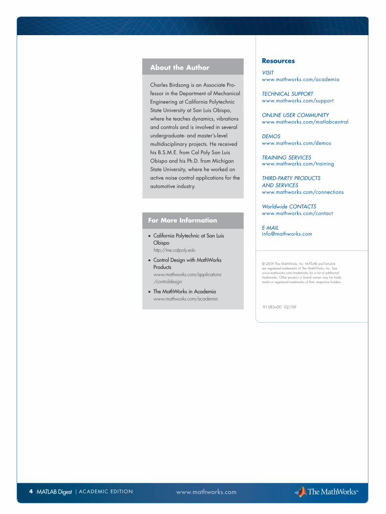
While the course emphasizes the value of iterating their designs, lab time is expensive, and so students are allowed only two tries. They typically find that their first design doesn’t work the way they thought it would, due to the limitations of the model or to design errors. They use their initial results and guidance from me to make design im-provements. We evaluate the real-time per-formance of each controller by plotting the desired profile against the measured profile (Figure 3).
The student with the best performing controller (lowest root mean square error) wins extra credit.
This kind of lab experience, in which multiple teams of students design control systems, observe their real-time implemen-tations, make modifications, and re-test—all in a single three-hour lab session—would not be possible without Model-Based Design and the rapid prototyping capabilities of Simulink and Real-Time Windows Target.
From a teaching standpoint, being able to show the students their controller design working on actual hardware helps me dem-onstrate the relevance of control theory. Without that real-world experience, the course material can seem academic and theoretical, but once they have seen their own controller moving a mass back and forth, none of the students ever again says, “I don’t see the point of control theory.” ■
Figure 3. Comparison of model and experimental results of a closed-loop hydraulic servo control.
3 MATLAB Digest | AcAdemic edit ion
MATLAB Digest www.mathworks.com
Resources
visit www.mathworks.com/academia
technical support www.mathworks.com/support
online user community www.mathworks.com/matlabcentral
Demos www.mathworks.com/demos
training services www.mathworks.com/training
thirD-party proDucts anD services www.mathworks.com/connections
Worldwide contactswww.mathworks.com/contact
e-mail [email protected]
91585v00 02/09
© 2009 The MathWorks, Inc. MATLAB and Simulink are registered trademarks of The MathWorks, Inc. See www.mathworks.com/trademarks for a list of additional trademarks. Other product or brand names may be trade-marks or registered trademarks of their respective holders.
For More Information ■ California Polytechnic at San Luis
Obispo http://me.calpoly.edu
■ Control Design with MathWorks Products www.mathworks.com/applications /controldesign
■ The MathWorks in Academia www.mathworks.com/academia
4 | AcAdemic edit ion
About the Author
charles Birdsong is an Associate Pro-
fessor in the department of mechanical
engineering at california Polytechnic
State University at San Luis obispo,
where he teaches dynamics, vibrations
and controls and is involved in several
undergraduate- and master’s-level
multidisciplinary projects. He received
his B.S.m.e. from cal Poly San Luis
obispo and his Ph.d. from michigan
State University, where he worked on
active noise control applications for the
automotive industry.