undergrouand fault detection
DESCRIPTION
asTRANSCRIPT
Underground Fault Detection 1
CHAPTER – 1
INTRODUCTION
Department of Electrical EngineeringAlpine Institute of Technology
Underground Fault Detection 2
The project uses the simple concept of OHMs law where a low DC voltage is applied at the
feeder end through a series resistor. The current would vary depending upon the length of
fault of the cable in case there is a short circuit of LL or 3L or LG etc. The series resistor
voltage drop changes accordingly which is then fed to an ADC to develop precise digital
data which the programmed microcontroller would display the same in Kilo meters. The
project is assembled with a set of resistors representing cable length in KMs and fault
creation is made by a set of switches at every known KM to cross check the accuracy of the
same.
.
SYSTEM DESIGN CALLS:
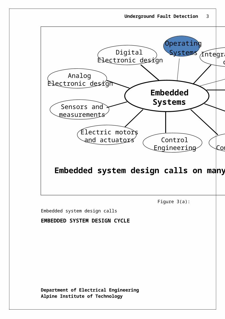
Figure 3(a): Embedded system design calls
EMBEDDED SYSTEM DESIGN CYCLE
Department of Electrical EngineeringAlpine Institute of Technology
EmbeddedSystems
ComputerArchitecture
SoftwareEngineering
Data Communication
ControlEngineering
Electric motorsand actuators
Sensors andmeasurements
AnalogElectronic design
DigitalElectronic design Integrated circuit
design
Embedded system design calls on many disciplines
Operating Systems
BuildDownload
DebugTools
Underground Fault Detection 3
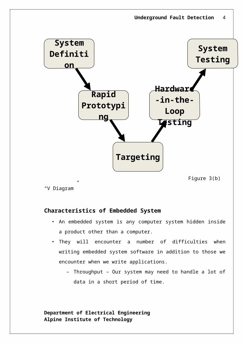
Figure 3(b) “V Diagram”
Characteristics of Embedded System
• An embedded system is any computer system hidden inside a product other than a
computer.
• They will encounter a number of difficulties when writing embedded system
software in addition to those we encounter when we write applications.
– Throughput – Our system may need to handle a lot of data in a short period
of time.
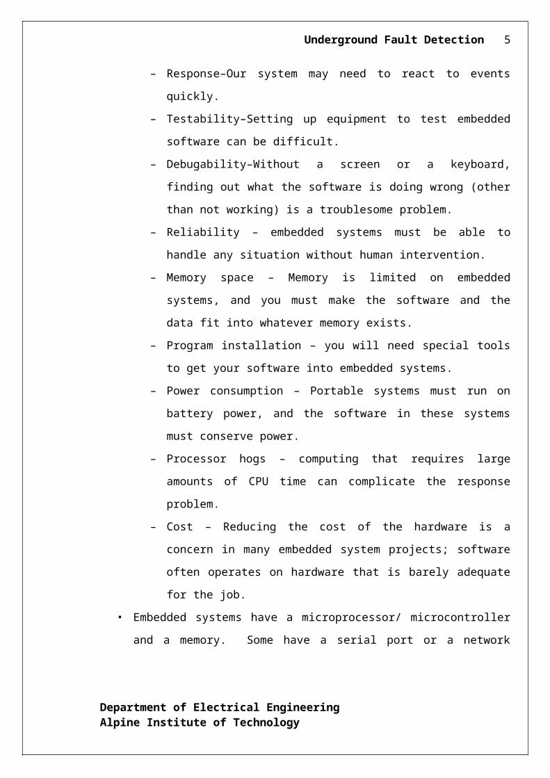
– Response–Our system may need to react to events quickly.
– Testability–Setting up equipment to test embedded software can be difficult.
– Debugability–Without a screen or a keyboard, finding out what the software
is doing wrong (other than not working) is a troublesome problem.
– Reliability – embedded systems must be able to handle any situation without
human intervention.
– Memory space – Memory is limited on embedded systems, and you must
make the software and the data fit into whatever memory exists.
– Program installation – you will need special tools to get your software into
embedded systems.
– Power consumption – Portable systems must run on battery power, and the
software in these systems must conserve power.
Department of Electrical EngineeringAlpine Institute of Technology
System
Testing
System
Definition
Targeting
Rapid Prototyp
ing
Hardware-in-
the-Loop Testin
g
Underground Fault Detection 4
– Processor hogs – computing that requires large amounts of CPU time can
complicate the response problem.
– Cost – Reducing the cost of the hardware is a concern in many embedded
system projects; software often operates on hardware that is barely adequate
for the job.
• Embedded systems have a microprocessor/ microcontroller and a memory. Some
have a serial port or a network connection. They usually do not have keyboards,
screens or disk drives.
APPLICATIONS
1) Military and aerospace embedded software applications
2) Communicat ion Appl ica t ions
3) Indust r ia l automat ion and process control sof tware
4) Mastering the complexity of applications.
5) Reduction of product design time.
6) Real time processing of ever increasing amounts of data.
7) Intelligent, autonomous sensors.
CLASSIFICATION
Real Time Systems.
RTS is one which has to respond to events within a specified deadline.
A right answer after the dead line is a wrong answer.
RTS CLASSIFICATION
Hard Real Time Systems
Soft Real Time System
HARD REAL TIME SYSTEM
"Hard" real-time systems have very narrow response time.
Example: Nuclear power system, Cardiac pacemaker.
Department of Electrical EngineeringAlpine Institute of Technology
Underground Fault Detection 5
SOFT REAL TIME SYSTEM
"Soft" real-time systems have reduced constrains on "lateness" but still must operate
very quickly and repeatable.
Example: Railway reservation system – takes a few extra seconds the data remains
valid.
3. PROJECT BLOCK DIAGRAM
Department of Electrical EngineeringAlpine Institute of Technology
Underground Fault Detection 6
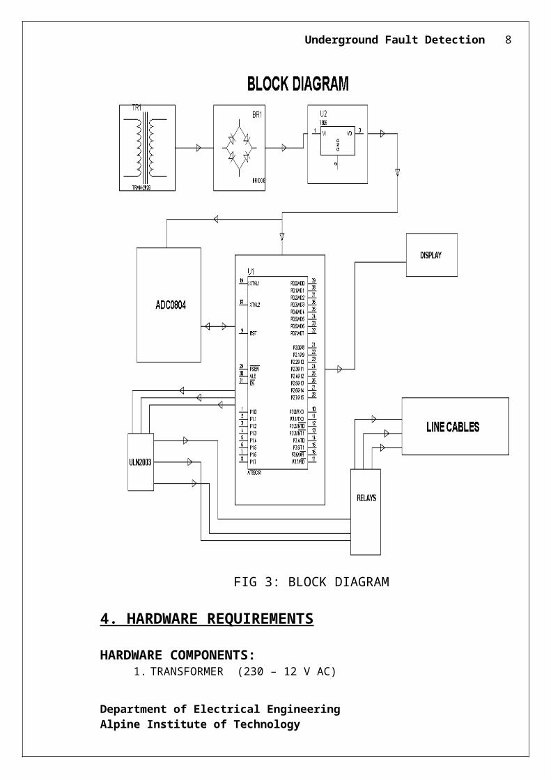
FIG 3: BLOCK DIAGRAM
4. HARDWARE REQUIREMENTS
HARDWARE COMPONENTS:1. TRANSFORMER (230 – 12 V AC)
Department of Electrical EngineeringAlpine Institute of Technology
Underground Fault Detection 7
2. VOLTAGE REGULATOR (LM 7805)
3. RECTIFIER
4. FILTER
5. MICROCONTROLLER (AT89S52/AT89C51)
6. LIQUID CRYSTAL DISPLAY
7. ADC0804
8. ULN2003
9. RELAYS
10. 1N4007
11. RESISTOR
12. CAPACITOR
2.2 COMPONENT DESCRIPTION
2.2.1 MICRO-CONTROLLER
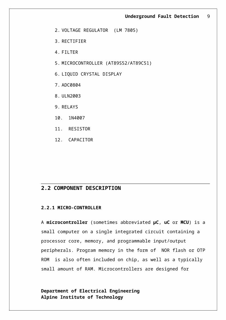
A microcontroller (sometimes abbreviated µC, uC or MCU) is a small computer on a
single integrated circuit containing a processor core, memory, and programmable
input/output peripherals. Program memory in the form of NOR flash or OTP ROM is also
often included on chip, as well as a typically small amount of RAM. Microcontrollers are
designed for embedded applications, in contrast to the microprocessors used in personal
computers or other general purpose applications.
Department of Electrical EngineeringAlpine Institute of Technology
Underground Fault Detection 8
Microcontrollers are used in automatically controlled products and devices, such as
automobile engine control systems, implantable medical devices, remote controls, office
machines, appliances, power tools, toys and other embedded systems.
2.2.2 LDR
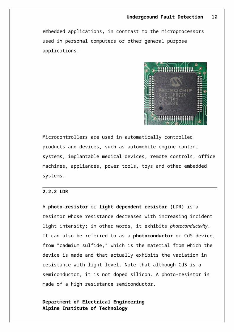
A photo-resistor or light dependent resistor (LDR) is a resistor whose resistance
decreases with increasing incident light intensity; in other words, it exhibits
photoconductivity. It can also be referred to as a photoconductor or CdS device, from
"cadmium sulfide," which is the material from which the device is made and that actually
exhibits the variation in resistance with light level. Note that although CdS is a
semiconductor, it is not doped silicon. A photo-resistor is made of a high resistance
semiconductor.
2.2.3 RESISTOR
Department of Electrical EngineeringAlpine Institute of Technology
Underground Fault Detection 9
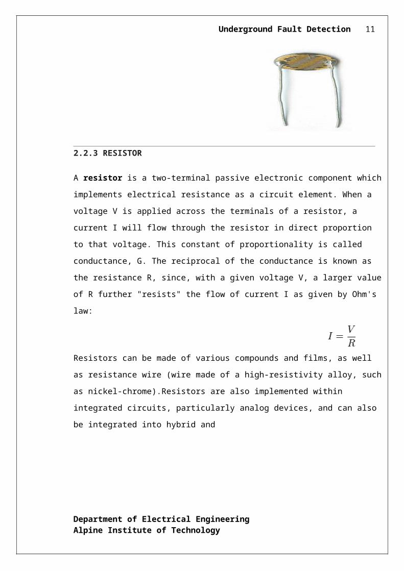
A resistor is a two-terminal passive electronic component which implements electrical
resistance as a circuit element. When a voltage V is applied across the terminals of a resistor, a
current I will flow through the resistor in direct proportion to that voltage. This constant of
proportionality is called conductance, G. The reciprocal of the conductance is known as the
resistance R, since, with a given voltage V, a larger value of R further "resists" the flow of
current I as given by Ohm's law:
Resistors can be made of various compounds and films, as well as resistance wire (wire made
of a high-resistivity alloy, such as nickel-chrome).Resistors are also implemented within
integrated circuits, particularly analog devices, and can also be integrated into hybrid and
2.2.3 CAPACITOR
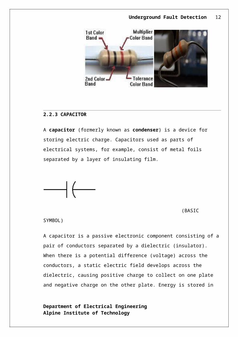
A capacitor (formerly known as condenser) is a device for storing electric charge.
Capacitors used as parts of electrical systems, for example, consist of metal foils separated
by a layer of insulating film.
(BASIC SYMBOL)
Department of Electrical EngineeringAlpine Institute of Technology
Underground Fault Detection 10
A capacitor is a passive electronic component consisting of a pair of conductors separated
by a dielectric (insulator). When there is a potential difference (voltage) across the
conductors, a static electric field develops across the dielectric, causing positive charge to
collect on one plate and negative charge on the other plate. Energy is stored in the
electrostatic field. An ideal capacitor is characterized by a single constant value,
capacitance, measured in farads. This is the ratio of the electric charge on each conductor to
the potential difference between them.
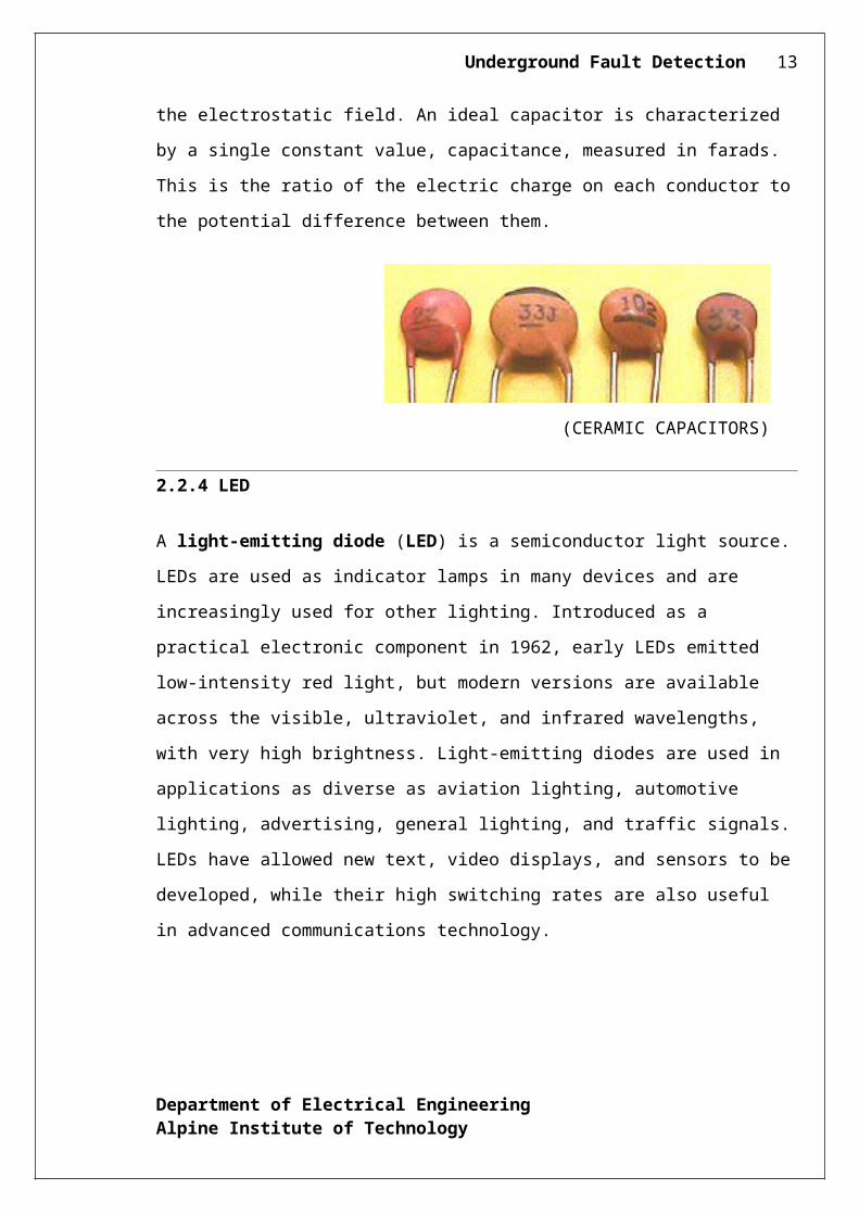
(CERAMIC CAPACITORS)
2.2.4 LED
A light-emitting diode (LED) is a semiconductor light source. LEDs are used as indicator
lamps in many devices and are increasingly used for other lighting. Introduced as a practical
electronic component in 1962, early LEDs emitted low-intensity red light, but modern
versions are available across the visible, ultraviolet, and infrared wavelengths, with very
high brightness. Light-emitting diodes are used in applications as diverse as aviation
lighting, automotive lighting, advertising, general lighting, and traffic signals. LEDs have
allowed new text, video displays, and sensors to be developed, while their high switching
rates are also useful in advanced communications technology.
Department of Electrical EngineeringAlpine Institute of Technology
Underground Fault Detection 11
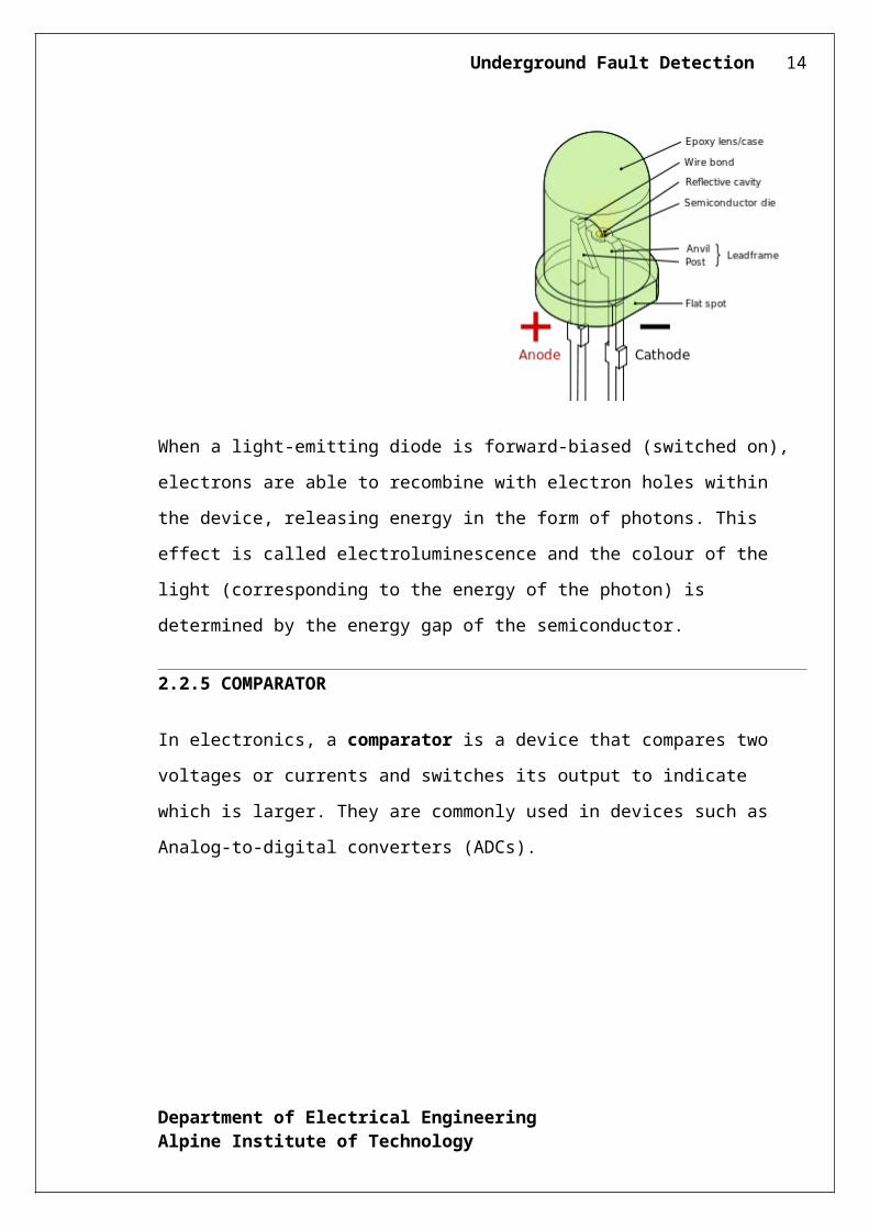
When a light-emitting diode is forward-biased (switched on), electrons are able to
recombine with electron holes within the device, releasing energy in the form of photons.
This effect is called electroluminescence and the colour of the light (corresponding to the
energy of the photon) is determined by the energy gap of the semiconductor.
2.2.5 COMPARATOR
In electronics, a comparator is a device that compares two voltages or currents and
switches its output to indicate which is larger. They are commonly used in devices such as
Analog-to-digital converters (ADCs).
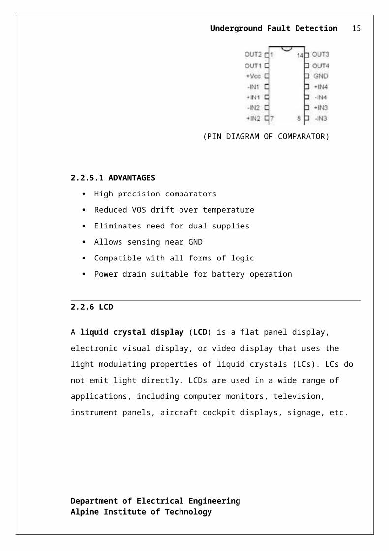
(PIN DIAGRAM OF COMPARATOR)
2.2.5.1 ADVANTAGES
High precision comparators
Department of Electrical EngineeringAlpine Institute of Technology
Underground Fault Detection 12
Reduced VOS drift over temperature
Eliminates need for dual supplies
Allows sensing near GND
Compatible with all forms of logic
Power drain suitable for battery operation
2.2.6 LCD
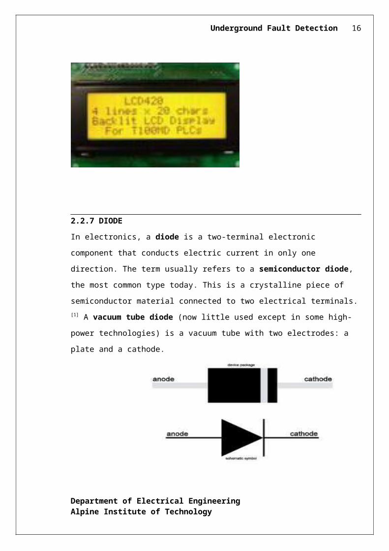
A liquid crystal display (LCD) is a flat panel display, electronic visual display, or video
display that uses the light modulating properties of liquid crystals (LCs). LCs do not emit
light directly. LCDs are used in a wide range of applications, including computer monitors,
television, instrument panels, aircraft cockpit displays, signage, etc.
2.2.7 DIODE
In electronics, a diode is a two-terminal electronic component that conducts electric current
in only one direction. The term usually refers to a semiconductor diode, the most common
type today. This is a crystalline piece of semiconductor material connected to two electrical
terminals.[1] A vacuum tube diode (now little used except in some high-power
technologies) is a vacuum tube with two electrodes: a plate and a cathode.
Department of Electrical EngineeringAlpine Institute of Technology
Underground Fault Detection 13
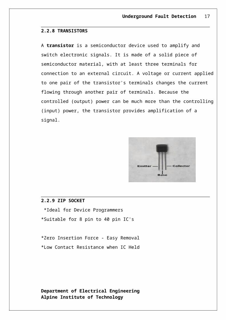
2.2.8 TRANSISTORS
A transistor is a semiconductor device used to amplify and switch electronic signals. It is made
of a solid piece of semiconductor material, with at least three terminals for connection to an
external circuit. A voltage or current applied to one pair of the transistor's terminals changes the
current flowing through another pair of terminals. Because the controlled (output) power can be
much more than the controlling (input) power, the transistor provides amplification of a signal.
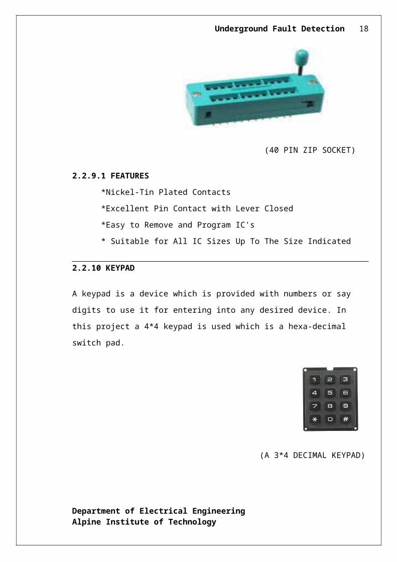
2.2.9 ZIP SOCKET
*Ideal for Device Programmers
*Suitable for 8 pin to 40 pin IC's
*Zero Insertion Force - Easy Removal
*Low Contact Resistance when IC Held
Department of Electrical EngineeringAlpine Institute of Technology
Underground Fault Detection 14
(40 PIN ZIP SOCKET)
2.2.9.1 FEATURES
*Nickel-Tin Plated Contacts
*Excellent Pin Contact with Lever Closed
*Easy to Remove and Program IC's
* Suitable for All IC Sizes Up To The Size Indicated
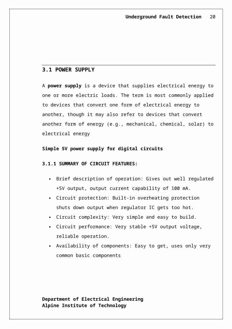
2.2.10 KEYPAD
A keypad is a device which is provided with numbers or say digits to use it for entering into
any desired device. In this project a 4*4 keypad is used which is a hexa-decimal switch pad.
(A 3*4 DECIMAL KEYPAD)
Department of Electrical EngineeringAlpine Institute of Technology
Underground Fault Detection 15
CHAPTER 3
HARDWARE
3.1 POWER SUPPLY
Department of Electrical EngineeringAlpine Institute of Technology
Underground Fault Detection 16
A power supply is a device that supplies electrical energy to one or more electric loads.
The term is most commonly applied to devices that convert one form of electrical energy to
another, though it may also refer to devices that convert another form of energy (e.g.,
mechanical, chemical, solar) to electrical energy
Simple 5V power supply for digital circuits
3.1.1 SUMMARY OF CIRCUIT FEATURES:
Brief description of operation: Gives out well regulated +5V output, output current
capability of 100 mA.
Circuit protection: Built-in overheating protection shuts down output when regulator
IC gets too hot.
Circuit complexity: Very simple and easy to build.
Circuit performance: Very stable +5V output voltage, reliable operation.
Availability of components: Easy to get, uses only very common basic components
Design testing: Based on datasheet example circuit, I have used this circuit
successfully as part of many electronics projects.
Applications: Part of electronics devices, small laboratory power supply.
Power supply voltage: Unregulated DC 8-18V power supply.
Power supply current: Needed output current + 5 mA.
Component costs: Few dollars for the electronics components + the input
transformer cost.
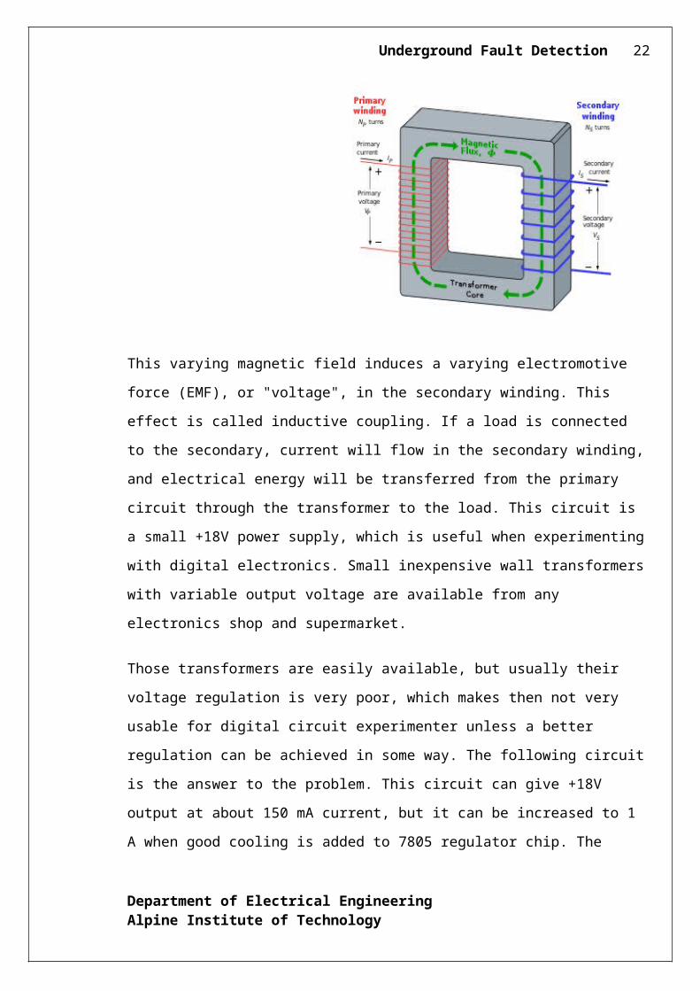
3.1.2 TRANSFORMER
A transformer is a device that transfers electrical energy from one circuit to another
through inductively coupled conductors—the transformer's coils. A varying current in the
first or primary winding creates a varying magnetic flux in the transformer's core and thus a
varying magnetic field through the secondary winding.
Department of Electrical EngineeringAlpine Institute of Technology
Underground Fault Detection 17
This varying magnetic field induces a varying electromotive force (EMF), or "voltage", in
the secondary winding. This effect is called inductive coupling. If a load is connected to the
secondary, current will flow in the secondary winding, and electrical energy will be
transferred from the primary circuit through the transformer to the load. This circuit is a
small +18V power supply, which is useful when experimenting with digital electronics.
Small inexpensive wall transformers with variable output voltage are available from any
electronics shop and supermarket.
Those transformers are easily available, but usually their voltage regulation is very poor,
which makes then not very usable for digital circuit experimenter unless a better regulation
can be achieved in some way. The following circuit is the answer to the problem. This
circuit can give +18V output at about 150 mA current, but it can be increased to 1 A when
good cooling is added to 7805 regulator chip. The circuit has overload and terminal
protection. The capacitors must have enough high voltage rating to safely handle the input
voltage feed to circuit.
3.2 PCB MANUFACTURING
Department of Electrical EngineeringAlpine Institute of Technology
Underground Fault Detection 18
3.2.1 WHAT IS PCB?
A PCB (printed circuit board) is a rigid flat board, which holds electronics component. This
board is made up of layers that interconnect component via a pathway.
3.2.2 HOW TO MAKE PCB?
Step I
Firstly arrange all of the component of the project & testing them for a proper working.
Step II
Perform pre –testing of circuit on bread board, if the circuit working properly then starts to
make PCB.
Step III
Draw the layout of circuit on inch graph paper with proper dimension Ensure that if
layout correct then draw it on trace paper. The layout can be traced on the board by screen
printing.
Step IV
Cut the CCB (Copper Clad Board) of the same size of layout.
Step V
Put the carbon paper on the PCB and trace from the reverse side of the layout Outline the
impression of layout on PCB and apply permanent marker.
Step VI (Etching):
Etching is the process in which excess layer of copper is removed to leave the
individual tracks as they are. The PCB plate is immersed in solution of FeCl3 + some
drops of HCL or H2So4. Shake it well till the copper is totally removed excepting the printed
layout path.
Department of Electrical EngineeringAlpine Institute of Technology
Underground Fault Detection 19
Step VII
After taking off the solution rinse the PCB plate with clean water and dry it. Then remove
the print layer with the help of thinner and a piece of cloth. Check the continuity of tracks
with the help of multimeter.
Step VIII
Drill the end points of the component on the lay out with the help of drill machine. Clean the
legs of the component with the help of sand paper tip it with the help of soldering iron. Place
the component as per circuit on PCB in the proper way.
Step IX
Apply Flux on legs of the component & solder them. Cut the remaining legs of the
components. Now the PCB is ready to connect the external power supply and the external
output or input devices.
3.2.3 SOLDERING
Soldering is the process of joining of two metals using an alloy solder consisting of Tin and
Lead (Sn-Pb). Tin determines the melting whereas the Lead issued to reduce the cost. After
the PCB fabrication is done, the various components are arranged at proper locations
on the PCB and then the soldering is done.
All liquids consist of particles which attract each other. The surface is always trying to
shrink and this is because of surface tension. The principle behind soldering is that when
liquid particles are brought in contact with the walls of the solid surface, it may
happen that the solid attracts the liquid surface adhesive property. Care must be taken that
the melting point of solder is below that of the metal so that its surface is melted without
melting without the metal.
3.2.3.1 NEED FOR FLUX
During the soldering process the flu for improving the degree of melting. The basic
functions of flux are mentioned x acts as a medium below:
Department of Electrical EngineeringAlpine Institute of Technology
Underground Fault Detection 20
1. Removes oxide from the surface.
2. Assists the transfer of heat from the source to the joining and provides a liquid cover
including air gap.
3. Removal of residue after the completion of the soldering operation.
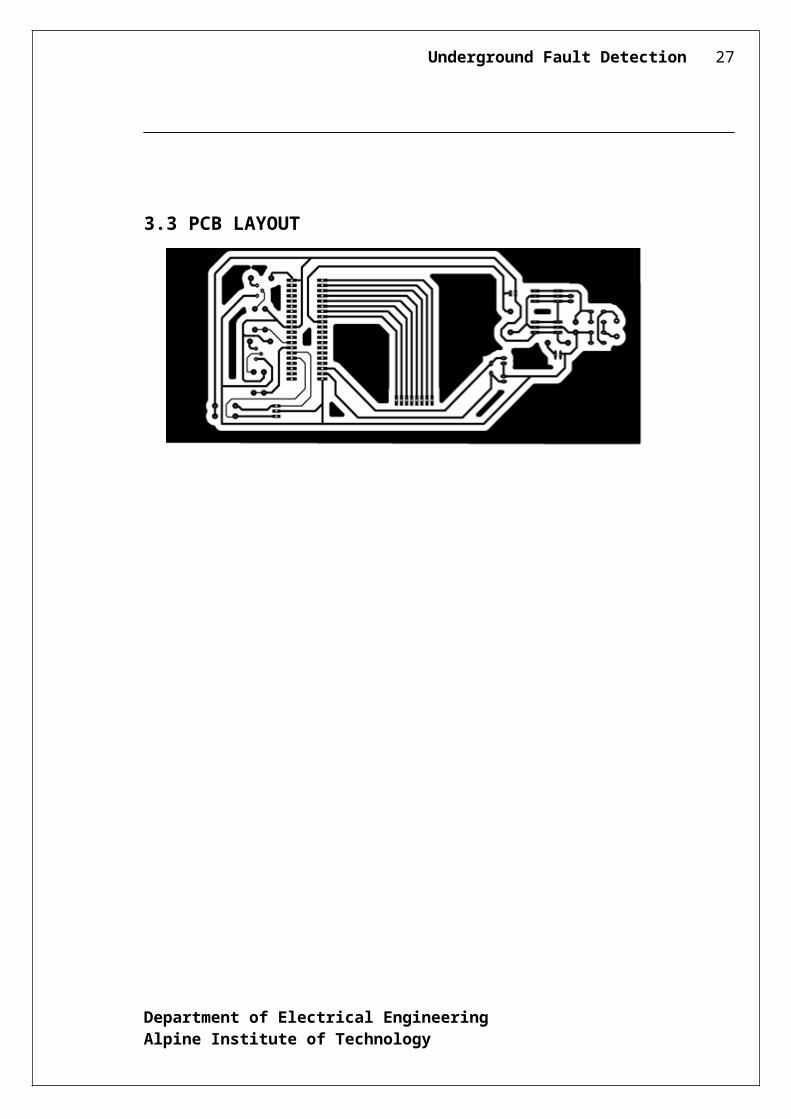
3.3 PCB LAYOUT
Department of Electrical EngineeringAlpine Institute of Technology
Underground Fault Detection 21
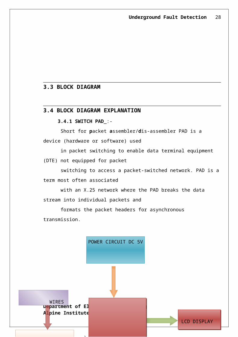
3.3 BLOCK DIAGRAM
Department of Electrical EngineeringAlpine Institute of Technology
Underground Fault Detection 22
3.4 BLOCK DIAGRAM EXPLANATION
3.4.1 SWITCH PAD :-
Short for packet assembler/dis-assembler PAD is a device (hardware or software) used
in packet switching to enable data terminal equipment (DTE) not equipped for packet
switching to access a packet-switched network. PAD is a term most often associated
with an X.25 network where the PAD breaks the data stream into individual packets and
formats the packet headers for asynchronous transmission.
Department of Electrical EngineeringAlpine Institute of Technology
WIRES
MICRO CONTROLLER P89V51RD2
POWER CIRCUIT DC 5V
LCD DISPLAY
INTERNAL ADC
Oscillator & Reset circuit
Underground Fault Detection 23
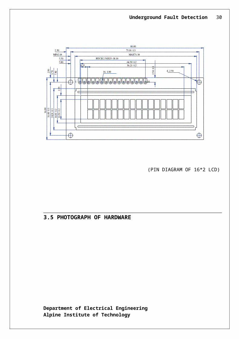
3.4.5 LCD DISPLAY:-
16 Characters x 2 Lines
5 x 7 Dots with Cursor
Built in Controller
+5v Power Supply (Also Available for +3V)
1/16 Duty cycle
Standard Type
Uses HD44780 Controller or Equivalent
Works with almost any Microcontroller
Great Value Pricing
(PIN DIAGRAM OF 16*2 LCD)
Department of Electrical EngineeringAlpine Institute of Technology
Underground Fault Detection 24
3.5 PHOTOGRAPH OF HARDWARE
CHAPTER 4
CIRCUIT DESCRIPTION
Department of Electrical EngineeringAlpine Institute of Technology
Underground Fault Detection 25
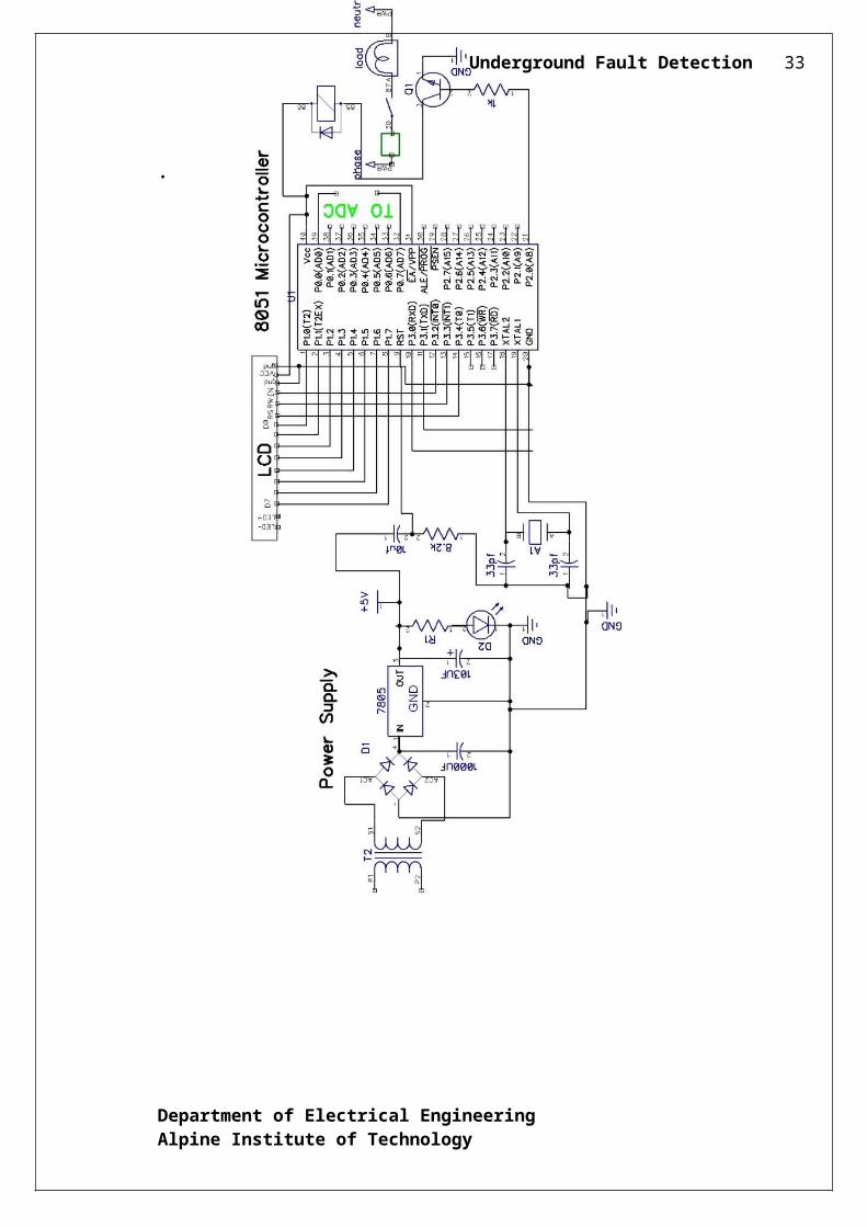
4.1 CIRCUIT DIAGRAM
Department of Electrical EngineeringAlpine Institute of Technology
Underground Fault Detection 26
.
Department of Electrical EngineeringAlpine Institute of Technology
Underground Fault Detection 27
CHAPTER 5
SOFTWARE
While any of the 12switches are operated they impose conditions like LG, LL, 3L
fault as per the switch operation. The program while executed continuously scan’s by
operating the 3relays in sequence of 1sec interval. Thus any NO point while driven to GND
through the common contact point of the relay develops a current flow through R1, R10 &
any other switch depending on the created fault. Thus the voltage drop at the ADC pin
varies depending on the current flow which is inversely proportional to the resistance value
representing the length of cable in kilometres. This varying voltage passes through the ADC
to develop a 8 bit data to the microcontroller port1 that while executed display’s an output
Department of Electrical EngineeringAlpine Institute of Technology
Underground Fault Detection 28
in the LCD display the fault occurring km. In a fault situation it display’s R=3km if the
3km’s switch is made ON. Accordingly all other faults are indicated.
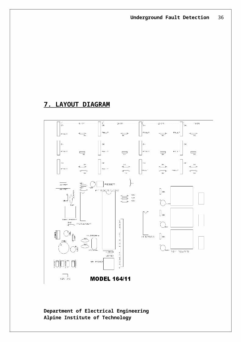
7. LAYOUT DIAGRAM
Department of Electrical EngineeringAlpine Institute of Technology
Underground Fault Detection 29
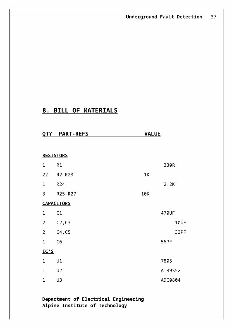
8. BILL OF MATERIALS
Department of Electrical EngineeringAlpine Institute of Technology
Underground Fault Detection 30
QTY PART-REFS VALU E
RESISTORS
1 R1 330R
22 R2-R23 1K
1 R24 2.2K
3 R25-R27 10K
CAPACITORS
1 C1 470UF
2 C2,C3 10UF
2 C4,C5 33PF
1 C6 56PF
IC'S
1 U1 7805
1 U2 AT89S52
1 U3 ADC0804
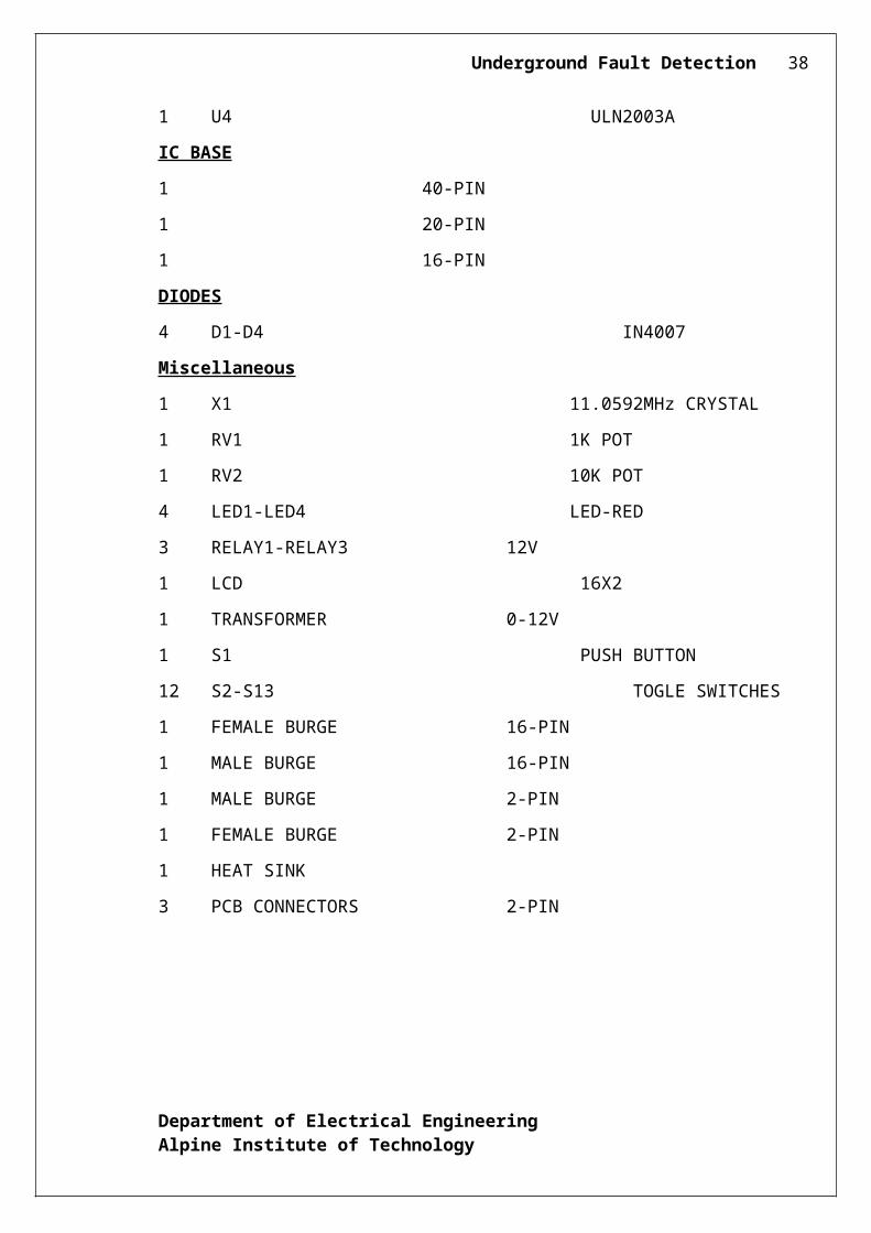
1 U4 ULN2003A
IC BASE
1 40-PIN
1 20-PIN
1 16-PIN
DIODES
4 D1-D4 IN4007
Miscellaneous
1 X1 11.0592MHz CRYSTAL
1 RV1 1K POT
1 RV2 10K POT
4 LED1-LED4 LED-RED
3 RELAY1-RELAY3 12V
1 LCD 16X2
1 TRANSFORMER 0-12V
Department of Electrical EngineeringAlpine Institute of Technology
Underground Fault Detection 31
1 S1 PUSH BUTTON
12 S2-S13 TOGLE SWITCHES
1 FEMALE BURGE 16-PIN
1 MALE BURGE 16-PIN
1 MALE BURGE 2-PIN
1 FEMALE BURGE 2-PIN
1 HEAT SINK
3 PCB CONNECTORS 2-PIN
9.CODING
Department of Electrical EngineeringAlpine Institute of Technology
Underground Fault Detection 32
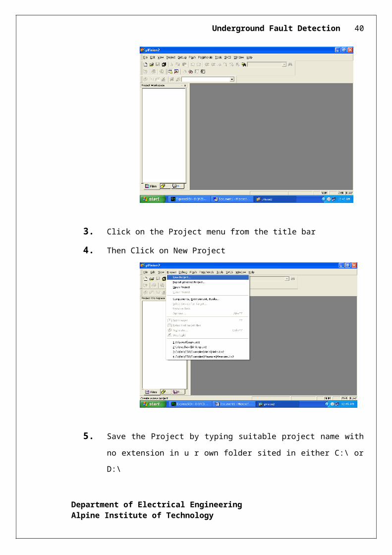
9.1 COMPILER
1. Click on the Keil Vision Icon on Desktop
2. The following fig will appear
3. Click on the Project menu from the title bar
4. Then Click on New Project
Department of Electrical EngineeringAlpine Institute of Technology
Underground Fault Detection 33
5. Save the Project by typing suitable project name with no extension in u r own
folder sited in either C:\ or D:\
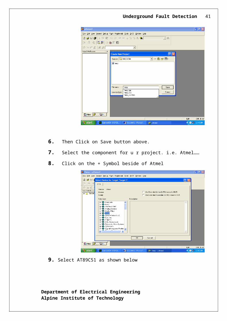
6. Then Click on Save button above.
7. Select the component for u r project. i.e. Atmel……
8. Click on the + Symbol beside of Atmel
9. Select AT89C51 as shown below
Department of Electrical EngineeringAlpine Institute of Technology
Underground Fault Detection 34
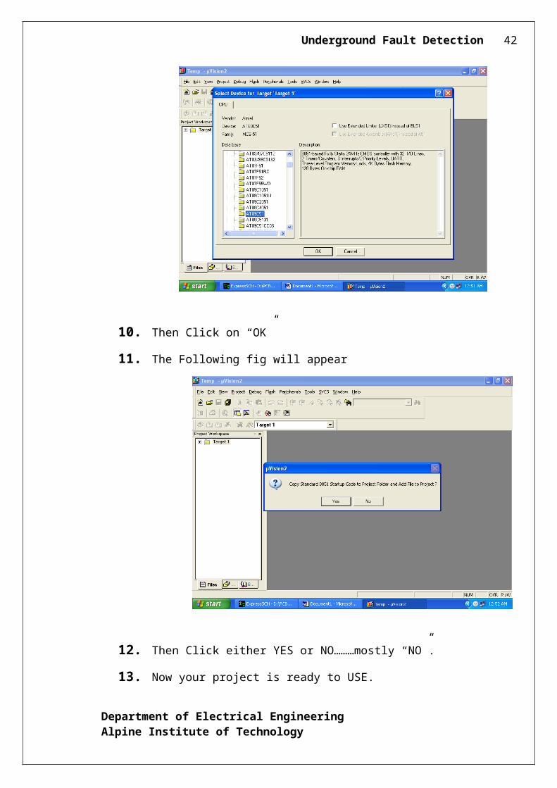
10. Then Click on “OK”
11. The Following fig will appear
12. Then Click either YES or NO………mostly “NO”.
13. Now your project is ready to USE.
Department of Electrical EngineeringAlpine Institute of Technology
Underground Fault Detection 35
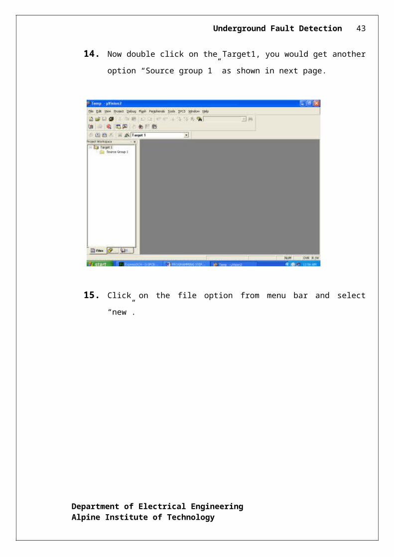
14. Now double click on the Target1, you would get another option “Source group
1” as shown in next page.
15. Click on the file option from menu bar and select “new”.
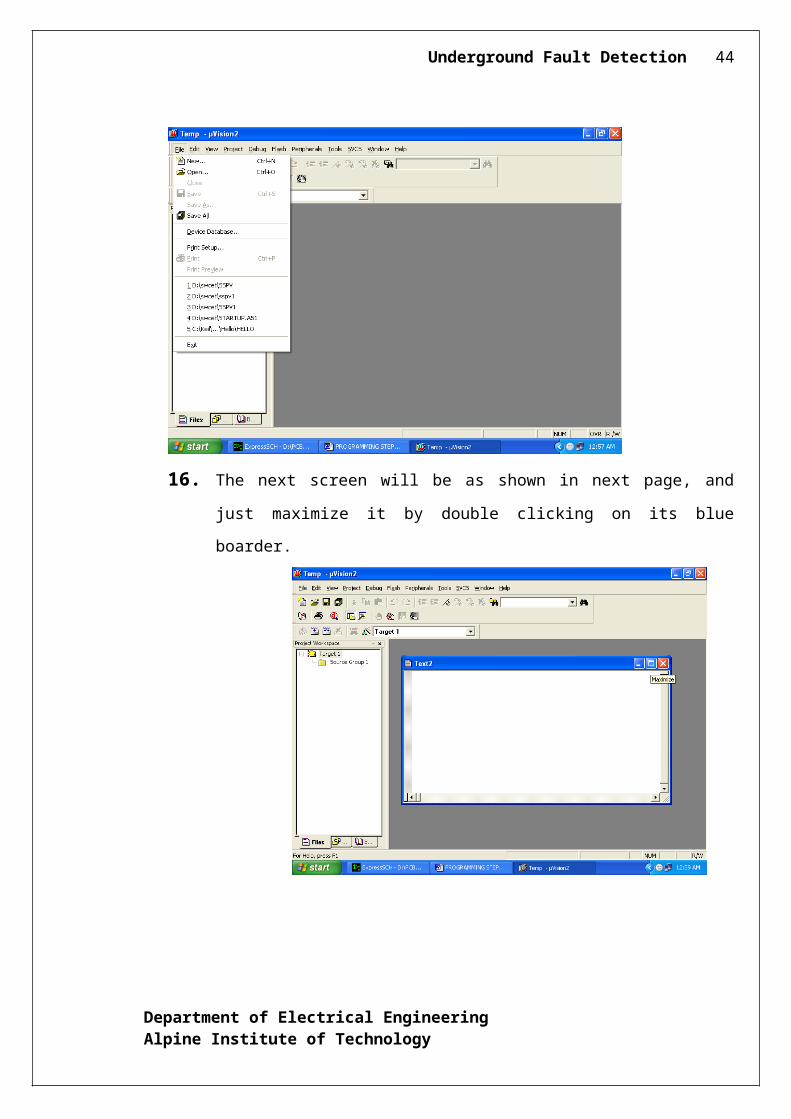
16. The next screen will be as shown in next page, and just maximize it by double
clicking on its blue boarder.
Department of Electrical EngineeringAlpine Institute of Technology
Underground Fault Detection 36
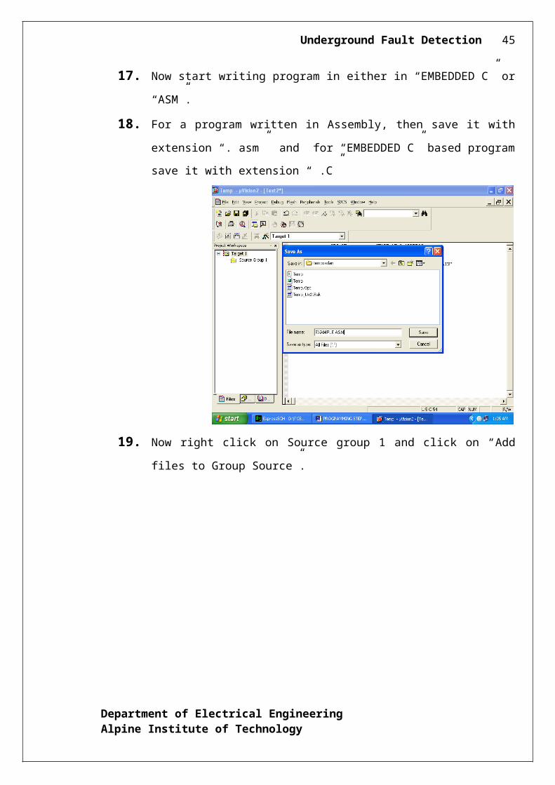
17. Now start writing program in either in “EMBEDDED C” or “ASM”.
18. For a program written in Assembly, then save it with extension “. asm” and for
“EMBEDDED C” based program save it with extension “ .C”
19. Now right click on Source group 1 and click on “Add files to Group Source”.
Department of Electrical EngineeringAlpine Institute of Technology
Underground Fault Detection 37
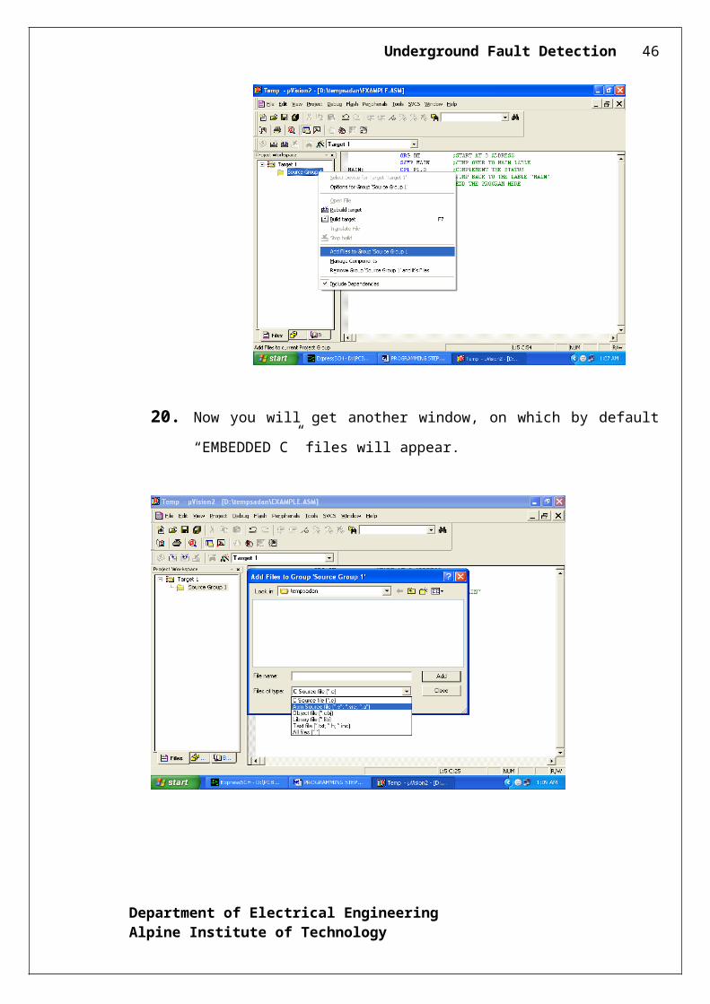
20. Now you will get another window, on which by default “EMBEDDED C” files
will appear.
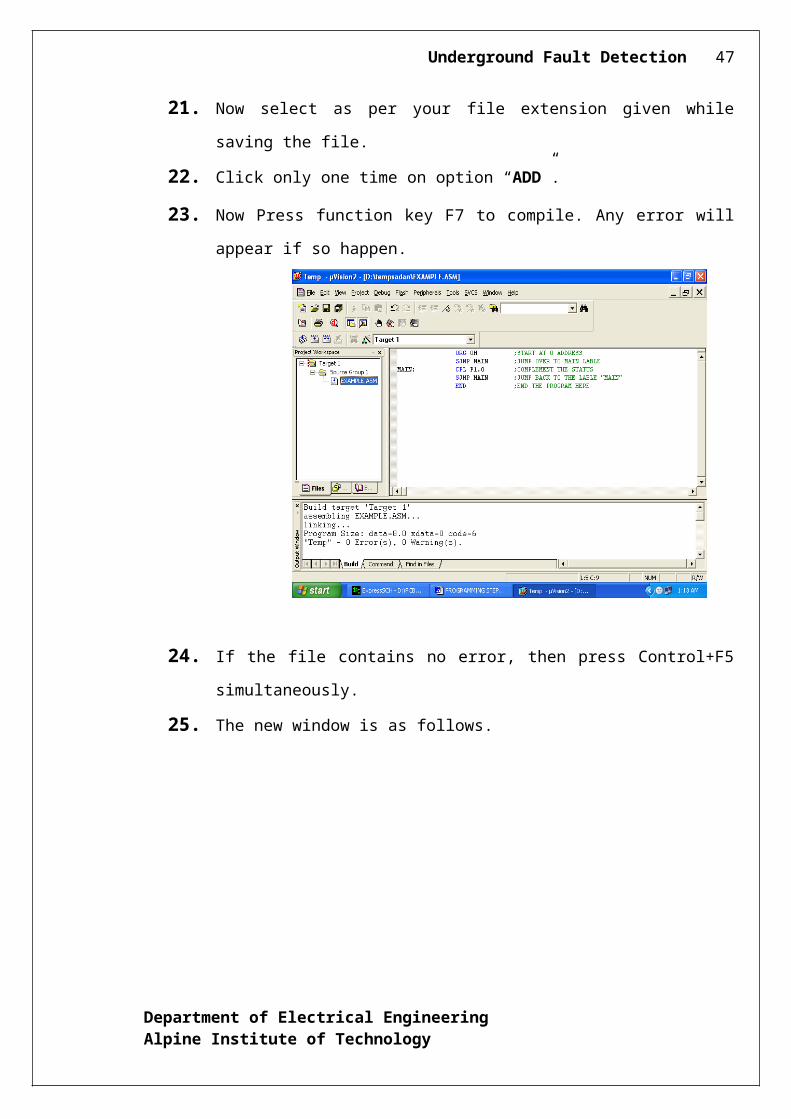
21. Now select as per your file extension given while saving the file.
22. Click only one time on option “ADD”.
23. Now Press function key F7 to compile. Any error will appear if so happen.
Department of Electrical EngineeringAlpine Institute of Technology
Underground Fault Detection 38
24. If the file contains no error, then press Control+F5 simultaneously.
25. The new window is as follows.
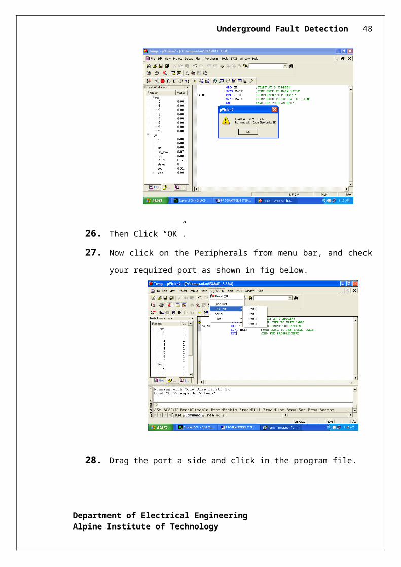
26. Then Click “OK”.
27. Now click on the Peripherals from menu bar, and check your required port as
shown in fig below.
Department of Electrical EngineeringAlpine Institute of Technology
Underground Fault Detection 39
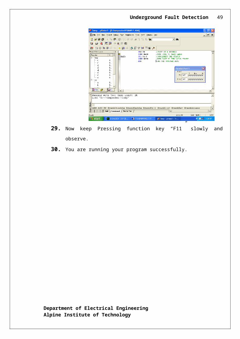
28. Drag the port a side and click in the program file.
29. Now keep Pressing function key “F11” slowly and observe.
30. You are running your program successfully.
Department of Electrical EngineeringAlpine Institute of Technology
Underground Fault Detection 40
9.2 SOURCE CODE
#include<at89x52.h>
#define LCDDATA P2#define ADCDATA P1#define MINIMUM 5
sbit BUSY = P2^7;sbit RS = P2^0;sbit RW = P2^1;sbit EN = P2^2;
sbit OE = P1^3; //RD pinsbit SC = P1^4; // WR is active LOW pinsbit EOC = P1^5; //INTR is active LOW pin
sbit RELAY1 = P1^0;sbit RELAY2 = P1^1;sbit RELAY3 = P1^2;
unsigned char Buff[3] = 0;
void ISR_T0() interrupt 1{
TH0 = 0x4B;
Department of Electrical EngineeringAlpine Institute of Technology
Underground Fault Detection 41
TL0 = 0xFF;
TF0 = 0;}
void Delay(unsigned int time){ unsigned int i = 0;
for(i=0;i<time;i++);}
unsigned char Read_ADC(){ unsigned char temp = 0;
SC = 1; // Make WR pin lowDelay(150); // wait for a whileSC = 0; // Make WR pin Highwhile(EOC == 1); // wait till INTR pin goes lowwhile(EOC == 0); // wait till INTR pin goes HighDelay(150);OE = 0; // Make RD pin LOWtemp = ADCDATA;OE = 1; // MAKE RD Pin HIGHreturn temp;
}
/*Function to check status of LCD*/void BusyCheck(){
BUSY = 1;RS = 0; // RS =0 FOR COMMANDRW = 1; // RW = 1 FOR READINGwhile(BUSY){
EN = 0; // ENABL EIS LOWEN = 1; // ENABLE IS HIGH
}}
/*Function to Send Command to LCD*/void LCDCMD(unsigned char CMD)
Department of Electrical EngineeringAlpine Institute of Technology
Underground Fault Detection 42
{BusyCheck();LCDDATA = CMD;RS = 0; // RS =0 FOR COMMANDRW = 0; // RW = 0 FOR WRITINGEN = 1; // ENABLE IS HIGHEN = 0; // ENABL EIS LOW
}
/*Function to Send Data to LCD*/void LCDData(unsigned char Data){
BusyCheck();LCDDATA = Data;RS = 1; // RS =1 FOR DATARW = 0; // RW = 0 FOR WRITINGEN = 1; // ENABLE IS HIGHEN = 0; // ENABL EIS LOW
}
void LCDString(unsigned char *str){
while(*str){
LCDData(*str);str++;
}
}
void Init_T0(){
TMOD = 0x01; // SET THE TIMER0 IN MODE 1 MODETH0 = 0x4B; // LOAD THE TH0 VALUETL0 = 0xFF; // LOAD THE TL0 VALUEET0 = 1; // ENABLE THE TIMER0 INTERRUPTEA = 1; // ENABLE ALL INTERRUPTTR0 = 1; // START THE TIMER
}
/*Function to Initalize LCD*/void Init_LCD(){
/*Command to Select 2 line , 5x7 matrix mode of LCD */
Department of Electrical EngineeringAlpine Institute of Technology
Underground Fault Detection 43
LCDCMD(0x38);
/*Command to shift the cursor to next position when Data is send in LCD */LCDCMD(0x06);
/*Command to ON Display, OFF the Cursor in LCD */LCDCMD(0x0C);
/*Return cursor home */LCDCMD(0x02);
}
void Display(unsigned char Data){
switch(Data){
case 170:LCDString("1KM");
break;case 204:
LCDString("2KM"); break;
case 219:LCDString("3KM");
break;case 227:
LCDString("4KM"); break;
case 255:LCDString("NF ");
break;default:
break;}
}
void main(){ P0 = 0x0F;
Buff[0] = 0xFF;Init_T0();Init_LCD();
while(1){
P0 = 0x01;
Department of Electrical EngineeringAlpine Institute of Technology
Underground Fault Detection 44
LCDCMD(0x80);LCDString("Status : Healthy ");Display(Read_ADC());LCDCMD(0x87);LCDString("Fault : None: ");Display(Read_ADC());
LCDCMD(0xC0);
Display(Read_ADC());
P0 = 0x04;LCDCMD(0x80);LCDString("Status : Faulty ");Display(Read_ADC());LCDCMD(0x87);LCDString("Fault at 5.0km");Display(Read_ADC());
P0=0x05LCDCMD(0x80);LCDString("Status : Faulty ");Display(Read_ADC());LCDCMD(0x87);LCDString("Fault at 10 km: ");Display(Read_ADC());
P0=0x06LCDCMD(0x80);LCDString("Status :Faulty ");Display(Read_ADC());LCDCMD(0x87);LCDString("Fault at 15 km");Display(Read_ADC());
P0=0x07LCDCMD(0x80);LCDString("Status : Faulty ");Display(Read_ADC());LCDCMD(0x87);LCDString("Fault at 20km ");Display(Read_ADC());
}}
Department of Electrical EngineeringAlpine Institute of Technology
Underground Fault Detection 45
10. HARDWARE TESTING
10.1 CONTINUITY TEST:In electronics, a continuity test is the checking of an electric circuit to see if current
flows (that it is in fact a complete circuit). A continuity test is performed by placing a small
voltage (wired in series with an LED or noise-producing component such as a piezoelectric
speaker) across the chosen path. If electron flow is inhibited by broken conductors,
damaged components, or excessive resistance, the circuit is "open".
Devices that can be used to perform continuity tests include multi meters which
measure current and specialized continuity testers which are cheaper, more basic devices,
generally with a simple light bulb that lights up when current flows.
An important application is the continuity test of a bundle of wires so as to find the two
ends belonging to a particular one of these wires; there will be a negligible resistance
between the "right" ends, and only between the "right" ends.
This test is the performed just after the hardware soldering and configuration has
been completed. This test aims at finding any electrical open paths in the circuit after the
soldering. Many a times, the electrical continuity in the circuit is lost due to improper
soldering, wrong and rough handling of the PCB, improper usage of the soldering iron,
component failures and presence of bugs in the circuit diagram. We use a multi meter to
perform this test. We keep the multi meter in buzzer mode and connect the ground terminal
of the multi meter to the ground. We connect both the terminals across the path that needs to
be checked. If there is continuation then you will hear the beep sound.
Department of Electrical EngineeringAlpine Institute of Technology
Underground Fault Detection 46
10.2 POWER ON TEST:
This test is performed to check whether the voltage at different terminals is
according to the requirement or not. We take a multi meter and put it in voltage mode.
Remember that this test is performed without microcontroller. Firstly, we check the output
of the transformer, whether we get the required 12 v AC voltage.
Then we apply this voltage to the power supply circuit. Note that we do this test
without microcontroller because if there is any excessive voltage, this may lead to damaging
the controller. We check for the input to the voltage regulator i.e., are we getting an input of
12v and an output of 5v. This 5v output is given to the microcontrollers’ 40 th pin. Hence we
check for the voltage level at 40th pin. Similarly, we check for the other terminals for the
required voltage. In this way we can assure that the voltage at all the terminals is as per the
requirement.
Department of Electrical EngineeringAlpine Institute of Technology
Underground Fault Detection 47
11. RESULTS
Department of Electrical EngineeringAlpine Institute of Technology
Underground Fault Detection 48
12. CONCLUSION
Department of Electrical EngineeringAlpine Institute of Technology
Underground Fault Detection 49
13. BIBLIOGRAPHY
TEXT BOOKS REFERED:
1. “The 8051 Microcontroller and Embedded systems” by Muhammad Ali Mazidi and
Janice Gillispie Mazidi , Pearson Education.
2. ATMEL 89S52 Data Sheets.
WEBSITES
www.atmel.com
www.beyondlogic.org
www.wikipedia.org
www.howstuffworks.com
www.alldatasheets.com
Department of Electrical EngineeringAlpine Institute of Technology