underground design forsmark, layout d2 – grouting
TRANSCRIPT
Svensk Kärnbränslehantering ABSwedish Nuclear Fueland Waste Management Co
Box 3091, SE-169 03 Solna Phone +46 8 459 84 00
R-08-114
Underground Design Forsmark, Layout D2Grouting
Martin Brantberger, Ramböll
Thomas Janson, Tyréns AB
July 2009

Underground Design Forsmark, Layout D2
Grouting
Martin Brantberger, Ramböll
Thomas Janson, Tyréns AB
July 2009
Updated 2019-10
ISSN 1402-3091
SKB Rapport R-08-114
This report concerns a study which was conducted for SKB. The conclusions and viewpoints presented in the report are those of the authors and do not necessarily coincide with those of the client.
A pdf version of this document can be downloaded from www.skb.se.

The original report, dated July 2009, was found to contain editorial errors which have been corrected in this updated version.

3
Summary
Restrictions must be observed with regard to permitted inflow of water in different functional areas in connection with the construction of the underground facility of the final repository. To ensure that permitted seepage is not exceeded it may be necessary to carry out sealing by grouting measures.
The purpose of the grouting design work is to show that stated restrictions with regard to seepage in the underground facility can be achieved by grouting. This is to be done by:
• Showing that technique is available which, in anticipated conditions at the relevant site, can satisfy stipulated requirements.
• Estimating the amounts of grout and other resources that are needed.
It has been evaluated that the greatest inflow of water can be anticipated in the ramp and shafts at the depth 0–100 m. The inflow of water decreases at greater depth and the need of grouting measures decreases accordingly. At depths greater than 200 m only minor inflow is anticipated on passing deformation zones. It is likely that no grouting at all will be required along long sections at greater depth than 200 m. However extensive grouting can be anticipated when passing deformation zones in deposition tunnels because of the extraordinary requirement on maximum acceptable leakage.
From the calculations of inflow before grouting, experience of performed grouting and assessment of the sealing effect and hydraulic aperture, the following grouting strategy has been chosen:
• Test drilling and grouting trials should be made from surface level as regards grouting of upper parts of ramp and shafts.
• Large-scale curtain grouting is to be carried out from surface level around all access parts.
• Niches in the ramp are to be used for grouting in stages about 100 m long around the drilled shafts.
• The skip shaft is grouted mainly from the face of the excavation.
• Grouting of different functional areas under the depth 200 m is made as a selective pre-grouting. However, systematic pre-grouting can be expected when passing deformation zones at depths below 200 m.
• Cement-based grouts are to be used if possible. It is suggested that silica sol could be used as a complement if a second round of pre-grouting is needed and for post-grouting of point leakage. In deposition tunnels, with high requirements on water tigthness, a new grouting concept with silica sol and cement will be needed from the start of the first round of pre-grouting.
• Preparedness for rapid hardening grout is to be available as well as alternative sealing methods when excavating ramp and shafts.
The table below presents a summary of amounts of grout for the different functional areas. Large amounts of grout can be anticipated in the ramp and the shafts in the upper 200 metres. The difference between estimated maximum and minimum amounts is however considerable. This reflects the uncertainty about the conditions that will be met in tunnel excavation and grouting.
It is concluded that grouting in Forsmark will for most of the facilities be able to fulfil the prescribed requirements on water leakage. Grouting will in some cases be difficult to perform, and in the most unfavourable conditions there is a risk that the tightness requirement will not be fulfilled in certain areas.
The grouting measures described are considered realistic although some methods involve relatively unproven techniques, as for example silica sol and other less proven and documented methods such as grouting in deep boreholes.

4
Functional areas/underground openings Volume of grout Min./type/max. (m3)
Accesses, incl. exhaust shaft SA01 and SA02 (0 to –200m)Ramp and Shafts (6 pcs) 590–2,350 (Kmin)
970–3,830 (Ktyp)1,460–5,840 (Kmax)
Central area (–470m)Rock caverns (grouting in deformation zones) – (Kmin)
20–60 (Ktyp)30–140 (Kmax)
Deposition area (–470m)Deposition, transport and main tunnels (grouting in deformation zones)
– (Kmin)475–1,890 (Ktyp)1,040–4,100 (Kmax)

5
Sammanfattning
Vid byggandet av slutförvarets undermarksanläggning måste restriktioner avseende tillåtet vatten-inläckage till olika anläggningsdelar beaktas. För att säkerställa att tillåtet inläckage ej överskrids kan tätning genom injektering behöva utföras.
Syftet med projekteringen avseende injekteringsarbetena är att visa att angivna restriktioner avseende inläckage för undermarksanläggningen kan uppfyllas genom injektering. Detta ska göras genom att:
• Visa att teknik finns som, vid förväntade förhållanden på den aktuella platsen, kan uppfylla ställda krav.
• Bedöma vilka mängder av injekteringsmedel och andra resurser som behövs.
Det har konstaterats att det största vatteninläckaget kan förväntas i ramp och schakt på djupet 0–100 m. På större djup minskar vatteninläckaget. På djup större än 200 m förväntas endast mindre inläckage och då i huvudsak vid passage av deformationszoner. Det är troligt att ingen injektering behöver utföras över längre tunnelsträckor på djupet under 200 m. Dock kan omfattande injektering bli nödvändigt vid passager av deformationszoner. Detta kan speciellt förväntas i deponeringstunnlar, vid passage av deformationszoner, på grund av de höga kraven där.
Från beräkningar av inflöde före injektering, tidigare injekteringserfarenheter, bedömning av svårighetsgrad och hydrauliska sprickvidden har följande övergripande principer formulerats:
• Provborrning och injekteringsförsök från markytan utförs inför injektering av ramp och schakt.
• Storskalig ridåinjektering utförs från markytan kring samtliga tillfartsdelar.
• Nischer i rampen används för injektering i ca 100 m långa etapper runt de borrade schakten.
• Sänkschakt injekteras huvudsakligen från schaktbotten.
• Injektering av anläggningsdelar under djupet 200 m görs som en selektivt förinjektering, dock kan systematisk förinjektering förväntas vid passsage av deformationszoner under djupet 200 m.
• Injektering med cementbaserade injekteringsmedel ska i huvudsak användas. Silica sol används vid behov av en andra omgång förinjektering, förutom i deponeringstunnlar, samt vid efterinjektering av punktläckage. I deponeringstunnlar, med högre inläckagekrav jämfört mot övriga anläggningsdelar, skall ett koncept med silica sol och cement användas i första omgångens förinjektering.
• Beredskap för snabbhärdande injekteringsmedel skall finnas samt alternativa tätningsmetoder vid drivning av ramp och schakt.
I tabellen nedan sammanfattas de uppskattade injekteringsmängder för de olika anläggningsdelarna. Stora mängder injekteringsbruk kan förväntas i rampen och schakten de övre 200 metrarna. Skillnaden mellan beräknade max – och mininmängder är dock stor. Detta speglar osäkerheten om vilka förhållanden som kommer att påträffas vid tunneldrivningen och injekteringen.
Det har antagits att injektering är möjligt att utföra i Forsmark så att ställda krav på täthet uppfylls i större delen av anläggningen. Injekteringsarbetet blir i vissa fall svårt och vid de mest ogynnsamma förhållandena finns en risk att täthetskravet inte uppfylls för vissa utrymmen.
Det beskrivna injekteringsutförandet kan anses realistiskt trots att vissa injekteringsmetoder innebär relativt obeprövad teknik. Till exempel är injektering med silica sol mindre beprövat och dokumenterat liksom metoder med injektering i djupa borrhål.

6
Anläggningsdel/undermarksanläggning Injekteringsmängd Min./typ/max. (m3)
Nedfarter, inkl frånluftschakt (0 to –200m)Ramp och schakt (4 st) 590–2 350 (Kmin)
970–3 830 (Ktyp)1 460–5 840 (Kmax)
Central område (–470m)Berghallar (injektering i deformationszoner) – (Kmin)
20–60 (Ktyp)30–140 (Kmax)
Deponeringsområde (–470m)Deponering- transport- och stamtunnlar (injektering i deformationszoner)
– (Kmin)475–1 890 (Ktyp)1040–4 100 (Kmax)
7
Contents
1 Introduction 91.1 Background 91.2 Purpose 91.3 Implementation 91.4 Nonconformities to the design premises 101.5 Terminology 11
2 Premises 132.1 Geology and hydrogeology 132.2 The final repository facility 162.3 Requirements on grouting 17
3 Assessment of water ingress before grouting 193.1 Introduction 193.2 Calculation methodology 193.3 Input data and assumptions 21
3.3.1 Hydraulic characteristics 213.3.2 Other input data and assumptions 23
3.4 Calculation result 233.5 Conclusions 26
4 Basis of grouting measures 274.1 Introduction 274.2 Summary of grouting experience 274.3 Assessing the degree of difficulty for grouting 284.4 Calculation of fracture apertures 33
5 Grouting measures 375.1 Strategy for establishing grouting measures 375.2 General principles 37
5.2.1 Grouting types 375.2.2 Grouts 385.2.3 Grouting fan 385.2.4 Execution and equipment 38
5.3 Choice of preliminary grouting measures in different functional areas 395.3.1 Summary of preliminary grouting measures 395.3.2 Accesses 405.3.3 Central area 435.3.4 Deposition area 43
5.4 Choice of grouting measures during construction 445.5 Checks 44
5.5.1 General 445.5.2 Checks before grouting 465.5.3 Checks during grouting 465.5.4 Checks after grouting, before rock excavation 465.5.5 Checks after grouting, after rock excavation 46
5.6 Specific of grouting measures for different grouting types, GrT 475.6.1 Grouting type 1 475.6.2 Grouting type 2 485.6.3 Grouting type 3 49
5.7 Curtain grouting 525.8 Post-grouting 52

8
6 System behaviour 556.1 Introduction 556.2 Calculation methods 556.3 Calculation result 556.4 Comparison between calculation results and experienceof grouting 556.5 Conclusions 57
7 Compilation of materials and other resources 597.1 Introduction 597.2 Amounts of grout 59
7.2.1 Calculation methods 597.2.2 Input data and assumptions 607.2.3 Calculation results 617.2.4 Comparison between calculated amounts and experience of grouting 647.2.5 Conclusions 65
7.3 Equipment summary 65
8 Overall judgement of feasibility and uncertainty 678.1 General 678.2 Grouting measures 678.3 Calculations 70
9 Continued design 71
10 References 73
Appendix A Experience of grouting 75References 85Appendix B Input data for calculating inflow of water 87Appendix C Grout recipes 89

9
1 Introduction
1.1 BackgroundRestrictions must be observed with regard to permitted inflow of water in different functional areas in connection with the construction of the underground facility of the final repository. To ensure that permitted seepage is not exceeded it may be necessary to carry out sealing by grouting measures. The requirements have been given concrete form in the Underground Design Premises/D2 (UDP) /SKB 2007/, eg, requirements on maximum permitted inflow to different underground openings and also requirements on composition of the grout.
Design has been carried out with regard to grouting based on design premises in UDP /SKB 2007/ and engineering descriptions of the rock mass presented in Site Engineering Report, Guidelines for underground design step D2 (SER) /SKB 2008a/.
1.2 PurposeThe purpose of the grouting design work is according to UDP /SKB 2007/ to show that stated restrictions with regard to seepage in the underground facility can be achieved by grouting. This is to be done according to UDP /SKB 2007/ by:• Showing that technique is available which, in anticipated conditions at the relevant site, can satisfy
stipulated requirements.• Estimating the amounts of grout and other resources that are needed.
1.3 ImplementationAn overall description of the design methodology is given in UDP /SKB 2007/. For the grouting design work the following design activities are to be carried out according to UDP /SKB 2007/:• Assessment of “ground behaviour”.• Configuration of grouting methodology.• Assessment of “system behaviour”.• Assessment of amounts and other resources.• Assessment of feasibility and uncertainties.
Chapter 2 presents, by way of introduction, the premises for the grouting design work concerning geology and hydrogeology, the underground facility and grouting measures.
In the assessment of “ground behaviour” the probable inflow of water to the different functional areas before grouting is presented (see Chapter 3).
A large number of grouting works have been studied to obtain a basis for the configuration of grouting measures. These are presented in Appendix A.
The configuration of grouting measures refers to a specification of how the grouting is to be performed on the basis of “grouting types” (see Chapter 5). The criteria for evaluation of the feasibility of the proposed grouting measures, based on recommendations in /Emmelin et al. 2007/, are the following:• The grouting measures are to be realistic in relation to present know-how and experience.• The grouting measures are to be robust in relation to anticipated variations in characteristics of
the rock mass.• A process for handling prevailing uncertainties should be presented.• Assessments of amounts, time needed and cost and also that these may not be unreasonably large.
10
In the assessment of “system behaviour” the probable inflow of water to the different parts of the facility after grouting is presented (see Chapter 6).
The assessment of amounts and other resources concern grout, total length of boreholes and also the need of equipment for special grouting measures (see Chapter 7).
In the assessment of feasibility and uncertainties a feedback has been made to the purpose of the design (see Chapter 8). The assessment of feasibility and uncertainties also constitute a basis for the technical risk assessment, which is made as a separate activity in design step D2 according to /SKB 2007/.
For the design in step D2 the application of the observational method implies, according to UDP /SKB 2007/, that the following is to be carried out:
• Acceptable behaviour for the construction is to be stated.
• Possible behaviour is to be assessed.
• Extent and which parameters that should be measured and checked in the construction stage are to be stated.
What is acceptable behaviour with regard to grouting is stated by SKB in the form of requirements on maximum permitted inflow of water to various underground openings. Accordingly, maximum permitted inflow to the various underground openings is one of the design premises, as presented in Chapter 2.
Possible behaviour is judged as the amount of water inflow to various underground openings before grouting, i.e. “ground behaviour”, and after grouting, i.e. “system behaviour”. These assessments are presented in Chapter 3 and Chapter 6 respectively.
Extent of parameters that should be measured and checked in the construction stage are presented in Chapter 5.5.
As agreed with SKB alternatives to grouting in order to mitigate environmental effects due to ground water table drawdown have not been included in the study, and will instead be conducted in a separate evaluation.
Nonconformities to UDP /SKB 2007/ have been agreed with SKB in connection with the design. These nonconformities are presented broadly in Chapter 1.4.
1.4 Nonconformities to the design premisesAccording to UDP /SKB 2007/ the rock mass is to be divided into “ground types”, giving a general description of the rock mass and also the values of a number of parameters with regard to rock mechanics and hydrogeology. It has been decided that “ground types” are not to be applied in the assessment of water inflow and the configuration of grouting methods, which was the instruction in UDP /SKB 2007/. The reason for this was that the hydrogeological description of “ground types” was not deemed suitable for use together with the other hydrogeological description in SER /SKB 2008a/. Nonconformities to the UDP /SKB 2007/ with regard to the above are described in the respective chapter of this report.
Geometries and relative location of the functional areas, especially the central area, are taken from the UDP /SKB 2007/ without consideration to later adjustments. The reason why such adjustments have not been observed is partly because they lack traceable reference, and partly because they lack significance for result and conclusions.

11
1.5 TerminologySome of the terms and concepts used in this report are explained below. The list comprises terms and concepts that are specific for SKB, for grouting, the rock construction process, or for other reasons need to be explained or defined in order to describe the discussed concepts in a stringent way. The terms used in this report are noted in Table 1-1.
Table 1-1. Terminology.
Term Explanation Reference
SER “Site Engineering Report, Guidelines for underground design step D2” /SKB 2008a/. A report that presents an engineering description of the rock mass for design step D2.
UDP “Underground design premises/D2” /SKB 2007/. A steering document for rock engineering design work in step D2.
Functional area Part of underground facility of the final repository. Divided into repository access, central area and deposition area
/SKB 2008a/
Repository access Functional area including access ramp and shafts to central area /SKB 2008a/Central area Functional area including rock caverns and tunnels for personnel,
operation and maintenance/SKB 2008a/
Deformation zone Deformation zone is a general term that refers to an essentially 2D structure along which there is a concentration of brittle, ductile or combined brittle and ductile deformation. Deformation zones at Forsmark are denoted ZFM followed by two to eight letters or digits. An indication of the orientation of the zone is included in the identification code.
/SKB 2008a/
Deposition area Functional area for canister deposition including deposition tunnels, main tunnels and deposition holes
/SKB 2008a/
Fracture domain A fracture domain is a rock volume outside deformation zones in which rock units show similar fracture frequency characteristics. Fracture domains at Forsmark are denoted FFMxx.
/SKB 2008a/
Fracture zone Fracture zone is a term used to denote a brittle deformation zone without any specification whether there has or has not been a shear sense of movement along the zone.
/SKB 2008a/
Grouting type Description of principles with regard to extent and execution of pre-grouting
/SKB 2008a/
Rock domain A rock domain refers to a rock volume in which rock units that show specifically similar composition, grain size, degree of bedrock homogeneity, and degree and style of ductile deformation have been combined and distinguished from each other. Different rock domains at Forsmark are referred to as RFMxxx.
/SKB 2008a/
Rock unit A rock unit is defined on the basis of the composition, grain size and inferred relative age of the dominant rock type. Other geological features including the degree of bedrock homogeneity, the degree and style of ductile deformation, the occurrence of early-stage alteration (albitisation) that affects the composition of the rock, and anomalous fracture frequency also help define and distinguish some rock units.
/SKB 2008a/
Systematic pre-grouting Several successive planned full grouting fansSelective pre-grouting Grouting of a number of boreholes or a full grouting fan, that is
made after assessment on site of investigation holes or probing holes.
Underground opening The underground openings required to accomodate the sub-surface facilities.– The actual location and geometry of the underground openings.– The rock surrounding the openings affected by the rock civil works.– Civil works and stray materials remaining when the underground openings are backfilled.
/SKB 2007/

13
2 Premises
2.1 Geology and hydrogeologyAccording to SER /SKB 2008a/ the rock volume for the underground facility is comprised within a relatively homogenous tectonic lens. This part of the tectonic lens is divided in two rock domains, RFM029 and RFM045. The rock domains RFM029 and RFM045 consist mainly of a medium-grained metagranite and an albitised metagranite, respectively. Both of the rock domains include a greater or smaller element of metagranodiorite, granite, amphibolite and pegmatite.
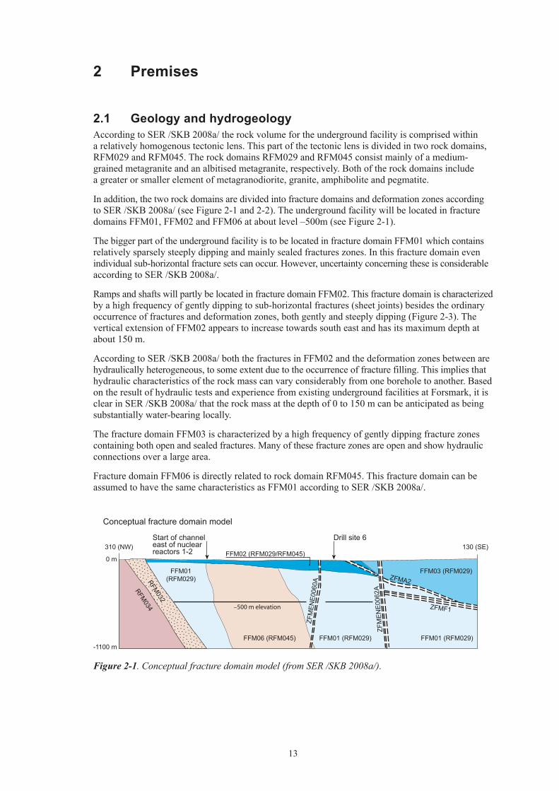
In addition, the two rock domains are divided into fracture domains and deformation zones according to SER /SKB 2008a/ (see Figure 2-1 and 2-2). The underground facility will be located in fracture domains FFM01, FFM02 and FFM06 at about level –500m (see Figure 2-1).
The bigger part of the underground facility is to be located in fracture domain FFM01 which contains relatively sparsely steeply dipping and mainly sealed fractures zones. In this fracture domain even individual sub-horizontal fracture sets can occur. However, uncertainty concerning these is considerable according to SER /SKB 2008a/.
Ramps and shafts will partly be located in fracture domain FFM02. This fracture domain is characterized by a high frequency of gently dipping to sub-horizontal fractures (sheet joints) besides the ordinary occurrence of fractures and deformation zones, both gently and steeply dipping (Figure 2-3). The vertical extension of FFM02 appears to increase towards south east and has its maximum depth at about 150 m.
According to SER /SKB 2008a/ both the fractures in FFM02 and the deformation zones between are hydraulically heterogeneous, to some extent due to the occurrence of fracture filling. This implies that hydraulic characteristics of the rock mass can vary considerably from one borehole to another. Based on the result of hydraulic tests and experience from existing underground facilities at Forsmark, it is clear in SER /SKB 2008a/ that the rock mass at the depth of 0 to 150 m can be anticipated as being substantially water-bearing locally.
The fracture domain FFM03 is characterized by a high frequency of gently dipping fracture zones containing both open and sealed fractures. Many of these fracture zones are open and show hydraulic connections over a large area.
Fracture domain FFM06 is directly related to rock domain RFM045. This fracture domain can be assumed to have the same characteristics as FFM01 according to SER /SKB 2008a/.
Figure 2-1. Conceptual fracture domain model (from SER /SKB 2008a/).
(RFM029)
Conceptual fracture domain model
0 m
-1100 m
310 (NW) 130 (SE)Drill site 6Start of channel
east of nuclearreactors 1-2
RFM034
RFM032
FFM01
FFM02 (RFM029/RFM045)
FFM06 (RFM045) FFM01 (RFM029) FFM01 (RFM029)
FFM03 (RFM029)
–500 m elevation
ZFM
ENE0
060A
ZFM
ENE0
062A
ZFMF1
ZFMA2

14
Figure 2-2. Plan view of the rock domains, deformation zones and fracture domains at the Forsmark site at elevations, –150 m and –500 m, inside the target volume. The target volume denotes the rock volume that was selected during the site investigation process as potentially suitable for hosting a Final Repository Facility for spent nuclear fuel. In each figure, deformation zones marked in red are steeply dipping or vertical and have a trace length at the surface longer than 3,000 m. Zones marked in blue-green are steeply dipping or vertical and are less than 3,000 m in length. Zones marked in green are gently dipping. Other features are labelled directly on the figures (from /SKB 2008a/).
Elevation –150 m
Elevation –500 m

15
In the rock domains there are deformation zones of different length and width and also mechanic and hydraulic significance. The deformation zones are divided, according to their orientation and trace length at the surface into four main types /SKB 2008a/:
(1): vertical and steeply dipping zones with WNW and NW orientation consisting, mainly, of sealed fractures
(2): vertical and steeply dipping zones with ENE, NE and NNE orientation consisting of fractures and fracture groups
(3): Gently dipping zones with SE and S orientation consisting of open fractures containing crushed material
(4): vertical and steeply dipping zones with NNW orientation consisting, mainly, of sealed fractures
Figure 2-3. A: Cross-section illustration of the uppermost part of the bedrock. P = precipitation, E = evopotranspiration, R = Runoff (from /SKB 2008a/). B: Observed horizontal fractures in constructing the cooling water canal to the Forsmark nuclear power plant (from /Carlsson and Christiansson 2007/).
b
a
16
Deformation zones with trace length at the ground surface longer than 3 km require a respect distance between the deposition area and the zone, due the risk of seismicity caused by post-glacial rebound /SKB 2008a/. Deformation zones with shorter trace length than 3 km have no respect distance and are allowed to cross the deposition area, but no deposition holes are accepted inside these zones /Hansson et al. 2008/.
Hydraulic characteristics of the various fracture domains and deformation zones are presented in Chapter 3.3.1.
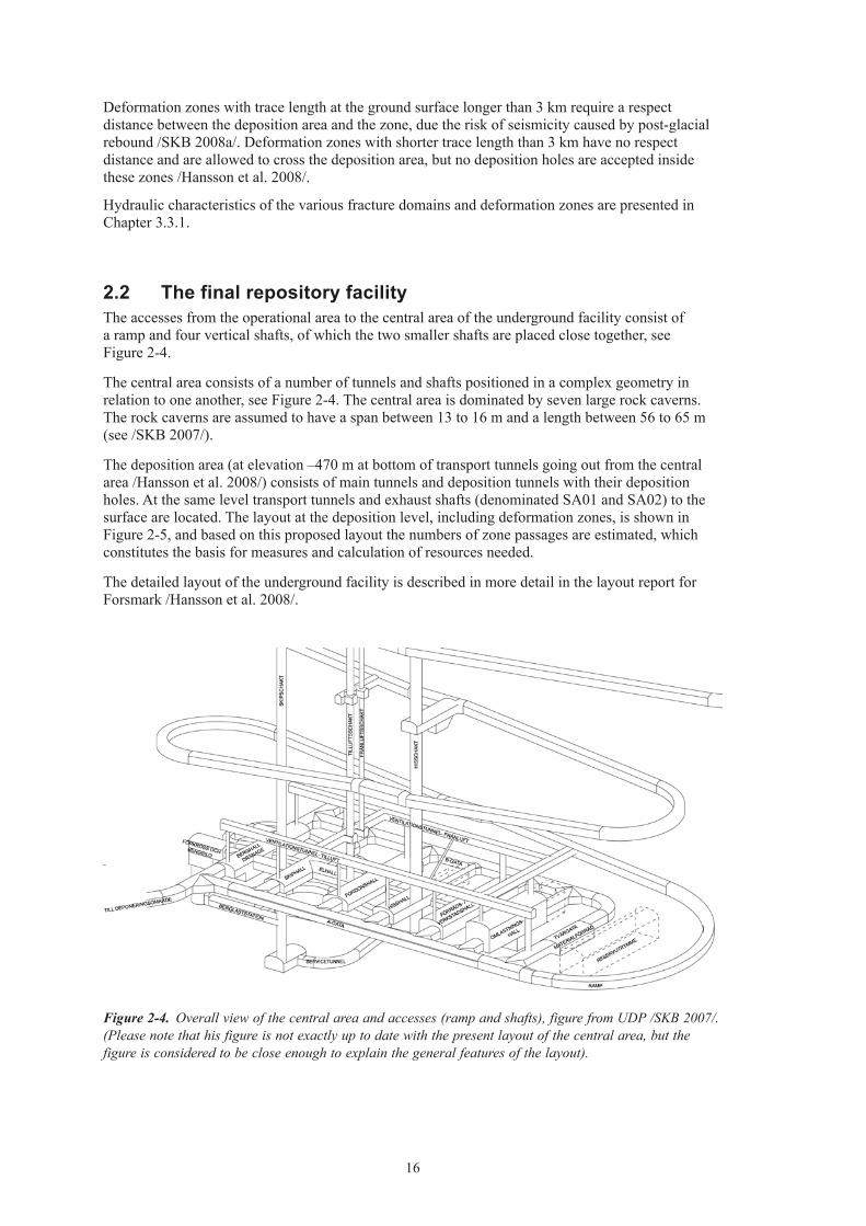
2.2 The final repository facilityThe accesses from the operational area to the central area of the underground facility consist of a ramp and four vertical shafts, of which the two smaller shafts are placed close together, see Figure 2-4.
The central area consists of a number of tunnels and shafts positioned in a complex geometry in relation to one another, see Figure 2-4. The central area is dominated by seven large rock caverns. The rock caverns are assumed to have a span between 13 to 16 m and a length between 56 to 65 m (see /SKB 2007/).
The deposition area (at elevation –470 m at bottom of transport tunnels going out from the central area /Hansson et al. 2008/) consists of main tunnels and deposition tunnels with their deposition holes. At the same level transport tunnels and exhaust shafts (denominated SA01 and SA02) to the surface are located. The layout at the deposition level, including deformation zones, is shown in Figure 2-5, and based on this proposed layout the numbers of zone passages are estimated, which constitutes the basis for measures and calculation of resources needed.
The detailed layout of the underground facility is described in more detail in the layout report for Forsmark /Hansson et al. 2008/.
Figure 2-4. Overall view of the central area and accesses (ramp and shafts), figure from UDP /SKB 2007/. (Please note that his figure is not exactly up to date with the present layout of the central area, but the figure is considered to be close enough to explain the general features of the layout).

17
2.3 Requirements on groutingThis section summarises the requirements and conditions used in assessing water inflow, configuration of grouting measures and also assessment of amounts.
• Premises according to UDP /SKB 2007/ are to be followed. According to UDP /SKB 2007/ the following conditions are to be observed in configuring the grouting methodology.
– SKB will present properties and recipes of currently available grouts and these grouts shall if possible be used. The need of other properties of the grout than those given by SKB shall however clearly be adressed. Recipes of grouts are presented in Appendix C.
– Existing techniques for the grouting measures are to be used.
– If otherwise equal methods are discussed, the method giving the lowest material use should be favoured provided that the objectives are fulfilled.
– Systematic pre-grouting should, if possible, be avoided in deposition tunnels.
– Boreholes may not be positioned so that they risk interfering with the locations of deposition holes. However, this requirement does not apply for grouting in deformation zones since no deposition holes will be permitted in such locations.
Figure 2-5. Layout at deposition level including deformation zones /Hansson et al. 2008/.
18
– According to UDP /SKB 2007/ the grouting measures are to be based on the estimated inflow of water before grouting (“ground behaviour”) and “grouting types” (GrT), which are stated in SER /SKB 2008a/. The following grouting types (GrT) are defined in SER as follows:
Grouting type 1 (GrT1): “Discrete fracture grouting”
Grouting type 2 (GrT2): “Systematic tunnel grouting”
Grouting type 3 (GrT3): “Control of large inflow and high-pressure”
According to UDP /SKB 2007/ a number of parameters are to be described for the respective grouting type. These are fan geometry, grout and also principle execution including pressure and controls. For GrT3, special execution and special equipment are also to be described if this is necessary. For more detailed description of grouting types, see Section 5.6.
• Requirements on grouting are stated in UDP /SKB 2007/.
– Acceptable inflow of water to the various underground openings in the underground facility: – Deposition holes: point leakage 0.1 l/min – Deposition tunnels: 1.7 l/min, 100 m; point leakage 1 l/min – Shaft and ramp: 10 l/min, 100 m – Other underground openings: 10 l/min, 100 m
– The requirements concerning maximal seepage per 100 m for different underground openings have been interpreted to mean that the requirements are to be fulfilled for the total length of the opening (for example tunnel). Based on rough estimates and experience from other grouting work it is considered improbable that the requirements can be fulfilled in a random stretch of 100 m. This is considered especially to be the case in ramps and shafts at a depth of 0–100 m and also in connection to certain deformation zones at the repository depth. For deposition tunnels the requirement has been interpreted as applying for each individual deposition tunnel.
– Cement-based grouts are to be used for “major fractures” and silica sol for “minor fractures”. In this case according to /Emmelin et al. 2007/ “major fractures” refer to fractures with a hydraulic fracture width ≥100 µm.
– The grout may not contain substances that could impair the barrier functions and pH is to be less than 11. This requirement has been dealt with in the design by suggesting only grouts that are provided by SKB. The composition of these grouting media has been tested within the framework of SKB’s present work of development.
– The technical life of deposition tunnels and deposition holes is 5 years. Corresponding time for other rock constructions is 100 years.
– Deposition holes are not to be sealed. This requirement has been observed in that deposition holes with point leakage > 0.1 l/min are rejected. Inflow of water to deposition holes shall according to UDP /SKB 2007/ be limited by choosing location of the hole in the rock.
• Hydrogeological characteristics according to SER /SKB 2008a/ are to be used.
• The basis for analyses and discussion is the current knowledge and competence concerning design and execution that is described in /Emmelin et al. 2007/.

19
3 Assessment of water ingress before grouting
3.1 IntroductionAccording to UDP /SKB 2007/ the inflow of water is to be calculated for different functional areas. The assessment of inflow is to be based both on the most probable conditions and on the most unfavourable conditions.
A deviation from UDP /SKB 2007/ is that no division into “ground types” has been made. Assessments of water inflow have instead been based on presentations of hydrogeological characteristics in SER /SKB 2008a/ for fracture domains at different depths and for deformation zones.
The assessment of water inflow has been made using analytical calculation methods. More detailed assessments of the water inflow are made within the framework of the site modelling.
3.2 Calculation methodologyAccording to /Bergman and Nord 1982/ the calculation of water inflow into a tunnel can be made using Equation 3-1 for the fracture domains and Equation 3-2 for the deformation zones. The equation applies both for a non-grouted and a grouted circular tunnel, but can also be used for rough calculations of other geometries.
3–1
3–2
in which
H = tunnel depth, below groundwater table (m)
K = representative hydraulic conductivity of the rock mass (m/s)
Kg = hydraulic conductivity of the grouted zone (m/s)
L = tunnel length (m)
T = transmissivity for deformation zone (m2/s)
t = thickness of grouted zone (m)
Qt = inflow in steady state conditions (m3/s)
rt = tunnel radius (m)
ξ = skin factor inside seal (dimensionless)
K = Kg is set for a non-grouted tunnel
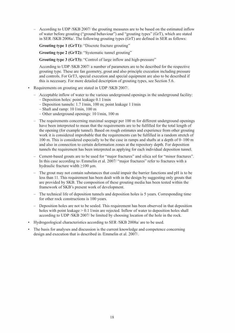
The significance of the different parameters in Equation 3-1 is presented in Figure 3–1.
ξ
π
+
+⋅
−+
⋅
⋅⋅⋅⋅=
tgt
t
rt
KK
rH
LHKQ1ln12ln
2
ξ
π
+
+⋅
−+
⋅
⋅⋅⋅=
tgt
t
rt
KK
rH
HTQ1ln12ln
2
20
Since the requirements in UDP /SKB 2007/, which are expressed per unit length for the different underground openings, the inflow in the fracture domain is calculated per 100 metre tunnel, i.e. the tunnel length (L) is set constant at 100 m in Equation 3-1.
The inflow to a shaft has been assessed with the aid of Equation 3-3. The equation was given as a basis in design step D1 /SKB 2004/.
3-3
For Equation 3-3 the following fringe conditions also apply:
for: r → R0 applies that ∆s → 0
for: r → rs applies that ∆s → H
in which
K = representative hydraulic conductivity of the rock mass (m/s)
Kg = hydraulic conductivity of the grouted zone (m/s)
t = thickness of grouted zone (m)
Qs = inflow in steady state conditions (m3/s)
r = radial distance (m)
rs = shaft radius (m)
Figure 3-1. Illustration of the parameters in Equation 3-1. K is the hydraulic conductivity of the rock mass and Kg is the hydraulic conductivity of the grouted zone with thickness t (from /Eriksson and Stille 2005/).
ζ
π
+
+
−+
∆⋅⋅⋅=
sg
ms
rt
KK
rR
sTQ1ln1ln
2
0

21
R0 = distance to fringe condition (m)
Tm = representative transmissivity of the rock mass (m2/s)
∆s = drawdown (m)
H = shaft depth (groundwater assumed at surface level) (m)
ζ = skin factor inside seal (dimensionless)
On calculating inflow to the shaft r = rs, which according to Equation 3-3 implies that ∆s = H. The drawdown, ∆s, is base on the shaft depth and take no consideration to break in the excavation or drilling.
Equation 3-3 can thus be written as Equation 3-4.
3-4
For a non-grouted shaft the setting is Kg = K in Equation 3-4.
3.3 Input data and assumptionsThe following section presents the input data and the assumptions that have been used in calculating the inflow of water. Input data concerning hydraulic characteristics, K or T, depth below ground level (water pressure), H, and also radius, rt or rs, for different functional areas, the underground openings and parts of the rock mass are also presented in Appendix B, Tables B1–B4.
3.3.1 Hydraulic characteristicsIn SER /SKB 2008a/ the hydraulic characteristics of the rock mass comprised by FFM02 are presented for the whole depth 0–100 m (comprised by FFM02). For depths greater than 100 m the presentation is made at intervals of depth for the fracture domains FFM01 and FFM06 respectively. The presentation of characteristics of deformation zones is below made based on orientation and surface trace length.
Rock mass 0–100 mHydraulic tests have been carried out in percussion boreholes, but whether these represent the deforma-tion zones in the deformation zone model or the sub-horizontal fractures in FFM02 is uncertain according to SER /SKB 2008a/. Accordingly, no particular consideration has therefore been taken to the occurrence of deformation zones or sub-horizontal fractures in this depth interval.
Transmissivity values for 50 m intervals vary between 10–3 to 10–6 m2/s, see Table 3-1. In the ingress calculations the type value for the interval has been assumed at 5·10–5 m2/s.
In the calculations the hydraulic conductivity has been calculated as the transmissivity, T, divided by the measured length, 50 m.
ζ
π
+
+
−+
⋅⋅⋅=
sgs
ms
rt
KK
rR
HTQ1ln1ln
2
0
Table 3-1. Transmissivity in the rock mass 0–100 m in 50 m intervals (according to SER /SKB 2008a/).
Tmin (m2/s) Ttype (m2/s) Tmax (m2/s)
1⋅10–6 5⋅10–5 1⋅10–3

22
Rock mass deeper than 100 mValues of the hydraulic conductivity, K, for the rock mass between the deformation zones in different fracture domains and depth are taken from SER /SKB 2008a/ (see Table 3–2).
Transmissivity values (T) for calculating ingress to the shafts have been calculated as the K value multiplied by the length of the shaft within the depth interval of each fracture domain.
Deformation zonesThe transmissivity, T, for deformation zones is taken from SER /SKB 2008a/. Estimated transmissivities are presented in SER /SKB 2008a/ for zones of different orientation, i.e. ENE, NE, etc.
Deformation zones between 100 to 200 m depth have most often the same hydraulic characteristics as the surrounding fracture domains, see Table 3-2, and therefore have not been specifically considered in the calculations.
The presentation, in the following, of the transmissivity is made as a maximum, minimum and type value. Type values refer to the value that has been judged as most probable in the interval between maximum and minimum. In the assessment the “weight” of the values has been the input to this assessment. The transmissivity values are restricted by a low measuring limit of 1·10–10 m/s, i.e. lower values cannot be measured practically.
One steep large (> 3km trace length) and one gently dipping zone are located within the layout, see /Hansson et al. 2008/. The large steep zone is ZFMENE0060A which intersects two transport tunnels. The transmissivity value for this steep zone is 3·10–8 m2/s and the thickness of the zone is about 20 m, according to SER /SKB 2008a/. The gently dipping zone is ZFMB7 and intersects the eastern exhaust shaft (SA01). This gently dipping zone has a transmissivity of 5·10–7 m2/s and thickness of about 30 m, according to SER /SKB 2008a/.
The transmissivity values for other short zones (trace length < 3km) between about 200 and 500 m depth and located within the layout /Hansson et al. 2008/ are summarised in Table 3-3.
Since the transmissivity intervals for the deformation zones in Table 3-3 are similar it has been deemed reasonable to group together all of the dipping zones in the depth interval 200–500 m, and also to apply an interval on the transmissivity of 1·10–6–1·10–10 m2/s (type value 1·10–8 m2/s) for these zones. The thickness of the shorter zones is about 10 m, which is a medium value for the smaller zones presented in SER /SKB 2008a/. The thickness of shorter zones is used to determine K in Equation 3-2.
Table 3-2. Hydraulic conductivity for different fracture domains and depth intervals, depth greater than 100 m (according to SER /SKB 2008a/).
Fracture domains in the layout /Hansson et al. 2008/ Depth (m) Hydraulic conductivity (m/s)
FFM01 100–200 1.4⋅10–7
FFM01 200–400 5.2⋅10–10
FFM01 and FFM06 > 400 6.3⋅10–11
FFM02 > 100 4.3⋅10–8
Table 3-3. Hydraulic characteristics of the deformation zones (< 3 km) between 200 and 500 metres depth, based on SER /SKB 2008a/.
Orientation of deformation zone
Tmin* (m2/s) Ttype (m2/s) Tmax (m2/s) Comments
ENE 1⋅10–10 0.1⋅10–8 0.8⋅10–6 –NE 1⋅10–10 – – Only one value available.NNE 1⋅10–10 1⋅10–8 2⋅10–6 –NNW 3⋅10–10 0.5⋅10–8 0.04⋅10–6 Only three values available.WNW 90⋅10–10 5⋅10–8 5⋅10–6 Only three values available.
* Minimum values refers to measuring limit for PFL.

23
3.3.2 Other input data and assumptionsThe ground water pressure, H, has been set at the mean water pressure, with the assumption that the groundwater table lies at ground level.
The radius, r, for the different underground openings is based on the geometries that are presented in /SKB 2007/. The radius for tunnels is rt and the radius for shafts is rs.
The distance to the edge of the sink, R0 = 2,500 m is assumed, according to data for design step D1 /SKB 2004/.
The skin factor, ξ, in the fracture domains varies between 2–5 according to /Emmelin et al. 2007/. In the calculations the skin factor is conservatively set at 2.
The skin factor in deformation zones depends on the angle between tunnel and zone, accordingly to /Earlougher 1977/. An angle larger than about 45 degrees gives a positive skin factor and an angle about < 45 degrees gives a negative skin factor. The assumptions are as follows; if the angle is between 45 and 90 degrees the skin factor is assumed at the same as in the fracture domain, i.e. 2, which is the case for the repository access, central area and also for the deposition and transport tunnels, see Figure 2-5. If the angle is < 45 degrees the skin factor is negative and could be estimated at –4, which in general only applies for the main tunnels, see Figure 2-5, and accordingly this value has been applied for these tunnels.
In the calculations of inflow into the shafts at the central area, a type shaft with a diameter of 4 m has been assumed. Since two of the smaller shafts are placed close together it is assumed that these two shafts correspond to one type shaft in the calculations.
Due to their size, the rock caverns are assumed to give the major contribution to the inflow to the central area, and the contribution from other adjacent tunnels thus can be neglected. This is because other tunnels and shafts have significantly smaller dimensions and are located adjacent to the large caverns.
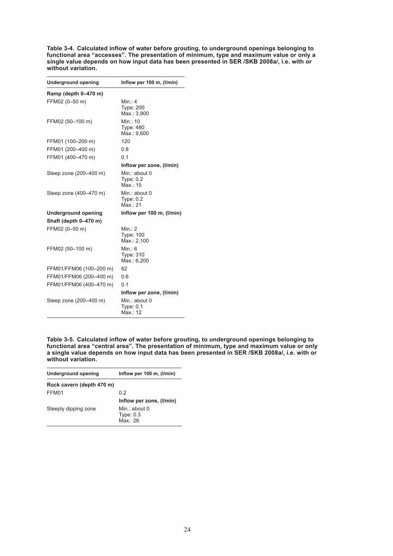
3.4 Calculation resultA summary of the results of the inflow calculations before grouting is found in Table 3-4 to Table 3-7, see Appendix B for input data. The results correspond to “ground behaviour” in different conditions (fracture domains or deformation zones).
Values presented in Tables 3-4 to 3-7 give an average value for minimum, type and maximum respectively for the individual underground openings. In practice the values for the inflow of water will vary within the functional area, especially for accesses (ramp and shaft) where a groundwater mean pressure has been assumed over the selected depth interval, see Appendix B. For example, this can be illustrated in that the inflow of water before grouting the ramp in the depth interval 100–200 m varies from 91 to 154 l/min, 100 m depending on where the 100 metre length is located in the interval.
24
Table 3-4. Calculated inflow of water before grouting, to underground openings belonging to functional area “accesses”. The presentation of minimum, type and maximum value or only a single value depends on how input data has been presented in SER /SKB 2008a/, i.e. with or without variation.
Underground opening Inflow per 100 m, (l/min)
Ramp (depth 0–470 m)FFM02 (0–50 m) Min.: 4
Type: 200 Max.: 3,900
FFM02 (50–100 m) Min.: 10 Type: 480 Max.: 9,600
FFM01 (100–200 m) 120FFM01 (200–400 m) 0.8FFM01 (400–470 m) 0.1
Inflow per zone, (l/min)Steep zone (200–400 m) Min.: about 0
Type: 0.2 Max.: 15
Steep zone (400–470 m) Min.: about 0 Type: 0.2 Max.: 21
Underground opening Inflow per 100 m, (l/min)Shaft (depth 0–470 m)FFM02 (0–50 m) Min.: 2
Type: 100 Max.: 2,100
FFM02 (50–100 m) Min.: 6 Type: 310 Max.: 6,200
FFM01/FFM06 (100–200 m) 62FFM01/FFM06 (200–400 m) 0.6FFM01/FFM06 (400–470 m) 0.1
Inflow per zone, (l/min)Steep zone (200–400 m) Min.: about 0
Type: 0.1 Max.: 12
Table 3-5. Calculated inflow of water before grouting, to underground openings belonging to functional area “central area”. The presentation of minimum, type and maximum value or only a single value depends on how input data has been presented in SER /SKB 2008a/, i.e. with or without variation.
Underground opening Inflow per 100 m, (l/min)
Rock cavern (depth 470 m)FFM01 0.2
Inflow per zone, (l/min)Steeply dipping zone Min.: about 0
Type: 0.3 Max.: 26

25
Table 3-6. Calculated inflow of water before grouting, to underground openings belonging to functional area “deposition area” including transport tunnels. The presentation of minimum, type and maximum value or only a single value depends on how input data has been presented in SER /SKB 2008a/, i.e. with or without variation.
Underground opening Inflow per 100 m, (l/min)
Deposition tunnel (depth 470 m)FFM01/FFM06 0.1
Inflow per zone, (l/min)Steep zone Min.: about 0
Type: 0.2 Max: 22Inflow per 100 m, (l/min)
Transport and main tunnel (depth 470 m)FFM01/FFM06 0.1
Inflow per zone, (l/min)Transport tunnel: Steep zone Min.: about 0
Type: 0.2 Max: 23
Transport tunnel: Steep zone (ZFME-NE0060A)
0.7
Main tunnel: Steep zone Min.: about 0 Type: 1.2 Max: 120
Table 3-7. Calculated inflow of water before grouting, to ventilation shafts in functional area “deposition area”. The presentation of minimum, type and maximum value or only a single value depends on how input data has been presented in SER /SKB 2008a/, i.e. with or without variation.
Underground opening Ingress per 100 m (l/min)
Exhaust shaft SA01 (0–470 m)FFM02 (depth 0–50m) Min.: 2
Type: 100 Max.: 2,000
FFM02 (depth 50–100m) Min.: 6 Type: 300 Max:. 6,000
FFM01 (depth 100–200m) 60FFM01 (depth 200–300m) 0.5FFM01 (depth 330–400m) 0.7FFM01 (depth 400–470m) 0.1
Inflow per zone, (l/min)Gently dipping zone ZFMB7 (depth 300–330m) 6.3Underground opening Inflow per 100 m, (l/min)Exhaust shaft SA02 (0–470 m)FFM02 (depth 0–50m) Min.: 2
type: 100 max.: 2,000
FFM02 (depth 50–100m) Min.: 6 type: 300 max:. 6,000
FFM02 (depth 100–170m) 22FFM01 (depth 170–200m) 74FFM01 (depth 200–400m) 0.6FFM01 (depth 400–470m) 0.1
26
3.5 ConclusionsIt can be stated that the greatest inflow of water can be anticipated in ramp and shafts at the depth interval 0–100 m. Inflow of water up to almost 10 m3/min, 100 m tunnel or shaft, can occur in the most unfavourable case unless grouting measures are undertaken. It must also be noted that this most unfavourable case corresponds to a maximum conductivity value in the rock mass applied for the entire stretch of tunnels and shafts at 0–100 m depth, which is considered unlikely. Even with more probable values of hydraulic conductivity, extensive grouting measures will most likely be needed along certain stretches to ensure that the requirement on maximum permitted inflow is fulfilled for the ramp and the shafts. Extensive grouting is also necessary at this depth interval to create a reasonable working environment and also to facilitate safe and efficient execution of other rock work.
Due to the application of one constant mean water pressure over the different depth intervals in the ramp and shafts, the inflow also represents a mean value per 100 m tunnel/shaft over the depth interval. If a continually increasing water pressure for each 100 m depth interval would be considered, a span of the water inflow will be obtained instead of one single value. In principle this implies that both lower and higher values within each depth interval can be anticipated.
The inflow of water decreases at greater depth and the need of grouting measures decreases accordingly. At depths greater than 200 m only minor inflow is anticipated on passing deformation zones. It is likely that no grouting will be required along long sections at greater depth than 200 m, above all in underground openings in the central area and the deposition area. However extensive grouting must be anticipated when passing deformation zones in the deposition areas. Especially can extensive grouting be expected in deposition tunnels, when passing deformation zones, because of the high requirements.

27
4 Basis of grouting measures
4.1 IntroductionAccording to UDP /SKB 2007/, design in step D2 can be performed by using analytical calculation methods and/or experience from other grouting work. In this stage it is regarded as motivated to configure the grouting measures based on a combination of experience from other projects and calculations.
Experience from grouting work is described in Appendix A. A summary of the description of experience in Appendix A is made in Chapter 4.2.
The following calculations have been made:
• Assessment of the degree of difficulty by calculating necessary sealing effect.
• Calculations of which fracture apertures that must be sealed.
Detailed descriptions of calculation methods and also references to them are presented in /Emmelin et al. 2007/.
4.2 Summary of grouting experienceExperience of grouting at great depth in tunnels, in shaft sinking and in deep boreholes from the surface indicate that grouting can be carried out down to several hundred metres depth. However, this does not mean that such grouting is easy to carry out or that the need of complementary sealing work can be excluded. Grouting has not been sufficient in some projects and in some cases freezing combined with lining had to be used instead of grouting.
The possibility to succeed with the grouting depends to a great extent on the characteristics of the rock mass and the requirements on tightness that are specified. Other aspects that are significant with regard to grouting at great depth are the risks of flushing out, dilution and erosion of the grout. To diminish the effect of these phenomena, the grouting measures and the grout must be subjected to thorough analysis and testing before the actual grouting begins.
Probe drilling is an important success factor when driving through horizontal structures, i.e. to avoid large inflow of water in connection with the tunnel front without any forewarning.
Grouting in sink shafts has been carried out with good results according to the same principles as when grouting in tunnels. Probe drilling is especially important from the point of view of safety when driving sink shafts, because uncontrolled inflow of water can quickly flood a shaft.
Experience is available from a number of different drilling procedures for the drilling of long boreholes, eg, tophammer drilling, down-the-hole drilling, water-powered drilling systems or core drilling. Which drilling procedure is most suitable for Forsmark must be investigated further. Furthermore, it is recommended that the proposed grout is composed with regard to separation and dilution. In addition, a number of practical aspects must also be considered and checked when grouting in deep boreholes, eg, handling of grout in transport down the hole, pressurizing of the grout, type of drill tubes, hoses and packers.
Pre-grouting with silica sol has so far shown good sealing results in superficial conditions, but the grouting procedure and equipment must be developed to achieve a more rational procedure. Moreover, the grouting procedure using silica sol puts greater demands on personnel and equipment compared to conventional cement grouting. Good results of post-grouting using silica sol have been achieved as well as results where no sealing effect was achieved, i.e. similar experience to that of post-grouting in general.

28
4.3 Assessing the degree of difficulty for groutingThe degree of difficulty has been linked to how difficult it is to fulfil the requirement concerning the inflow of water, i.e. necessary sealing effect, and also the necessary conductivity of the grouted zone (Kg). The higher the requirement on sealing effect and tightness of the grouted zone, the more difficult the grouting can be expected to be /Eriksson and Stille 2005/. Difficult grouting can demand more extensive design, systematic pre-grouting, more grouting holes, more grouting rounds, more extensive testing of grout and need of special equipment.
It should be noted that the degree of difficulty is not fully correlated to the grouting types described in Chapter 3. A low degree of difficulty probably requires grouting type 1–2, while higher requirements on sealing require grouting type 2–3 to a greater extent.
The sealing effect is calculated according to /Dalmalm 2001/ using Equation 4-1:
4-1
where ungroutedq and groutedq (m3/s, m) are calculated according to Equation 3-1, 3-2 and 3-3, with Kg = K in the non-grouted case.
Necessary sealing of the grouted zone, Kg, has been obtained by setting the values of Kg for respective depth intervals so that the requirements with regard to maximum permitted inflow of water are fulfilled for the different underground openings. The requirement on maximum permitted inflow refers in this case to inflow for the total length of the individual underground openings in the underground facility.
Based on the experience of grouting performed, i.e. Appendix A, the assessment is that the lowest hydraulic conductivity that can probably be achieved in the rock mass outside of the deformation zones is 1·10–9 m/s when using a cement-based grout.
However, when grouting from surface level in the exhaust shafts SA01 and SA02 a maximum tightness corresponding to 1·10–8 m/s has been assumed for FFM01 and depth 100–200 m. This is motivated by the anticipated higher degree of difficulty when grouting from surface level compared to grouting being carried out from the bottom of the shaft or at tunnel level.
In the more fractured part of the rock mass, FFM02 depth of 0–100 m, it is assumed that a maximum tightness corresponding to a conductivity of 1·10–7–1·10–8 m/s is possible.
For the deformation zones a corresponding value of 1·10–8 m/s is assumed. This is motivated in that a higher fracture frequency and more heterogeneous conditions occur in deformation zones.
A guide value in assessing maximum tightness of the grouted zone is also that the hydraulic conductivity before grouting can be reduced by a maximum of about twice the power of ten.
When using silica sol, grouting that has been performed in grouting trials indicate that a further power of ten lower hydraulic conductivity, i.e. about 1·10–10 m/s, can be achieved in the rock mass outside the deformation zones /Funehag 2007/. For deformation zones a corresponding value of 1·10–9 m/s is assumed, based on result from /Funehag 2009/.
The mean thickness of the grouted zone, t, has been set at 5 m. This value is set considering the requirement on limited grout spread and that the possible rock bolts should not be able to pass the grouted zone. In the more fractured rock in fracture domain FFM02, 0–100 m depth, the average grouted thickness has been assumed at 10 m. The motive for selecting a higher value in these parts of the rock mass is that a more extensive grout spread must be sought to enable filling of as many fractures as possible. Grouting at greater depth is probably made in more distinct fractures zones, which means that better control of the grout spread should be possible. The values of the zone thickness are however uncertain since few attempts to measure the grout spread thickness has been made. The choice of thickness for the grouted zone is however only of minor significance in calculating the resulting tightness.
ungrouted
grouted
−1
29
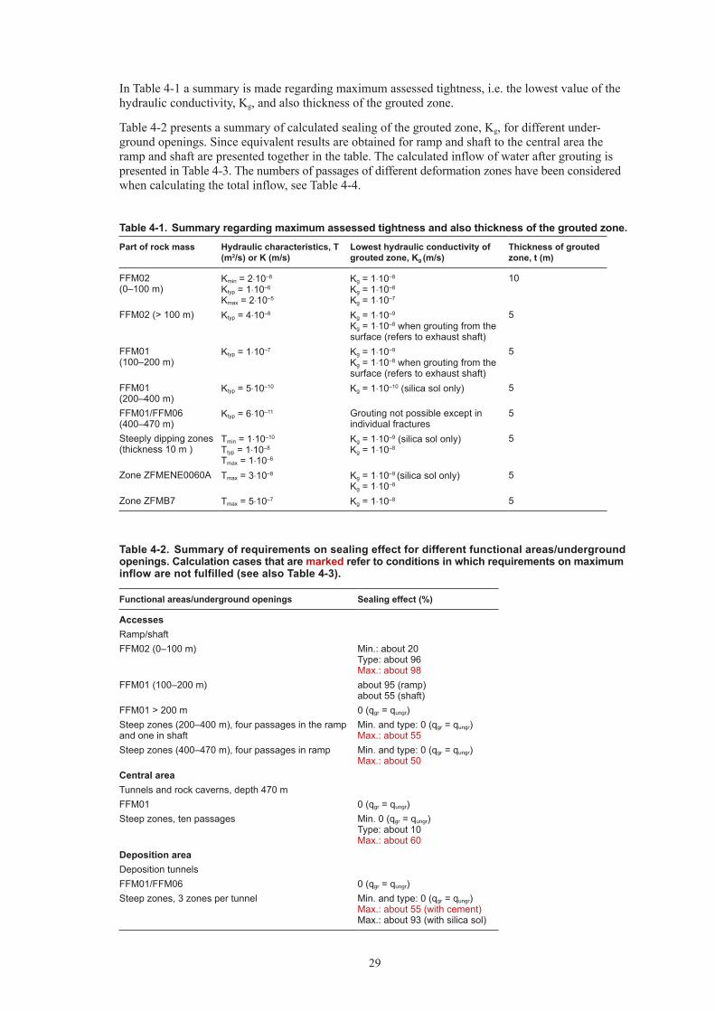
In Table 4-1 a summary is made regarding maximum assessed tightness, i.e. the lowest value of the hydraulic conductivity, Kg, and also thickness of the grouted zone.
Table 4-2 presents a summary of calculated sealing of the grouted zone, Kg, for different under-ground openings. Since equivalent results are obtained for ramp and shaft to the central area the ramp and shaft are presented together in the table. The calculated inflow of water after grouting is presented in Table 4-3. The numbers of passages of different deformation zones have been considered when calculating the total inflow, see Table 4-4.
Table 4-1. Summary regarding maximum assessed tightness and also thickness of the grouted zone.Part of rock mass Hydraulic characteristics, T
(m2/s) or K (m/s)Lowest hydraulic conductivity of grouted zone, Kg (m/s)
Thickness of grouted zone, t (m)
FFM02 (0–100 m)
Kmin = 2⋅10–8
Ktyp = 1⋅10–6
Kmax = 2⋅10–5
Kg = 1⋅10–8
Kg = 1⋅10–8
Kg = 1⋅10–7
10
FFM02 (> 100 m) Ktyp = 4⋅10–8 Kg = 1⋅10–9
Kg = 1⋅10–8 when grouting from the surface (refers to exhaust shaft)
5
FFM01 (100–200 m)
Ktyp = 1⋅10–7 Kg = 1⋅10–9
Kg = 1⋅10–8 when grouting from the surface (refers to exhaust shaft)
5
FFM01 (200–400 m)
Ktyp = 5⋅10–10 Kg = 1⋅10–10 (silica sol only) 5
FFM01/FFM06 (400–470 m)
Ktyp = 6⋅10–11 Grouting not possible except in individual fractures
5
Steeply dipping zones (thickness 10 m )
Tmin = 1⋅10–10
Ttyp = 1⋅10–8
Tmax = 1⋅10–6
Kg = 1⋅10–9 (silica sol only) Kg = 1⋅10–8
5
Zone ZFMENE0060A Tmax = 3⋅10–8 Kg = 1⋅10–9 (silica sol only)
Kg = 1⋅10–85
Zone ZFMB7 Tmax = 5⋅10–7 Kg = 1⋅10–8 5
Table 4-2. Summary of requirements on sealing effect for different functional areas/underground openings. Calculation cases that are marked refer to conditions in which requirements on maximum inflow are not fulfilled (see also Table 4-3).
Functional areas/underground openings Sealing effect (%)
AccessesRamp/shaftFFM02 (0–100 m) Min.: about 20
Type: about 96 Max.: about 98
FFM01 (100–200 m) about 95 (ramp) about 55 (shaft)
FFM01 > 200 m 0 (qgr = qungr)Steep zones (200–400 m), four passages in the ramp and one in shaft
Min. and type: 0 (qgr = qungr) Max.: about 55
Steep zones (400–470 m), four passages in ramp Min. and type: 0 (qgr = qungr) Max.: about 50
Central areaTunnels and rock caverns, depth 470 mFFM01 0 (qgr = qungr)Steep zones, ten passages Min. 0 (qgr = qungr)
Type: about 10 Max.: about 60
Deposition areaDeposition tunnelsFFM01/FFM06 0 (qgr = qungr)Steep zones, 3 zones per tunnel Min. and type: 0 (qgr = qungr)
Max.: about 55 (with cement) Max.: about 93 (with silica sol)

30
Contd. Table 4-2.
Functional areas/underground openings Sealing effect (%)
Deposition areaMain tunnels/transport tunnelsFFM01/FFM06 0 (qgr = qungr)Transport: Steep zones, total length of passages about 500 m Min. and type: 0 (qgr = qungr)
Max.: about 50Transport: Zone ZFMENE0060A, 20 m, 2 passages 0 (qgr = qungr)Main: Steep zones, total length of passages about 2,200 m Min. and type: 0 (qgr = qungr)
Max.: 80Exhaust shaft (0–470 m)FFM02 (0–100m) Min.:10–20
Type: about 95 Max.: about 98
FFM02 (> 100m) about 30FFM01 (100–200m) about 55FFM01 (> 200m) 0 (qgr = qungr)Gently dipping zone, ZFMB7, one zone passage about 30 m long at 310m depth
about 10
Table 4-3. Calculated inflow of water after grouting for different functional areas with input data according to Appendix B.
Functional areas/underground openings
Inflow, incl. passing zones, per 100 m (l/min)
Maximum permitted inflow per 100 m (l/min)
Comments
AccessesRamp, depth 0–470 m Min: 0.2
Type: 4 Max: 190
10 In the most unfavourable conditions the requirement on tightness is not fulfilled.
Shaft, depth 0–470 m Min: 0.1 Type: 8 Max: 150
10 In the most unfavourable conditions the requirement on tightness is not fulfilled.
Central areaTunnels and rock caverns
Min.: 0.2 Type: 0.4 Max.: 13
10 Grouting of zones is only needed in the most unfavourable case.
Deposition areaDeposition tunnels, with cement grouting
Min.: 0.1 Type: 0.4 Max.: 11
1.7 When a zone have a T > about 5·10–8 m/s the requirement on tightness is not to be fulfilled
Deposition tunnels, with silica sol grouting
Min.: 0.1 Type: 0.3 Max.: 1.6
1.7 Sealing must be made at Kg = 1⋅10–9 m/s in zones with T> 5·10–8 m/s, for the requirement on tightness to be fulfilled.
Transport tunnels Min.: 0.1 Type: 0.3 Max.: 14
10 In the most unfavourable conditions sealing must be made at Kg= 1⋅10–8 to 1⋅10–9 m/s for the requirement on tightness to be fulfilled.
Transport tunnels, with ZFMENE0060A
0.7 10 The calculated inflow is base on the transmissivity value, for the zone, in SER /SKB 2008a/
Main tunnels Min.: 0.1 Type: 1.3 Max.: 140
10 In the most unfavourable conditions sealing must be made at Kg= 1⋅10–8 to 1⋅10–9 m/s for the requirement on tightness to be fulfilled.
Exhaust shaft (0–470 m) SA01, incl. ZFMB7
Min.: 0.1 Type: 9 Max.: 140
10 In the most unfavourable conditions the requirement on tightness is not fulfilled. The calculated inflow in the zone is base on the transmissivity value in SER /SKB 2008a/
Exhaust shaft (0–470 m) SA02
Min.: 0.1 Type: 6 Max.: 25
10 In the most unfavourable conditions the requirement on tightness is not fulfilled.

31
Minimum, type and maximum values refer to the calculated values for the respective hydraulic characteristics of the fracture domain FFM02 (0–100 m) and of the deformation zones. For the rock mass in FFM01, SER presents no variation in the same way as for the upper part of the rock mass, and therefore only one value is presented in these cases.
Depending on the actual hydraulic characteristics of the rock mass and the sealing effect obtained in FFM02 at 0–100 m depth interval, different extent of the grouting work can be needed in FFM01, 100–200 m depth, to cope with the requirement on maximum permitted inflow for the whole ramp and shafts. Accordingly, preparedness for different grouting types must be available at the depth interval 100–200 m in fracture domain FFM01, and also through deformation zones at greater depth.
Since the calculated inflow strongly depend on the hydraulic head (depth), the inflow to the ramp and shafts will increase with depth for the same hydraulic conductivity, see Section 3.3.1. The increased inflow in the ramp and shafts, with depth, are showed in Figure 4-1.
Table 4-4. Number of passages and parts of deformation zones for deposition tunnels based on layout according to /Hansson et al. 2008/.
Main tunnel, acc. to layout, see Figure 2-5
Number of dep. tunnels (qty)
Span of intersections per dep. tunnel (qty)
DA 23 Min.: 0 (11 tunnels)
Median: 1
Max: 2 (4 tunnels)
DB 59 Min.: 1 (8 tunnels)Median: 2Max: 6 (3 tunnels)
DC 85 Min.: 0 (13 tunnels)Median: 2Max: 4 (6 tunnels)
DD 79 Min.: 0 (16 tunnels)Median: 2Max: 4 (9 tunnels)
Figure 4-1. The calculated inflow in the ramp and shafts SA01 and SA02, with depth (hydraulic head). Only one value of the hydraulic conductivity (type) is shown in SER /SKB 2008a/, for depth below 100 m see Section 3.3.1.
Depth vs inflow, after groting
0
50
100
150
200
250
300
350
400
450
500
0,1 1,0 10,0 100,0 1000,0
Inflow (l/min 100m)
Dep
th (m
)
Ramp, maxRamp, typeRamp, minShaft SA01 and 02, maxShaft SA01 and 02, minShaft SA02, typeShaft SA01, type
32
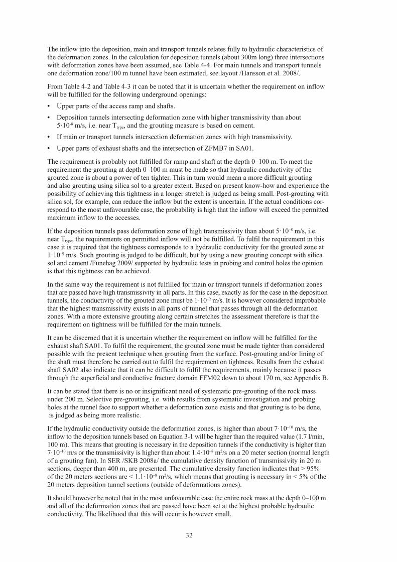
The inflow into the deposition, main and transport tunnels relates fully to hydraulic characteristics of the deformation zones. In the calculation for deposition tunnels (about 300m long) three intersections with deformation zones have been assumed, see Table 4-4. For main tunnels and transport tunnels one deformation zone/100 m tunnel have been estimated, see layout /Hansson et al. 2008/.
From Table 4-2 and Table 4-3 it can be noted that it is uncertain whether the requirement on inflow will be fulfilled for the following underground openings:• Upper parts of the access ramp and shafts.• Deposition tunnels intersecting deformation zone with higher transmissivity than about
5·10-8 m/s, i.e. near Ttype, and the grouting measure is based on cement.• If main or transport tunnels intersection deformation zones with high transmissivity.• Upper parts of exhaust shafts and the intersection of ZFMB7 in SA01.
The requirement is probably not fulfilled for ramp and shaft at the depth 0–100 m. To meet the requirement the grouting at depth 0–100 m must be made so that hydraulic conductivity of the grouted zone is about a power of ten tighter. This in turn would mean a more difficult grouting and also grouting using silica sol to a greater extent. Based on present know-how and experience the possibility of achieving this tightness in a longer stretch is judged as being small. Post-grouting with silica sol, for example, can reduce the inflow but the extent is uncertain. If the actual conditions cor-respond to the most unfavourable case, the probability is high that the inflow will exceed the permitted maximum inflow to the accesses.
If the deposition tunnels pass deformation zone of high transmissivity than about 5·10–8 m/s, i.e. near Ttype, the requirements on permitted inflow will not be fulfilled. To fulfil the requirement in this case it is required that the tightness corresponds to a hydraulic conductivity for the grouted zone at 1·10–9 m/s. Such grouting is judged to be difficult, but by using a new grouting concept with silica sol and cement /Funehag 2009/ supported by hydraulic tests in probing and control holes the opinion is that this tightness can be achieved.
In the same way the requirement is not fulfilled for main or transport tunnels if deformation zones that are passed have high transmissivity in all parts. In this case, exactly as for the case in the deposition tunnels, the conductivity of the grouted zone must be 1·10–9 m/s. It is however considered improbable that the highest transmissivity exists in all parts of tunnel that passes through all the deformation zones. With a more extensive grouting along certain stretches the assessment therefore is that the requirement on tightness will be fulfilled for the main tunnels.
It can be discerned that it is uncertain whether the requirement on inflow will be fulfilled for the exhaust shaft SA01. To fulfil the requirement, the grouted zone must be made tighter than considered possible with the present technique when grouting from the surface. Post-grouting and/or lining of the shaft must therefore be carried out to fulfil the requirement on tightness. Results from the exhaust shaft SA02 also indicate that it can be difficult to fulfil the requirements, mainly because it passes through the superficial and conductive fracture domain FFM02 down to about 170 m, see Appendix B.
It can be stated that there is no or insignificant need of systematic pre-grouting of the rock mass under 200 m. Selective pre-grouting, i.e. with results from systematic investigation and probing holes at the tunnel face to support whether a deformation zone exists and that grouting is to be done, is judged as being more realistic.
If the hydraulic conductivity outside the deformation zones, is higher than about 7·10–10 m/s, the inflow to the deposition tunnels based on Equation 3-1 will be higher than the required value (1.7 l/min, 100 m). This means that grouting is necessary in the deposition tunnels if the conductivity is higher than 7·10–10 m/s or the transmissivity is higher than about 1.4·10–8 m2/s on a 20 meter section (normal length of a grouting fan). In SER /SKB 2008a/ the cumulative density function of transmissivity in 20 m sections, deeper than 400 m, are presented. The cumulative density function indicates that > 95% of the 20 meters sections are < 1.1·10–8 m2/s, which means that grouting is necessary in < 5% of the 20 meters deposition tunnel sections (outside of deformations zones).
It should however be noted that in the most unfavourable case the entire rock mass at the depth 0–100 m and all of the deformation zones that are passed have been set at the highest probable hydraulic conductivity. The likelihood that this will occur is however small.

33
4.4 Calculation of fracture aperturesSER /SKB 2008a/ presents the hydraulic fracture statistics, with fracture frequency and transmissivity for each fracture domain and for different depth intervals.
Table 4-5 presents fracture statistics for relevant fracture domains and depth intervals.
Decisive for what tightness can be achieved is how the grout penetrates and spreads in fractures in the rock mass. Grouts have however different possibilities of penetrating the finer fractures depending on composition of the grout, eg, grain size of cement, mixing procedure and additives. The analyses aiming at a grouting design must therefore result in an assessment of the aperture of fractures that must be sealed. It is not so simple however to determine the aperture of fractures, since the network of fractures by its nature is complicated and must be contemplated in a 3-D perspective and also with regard to the type of flow-dimensionality that occurs. Simplification of the fracture aperture can be made by the concept of the hydraulic fracture aperture /Snow 1968/ expressed by Equation 4-2:
4-2
where Ts = transmissivity of an individual fracture (m2/s) bhyd = hydraulic fracture aperture (m) ρw = density of water (kg/m3) µw = viscosity of water (Pas) g = acceleration of gravity (m/s2)
Equation 4-2 gives:
4-3
The hydraulic fracture aperture is based on assumptions of simplified relationships, eg, that the fractures are plane-parallel with a constant fracture aperture. It should be noted that the hydraulic aperture is smaller than the average physical aperture /Eriksson and Stille 2005/. How much smaller is however not distinct.
It is not obvious which fractures that needs to be grouted. By using Equation 4-2 for a specific number of fractures, it can be seen that an equivalent sealing effect can for example be obtained if the fractures with a large aperture are sealed to a great extent or whether all fractures are sealed to a smaller extent. Sealing one fracture can possibly also prevent water inflow from another fracture even if this is not sealed.
Table 4-5. Hydraulic fracture statistics for the relevant domains FFM01, FFM02 and FFM06 per depth interval (based on SER, /SKB 2008a/).
Fracture domain and depth interval Transmissivity of individual water-bearing fractures, minimum, average, maximum (m2/s)
Frequency of the water-bearing fractures (st/m)
FFM02 (0–100 m) Min. = 1⋅10–6 Average = 3.2⋅10–5
Max. = 1⋅10–3
0.306
FFM01 (100–200 m) Min. = 2.5⋅10–10 Average = 1.4⋅10–8
Max. = 4.7⋅10–5
0.153
FFM01 (200–400 m) Min. = 2.7⋅10–10 Average = 3.1⋅10–9
Max. = 1.8⋅10–7
0.045
FFM01/FFM06 (> 400 m) Min. = 6.2⋅10–10 Average = 6.5⋅10–9
Max. = 8.9⋅10–8
0.006
w
whyds
gbT
µρ⋅
⋅⋅=
12
3
301,0 shyd Tb ⋅≈
34
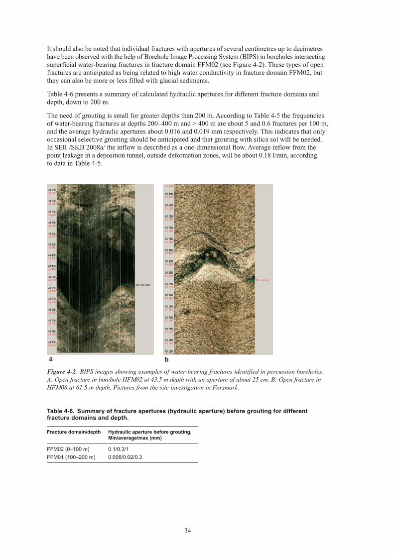
It should also be noted that individual fractures with apertures of several centimetres up to decimetres have been observed with the help of Borehole Image Processing System (BIPS) in boreholes intersecting superficial water-bearing fractures in fracture domain FFM02 (see Figure 4-2). These types of open fractures are anticipated as being related to high water conductivity in fracture domain FFM02, but they can also be more or less filled with glacial sediments.
Table 4-6 presents a summary of calculated hydraulic apertures for different fracture domains and depth, down to 200 m.
The need of grouting is small for greater depths than 200 m. According to Table 4-5 the frequencies of water-bearing fractures at depths 200–400 m and > 400 m are about 5 and 0.6 fractures per 100 m, and the average hydraulic apertures about 0.016 and 0.019 mm respectively. This indicates that only occasional selective grouting should be anticipated and that grouting with silica sol will be needed. In SER /SKB 2008a/ the inflow is described as a one-dimensional flow. Average inflow from the point leakage in a deposition tunnel, outside deformation zones, will be about 0.18 l/min, according to data in Table 4-5.
Figure 4-2. BIPS images showing examples of water-bearing fractures identified in percussion boreholes. A: Open fracture in borehole HFM02 at 43.5 m depth with an aperture of about 25 cm. B: Open fracture in HFM06 at 61.5 m depth. Pictures from the site investigation in Forsmark.
Table 4-6. Summary of fracture apertures (hydraulic aperture) before grouting for different fracture domains and depth.
Fracture domain/depth Hydraulic aperture before grouting, Min/average/max (mm)
FFM02 (0–100 m) 0.1/0.3/1FFM01 (100–200 m) 0.006/0.02/0.3
ba
35
For the deformation zones, considerable variations in fracture aperture can be anticipated depending on transmissivity and depth of the zones. Accordingly, hydraulic apertures both bigger and smaller than 100 µm can occur in the deformation zones.
In design step D2, design criteria according to UDP /SKB 2007/ indicate that cement based grouts are to be used for “larger” fracture apertures, i.e. > 0.1 mm, and silica sol for “smaller” fracture apertures, i.e. ≤0.1 according to /Emmelin et al. 2007/. In SER /SKB 2008a/ the cumulative density function of transmissivity in 20 m sections, deeper than 400 m, are presented. The cumulative density function indicates that none (0%) of the 20 meters sections that have a transmissivity of 1·10–6 m2/s or higher. This means that grouting with cement outside of deformation zones is not of interest.
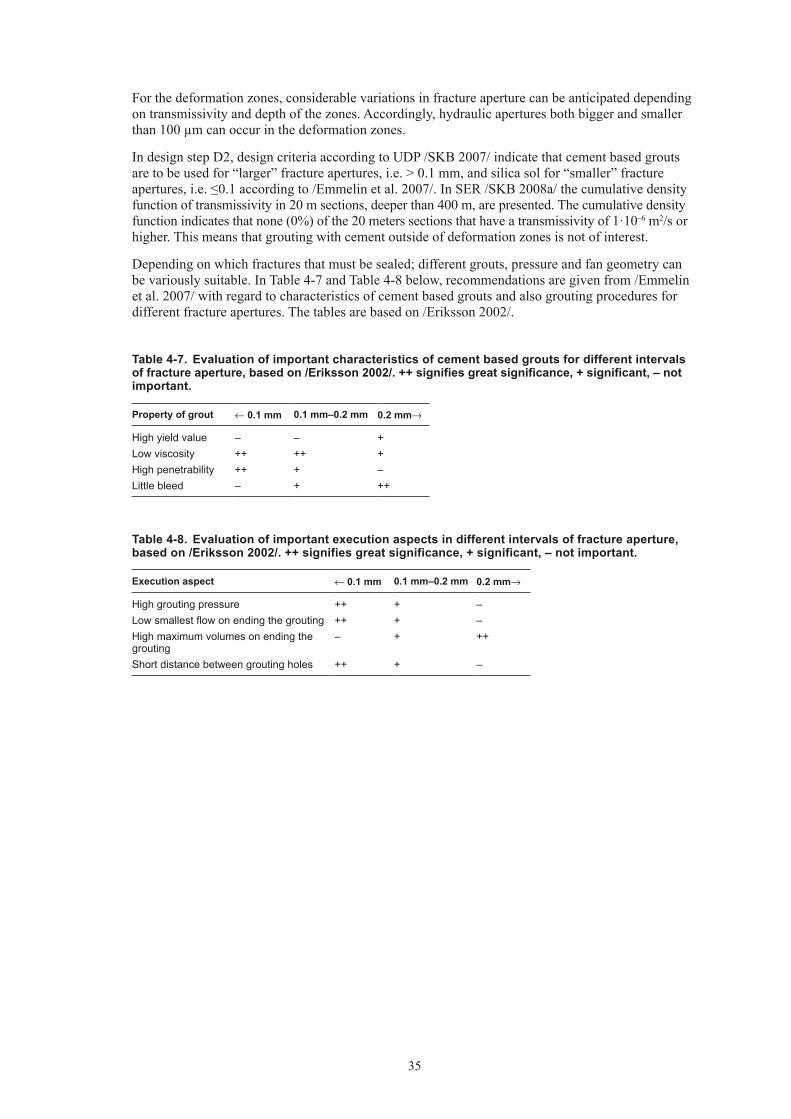
Depending on which fractures that must be sealed; different grouts, pressure and fan geometry can be variously suitable. In Table 4-7 and Table 4-8 below, recommendations are given from /Emmelin et al. 2007/ with regard to characteristics of cement based grouts and also grouting procedures for different fracture apertures. The tables are based on /Eriksson 2002/.
Table 4-7. Evaluation of important characteristics of cement based grouts for different intervals of fracture aperture, based on /Eriksson 2002/. ++ signifies great significance, + significant, – not important.
Property of grout ← 0.1 mm 0.1 mm–0.2 mm 0.2 mm→
High yield value – – +Low viscosity ++ ++ +High penetrability ++ + –Little bleed – + ++
Table 4-8. Evaluation of important execution aspects in different intervals of fracture aperture, based on /Eriksson 2002/. ++ signifies great significance, + significant, – not important.
Execution aspect ← 0.1 mm 0.1 mm–0.2 mm 0.2 mm→
High grouting pressure ++ + –Low smallest flow on ending the grouting ++ + –High maximum volumes on ending the grouting
– + ++
Short distance between grouting holes ++ + –


37
5 Grouting measures
5.1 Strategy for establishing grouting measuresThe following section presents the strategy that has been chosen as the starting point for configuring the grouting measures, i.e. fan geometry, grout, execution, equipment and checks. The strategy is based on the premises stated in Chapter 2, results of inflow calculations before grouting (Chapter 3.4), experience of performed grouting (Appendix A) and analyses of degree of difficulty (Chapter 4.3) and fracture aperture (Chapter 4.4). The following strategy has been chosen:• Test drilling and grouting trials from surface level are to be made before starting on ramp and shafts
to the central area. This drilling and grouting should be carried out in possible locations for ramp and shafts. In this way, location and characteristics of the horizontal fracture zones can be assessed and the drilling and grouting measures tested and adjusted before large-scale production begins.
• Large-scale curtain grouting is to be carried out from surface level around all access parts between surface level and the depth 50 or 100 m. Curtain grouting around the ramp is to be made 50 m long and for vertical shafts 100 m. The aim of the curtain grouting is to seal the large superficial fractures in order to enable a more effective and safe rock excavation. Results of test drilling and grouting trials are to be utilised in the decisions concerning extent and detailed solutions for the large-scale curtain grouting.
• Niches in the ramp are to be used for grouting in stretches about 100 m long around the drilled shafts (lift and ventilation shafts in the central area). Both drilling and grouting is facilitated in this way, enabling better sealing results.
• The skip shaft is grouted mainly from the face of the excavation. Some of the curtain grouting holes are extended, i.e. > 100m, to create better conditions for the shaft sinking. Less time will then be needed for grouting from the bottom of the shaft and a more rational shaft sinking is facilitated.
• Preparedness for rapid hardening grout (eg, with added accelerators) is to be available as well as alternative sealing methods (eg, freezing and/or lining) when excavating ramp and shafts.
• Cement-based grouts are to be used if possible. It is suggested that silica sol could be used as a complement if a second round of pre-grouting is needed, and for post-grouting of point leakage. In deposition tunnels, with high requirements, a new grouting concept with silica sol and cement /Funehag 2009/ will be needed from the start of the first round of pre-grouting.
• Grouting of different underground openings under the depth 200 m is made as a selective pre-grouting, with systematic investigation and probing holes. However, extensive and systematic pre-grouting can be expected when passing deformation zones at depth below 200 m.
• Individual fractures should if possible be identified and grouted in deposition tunnels in order to avoid post-grouting of point leakage. Based on the analyses regarding the difficulty for grouting, the main aim should be to identify deformation zones. Due to the difficulty in identifying individual water bearing fractures, point leakage > 1 l/min in deposition tunnels will mainly be sealed by post-grouting.
5.2 General principles5.2.1 Grouting typesThe grouting measures should according to SER /SKB 2008a/ be grouped into three so called grouting types. The grouting types include different measures for pre-grouting, such as type of grout, fan geometry and execution. In the following descriptions of grouting measures these grouting types have been defined as follows:• Grouting type 1 (GrT1): Selective pre-grouting• Grouting type 2 (GrT2): Systematic pre-grouting• Grouting type 3 (GrT3): Systematic pre-grouting including special measures

38
Special measures (GrT3) intend scenarios with high water-bearing zones or the new concept with silica sol and cement.
In design step D1 for Forsmark /Brantberger et al. 2006/ seven “Type groutings” are described that are linked to the different hydrogeological structures. For the most part the principles of the different grouting types, are the same as for the “Type groutings” in design step D1.
5.2.2 GroutsThe main principle is that the grout is selected in relation to the hydraulic fracture aperture that has been estimated, i.e. cement based for “larger” apertures and silica sol for “smaller” apertures respectively. It may be necessary to adjust the recipe somewhat to obtain the desired properties depending on estimated fracture aperture.
Recipes and characteristics for cement based grouts and silica sol have been provided by SKB. Three recipes are presented there for cement based grouts, so-called “injection grout”, “stop grout” and “plug grout”. The different recipes are to be used in different situations; “injection grout” for normal grouting, “stop grout” to limit spread and “plug grout” to fill tight boreholes. All of these cement based grouts contain cement, silica slurry (silica particles dispersed in water) and plasticizer. Furthermore, three examples are presented with different compositions of silica sol with varying degree of accelerator.
Recipes and characteristics for cement based grouts and silica sol are presented in Appendix C.
5.2.3 Grouting fanAll grouting types are based on base grouting fans which in detail depend on geometry of the individual underground openings of the underground facility. Figure 5-1 illustrates the base grouting fans for the different geometries in the deposition area. It should be noted that holes in the bottom of the deposition tunnels will only be drilled in deformation zones. A more detailed design of the fans is done after introductory grouting and analyses of results.
In some of the grouting types control holes will also be drilled. In the control holes hydraulic tests should be made with the aim of checking the sealing result.
5.2.4 Execution and equipmentThe grouting pressure (∆p), i.e. total pressure minus groundwater pressure, is based on the relationship to the groundwater pressure (pw) and rock mass load (ρbgd) according to Equation 5-1:
5-1
Figure 5-1. Principle execution of base pre-grouting fans in the deposition area; a more detailed design of the grouting fans is made after grouting in ramp and central area and holes should not intersect deposition hole.
wb ppgd 23 ≥∆≥ρ

39
This means that the grouting pressure should be at least twice the groundwater pressure /Axelsson 2006/. This gives relatively large grouting pressure, about 90 bar at full groundwater pressure at repository depth, compared to conventional grouting in superficial conditions. The reason for recom-mending the relatively large overpressure is partly to avoid reverse flow when grouting stops and partly to prevent erosion in the grouting before it reaches sufficiently high strength. If the cement-based grout has a certain yield value the grouting pressure for cement based grout can be somewhat lower than for silica sol which lacks yield value.
For practical and production-adapted grouting the grout injection time should be an important control parameter. Control of the grout injection time will enable a better control of the grout spread, which for example may be needed when grouting near ground surface. According to /Gustafson and Stille 2005/ and /Funehag 2007/ the grout injection time can be assessed in detail on the basis of theoretical relationships, in which necessary penetration length, estimated hydraulic fracture aperture, selected pressure and hole spacing, and also tested properties of the grout, constitute input data. For silica sol grout injection time must also be based on the selected gel induction time.
The experience that exists with regard to mixing cement-based grouting media of low pH is that the performance and quality of the mixing equipment is of great significance to ensure repeatable properties on repeated mixing occasions /Ranta-Korpi et al. 2007/. This also signifies that checking of equipment, cleaning and mixing times must be regular.
An adapted mixing and pumping procedure is necessary when grouting with silica sol. In the present procedure one batch is prepared for each separate grouting hole and on reaching the estimated grout injection time the grouting of the hole is stopped. The remaining grout in the equipment is emptied (from mixer to packer hose connection) and the equipment is cleaned before starting on the next grouting hole. This procedure requires more planning, logistics and time than normal, even if two holes could be grouted simultaneously. Accordingly, there is need of development with regard to equipment that could enable more efficient grouting using silica sol.
All equipment, for example hoses and couplings, must be dimensioned for the high total pressures that apply at the repository depth. For the present conventional packers this means, for example, a system with three tensioned rubber seals along the wall of the borehole.
In addition, a venting system/equipment could be provided to vent the grouting holes before grouting begins.
5.3 Choice of preliminary grouting measures in different functional areas
5.3.1 Summary of preliminary grouting measuresThe following chapter presents a summary of preliminary grouting measures for different functional areas.
Based on experience and analyses concerning the degree of difficulty and of hydraulic fracture apertures, the following grouting measures are recommended:• In ramp and shafts at the depth 0-100 m (0–50 m for the ramp) a preliminary large-scale curtain
grouting is required and then systematic, extensive pre-grouting with cement, several grouting rounds and need of special equipment. Grouting in drilled shafts is made from the surface and/or from niches.
• At the depth 100–200 m different grouting types can be needed depending on properties of the rock mass and grouting results for the upper 100 metres. Several grouting rounds and silica sol can be needed. Systematic pre-grouting should however be anticipated.
• At greater depths than 200 m none or selective grouting is anticipated except in the passage of individual fractures or deformation zones where systematic pre-grouting probably will be needed.
• It is assumed that deformation zones can be grouted first with cement, complemented with silica sol in second round, except in deposition tunnels. In deposition tunnels many of the deformation zones should be grouted from the start with a grouting measure with silica sol and cement. Pre- paredness should be available in unfavourable conditions for more time-consuming grouting, several grouting rounds, an increased use of silica sol and special equipment.

40
Table 5-1 summarises each functional area with regard to grouting type, main grout and also aspects regarding execution of grouting, such as the need of special equipment, several grouting rounds or checks. The term “cement” refers to one or several of the cement-based grouts provided by SKB. For design step D2 the assessments is that the different grouts, see Appendix C, are sufficient for the grouting that can be anticipated. For grouting, for example in the first grouting round at the depth 0–100 m, the so-called “plug grout” can be used. The “stop grout” can for example be used in a second grouting round at the depth 0–100 m, in the first round in more fractured rock at greater depth and also be applied to limit the grout spread. Lastly, the “injection grout” can be used for sealing in all fracture domains/zones and depths. Silica sol is used as complementary sealing in the second round or in the first round in deposition tunnels and also for post-grouting of point leakage. In connection with detailed design the composition of grouts may need to be adjusted. For example, particular grout properties may be required when grouting deep boreholes from the surface.
5.3.2 AccessesRampGrouting in the ramp is anticipated mainly down to a depth of 200 m.
As stated in design step D1 /see Brantberger et al. 2006/ one of the most important conditions to enable excavation and grouting of the ramp in an efficient manner is well planned and implemented probe drilling. The number of probing holes, length and direction must be adapted to facilitate early identification of the superficial, water-bearing, sub-horizontal zones.
The grouting fans, including the tunnel-front holes, shall cross the gently dipping and water-bearing zones as far away as possible from the tunnel front (Figure 5-2). The anticipated fan length for all of the grouting types in the ramp will be, with regard to the horizontal zones and requirement on overlapping, longer than normal, i.e. > 20 m. Hole spacing in the grouting fan varies somewhat depending on grouting type.
Table 5-1. Summary of selected grouting types, GrT, and principles for grouting in different functional areas.
Functional area/ underground opening
Choice of grouting type, GrT
Grout Execution aspects
AccessesRamp/shaftFFM02 (0–100 m) 2 or 3 Cement, possible
compl. with silica sol
Preliminary curtain grouting from surface level, time-consuming tunnel grouting, preparation for three grouting rounds, high pump capacity, special equipment, and preparation for special measures (rapid-hardening grouts). Preparedness and reviews of alternative sealing measures (freezing, lining). Grouting in shafts made from the surface and from niches in ramp.
FFM01 (100–200 m) 2 Cement, possible compl. with silica sol
Normal to extensive systematic pre-grouting, equipment for high pressure and flows.
FFM01 with deformation zones (200–470 m)
1 and preparedness for 2
Cement, possible compl. with silica sol
Selective pre-grouting, equipment for high pressure and flows.
Central areaTunnels and rock cavernsFFM01 with deformation zones (–470 m)
1 and preparedness for 2
Cement, possible compl. with silica sol
Selective pre-grouting or normal to extensive systematic pre-grouting through zones.
Deposition areaDeposition tunnelsFFM01/FFM06 with deformation zones (–470 m)
1, 2 or 3 Cement or silica sol depending on fracture aperture
Selective pre-grouting or extensive systematic pre-grouting through zones.Complement with post-grouting, in drop requirement.

41
Contd. Table 5-1.
Functional area/under-ground opening
Choice of grouting type, GrT
Grout Execution aspects
Deposition areaTransport tunnels, main tunnelsFFM01/FFM06 with deformation zones (–470 m)
1 and prepared-ness for 2
Cement, possible compl. with silica sol
Selective pre-grouting or normal to extensive systematic pre-grouting through zones.Possible long-hole grouting with special equipment through deformation zones.
Exhaust shaft (0–470 m)FFM02 (0–170 m) 2 or 3 Cement, possible
compl. with silica sol
Preliminary curtain grouting from surface level, time-consuming tunnel grouting, preparation for three grouting rounds, high pump capacity, special equipment, and preparation for special measures (rapid-hardening grouts, freezing, lining). Grouting in shafts made from the surface and from niches in ramp.
FFM01 (100–200 m) 2 Cement, possible compl. with silica sol
Normal to extensive systematic pre-grouting, equipment for high pressure and flows.
FFM01 (200–470 m) 1 Cement, possible compl. with silica sol
Selective grouting, equipment for high pressure and flows.
Zone ZFMB7 (300–330m)
2 or 3 Cement Grouting in shaft from surface level, preparation for two grouting rounds, high pump capacity, special equipment, preparation for special measures.
Figure 5-2. The principle of the grouting fans in ramp, where the holes are angled as much as possible to cross the gently dipping and water-bearing fracture zones.
ShaftsGeneralAs with grouting in the ramp, the main grouting in the shafts will be made down to a depth of 200 m.
The shafts will be done in two different ways, partly by shaft sinking (skip shaft) and partly by expanding the shafts using raise-drilling technique (lift and ventilation shafts).

42
Figure 5-3. Principle of grouting in skip shaft.
With regard to the uncertainty concerning fulfilment of requirements on inflow in the drilled shafts in the deposition area, methods for post-grouting ought to be compiled for use when needed to reduce the inflow of water to an acceptable level. Certain development of equipment and accessories may therefore be needed because of cramped conditions in the shafts. The possibility of using the shaft sinking technique for these shafts should also be further studied.
Skip shaftThe skip shaft is to be excavated from the top down by drilling and blasting. The grouting can be carried out in a conventional manner in connection with the shaft sinking. In principle this means that the same grouting fans that apply for tunnels in the respective grouting types can be used although drilled vertically instead of horizontally, see Figure 5-3. This type of grouting is sometimes denoted as “cover grouting”. Furthermore, it is suggested that some of the curtain grouting holes are extended in the sink shaft down to 200 m to reduce the risk of serious and uncontrolled leakage of water in the shaft sinking. A major advantage in the sinking of this shaft is that the gently dipping and substantially water-bearing zones are crossed at a wide angle, which facilitates the work of grouting.
Lift and ventilation shafts through the central areaThe grouting of these shafts will be carried out before starting the raise drilling. The grouting is carried out in long, vertical boreholes which are drilled in a ring outside the contour of the shafts. Furthermore, the shafts down to the central area will be accessible from the ramp every 100 metres which is an advantage with regard to grouting because the work can be done in 100-metre stages.
The principle for grouting is that the grouting holes are drilled about 25 m deep and with hole spacing depending on the shaft diameter. Hydraulic tests are then made, grouting with cement-based grouts and renewed drilling of grouted holes and subsequent hydraulic tests. If a desired sealing effect is achieved, a new stage of about 25 m is drilled; otherwise the grouting procedure is repeated. The boreholes in grouting round 2 are located between the holes in round 1 and processed in a similar way as for round 1 in stages of 25 metres. In round 2 the grout can vary between cement-based grouts and silica sol depending on the grouting type and estimated fracture aperture.
Figure 5-4 presents the principle for grouting the lift and ventilation shafts in the central area.
A drilling deviation of about 1% is considered a reasonable criterion in relation to drill length, hole spacing and conventional drilling equipment. Diameter of the borehole depends on the selected method of drilling.

43
5.3.3 Central areaThe central area consists of a number of different tunnels and rock caverns; see Figure 2-4 in Chapter 2. The unique geometries in the central area compared to other functional areas are the large rock caverns. In the rest of this description the focus is on the rock caverns. Refer to the descriptions of ramp and tunnels in the deposition area concerning the other underground openings.
The rock caverns will be located mainly within grouting type 1 but with certain limited sections in grouting type 2.
The size of the rock caverns, from about 95 to 255 m2 cross section, and sequence of excavation, whole section/divided stope/gallery and bench, influence considerably the geometry of the grouting fan but it should be possible to follow the guidelines of the respective grouting type.
5.3.4 Deposition areaDeposition tunnelsThe appearance of the grouting fan follows in principle the proposed fan geometry according to design step D1 /Brantberger et al. 2006/ except with regard to additional tunnel-face holes and a 5-metre look-out from the tunnel contour.
No bottom holes will be drilled in grouting type 1 if deposition holes are expected to be drilled. For grouting type 2 and 3 the whole grouting fan is drilled in deposition tunnels since grouting type 2 and 3 is used in deformation zones and where disposal is not allowed.
Exhaust shafts in the deposition areaThe exhaust shafts in the deposition area will be made using raise-drilling technique in the same way as for the lift and ventilation shafts in the central area.
Grouting in these shafts will be carried out before raise drilling begins. The grouting is carried out in long, vertical boreholes which are drilled in a ring round the shafts and penetrated with holes, i.e. corresponding to tunnel-face holes. Several grouting holes may be about 470 m deep, which puts strict demands on drilling equipment and handling of grout. The requirement on drill deviation should not be greater than 0.3 to 0.5% for a 470 m deep hole, i.e. to avoid severe spreading of holes at that depth. It may also be necessary to use drilling techniques with smaller deviations. In addition there are the practical aspects concerning the handling of grout, transport down the hole, filling/applying packers and also the actual grouting which are critical in achieving success when grouting in boreholes deeper than 100 m. A detailed requirements specification and working plan for each item and equipment details must be compiled and verified by testing.
In general the principles of grouting are the same for these shafts as for the shafts to the central area except that all the work is carried out from the surface and not at 100-metre levels.
Figure 5-4. Principle for grouting in boreholes around lift and ventilation shafts.

44
5.4 Choice of grouting measures during constructionDifferent types of investigation holes can be drilled to obtain data for decisions on the choice of grouting type and adjustment of measures in the respective type. The following differentiation of investigation holes is made below.
• Investigation hole
• Probing hole
Investigation holes refer to holes, which are drilled with the mainly purpose to identity large deformation zones with high transmissivity, but also to give a first prediction of the grouting extent and design. For a successful grouting in a high transmissive zone at large depth, it is important to have a preparedness of necessary grouting measures as drilling program, tests, equipment and grouts. One investigation hole for the grouting program, shall always be drilled before tunnel excavation, and the hole shall have a length of minimum 100m or be equal to the deposition tunnel length. Investigation holes are to be drilled inside the tunnel contour. In the hole the following hydraulic investigation should be performed; water loss measurements in sections, continuous hydraulic logging along the hole and outflow measuring. The results from the investigation holes shall provide information about thickness and transmissivity of discovered deformation zones.
Probing holes are specific holes for grouting, which are drilled ahead of the tunnel face in connection with tunnel excavation and grouting. In the systematic pre-grouting, i.e. when excavating the ramp down to the depth 200 m, some holes in the grouting fan are used as probing holes. In the probing holes possible fracture or deformation zones are recorded and hydraulic tests, i.e. water loss measurement and outflow measurement, are carried out to determine hydraulic fracture aperture and groundwater pressure. The extent of grouting can be determined depending on results from probing holes in ramp.
For depth > 200 m the extent of probing holes is chosen depending on results from investigation holes and requirements concerning inflow of water for the part of the facility. A preliminary assessment is that two probing holes, about 30 m long in each 15:e meters tunnel, always be drilled in all under-ground openings of the underground facility except deposition tunnels. In the deposition tunnels the number of probing holes should for this reason be increased to three to five. Probing holes are drilled inside the tunnel contour with the primary object of identifying deformation zones and if possible also to identify individual fractures that are to be pre-grouted. The probing hole could after the hydraulic tests be included in selective or systematic pre-grouting fan as tunnel face holes, see Figure 5-1. If gently dipping zones or otherwise special geometrical conditions are encountered, probing holes outside of the contour will be needed.
All of the individual water-bearing fractures and possibly also deformation zones with low transmissivity are considered not reasonably identifiable by probe drilling or investigation hole. The individual fractures with a one-dimensional flow will probably be detected in the first case as point leakage after excavation of the tunnel. In the deposition tunnels post-grouting of point-leakage should be anticipated and accordingly planned for.
Based on the results from investigation hole and probing holes an assessment is made on site about which grouting type to choose. The results will consist mainly of the hydraulic fracture aperture and groundwater pressure.
A summary of a possible process for choosing grouting types and adjustment of grouting measures based on investigation hole and probing holes is presented in Table 5-2.
5.5 Checks5.5.1 GeneralSKB is at present engaged in activities to produce various programmes for checking of various works. The aim of these programmes is to specify methods for verification and checking of different aspects related to construction of the final repository. Checks regarding grouting are included in a programme for rock egineering checks, which in turn is part of a programme for technical systems.
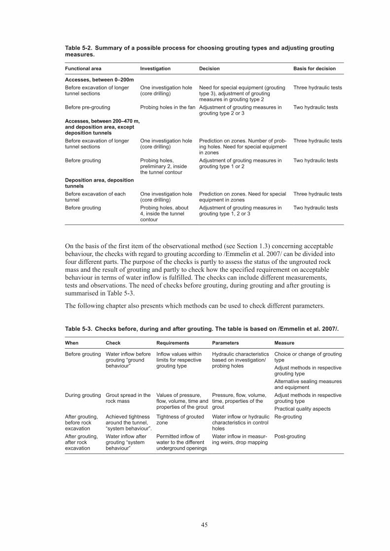
45
On the basis of the first item of the observational method (see Section 1.3) concerning acceptable behaviour, the checks with regard to grouting according to /Emmelin et al. 2007/ can be divided into four different parts. The purpose of the checks is partly to assess the status of the ungrouted rock mass and the result of grouting and partly to check how the specified requirement on acceptable behaviour in terms of water inflow is fulfilled. The checks can include different measurements, tests and observations. The need of checks before grouting, during grouting and after grouting is summarised in Table 5-3.
The following chapter also presents which methods can be used to check different parameters.
Table 5-2. Summary of a possible process for choosing grouting types and adjusting grouting measures.
Functional area Investigation Decision Basis for decision
Accesses, between 0–200mBefore excavation of longer tunnel sections
One investigation hole (core drilling)
Need for special equipment (grouting type 3), adjustment of grouting measures in grouting type 2
Three hydraulic tests
Before pre-grouting Probing holes in the fan Adjustment of grouting measures in grouting type 2 or 3
Two hydraulic tests
Accesses, between 200–470 m, and deposition area, except deposition tunnelsBefore excavation of longer tunnel sections
One investigation hole (core drilling)
Prediction on zones. Number of prob-ing holes. Need for special equipment in zones
Three hydraulic tests
Before grouting Probing holes, preliminary 2, inside the tunnel contour
Adjustment of grouting measures in grouting type 1 or 2
Two hydraulic tests
Deposition area, deposition tunnelsBefore excavation of each tunnel
One investigation hole (core drilling)
Prediction on zones. Need for special equipment in zones
Three hydraulic tests
Before grouting Probing holes, about 4, inside the tunnel contour
Adjustment of grouting measures in grouting type 1, 2 or 3
Two hydraulic tests
Table 5-3. Checks before, during and after grouting. The table is based on /Emmelin et al. 2007/.
When Check Requirements Parameters Measure
Before grouting Water inflow before grouting “ground behaviour”
Inflow values within limits for respective grouting type
Hydraulic characteristics based on investigation/ probing holes
Choice or change of grouting typeAdjust methods in respective grouting typeAlternative sealing measures and equipment
During grouting Grout spread in the rock mass
Values of pressure, flow, volume, time and properties of the grout
Pressure, flow, volume, time, properties of the grout
Adjust methods in respective grouting typePractical quality aspects
After grouting, before rock excavation
Achieved tightness around the tunnel, “system behaviour”.
Tightness of grouted zone
Water inflow or hydraulic characteristics in control holes
Re-grouting
After grouting, after rock excavation
Water inflow after grouting “system behaviour”
Permitted inflow of water to the different underground openings
Water inflow in measur-ing weirs, drop mapping
Post-grouting

46
5.5.2 Checks before groutingDifferent types of hydraulic tests can be made in investigation holes and probing holes, for example to determine transmissivity, assessment of the amount of water-bearing fractures, hydraulic fracture aperture, and groundwater pressure. Hydraulic tests can be made in a number of different ways (one or two packers, different packer spacing, number of pressure levels and testing time) or as flow logging.
One form of hydraulic tests is water loss measurements, a method that has been in use a long time. A generally accepted branch practice for carrying out such measuring is available (see for example /Eriksson and Stille 2005/). Even flow measuring and pressure build-up tests, are common methods in determining transmissivity in boreholes.
Modern drilling rigs normally feature automatic recording of drill parameters integrated with the rig. Post-processing and interpreting such parameters can be made. Based on these recorded parameters and calibration, an assessment can be made, for example of water flow and poor rock. The system gives no detailed information on individual fracture characteristics but could facilitate identification of deformation zones. However, the question remains at present of developing practical handling of this system, i.e. recording, processing and interpretation of information, and what decisions can immediately be taken on site. This type of system has been used at several underground projects in Sweden, and some efforts have also been made to use it for the execution of grouting works. However, no experiences with regard to grouting have yet been published.
5.5.3 Checks during groutingPressure, flow, volume and time should be recorded continuously during the grouting work. Which parameters that should be recorded and the degree of accuracy, depend on the grouting type used. To check that grouting in the respective grouting type is carried out using the correct grout and equipment, continual checks of the grout and equipment should be carried out.
The aim of the continual checks is mainly to test that the intended characteristics are achieved. For grouts that have low pH the mixing procedure is especially critical /Ranta-Korpi et al. 2007/. Proper working of the grouting equipment should normally be checked continually during the process.
Various test methods for cement-based grouts are described for example in /Eriksson and Stille 2005/. Tests are normally made of the rheological properties (viscosity, yield value), penetrability, curing (gain in strength), change of volume, and specific weight. Which tests are to be made depend for example on what requirements on various parameters are critical and on whether specific requirements are prescribed.
Grouts of the type silica sol are relatively new in the Swedish market and have been used in only a few projects in Sweden. One relevant test regarding the properties of silica sol is the cup test for checking of gel time.
There are several tests methods available to determine properties of grout. The methods have been used to a varying degree and most of the methods can be considered as accepted. Some of the test methods are however not standardised. Development of test methods is currently in progress in the framework of research projects at Chalmers (eg, /Axelsson 2006/) and KTH (eg, /Draganovic 2005/).
5.5.4 Checks after grouting, before rock excavationHydraulic tests can be made in control holes, drilled after a first grouting round, to check grouting results. Based on the results of these tests, subsequent decisions can be made regarding complementary grouting. Hydraulic tests are carried out in the same way as those before grouting.
5.5.5 Checks after grouting, after rock excavationInflow in different underground openings can be checked by collecting and measuring the inflow in measuring weirs, located at suitable places in the underground facility (see for example /Almén and Stenberg 2005/). To obtain accurate measurements it is necessary that the amount of process water applied can be measured or is known, which can be difficult in individual stretches of tunnel. Inflow can also be checked by collecting the inflow in pump sumps and measuring the total pumped out volume per unit of time.

47
Point leakage can also be checked, eg, by drop mapping. Drop mapping should be carried out in con-nection with rock mapping and can subsequently be repeated as required. Furthermore, the location of drop can be determined with the aid of photographs and/or laser scanning.
Considerable uncertainties are generally related to the results of inflow measurements in tunnels. This applies especially to results of measurements in the construction stage. A general opinion is that there is a need of development in methods for checking that specified requirements on tightness are fulfilled. Particular emphasis should be put on developing a method for measuring point leakage in deposition tunnels and deposition holes.
5.6 Specific of grouting measures for different grouting types, GrT
5.6.1 Grouting type 1GeneralGrouting type 1 implies that grouting need not be carried out or that only one grouting fan is made with a limited number of grouting holes or as a complete grouting fan, according to Figure 5-1. That a limited number of grouting holes should be sufficient is motivated by experience that discrete and individual fractures, if identified, are “easily” grouted. For grouting type 1 no further grouting is anticipated.
The functional areas and fracture domains/deformation zones that are anticipated as being in grouting type 1 are:• Ramp: in fracture domain FFM01 between the depth 200 to 470 m• Shafts in the central area and in fracture domain FFM01 between the depth 200 to 470 m• Rock caverns and tunnels in the central area (–470 m) in fracture domain FFM01• Main-, transport- and deposition tunnels at repository depth (–470m) and in fracture domain FFM01• Main- and transport tunnels in deformation zones with a low transmissivity• Shafts in the deposition area between the depth 200 to 470 m in fracture domain FFM01
Fan geometryThe grouting procedure begins by drilling probing holes. On the basis of results from probing holes and structure of the rock mass it is decided which grouting holes are to be drilled and grouted.
In a selective grouting fan there are greater possibilities to adapt the angles of holes in relation to the water-bearing fractures than in a complete fan with set hole spacing.
From the above way of reasoning, different base grouting fans are obtained for grouting type 1 depending on geometry of the individual underground openings.
GroutFor grouting type 1 mainly the cement based grout called “injection grout” and silica sol will probably be used.
Execution and equipmentHydraulic tests are made to determine fracture aperture for grouting type 1 and groundwater pressure. Based on the results of these tests decisions are made regarding type of grout, pressure and stop criteria.
For grouting type 1 the assumption is that no specific checks of sealing results such as control holes are necessary, except for the deposition tunnels. That the selective pre-grouting should be checked in the deposition tunnels is motivated by the fact that these tunnels are subject to stricter requirements on inflow of water than other areas. Control holes should be provided for all functional areas in extreme grouting scenarios, for example when large volumes of grout been injected before reaching the assessed grouting pressure.
48
5.6.2 Grouting type 2GeneralGrouting type 2 means that grouting is carried out as an initial pre-grouting with one or possibly two grouting rounds. At least one complete grouting fan is drilled and grouted, after which control holes are made to facilitate decision on possible new grouting rounds.
The functional areas and fracture domains/deformation zones that are anticipated as being in grouting type 2 are:
• Ramp: in fracture domain FFM01 between the depth 100 to 200 m
• Shafts in the central area or in the deposition area and in fracture domain FFM01 between the depth 100 to 200 m
• Under the depth 200 m when passing through deformation zones
• In parts of the ramp and shafts at the depth 0 to 100 m
Fan geometryOn the basis of the results from investigation holes or probing holes a complete grouting fan is drilled for grouting type 2, see Figure 5-1.
The grouting is made mainly at great depth and high pressure gradients. Erosion can occur in the grout at these high gradients /Emmelin et al. 2007/. To reduce the gradients and thus the risk of erosion, the grouting fan should include a number of grouting holes at the tunnel front and also have a clear overlap between two adjacent grouting fans, corresponding to one tunnel diameter.
Geometry of the fan is to be adapted to the part of the facility and if possible to the fracture structure.
GroutFor grouting type 2 the main choice is a cement-based grout for the first grouting round.
In a possible second grouting round, a cement-based grout or silica sol may be chosen depending on the result from control holes after the first grouting round.
For grouting type 2 mainly the cement based grouts called “injection grout” and “stop grout” will probably be used. Silica sol will be used for complementary grouting.
Execution and equipmentHydraulic tests are made in each grouting hole, mainly to enable assessment of fracture apertures and groundwater pressure and thereby identification of execution aspects and to enable a decision on which of the different SKB recipes should be selected according to principles in Table 4-7 and Table 4-8 respectively in Chapter 4.4. This implies that cement-based grouts and silica sol recipes can occur within the same grouting fan. This combination of grouts has been used with good results in grouting trials using silica sol, see Appendix A.
After grouting, a check of the result should be made using the control holes. Based on the result from the control holes a possible complementary grouting is then carried out, i.e. a second grouting round.
The grouting pump shall cope with both low flows and extremely high flows at high total pressure, which current equipment can not manage with one and the same pump. This implies that a pumping system including several pumps with different capacities must be connected together. The recording equipment must cope with the extreme measuring intervals that can be anticipated and possibly two parallel systems can be required to cover the extreme values and measuring accuracy.
Through larger deformation zones at repository depth it may be necessary with separate special grouting such as long-hole grouting that can require special equipment (see description of grouting type 3).
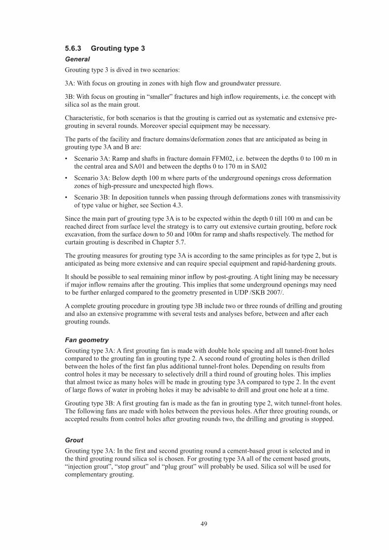
49
5.6.3 Grouting type 3GeneralGrouting type 3 is dived in two scenarios:
3A: With focus on grouting in zones with high flow and groundwater pressure.
3B: With focus on grouting in “smaller” fractures and high inflow requirements, i.e. the concept with silica sol as the main grout.
Characteristic, for both scenarios is that the grouting is carried out as systematic and extensive pre-grouting in several rounds. Moreover special equipment may be necessary.
The parts of the facility and fracture domains/deformation zones that are anticipated as being in grouting type 3A and B are:
• Scenario 3A: Ramp and shafts in fracture domain FFM02, i.e. between the depths 0 to 100 m in the central area and SA01 and between the depths 0 to 170 m in SA02
• Scenario 3A: Below depth 100 m where parts of the underground openings cross deformation zones of high-pressure and unexpected high flows.
• Scenario 3B: In deposition tunnels when passing through deformations zones with transmissivity of type value or higher, see Section 4.3.
Since the main part of grouting type 3A is to be expected within the depth 0 till 100 m and can be reached direct from surface level the strategy is to carry out extensive curtain grouting, before rock excavation, from the surface down to 50 and 100m for ramp and shafts respectively. The method for curtain grouting is described in Chapter 5.7.
The grouting measures for grouting type 3A is according to the same principles as for type 2, but is anticipated as being more extensive and can require special equipment and rapid-hardening grouts.
It should be possible to seal remaining minor inflow by post-grouting. A tight lining may be necessary if major inflow remains after the grouting. This implies that some underground openings may need to be further enlarged compared to the geometry presented in UDP /SKB 2007/.
A complete grouting procedure in grouting type 3B include two or three rounds of drilling and grouting and also an extensive programme with several tests and analyses before, between and after each grouting rounds.
Fan geometryGrouting type 3A: A first grouting fan is made with double hole spacing and all tunnel-front holes compared to the grouting fan in grouting type 2. A second round of grouting holes is then drilled between the holes of the first fan plus additional tunnel-front holes. Depending on results from control holes it may be necessary to selectively drill a third round of grouting holes. This implies that almost twice as many holes will be made in grouting type 3A compared to type 2. In the event of large flows of water in probing holes it may be advisable to drill and grout one hole at a time.
Grouting type 3B: A first grouting fan is made as the fan in grouting type 2, witch tunnel-front holes. The following fans are made with holes between the previous holes. After three grouting rounds, or accepted results from control holes after grouting rounds two, the drilling and grouting is stopped.
GroutGrouting type 3A: In the first and second grouting round a cement-based grout is selected and in the third grouting round silica sol is chosen. For grouting type 3A all of the cement based grouts, “injection grout”, “stop grout” and “plug grout” will probably be used. Silica sol will be used for complementary grouting.

50
A grout with focus on rapid hardening must also be tested and approved before grouting in grouting type 3A can begin. This type of grout may be needed in the event of large flows of water. For this purpose grouts based on polyurethane may be necessary.
Grouting type 3B: According to /Funehag 2009/, the choice of the grout in a grouting hole should be made to the following principle:
• Hydraulic aperture < 150 µm means a silica sol grout with different gel time
• Hydraulic aperture > 150 µm means a cement-based grout with low pH value
Execution and equipmentFor grouting type 3A and 3B, time must be allowed for detailed analyses of results from investigation holes, probing holes and control holes, and possibly of grouting work done earlier.
Grouting type 3A: In the case of large inflows from bore holes, grouting round 1 is grouted at once without any hydraulic tests. The aim is to inject large amounts of grout, i.e. the criteria are large amounts of grout and/or long grout injection times. Hydraulic tests are made in each grouting hole before grouting round 2.
After completed grouting in round two, control holes are made in which hydraulic tests are performed to check the tightness achieved. Based on the result from the control holes a possible complementary grouting is then carried out, i.e. a third grouting round. In the third grouting round it is assumed that a cement based grout or silica sol will be used. The grouting pressure, recipe, procedure and equipment for silica sol are the same as for grouting type 1.
Some special equipment and measures may be necessary in grouting type 3A, especially at great depth. Preparedness should be available for example for drilling extra-long grouting holes /Chang et al. 2005/ and also for grouting with rapid-hardening grout. In the event of anticipated large flows of water, drilling and grouting through Blow-Out-Preventors (BOP) should be considered whereby the flow of water from the boreholes can be controlled /Chang et al. 2005/ (see Figure 5-5). Furthermore, the large flows of water and the pressures in grouting type 3A require substantial pump capacities. In some cases, for grouting type 3A, freezing may be necessary as complement to grouting.
Grouting type 3B: A complete grouting fan includes, in addition to three rounds of drilling and grouting, an extensive programme with several tests and analyses, see more details in Appendix A:
1. Drilling and installation of packers.
2. Three types of hydraulic tests are to be made in all holes.
3. Analysis of the results from the hydraulic tests is to be made. The execution of the grouting for each individual borehole is to be decided.
4. Grouting of the first rounds of boreholes, with silica sol or cement grout.
5. Drilling the second rounds of boreholes.
6. Three hydraulic tests are to be carried out in boreholes of the second grouting rounds.
7. Analysis of results is to be done according to item 3 above.
8. Grouting is to be carried out in all boreholes according to item 4 above.
9. Possible drilling of the third run of boreholes, if ingress in the boreholes is greater than a critical value.
10. Hydraulic tests are to be carried out in the boreholes in the third rounds.
11. Grouting is to be carried out in all boreholes in the third and final rounds.
When carrying out grouting in grouting type 3B only one hole can be grouted with silica sol at a time, i.e. so-called batch grouting in one hole.
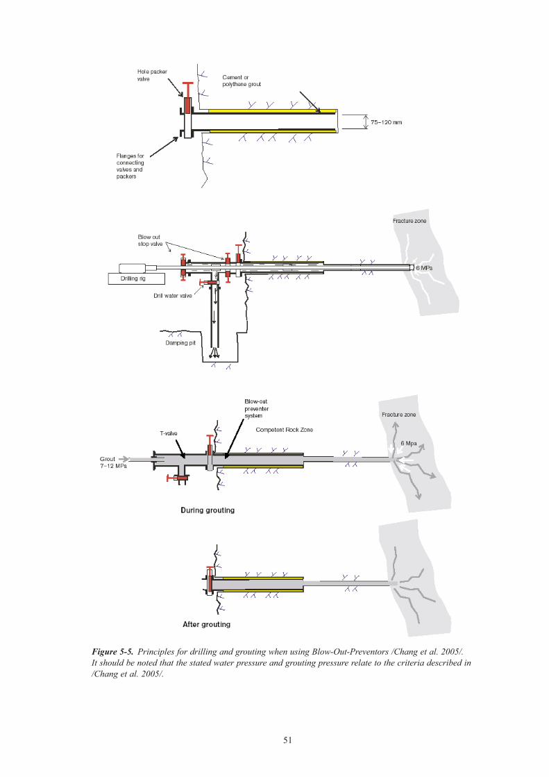
51
Figure 5-5. Principles for drilling and grouting when using Blow-Out-Preventors /Chang et al. 2005/. It should be noted that the stated water pressure and grouting pressure relate to the criteria described in /Chang et al. 2005/.
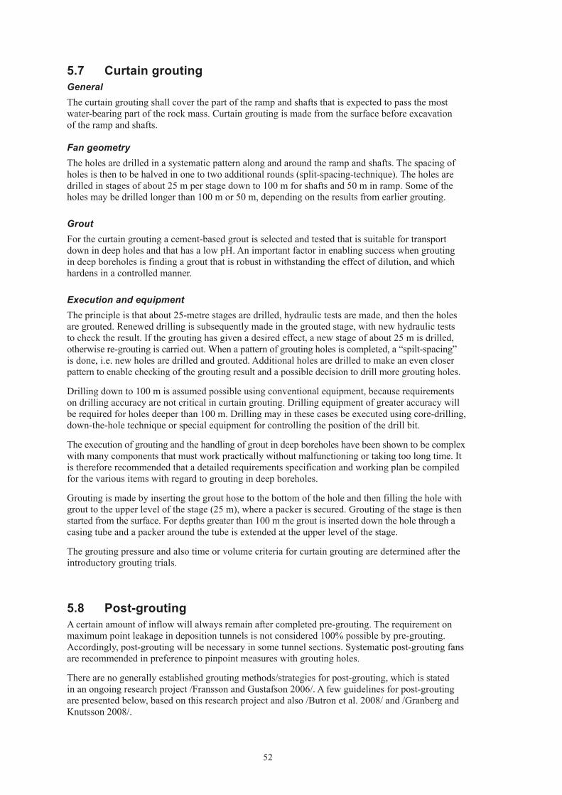
52
5.7 Curtain groutingGeneralThe curtain grouting shall cover the part of the ramp and shafts that is expected to pass the most water-bearing part of the rock mass. Curtain grouting is made from the surface before excavation of the ramp and shafts.
Fan geometryThe holes are drilled in a systematic pattern along and around the ramp and shafts. The spacing of holes is then to be halved in one to two additional rounds (split-spacing-technique). The holes are drilled in stages of about 25 m per stage down to 100 m for shafts and 50 m in ramp. Some of the holes may be drilled longer than 100 m or 50 m, depending on the results from earlier grouting.
GroutFor the curtain grouting a cement-based grout is selected and tested that is suitable for transport down in deep holes and that has a low pH. An important factor in enabling success when grouting in deep boreholes is finding a grout that is robust in withstanding the effect of dilution, and which hardens in a controlled manner.
Execution and equipmentThe principle is that about 25-metre stages are drilled, hydraulic tests are made, and then the holes are grouted. Renewed drilling is subsequently made in the grouted stage, with new hydraulic tests to check the result. If the grouting has given a desired effect, a new stage of about 25 m is drilled, otherwise re-grouting is carried out. When a pattern of grouting holes is completed, a “spilt-spacing” is done, i.e. new holes are drilled and grouted. Additional holes are drilled to make an even closer pattern to enable checking of the grouting result and a possible decision to drill more grouting holes.
Drilling down to 100 m is assumed possible using conventional equipment, because requirements on drilling accuracy are not critical in curtain grouting. Drilling equipment of greater accuracy will be required for holes deeper than 100 m. Drilling may in these cases be executed using core-drilling, down-the-hole technique or special equipment for controlling the position of the drill bit.
The execution of grouting and the handling of grout in deep boreholes have been shown to be complex with many components that must work practically without malfunctioning or taking too long time. It is therefore recommended that a detailed requirements specification and working plan be compiled for the various items with regard to grouting in deep boreholes.
Grouting is made by inserting the grout hose to the bottom of the hole and then filling the hole with grout to the upper level of the stage (25 m), where a packer is secured. Grouting of the stage is then started from the surface. For depths greater than 100 m the grout is inserted down the hole through a casing tube and a packer around the tube is extended at the upper level of the stage.
The grouting pressure and also time or volume criteria for curtain grouting are determined after the introductory grouting trials.
5.8 Post-groutingA certain amount of inflow will always remain after completed pre-grouting. The requirement on maximum point leakage in deposition tunnels is not considered 100% possible by pre-grouting. Accordingly, post-grouting will be necessary in some tunnel sections. Systematic post-grouting fans are recommended in preference to pinpoint measures with grouting holes.
There are no generally established grouting methods/strategies for post-grouting, which is stated in an ongoing research project /Fransson and Gustafson 2006/. A few guidelines for post-grouting are presented below, based on this research project and also /Butron et al. 2008/ and /Granberg and Knutsson 2008/.

53
Design of post-grouting must be created with regard to penetration of the grout, jacking effect, risk of surface leakage and also the pressure gradient and size/appearance of tunnel contour /Fransson and Gustafson 2006/. The gradient is considered first and foremost to prevent the grout from flowing back to the tunnel or that erosion of the grout occurs before it hardens. The execution and results of the pre-grouting is of considerable significance for design of the post-grouting.
When designing a post-grouting fan it is important to have knowledge of dip and strike direction of the water bearing fractures, based on tunnel mapping. This will facilitate the drilling of grouting holes into the fractures as accurately as possible at large angles. In describing fractures in connection with post-grouting design, consideration should be taken to whether the observed fractures are an effect of the tunnel blasting. Furthermore, probing holes are needed to assess fracture aperture and groundwater pressure before confirming the design.
In a case where the leakage comes from fractures that are not sealed due to geometry of the pre-grouting fan, i.e. have not been hit, a different angle should be used than that in the pre-grouting. This implies that the post-grouting fan should generally be orientated towards the tunnel driving and relatively at large angles to the tunnel contour. The reason for this is that fractures that have not been sealed are most often fairly gently dipping. Some overlapping between the holes should also be strived for, see Figure 5-6. In this scenario the grouting can be made in two grouting rounds, a first round with a cement-based grout and a second round with silica sol.
If fractures are not sealed because the grout does not have sufficient penetrability the fan geometry of the pre-grouting should be retained (unless gently dipping fractures dominate) and a different grout should be selected.
Precisely as in pre-grouting, the best penetration result is achieved by high-pressure, but particular attention must be paid in post-grouting to proximity of the tunnel contur. If the pressure used is too high there is a risk that wedges/blocks and possibly bolt reinforcement and sprayed concrete reinforcement will be damaged.
The guideline earlier has been that grouting holes for post-grouting should not be drilled further out than the sealed area of the pre-grouting. According to this guideline, the post-grouting has no effect outside this area. On the other hand, if a grout with good penetrability is used, eg, silica sol, longer post-grouting holes can be preferred to achieve better sealing results /Granberg and Knutsson 2008/. This is mainly because the pressure gradient often results in considerable surface leakage and a grout such as silica sol will flow out into the tunnel with practically no positive effect in the rock at all. Outside the pre-grouted zone the gradient is much smaller and the grout there penetrates further and has time to gel/harden and not flow out into the tunnel.
As in the case of pre-grouting, when grouting with silica sol it is essential that the grout is pumped until the gelling begins /Granberg and Knutsson 2008/.
Figure 5-6. Principles for post-grouting, in the scenario were the pre-grouting fan does not cross the water bearing fractures.


55
6 System behaviour
6.1 IntroductionThe assessment of inflow after grouting (in UDP /SKB 2007/ called “system behaviour”) is to be made for different functional areas based on calculations using analytical methods and/or experience from earlier grouting. A comparison between assessed inflow after grouting and the requirements that are prescribed with regard to permitted inflow is also to be made.
Calculations of possible inflow after grouting are already presented in Chapter 4.3 in connection with the assessment of the degree of difficulty for the grouting. These are also presented in Chapter 6.3 below, together with a comparison of calculated inflow before pre-grouting. A comparison between calculation results and experience of grouting is presented in Chapter 6.4.
6.2 Calculation methodsA description of the calculation methods is presented in Chapter 3.2, input data before grouting is described in Chapter 3.3, input data concerning the grouted zone is presented in Table 4-1 and transmissivity of the grouted zone in different cases is presented also in Table 4-1.
6.3 Calculation resultThe calculation of inflow after grouting is presented in Table 6-1. Table 6-1 also presents inflow before grouting calculated according to Chapter 3.
6.4 Comparison between calculation results and experience of grouting
Comparisons between calculations of water inflow after grouting and measured water inflow in other constructed underground facilities are associated with many uncertainties. Differences can exist for example in hydrogeological characteristics and groundwater pressure, geometry of the tunnels, require-ments on tightness and also grouting measures. Moreover, there are uncertainties with regard to accuracy of the calculation method.
Experience from grouting, which could be compared with the calculated inflow in Table 6-1 is available, for example from the construction of tunnels and rock caverns for SFR (see Appendix A) and also from two discharge tunnels from Forsmark 1-2 (2,300 m long) and Forsmark 3 (3,000 m long). These tunnels are situated in rock domains bordering on rock domain RFM029, in which most of the under-ground facility will be located.
Tunnels and rock caverns at SFR are situated down to 140 m depth and for the discharge tunnels the corresponding depth is about 70 m /Carlsson and Christiansson 2007/. In the tunnels made, water-bearing gently dipping fractures and deformation zones were found that required extensive grouting while the rock mass otherwise was relatively tight. Furthermore, individual vertical deformation zones with varying characteristics were passed and which in some cases required extensive grouting /SKB 2008a/.
The biggest proportion of water inflow in the ramp and shafts of the final repository are anticipated at the depth 0–100 m. Distributed along the length of the ramp and shafts in this depth interval the calculated maximum inflow after grouting will be, according to Table 4-3, between 100 and 127 l/min, 100 m.
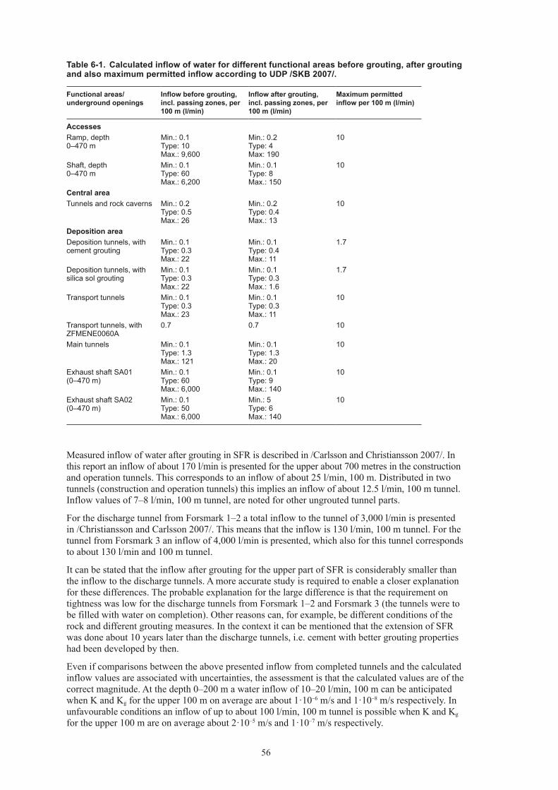
56
Measured inflow of water after grouting in SFR is described in /Carlsson and Christiansson 2007/. In this report an inflow of about 170 l/min is presented for the upper about 700 metres in the construction and operation tunnels. This corresponds to an inflow of about 25 l/min, 100 m. Distributed in two tunnels (construction and operation tunnels) this implies an inflow of about 12.5 l/min, 100 m tunnel. Inflow values of 7–8 l/min, 100 m tunnel, are noted for other ungrouted tunnel parts.
For the discharge tunnel from Forsmark 1–2 a total inflow to the tunnel of 3,000 l/min is presented in /Christiansson and Carlsson 2007/. This means that the inflow is 130 l/min, 100 m tunnel. For the tunnel from Forsmark 3 an inflow of 4,000 l/min is presented, which also for this tunnel corresponds to about 130 l/min and 100 m tunnel.
It can be stated that the inflow after grouting for the upper part of SFR is considerably smaller than the inflow to the discharge tunnels. A more accurate study is required to enable a closer explanation for these differences. The probable explanation for the large difference is that the requirement on tightness was low for the discharge tunnels from Forsmark 1–2 and Forsmark 3 (the tunnels were to be filled with water on completion). Other reasons can, for example, be different conditions of the rock and different grouting measures. In the context it can be mentioned that the extension of SFR was done about 10 years later than the discharge tunnels, i.e. cement with better grouting properties had been developed by then.
Even if comparisons between the above presented inflow from completed tunnels and the calculated inflow values are associated with uncertainties, the assessment is that the calculated values are of the correct magnitude. At the depth 0–200 m a water inflow of 10–20 l/min, 100 m can be anticipated when K and Kg for the upper 100 m on average are about 1·10–6 m/s and 1·10–8 m/s respectively. In unfavourable conditions an inflow of up to about 100 l/min, 100 m tunnel is possible when K and Kg for the upper 100 m are on average about 2·10–5 m/s and 1·10–7 m/s respectively.
Table 6-1. Calculated inflow of water for different functional areas before grouting, after grouting and also maximum permitted inflow according to UDP /SKB 2007/.
Functional areas/ underground openings
Inflow before grouting, incl. passing zones, per 100 m (l/min)
Inflow after grouting, incl. passing zones, per 100 m (l/min)
Maximum permitted inflow per 100 m (l/min)
AccessesRamp, depth 0–470 m
Min.: 0.1 Type: 10 Max.: 9,600
Min.: 0.2 Type: 4 Max: 190
10
Shaft, depth 0–470 m
Min.: 0.1 Type: 60 Max.: 6,200
Min.: 0.1 Type: 8 Max.: 150
10
Central areaTunnels and rock caverns Min.: 0.2
Type: 0.5 Max.: 26
Min.: 0.2 Type: 0.4 Max.: 13
10
Deposition areaDeposition tunnels, with cement grouting
Min.: 0.1 Type: 0.3 Max.: 22
Min.: 0.1 Type: 0.4 Max.: 11
1.7
Deposition tunnels, with silica sol grouting
Min.: 0.1 Type: 0.3 Max.: 22
Min.: 0.1 Type: 0.3 Max.: 1.6
1.7
Transport tunnels Min.: 0.1 Type: 0.3 Max.: 23
Min.: 0.1 Type: 0.3 Max.: 11
10
Transport tunnels, with ZFMENE0060A
0.7 0.7 10
Main tunnels Min.: 0.1 Type: 1.3 Max.: 121
Min.: 0.1 Type: 1.3 Max.: 20
10
Exhaust shaft SA01 (0–470 m)
Min.: 0.1 Type: 60 Max.: 6,000
Min.: 0.1 Type: 9 Max.: 140
10
Exhaust shaft SA02 (0–470 m)
Min.: 0.1 Type: 50 Max.: 6,000
Min.: 5 Type: 6 Max.: 140
10
57
6.5 ConclusionsBased on calculations made and comparisons with grouting carried out in the Forsmark area, the following conclusions can be drawn:
• Calculated inflow of water after grouting is considered reasonable and the values in Table 6-1 are to be viewed as an average inflow for a random 100 metre length.
• The largest proportion of the water inflow is anticipated in ramp and shafts down to 200 m depth and in the passage of certain deformation zones.
• In unfavourable conditions the inflow of water after grouting can exceed the requirement of maximum permitted inflow in ramp, shafts, transport/and main tunnels and also certain deposition tunnels. What too high inflow of water will give in consequence is discussed in Chapter 8.
• Especially the difficulty of meeting the requirement for the exhaust shafts should be considered, since grouting can only be carried out from the surface.


59
7 Compilation of materials and other resources
7.1 IntroductionAmounts with regard to grouting refer according to UDP /SKB 2007/ to amounts of the different materials that are included in proposed grouts and the number of boreholes. In design step D2 it is to be assumed that the grout provided by SKB can be used.
The degree of detail regarding presentation of amounts is that material is to be presented in m3 and tonne and also that the amounts are to be presented for accesses (ramp and shafts), central area and also the deposition areas.
Based on complementary requirements on presentation from SKB, it also applies that amounts are to be presented for the respective functional areas, i.e. deposition tunnels, central area, main and transport tunnels including exhaust shafts in deposition area and also ramp and shafts in the central area.
The assessment of the amounts of grout is presented in Chapter 7.2.
Even other resources, i.e. mainly equipment, are to be summarised according to UDP /SKB 2007/ (see Chapter 7.3). These resources and the application are also described in Chapter 5 in conjunction with the description of grouting types.
Lengths of different underground openings in the underground facility through fracture domains and deformation zones are based on the presented layout /Hansson et al. 2008/.
7.2 Amounts of groutFor the calculation of the amount it is stated in UDP /SKB 2007/ that it is to be based on the assumption that the porosity in the rock mass is filled with grout a certain length outside the tunnel periphery. The porosity is to be based on the hydrogeological properties that are presented in SER /SKB 2008a/ and the grout spread around the tunnel periphery is to be assumed as corresponding to the thickness of the grouted zone.
7.2.1 Calculation methodsCalculations of the volumes in the different underground openings have been made using Equation 7-1 (/Eriksson and Stille 2005/). Assessments of amounts based on this equation can according to /Eriksson and Stille 2005/ be adequate in a calculation phase. However, the importance of utilising experience from earlier grouting is emphasised.
To calculate the amount of grout remaining in the rock mass after blasting, the Equation 7-1 is modified according to Equation 7-2.
7-1
7-2
in which
V = injected volume (m3/m)
t = thickness of grouted zone (m)
rt = tunnel radius (m)
n = porosity (dimensionless)
( )2trtnV +⋅⋅= π
( )trttnV ⋅⋅+⋅⋅= 22π
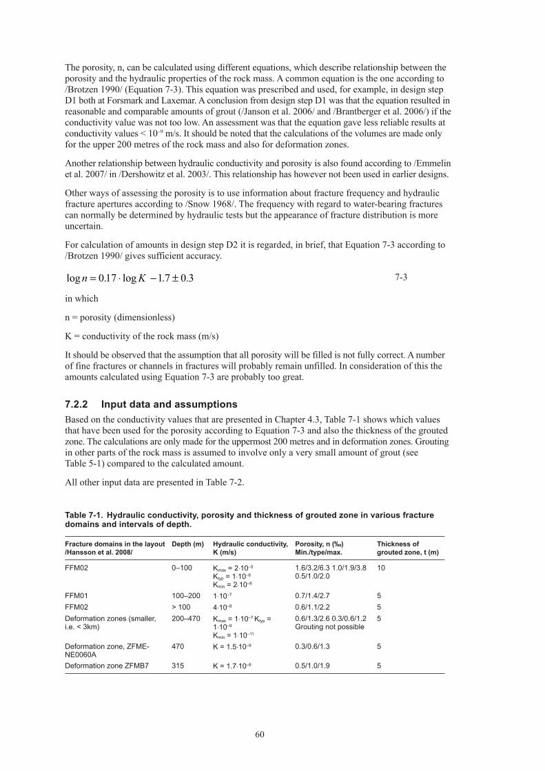
60
The porosity, n, can be calculated using different equations, which describe relationship between the porosity and the hydraulic properties of the rock mass. A common equation is the one according to /Brotzen 1990/ (Equation 7-3). This equation was prescribed and used, for example, in design step D1 both at Forsmark and Laxemar. A conclusion from design step D1 was that the equation resulted in reasonable and comparable amounts of grout (/Janson et al. 2006/ and /Brantberger et al. 2006/) if the conductivity value was not too low. An assessment was that the equation gave less reliable results at conductivity values < 10–9 m/s. It should be noted that the calculations of the volumes are made only for the upper 200 metres of the rock mass and also for deformation zones.
Another relationship between hydraulic conductivity and porosity is also found according to /Emmelin et al. 2007/ in /Dershowitz et al. 2003/. This relationship has however not been used in earlier designs.
Other ways of assessing the porosity is to use information about fracture frequency and hydraulic fracture apertures according to /Snow 1968/. The frequency with regard to water-bearing fractures can normally be determined by hydraulic tests but the appearance of fracture distribution is more uncertain.
For calculation of amounts in design step D2 it is regarded, in brief, that Equation 7-3 according to /Brotzen 1990/ gives sufficient accuracy.
7-3
in which
n = porosity (dimensionless)
K = conductivity of the rock mass (m/s)
It should be observed that the assumption that all porosity will be filled is not fully correct. A number of fine fractures or channels in fractures will probably remain unfilled. In consideration of this the amounts calculated using Equation 7-3 are probably too great.
7.2.2 Input data and assumptionsBased on the conductivity values that are presented in Chapter 4.3, Table 7-1 shows which values that have been used for the porosity according to Equation 7-3 and also the thickness of the grouted zone. The calculations are only made for the uppermost 200 metres and in deformation zones. Grouting in other parts of the rock mass is assumed to involve only a very small amount of grout (see Table 5-1) compared to the calculated amount.
All other input data are presented in Table 7-2.
Table 7-1. Hydraulic conductivity, porosity and thickness of grouted zone in various fracture domains and intervals of depth.
Fracture domains in the layout /Hansson et al. 2008/
Depth (m) Hydraulic conductivity, K (m/s)
Porosity, n (‰) Min./type/max.
Thickness of grouted zone, t (m)
FFM02 0–100 Kmax = 2⋅10–5
Ktyp = 1⋅10–6
Kmin = 2⋅10–8
1.6/3.2/6.3 1.0/1.9/3.8 0.5/1.0/2.0
10
FFM01 100–200 1⋅10–7 0.7/1.4/2.7 5FFM02 > 100 4⋅10–8 0.6/1.1/2.2 5Deformation zones (smaller, i.e. < 3km)
200–470 Kmax = 1⋅10–7 Ktyp = 1⋅10–9
Kmin = 1⋅10–11
0.6/1.3/2.6 0.3/0.6/1.2 Grouting not possible
5
Deformation zone, ZFME-NE0060A
470 K = 1.5⋅10–9 0.3/0.6/1.3 5
Deformation zone ZFMB7 315 K = 1.7⋅10–8 0.5/1.0/1.9 5
3.07.1log17.0log ±−⋅= Kn

61
7.2.3 Calculation resultsBased on calculations made, Table 7-3 presents a summarising assessment of amounts for different functional areas. The amount of grout presented refers to the total amount of grout including tunnel- front grouting, curtain grouting and post-grouting. Hole-filling in tight investigation and probing holes is not included. The amount of grout that remains in the rock mass after blasting is presented in Table 7-4. The amounts presented are rounded off to the nearest 10 m3.
Table 7-2. Input data for calculating grouting amounts. The dash (–) means that overlap is not relevant because grouting through zones is judged as being possible with one grouting fan (one or several rounds).
Deposition tunnels
Main and transport tunnels
Rock caverns
Shafts Ramp
Total number of holes including re-grouting and tunnel-face holes
45 pcs. 40 pcs 60 pcs Sink shafts: 40 pcs 0–100 m 25 pcs 100–200 mCurtain grouting, shaft, Average 1 m hole spacing
60 pcs 0–100 m 45 pcs 100–200 mCurtain grouting : 3 rows at 200 m, hole spacing 2.5m
Hole length 20 m 20 m 20 m 20 m 30 mOverlap – – – 4 m 6 m
Table 7-3. Summary of total amounts of grout injected before blasting for different functional areas. The dash (–) means that grouting is not possible except for individual fractures and that the amount of grout is small.
Functional areas/under-ground openings
Drilling, number/drilled metre (no./m)
Volume of grout Min./type/max. (m3)
Proportion plug grout/ stop grout/injection grout/silica sol (%)
Accesses (0 to –200m)Ramp 7,500/150,000
Curtain grouting: 240/12,000
400–1,590 (Kmin)650–2,570 (Ktyp)980–3,910 (Kmax)
20/10/50/2020/30/40/1030/50/10/10
Shaft (4 shafts) 160/32,000Curtain grouting: 60/6,000
130–520 (Kmin)220–860 (Ktyp)330–1,310 (Kmax)
20/10/50/2020/30/40/1030/50/10/10
Central area (–470m)Rock caverns (grouting in deformation zones)
300/6,000 – (Kmin)20–60 (Ktyp)30–140 (Kmax)
–10/10/50/3010/20/50/20
Deposition area (–470m)Deposition tunnels (grout-ing in deformation zones, with silica sol concept)
11,800/235,800 – (Kmin)270–1,090 (Ktyp)600–2,380 (Kmax)
–10/20/20/5010/20/20/50
Transport tunnels (grout-ing in deformation zones, including ZFMENE0060A)
960/19,200 – (Kmin)35–140 (Ktyp)80–280 (Kmax)
–10/20/50/2010/20/50/20
Main tunnels (grouting in deformation zones)
4,400/88,000 – (Kmin)170–660 (Ktyp)360–1,440 (Kmax)
–10/20/50/2010/20/50/20
Exhaust shaft SA01 (including ZFMB7)
Curtain grouting:10/3,000
30–130 (Kmin)50–210 (Ktyp)80–330 (Kmax)
–/10/70/2010/40/30/1010/50/10/10
Exhaust shaft SA02 Curtain grouting:10/2,000
30–110 (Kmin)50–190 (Ktyp)70–290 (Kmax)
–/10/60/3010/30/40/2010/50/20/20

62
The proportions of different grouts are assessed based on the following presumptions:
• “Plug grout” is used for grouting of large fractures, which is anticipated mainly at depth 0–100 m in FFM02. For less permeable rock the amount of grout is judged to be smaller.
• “Stop grout” is anticipated for grouting, eg, a first grouting round in rock mass of high hydraulic conductivity.
• “Injection grout” is the grout that is used primarily, in rock mass of low hydraulic conductivity.
• Silica sol is used for complementary grouting where cement is not sufficient to satisfy tightness requirements and also for post-grouting. In more finely fractured rock and for stricter requirements on inflow, i.e. deposition tunnels, the proportion of silica sol is assumed to be greater than in more permeable rock and in other functional areas respectively.
Based on the assessed proportion of the different grouts, the amount of sub-material included can be calculated based on recipes of the individual grouts.
Table 7-5 present the estimated tunnel lengths with and without grouting, in respective functional areas, and also the grout take, based on Table 7-3.
Based on Table 7-4 and recipes in Appendix C the amount of grout materials are estimated for ramp/shaft, central area and deposition area in Table 7-6.
Table 7-4. Summary of amounts of grout remaining in the rock mass after blasting for different functional areas. The dash (–) means that grouting is not possible except for individual fractures and that the amount of grout is small.
Functional areas/ underground openings
Drilling, number/ drilled metre (no./m)
Volume of grout Min./type/max. (m3)
Proportion plug grout/ stop grout/injection grout/silica sol (%)
Accesses (0 to –200m)Ramp 7500/150,000
Curtain grouting: 240/12,000
370–1,460 (Kmin)600–2,380 (Ktyp)920–3,650 (Kmax)
20/10/50/2020/30/40/1030/50/10/10
Shaft (4 shafts)
160/32,000Curtain grouting: 60/6,000
120–500 (Kmin)210–820 (Ktyp)320–1,270 (Kmax)
20/10/50/2020/30/40/1030/50/10/10
Central area (–470m)Rock caverns (grouting in deformation zones)
300/6,000 – (Kmin)10–30 (Ktyp)20–90 (Kmax)
–10/10/50/3010/20/50/20
Deposition area (–470m)Deposition tunnels (grouting in deformation zones with silica sol concept)
11800/235,800 – (Kmin)240–980 (Ktyp)540–2,110 (Kmax)
–10/20/20/5010/20/20/50
Transport tunnels (grouting in deformation zones, including ZFMENE0060A)
960/19,200 – (Kmin)30–110 (Ktyp)65–250 (Kmax)
–10/20/50/2010/20/50/20
Main tunnels (grouting in deformation zones)
4400/88,000 – (Kmin)135–530 (Ktyp)290–1,170 (Kmax)
–10/20/50/2010/20/50/20
Exhaust shaft SA01 (including ZFMB7)
Curtain grouting:10/3,000
30–120 (Kmin)50–200 (Ktyp)80–320 (Kmax)
–/10/70/2010/40/30/1010/50/10/10
Exhaust shaft SA02 Curtain grouting:10/2,000
30–100 (Kmin)50–180 (Ktyp)70–280 (Kmax)
–/10/60/3010/30/40/2010/50/20/20
Kmin, Ktyp and Kmax represent intervals in hydraulic characteristics according to SER /SKB 2008a/. Type values refer to the value that has been judged as most probable in the interval between maximum and minimum.

63
Table 7-5. Estimated lengths with and without grouting and grout take.
Functional areas/underground openings
Length (m)
Grout take (m3/m)
AccessesRamp, 0–100 m 1,000 0.5–2.0Ramp, 100–200 m 1,000 0.15–0.55Ramp, > 200 m, no grouting 2,700 –Shafts, 0–100 m 100 0.45–1.7Shafts, 100–200 m 100 0.1–0.4Shafts, > 200 m, no grouting 270 –Deposition areaDeposition tunnels 5,250 0.05–0.2Deposition tunnels, no grouting 55,800 –Transport tunnels 400 0.08–0.3Transport tunnels, no grouting 4,500 –Main tunnels 2,200 0.08–0.3Main tunnels, no groting 4,500 –
Table 7-6. Estimated quantities of grout materials and drilling that remain in the rock mass after excavation of the different underground openings.
Element Material Ramp/Shafts [ton] 1) 2 ) Central Area [ton] 1) Deposition Area [ton] 1)
min max min max min max
Cement grouting
Water 350 1,360 3 10 110 440Portland 3) 330 1,310 3 8 100 400Silica Fume 4) 460 1,790 4 11 140 550Super Plasticiser 5) 23 90 0.2 0.5 7 30
Chemical grouting
Silica 105 410 3 9 160 640NaCl solution 21 85 0.6 2 30 130
Volume of grout [m3] 910 3,580 10 30 405 1,620
Drilling Number of holes 7,980 pcs 300 pcs 17,160 pcsDrilling meter 205,000 m 6,000 m 343,000 m
1) Based on ”type” hydraulic conditions (Ktyp) in Table 7-4.2) Incl. the Exhaust shafts SA01 and SA02.3) Sulphate resistant Ordinary Portland cement with d95 on 16 µm, type Ultrafin 16 or equivalent, see Appendix C.4) Dispersed silica fume, microsilica with d90 = 1 µm type GroutAid or equivalent. The density is to be between 1,350–1,410 kg/m3 and 50% ±2% of the solution is to consist of solid particles, see Appendix C.5) Super plasticiser, naphthalene-sulphonate based, density about 120 kg/m3, type SIKA Melcrete, see Appendix C.

64
7.2.4 Comparison between calculated amounts and experience of groutingComparisons are made between the estimated amounts of grout and the amounts used in underground facilities constructed earlier, to verify the amounts calculated, but the comparisons involve considerable uncertainties. Differences can exist for example in the hydrogeological characteristics and groundwater pressure, geometry of the tunnels, requirements on tightness and also grouting measures.
Experience from grouting, which could be compared with the calculated amounts in Table 7-3 is available, for example from the construction of SFR (see Appendix A) and also from two discharge tunnels from Forsmark 1-2 and Forsmark 3 (see Chapter 6.4).
A considerable amount of the grouting in the construction of SFR was made in connection with the Singö zone and also the gently dipping water-bearing zone, designated H2, which was encountered in the lower building tunnel at SFR.
In connection with zone H2 the average hydraulic conductivity was about 1–2·10–6 m/s and for the Singö zone values of 2·10–8–1·10–6 m/s were noted for parts of the zone /Carlsson et al. 1987/.
According to /Carlsson et al. 1987/ the amount of injection cement for this grouting was 44,550 kg distributed in 361 boreholes. With an average length of borehole at 15 m the amount injected would be about 8 kg cement per drilled metre, including grout hole volume. The corresponding amount for the Singö zone was 7.5 kg cement per drilled metre.
These amounts of grout can be compared to the amounts calculated for the ramp in the type case, i.e. Ktyp, before the blasting. In this case the initial conductivity is in the range of 1·10–6–1·10–7 m/s down to a depth of 200 m.
Table 7-3 gives the amount of grout in m3 which is to be converted to kg cement or bonding agent, depending on the recipe. Based on the recipes for the grouts that have been provided by SKB an average value for the proportion of bonding agent (cement plus silica) is assumed at 750 kg/m3 of grout. The calculated volumes before blasting according to Table 7-3 correspond according to this assumption to about 3–12 kg bonding agent per drilled metre, which is in the same size range as the amounts injected at SFR. It should however be noted that the cement-based grouts that are presumed for use in the final repository do not have the same composition as those used at SFR. The grouts that have been provided by SKB for design step D2 contain, for example, a larger proportion silica and a smaller proportion cement than the grout used at SFR. Furthermore, the ratio of water to cement plus silica is lower than the water cement ratio practised at SFR. There are also differences with regard to the number of boreholes. In an assessment of plausibility concerning the estimated amounts it is however considered that the comparison is sufficiently accurate, despite the differences in the grouts.
For the more water-bearing parts of the rock mass at depth 0–100 m in FFM01, estimated amounts of cement up to about 20 kg per drilled metre are obtained in the same way. These amounts are also considered reasonable on the basis of experience of grouting in water-bearing zones. In /Carlsson and Christiansson 2007/ a cement quantity of about 27 kg per drilled metre is stated for the discharge tunnel from Forsmark 3 for grouting in water-bearing deformation zones. Furthermore, it can be noted in Appendix A that a water-bearing zone was grouted in investigation hole KFM01A at the depth of about 150 m. The thickness of the zone was estimated at about 10 m, indicating a consumption of injection cement at about 50 kg per drilled metre.
Documented experience is also available concerning the driving of Äspö HRL (/Stille et al. 1993/ and /Stille et al. 1994/). The anticipated grouting scenario in Forsmark does not however correspond to the documented experience in Äspö HRL. The grouting in Äspö HRL was done partly in a few extremely water-bearing deformation zones at a depth under 100 m and partly by selective grouting in water-bearing discrete fractures between the deformation zones. The grouting in the deformation zones was very extensive and time-consuming. For example about 86 m3 of grout and about 3 months work was needed before one of the zones could be passed; and despite this large inflow of water remained. Grouting in the discrete fractures was made with a full grouting fan, following a decision based on results in investigation holes. A few grouting holes were injected with large amounts of grout, up to a maximum of about 8,600 l. Accordingly, the average amount of grout when grouting water-bearing fractures with a high transmissivity was high, about 26 l per drilled metre (or about 35 kg per drilled metre).
In brief, the opinion is that the estimated amounts of grout are in the correct range of magnitude in comparison with groutings performed earlier.

65
7.2.5 ConclusionsIn Table 7-3 it can be seen that large amounts of grout can be anticipated in the ramp and the shafts in the upper 200 metres. The difference between estimated maximum and minimum amounts is however considerable (about a factor of ten). This reflects the uncertainty about the conditions that will be met in tunnel excavation and grouting. This implies that test grouting should be carried out in a preliminary phase and an updating of grouting measures and estimations of amounts should be done as the tunnel excavation and grouting progresses. As mentioned earlier, the anticipated grouting at depth 0–100 m will be very extensive and therefore time-consuming.
Moreover, it should be observed that the calculation methods that have been used include considerable uncertainty. For example, the relationship between hydraulic conductivity and porosity is much discussed, for example low conductivities (about 1·10–9 m/s or lower) give too high porosity and consequently too high grout volume /Janson, et al. 2006/. It is also difficult to assess how much of the porosity around the rock mass is filled with grout, possibly not all, and also the actual grout spread, possible longer in the zones.
In comparison with the amounts of grout that are presented in design step D1 (see /Brantberger et al. 2006/) it can be stated that the amount of grout has increased in design step D2. This can be partly explained in that several deformation zones are passed in layout D2 compared to layout D1. Moreover, the assessment of grouting amounts for ramp and shafts has been done somewhat differently in design step D2 compared to D1. In design step D2 consideration has been taken to the fact that the rock mass can be severely water-bearing along long stretches while in design step D1 it was assumed that the grouting was limited to a few individual more water-bearing fracture zones.
7.3 Equipment summaryGrouting in the final repository is anticipated in a variety of conditions and with different requirements on tightness. Grouting will for example be carried out at great depth and at potentially high water pressure, a number of water-bearing fracture zones will probably be passed, grouting must be carried out from the surface down to several hundred metres depth and relatively unproven grouts will be used. These different grouting scenarios impose requirements on adapted equipment and skill in its use. Procurement of these resources must be ensured in good time before the construction starts since access to them can be limited.
In Chapter 5.8 the need of different equipment is described to a varying degree in connection with the description of grouting measures. The following list has been compiled of the special equipment that is anticipated for the grouting work.
On the basis of the grouting design work, the need of equipment required is listed below.• Drilling equipment for the drilling of boreholes from the surfaced down to 470 m depth (maximum
borehole deviation 0.5%)• Grouting equipment adapted for grouting in deep boreholes (eg, packers, casing tubes, device for
pressing the grouting to the bottom of the hole)• Grouting equipment adapted for grouts based on silica sol and for more than one hole grouting• Grouting equipment adapted for cement-based grouts with low pH and for more than one hole
grouting• Grouting pumps for both low flows and extremely high flows at high-pressure• Mixing equipment of high capacity• Recording equipment for both low flows and extremely high flows• Equipment that enables venting of grouting holes• Equipment for rapid-hardening grout• Equipment for measuring/confirmation of tightness conditions at about 1·10–9 m/s• Packers, hoses and connections for high pressure

67
8 Overall judgement of feasibility and uncertainty
8.1 GeneralIn the purpose (see Chapter 1.2) it is expressed that the design with regard to grouting shall:• Show that technique is available which, in anticipated conditions at the relevant site, can satisfy
stipulated requirements.• Estimate the amounts of grout and other resources that are needed.
Centred on these two items the feasibility and uncertainties have been discussed earlier in the report. On the basis of assessments concerning feasibility and uncertainties a risk list has been compiled in parallel with the grouting design work. The risk list constitutes a basis for the technical risk assessment, which is made in a separate design activity and is presented in a separate report according to UDP /SKB 2007/.
The implementation and uncertainty aspects that have appeared during the grouting design work and which are linked to the two items listed above are summarised as follows:• Fulfilment of tightness requirement and whether the requirement is to be interpreted per functional
area or a random 100 m length of an individual underground opening• Grouting of the uppermost 100 m rock mass, especially the curtain grouting• Grouting in deep boreholes, i.e. deeper than 100 m• Fulfilment of tightness requirement in deposition tunnel with relatively unproven technique, i.e.
the grouting measure mainly based on silica sol• SKB’s grouts (cement-based grouts of low pH and silica sol)• Robustness of control measures for decision between grouting types• Preparedness for unexpected events• Preparedness for alternative sealing measures – lining and freezing• Grouting measures and events that require special skills/equipment• Post-grouting, sealing of point leakage• Forecast of inflow• Equipment for Blow-Out-Preventors (BOP)• Quantity of grout
The above items are divided into two groups, i.e. those that are more linked to grouting measures and those that are linked to calculations.
8.2 Grouting measuresIn assessing plausibility with regard to the proposed grouting measures it should be observed according to Chapter 1.3 that:• The grouting measures are to be realistic in relation to current know-how and experience.• The grouting measures are to be robust in relation to anticipated variations in characteristics of
the rock mass.• A process for handling prevailing uncertainties should be presented.
Briefly, it is assumed possible to carry out grouting of the relevant site so that prescribed requirement on tightness is fulfilled in most of the facility. The work of grouting in some cases will be difficult and in the most unfavourable conditions there is risk that the tightness requirement will not be fulfilled in certain areas. This risk is assessed as greatest with regard to ramp and shafts to the central area, for exhaust shafts in the deposition area and when deposition tunnels intersect deformation zones. The risk is described further in forthcoming sections.

68
The grouting measures described are considered realistic although some methods involve relatively unproven technique, i.e. silica sol, and other less proven and documented methods such as grouting in deep boreholes.
With regard to the aim of robust measures, cement-based grouting, being a proven technique, can be used for most of the grouting work except for deposition tunnels. The three cement-based grouts that are provided by SKB are assessed as adequate for the different conditions that can be anticipated. Silica sol grouting is considered mainly for use in complementary pre-grouting and post-grouting. In the compilation of grouting measures a large amount of experience from earlier conducted grouting has been studied to support the choice of grouting measures. This has also been done to verify that the grouting measures are realistic and feasible.
A process for handling prevailing uncertainties has been described. The process includes principles for choosing and adjusting grouting measures together with checks, criteria and possible measures for different stages during construction.
Special aspects concerning feasibility and uncertainties are described below in more detail with regard to the grouting measures.• Fulfilment of tightness requirement and whether the requirement is to be interpreted per functional
area or a random 100 m length of an individual underground opening
In order to verify the fulfilment of the tightness requirements different checks are to be made. One of these checks includes hydraulic tests in control holes. However, there is uncertainty in the measuring accuracy for normal measuring methods at 1·10–9 m/s.
The assessment of whether the requirements on tightness can be fulfilled using present grouting technique is that they probably can not be fulfilled in the uppermost 100 metres of the rock mass or in passages of individual deformation zones of high transmissivity. Depending on the extent and result of the curtain grouting the probability may decrease.
Uncertainties also exist about whether the requirement on inflow will be fulfilled for the exhaust shafts for which grouting can only be made from the surface. The exhaust shafts could be done, as an alternative, by shaft sinking (like the skip shaft according to Chapter 5.3.2) which is a more robust method to fulfil the tightness requirement.
For certain deposition tunnels, which pass several deformation zones of high transmissivity, there is also a risk that the tightness requirement cannot be fulfilled. In most of the cases it is however assessed that post-grouting with silica sol will be able to reduce the inflow to acceptable levels. However, in individual deposition tunnels a greater inflow than that permitted can be the case. It should be noticed that a large part of the deformation zones is relatively tight. These observations imply that many deformation zones will have no need or a reduced need of grouting.
The inflow of water in the main tunnels and transport tunnels is mainly related to passage through deformation zones. In the layout work /Hansson et al. 2008/ a large part of two main tunnels has been placed along deformation zones, see Figure 2-5 and tunnels DB and DC. This has been done to avoid deformation zones in deposition tunnels and thereby utilise the tunnels for additional deposition holes and also cope with the stricter requirements on inflow in deposition tunnels. For these main tunnels an altered geometry of the grouting fan may be needed to achieve an acceptable sealing result.
The definition of the inflow requirement, i.e. whether the requirement applies to an entire functional area or for a random 100 metre stretch, affects the probability of fulfilling the requirement and the degree of difficulty for grouting. For example, if the requirement applies to the entire length of the ramp the tightness requirement will probably be fulfilled, but if it applies to a random 100 metre stretch the requirement will probably not be fulfilled for the uppermost parts.• Grouting of the uppermost 100 m rock mass, especially the curtain grouting
For ramp (0–50 m) and shafts (0–100 m) an introductory large-scale curtain grouting is proposed. The aim of the curtain grouting should be to reduce conductivity of the rock mass by about a factor of 10 and thereby reduce the degree of difficulty for example in excavating the ramp. The experience that is available concerning this issue is that grouting in boreholes down to a depth of about 100 m is feasible and manageable. The difficulty in Forsmark is the local extremely water-bearing horizontal

69
structures that could cause flushing and diluting of grout. It is however uncertain how difficult the grouting will be in the upper 100 metres of the rock mass. The hydraulic properties that are presented in SER /SKB 2008a/ imply that very large flows of water can be anticipated; giving rise to considerable grouting. At the same time, experience from other tunnels in the Forsmark area does not indicate any severe difficulties in tunnel excavation and grouting at the depth 0–100 m except in certain individual deformation zones (see SER /SKB 2008a/ and /Carlsson and Christiansson 2007/). Since the conditions in the upper part of the rock mass can vary from place to place, test groutings should therefore be carried out in the actual positions for ramp and shafts. During these test groutings the risk of grout spread to the ground surface and possibly to the cooling canal should be evaluated.• Grouting in deep boreholes, i.e. deeper than 100 m
The difficulty and uncertainties involved with grouting in deep boreholes concerns mainly practical problems such as transporting the grout down, how it is to be injected, and also when boring up can begin. To handle these uncertainties the recommendation is to compile detailed method statements of the execution, material and equipment. Test drillings and grouting trials should also be carried out.• Fulfilment of tightness requirement in deposition tunnels with relatively unproven technique, i.e.
grouting mainly based on silica sol
To fulfil the requirement in this case it is required that the tightness in a deformation zone in many scenarios must correspond to a hydraulic conductivity for the grouted zone at 1·10–9 m/s. Such grouting is judged to be difficult and has not been reported when using cement-based grouts. However, grouting trials at considerable depth using silica sol, as the main grout, and cement based grout in only larger fractures have been made under the auspices of SKB to test execution and sealing result, see Appendix A.
By using this new grouting concept with silica sol as the main grout in several grouting rounds /Funehag 2009/ supported by hydraulic tests in probing and control holes the opinion is that this tightness can be achieved.
This grouting measure has accordingly not been tested in conventional and rational grouting procedure.• SKB’s grouts (cement-based grouts and silica sol)
The different grouts that SKB provided for design step D2, i.e. three cement-based grouts of low pH and one silica sol based, are all relatively unproven. Grouting using cement-based grouts has been carried out a long time both in Sweden and abroad. Grouting with low pH-grouts using conventional mixing equipment is however not commonly practiced. Grouting is at present in progress in Finland using these grouts, where following up is carried out by Posiva.
With regard to silica sol grout the uncertainties refer to shrinkage, after the grout has hardened, at unsaturated conditions /Axelsson 2006/ and its long-term durability, i.e. > 5 years, which is unknown.• Robustness of control measures for decision between grouting types
The outcome of the grouting (sealing result and resources) might be very different depending on the decided level for “high enough certainty” when choosing between grouting types.
One uncertainty in this is judging a reasonable number of investigation and probing holes and also by which methods water-bearing deformation zones and fractures of various transmissivity values is identifiable.
The total number of holes has been assessed preliminary to at least three to five and that the zones are identified mainly by drill cores from the investigation holes and hydraulic tests in all the holes. The exact number of holes and what methods are to be used must be verified in the introductory grouting and possibly adjusted depending on results and site experience. Various statistical methods may also be used to derive the optimum number of holes. Such methods are not yet in practice but development is ongoing.• Preparedness for unexpected events
It is generally difficult to know what unexpected events can be anticipated during the construction stage. Moreover, individual interpretations of what is an unexpected event are very varied. An unexpected event during the construction stage can for example be flooding in sink shaft, large consumption of grout, need of freezing to control water inflow to the ramp, hardening of grout in equipment and unexpected leakage paths. In preparation for the grouting work an initial prepared-ness plan, including decision process and organisation, should be drawn up for unexpected events.

70
Preparedness should be available, for example, for more time-consuming and extensive grouting, several grouting rounds, an increased use of silica sol and special equipment, eg, BOP (Blow-Out-Preventor). Various measures and criteria for these should be formulated according to the principles for the observational method.
• Preparedness for alternative sealing measures – lining and freezing
It is uncertain whether the requirement on tightness can be fulfilled using known grouting methods for ramp and shafts for the uppermost 100 metres of the rock mass, the exhaust shafts, and limited stretches through deformation zones at repository depth. If the inflow of water cannot be accepted, should a technical solution be available to build a tight lining in the most water-bearing sections. This measure implies considerable cost and delays and also requires specific technical skills. Furthermore, the linings can have different appearances and be made in different ways depending on whether ramp or shafts are involved. A lining implies new questions, such as criteria for construction of a lining, extent of lining, technical aspects, geometries, tunnel excavation, costs and time for construction. It is therefore recommended that a separate survey is made concerning this issue.
To enable passage of certain water-bearing parts of the ramp for example, freezing may be a complement to grouting. Freezing of water-bearing zones is described in /Chang et al. 2005/• Grouting measures and events that require special equipment/know-how
The prescribed grouting measures require special equipment in certain cases and relevant know-how. Examples of such equipment are those for controlled drilling, various types of packers, equipment for grouting in deep boreholes and also pumps for varying pressure and flows. The access to this type of equipment is probably limited in the Swedish market. An important part of planning for the construction stage is therefore to allow time for planning, procurement and training with regard to various special equipment that are considered necessary.• Post-grouting, sealing of point leakage
Post-grouting is a measure that is necessary if the requirements are not fulfilled by pre-grouting. It is well known that succeeding with post-grouting is difficult and that the work demands both planning and thorough execution and also time. There are no established and reliable strategies for post-grouting. There is great need for development and several development projects are in progress both within and outside the SKB organisation.
8.3 Calculations• Forecast of inflow
Forecasts of inflow water include many sources of error. The calculation models that have been used in design step D2 are well known and accepted but they imply considerable simplification of reality. Furthermore, there may be uncertainties in input data from SER /SKB 2008a/, such as interpretations of measurement results, sampling tests within a wide range and calculation models.
The strategy should be to make more forecasts that are based on different calculation models and then make a total appraisal of the different forecasts together with engineering assessments. Before the construction stage begins a program for measuring the inflow should be compiled in which the forecast is verified and updated in steps with new knowledge about details.• Quantity of grout
Calculations of grouting amounts are also based on substantial simplifications. Furthermore, input data is based on the hydrological properties which also include many simplifications and uncertainties. Better calculation models exist (see for example /Eriksson and Stille 2005/, /Funehag 2007/ and /Stille and Andersson 2008/), but these require knowledge of details and also that analysis of grouting is made on site. Despite an increased knowledge of details with the more refined calculation methods, even here there is a need for adjustment of models based on results from grouting.
71
9 Continued design
According to UDP /SKB 2007/ design step D2 is the last design step in connection with the site investigations. After the site investigation stage a detailed design will follow according to /Emmelin et al. 2007/.
The strategy for detailed design should be a step-wise design, which is also evident in /Emmelin et al. 2007/. No detail solutions should be confirmed before more experience is available from grouting trials and from actual grouting in earlier excavated areas. The following work procedure is recommended:
1. Update the site criteria if more detailed investigations have been carried out
2. Detailed planning, strategy, execution including documentation and also analysis of test grouting from the surface
3. Design and implementation of large-scale curtain grouting, based on experience and analyses of trial grouting
4. Grouting of the shafts and the uppermost 100 m of the ramp to be designed, and implemented after analyses of the curtain grouting
5. Continued design and implementation of grouting in the ramp based on experience from earlier grouting
6. With experience from a large part of the ramp, the grouting of the central area and the various underground openings in the deposition area is to be planned and implemented
With this work procedure, more detailed criteria can be successively confirmed regarding grouting measures, such as criteria for selection of grouting type, adjustment of measures in a grouting type, when a second grouting round is to be made, and so on.
Parallel with the continued design, enquiries should also be made as to the need of development concerning available grouts and equipment, strategies and methods for post-grouting and also the extent and implementation of a possible lining or freezing.

73
10 References
Almén K-E, Stenberg L, 2005. Äspö Hard Rock Laboratory – Characterisation methods and instru-ments, Experience from the construction phase. SKB, Technical Report TR-05-11, December 2005.
Axelsson M, 2006. Strength Criteria on Grouting Agents for Hard Rock Laboratory studies performed on gelling liquid and cementitious grout. Geologiska institutionen, Chalmers tekniska högskola, Göteborg.
Bergman S G A, Nord G, 1982. Täta tunnlar lagom. BeFo Nr 64:1/82. Stockholm.
Brantberger M, Zetterqvist A, Arnbjerg-Nielsen T, Olsson T, Outters N, Syrjänen P, 2006. Final repository for spent nuclear fuel, Underground design Forsmark, Layout D1 SKB R-06-34, Svensk Kärnbränslehantering AB.
Brotzen O, 1990. The study of relevant and essential flowpaths. Symp. on validation of geospehere flow and transport models. Stockholm ISBN 92-64-03343-2.
Butron C, Gustafson G, Funehag J, 2008. Grouting in the Nygård tunnel: Pre-grouting design for drop sealing and evaluation. Rapport 2008:2. Geologiska institutionen. Chalmers tekniska högskola, Göteborg.
Carlsson A, Christiansson R, 2007. Construction experience compilation report (CECR) SKB R-07-10, Svensk Kärnbränslehantering AB.
Carlsson A, Lintu Y, Olsson T, 1987. Undersökningar av utförda injekteringsarbeten i slutförvar för reaktoravfall (SFR) Forsmark, U (B)1987/41, Vattenfall.
Chang Y, Swindell R, Bogdanoff I, Lindström B, Termen J, Starsec P, 2005. Study of tunnelling through water-beaing fracture zones – Baseline study on technical issues with NE-1 as reference. SKB R-05-25, Svensk Kärnbränslehantering AB,
Dalmalm T, 2001. Grouting prediction systems for hard rock. Lic Thesis, Royal Institute of Technology, KTH.
Dershowitz B, Winberg A, Hermansson J, Byegård J, Tullborg E-L, Andersson P, Mazurek M, 2003. Äspö Task Force, Task 6C. A semi-synhetic model of block scale conductive structures at the Äspö Hard Rock Laboratory. SKB IPR-03-13.
Draganovic A, 2005. Separationsstabilitet hos injekteringsbruk. Rapport 3002. Avd för Jord- och Bergmekanik, KTH, Stockholm.
Earlougher R C, 1977. Advances in Well Test Analysis. American Institute of Mining. Millet the Printer, Inc. USA.
Emmelin A, Brantberger M, Eriksson M, Gustafson G, Stille H, 2007. Rock grouting – Current competence and development for the final repository. SKB R-07-30.
Eriksson M, 2002. Prediction of grout spread and sealing effect – a probabilistic approach, Doctoral Thesis, Royal Institute of Technology, KTH.
Eriksson M, Stille, H, 2005. Cementinjektering i hårt berg, Rapport K22 SveBeFo.
Fransson Å, Gustafson G, 2006. Efterinjektering: Inläckageprognos och design – förslag till analys. SveBeFo Nr 75.
Funehag J, 2007. Grouting of Fractured Rock with Silica Sol. Grouting design based on penetration length. Geologiska institutionen, Chalmers tekniska högskola, Göteborg.
Funhag J, 2009. (in swedish) Injektering av TASS-tunneln – delresultat tom september 2008. R-08-123, Svensk Kärnbränslehantering AB
Granberg N, Knutsson, 2008. Kvalitetssäkring av efterinjektering. En fältstudie i Nygårdstunneln. Examensarbete 2008:19. Geologiska institutionen, Chalmers tekniska högskola, Göteborg.
Gustafson G, Stille H, 2005. Stop criteria for cement grouting. Felsbau rock and soil engineering, no 3, pp 62–68.

74
Hansson B, Söderlund P, Magnusson J, 2008. Underground design Forsmark, Layout D2, Layout studies R-08-113, in press, Svensk Kärnbränslehantering AB.
Janson T, Magnusson J, Bergvall M, Olsson R, Cuisiat F, Skurtveit E, Grimstad E, 2006. Final repository for spent nuclear fuel. Underground design Laxemar D1. R-06-36, Svensk Kärnbränslehantering AB.
Ranta-Korpi R, Karttunen P, Sievänen U, 2007. R20 programme: Field testing of grouting materials. Working report 2007-102. Posiva. Finland.
SKB, 2004. Deep repository. Underground Design Premises – Edition D1/1. SKB R-04-60, Svensk Kärnbränslehantering AB.
SKB, 2007. Final repository facility. Underground Design Premises/D2. SKB R-07-33 Svensk kärnbränslehantering AB.
SKB, 2008a. Forsmark, Site Engineering Report, Guidelines for underground design step D2, SKB R-08-83 Svensk kärnbränslehantering AB.
Snow D T, 1968. Rock fracture spacing, opening and porosities. J Soil Mech Fdns Div Am Soc Civ Engrs 94, pp 73–91.
Stille H, Gustafson G, Håkansson U, Olsson P, 1993. Passage of water-bearing fracture zones – Experiences from the grouting of the section 1–1,400 m of the tunnel, ProgressReport 25-92-19, Svensk Kärnbränslehantering AB.
Stille H, Janson T, Olsson P, 1994. Passage of water-bearing fracture zones – Experiences from the grouting of the section 1,340–2,565 m of the tunnel, Progress Report 25-94-13, Svensk Kärnbränslehantering AB.
Stille B, Andersson F, 2008. Injektering – tillämpning av injekteringsprocessen I fält. SveBeFo rapport 79. SveBeFo Stockholm.
75
Appendix A
Experience of groutingEngineering assessments must be used in configuring the grouting measures since theoretical associations cannot fully explain the relationship between characteristics of the rock mass and the result of grouting. This assessment is based to a large extent on experience from performed grouting. The following chapter presents experience from several different types of grouting that are expected to be of interest in the construction of the underground facility at Forsmark. Experience and principles of grouting with silica sol are presented especially, since this type of grouting is to be used in “minor fractures” according to UDP /SKB 2007/.
Experience of grouting in tunnels and rock caverns in generalThe following section presents experience from some projects with focus on the tightness that it is deemed possible to achieve by grouting in fractured, hard rock.
The tightness that can be achieved in terms of hydraulic conductivity in the grouted zone is not fully clear. Based on experience from grouting in hard fractured rock the assessment is normally that the lowest hydraulic conductivity, that can normally be achieved by cement grouting is in the range of 10–8 m/s.
The National Swedish Road Administration directions /Vägverket 1993/ state a limit of 0.5·10–7 m/s for normal grouting with cement-based grouting medium. Using other grouts than those that were available at the time the directions were established can possibly achieve greater tightness due to better penetrability of the grout.
Grouting trials, using cement grout under production conditions, in the Stockholm Södra Länken tunnels, demonstrated that grouting could be made at a tightness level corresponding to a hydraulic conductivity in the grouted zone of about 2·10–8 m/s regardless of the type of cement brand /Dalmalm et al. 2000/. However, in water-loss measurements with regard to production the appraisal is that the lowest water loss that can be measured corresponds to a conductivity of about 1·10–8 m/s /Dalmalm et al. 2000/. Thus it is possible that a better sealing result have been obtained.
Lower conductivity values, about 2·10–9–3·10–10 m/s, have however been reported from project “APSE Grouting”, which was carried out at Äspö HRL /Emmelin et al. 2004/. It should be observed that the experience described above is from grouting in more homogeneous rock with few fractures. Accordingly, these experience values should be used with caution.
Experience of grouting in water-bearing zones at great depthGeneralThe experience in the present section focuses on grouting in water-bearing zones at high pressure, which can be anticipated mainly in passing the sub-horizontal fracture zones down to about 100 m depth in FFM02 and also certain deformation zones at repository depth.
The possibility of grouting and the sealing result depends on interaction between properties of the rock mass, grout and execution. In a similar manner the accuracy of drilling is influenced by the drilling method and characteristics of the rock mass.
Using special equipment (gyro and controlled drilling) the drilling of a vertical borehole can achieve a drill deviation of only 0.0025% of the length of the hole /Bäckblom et al. 2004/. Without special equipment a typical deviation is about 2%. Different drilling techniques are suggested to achieve straight holes, depending on the drill supplier. The drill supplier Atlas Copco recommends down-the-hole-drilling in which energy is transmitted direct at the bottom of the hole. The supplier Wassara recommends the use of guided drill tubes in combination with water drilling technique which minimises wear on guide ribs of the tubes, thus providing better guiding of the drill tubes.

76
Experience from drilling and grouting in water-bearing zones at greater depth is available from several projects both in Sweden and abroad. In those cases where documentation is available it is not fully comprehensive and not always totally clear, which makes it difficult to come to extensive conclusions with regard to suitable grouting measures. Comparisons with other projects must also be made with some caution since the geological and hydrogeological condition, tightness requirements and also grouting measures are often different. Furthermore, some experience is 10–20 years old and consider-able technical development can have been made. One should also be aware that know-how from failed grouting work is not probably presented.
A brief description is given in the following section of experience from some identified grouting projects at great depth.
The description is divided into three main groups:
Grouting of water-bearing zones in tunnels:
• Sub-horizontal fracture zone and Singö deformation zone in the construction of SFR (Slutförvar För Reaktoravfall), i.e. final repository for reactor waste, at Forsmark, Sweden /Carlsson et al. 1987/ and /Carlsson and Christiansson 2007/
• Vertical deformation zones in the construction of Äspö HRL, Sweden /Stille et al. 1993, 1994/ and /Chang et al. 2005/
• “Case histories” from different countries presented in /Chang et al. 2005/
Grouting in sink shaft:
• Transport shaft at Sedrun, Switzerland /Rehbock-Sander and Meier 2000/
• Transport shaft at Konradsberg, Germany /Ahlbrecht 2005/
Grouting in deep boreholes from surface level:
• Investigation drilling, sealing around casing in borehole KFM01A at about 100 m depth, Forsmark, Sweden /Claesson and Nilsson 2004/
• Grouting of shaft, Garpenberg, Sweden
• Grouting of shaft, LKAB , Sweden
• Grouting of 80 m deep holes around shaft, Dounreay, Scotland
• Mines in China, grouting and freezing /Chunlai and Zongmin 2005/
• Mines in South Africa, grouting in deep boreholes /Heinz 1988, 1993/, /Kipo et al. 1984/ and /Dierz 1982/
• Curtain grouting down to 130 m, between existing gas storage and excavation of new rock cavern, Sweden
• SKB investigation of grouting in deep boreholes
• Vertical shaft Äspö HRL, Sweden /Bäckblom et al. 2004/
Grouting with silica sol:
• General description of silica sol and grouting trials from Hallandsås and the Törnskog tunnel, Sweden /Funehag 2007/
• Grouting trials from the Törnskog tunnel, Sweden /Ellison 2007/
• Grouting trials from the Öxnered tunnel and the Nygård tunnel, Sweden /Edrud and Svensson 2007/, /Granberg and Knutsson 2008/ and /Butron et al. 2008/
• Grouting trials from TASS-tunneln in Äspö HRL, at depth –450m /Funehag 2009/
77
Grouting of water-bearing zones in tunnelsThe ramp will probably pass a number of water-bearing sub-horizontal fracture zones down to about 100 m depth. These zones must be sealed by pre-grouting before the zones can be passed. The following section presents some experience of grouting in water-bearing zones at high water pressure.
SFR, Sweden:Most of the grouting work in the construction of SFR was carried out according to /Carlsson and Christiansson 2007/ in connection with the passage of a gently dipping fracture zone and also a larger steeply dipping deformation zone, called the Singö zone. The grouting work is described in detail in /Carlsson et al. 1987/ and also in brief in /Carlsson and Christiansson 2007/.
The grouting work in connection with the gently dipping water-bearing zone, designated H2, was carried out in the lower building tunnel at SFR. The depth below surface level in this area was about 150 m. The average hydraulic conductivity was about 1–2·10–6 m/s (/Carlsson et al. 1987/).
The Singö zone was passed by two tunnels at about 55 m depth. The passages through this zone were slightly more than 100 m long in the respective tunnel, but the grouting work was also carried out in connection to the zone. Conductivity values of 2·10–8–1·10–6 m/s are stated in /Carlsson et al. 1987/ for parts of the zone.
When sealing these zones a conventional technique with cement-based grouting was used. A brief summary of execution, result and conclusions is given below.
The grouting was carried out in principle as follows:1. One or several probing holes were drilled and the inflow of water and rock quality was noted.2. 10–30 grouting holes (10–20 m long) were drilled around the tunnel periphery (single or double
grouting fans). Double grouting fans refer to a shorter overlapping length between the grouting fans.3. Grouting was made using a grout based on grouting cement (to begin with even rapid-hardening
cement), water cement ratio 1–3, and with a final pressure of 10–20 bar.4. Complementary grouting was made if necessary. No data about possible control holes has been
found in the references.
The result of the grouting according to /Carlsson et al. 1987/ was that conductivity in the water-bearing zone H2 was reduced by about one power, from an average conductivity of 1–2·10–6 m/s to about 2·10–7 m/s. The grouting in connection with the Singö zone showed that the inflow of water fell by about 70% after the grouting.
/Carlsson et al. 1987/ even presented the conclusion that probe drilling in the tunnel excavation is the most important success factor for the passage of water-bearing fracture zones. If the grouting is made too close to the water-bearing zone, or if the zone has already been penetrated, it will be very difficult to carry out the grouting.
Äspö HRL, Sweden:Several water-bearing zones were passed when driving the access tunnel to Äspö HRL. One of the most water-bearing zones, NE1, was passed at about 200 m depth. This zone consisted of severely fractured and crushed rock that was more or less transformed into clay. The grouting was carried out according to a conventional procedure of grouting fans that were injected using a cement-based grout (water-cement ratio was mostly around 1.0). Even other types of grouts were tested but failed due to being flushed away. Experience from this grouting is, for example, that the drilling work was difficult due to the high water pressure and severe flowing of water, making it necessary to use sealing tubes with valves in the opening of the borehole. With regard to the grouting work the conclusions were, for example, that a rapid hardening cement grout was favourable (calcium chloride was used preferably as accelerator) and that the limit for the maximum volume of grout that is allowed to be pumped into a grouting hole should not be too small. The grouting work took a long time, a large number of grouting fans were made, a large amount of grout was pumped into the rock and a relatively large amount of remaining inflow of water resulted. The tunnel excavation could however be completed without major problems. Geological and hydrogeological criteria and experience from grouting at Äspö HRL are presented for example by /Rhén and Stanfors 1993/, /Stille et al. 1993, 1994/, /Markström and Erlström 1996/and /Chang et al. 2005/.
78
/Stille et al. 1993/ also presents inflow of water to the tunnel measured after completion of the grouting. A large amount (55%) of the measured inflow of water is judged by /Stille et al. 1993/, to come from the two larger fracture zones NE1 and NE3, which were grouted at about 200 m depth. Based on the inflow of water presented in /Stille et al. 1993/ and an assumed zone width of 10 m, an inflow of about 35 l/min, m has been calculated. The conductivity of the zones before grouting is assumed to have been in the range of 10–4 m/s, which in turn has been assessed from the transmissivity values pre-sented in /Markström and Erlström 1996/. On the basis of these criteria a calculation has been made of conductivity in the grouted zone, to which the calculated inflow through the zones corresponds. The calculation has been made according to Chapter 4.2 and resulted in conductivity in the grouted zone of about 5∙10–7 m/s.
Furthermore, there is a connection in /Stille et al. 1994/ and /Hermansson 1995/ between fan geometry, orientation of discrete water-bearing fractures and the orientation of the major principal stress. When the ramp crossed the water-bearing fractures at perpendicular angles, large amounts of grout were applied in a few grouting holes with good sealing results. When the ramp met the water-bearing fractures obliquely to parallel no large amounts were injected and less favourable sealing was achieved. The water-bearing fracture zones were almost parallel to the major principal stress.
Other tunnels, i.e. “Case histories” from /Chang et al. 2005/:In the report /Chang et al. 2005/ a number of “case histories” are summarised concerning problems and measures in driving tunnels through water-bearing fracture zones at greater depth. In the following section an account is given of the summary of these “case histories”.
Both the problems and grouting measures in the different projects are mainly site specific. Important success factors are generally considered to be investigation drilling to determine location, orientation and properties of the fracture zones and that the work is carefully planned before the tunnel is excavated through the zone. Furthermore, pump capacity must be available in the case of large inflows of water.
In most projects grouting has been carried out to enable tunnel excavation through weak zones. Problems with drilling have been dealt with in some projects by grouting in levels through steel tubes. However, in two projects, the Oslo fjord tunnel (Norway) and the Jonkershoek tunnel (South Africa), grouting was not an adequate measure due to poor rock conditions and high water pressure. The result was that freezing had to be used to enable tunnel excavation to continue in these tunnel sections. In the Oslo fjord tunnel, where the water pressure was up to 1.2 MPa, the sealing effect was judged to be uncertain above all in the more earth-like conditions of a weak zone. On the other hand, the sealing effect was judged to be favourable in the part of the zone that consisted of crushed rock. In some parts of the tunnels in Jonkershoek, the rock cover was over 1,000 m and a number of zones with a variable degree of poor rock conditions were passed. One of these zones could be sealed by grouting while freezing was carried out in another zone. In some projects grouting has even been combined with freezing.
In /Chang et al. 2005/ the need for so called Blow-Out-Preventors is pointed out. Blow-Out-Preventors can be used to facilitate and increase reliability when drilling and grouting at high water pressure and high flows of water. When using Blow-Out-Preventors the water flow from the boreholes can be controlled.
Grouting in sink shaftThe skip shaft will be constructed according to UDP /SKB 2007/ by shaft sinking, i.e. gradual rock excavation from above by drilling and blasting. Sink shafts have been constructed in a number of projects around the world. Grouting is normally carried out in these shafts in connection with the shaft sinking (i.e. cover grouting) but grouting can also be made from the surface. The following section presents some experience of grouting in shafts when shaft sinking.
Sedrun, Switzerland:The shaft in Sedrun is an 800 m long vertical transport shaft that was constructed in connection with the Gotthard Base Tunnel in Switzerland. In this shaft, 40 m long drill holes were injected with cement grout at up to 12.0 MPa injection pressure. After grouting, the total inflow of water into the shaft was less than 30 l/min (i.e. approximately 4 l/min, 100 m).

79
Konradsberg, Germany:Another example of a completed sink shaft is the Konradsberg shaft. The shaft is 240 m deep and has a diameter of 6 m. The shaft passed several strongly water-bearing gently dipping deformation zones. 35 metre long grouting holes were drilled in a ring around the shaft in stages as the shaft sinking progressed. After scaling of the shaft however, a watertight concrete lining was applied to the most water-bearing and fractured section.
Grouting in deep boreholesLift and ventilation shafts will be built according to UDP /SKB 2007/ using the raise-drilling technique. Sealing around these shafts can be made from the surface and/or in stages from niches in the ramp. The following section presents some experience of grouting in deep boreholes.
Investigation holes Forsmark, Sweden:In the investigation boreholes that have been drilled within the proposed Forsmark area, sealing has been performed by means of grout injection between the outer casing and the wall of the borehole. The grout injection was performed in two different ways, either by a packer at the bottom of the borehole or with a hose inserted in the underground opening between the wall of the borehole and the casing. The cement grout was injected by gravity or by applied pressure. The main purpose of the grouting was to seal the underground opening between the wall of the borehole and the casing but at the same time sealing was also made of the fractures that were penetrated by the borehole. The water-cement ratio for the grout was about 0.5 and the final pressure 0.5–2.0 MPa /Claesson and Nilsson 2004/.
In the grouting of KFM01A, with a consumption of 2,500 kg, a strongly water-bearing zone was also injected which was passed at about 40–50 m depth (the casing was at about 100 m depth). The inflow of water through this zone was about 800 l/min. Based on the stated dimensions of the borehole and casing tube, and if the loss of grout out from the borehole can be neglected, the amount of grout injected in the water-bearing zone was about 500 kg cement.
Garpenberg, Sweden:Grouting was carried out from the surface before the drilling of a ventilation shaft, diameter 4.5 m and depth about 300 m, at the Boliden mine in Garpenberg. The shaft passed a number of water-bearing fracture zones. The rock mass between the fracture zones was of good quality. Boreholes were drilled and grouted from the surface in stages of about 2·120 m long using core drilling equipment. After grout injection of the first stage re-drilling was made and the second stage was drilled and grouted. Due to instability in sections of the hole, preparedness was available to stabilise the boreholes with cement slurry. The boreholes were located in a ring about 0.5 m outside the wall of the shaft. Drilling and grouting was made in two rounds, a first round with a drill spacing of about 4.8 m and a second round where the holes were located between those of the first round.
In each stage the drilling, water-loss measurement and grouting were carried out before the next borehole was started. Boreholes of the second round were also used to facilitate investigation of grouting in the first round. The grout injection was made at low pressure using a stable cement grout, water cement ratio 0.7, which was thickened somewhat after a definite time if final pressure had not been reached. The final pressure was set at 1.5 MPa overpressure. To prevent cementing of the packers they were released after 45 minutes injection work and moved up slightly. The grouting result was judged successful and adequate tightness was achieved in the rock mass around the shaft. Both drilling and grouting were carried out without serious practical problems.
LKAB, Sweden:Before the drilling of a mine shaft, grouting was carried out from the surface in about 150 m long percussion drilled holes. The quality of the rock was generally poor. The grouting was carried out from the bottom up using a cement based grout. Both drilling and grouting was carried out without any practical problems.
After completed grouting, pilot holes were drilled without preceding control holes. When the pilot hole was ready it was found that more water than anticipated had leaked into the borehole. Control holes were drilled from below to enable location of the leakage. Cement grout ran out from these holes while drilling. High content of sulphate in the water was judged to be the reason why the grout had not hardened.
80
Dounreay, Scotland:Grouting has been carried out in Scotland around a 65 m deep shaft belonging to the Dounreay Nuclear Power Establishment. The grouting was done to reduce the inflow of water into the shaft in connection with radioactive waste being moved from the shaft. The grouting was carried out in about 80 m deep boreholes in two grouting rounds. The first round comprised an inner ring, which was grouted at low pressure (Blocker injection) and the second round comprised an outer ring was grouted at a higher pressure. The purpose of the inner ring was to create a screen between the outer ring and the existing shaft. The grout in both of the rings consisted of cement, water, plasticizer and silica slurry. The holes were drilled using core drilling equipment and the grouting was made in stages from the top down. Hydraulic tests showed that a reduction of conductivity in the fracture zones was achieved by up to a power of three (from about 10–5 m/s to 10–7–10–8 m/s).
Mine shafts, South Africa and China:Published experience with regard to grouting in deep boreholes is also available from the mining industry. In South Africa and China, for example, grouting in deep boreholes around shafts has been carried out since the 1950s. In these shafts, which have been constructed by shaft sinking, grouting has been done in boreholes down to a depth of more than 1,000 m. In these groutings the grout has been based on cement-bentonite, cement-bentonite-fly ash or micro cement and silica. Both grouts with high and low water cement ratio and grouting from the top down and from the bottom up, respectively, have been practised. Grouting from the surface is commonly recommended even when grouting is to be made in connection with shaft sinking. In this way a more reliable and faster shaft sinking is achieved since grouting in the shaft can be reduced compared to if no grouting had been made from the surface. Grouting from the surface has been described as successful, although it is not made clear what requirements on tightness applied. /Heinz 1993/ points out some aspects that must be observed when grouting in deep boreholes.
• At greater depths the temperature of the rock mass can be higher than at the surface, resulting in faster hydration of the cement.
• Packing of cement grains occurs at high pressure which can result in elastic deformation in the surrounding rock mass.
• If water is forced out from the grout an incomplete hydration can occur before re-drilling with the risk of hydration during drilling when water is added.
Curtain grouting between gas storage rock caverns, Sweden:Curtain grouting was carried out close to one existing gas storage. The purpose of the grouting was to prevent leakage from the gas storage, which was in operation, to the adjacent planned rock cavern, especially during the period for the rock works. Grouting holes were drilled down to about 130 m after which injection of a cement based grout was made in 20-metre stages, without water-loss measuring, from the bottom up. The drilling was carried out using down-the-hole drilling technique at a diameter of 115 mm. The curtain grouting was done using the split-spacing method, i.e. drilling and grouting of holes between the previous holes. The first grouting round was made with a spacing of 16 m between the holes, which was halved in two further rounds down to 4 m when the grouting was considered adequate. The assessment of sealing result was based on comparison between results of the different grouting rounds, i.e. no water loss measurements, or similar, were carried out. No leakage from the existing gas storage was detected during rock work on the new rock cavern.
SKB investigation of grouting of deep boreholes:The investigation was initiated because of SKB’s negative experience of performed grouting or cementing of deep investigation holes at greater depth. The study is presented in an internal SKB report. A number of factors were identified as possible reasons for the negative experience. The factors that were identified as possible were; malfunctioning of the grout on the way down (sedimentation and possible mixing with borehole water), malfunctioning in the pressing out phase (dilution), the effect of high pressure and also the influence of salt intermixture at great depth. The various factors were studied mainly by tests in the laboratory.
Of the factors that were considered to have the greatest influence were the effect of dilution and its relevance to the hardening phase of the injection grout. The conclusion was that the grout should be applied to the rock mass as quickly as possible to minimise malfunctioning of the grout during its

81
bonding phase. The execution of grout injection and the handling of grout in deep boreholes were shown to be complex with many components that must work practically without taking too long. It was therefore recommended that a detailed requirements specification and working plan should be compiled for the various items with regard to grouting in deep boreholes.
Among the other factors even the content of salt could have some effect on the grouting result, while the effect of pressure on the grout was not shown to have any great significance.
Shaft Äspö HRL, Sweden:The about 400 m deep vertical shafts in Äspö HRL were built using the raise-drilling technique. Grouting was made in three rounds at depths of about 100 or 200 m. The first grouting round, from the surface, was about 200 m deep and was pre-grouted through the pilot hole. The two following rounds were each about 100 m deep and were pre-grouted through core boreholes that were drilled around the envisaged shafts /Bäckblom et al. 2004/. The pre-grouting in the boreholes was made in stages from the bottom up, using cement based grouts (water cement ratio 1 and 2). The consumption of grout in the rock mass was marginal and some of the water leakage remained in the completed shafts.
Grouting with silica solGeneralGrouting with silica sol in Sweden is relatively new and has been used as a grout in rock grouting since 2002. The grout has been used abroad mainly for earth reinforcement, an application where the grout is more well-tried.
The grout silica sol is a colloid solution containing extremely fine silicate particles of silicon dioxide, SiO2, suspended in water (see Figure A-1). Colloids are defined as a mixture of non-soluble particles bigger than molecules but sufficiently small to remain suspended in a fluid, without sedimentation.
The silica sol that is used in grouting has a particle size between 3 and 100 nanometre (i.e. one thousandth the size of a grain of cement). The silica sol is delivered as a fluid in which the concentra-tion of silicate is about 40 percent by weight. An accelerator in the form of a salt solution is used to enable the grout to gel and finally to harden, eg, NaCl or CaCl2. The amount of accelerator in the fluid influences the gel time of the silica sol.
The penetration into cracks using silica sol is based on the mixture having only one viscosity and no yield value, i.e. acts like a Newtonian fluid. The penetration decreases markedly when the initial viscosity has doubled and the penetration ceases shortly /Funehag 2007/. This point is the gel induction time and is one third of the gel time. This relationship between penetration, gel induction time and gel time is tested and verified by /Funehag 2007/.
Figure A-1. Silicate particles suspended in a fluid /Edrud and Svensson 2007/.
82
For silica sol to give fully satisfactory sealing results, the injection front must be in contact with water because silica sol shrinks in dry conditions /Funehag 2007/. The durability of silica sol is not fully verified. Ongoing analyses regarding the durability of silica sol after gelling show however that the chemical structure is stable, which indicates good durability.
Experience of grouting using silica solA number of different grouting trials using silica sol have been carried out in Sweden. These trials can be divided into pre-grouting trials (see /Funehag 2007/, /Ellison 2007/ and /Butron et al. 2008/) and post-grouting trials (see /Funehag 2007/, / Edrud and Svensson 2007/ and /Granberg and Knutsson 2008/). These trials have been made as limited grouting in major tunnel projects and in shallow depth, i.e. down to –50m. Furthermore, a project is at present in progress under the auspices of SKB /Funehag 2009/, in which silica sol and its grouting technique will be tested and developed according to SKB’s criteria (greater depth, i.e. –450 m) and requirements.
The grouting measures in the different trials have been based on the necessary penetration of silica sol, which among other things is dependent on the gel time. This implies that a mixture with a specific gel time is made for each grouting hole or for a couple of holes with about same conditions. Furthermore, dosing of the accelerator was made by hand to achieve exactly the correct mixing ratio. On reaching the pre set grout injection time, the grout injection into the hole was stopped and the remaining mixture in the equipment was emptied (from mixer to hose connection) and the equipment was cleaned before starting on the next grouting hole. The above described mode of work implies that a lot of material and time were used in the process. Grouting using silica sol also required more resources than for cement grouting. The principle was that one person was responsible for mixing and checking gel times, another was responsible for the grout injection, including checking of flow of grout and grouting pressure, while a third person was stationed at the tunnel face to deal with hoses, fittings and cleaning.
The two pre-grouting trials, which were carried out in the Törnskog tunnel (road tunnel) and the Nygård tunnel (railway tunnel), were made in limited stretches in connection with conventional tunnel excavation and grouting in superficial conditions (rock cover 20 to 50 m).
Törnskog road tunnelThe grouting trials in the Törnskog tunnel were carried out in two different steps. The first step was more research inclined /Funehag 2007/ with adapted grouting fan and pressure. The subsequent step was more production inclined /Ellison 2007/ and based to a large extent on the original grouting design (fan and pressure) and combined with cement grouting. A total of about 400 m tunnel was grouted with silica sol. The inflow requirement of 2 l/min, 100 m in combination with the site criteria indicated theoretically that cracks down to a width of 0.014 mm needed to be grouted. Based on this crack width a separate grouting programme was made with a complete grouting fan /Funehag 2007/. Normal equipment and personnel were used but before the trials everyone was subject to training. The results show that the inflow requirement was met and that the residual inflow in the trial section was less than in other parts of the tunnel /Funehag 2007/.
Nygård railway tunnelIn the Nygård tunnel a total of about 100 m was grouted with silica sol. From the prescribed inflow requirement, 5 l/min, 100m, and the site criteria it was judged that the requirement could be met by conventional cement grouting. The grouting trials were therefore focused on sealing the tunnel roof with silica sol. The normal grouting fan, i.e. bottom holes and wall holes, were grouted with cement and the roof holes with silica sol. The result demonstrates good tightness with a reduced amount of residual inflow compared to other parts of the tunnel /Butron et al. 2008/. It should be noted that individual grouting fans were mainly dry before grouting started, i.e. no loss of water occurred in probing holes.
Post-grouting; Hallandsås, Öxnered and NygårdThe post-grouting trials in Hallandsås, the Öxnered tunnel and the Nygård tunnel, have also been carried out in connection with the completing of railway tunnels. The conditions between the three projects have been very varied, involving everything from geology to execution. For Hallandsås a post-grouting was made at the tunnel face in an older pre-grouting fan. This is not like a normal
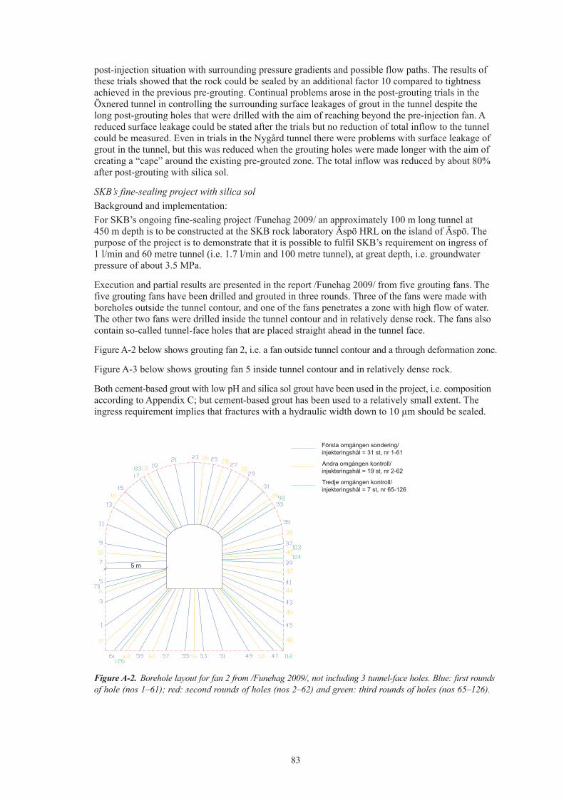
83
post-injection situation with surrounding pressure gradients and possible flow paths. The results of these trials showed that the rock could be sealed by an additional factor 10 compared to tightness achieved in the previous pre-grouting. Continual problems arose in the post-grouting trials in the Öxnered tunnel in controlling the surrounding surface leakages of grout in the tunnel despite the long post-grouting holes that were drilled with the aim of reaching beyond the pre-injection fan. A reduced surface leakage could be stated after the trials but no reduction of total inflow to the tunnel could be measured. Even in trials in the Nygård tunnel there were problems with surface leakage of grout in the tunnel, but this was reduced when the grouting holes were made longer with the aim of creating a “cape” around the existing pre-grouted zone. The total inflow was reduced by about 80% after post-grouting with silica sol.
SKB’s fine-sealing project with silica solBackground and implementation:For SKB’s ongoing fine-sealing project /Funehag 2009/ an approximately 100 m long tunnel at 450 m depth is to be constructed at the SKB rock laboratory Äspö HRL on the island of Äspö. The purpose of the project is to demonstrate that it is possible to fulfil SKB’s requirement on ingress of 1 l/min and 60 metre tunnel (i.e. 1.7 l/min and 100 metre tunnel), at great depth, i.e. groundwater pressure of about 3.5 MPa.
Execution and partial results are presented in the report /Funehag 2009/ from five grouting fans. The five grouting fans have been drilled and grouted in three rounds. Three of the fans were made with boreholes outside the tunnel contour, and one of the fans penetrates a zone with high flow of water. The other two fans were drilled inside the tunnel contour and in relatively dense rock. The fans also contain so-called tunnel-face holes that are placed straight ahead in the tunnel face.
Figure A-2 below shows grouting fan 2, i.e. a fan outside tunnel contour and a through deformation zone.
Figure A-3 below shows grouting fan 5 inside tunnel contour and in relatively dense rock.
Both cement-based grout with low pH and silica sol grout have been used in the project, i.e. composition according to Appendix C; but cement-based grout has been used to a relatively small extent. The ingress requirement implies that fractures with a hydraulic width down to 10 µm should be sealed.
Figure A-2. Borehole layout for fan 2 from /Funehag 2009/, not including 3 tunnel-face holes. Blue: first rounds of hole (nos 1–61); red: second rounds of holes (nos 2–62) and green: third rounds of holes (nos 65–126).
5 m
Första omgången sondering/injekteringshål = 31 st, nr 1-61
Andra omgången kontroll/injekteringshål = 19 st, nr 2-62
Tredje omgången kontroll/injekteringshål = 7 st, nr 65-126
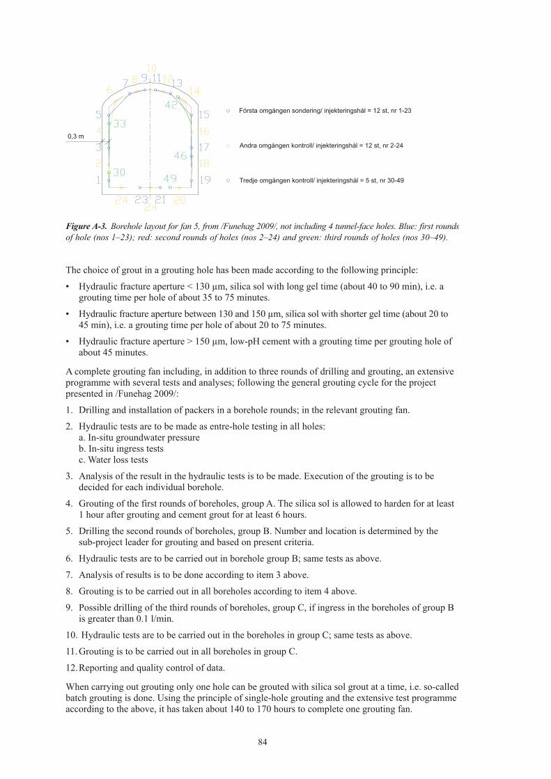
84
The choice of grout in a grouting hole has been made according to the following principle:
• Hydraulic fracture aperture < 130 µm, silica sol with long gel time (about 40 to 90 min), i.e. a grouting time per hole of about 35 to 75 minutes.
• Hydraulic fracture aperture between 130 and 150 µm, silica sol with shorter gel time (about 20 to 45 min), i.e. a grouting time per hole of about 20 to 75 minutes.
• Hydraulic fracture aperture > 150 µm, low-pH cement with a grouting time per grouting hole of about 45 minutes.
A complete grouting fan including, in addition to three rounds of drilling and grouting, an extensive programme with several tests and analyses; following the general grouting cycle for the project presented in /Funehag 2009/:
1. Drilling and installation of packers in a borehole rounds; in the relevant grouting fan.
2. Hydraulic tests are to be made as entre-hole testing in all holes:a. In-situ groundwater pressureb. In-situ ingress testsc. Water loss tests
3. Analysis of the result in the hydraulic tests is to be made. Execution of the grouting is to be decided for each individual borehole.
4. Grouting of the first rounds of boreholes, group A. The silica sol is allowed to harden for at least 1 hour after grouting and cement grout for at least 6 hours.
5. Drilling the second rounds of boreholes, group B. Number and location is determined by the sub-project leader for grouting and based on present criteria.
6. Hydraulic tests are to be carried out in borehole group B; same tests as above.
7. Analysis of results is to be done according to item 3 above.
8. Grouting is to be carried out in all boreholes according to item 4 above.
9. Possible drilling of the third rounds of boreholes, group C, if ingress in the boreholes of group B is greater than 0.1 l/min.
10. Hydraulic tests are to be carried out in the boreholes in group C; same tests as above.
11. Grouting is to be carried out in all boreholes in group C.
12. Reporting and quality control of data.
When carrying out grouting only one hole can be grouted with silica sol grout at a time, i.e. so-called batch grouting is done. Using the principle of single-hole grouting and the extensive test programme according to the above, it has taken about 140 to 170 hours to complete one grouting fan.
Figure A-3. Borehole layout for fan 5, from /Funehag 2009/, not including 4 tunnel-face holes. Blue: first rounds of hole (nos 1–23); red: second rounds of holes (nos 2–24) and green: third rounds of holes (nos 30–49).
0,3 m
Första omgången sondering/ injekteringshål = 12 st, nr 1-23
Andra omgången kontroll/ injekteringshål = 12 st, nr 2-24
Tredje omgången kontroll/ injekteringshål = 5 st, nr 30-49

85
Result:The result of the project is based partly on hydraulic tests of inspection holes in the fans, before, between and also after the grouting, and partly on tests in measuring weirs.
Table A-1 presents calculated median conductivity before and after grouting of fan 1, 2, 3, 4 and 5. The calculated conductivities are based on the results from inspection holes in the respective fan /Funehag 2009/.
That which can be noted in Table A-1 is that the applied grouting concept, i.e. grouting with silica sol and with complementation using a low-pH cement in larger hydraulic fractures, achieves about the same median conductivity after grouting regardless of whether a water-bearing zone or a relatively dense rock mass is grouted.
The report /Funehag 2009/ also presents measurements of the flows in the measuring weirs. The measured flows in the measuring weirs are below the maximum permitted flows, i.e. the requirement regarding inflow has been fulfilled.
Table A-1. Calculated median conductivities from presented results in /Funehag 2009/.
Grouting fan Median conductivity, before grouting (m/s)
Median conductivity, after grouting (m/s)
Notes
1 2⋅10–9 2⋅10–11 Rock with less water2 20⋅10–9 2⋅10–11 Water-bearing zone3 0.2⋅10–9 0.6⋅10–11 Rock with less water4 0.02⋅10–9 0.4⋅10–11 “Dense” rock5 0.02⋅10–9 0.2⋅10–11 “Dense” rock
ReferencesAhlbrecht T, 2005. Sinking the Konradsberg shaft using the Nonel detonator system. Gluckauf mining report 1-2005.
Butron C, Gustafson G, Funehag J, 2008. Grouting in the Nygård tunnel: Pre-grouting design for drop sealing and evaluation. Rapport 2008:2. Geologiska institutionen. Chalmers tekniska högskola, Göteborg.
Bäckblom G, Christiansson R, Lagerstedt L, 2004. Choice of rock excavation methods for the Swedish deep repository for spent nuclear fuel. SKB R-04-62, Svensk Kärnbränslehantering AB.
Carlsson A, Christiansson R, 2007. Construction experience compilation report (CECR) SKB R-07-10, Svensk Kärnbränslehantering AB.
Carlsson A, Lintu Y, Olsson T, 1987. Undersökningar av utförda injekteringsarbeten i slutförvar för reaktoravfall (SFR) Forsmark, U (B)1987/41, Vattenfall.
Chang Y, Swindell R, Bogdanoff I, Lindström B, Termen J, Starsec P, 2005. Study of tunnelling through water-beaing fracture zones – Baseline study on technical issues with NE-1 as reference. SKB R-05-25, Svensk Kärnbränslehantering AB.
Chunlai Y, Zongmin W, 2005. Surface pre-grouting and freezing for shaft sinking in aquifer formations. Mine water and the environment 24:209-212.
Claesson L-Å, Nilsson G, 2004. Forsmark site investigation – Drilling of the telescopic borehole KFM01A at drilling site DS1, P-rapport P-03-32, May 2004, Svensk Kärnbränslehantering AB.
Dalmalm T, Eriksson M, Janson T, Brantberger M, Slunga A, Dehlin P, Stille H, 2000. Injekteringsförsök vid Södra Länkens bergtunnlar. Rapport 3075, Avd för Jord- och Bergmekanik, KTH, Stockholm.
Dierz H K O, 1982. Aspect of advanced grouting during shaft in South Africa. Int J of Mine Water, vol 2 dec 1982.
86
Edrud P, Svensson H, 2007. Design och uppföljning av injektering I berg. En fältstudie av dropp-tätning i två större järnvägstunnlar. Examensarbete 2007:4, Väg- och vattenbyggnad, Chalmers.
Ellison T, 2007. Erfarenheter av injektering med silika sol, Törnskogstunneln. BK 2007. Bergsprängningskommittens 52:a möte. Stockholm.
Emmelin A, Eriksson M, Fransson Å, 2004. Characterisation, design and execution of two grouting fans at 450 m level, Äspö HRL. SKB R-04-58, Svensk Kärnbränslehantering AB
Funehag J, 2007. Grouting of Fractured Rock with Silica Sol. Grouting design based on penetration length. Geologiska institutionen, Chalmers tekniska högskola, Göteborg.
Funhag J, 2009. (in swedish) Injektering av TASS-tunneln – delresultat tom september 2008. R-08-123, Svensk Kärnbränslehantering AB.
Granberg N, Knutsson, 2008. Kvalitetssäkring av efterinjektering. En fältstudie i Nygårdstunneln. Examensarbete 2008:19. Geologiska institutionen, Chalmers tekniska högskola, Göteborg.
Heinz W F, 1988. Pre-cementation of deep shaft. Int J of Mine Water, vol 7 dec 1988.
Heinz W F, 1993. Ultra deep grout barriers. Grouting in rock and concrete. Balkema 1993.
Hermansson J, 1995. Structural geology of waterbearing fractures. PR 25-95-23, Svensk Kärnbränslehanterin AB.
Kipo E Ja, Polozov Ju A, Lagunov V A, Lushnikova O Ju, 1984. Experience in sealing water bearing strata during deep shaft sinking. Int J of Mine Water, vol 3 dec 1984.
Markström I, Erlström M, 1996. Äspö hard rock laboratory-overview of documentation of tunnel, niches and core boreholes, ProgressReport HRL-96-19, Svensk Kärnbränslehantering AB.
Rehbock-Sander M, Meier R, 2000. Sedrun access and ventilation shaft for the new Siant Gotthard railway base tunnel. AITES-ITA 2000 – world tunnel congress – tunnel under pressure. Vol 24 pp 615–620.
Rhén I, Stanfors R, 1993. Passage through water-bearing fracture zones-Evaluation of investigations in fracture zones NE1, EW-7 and NE-3, ProgressReport 25-92-18, Svensk Kärnbränslehantering AB
Stille H, Gustafson G, Håkansson U, Olsson P, 1993. Passage of water-bearing fracture zones – Experiences from the grouting of the section 1–1,400 m of the tunnel, ProgressReport 25-92-19, Svensk Kärnbränslehantering AB.
Stille H, Janson T, Olsson, P. (1994): Passage of water-bearing fracture zones – Experiences from the grouting of the section 1,340–2,565 m of the tunnel, Progress Report 25-94-13, Svensk Kärnbränslehantering AB.
Vägverket, 1993. Grundvatten, tätning och infiltration – bergtekniska anvisningar för projektering av ringen och yttre tvärleden. ANV004. Vägverket, Stockholm.

87
Appendix B
Input data for calculating inflow of water Tables B1–B4 presents the input data that has been used concerning hydraulic characteristics, K or T, depth below surface level (water pressure), H, and also radius, rt or rs, for different functional areas, underground openings and parts of the rock mass.
Table B1. Input data for calculating the inflow, i.e. ground behaviour, to functional area “accesses”.
Underground opening/part of rock mass/depth H (m) T (m2/s) or K (m/s) r (rt, rs) (m)
Ramp (depth 0–470 m)FFM02 (0–50 m) 25 Kmax = 2⋅10–5
Ktyp = 1⋅10–6
Kmin = 2⋅10–8
rt:3.0
FFM02 (50–100 m) 75 Kmax = 2⋅10–5
Ktyp = 1⋅10–6
Kmin = 2⋅10–8
rt:3.0
FFM01 (100–200 m) 150 Ktyp = 1⋅10–7 rt:3.0FFM01 (200–400 m) 300 Ktyp = 5⋅10–10 rt:3.0FFM01 (400–470 m) 435 Ktyp = 6⋅10–11 rt:3.0Steeply dipping zones (200–400 m) 300 Tmax = 1⋅10–6
Ttyp = 1⋅10–8
Tmin = 1⋅10–10
rt:3.0
Steeply dipping zones (400–470 m) 435 Tmax = 1⋅10–6
Ttyp = 1⋅10–8
Tmin = 1⋅10–10
rt:3.0
Shaft (from central area to surface level)FFM02 (0–50 m) 25 Tmax = 1⋅10–3
Ttyp = 5⋅10–5
Tmin = 1⋅10–6
rs:2.0
FFM02 (50–100 m) 75 Tmax = 1⋅10–3
Ttyp = 5⋅10–5
Tmin = 1⋅10–6
rs:2.0
FFM01 (100–200 m) 150 Ttyp = 1⋅10–5 rs:2.0FFM01 (200–400 m) 300 Ttyp = 1⋅10–7 rs:2.0FFM01 (400–470 m) 435 Ttyp = 4⋅10–9 rs:2.0Steeply dipping zones (200–400 m) 300 Tmax = 1⋅10–6
Ttyp = 1⋅10–8
Tmin = 1⋅10–10
rs:2.0
Table B2. Input data for calculating the inflow, i.e. ground behaviour, to functional area “central area”.
Underground opening/part of rock mass/depth H (m) T (m2/s) or K (m/s) r (rt, rs) (m)
Rock caverns (6) (depth 470 m)FFM01 470 Ktyp = 6⋅10–11 rt:8.0Steeply dipping zones 470 Tmax = 1⋅10–6
Ttyp = 1⋅10–8
Tmin = 1⋅10–10
rt:8.0
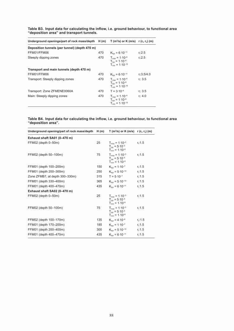
88
Table B3. Input data for calculating the inflow, i.e. ground behaviour, to functional area “deposition area” and transport tunnels.
Underground openings/part of rock mass/depth H (m) T (m2/s) or K (m/s) r (rt, rs) (m)
Deposition tunnels (per tunnel) (depth 470 m)FFM01/FFM06 470 Ktyp = 6⋅10–11 rt:2.5Steeply dipping zones 470 Tmax = 1⋅10–6
Ttyp = 1⋅10–8
Tmin = 1⋅10–10
rt:2.5
Transport and main tunnels (depth 470 m)FFM01/FFM06 470 Ktyp = 6⋅10–11 rt:3.5/4.0Transport: Steeply dipping zones 470 Tmax = 1⋅10–6
Ttyp = 1⋅10–8
Tmin = 1⋅10–10
rt: 3.5
Transport: Zone ZFMENE0060A 470 T = 3⋅10–8 rt: 3.5Main: Steeply dipping zones 470 Tmax = 1⋅10–6
Ttyp = 1⋅10–8
Tmin = 1⋅10–10
rt: 4.0
Table B4. Input data for calculating the inflow, i.e. ground behaviour, to functional area “deposition area”.
Underground opening/part of rock mass/depth H (m) T (m2/s) or K (m/s) r (rt, rs) (m)
Exhaust shaft SA01 (0–470 m)FFM02 (depth 0–50m) 25 Tmax = 1⋅10–3
Ttyp = 5⋅10–5
Tmin = 1⋅10–6
rt:1.5
FFM02 (depth 50–100m) 75 Tmax = 1⋅10–3
Ttyp = 5⋅10–5
Tmin = 1⋅10–6
rt:1.5
FFM01 (depth 100–200m) 150 Ktyp = 1⋅10–7 rt:1.5FFM01 (depth 200–300m) 250 Ktyp = 5⋅10–10 rt:1.5Zone ZFMB7, at depth 300–330m) 315 T = 5⋅10–7 rt:1.5FFM01 (depth 330–400m) 365 Ktyp = 5⋅10–10 rt:1.5FFM01 (depth 400–470m) 435 Ktyp = 6⋅10–11 rt:1.5Exhaust shaft SA02 (0–470 m)FFM02 (depth 0–50m) 25 Tmax = 1⋅10–3
Ttyp = 5⋅10–5
Tmin = 1⋅10–6
rt:1.5
FFM02 (depth 50–100m) 75 Tmax = 1⋅10–3
Ttyp = 5⋅10–5
Tmin = 1⋅10–6
rt:1.5
FFM02 (depth 100–170m) 135 Ktyp = 4⋅10–8 rs:1.5FFM01 (depth 170–200m) 185 Ktyp = 1⋅10–7 rt:1.5FFM01 (depth 200–400m) 300 Ktyp = 5⋅10–10 rt:1.5FFM01 (depth 400–470m) 435 Ktyp = 6⋅10–11 rt:1.5

89
Appendix C
Grout recipesMemoGrout for final depository, design D2This memo is provided by SKB, and presents the grout recipes that are supplied for final repository design D2.
The products, compositions and properties that are presented here are the same as those used, or that have resulted from, the fine sealing project at Äspö (SU32516). This means that SKB has its own experience of the presented compositions at 450 m depth – although to a relatively small extent – except for the plug grout which was not used in the project.
Formal handling of grout choiceAccording to the nuclear fuel project the choice of grout needs to be motivated and formulated in a technical decision; this will subsequently be done by SKB.
Silica solThe name of the silica sol product is Meyco MP320 and it has a dry content of 40%. The fluid is named sol because it is a colloidal solution, i.e. fine particles of silica suspended in water (not sedimentary).
Meyco MP320 has a density of 1.3 at 20 degrees C.
A salt, sodium chloride or calcium chloride, is added to control the gelling. It has also been demonstrated in the field that it is easier to mix the silica sol with sodium chloride than with calcium chloride.
The sodium chloride solution contains 10 per cent by weight sodium chloride and has a density of 1.0 at 20 degrees C.
The mixing ratio controls the gelling time, which is one of the variables in the design. Normal mixing ratios can be 4–6 parts silica sol to 1 part sodium chloride solution, but this may also vary further depending on how one wish to choose borehole spacing and grouting pressure.
Examples of gelling times:
Weight ratio: silica sol/ NaCl solution 4.5:1 5:1 5.5:1Gelling time at 15ºC [min] 21 35 59
Cement-based groutThe cement-based grout has been developed in cooperation by Posiva and SKB and subsequently further developed by Posiva. Due to national product differences the proportion of active substance in the super plasticiser is somewhat smaller in the fine sealing project at Äspö than in the super plasticiser of the original composition.
In addition to the injection grout, Posiva also tested a plug grout for filling tight holes.
In the fine sealing project at Äspö, SKB mainly has used the originally composed grout, but also a thicker grout (lower water/dry material ratio) referred to below as Stop-grout from the fine sealing project.

90
Composition, Injection grout
Weight ratio Material in the fine sealing project
Water 1.68Portland cement* 1.00 Ultrafin 16Silica fume** 1.37 Grout AidSuper plasticiser*** 0.07 SIKA MelcreteWater/dry material (W/DM) 1.4
* Sulphate resistant Ordinary Portland cement with d95 on 16µm, type Ultrafin 16 or equivalent.** Dispersed silica fume, microsilica with d90 = 1 µm type GroutAid or equivalent. The density is to be between 1,350–1,410 kg/m3 and 50%±2% of the solution is to consist of solid particles.*** Super plasticiser, naphthalene-sulphonate based, density about 1,200 kg/m3, type Melcrete.
Properties, Injection grout:The following properties have been measured in the field when testing injection grout in the fine sealing project:
Mean value
Density [kg/m3] 1,330Marsh-cone time [s] 43Shear limit [Pa] 15Viscosity [mPas] 22Shear strength 6h [kPa] 1.5Separation 2 h [%] 0
The following properties of injection grout have been measured in Posiva laboratory tests:
bmin [µm] 40bcrit [µm] 88
Composition, Plug grout
Weight ratio Comments
Water 0.80Portland cement 1.00 Ultrafin 16Silica fume 1.38 Grout AidSuper plasticiser 0.07 SIKA MelcreteWater/dry material (W/DM) 0.9
Properties, Plug groutMeasured properties from the laboratory of Posiva’s plug grout direct after mixing; values from Posiva:
Property Mean value
Density [kg/m3] 1,490Marsh-cone time [s] > 100Shear limit [Pa] 114Viscosity [mPas] 90Shear strength 6h [kPa] 1.3

91
Composition, Stop grout from the fine sealing project:
Weight ratio Comments
Water 0.64Portland cement 1.00 Injecting 30Silica fume 1.37 Grout AidSuper plasticiser 0.07 SIKA MelcreteWater/dry material (W/DM) 0.82
Composition, Stop grout from the fine sealing project:Measured properties from the field of stop grout in the fine sealing project:
Property Mean value
Density [kg/m3] 1,520Marsh-cone time [s] 52Shear limit [Pa] 15Viscosity [mPas] 30

Ark
itekt
kopi
a A
B, B
rom
ma,
201
9
Underground D
esign Forsmark, Layout D
2 – Grouting
R-08-114