underground service index jun 20 section 3
TRANSCRIPT
UNDERGROUND SERVICE INDEX
JUN 20
SECTION 3
GENERAL Residential Service Routing Guide .................................................................. 3-1-8 to 3-1-11 Secondary Service Entrance Details .............................................................................. 3-2-11 Multiple Service Cabinets (Tap Boxes) ......................................................... 3-2-12 to 3-2-14 Overhead to Underground Conversion ....................................................... 3-2-15 and 3-2-16 D1.9 Electric Vehicle Rate ............................................................................................ 3-2-17 Customer Installation Guidelines ....................................................................... 3-3-1 to 3-3-9 METER ENCLOSURES 1 Ф CL 200 Meter Installation ......................................................................................... 3-4-1 1 Ф CL 200, 2 Position Horizontal Meter Installation .................................................. 3-4-3.1 1 Ф CL 320 Meter Installation ...................................................................................... 3-4-3.2 Line Conductor Termination............................................................................................ 3-4-4 CABLE POLES & SERVICE MOUNTS OH Fed UG Service to Pedestal (Truck Accessible Locations) ...................................... 3-4-5 OH Fed UG Service to Pedestal (Non-Truck Accessible Locations) ........................... 3-4-5.1 Post Mounted Services ..................................................................................................... 3-4-6 Pedestal Mounted Services 200 Amp ........................................................................... 3-4-6.1 OH Fed UG Services (Truck Accessible Locations) ......................................... 3-4-7 to 3-4-9 OH Fed UG Services (Non-Truck Accessible Locations) ........................... 3-4-7.1 to 3-4-9.1 Conductor Identification ................................................................................................ 3-4-11 Temporary Service Pedestals ...................................................................... 3-5-11 and 3-5-12 Secondary Installation Procedures ................................................................. 3-5-15 to 3-5-18 PADMOUNT FOUNDATIONS Transformer Pad Specifications ......................................................................... 3-6-1 to 3-6-4 Grounding Specifications................................................................................................. 3-6-9 Support Posts ................................................................................................................. 3-6-10 Box Pad Guidelines........................................................................................ 3-6-12 to 3-6-14 Equipment Clearances ................................................................................... 3-7-11 to 3-7-12 SIM-ESIG SIM-ESIG: INDEX-1.S3
Note: Click on the content title or page number(s) to jump to the first page of that subject.
UNDERGROUND SERVICE INDEX
AUG 20
SECTION 3 (Cont.) SERVICE EQUIPMENT
Preconstruction Meter Mount ..................................................................... 3-12-1 to 3-12-4 CATV Power Supplies............................................................................................. 3-13-11 Mobile Home Service ............................................................................. 3-14-17 to 3-14-22 Pedestal Mounted Service Over 200 Amps............................................................... 3-14-25 Telephone Company Power Pedestal........................................................... 3-15-1 to 3-15-4 Cellular Tower Services ............................................................................3-15-5 and 3-15-6 High Rise Transformers ............................................................................3-15-7 and 3-15-8 SIM-ESIG SIM-ESIG: INDEX-2.S3
UNDERGROUND SERVICE 3-1-8 FEB 16
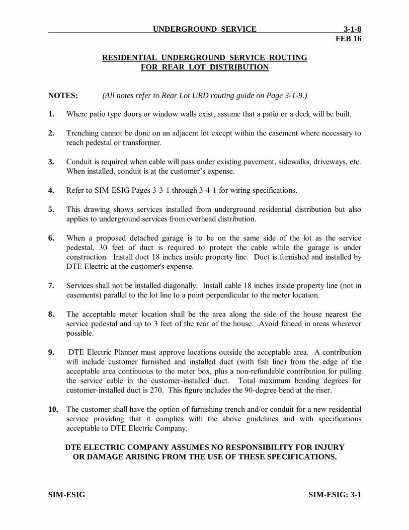
RESIDENTIAL UNDERGROUND SERVICE ROUTING FOR REAR LOT DISTRIBUTION NOTES: (All notes refer to Rear Lot URD routing guide on Page 3-1-9.) 1. Where patio type doors or window walls exist, assume that a patio or a deck will be built. 2. Trenching cannot be done on an adjacent lot except within the easement where necessary to
reach pedestal or transformer. 3. Conduit is required when cable will pass under existing pavement, sidewalks, driveways, etc.
When installed, conduit is at the customer’s expense. 4. Refer to SIM-ESIG Pages 3-3-1 through 3-4-1 for wiring specifications. 5. This drawing shows services installed from underground residential distribution but also
applies to underground services from overhead distribution. 6. When a proposed detached garage is to be on the same side of the lot as the service
pedestal, 30 feet of duct is required to protect the cable while the garage is under construction. Install duct 18 inches inside property line. Duct is furnished and installed by DTE Electric at the customer's expense.
7. Services shall not be installed diagonally. Install cable 18 inches inside property line (not in
easements) parallel to the lot line to a point perpendicular to the meter location. 8. The acceptable meter location shall be the area along the side of the house nearest the
service pedestal and up to 3 feet of the rear of the house. Avoid fenced in areas wherever possible.
9. DTE Electric Planner must approve locations outside the acceptable area. A contribution
will include customer furnished and installed duct (with fish line) from the edge of the acceptable area continuous to the meter box, plus a non-refundable contribution for pulling the service cable in the customer-installed duct. Total maximum bending degrees for customer-installed duct is 270. This figure includes the 90-degree bend at the riser.
10. The customer shall have the option of furnishing trench and/or conduit for a new residential
service providing that it complies with the above guidelines and with specifications acceptable to DTE Electric Company.
DTE ELECTRIC COMPANY ASSUMES NO RESPONSIBILITY FOR INJURY OR DAMAGE ARISING FROM THE USE OF THESE SPECIFICATIONS. SIM-ESIG SIM-ESIG: 3-1

SIM-ESIG
3-1-9UNDERGROUND SERVICE
REAR LOT U.R.D.
RESIDENTIAL UNDERGROUND SERVICE ROUTING GUIDE
DESIGN PRACTICES
HO
US
E
PEDESTAL
LO
T
LI
NE
3’
MA
X
3’ MAX
PEDESTAL
DRIVEWAY
ODC
OD
C
18’’
18’’
3’ MAX
LOT LI
NE
FIELD
DRAIN
LOCATION SEE NOTE 8
ACCEPTABLE METER
LINE
EASEMENT
SE
E
NO
TE 6
NO
DU
CT
RE
QUI
RE
D
SEE NOTE 9
DUCT
INSTALLED
CUSTOMER
GARAGE
EXISTINGBOUNDARY
EASEMENT
ODC
SEE NOTE 7
SEE NOTE 2
PEDESTAL
STREET
18’’
ODC
SEE NOTE 1
8’ MAX
PA
TI
O
PE
DE
ST
AL
SE
E
NO
TE 6
PR
OP
ER
TY
LI
NE
SE
E
NO
TE 3
SE
E
NO
TE 3
GA
RA
GE
PR
OP
OS
ED
HO
US
E
HO
USE
HOUSE
HOUSE
SEE PAGE 3-1-8 FOR NOTES
3’ MAX
FEB 16
DTE ELECTRIC COMPANY
UNDERGROUND SERVICE 3-1-10
OCT 17
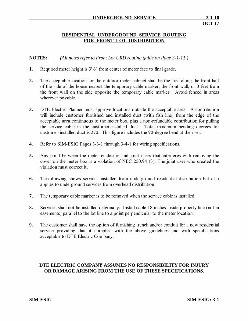
RESIDENTIAL UNDERGROUND SERVICE ROUTING FOR FRONT LOT DISTRIBUTION NOTES: (All notes refer to Front Lot URD routing guide on Page 3-1-11.) 1. Required meter height is 3' 6" from center of meter face to final grade. 2. The acceptable location for the outdoor meter cabinet shall be the area along the front half
of the side of the house nearest the temporary cable marker, the front wall, or 3 feet from the front wall on the side opposite the temporary cable marker. Avoid fenced in areas wherever possible.
3. DTE Electric Planner must approve locations outside the acceptable area. A contribution
will include customer furnished and installed duct (with fish line) from the edge of the acceptable area continuous to the meter box, plus a non-refundable contribution for pulling the service cable in the customer-installed duct. Total maximum bending degrees for customer-installed duct is 270. This figure includes the 90-degree bend at the riser.
4. Refer to SIM-ESIG Pages 3-3-1 through 3-4-1 for wiring specifications.
5. Any bond between the meter enclosure and joint users that interferes with removing the cover on the meter box is a violation of NEC 250.94 (3). The joint user who created the violation must correct it.
6. This drawing shows services installed from underground residential distribution but also
applies to underground services from overhead distribution. 7. The temporary cable marker is to be removed when the service cable is installed. 8. Services shall not be installed diagonally. Install cable 18 inches inside property line (not in
easements) parallel to the lot line to a point perpendicular to the meter location. 9. The customer shall have the option of furnishing trench and/or conduit for a new residential
service providing that it complies with the above guidelines and with specifications acceptable to DTE Electric Company.
DTE ELECTRIC COMPANY ASSUMES NO RESPONSIBILITY FOR INJURY OR DAMAGE ARISING FROM THE USE OF THESE SPECIFICATIONS. SIM-ESIG SIM-ESIG: 3-1

SIM-ESIG
UNDERGROUND SERVICE
FRONT LOT U.R.D.
RESIDENTIAL UNDERGROUND SERVICE ROUTING GUIDE
DESIGN PRACTICES
SEE NOTE 6
MARKER
TEMPORARY CABLE
GA
RA
GE
PR
OP
OS
ED
3’
3’
18’’
18’’
LOT LI
NE
HALF WAY
LO
T
LI
NE
PR
OP
ER
TY
LI
NE
TRENCH
MAIN
LOCATION SEE NOTE 2
ACCEPTABLE METER
LINE
EASEMENT
MA
RK
ER
TE
MP
OR
AR
Y
CA
BL
E
WAY
HALF
SE
E
NO
TE 8
STREET
HO
USE
HO
US
E
HO
USE
HOUSE
HOUSE
SEE NOTE 3
INSTALLED DUCT
CUSTOMER
SEE NOTE 7
3-1-11FEB 16
SEE PAGE 3-1-10 FOR NOTES
DTE ELECTRIC COMPANY
SE
E
NO
TE
1
&
5
SIM-ESIG
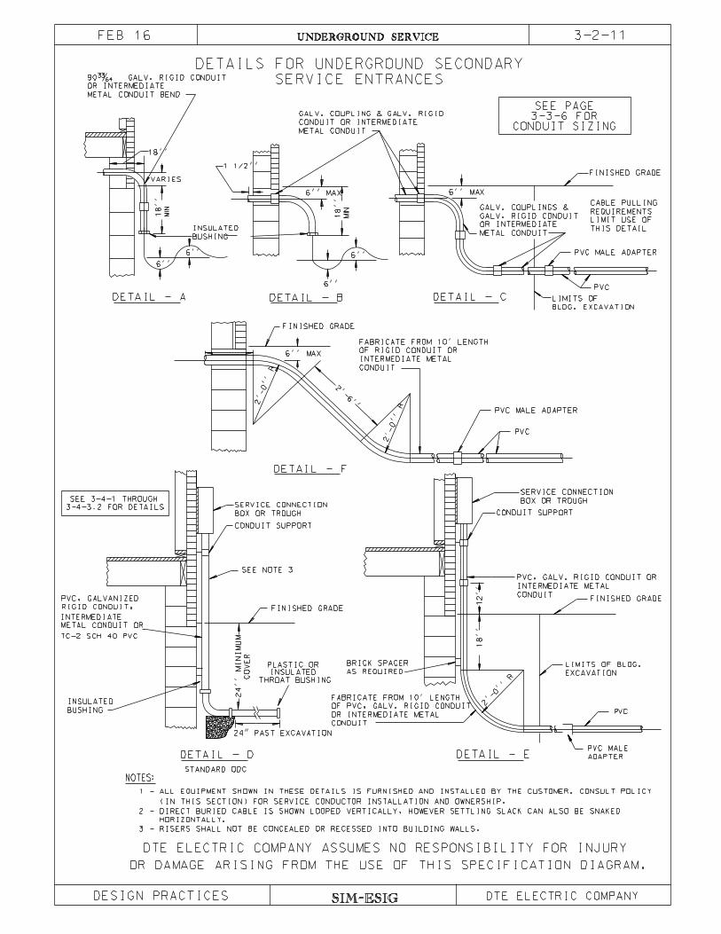
3-2-11UNDERGROUND SERVICE
DESIGN PRACTICES
OR DAMAGE ARISING FROM THE USE OF THIS SPECIFICATION DIAGRAM.
CONDUIT SIZING
SEE PAGE3-3-6 FOR
METAL CONDUIT
OR INTERMEDIATE
GALV. RIGID CONDUIT
GALV. COUPLINGS &
DETAIL - F
FABRICATE FROM 10’ LENGTH
OF RIGID CONDUIT OR
INTERMEDIATE METAL
CONDUIT
PVC, GALV. RIGID CONDUIT OR
FABRICATE FROM 10’ LENGTH
OF PVC, GALV. RIGID CONDUIT
OR INTERMEDIATE METAL
CONDUIT
BUSHING
INSULATED
PVC, GALVANIZED
DETAIL - B DETAIL - CBLDG. EXCAVATION
LIMITS OF
PVC
PVC MALE ADAPTER
THIS DETAIL
LIMIT USE OF
REQUIREMENTS
CABLE PULLING
6’’ MAX
FINISHED GRADE1 1/2’’
METAL CONDUIT
CONDUIT OR INTERMEDIATE
GALV. COUPLING & GALV. RIGID
6’’
6’’
MIN
18’’
6’’ MAX
PVC
PVC MALE ADAPTER
2’-0’’
R
2’-0’’
R
2’-6’’
6’’ MAX
FINISHED GRADE
2 - DIRECT BURIED CABLE IS SHOWN LOOPED VERTICALLY, HOWEVER SETTLING SLACK CAN ALSO BE SNAKED
HORIZONTALLY.
1 - ALL EQUIPMENT SHOWN IN THESE DETAILS IS FURNISHED AND INSTALLED BY THE CUSTOMER. CONSULT POLICY
(IN THIS SECTION) FOR SERVICE CONDUCTOR INSTALLATION AND OWNERSHIP.
LIMITS OF BLDG.
EXCAVATION
BRICK SPACER
AS REQUIRED
SERVICE CONNECTION
BOX OR TROUGHSERVICE CONNECTION
BOX OR TROUGH
FINISHED GRADE
CONDUIT SUPPORT
CONDUIT SUPPORT
FINISHED GRADE
18’’
12’’
2’-0’’ R
DETAIL - D
NOTES:
DETAIL - E
DETAIL - A
INSULATED
BUSHING
VARIES
18’’18’’
MIN
6’’
6’’
90� GALV. RIGID CO
OR INTERMEDIATE
METAL CONDUIT BEND
PVC MALE
ADAPTER
PVC
INTERMEDIATE METAL
CONDUIT
INTERMEDIATE
3 - RISERS SHALL NOT BE CONCEALED OR RECESSED INTO BUILDING WALLS.
SEE NOTE 3
DETAILS FOR UNDERGROUND SECONDARY
SERVICE ENTRANCES
METAL CONDUIT OR
RIGID CONDUIT,
TC-2 SCH 40 PVC
STANDARD ODC
24’’
MI
NI
MU
M
CO
VE
R
PLASTIC OR
THROAT BUSHING
INSULATED
24" PAST EXCAVATION
SEE 3-4-1 THROUGH
3-4-3.2 FOR DETAILS
FEB 16
DTE ELECTRIC COMPANY ASSUMES NO RESPONSIBILITY FOR INJURY
DTE ELECTRIC COMPANY

SIM-ESIG
UNDERGROUND SERVICE
SINGLE OR 3 PHASE
SERVICE TAP BOX
DESIGN PRACTICES
OR DAMAGE ARISING FROM THE USE OF THIS SPECIFICATION DIAGRAM.
CONSTRUCTION STANDARDS.
CABINET WILL BE MADE OF 14 GAUGE STEEL PER NEMA 3R
APPROVED SEALABLE LATCH.
ONLY ONE SERVICE ALLOWED PER LUG.
ALL BUS BARS WILL BE FLAT TO FRONT.
CUSTOMER TO PROVIDE EQUIPMENT BONDING JUMPER PER NEC ARTICLE 250.
INVERT CABLE CONNECTIONS FOR SERVICE CONNECTION AT TOP.
CABINET WILL BE FURNISHED AND INSTALLED BY CUSTOMER.
FRONT VIEW SIDE VIEW
10 LUGS MAXIMUM
HASP
SEALING
ACCEPTABLE
1/2’’ X 2 1/2’’ LONG STUD
NOTES:
2" MIN.
4’’
BACK OF ENCLOSURE
MOUNTING HOLES IN
10’’MIN.
30’’
GROUNDING LUG
1.
2.
3.
4.
5.
6.
7.
36"
FOR EQUIPMENT
BONDING JUMPER
MIN.
4’’
MIN.
4’’
MIN.
4’’
MIN.
3-2-12FEB 16
DTE ELECTRIC COMPANY ASSUMES NO RESPONSIBILITY FOR INJURY
DTE ELECTRIC COMPANY
THE DOOR OF THE TAP BOX MUST BE EQUIPPED WITH A DTE
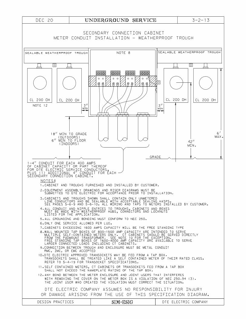
PLUS (1) ADDITIONAL 4" CONDUIT FOR EACH
1-4" CONDUIT FOR EACH 400 AMPS
OF CABINET CAPACITY OR PART THEREOF
FOR DTE ELECTRIC SERVICE CONDUCTORS,
SECONDARY CONNECTION CABINET.
(INDOORS)
6" MIN TO FLOOR
(OUTDOORS)
18" MIN TO GRADE
GRADE
42"
MIN.
MAX.
6'
DTE ELECTRIC COMPANY ASSUMES NO RESPONSIBILITY FOR INJURY
OR DAMAGE ARISING FROM THE USE OF THIS SPECIFICATION DIAGRAM.
SECONDARY CONNECTION CABINET
3"
NOTE 8
CL 200 OHCL 200 OH
METER CONDUIT INSTALLATION - WEATHERPROOF TROUGH
CL 200 OHCL 200 OH
MIN MIN
3"
SEALABLE WEATHERPROOF TROUGH SEALABLE WEATHERPROOF TROUGH
3-2-13UNDERGROUND SERVICEDEC 20
DESIGN PRACTICES DTE ELECTRIC COMPANYSIM-ESIG
NOTES:
CABINETS AND TROUGHS SHOWN SHALL CONTAIN ONLY UNMETERED
LINE CONDUCTORS AND BE SEALABLE WITH ACCEPTABLE SEALING HASPS.
SEE PAGES 5-6-9 AND 5-6-10. ALL WIRING AND TAPS TO METERS INSTALLED BY CUSTOMER.
EQUIPMENT ASSEMBLY DRAWINGS AND RISER DIAGRAMS MUST BE
ALL CONDUIT AND NIPPLE ENTRIES TO TROUGHS, CABINETS AND BOXES
LISTED FOR THE APPLICATION.
MUST BE MADE WITH WEATHERPROOF HUBS, CONNECTORS AND LOCKNUTS
ALL GROUNDING AND BONDING MUST CONFORM TO NEC 250.
ONLY ONE SERVICE ALLOWED PER LUG.
3.
4.
5.
6.
7.
8.
1.
2.
9.
RMC, IMC, OR EMC ACCEPTED
MULTIPLE SELF-CONTAINED METERS ONLY. CT CABINETS SHOULD BE SERVED DIRECTLY
FROM THE PADMOUNT TRANSFORMER. SEE NOTE 10 FOR THE EXCEPTION.
LARGER CONNECTED LOADS INCLUDING CT CABINETS.
FREE STANDING TAP BOXES OF 1600-4000 AMP CAPACITY ARE AVAILABLE TO SERVE
TRANSOCKETS SHALL BE TREATED LIKE A SELF CONTAINED METER OF THEIR RATED CLASS.
WALL MOUNTED TAP BOXES OF 800-1600 AMP CAPACITY ARE INTENDED TO SERVE
CABINETS EXCEEDING 1600 AMPS CAPACITY WILL BE THE FREE STANDING TYPE
CONNECTION BETWEEN TROUGH AND ENCLOSURE MUST BE METAL CONDUIT
CABINET AND TROUGHS FURNISHED AND INSTALLED BY CUSTOMER.
REFER TO 5-4-19 FOR TRANSOCKET SPECIFICATIONS.
SUBMITTED TO DTE ELECTRIC FOR ACCEPTANCE PRIOR TO INSTALLATION.
DTE ELECTRIC APPROVED TRANSOCKETS MAY BE FED FROM A TAP BOX.10.
11.SELF CONTAINED METERS, CT CABINETS OR TRANSOCKETS FED FROM A TAP BOX
SHALL NOT EXCEED THE NAMEPLATE RATING OF THE TAP BOX.
12.
THE JOINT USER WHO CREATED THE VIOLATION MUST CORRECT THE SITUATION.
WITH REMOVING THE COVER ON THE METER BOX IS A VIOLATION OF NEC 250.94 (3).
ANY BOND BETWEEN THE METER ENCLOSURE AND JOINT USERS THAT INTERFERES
NOTE 12

MIN.
3" 3"
MIN.
DESIGN PRACTICES DTE ELECTRIC COMPANY
METER CONDUIT INSTALLATION
SECONDARY CONNECTION CABINET
OR DAMAGE ARISING FROM THE USE OF THIS SPECIFICATION DIAGRAM.
OF CABINET CAPACITY OR PART THEREOF
(INDOORS)
6" MIN TO FLOOR
(OUTDOORS)
CUSTOMER
GRADE
MIN.
42"
MAX.
6'
1-4" CONDUIT FOR EACH 400 AMPS
PLUS (1) ADDITIONAL 4" CONDUIT FOR EACHSECONDARY CONNECTION CABINET.
18" MIN TO GRADE
3-2-14
NOTE 8NOTE 9
CL 200 OHCL 200 OH CL 200 UG
SERVICE
CONDUITS
CONDUIT
POTENTIAL SERVICE
FOR DTE ELECTRIC SERVICE CONDUCTORS,
DTE ELECTRIC COMPANY COMPANY ASSUMES NO RESPONSIBILITY FOR INJURY
SIM-ESIG
UNDERGROUND SERVICEDEC 20
NOTE 12
NOTES:
CABINET AND CONDUIT FURNISHED AND INSTALLED BY CUSTOMER.
CABINETS AND TROUGHS SHOWN SHALL CONTAIN ONLY UNMETERED
LINE CONDUCTORS AND BE SEALABLE WITH ACCEPTABLE SEALING HASPS.
SEE PAGES 5-6-9 AND 5-6-10. ALL WIRING AND TAPS TO METERS INSTALLED BY CUSTOMER.
EQUIPMENT ASSEMBLY DRAWINGS AND RISER DIAGRAMS MUST BE
ALL CONDUIT AND NIPPLE ENTRIES TO TROUGHS, CABINETS AND BOXES
LISTED FOR THE APPLICATION.
MUST BE MADE WITH WEATHERPROOF HUBS, CONNECTORS AND LOCKNUTS
ALL GROUNDING AND BONDING MUST CONFORM TO NEC 250.
ONLY ONE SERVICE ALLOWED PER LUG.
3.
4.
5.
6.
7.
8.
1.
2.
9.CONNECTION FROM TAP BOX TO ENCLOSURE MUST BE METAL CONDUIT - RMC, IMC, OR
EMC ACCEPTED. CUSTOMER TO PROVIDE CONDUCTOR BETWEEN METER AND TAP BOX.
MULTIPLE SELF-CONTAINED METERS ONLY. CT CABINETS SHOULD BE SERVED DIRECTLY
FROM THE PADMOUNT TRANSFORMER. SEE NOTE 10 FOR THE EXCEPTION.
LARGER CONNECTED LOADS INCLUDING CT CABINETS.
FREE STANDING TAP BOXES OF 1600-4000 AMP CAPACITY ARE AVAILABLE TO SERVE
10.
TRANSOCKETS SHALL BE TREATED LIKE A SELF CONTAINED METER OF THEIR RATED CLASS.
WALL MOUNTED TAP BOXES OF 800-1600 AMP CAPACITY ARE INTENDED TO SERVE
11.
CABINETS EXCEEDING 1600 AMPS CAPACITY WILL BE THE FREE STANDING TYPE
REFER TO 5-4-19 FOR TRANSOCKET SPECIFICATIONS.
SELF CONTAINED METERS, CT CABINETS OR TRANSOCKETS FED FROM A TAP BOX
SUBMITTED TO DTE ELECTRIC FOR ACCEPTANCE PRIOR TO INSTALLATION.
DTE ELECTRIC APPROVED TRANSOCKETS MAY BE FED FROM A TAP BOX.
SHALL NOT EXCEED THE NAMEPLATE RATING OF THE TAP BOX.
12.
THE JOINT USER WHO CREATED THE VIOLATION MUST CORRECT THE SITUATION.
WITH REMOVING THE COVER ON THE METER BOX IS A VIOLATION OF NEC 250.94 (3).
ANY BOND BETWEEN THE METER ENCLOSURE AND JOINT USERS THAT INTERFERES
MAX.
9'

SIM-ESIG
3-2-15UNDERGROUND SERVICE
MAINTAINING CONTINUITY OF SERVICE
OR DAMAGE ARISING FROM THE USE OF THIS SPECIFICATION DIAGRAM.
1-9-69
CONTRACTOR METER CONVERSION
DESIGN PRACTICES
DTE ELECTRIC COMPANY ASSUMES NO RESPONSIBILITY FOR INJURY
DTE ELECTRIC COMPANY
DO NOT INSTALL JUMPER
DE-ENERGIZING.
CABLE FROM ODC AFTER
REQUIRED ON METAL CONDUIT,
NONMETALLIC BUSHING
WARNING
METER
EXISTING
BEEN INSTALLED AND REPLACE METER.
CUSTOMER CONTRACTOR -
SEE PAGE 3-4-1.
INSTALLED BY CONTRACTOR.
MAY BE U.G.
METER BOX ALSO
BLADES.
SEE PAGES 3-4-1 THROUGH 3-4-3.2
MUST HAVE APPROPRIATE SWEEP
DTE CREW - CUT OR REMOVE
CUSTOMER CONTRACTOR NOTES:
3. CONNECT THE SERVICE ENTRANCE CABLE INTO THE METER BOX ON THE LOAD SIDE.
4. INSTALL TEMPORARY CABLE FROM LOAD SIDE OF EXISTING METER ENCLOSURE TO LOAD
STEP 1 (PRIOR TO ANY DTE WORK):
STEP 5 (AFTER DTE UG SERVICE IS ENERGIZED):
7. REMOVE OLD METER ENCLOSURE AND OLD SERVICE RISER CABLE OR CONDUIT FROM BUILDING.
1. INSPECT CUSTOMER’S INSTALLATION FOR SPEC COMPLIANCE.
2. IF S-BASE METER IS EXISTING IN THE OH METER ENCLOSURE, REQUEST LINES
TO TRANSFER THIS METER TO THE NEW UG METER ENCLOSURE.
1. INSTALL UG CABLE. COIL UG CABLE AT BASE OF POLE AND INSIDE METER BOX.
2. TERMINATE UG CABLE ON THE SOURCE SIDE OF THE NEW UG METER ENCLOSURE.
3. IF A-BASE METER IS INVOLVED, RECALL AFTER UG SERVICE HAS
NOTE 5).
5. INSTALL KNOCKOUT FILLER PLUG IN METER ENCLOSURE (SEE CUSTOMER CONTRACTOR
4. REMOVE TEMPORARY CABLE FROM BETWEEN THE TWO METER ENCLOSURES.
TEMPORARY CABLE FED FROM LOAD SIDE OF
EXISTING METER TO LOAD SIDE OF NEW METER
5. LEAVE KNOCKOUT FILLER PLUG IN BOTTOM OF METER ENCLOSURE AND INSTALL PLASTIC COVER.
THROUGH BOTTOM KNOCKOUT HOLE
6. INSTALL METER INTO NEW UG METER ENCLOSURE.
STEP 2 - DTE SERVICE PLANNER NOTES:
STEP 4 - DTE LINE CREW NOTES:
(MAY BE ON RIGHT OR LEFT)DTE UG ENTRANCE CABLE
(MAY BE ON RIGHT OR LEFT)
2. INSTALL APPROVED DTE ELECTRIC ENCLOSURE FOR UNDERGROUND SERVICE.
1. USE 2" CONDUIT FOR 3/0 AND 3" CONDUIT FOR 350 KCMIL CABLE.
INSTALLED SERVICE
DTE ELECTRIC
6. DO NOT TAP TOP LUGS OF NEW METER ENCLOSURE.
SEE CUSTOMER CONTRACTOR NOTE 1
STEP 3 - DTE UG CONTRACTOR CREW NOTES:
TO EXISTING
METER ENCLOSURE
SOURCE (TOP)
LOAD (BOTTOM)
1. DE-ENERGIZE AND REMOVE OH SERVICE AND METER.
3. TRAIN UG SERVICE UP POLE AND TAP TO SECONDARY. USE RISER BRACKET.
SERVICE ENTRANCE CABLE
SEE CUST.
CONT. NOTE 6
CREATED THE VIOLATION MUST CORRECT THE SITUATION.
THE COVER ON THE METER BOX IS A VIOLATION OF NEC 250.94 (3). THE JOINT USER WHO
ANY BOND BETWEEN THE METER ENCLOSURE AND JOINT USERS THAT INTERFERES WITH REMOVING
FOR CONINUITY OF SERVICE, THE SAME TEMPORARY WIRING BETWEEN METERS SHALL APPLY FOR
AN UPGRADE FROM A CL200 TO CL320 SERVICE.
SIDE OF NEW METER ENCLOSURE (USE CENTER KNOCKOUT HOLE, IN BOTTOM OF ENCLOSURE).
NOV 18
SIM-ESIG
UNDERGROUND SERVICE 3-2-16NOV 18
DESIGN PRACTICES DTE ELECTRIC COMPANY
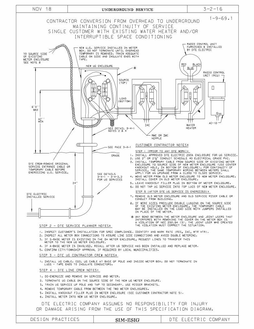
MAINTAINING CONTINUITY OF SERVICE
CONTRACTOR CONVERSION FROM OVERHEAD TO UNDERGROUND
OR DAMAGE ARISING FROM THE USE OF THIS SPECIFICATION DIAGRAM.
SINGLE CUSTOMER WITH EXISTING WATER HEATER AND/OR
INTERRUPTIBLE SPACE CONDITIONING
1-9-69.1
DTE ELECTRIC COMPANY ASSUMES NO RESPONSIBILITY FOR INJURY
NIPPLE
MAX
6’0’’
MIN
HEATER
WATERIACAC-10
INSTALLED SERVICE
GRADE
42’’
SEE PAGE 3-4-1
BLUE
BLACKRED
UNIT (RCU)
RADIO CONTROL
ENERGIZING U.G. SERVICE.
TEMPORARY CABLE BEFORE
SERVICE ENTRANCE CABLE OR
TAPE.
CABLE ON SIDE AND INSULATE ENDS WITH
TEMPORARY IS REMOVED. TRAIN ADEQUATE
BOX. DO NOT TERMINATE UNTIL OVERHEAD
NEW U.G. SERVICE INSTALLED IN METER FURNISHED & INSTALLED
RADIO CONTROL UNIT
NEW UG ENCLOSURE
FOR UG SERVICES
RMC OR IMC
DTE CREW-REMOVE ORIGINAL
BY DTE ELECTRIC
DTE ELECTRIC
3-4-1 - 3-4-3.2
SEE DETAILS
CUSTOMER CONTRACTOR NOTES:
STEP 1 (PRIOR TO ANY DTE WORK):
STEP 5 (AFTER DTE UG SERVICE IS ENERGIZED):
2. TERMINATE UG CABLE ON THE SOURCE SIDE OF THE NEW UG METER ENCLOSURE.
4. REMOVE TEMPORARY CABLE FROM BETWEEN THE TWO METER ENCLOSURES.
6. INSTALL METER INTO NEW UG METER ENCLOSURE.
STEP 2 - DTE SERVICE PLANNER NOTES:
STEP 4 - DTE LINE CREW NOTES:
METER TO THE NEW UG METER ENCLOSURE.
3. IF S-BASE METER IS EXISTING IN THE OH METER ENCLOSURE, REQUEST LINES TO TRANSFER THIS
4. IF A-BASE METER IS INVOLVED, RECALL AFTER UG SERVICE HAS BEEN INSTALLED AND REPLACE METER.
5. INSTALL KNOCKOUT FILLER PLUG IN METER ENCLOSURE (SEE CUSTOMER CONTRACTOR NOTE 5).
2. INSPECT ALL METER BOX CONNECTIONS TO ASSURE LINE SIDE CONNECTIONS AND AVOID DOUBLE METERING.
5. CONFIRM CITY/TOWNSHIP APPROVAL IF REQUIRED BY LOCAL MUNICIPALITIES.
LUGS - TAPE ENDS TO INSULATE CONDUCTORS.
1. INSTALL UG CABLE. COIL UG CABLE AT BASE OF POLE AND INSIDE METER BOX. DO NOT TERMINATE IN
NOTES 2 & 4
SEE DETAIL 3-4-1
STEP 3 - DTE UG CONTRACTOR CREW NOTES:
METER ENCLOSURE
(TOP)
SOURCE
(BOTTOM)
LOAD
1. INSPECT CUSTOMER’S INSTALLATION FOR SPEC COMPLIANCE. IDENTIFY AND MARK RATE (RES, IAC, WTR HTR).
24"
1. DE-ENERGIZE AND REMOVE OH SERVICE AND METER.
3. TRAIN UG SERVICE UP POLE AND TAP TO SECONDARY. USE RISSER BRACKETS.
TO SOURCE SIDE
OF EXISTING
IN PLACE OF THE METER.
MAY BE INSTALLED ON THE LOAD SIDE WITH JUMPERS INSTALLED
OF THE EXISTING METER ENCLOSURE, THE TEMPORARY CABLE
8. IF WIRE SIZES PRECLUDE DOUBLE LUGGING ON THE SOURCE SIDE
6. DO NOT TAP UG SERVICE INTO TOP LUGS OF NEW METER ENCLOSURE.
1. INSTALL APPROVED DTE ELECTRIC 200A ENCLOSURE FOR UG SERVICE.
INSTALL COVER IN OLD METER ENCLOSURE.
4. MOVE METER FROM OLD METER ENCLOSURE TO NEW METER ENCLOSURE.
5. LEAVE KNOCKOUT FILLER PLUG IN BOTTOM OF METER ENCLOSURE.
SEE NOTE 8
2. USE 2" OR 2�" CONDUIT SCHEDULE 40 ELECTRICAL GRADE PVC.
CONDUIT FROM BUILDING.
7. REMOVE OLD METER ENCLOSURE AND OLD SERVICE RISER CABLE OR
THE VIOLATION MUST CORRECT THE SITUATION.
A VIOLATION OF NEC 250.94 (3). THE JOINT USER WHO CREATED
INTERFERES WITH REMOVING THE COVER ON THE METER BOX IS
ANY BOND BETWEEN THE METER ENCLOSURE AND JOINT USERS THAT
APPLY FOR AN UPGRADE FROM A CL200 TO CL320 SERVICE.
SERVICE, THE SAME TEMPORARY WIRING BETWEEN METERS SHALL
KNOCKOUT HOLE, IN BOTTOM OF ENCLOSURE). FOR CONTINUITY OF
ENCLOSURE TO SOURCE SIDE OF NEW METER ENCLOSURE (USE CENTER
3. INSTALL TEMPORARY CABLE FROM SOURCE SIDE OF EXISTING METER
OR DAMAGE ARISING FROM THE USE OF THIS SPECIFICATION DIAGRAM.
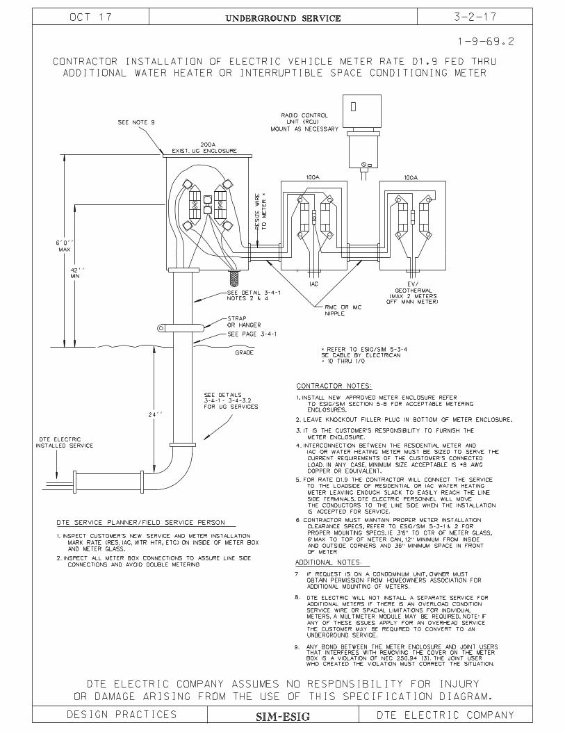
CONTRACTOR INSTALLATION OF ELECTRIC VEHICLE METER RATE D1.9 FED THRU
ADDITIONAL WATER HEATER OR INTERRUPTIBLE SPACE CONDITIONING METER
1-9-69.2
OCT 17 UNDERGROUND SERVICE 3-2-17
SIM-ESIGDESIGN PRACTICES
DTE ELECTRIC COMPANY ASSUMES NO RESPONSIBILITY FOR INJURY
DTE ELECTRIC COMPANY
AND METER GLASS.
1. INSPECT CUSTOMER’S NEW SERVICE AND METER INSTALLATION.
CONTRACTOR NOTES:
CONNECTIONS AND AVOID DOUBLE METERING.
NIPPLE
MAX
6’0’’
MIN
IAC
GRADE
42’’
24’’
OR HANGER
SEE PAGE 3-4-1
UNIT (RCU)
RADIO CONTROL
FOR UG SERVICES
EV/
GEOTHERMAL
(MAX 2 METERS
SE CABLE BY ELECTRICAN
* REFER TO ESIG/SIM 5-3-4
* 10 THRU 1/0
EXIST. UG ENCLOSURE
200A
100A 100A
RE
SIZ
E
WIR
E
TO
ME
TE
R *
TO ESIG/SIM SECTION 5-8 FOR ACCEPTABLE METERING
1. INSTALL NEW APPROVED METER ENCLOSURE REFER
METER ENCLOSURE.
ENCLOSURES.
IAC OR WATER HEATING METER MUST BE SIZED TO SERVE THE
CURRENT REQUIREMENTS OF THE CUSTOMER’S CONNECTED
LOAD. IN ANY CASE, MINIMUM SIZE ACCEPTABLE IS #8 AWG
COPPER OR EQUIVALENT.
TO THE LOADSIDE OF RESIDENTIAL OR IAC WATER HEATING
METER LEAVING ENOUGH SLACK TO EASILY REACH THE LINE
THE CONDUCTORS TO THE LINE SIDE WHEN THE INSTALLATION
IS ACCEPTED FOR SERVICE.
CLEARANCE SPECS, REFER TO ESIG/SIM 5-3-1 & 2 FOR
PROPER MOUNTING SPECS. IE 3’6" TO CTR OF METER GLASS,
6’ MAX TO TOP OF METER CAN, 12" MINIMUM FROM INSIDE
AND OUTSIDE CORNERS AND 36" MINIMUM SPACE IN FRONT
OF METER.
OBTAIN PERMISSION FROM HOMEOWNERS ASSOCIATION FOR
ADDITIONAL MOUNTING OF METERS.
ADDITIONAL METERS IF THERE IS AN OVERLOAD CONDITION
SERVICE WIRE OR SPACIAL LIMITATIONS FOR INDIVIDUAL
METERS, A MULTIMETER MODULE MAY BE REQUIRED. NOTE: IF
ANY OF THESE ISSUES APPLY FOR AN OVERHEAD SERVICE
THE CUSTOMER MAY BE REQUIRED TO CONVERT TO AN
UNDERGROUND SERVICE.
OFF MAIN METER)
MOUNT AS NECESSARY
MARK RATE (RES, IAC, WTR HTR, ETC) ON INSIDE OF METER BOX
RMC OR IMC
DTE SERVICE PLANNER/FIELD SERVICE PERSON
SIDE TERMINALS. DTE ELECTRIC PERSONNEL WILL MOVE
DTE ELECTRIC WILL NOT INSTALL A SEPARATE SERVICE FOR
2. INSPECT ALL METER BOX CONNECTIONS TO ASSURE LINE SIDE
2. LEAVE KNOCKOUT FILLER PLUG IN BOTTOM OF METER ENCLOSURE.
3. IT IS THE CUSTOMER’S RESPONSIBILITY TO FURNISH THE
4. INTERCONNECTION BETWEEN THE RESIDENTIAL METER AND
5. FOR RATE D1.9 THE CONTRACTOR WILL CONNECT THE SERVICE
6. CONTRACTOR MUST MAINTAIN PROPER METER INSTALLATION
INSTALLED SERVICE
DTE ELECTRIC
NOTES 2 & 4
SEE DETAIL 3-4-1
STRAP
3-4-1 - 3-4-3.2
SEE DETAILS
7.
8.
9.
SEE NOTE 9
IF REQUEST IS ON A CONDOMINUM UNIT, OWNER MUST
WHO CREATED THE VIOLATION MUST CORRECT THE SITUATION.
BOX IS A VIOLATION OF NEC 250.94 (3). THE JOINT USER
THAT INTERFERES WITH REMOVING THE COVER ON THE METER
ANY BOND BETWEEN THE METER ENCLOSURE AND JOINT USERS
ADDITIONAL NOTES:

UNDERGROUND SERVICE 3-3-1
APR 17
CUSTOMER CONTRACTOR UNDERGROUND SERVICE INSTALLATION
1. General. (a) Prior to the construction of any job, the customer or his authorized representative
must consult with the DTE Electric Planner at the appropriate Regional Center to determine acceptable construction standards. Failure to do so could result in added expenses, unnecessary delays, or both.
(b) This specification covers the installation by the customer’s electrical contractor of: (1) Customer furnished, owned, and maintained commercial service conductors. (2) Conduit for DTE Electric furnished, installed, owned, and maintained primary or
secondary commercial service conductors. (c) A DTE Electric Planner will inspect each installation. All material and workmanship
must be acceptable to DTE Electric. (d) DTE Electric will install conduit in public thoroughfare. 2. Rules and Regulations. When this specification conflicts with local rules, permission from the inspection authority
having jurisdiction may be required. See Rate Book for Electric Service Rule C6 for DTE Electric policy.
3. Installation of Secondary Cable. (a) Only one conductor per leg or phase shall be used for loads of 400 amperes or less
when conduit is required in public thoroughfares. (b) Not more than two conductors per phase shall be paralleled for loads of 400 to 800
amperes when conduit is required in public thoroughfares. (c) For delta connection, the power leg and neutral may be reduced in size as allowed by
the National Electrical Code. For wye connection, a full size neutral is advisable to allow for changes in building use such as large single phase loads or discharge lighting; however, the National Electrical Code does allow reduction of the neutral on a wye
service. [See NEC 250-24(C).] (d) The conductors shall be of sufficient length to make connection to DTE Electric
equipment. (See SIM-ESIG 3-5-15.) (e) Maximum number of conductors per conduit is eight, except in network areas. SIM-ESIG SIM-ESIG: 3-3

UNDERGROUND SERVICE 3-3-2
OCT 20 (f) Maximum number of secondary conductors per phase terminating in a padmount
transformer will be as follows:
(1) Three-phase (750 kVA and above) ............................................8
(2) Three-phase (500 kVA and below) ............................................6 For 8 cables maximum use terminal extension
SAP No. 100015563. (See UG Lines Construction Standards 1-9-211.)
(3) Single-phase ...............................................................................4 Note: Up to 3/0 AWG--8 cables maximum using
setscrew connector SAP No. 100067028 or terminal extension SAP No. 100015563. (See UG Lines Construction Standards 1-9-213 & 1-9-214.) (g) Maximum conductor size shall be 750 kcmil aluminum or copper. (h) Maximum number of conduits per cable pole is three. (i) On a cable pole, when paralleling of conductors is permissible, not more than three
conductors per phase may be paralleled. A maximum of six conductors may be installed in one conduit. DTE Electric personnel will connect conductors to Company equipment.
(j) Each conduit shall contain at least one conductor of each phase and one neutral. (Do
not install a separate grounding conductor in addition to the neutral.)
(k) DTE offers a multiple secondary termination cabinet allowing more than 8 sets of conductor terminations. Customer supplies secondary wires to and from cabinet.
4. Secondary Cable Termination. (a) Cabinets and Enclosures. Do not use current transformer cabinet or meter enclosure
line terminals to connect leads to other CT cabinets or meter enclosures. Use troughs or tap boxes except for the tandem meter assembly shown on page 5-3-6 or for separate space conditioning and water heating rates shown in Section 7. In unusual cases, the DTE Electric Planner may grant an exception.
(b) Troughs and Tap Boxes.
(1) Troughs. Tap connector assemblies with insulated supports or removable insulated covers are required to connect service cables from underground service conductors to meter boxes. These devices may be attached securely to the enclosure or have preformed insulated boots. Individual tap connectors other than split bolts are acceptable. Power distribution blocks or multi-tap connection blocks with insulated boots are preferred.
SIM-ESIG SIM-ESIG: 3-3
UNDERGROUND SERVICE 3-3-3
OCT 20
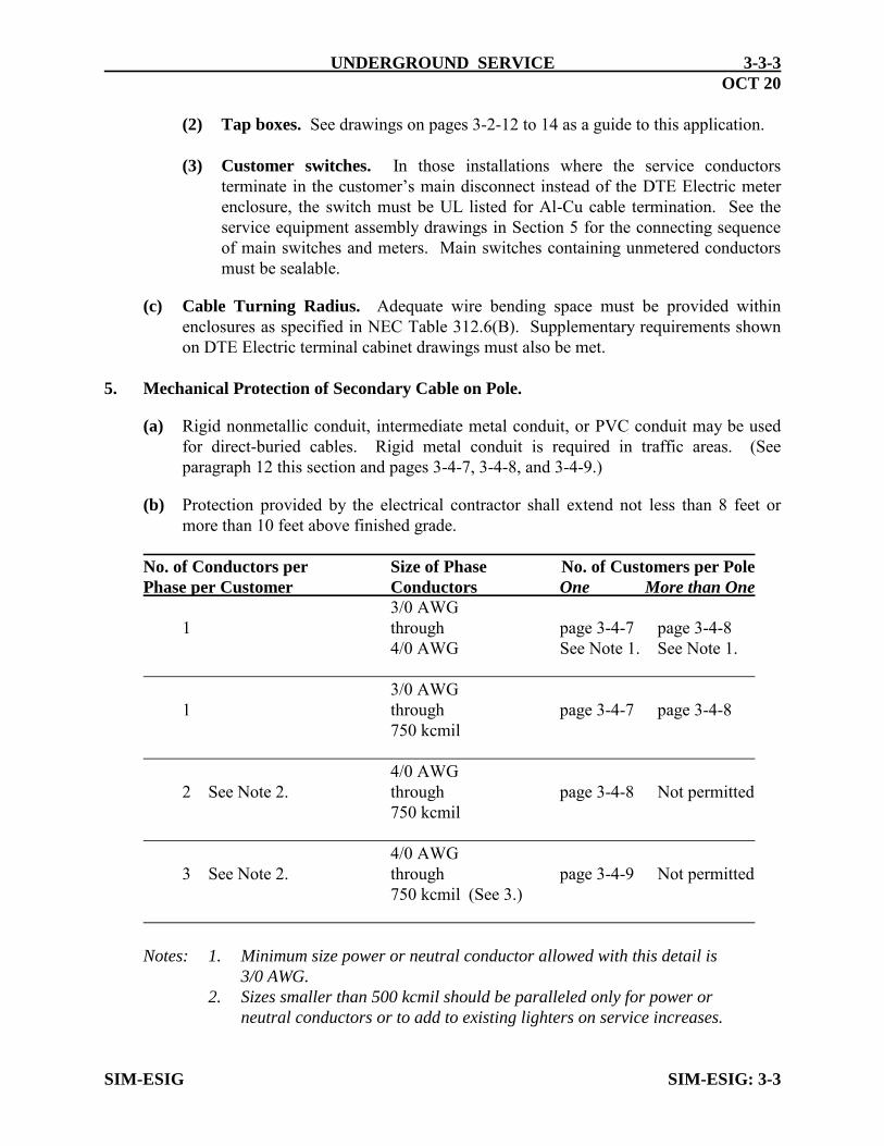
(2) Tap boxes. See drawings on pages 3-2-12 to 14 as a guide to this application. (3) Customer switches. In those installations where the service conductors
terminate in the customer’s main disconnect instead of the DTE Electric meter enclosure, the switch must be UL listed for Al-Cu cable termination. See the service equipment assembly drawings in Section 5 for the connecting sequence of main switches and meters. Main switches containing unmetered conductors must be sealable.
(c) Cable Turning Radius. Adequate wire bending space must be provided within
enclosures as specified in NEC Table 312.6(B). Supplementary requirements shown on DTE Electric terminal cabinet drawings must also be met.
5. Mechanical Protection of Secondary Cable on Pole. (a) Rigid nonmetallic conduit, intermediate metal conduit, or PVC conduit may be used
for direct-buried cables. Rigid metal conduit is required in traffic areas. (See paragraph 12 this section and pages 3-4-7, 3-4-8, and 3-4-9.)
(b) Protection provided by the electrical contractor shall extend not less than 8 feet or
more than 10 feet above finished grade.
No. of Conductors per Size of Phase No. of Customers per Pole
Phase per Customer Conductors One More than One
3/0 AWG 1 through page 3-4-7 page 3-4-8 4/0 AWG See Note 1. See Note 1. 3/0 AWG 1 through page 3-4-7 page 3-4-8 750 kcmil 4/0 AWG 2 See Note 2. through page 3-4-8 Not permitted 750 kcmil 4/0 AWG 3 See Note 2. through page 3-4-9 Not permitted 750 kcmil (See 3.) Notes: 1. Minimum size power or neutral conductor allowed with this detail is
3/0 AWG.
2. Sizes smaller than 500 kcmil should be paralleled only for power or
neutral conductors or to add to existing lighters on service increases. SIM-ESIG SIM-ESIG: 3-3

UNDERGROUND SERVICE 3-3-4
JAN 20
6. Secondary Conductors. (a) General. Stranded aluminum or copper conductors that meet Insulated Cable
Engineers Association (ICEA) standards shown below are acceptable. Cables shall be single conductor with nonmetallic sheath. All conductors, including neutral, shall be insulated with heat and moisture resistant material. Conductors shall be marked in compliance with NEC 310-11, particularly as to insulation type.
(b) ICEA Specifications. Rubber ........................................................................... S-19-081 Thermoplastic ............................................................... S-61-402 Cross-Linked Polyethylene ........................................... S-66-524 Ethylene Propylene Rubber .......................................... S-68-516 (c) Conductors in Conduit. (1) Fed from secondary cable pole.
a. Acceptable:
RHH, RHW, RHW-2--rubber (EPR) or polyethylene (XLP) XHHW, XHHW-2--cross-linked polyethylene
b. Not Acceptable:
TW, THW, THWN, or THHN--thermoplastic (2) Fed from transformer or pedestal.
a. Recommended:
RHH, RHW, RHW-2--rubber (EPR) or polyethylene (XLP) XHHW, XHHW-2--cross-linked polyethylene
b. Acceptable:
TW, THW, THWN, or THHN--thermoplastic (3) Fed from network.
Customer shall contact the Service Planner to arrange for the purchase and delivery of AC network service cable.
(d) Direct Buried Conductors.
a. Acceptable:
RHH, RHW, RHW-2--cross-linked polyethylene (XLP) USE, USE-2--underground service entrance
SIM-ESIG SIM-ESIG: 3-3
UNDERGROUND SERVICE 3-3-5FEB 16
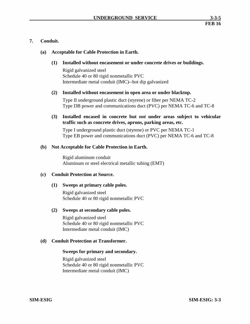
7. Conduit.
(a) Acceptable for Cable Protection in Earth.
(1) Installed without encasement or under concrete drives or buildings.
Rigid galvanized steelSchedule 40 or 80 rigid nonmetallic PVCIntermediate metal conduit (IMC)--hot dip galvanized
(2) Installed without encasement in open area or under blacktop.
Type II underground plastic duct (styrene) or fiber per NEMA TC-2Type DB power and communications duct (PVC) per NEMA TC-6 and TC-8
(3) Installed encased in concrete but not under areas subject to vehiculartraffic such as concrete drives, aprons, parking areas, etc.
Type I underground plastic duct (styrene) or PVC per NEMA TC-1Type EB power and communications duct (PVC) per NEMA TC-6 and TC-8
(b) Not Acceptable for Cable Protection in Earth.
Rigid aluminum conduitAluminum or steel electrical metallic tubing (EMT)
(c) Conduit Protection at Source.
(1) Sweeps at primary cable poles.
Rigid galvanized steelSchedule 40 or 80 rigid nonmetallic PVC
(2) Sweeps at secondary cable poles.
Rigid galvanized steelSchedule 40 or 80 rigid nonmetallic PVCIntermediate metal conduit (IMC)
(d) Conduit Protection at Transformer.
Sweeps for primary and secondary.
Rigid galvanized steelSchedule 40 or 80 rigid nonmetallic PVCIntermediate metal conduit (IMC)
SIM-ESIG SIM-ESIG: 3-3
UNDERGROUND SERVICE 3-3-6
JUL 16
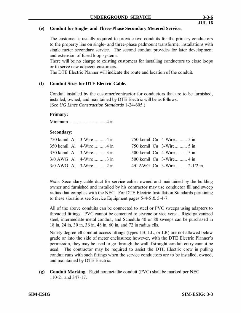
(e) Conduit for Single- and Three-Phase Secondary Metered Service. The customer is usually required to provide two conduits for the primary conductors
to the property line on single- and three-phase padmount transformer installations with single meter secondary service. The second conduit provides for later development and extension of fused loop systems.
There will be no charge to existing customers for installing conductors to close loops or to serve new adjacent customers.
The DTE Electric Planner will indicate the route and location of the conduit. (f) Conduit Sizes for DTE Electric Cable. Conduit installed by the customer/contractor for conductors that are to be furnished,
installed, owned, and maintained by DTE Electric will be as follows: (See UG Lines Construction Standards 1-24-605.)
Primary:
Minimum .............................. 4 in Secondary:
750 kcmil Al 3-Wire .......... 4 in 750 kcmil Cu 4-Wire .......... 5 in
350 kcmil Al 4-Wire .......... 4 in 750 kcmil Cu 3-Wire .......... 5 in
350 kcmil Al 3-Wire .......... 3 in 500 kcmil Cu 4-Wire .......... 5 in
3/0 AWG Al 4-Wire .......... 3 in 500 kcmil Cu 3-Wire .......... 4 in
3/0 AWG Al 3-Wire .......... 2 in 4/0 AWG Cu 3-Wire .......... 2-1/2 in
Note: Secondary cable duct for service cables owned and maintained by the building owner and furnished and installed by his contractor may use conductor fill and sweep radius that complies with the NEC. For DTE Electric Installation Standards pertaining to these situations see Service Equipment pages 5-4-5 & 5-4-7.
All of the above conduits can be connected to steel or PVC sweeps using adapters to
threaded fittings. PVC cannot be cemented to styrene or vice versa. Rigid galvanized steel, intermediate metal conduit, and Schedule 40 or 80 sweeps can be purchased in 18 in, 24 in, 30 in, 36 in, 48 in, 60 in, and 72 in radius ells.
Ninety degree ell conduit access fittings (types LB, LL, or LR) are not allowed below grade or into the side of meter enclosures; however, with the DTE Electric Planner’s permission, they may be used to go through the wall if straight conduit entry cannot be used. The contractor may be required to assist the DTE Electric crew in pulling conduit runs with such fittings when the service conductors are to be installed, owned, and maintained by DTE Electric.
(g) Conduit Marking. Rigid nonmetallic conduit (PVC) shall be marked per NEC 110-21 and 347-17. SIM-ESIG SIM-ESIG: 3-3

UNDERGROUND SERVICE 3-3-7FEB 16
(h) Service and Commercial Feeder Installation.
(1) Trench. The bottom of the trench should be level without sudden changes thatwould leave the conduit unsupported during backfill. Backfilling over plasticconduit should be done from the center towards both ends. Trenches forsecondary service conductors will be deep enough to assure 24 inches of coverfrom the top surface of the cable or conduit to finished grade. Trenches forprimary conductors will be deep enough to assure 30 inches of cover to grade.
(2) Plugs and fish line. Conduit must be plugged at both ends immediately afterinstallation to prevent entrance of foreign matter or water. The plugs used mustbe substantial enough to remain in place. If the conductors are to be furnishedand installed by DTE Electric, a stout cord such as nylon fish line will be left inthe conduit for the DTE Electric crew to pull in their pulling line.
(3) Conduit under buildings. Conduit and conductors shall not be run under onebuilding to serve another.
(4) Conduit length. When two-90 degree bends are used to turn conduit up at thebuilding and at the source, the length of the conduit should not exceed 200 feetfor secondary and 1000 feet for primary.
(5) Conduit bends. Bends in addition to those at the building and the sourceshould be avoided. If conditions make bends necessary, the overall length ofsecondary conduit should be reduced by 5 feet for each 10-degree increment ofdeflection beyond the two-90 degree bends at the ends. Primary conduit shouldbe reduced by 25 feet for each 10-degree increment of deflection beyond thetwo-90 degree bends. Total secondary or primary conduit curvature shall notexceed 270 degrees. Horizontal bends will have a minimum 10-foot radius (usetwo-45 degree ells with conduit spacer).
(6) Manholes. A manhole shall be installed when the overall conduit lengthapproaches or exceeds the limits in (4) and (5) above.
(7) Public thoroughfare. The Company will install the duct when an undergroundservice source is located in a public thoroughfare.
(8) Service termination point. Conduit installed by the contractor for DTEElectric furnished service conductors will terminate at an acceptable multipleservice cabinet either on the outside wall of the building or immediately inside.From there, the customer’s conductors will continue through or under thebuilding to the service entrance equipment.
SIM-ESIG SIM-ESIG 3-3

3-3-8 UNDERGROUND SERVICE 3-3-8
OCT 17
(9) Secondary service pedestal. When the supply is from an underground distribution pedestal in an easement, the use of an all conduit installation is not advisable since conduit cannot be properly terminated at a pedestal.
(10) Entrance below grade. If the service is designed to enter the building more than 6 inches
below grade, careful consideration must be given to the possibility that water may enter the building through or around the conduit. The customer will be responsible for correcting such a condition. (See page 3-2-11.)
(11) Swimming Pools. Underground wiring shall never be permitted under swimming pools. A minimum distance of 5 ft. shall exist between any underground supply
conductor(s) and the inside wall of the pool in compliance with NEC Article 680.10 and NESC 351(C)(1). Where space limitations prevent wiring from being routed a distance of 5 ft or more from the pool, such wiring shall be permitted where installed in rigid metal conduit, intermediate metal conduit, or a nonmetallic sch 40 pvc.
8. Grounding.
Note: Any bond between the meter enclosure and joint users that interferes with removing the cover on the meter box is a violation of NEC 250.94 (3). The joint user who created the violation must correct the situation.
(a) Primary Conduit. Primary metallic conduit will be grounded at the transformer with a bonding
jumper connected between the conduit bushing and the transformer grounding connection. The conduit grounding bushing and the bonding jumper will be furnished and installed by the contractor.
(b) Metallic Sweeps. Rigid steel or IMC sweeps protecting direct buried conductors, on the end of
plastic duct, or on non-continuous conduit will be grounded as above. (c) Secondary Conduit. Secondary rigid or intermediate metal conduit that runs continuously to the
building will not be grounded at the transformer since it will be grounded at the building per NEC requirements and this would cause a multiple ground path. Current taking an undesirable route on one of these multiple ground paths could cause problems such as conduit heating or tripping of the equipment ground-fault protection (GFPE).
(d) Transformers. Transformer pad ground rod installation and connection are shown on pages 3-6-9
and 3-6-12. 9. Padmount Foundations. (a) Specifications. Drawings of concrete padmount foundations for DTE Electric transformers are
shown on pages 3-6-1 to 3-6-4. (b) Clearances. Transformers must be located with proper clearances as shown on pages 3-7-11 and
3-7-12. The DTE Electric Planner must be consulted regarding pad location before construction begins.
(c) Guard Posts. If the transformer is subject to vehicular traffic, the contractor must install guard
posts as shown on page 3-6-10. The DTE Electric Planner must be consulted for the location of these posts.
SIM-ESIG SIM-ESIG: 3-3
UNDERGROUND SERVICE 3-3-9FEB 16
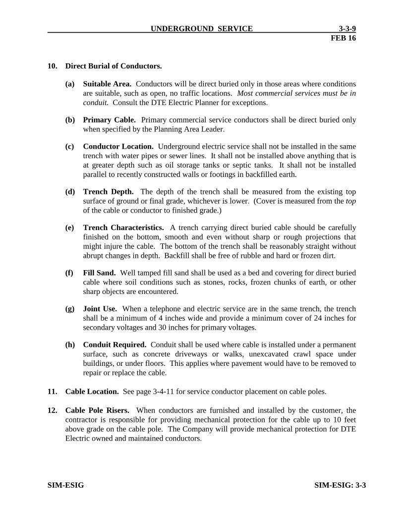
10. Direct Burial of Conductors.
(a) Suitable Area. Conductors will be direct buried only in those areas where conditionsare suitable, such as open, no traffic locations. Most commercial services must be inconduit. Consult the DTE Electric Planner for exceptions.
(b) Primary Cable. Primary commercial service conductors shall be direct buried onlywhen specified by the Planning Area Leader.
(c) Conductor Location. Underground electric service shall not be installed in the sametrench with water pipes or sewer lines. It shall not be installed above anything that isat greater depth such as oil storage tanks or septic tanks. It shall not be installedparallel to recently constructed walls or footings in backfilled earth.
(d) Trench Depth. The depth of the trench shall be measured from the existing topsurface of ground or final grade, whichever is lower. (Cover is measured from the topof the cable or conductor to finished grade.)
(e) Trench Characteristics. A trench carrying direct buried cable should be carefullyfinished on the bottom, smooth and even without sharp or rough projections thatmight injure the cable. The bottom of the trench shall be reasonably straight withoutabrupt changes in depth. Backfill shall be free of rubble and hard or frozen dirt.
(f) Fill Sand. Well tamped fill sand shall be used as a bed and covering for direct buriedcable where soil conditions such as stones, rocks, frozen chunks of earth, or othersharp objects are encountered.
(g) Joint Use. When a telephone and electric service are in the same trench, the trenchshall be a minimum of 4 inches wide and provide a minimum cover of 24 inches forsecondary voltages and 30 inches for primary voltages.
(h) Conduit Required. Conduit shall be used where cable is installed under a permanentsurface, such as concrete driveways or walks, unexcavated crawl space underbuildings, or under floors. This applies where pavement would have to be removed torepair or replace the cable.
11. Cable Location. See page 3-4-11 for service conductor placement on cable poles.
12. Cable Pole Risers. When conductors are furnished and installed by the customer, thecontractor is responsible for providing mechanical protection for the cable up to 10 feetabove grade on the cable pole. The Company will provide mechanical protection for DTEElectric owned and maintained conductors.
SIM-ESIG SIM-ESIG: 3-3

3-4-1
OR DAMAGE ARISING FROM THE USE OF THIS SPECIFICATION DIAGRAM.
SECONDARY UNDERGROUND SERVICE1-9-227
Single Phase CL 200 UG
DESIGN PRACTICES
DTE ELECTRIC COMPANY ASSUMES NO RESPONSIBILITY FOR INJURY
DTE ELECTRIC COMPANYSIM-ESIG
UNDERGROUND SERVICEFEB 21
+-
MAXIMUM
FINAL GRADE
24" MINIMUM
COVER
TO SOURCE
CABLEUNDERGROUND DUCT
PROPERTY LINETOP OF GROUND
SEE NOTES 1 & 4
SEE NOTES 1 & 2
METER ENCLOSURE
3'6"
MINIMUM
PROPER LINE
CONDUCTOR TERMINATION
LOADLINE
LOADLINE
6'0"
NOTE 8
TO ODC RISER CONDUIT
PLUG WITH DUX
SEAL OR EQUIVALENT
CONDUIT SIZE
CONDUIT CHART
2" 120"
FURNISHED AND
INSTALLED BY
CONTRACTOR.
CONTINUOUS CONDUIT - DISTURBED OR UNCOMPACTED SOIL
SEE NOTE 9
36"9 1/2"
CONDUIT LENGTH <15' CONDUIT LENGTH >15'
BY DTE
VERT. RADIUS VERT. RADIUS HORIZ. RADIUS
7
NOTE
SOIL
UNCOMPACTED
LOOSE
EXCAVATION
24" BEYOND
EXTEND SWEEP
SEE NOTE 4
BUSHING
NON-METALLIC ON PVC
GLUED JOINTS
SEE NOTE 1
OR STRAP
BRACKET, PIPE HANGER
SECURELY SUPPORTED
AT UNDERGROUND DUCT
PROTECTION OF DIRECT BURIAL CABLE
BELOW FOR VERT. RADIUS
SEE CONDUIT CHART
1. FURNISHED AND INSTALLED BY CONTRACTOR.
2. USE 2" CONDUIT FOR 3/0
RIGID GALVANIZED STEEL CONDUIT
INTERMEDIATE METAL CONDUIT (IMC)
NEMA TC-2 SCHEDULE 40 PVC
3. RISERS SHALL NOT BE CONCEALED OR RECESSED INTO BUILDING WALLS.
4. USE PLASTIC BUSHING OR INSULATED THROAT BUSHING. BOND PER N.E.C. ARTICLE 250.
PVC CONDUIT WITH REAMED AND ROUNDED EDGES DOES NOT REQUIRE BOTTOM BUSHING.
5. SEE OTHER PAGES IN THIS SECTION FOR CABLE AND TRENCH SPECIFICATIONS.
6. OWNER MUST PROVIDE A ROUTE CLEAR OF TREES, LARGE STUMPS AND OBSTRUCTIONS
WIDE ENOUGH TO ALLOW TRENCHING EQUIPMENT TO OPERATE.
7. SERVICE CABLES MUST BE TRAINED WITH AS MUCH SLACK AS POSSIBLE WITHIN THE BOX.
8. ANY FILL BENEATH THE CABLE TRENCH MUST BE AS SETTLED AND COMPACTED AS POSSIBLE.
THE BACKFILL MUST BE FREE OF RUBBLE AND CLODS OF HARD OR FROZEN DIRT.
9. THE CONDUIT MUST INCLUDE A SWEEP THAT EXTENDS 24" BEYOND UNDISTURBED SOIL.
THE BUILDER/ELECTRICIAN MUST MARK THE "BLIND SIDE" OF THE SWEEP.
10. GRADE MUST BE 4" OF THE FINAL FINISHED GRADE
11. ANY BOND BETWEEN THE METER ENCLOSURE AND JOINT USERS THAT INTERFERES WITH
REMOVING THE COVER ON THE METER BOX IS A VIOLATION OF NEC 250.94 (3).
THE JOINT USER WHO CREATED THE VIOLATION MUST CORRECT THE SITUATION.
NOTES:
SEE NOTE 11
LEFT OR RIGHT KNOCKOUT HOLE ENTRANCE CABLE MAY BE FED THROUGH SERVICE ENTRANCE CABLE AND DTE UG
SIM-ESIG
UNDERGROUND SERVICE
SECONDARY UNDERGROUND SERVICE
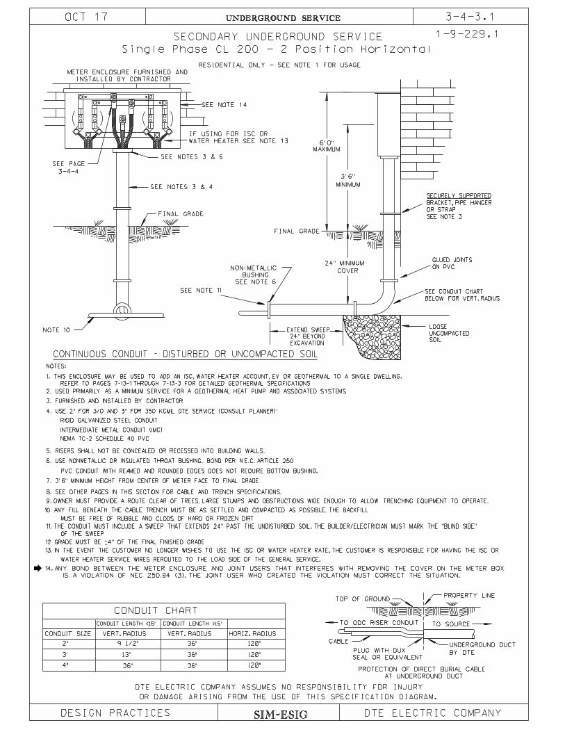
3-4-3.1
1-9-229.1
Single Phase CL 200 - 2 Position Horizontal
DESIGN PRACTICES DTE ELECTRIC COMPANY
3-4-4
SEE PAGE
3. FURNISHED AND INSTALLED BY CONTRACTOR.
5. RISERS SHALL NOT BE CONCEALED OR RECESSED INTO BUILDING WALLS.
INTERMEDIATE METAL CONDUIT (IMC)
RIGID GALVANIZED STEEL CONDUIT
NOTES:
8. SEE OTHER PAGES IN THIS SECTION FOR CABLE AND TRENCH SPECIFICATIONS.
6. USE NONMETALLIC OR INSULATED THROAT BUSHING. BOND PER N.E.C. ARTICLE 250.
SEE NOTES 3 & 4
SEE NOTES 3 & 6
FINAL GRADE
10. ANY FILL BENEATH THE CABLE TRENCH MUST BE AS SETTLED AND COMPACTED AS POSSIBLE. THE BACKFILL
NOTE 10
PVC CONDUIT WITH REAMED AND ROUNDED EDGES DOES NOT REQUIRE BOTTOM BUSHING.
11. THE CONDUIT MUST INCLUDE A SWEEP THAT EXTENDS 24" PAST THE UNDISTURBED SOIL. THE BUILDER/ELECTRICIAN MUST MARK THE "BLIND SIDE"
OF THE SWEEP
9. OWNER MUST PROVIDE A ROUTE CLEAR OF TREES, LARGE STUMPS AND OBSTRUCTIONS WIDE ENOUGH TO ALLOW TRENCHING EQUIPMENT TO OPERATE.
METER ENCLOSURE FURNISHED AND
INSTALLED BY CONTRACTOR
24" MINIMUM
COVER
SEE NOTE 11
CONTINUOUS CONDUIT - DISTURBED OR UNCOMPACTED SOIL
TO SOURCE
CABLEUNDERGROUND DUCT
PROPERTY LINETOP OF GROUND
TO ODC RISER CONDUIT
PLUG WITH DUX
SEAL OR EQUIVALENT
NEMA TC-2 SCHEDULE 40 PVC
MUST BE FREE OF RUBBLE AND CLODS OF HARD OR FROZEN DIRT.
2. USED PRIMARILY AS A MINIMUM SERVICE FOR A GEOTHERMAL HEAT PUMP AND ASSOCIATED SYSTEMS
7. 3’ 6" MINIMUM HEIGHT FROM CENTER OF METER FACE TO FINAL GRADE
12. GRADE MUST BE 4" OF THE FINAL FINISHED GRADE+-
6’ 0"
MAXIMUM
3’ 6"
MINIMUM
FINAL GRADE
RESIDENTIAL ONLY - SEE NOTE 1 FOR USAGE
WATER HEATER SEE NOTE 13
WATER HEATER SERVICE WIRES REROUTED TO THE LOAD SIDE OF THE GENERAL SERVICE.
CONDUIT SIZE
CONDUIT CHART
2"
3"
4"
120"
120"
120"
13"
36" 36"
36"
36"
9 1/2"
CONDUIT LENGTH <15’ CONDUIT LENGTH >15’
BY DTE
VERT. RADIUSVERT. RADIUS HORIZ. RADIUS
13. IN THE EVENT THE CUSTOMER NO LONGER WISHES TO USE THE ISC OR WATER HEATER RATE, THE CUSTOMER IS RESPONSIBLE FOR HAVING THE ISC OR
IF USING FOR ISC OR
4. USE 2" FOR 3/0 AND 3" FOR 350 KCMIL DTE SERVICE (CONSULT PLANNER):
OR DAMAGE ARISING FROM THE USE OF THIS SPECIFICATION DIAGRAM.
DTE ELECTRIC COMPANY ASSUMES NO RESPONSIBILITY FOR INJURY
14.
OCT 17
SEE NOTE 14
SOIL
UNCOMPACTED
LOOSE
EXCAVATION
24" BEYOND
EXTEND SWEEP
SEE NOTE 6
BUSHING
NON-METALLIC ON PVC
GLUED JOINTS
SEE NOTE 3
OR STRAP
BRACKET, PIPE HANGER
SECURELY SUPPORTED
AT UNDERGROUND DUCT
PROTECTION OF DIRECT BURIAL CABLE
BELOW FOR VERT. RADIUS
SEE CONDUIT CHART
REFER TO PAGES 7-13-1 THROUGH 7-13-3 FOR DETAILED GEOTHERMAL SPECIFICATIONS
1. THIS ENCLOSURE MAY BE USED TO ADD AN ISC, WATER HEATER ACCOUNT, EV OR GEOTHERMAL TO A SINGLE DWELLING.
ANY BOND BETWEEN THE METER ENCLOSURE AND JOINT USERS THAT INTERFERES WITH REMOVING THE COVER ON THE METER BOX
IS A VIOLATION OF NEC 250.94 (3). THE JOINT USER WHO CREATED THE VIOLATION MUST CORRECT THE SITUATION.
JAN 19
BY DTE
DESIGN PRACTICES DTE ELECTRIC COMPANY
VERT. RADIUSVERT. RADIUS HORIZ. RADIUS
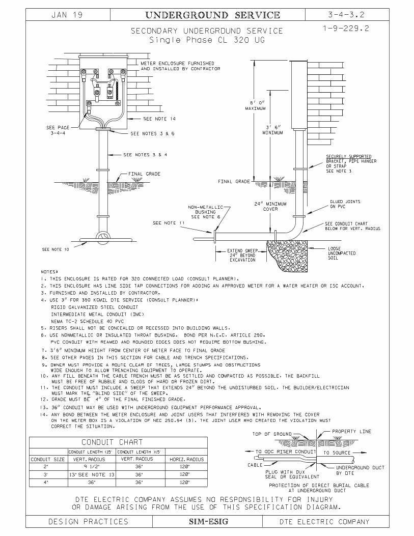
3-4-3.2UNDERGROUND SERVICE
SECONDARY UNDERGROUND SERVICE 1-9-229.2
TO SOURCE
CABLEUNDERGROUND DUCT
PROPERTY LINETOP OF GROUND
TO ODC RISER CONDUIT
PLUG WITH DUX
SEAL OR EQUIVALENT
AT UNDERGROUND DUCT
PROTECTION OF DIRECT BURIAL CABLE
Single Phase CL 320 UG
CONDUIT SIZE
CONDUIT CHART
2"
3"
4"
120"
120"
120"36" 36"
36"
36"
9 1/2"
CONDUIT LENGTH <15’ CONDUIT LENGTH >15’
SIM-ESIG
13" SEE NOTE 13
2. THIS ENCLOSURE HAS LINE SIDE TAP CONNECTIONS FOR ADDING AN APPROVED METER FOR A WATER HEATER OR ISC ACCOUNT.
3-4-4
SEE PAGE
3. FURNISHED AND INSTALLED BY CONTRACTOR.
5. RISERS SHALL NOT BE CONCEALED OR RECESSED INTO BUILDING WALLS.
INTERMEDIATE METAL CONDUIT (IMC)
RIGID GALVANIZED STEEL CONDUIT
NOTES:
8. SEE OTHER PAGES IN THIS SECTION FOR CABLE AND TRENCH SPECIFICATIONS.
6. USE NONMETALLIC OR INSULATED THROAT BUSHING. BOND PER N.E.C. ARTICLE 250.
SEE NOTES 3 & 4
SEE NOTES 3 & 6
FINAL GRADE
PVC CONDUIT WITH REAMED AND ROUNDED EDGES DOES NOT REQUIRE BOTTOM BUSHING.
METER ENCLOSURE FURNISHED
AND INSTALLED BY CONTRACTOR
NEMA TC-2 SCHEDULE 40 PVC
7. 3’6" MINIMUM HEIGHT FROM CENTER OF METER FACE TO FINAL GRADE
24" MINIMUM
COVER
SEE NOTE 11
FINAL GRADE
6’ 0"
MAXIMUM
3’ 6"
MINIMUM
SEE NOTE 10
13. 36" CONDUIT MAY BE USED WITH UNDERGROUND EQUIPMENT PERFORMANCE APPROVAL.
4. USE 3" FOR 350 KCMIL DTE SERVICE (CONSULT PLANNER):
SEE NOTE 14
9. OWNER MUST PROVIDE A ROUTE CLEAR OF TREES, LARGE STUMPS AND OBSTRUCTIONS
BELOW FOR VERT. RADIUS
SEE CONDUIT CHART
SOIL
UNCOMPACTED
LOOSE
EXCAVATION
24" BEYOND
EXTEND SWEEP
SEE NOTE 6
BUSHING
NON-METALLIC ON PVC
GLUED JOINTS
SEE NOTE 3
OR STRAP
BRACKET, PIPE HANGER
SECURELY SUPPORTED
WIDE ENOUGH TO ALLOW TRENCHING EQUIPMENT TO OPERATE.
14.
12. GRADE MUST BE 4" OF THE FINAL FINISHED GRADE.
MUST MARK THE "BLIND SIDE" OF THE SWEEP.
11. THE CONDUIT MUST INCLUDE A SWEEP THAT EXTENDS 24" BEYOND THE UNDISTURBED SOIL. THE BUILDER/ELECTRICIAN
MUST BE FREE OF RUBBLE AND CLODS OF HARD OR FROZEN DIRT.
10. ANY FILL BENEATH THE CABLE TRENCH MUST BE AS SETTLED AND COMPACTED AS POSSIBLE. THE BACKFILL
DTE ELECTRIC COMPANY ASSUMES NO RESPONSIBILITY FOR INJURY
OR DAMAGE ARISING FROM THE USE OF THIS SPECIFICATION DIAGRAM.
+-
CORRECT THE SITUATION.
ON THE METER BOX IS A VIOLATION OF NEC 250.94 (3). THE JOINT USER WHO CREATED THE VIOLATION MUST
ANY BOND BETWEEN THE METER ENCLOSURE AND JOINT USERS THAT INTERFERES WITH REMOVING THE COVER
1. THIS ENCLOSURE IS RATED FOR 320 CONNECTED LOAD (CONSULT PLANNER).

1-9-230
SIM-ESIG
UNDERGROUND SERVICE
OR DAMAGE ARISING FROM THE USE OF THIS SPECIFICATION DIAGRAM.
FACE WASHERALUMINUM BUS BAR
BELLEVILLE WASHER
INSTALL WITH TWO CRIMPS USINGANDERSON VERSA-CRIMP TOOL
FOR 4/0 NEUTRAL USE ALUMINUM TERMINAL ED. NO. 721-1302
USE ALUMINUM TERMINAL ED. NO. 721-1301
3/8’’ STEEL STUD MOUNTED
TO ALUMINUM BUS BAR
THESE ARE THE ONLY TERMINALS ACCEPTABLE FOR TERMINATING LINE SIDE CONDUCTORS
TERMINAL ASSEMBLY
NOTES:
USE ALUMINUM TERMINAL ED. NO. 721-1302
FOR 1/0 NEUTRAL USE ALUMINUM TERMINAL ED. NO. 721-1682
3-4-4
IN THE SINGLE PHASE CL 320 AND CL 200 - 2 POS HORIZONTAL ENCLOSURES
FEB 16
FOR 350 kcmil DTE SERVICES:
FOR 3/0 AWG DTE SERVICES:
DESIGN PRACTICES
1.
2.
DTE ELECTRIC LINE CREW
MATERIALS ABOVE ARE FURNISHED AND INSTALLED BY DTE ELECTRIC.
DTE ELECTRIC COMPANY ASSUMES NO RESPONSIBILITY FOR INJURY
DTE ELECTRIC COMPANY

SIM-ESIG
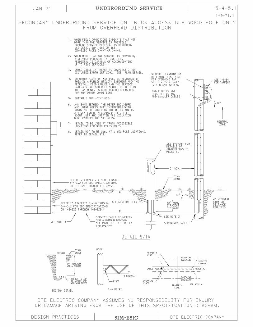
UNDERGROUND SERVICE 1-9-71
3-4-5
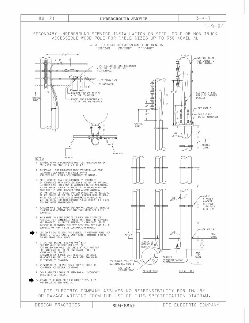
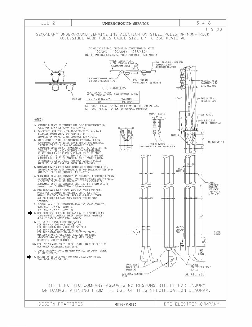
CABLE SIZE UP TO 350 KCMIL AL
STEEL POLES OR NON-TRUCK ACCESSIBLE WOOD POLES
SECONDARY UNDERGROUND SERVICE FROM OVERHEAD DISTRIBUTION ON
DTE ELECTRIC COMPANY ASSUMES NO RESPONSIBILITY FOR INJURY
DESIGN PRACTICES DTE ELECTRIC COMPANY
OR DAMAGE ARISING FROM THE USE OF THIS SPECIFICATION DIAGRAM.
JUL 21
PLAN DETAIL
RISER
TO PEDESTAL
HOUSE
9"
TRENCH
SECTION DETAIL
SEE NOTE 4
CABLE POLE PEDESTAL
CABLE COVER
24" MINIMUM
MINIMUM COVER
TO ASSURE 24"
TRENCH TO 30"
LINE
PROPERTY
LATERAL
SERVICE BOUNDARY
EASEMENT
LINE
PROPERTY
LINES
OVERHEAD BOUNDARY
EASEMENT
GRADE
FINAL
PEDESTAL
JOINT USE
3'
DETAIL 971
NOTE 7
12"
FOR TAPPING
SEE 1-9-84
DISTANCE
STRAIGHT
12" MIN.
REQUIRED
DISTANCE
STRAIGHT
4" MINIMUM
REQUIRED
CABLE GRIPS NOT
PEDESTAL
CONNECTIONS TO
DETAILS OF
SEE 1-9-231 FOR
SECONDARY CABLE
GRADE
FINAL
12-4-5 AND 12-4-6.
SEE SIM-ESIG PAGES-
FOR OVERHEAD TAP.
DETERMINE FUSE SIZE
SERVICE PLANNING TO
OR 1-9-226 THROUGH 1-9-229.1
3-4-3.2 FOR ODC SPECIFICATIONS
REFER TO SIM/ESIG 3-4-0 THROUGH
OR 1-9-226 THROUGH 1-9-229.1
3-4-3.2 FOR ODC SPECIFICATIONS
REFER TO SIM/ESIG 3-4-0 THROUGH
SEE 1-24-7.13
BRACKET
CABLE STANDOFF
3' MIN.
NOTE 6
12" MIN.
SEE NOTE 3
SEE NOTE 3
8'
9'
ZONE
NEUTRAL
6"
NOTE 6
SEE SECTION DETAIL
FOR POLICY
SEE PAGES 3-1-8 THRU 3-2-11
3/0 AL MINIMUM
SERVICE CABLE TO METER
BRACKET
ATTACH TO
JOINT USE TO
NOTES:
SIZES UP TO AND INCLUDING 350 KCMIL AL.
11. DETAIL SHALL ONLY BE USED FOR CABLE
SECONDARY CABLE ON STEEL POLES.
10. CABLE STANDOFF SHALL BE USED FOR ALL
IN NON-TRUCK ACCESSIBLE LOCATIONS.
9. ON WOOD POLES, DETAIL SHALL ONLY BE BUILT
MUST CORRECT THE SITUATION.
JOINT USER WHO CREATED THE VIOLATION
A VIOLATION OF NEC 250.94 (3). THE
REMOVING THE COVER ON THE METER BOX IS
AND JOINT USERS THAT INTERFERES WITH
8. ANY BOND BETWEEN THE METER ENCLOSURE
DETERMINED BY PLANNER.
STANDOFF BRACKETS. ACTUAL POLE SIZE SHOULD BE
MINIMUM CLASS 4 POLE SIZE REQUIRED FOR CABLE
MOUNT ON STEEL POLES.
HOLE AND BANDING FOR BOTTOM BRACKET HOLE TO
FOR THE BOTTOM HOLE. USE ONE 5/8" BOLT FOR TOP
FOR TOP MOUNTING HOLE AND 1/2" LAG
7. TO INSTALL BRACKET USE ONE 5/8" BOLT
INCHES ABOVE FINAL GRADE.
SWEEP. SWEEP SHALL PROTRUDE 4 TO 12
IF CUSTOMER RUNS 100% CONDUIT, INSTALL
6. INSTALL DUCT SEAL TO SEAL THE CABLES.
5. SUITABLE FOR JOINT USE.
FOR ANY OTHER CONDITIONS.
THE EASEMENT. SECURE RECORDED EASEMENT
LATERALS FOR OTHER LOTS WILL BE KEPT IN
PEDESTAL, FEED CABLES AND THE SERVICE
THIS IS A PUBLIC UTILITY EASEMENT AND THE
4. NO OTHER RIGHT-OF-WAY WILL BE REQUIRED IF
THE SWEEP REQUIREMENTS
FOR 100% CONDUIT PLEASE REFER TO 1-9-227
DISTURBED EARTH SETTLING. SEE PLAN DETAIL.
3. SNAKE CABLE IN TRENCH TO COMPENSATE FOR
UP TO FIVE SERVICES.
PESDESTAL IS CAPABLE OF ACCOMMODATING
A SERVICE PEDESTAL IS REQUIRED.
2. WHEN MORE THAN ONE SERVICE IS PROVIDED,
SIM-ESIG PAGES 3-4-7 OR 3-4-8.
USE DETAIL 984, 986 OR 988
THEN NO SERVICE PEDESTAL IS REQUIRED.
MORE THAN ONE SERVICE IS POSSIBLE,
1. WHEN FIELD CONDITIONS INDICATE THAT NOT

OCT 17
DESIGN PRACTICES DTE ELECTRIC COMPANYSIM-ESIG
UNDERGROUND SERVICE 3-4-6
GROUND PER
NEC ARTICLE 250
SUPPLIED AND
FOR 3/0 SINGLE PHASE SERVICE AND 3’’ CONDUIT FOR THREE
7. DTE ELECTRIC INSTALLED UG SERVICES REQUIRE 2’’ CONDUIT
DTE ELECTRIC COMPANY ASSUMES NO RESPONSIBILITY FOR INJURY
�’’ BOLTS AND WASHERS OR �’’ U-BOLTS OR PIPE HANGER
1 PH CL 200 FOR 100 TO 200 AMP SINGLE PHASE
1 PH CL 320 FOR 200 TO 320 AMP SINGLE PHASE
3 PH CL 200 FOR 100 TO 200 AMP THREE PHASE
OR DAMAGE ARISING FROM THE USE OF THIS SPECIFICATION DIAGRAM.
CLAMPS DESIGNED FOR THAT USE.
5. SUPPORT CHANNEL OR ANGLE IRON SHOULD BE BOLTED TO POST WITH
5-3-18 & 19
REFERENCE PAGE
9. ADDRESS MUST BE PERMANENTLY MARKED ON METER ENCLOSURE. USE
DISCONNECT IS SIZED, FURNISHED AND INSTALLED BY CUSTOMER.
4. SERVICE DISCONNECT AND RACEWAYS MUST BE RAINTIGHT. THE
THE POST MUST BE INSTALLED PLUMB AND REMAIN PLUMB AT ALL TIMES.
2. METER BOX MAY BE:
OR STRAP
HANGER
PIPE
2’
MA
X.
3’
MIN.
18’’
GRADE
NOTES:
6. RIGID AND IMC CONDUIT REQUIRE NONMETALLIC BUSHINGS WITH BONDING PER
6’ MAXIMUM TO TOP OF METER BOX.
MINIMUM
6’ MAXIMUM
3’ 6" MINIMUM HEIGHT TO CENTER OF METER FACE FROM GRADE AND
N.E.C. 250. PVC CONDUIT MUST BE TRIMMED TO REMOVE SHARP EDGES.
PERMANENT LETTERS OR STICKERS.
3’ 6"
1. ALL POST MOUNTED SERVICE EQUIPMENT IS OWNED AND MAINTAINED
BY THE CUSTOMER.
8. A SYSTEM GROUNDING ELECTRODE MUST BE INSTALLED IN COMPLIANCE WITH N.E.C. 250.
24’’ MINIMUM
COVER
5-3-5
5-3-6
CONDUIT NIPPLE
SEE NOTE 7
(PVC IMC OR RIGID)
BY CONTRACTOR
OR STRAP
HANGER
PIPE
SUPPORT CHANNEL1/2’’
TO STABILIZE
NECESSARY
WHEN
CONCRETE
DISCONNECT
SERVICE
WEATHERPROOF
GRADE
ELECTRODE
GROUNDING
APPROVED POSTS MINIMUM
2’’ GALVANIZED POST AND OTHERSUPPORT CHANNEL CAP
BOLT
SEE NOTE 6
METER ENCLOSURE
MUST BE SUITABLE FOR
OUTDOOR USE
GROUND PER NEC
ARTICLE 250
INSTALLED BY
CONTRACTOR
SEE NOTE 6
INSTALLED
SEE NOTE 2
2’’ OR 3’’ CONDUIT
3. USE 2’’ RIGID PIPE POST WITH CAP. WOOD POSTS ARE NOT ALLOWED.
11. THE USE OF POST MOUNT MUST BE APPROVED BY LOCAL BUILDING INSPECTOR.
FARMS OR ANY LOCATION THAT REQUIRES A REMOTE METER
100-320 AMP SINGLE PHASE OR 100 TO 200 AMP THREE PHASE
POST MOUNTED UNDERGROUND SERVICE
USED FOR INDIVIDUAL MOBILE HOMES, SEWER LIFT STATIONS,
SEE NOTES 2 & 12
PHASE 3/0 SERVICES.
AND EASE OF ACCESS.
OUTSIDE OF DTE EASEMENT). ALL LOCATIONS MUST BE CLEAR OF DEBRIS OR BUSHES
BE IN ONE OF REAR CORNERS OF THE PROPERTY (EITHER OPTION MUST BE
TRANSFORMER. IF A POLE DOES NOT EXIST ON PROPERTY, THE POST MOUNT SHOULD
10. THE POST MOUNT SHOULD BE INSTALLED CLOSE TO THE SOURCE POLE OR PAD MOUNT
CREATED THE VIOLATION MUST CORRECT THE SITUATION.
THE COVER ON THE METER BOX IS A VIOLATION OF NEC 250.94 (3). THE JOINT USER WHO
12. ANY BOND BETWEEN THE METER ENCLOSURE AND JOINT USERS THAT INTERFERES WITH REMOVING
DESIGN PRACTICES DTE ELECTRIC COMPANYSIM-ESIG
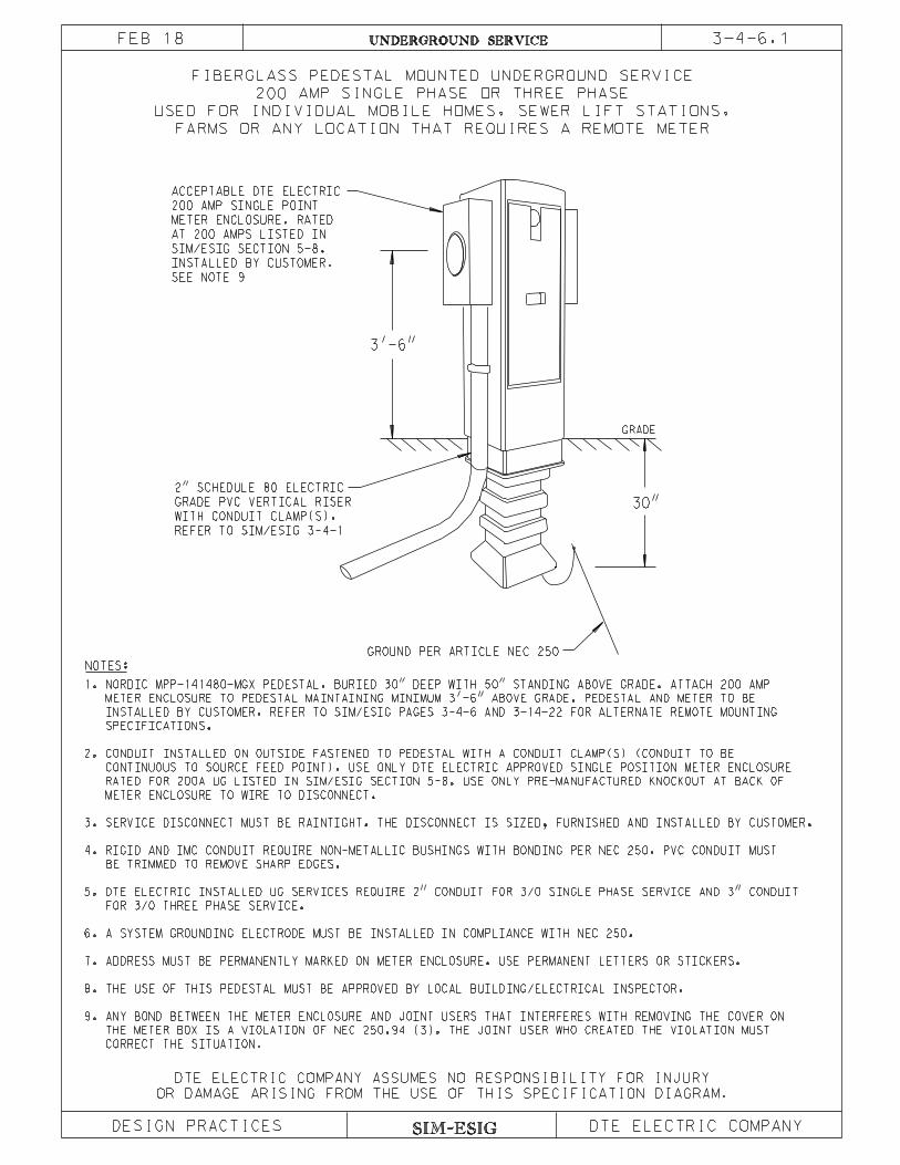
UNDERGROUND SERVICEFEB 18
OR DAMAGE ARISING FROM THE USE OF THIS SPECIFICATION DIAGRAM.
DTE ELECTRIC COMPANY ASSUMES NO RESPONSIBILITY FOR INJURY
FARMS OR ANY LOCATION THAT REQUIRES A REMOTE METER
USED FOR INDIVIDUAL MOBILE HOMES, SEWER LIFT STATIONS,
200 AMP SINGLE PHASE OR THREE PHASE
FIBERGLASS PEDESTAL MOUNTED UNDERGROUND SERVICE
3-4-6.1
GRADE
3’-6"
30"
GROUND PER ARTICLE NEC 250
NOTES:
REFER TO SIM/ESIG 3-4-1
WITH CONDUIT CLAMP(S).
GRADE PVC VERTICAL RISER
2" SCHEDULE 80 ELECTRIC
CORRECT THE SITUATION.
THE METER BOX IS A VIOLATION OF NEC 250.94 (3). THE JOINT USER WHO CREATED THE VIOLATION MUST
9. ANY BOND BETWEEN THE METER ENCLOSURE AND JOINT USERS THAT INTERFERES WITH REMOVING THE COVER ON
8. THE USE OF THIS PEDESTAL MUST BE APPROVED BY LOCAL BUILDING/ELECTRICAL INSPECTOR.
7. ADDRESS MUST BE PERMANENTLY MARKED ON METER ENCLOSURE. USE PERMANENT LETTERS OR STICKERS.
6. A SYSTEM GROUNDING ELECTRODE MUST BE INSTALLED IN COMPLIANCE WITH NEC 250.
FOR 3/0 THREE PHASE SERVICE.
5. DTE ELECTRIC INSTALLED UG SERVICES REQUIRE 2" CONDUIT FOR 3/0 SINGLE PHASE SERVICE AND 3" CONDUIT
BE TRIMMED TO REMOVE SHARP EDGES.
4. RIGID AND IMC CONDUIT REQUIRE NON-METALLIC BUSHINGS WITH BONDING PER NEC 250. PVC CONDUIT MUST
3. SERVICE DISCONNECT MUST BE RAINTIGHT. THE DISCONNECT IS SIZED, FURNISHED AND INSTALLED BY CUSTOMER.
METER ENCLOSURE TO WIRE TO DISCONNECT.
RATED FOR 200A UG LISTED IN SIM/ESIG SECTION 5-8. USE ONLY PRE-MANUFACTURED KNOCKOUT AT BACK OF
CONTINUOUS TO SOURCE FEED POINT). USE ONLY DTE ELECTRIC APPROVED SINGLE POSITION METER ENCLOSURE
2. CONDUIT INSTALLED ON OUTSIDE FASTENED TO PEDESTAL WITH A CONDUIT CLAMP(S) (CONDUIT TO BE
SPECIFICATIONS.
INSTALLED BY CUSTOMER. REFER TO SIM/ESIG PAGES 3-4-6 AND 3-14-22 FOR ALTERNATE REMOTE MOUNTING
METER ENCLOSURE TO PEDESTAL MAINTAINING MINIMUM 3’-6" ABOVE GRADE. PEDESTAL AND METER TO BE
1. NORDIC MPP-141480-MGX PEDESTAL. BURIED 30" DEEP WITH 50" STANDING ABOVE GRADE. ATTACH 200 AMP
SEE NOTE 9
INSTALLED BY CUSTOMER.
SIM/ESIG SECTION 5-8.
AT 200 AMPS LISTED IN
METER ENCLOSURE. RATED
200 AMP SINGLE POINT
ACCEPTABLE DTE ELECTRIC


SIM-ESIG
3-4-11UNDERGROUND SERVICE
POSITIONING CONDUCTORS ON CABLE POLE
SERVICE CONDUCTOR IDENTIFICATION
DESIGN PRACTICES
OR DAMAGE ARISING FROM THE USE OF THIS SPECIFICATION DIAGRAM.
NOTE:
1-9-93
PRIMARY AND SECONDARY CABLE LOCATION AT CABLE POLE
TELEPHONE GROUNDPOWER
WHO WILL COORDINATE WITH THE TELEPHONE COMPANY ON JOINT USE POLES.
AND WORKING SPACE AND WILL BE ASSIGNED BY THE SERVICE PLANNER
THE POLE QUADRANT LOCATIONS SHOWN ARE TO ASSURE PROPER CLIMBING
CHOICE
SECOND
CHOICE
FIRST
FACE OF POLE
SPACE
CLIMBING
OBSTRUCTED
CROSSARM
FIRST CHOICE SECOND CHOICE TRANSFORMER POLE
SERVICE CONDUCTOR IDENTIFICATION
NOT STRIPPED
OPPOSITE THE GUY.
PRIMARY CUSTOMER AND URD CABLES WILL BE INSTALLED ON THE SIDE
ON ALL PRIMARY DEADEND POLES, CABLES FOR ALL NEW COMMERCIAL FEEDER,
FEB 16
DTE SECONDARY
DTE SECONDARY
DTE ELECTRIC COMPANY ASSUMES NO RESPONSIBILITY FOR INJURY
DTE ELECTRIC COMPANY
L’ OR W’ CONDUCTORS
BLUE TAPE
P’ CONDUCTOR
G’ CONDUCTOR
WHITE TAPE
ORANGE OR RED TAPE
(BLUE TAPE)
L’ OR W’ CONDUCTORS

SIM-ESIG
3-5-11UNDERGROUND SERVICE
WIRE SIZE #8 THRU #2 AWG
TEMPORARY SERVICE PEDESTAL INSTALLATION
DESIGN PRACTICES
E. TEMPORARY SERVICE PEDESTAL SHOULD NOT BE INSTALLED IN UTILITY EASEMENT.
A. REFER TO SIM-ESIG PAGE 3-5-15 FOR INFORMATION RELATING TO UG SERVICE.
3-12-4.
MOUNT WHEN APPROVED BY SERVICE PLANNER. SEE PAGE 1-9-225/SIM-ESIG PAGES 3-12-1 THRU
5. LISTED UG CABLE FURNISHED AND INSTALLED BY CONTRACTOR.
1-9-241
LEGEND:
3. CONTRACTOR TO FURNISH:
12’’ BELOW GRADE TO THE 2’’ OPENING IN THE BASE OF THE SECONDARY COMPARTMENT.
WASHERS TO FIT A 2’’ OPENING.
FLEXIBLE METAL CONDUIT.
PEDESTAL.
6. CONDUIT FURNISHED AND INSTALLED BY CONTRACTOR.
SIM-ESIG PAGE 3-5-12 FOR CONSTRUCTION DETAILS. ALTERNATE PRECONSTRUCTION METER
7. TEMPORARY SERVICE PEDESTAL FURNISHED AND INSTALLED BY CONTRACTOR. SEE PAGE 1-9-242/
NOTES:
B. LINE CONDUCTORS MAY ENTER METER ENCLOSURE THROUGH BOTTOM OF CABINET.
C. LOAD CONDUCTORS MAY LEAVE METER ENCLOSURE THROUGH BOTTOM OR BACK OF CABINET.
D. THE ELECTRICAL CONTRACTOR WILL BE RESPONSIBLE FOR LEAVING SUFFICIENT CABLE TO ALLOW
OR
4’’ MAX.
2
4
3
1
OR
4
3
5
4’’ MAX.12’’
24’’
12’’
FIRM SOIL
3’ MINIMUM IN
GRADE LEVEL
BY CONTRACTOR
FURNISHED AND INSTALLED
NEC APPROVED GROUND
76
SHALL APPLY ONLY TO TEMPORARY SERVICES.
THE SPECIFICATION CONTAINED HEREIN
A. FOR TRANSFORMER ONLY OPTION - LIQUIDTIGHT FLEXIBLE METAL CONDUIT INSTALLED ON CABLE FROM
B. FOR TRANSFORMER ONLY OPTION - A LIQUIDTIGHT FLEXIBLE METAL CONDUIT FITTING WITH REDUCER
C. FOR TRANSFORMER OR PEDESTAL OPTION - 4 FEET OF CABLE BEYOND THE END OF THE LIQUIDTIGHT
1. DTE ELECTRIC TRANSFORMER.
4. DTE ELECTRIC TO INSTALL AND TERMINATE CUSTOMER’S UG CABLE IN TRANSFORMER OR
DTE ELECTRIC COMPANY
SERVICE CONNECTIONS WILL BE MADE TO TRANSFORMER ONLY WHEN NO PEDESTAL EXISTS
NOTE:
2. DTE ELECTRIC SECONDARY PEDESTAL.
F
F.
OR DAMAGE ARISING FROM THE USE OF THIS SPECIFICATION DIAGRAM.
DTE ELECTRIC COMPANY ASSUMES NO RESPONSIBILITY FOR INJURY
OCT 17
ANY BOND BETWEEN THE METER ENCLOSURE AND JOINT USERS THAT INTERFERES WITH REMOVING THE
COVER ON THE METER BOX IS A VIOLATION OF NEC 250.94 (3). THE JOINT USER WHO CREATED THE
VIOLATION MUST CORRECT THE SITUATION.
4 FEET INSIDE THE TRANSFORMER OR PEDESTAL.

SIM-ESIG
UNDERGROUND SERVICE
WIRE SIZE #8 THRU #2
TEMPORARY SERVICE PEDESTAL
DESIGN PRACTICES
OR DAMAGE ARISING FROM THE USE OF THIS SPECIFICATION DIAGRAM.
3-5-12OCT 17
DTE ELECTRIC COMPANY ASSUMES NO RESPONSIBILITY FOR INJURY
DTE ELECTRIC COMPANY
G. ANY BOND BETWEEN THE METER ENCLOSURE
AND JOINT USERS THAT INTERFERES WITH
REMOVING THE COVER ON THE METER BOX
IS A VIOLATION OF NEC 250.94 (3).
THE JOINT USER WHO CREATED THE
VIOLATION MUST CORRECT THE SITUATION.
42’’ MIN.
6’ MAX.
1-9-242
SEE PAGE 3-4-6
LARGER THAN #2,
FOR 30 SERVICES AND 10 SERVICES
SHALL APPLY ONLY TO TEMPORARY SERVICES.
THE SPECIFICATION CONTAINED HEREIN
FOR POWER OUTLET
ALTERNATE LOCATION
LEGEND :
5. CONDUIT SUPPORT CLAMP.
4. POWER OUTLET CABINET FURNISHED
3. CONDUIT WITH BUSHINGS FURNISHED
CONVENIENCE) OR EQUIVALENT.
1. UNISTRUT P-1000 (NUMBER SHOWN FOR
INSTALLATION.
F. REFER TO SIM-ESIG PAGE 3-5-11 FOR
THROUGH BOTTOM OR OUT BACK OF
E. LOAD CONDUCTORS MAY BE INSTALLED
D. LINE CONDUCTORS MAY BE INSTALLED
C. DO NOT LOCATE PEDESTAL IN EASEMENT.
B. ANGLE BRACING MAY BE USED IF
A. POST OR STAKE MAY BE DRIVEN OR
GRADE
3
FIRM SOIL
3’-0’’ MIN. IN
1
5
4
3
2
NOTES :
2. 1 PHASE CL 200 METER ENCLOSURE
FURNISHED AND INSTALLED BY CONTRACTOR.
G
CONSTRUCTION FURNISHED AND INSTALLED
BY CONTRACTOR.
AND INSTALLED BY CONTRACTOR.
AND INSTALLED BY CONTRACTOR.
AUGERED.
DESIRED.
THROUGH BOTTOM OF METER ENCLOSURE.
METER ENCLOSURE.
UNDERGROUND SERVICE 3-5-15FEB 16
INSTALLATION PROCEDURE FOR SECONDARY METERED SERVICE
The following instructions are for the customer’s contractor in those situations where DTEElectric policy or Michigan Public Service Commission (MPSC) rules require customerinstallation of underground secondary service conductors.
The type and location of distribution equipment is a DTE Electric Planner decision based on thesize of the customer’s load and the distribution facilities available.
1. Work Around Secondary Power Sources.
(a) Equipment Access. Only DTE Electric personnel or authorized DTE contractorsmay open transformers and service pedestals or work above the ten-foot level on DTEElectric poles.
(b) Digging in Easements. In those cases where the customer’s contractor is required toinstall the secondary service conductors to the distribution equipment, the contractorwill hand dig in the easement to the customer’s property line. The contractor willalways notify Miss Dig to stake the location of any underground facilities beforebeginning work. The contractor will not excavate more than 30 inches below grade ordo any machine excavating in an easement or within 3 feet of a power source. If theroute of the cable must cross another party’s property or onto public property,arrangements must be made with the DTE Electric Planner for completion of thatportion by DTE Electric crews.
(c) Adequate Cable Length. The electrical contractor will be responsible for leavingsufficient cable at the source for proper termination by DTE Electric personnel.Specifically, 6 feet of extra cable is required inside a transformer or pedestal and 5feet beyond the secondary rack on a secondary cable pole. Since the contractor willgenerally not install the cable into the equipment or all the way up the pole, somejudgment will be necessary. In some cases, the DTE Electric Planner may find itnecessary to alter these dimensions. In any case, where it is not clear, the contractorshould consult with the DTE Electric Planner.
2. Contractor Instructions.
At the source, the contractor will proceed according to one of the following situations:
(a) Padmount Transformer--Energized.
(1) Direct buried. Trench to the transformer, hand digging the last three feet, butmake no attempt to tunnel underneath. Leave sufficient cable to properlyterminate in the transformer.
(2) Existing conduit. Arrange for DTE Electric crews to assist in pulling cable intothe transformer.
(3) Conduit to be installed. Trench and install conduit to within three feet of thetransformer. DTE Electric crews will assist in installing the last three feet ofconduit, the sweep, and in pulling the cable.
SIM-ESIG SIM-ESIG: 3-5
UNDERGROUND SERVICE 3-5-16FEB 16
(b) Padmount Transformer--Not Energized.
The electrical contractor will bring sufficient cable underneath the transformer padand into the secondary compartment for DTE Electric personnel to properly terminate.The DTE Electric Planner will arrange to unlock the transformer and will beresponsible for locking it when the contractor’s work is complete.
(c) Padmount Transformer--Not on Job Site.
The electrical contractor will bring sufficient cable up into the secondary window areaof the padmount foundation for DTE Electric personnel to properly terminate.
(d) Pedestals.
The electrical contractor will trench to the pedestal, hand digging the last three feet,and leave sufficient cable for DTE Electric personnel to properly terminate.
(e) One or Two Services from a Pole.
The electrical contractor will bring the cable to the pole quadrant designated by theDTE Electric Planner and provide conduit to ten feet above grade. The contractorwill leave sufficient cable to reach 5 feet beyond the secondary rack or as directed bythe DTE Electric Planner. DTE Electric personnel will train and cover the cableabove the ten-foot level and connect to the overhead secondary source. (See page 3-4-7.)
Before instructing an electrical contractor to install service for training up a pole,consideration should be given to possible future services. If it appears that more thantwo single conductor per phase underground services may be brought to this pole, theDTE Electric Planner should arrange for installation of a pedestal as described below.
(f) More than Two Services from a Pole.
DTE Electric will furnish and install a secondary connection pedestal in the easementfor terminating up to five services. Edison personnel will furnish and install thesupply cable to the pedestal and connect to the overhead secondary source as shownon page 3-4-5. The electrical contractor will proceed as described in (d) above. TheDTE Electric Planner will specify the location of the pedestal as follows:
(1) The pedestal will be located in the easement on the property of one of thecustomers requesting service, preferably at the corner of the lot.
(2) Every effort should be made to avoid installing the pedestal on the sameproperty as the overhead distribution pole.
SIM-ESIG SIM-ESIG: 3-5
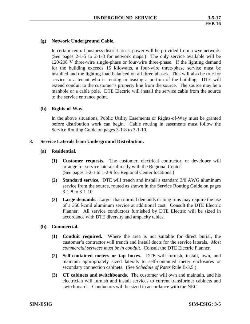
UNDERGROUND SERVICE 3-5-17FEB 16
(g) Network Underground Cable.
In certain central business district areas, power will be provided from a wye network.(See pages 2-1-5 to 2-1-8 for network maps.) The only service available will be120/208 V three-wire single-phase or four-wire three-phase. If the lighting demandfor the building exceeds 15 kilowatts, a four-wire three-phase service must beinstalled and the lighting load balanced on all three phases. This will also be true forservice to a tenant who is renting or leasing a portion of the building. DTE willextend conduit to the customer’s property line from the source. The source may be amanhole or a cable pole. DTE Electric will install the service cable from the sourceto the service entrance point.
(h) Rights-of-Way.
In the above situations, Public Utility Easements or Rights-of-Way must be grantedbefore distribution work can begin. Cable routing in easements must follow theService Routing Guide on pages 3-1-8 to 3-1-10.
3. Service Laterals from Underground Distribution.
(a) Residential.
(1) Customer requests. The customer, electrical contractor, or developer willarrange for service laterals directly with the Regional Center.(See pages 1-2-1 to 1-2-9 for Regional Center locations.)
(2) Standard service. DTE will trench and install a standard 3/0 AWG aluminumservice from the source, routed as shown in the Service Routing Guide on pages3-1-8 to 3-1-10.
(3) Large demands. Larger than normal demands or long runs may require the useof a 350 kcmil aluminum service at additional cost. Consult the DTE ElectricPlanner. All service conductors furnished by DTE Electric will be sized inaccordance with DTE diversity and ampacity tables.
(b) Commercial.
(1) Conduit required. Where the area is not suitable for direct burial, thecustomer’s contractor will trench and install ducts for the service laterals. Mostcommercial services must be in conduit. Consult the DTE Electric Planner.
(2) Self-contained meters or tap boxes. DTE will furnish, install, own, andmaintain appropriately sized laterals to self-contained meter enclosures orsecondary connection cabinets. (See Schedule of Rates Rule B-3.5.)
(3) CT cabinets and switchboards. The customer will own and maintain, and hiselectrician will furnish and install services to current transformer cabinets andswitchboards. Conductors will be sized in accordance with the NEC.
SIM-ESIG SIM-ESIG: 3-5

UNDERGROUND SERVICE 3-5-18FEB 16
4. Underground Service from Overhead Distribution.
(a) Residential. Under MPSC rules, all new, relocated or upgraded residentialservice connections will be installed as underground residential service lateral atthe customer’s expense. Therefore, it is necessary for the Company to adapt theoverhead distribution system to supply an underground service.
(b) Commercial. Underground secondary service laterals may be served directly fromoverhead distribution if the existing overhead facilities have adequate capacity toserve the additional load. Consult the DTE Electric Planner.
SIM-ESIG SIM-ESIG: 3-5
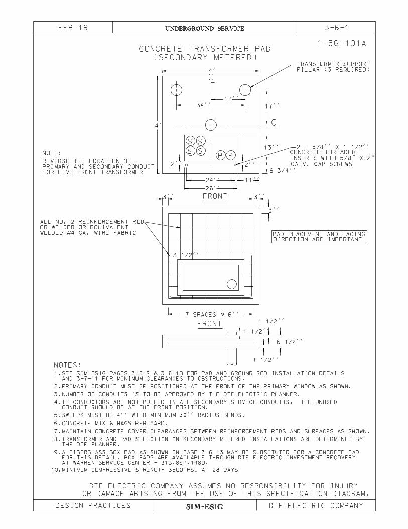
NOTES:
AT WARREN SERVICE CENTER - 313.897.1480.
MAINTAIN CONCRETE COVER CLEARANCES BETWEEN REINFORCEMENT RODS AND SURFACES AS SHOWN.
SWEEPS MUST BE 4’’ WITH MINIMUM 36’’ RADIUS BENDS.
IF CONDUCTORS ARE NOT PULLED IN ALL SECONDARY SERVICE CONDUITS, THE UNUSED
CONDUIT SHOULD BE AT THE FRONT POSITION.
PRIMARY CONDUIT MUST BE POSITIONED AT THE FRONT OF THE PRIMARY WINDOW AS SHOWN.
AND 3-7-11 FOR MINIMUM CLEARANCES TO OBSTRUCTIONS.
SEE SIM-ESIG PAGES 3-6-9 & 3-6-10 FOR PAD AND GROUND ROD INSTALLATION DETAILS1.
2.
3.
4.
5.
6.
7.
8.
9.
TRANSFORMER AND PAD SELECTION ON SECONDARY METERED INSTALLATIONS ARE DETERMINED BY
CONCRETE MIX 6 BAGS PER YARD.
10.MINIMUM COMPRESSIVE STRENGTH 3500 PSI AT 28 DAYS
A FIBERGLASS BOX PAD AS SHOWN ON PAGE 3-6-13 MAY BE SUBSITUTED FOR A CONCRETE PAD
NUMBER OF CONDUITS IS TO BE APPROVED BY THE DTE ELECTRIC PLANNER.
FOR THIS DETAIL. BOX PADS ARE AVAILABLE THROUGH DTE ELECTRIC INVESTMENT RECOVERY
THE DTE PLANNER.
SIM-ESIG
3-6-1UNDERGROUND SERVICE
(SECONDARY METERED)
CONCRETE TRANSFORMER PAD
DESIGN PRACTICES
OR DAMAGE ARISING FROM THE USE OF THIS SPECIFICATION DIAGRAM.
FRONT
FRONT
PPSS
SS
3 1/2’’
7 SPACES @ 6’’
1 1/2’’
1 1/2’’
1 1/2’’
6 1/2’’
3’’
3’’3’’
NOTE:
11’’
26’’
24’’
6 3/4’’
13’’
2’’2’’
4’
34’’ 17’’
4’
OR WELDED OR EQUIVALENT
ALL NO. 2 REINFORCEMENT ROD
FOR LIVE FRONT TRANSFORMER
PRIMARY AND SECONDARY CONDUIT
REVERSE THE LOCATION OF
DIRECTION ARE IMPORTANTPAD PLACEMENT AND FACING
INSERTS WITH 5/8" X 2"
CONCRETE THREADED2 - 5/8’’ X 1 1/2’’
PILLAR (3 REQUIRED)
TRANSFORMER SUPPORT
1-56-101A
CL
LC
17’’
WELDED #4 GA. WIRE FABRIC
GALV. CAP SCREWS
FEB 16
DTE ELECTRIC COMPANY ASSUMES NO RESPONSIBILITY FOR INJURY
DTE ELECTRIC COMPANY
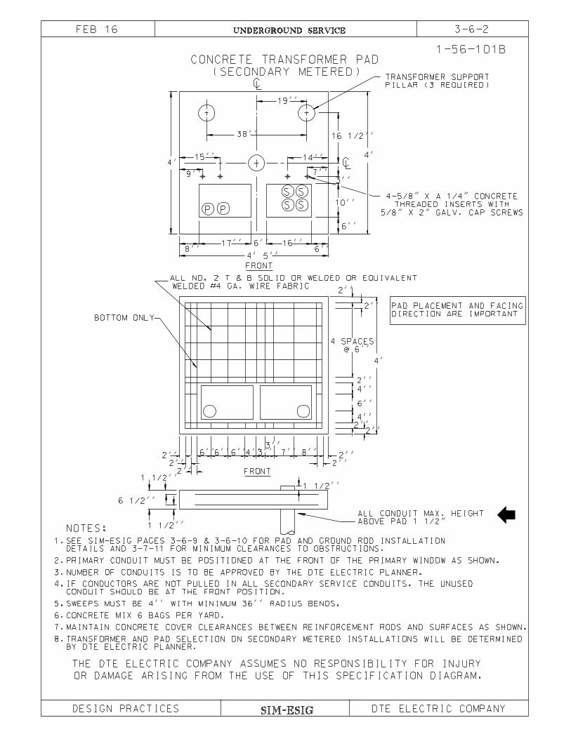
SIM-ESIG
UNDERGROUND SERVICE
(SECONDARY METERED)
CONCRETE TRANSFORMER PAD
OR DAMAGE ARISING FROM THE USE OF THIS SPECIFICATION DIAGRAM.
FRONT
FRONT
1-56-101B
1 1/2’’
1 1/2’’
6 1/2’’
1 1/2’’
4’
4’
@ 6’’
4 SPACES
BOTTOM ONLY
2’’2’’4’’
4’’
6’’
2’’
8’’3’’
4’’
2’’
2’’ 3’’
2’’
2’’6’’6’’ 7’’
2’’
2’’
2’’
6’’
15’’
9’’
8’’
WELDED #4 GA. WIRE FABRIC
ALL NO. 2 T & B SOLID OR WELDED OR EQUIVALENT
6’’
4’ 5’’
17’’ 16’’6’’
3’’
7’’
14’’
S S
SS
PP10’’
6’’
19’’
16 1/2’’38’’
NOTES:
TRANSFORMER AND PAD SELECTION ON SECONDARY METERED INSTALLATIONS WILL BE DETERMINED
MAINTAIN CONCRETE COVER CLEARANCES BETWEEN REINFORCEMENT RODS AND SURFACES AS SHOWN.
CONCRETE MIX 6 BAGS PER YARD.
SWEEPS MUST BE 4’’ WITH MINIMUM 36’’ RADIUS BENDS.
IF CONDUCTORS ARE NOT PULLED IN ALL SECONDARY SERVICE CONDUITS, THE UNUSED
CONDUIT SHOULD BE AT THE FRONT POSITION.
PRIMARY CONDUIT MUST BE POSITIONED AT THE FRONT OF THE PRIMARY WINDOW AS SHOWN.
DETAILS AND 3-7-11 FOR MINIMUM CLEARANCES TO OBSTRUCTIONS.
SEE SIM-ESIG PAGES 3-6-9 & 3-6-10 FOR PAD AND GROUND ROD INSTALLATION
4’
DIRECTION ARE IMPORTANT
PAD PLACEMENT AND FACING
PILLAR (3 REQUIRED)
TRANSFORMER SUPPORT
CL
LC
1.
2.
3.
4.
5.
6.
7.
8.
5/8" X 2" GALV. CAP SCREWS
THREADED INSERTS WITH
4-5/8" X A 1/4" CONCRETE
ABOVE PAD 1 1/2"
ALL CONDUIT MAX. HEIGHT
3-6-2FEB 16
DESIGN PRACTICES
NUMBER OF CONDUITS IS TO BE APPROVED BY THE DTE ELECTRIC PLANNER.
BY DTE ELECTRIC PLANNER.
THE DTE ELECTRIC COMPANY ASSUMES NO RESPONSIBILITY FOR INJURY
DTE ELECTRIC COMPANY

9.MINIMUM COMPRESSIVE STRENGTH 3500 PSI AT 28 DAYS
SIM-ESIG
3-6-3UNDERGROUND SERVICE
(SECONDARY METERED)
CONCRETE TRANSFORMER PAD
OR DAMAGE ARISING FROM THE USE OF THIS SPECIFICATION DIAGRAM.
AND 3-7-11 FOR MINIMUM CLEARANCES TO OBSTRUCTIONS.
SWEEPS MUST BE 4’’ WITH MINIMUM 36’’ RADIUS BENDS.
MAINTAIN CONCRETE COVER CLEARANCES BETWEEN REINFORCEMENT RODS AND SURFACES AS SHOWN.
WELDED #4 GA. WIRE FABRIC
OR WELDED OR EQUIVALENT
ALL No. 2 REINFORCEMENT ROD
ONLY
LAYER
BOTTOM
No. 2
No. 2 BAR
BARS
INSERTS WITH 5/8’’ X 2’’ GALV. CAP SCREWS
TWO 5/8’’ X 1-1/2’’ CONCRETE THREADED
TRANSFORMER SUPPORT PILLAR,
FRONT
1 1/2’’
1 1/2’’
6 1/2’’
1 1/2’’
6’’
C
5’-2’’8’’
20"
19’’
12’’
58’’
29’’
12’’
6’’
6’-2’’
12’’18’’18’’12’’
S S S
SSSPP
2’’ 2’’2’’1’’
2’’2’’
18’’12’’ 12’’
3’’3’’
6’’6’’
3’’
NOTES:
IF CONDUCTORS ARE NOT PULLED IN ALL SECONDARY SERVICE CONDUITS, THE UNUSED CONDUIT
SHOULD BE AT THE FRONT POSITION.
PRIMARY CONDUIT MUST BE POSITIONED AT THE FRONT OF THE PRIMARY WINDOW AS SHOWN.
SEE SIM-ESIG PAGES 3-6-9 & 3-6-10 FOR PAD AND GROUND ROD INSTALLATION DETAILS
DIRECTION ARE IMPORTANT
PAD PLACEMENT AND FACING
L
CL
1-56-102A
S
S
1.
2.
3.
4.
5.
6.
7.
8.
3 REQUIRED @ 6’’
ALL CONDUIT MAX. HEIGHT
ABOVE PAD 1 1/2"
TRANSFORMER AND PAD SELECTION ON SECONDARY METERED INSTALLATIONS ARE DETERMINED BY
CONCRETE MIX 6 BAGS PER YARD.
14’’
3’’
FEB 16
DESIGN PRACTICES
NUMBER OF CONDUITS IS TO BE APPROVED BY DTE ELECTRIC PLANNER.
DTE ELECTRIC PLANNER.
DTE ELECTRIC COMPANY ASSUMES NO RESPONSIBILITY FOR INJURY
DTE ELECTRIC COMPANY
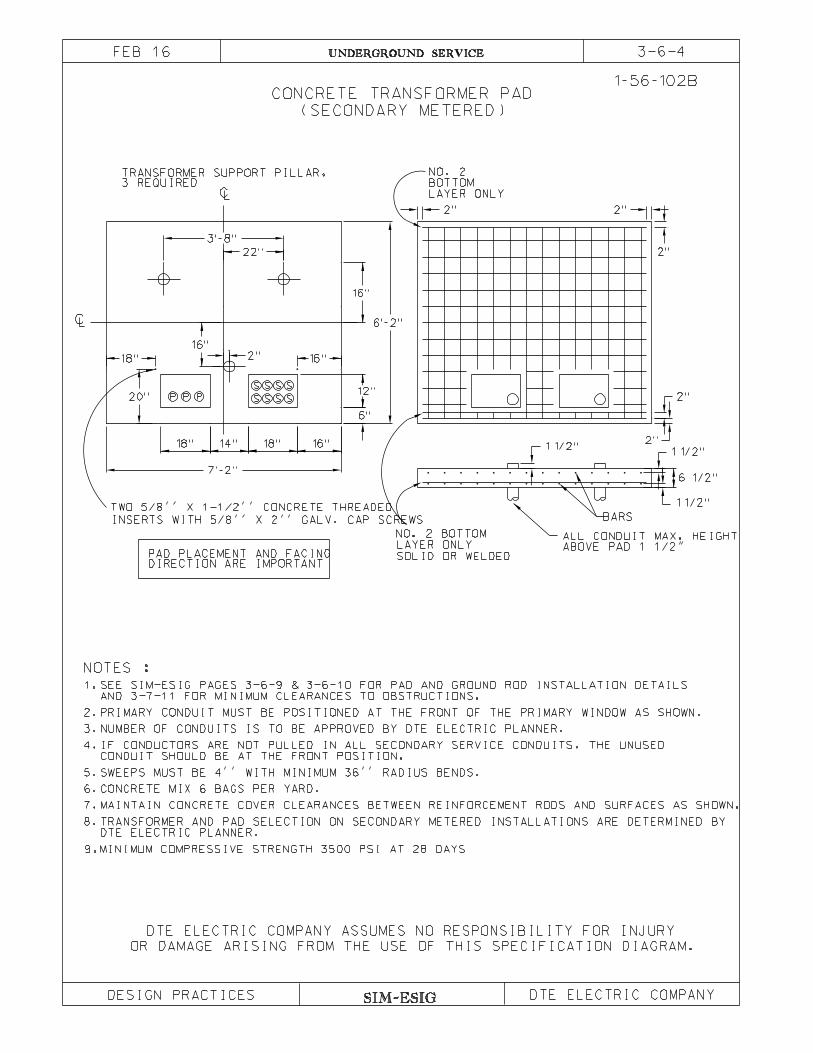
SIM-ESIG
UNDERGROUND SERVICE
OR DAMAGE ARISING FROM THE USE OF THIS SPECIFICATION DIAGRAM.
(SECONDARY METERED)
CONCRETE TRANSFORMER PAD
PRIMARY CONDUIT MUST BE POSITIONED AT THE FRONT OF THE PRIMARY WINDOW AS SHOWN.
SEE SIM-ESIG PAGES 3-6-9 & 3-6-10 FOR PAD AND GROUND ROD INSTALLATION DETAILS
LAYER ONLY
NO. 2 BOTTOM
MAINTAIN CONCRETE COVER CLEARANCES BETWEEN REINFORCEMENT RODS AND SURFACES AS SHOWN.
IF CONDUCTORS ARE NOT PULLED IN ALL SECONDARY SERVICE CONDUITS, THE UNUSED
NOTES :
AND 3-7-11 FOR MINIMUM CLEARANCES TO OBSTRUCTIONS.
DIRECTION ARE IMPORTANTPAD PLACEMENT AND FACING
CONDUIT SHOULD BE AT THE FRONT POSITION.
SWEEPS MUST BE 4’’ WITH MINIMUM 36’’ RADIUS BENDS.
2.
7.
8.
6.
5.
4.
3.
1.
TRANSFORMER SUPPORT PILLAR,3 REQUIRED
1-56-102B
LC
S
S
7’-2’’
PP P S
S
S S
S S
CL
NO. 2
LAYER ONLY
BOTTOM
TWO 5/8’’ X 1-1/2’’ CONCRETE THREADED
INSERTS WITH 5/8’’ X 2’’ GALV. CAP SCREWS
1 1/2’’
12’’
6’’
BARS
18’’ 14’’ 18’’ 16’’1 1/2’’
6 1/2’’
1 1/2’’
2’’
2’’
2’’
2’’2’’
22’’
3’-8’’
16’’2’’
16’’
18’’
20’’
16’’
6’-2’’
ALL CONDUIT MAX. HEIGHTABOVE PAD 1 1/2"
SOLID OR WELDED
TRANSFORMER AND PAD SELECTION ON SECONDARY METERED INSTALLATIONS ARE DETERMINED BY
CONCRETE MIX 6 BAGS PER YARD.
9.MINIMUM COMPRESSIVE STRENGTH 3500 PSI AT 28 DAYS
3-6-4FEB 16
DESIGN PRACTICES
NUMBER OF CONDUITS IS TO BE APPROVED BY DTE ELECTRIC PLANNER.
DTE ELECTRIC PLANNER.
DTE ELECTRIC COMPANY ASSUMES NO RESPONSIBILITY FOR INJURY
DTE ELECTRIC COMPANY

03-06-05.dgn 09-Jul-2020 14:52 /u31121
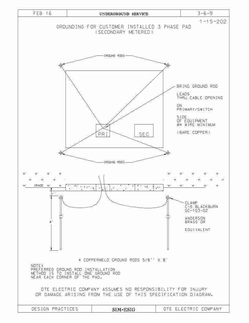
SIM-ESIG
3-6-9UNDERGROUND SERVICE
DESIGN PRACTICES
OR DAMAGE ARISING FROM THE USE OF THIS SPECIFICATION DIAGRAM.
8’
1’’
GRADE
GROUND RODS
GROUND RODS
PRI
EQUIVALENT
BRASS OR
ANDERSON
GC-103-02
C-5 BLACKBURN
CLAMP
4 COPPERWELD GROUND RODS 5/8’’ X 8’
(BARE COPPER)
#4 WIRE MINIMUM
OF EQUIPMENT
SIDE
PRIMARY/SWITCH
ON
THRU CABLE OPENING
LEADS
BRING GROUND ROD
SEC
1-15-202
GROUNDING FOR CUSTOMER INSTALLED 3 PHASE PAD
(SECONDARY METERED)
FEB 16
DTE ELECTRIC COMPANY ASSUMES NO RESPONSIBILITY FOR INJURY
DTE ELECTRIC COMPANY
NEAR EACH CORNER OF THE PAD.
METHOD IS TO INSTALL ONE GROUND ROD
PREFERRED GROUND ROD INSTALLATION
NOTE:

SIM-ESIG
FEB 16 UNDERGROUND SERVICE
CONCRETE PAD POSTS
DESIGN PRACTICES
OR DAMAGE ARISING FROM THE USE OF THIS SPECIFICATION DIAGRAM.
PAD
6’’ AUGERED HOLE
GROUND LINE
3’-8’’
3’-0’’
16’’
FILL WITH CONCRETE,
WELL PUDDLED AND
LEAVE CROWN
OF CONCRETE
MIN. 4’’ HOT DIP GALV.
RIGID STEEL CONDUIT
SLOPE 1’’ TO 2’’
FOR WATER SHED
CONCRETE WELL PUDDLED
SUPPORT POST
GUARD POSTNOTE:
CONTRACTOR TO INSTALL GUARD POSTS WHERE PADMOUNT EQUIPMENT IS EXPOSED
TO TRAFFIC. SPACE POSTS 3 TO 5 FEET APART WITH 2 FEET MINIMUM CLEARANCE
TO PAD. POSTS MUST NOT BE LOCATED IN FRONT OF EQUIPMENT DOORS NOR
INTERFERE WITH THE SWING OF DOORS.
3-6-10
CONCRETE FILLED.
DEEP FILLED WITH CONCRETE.
3. EQUIVALENT PRE-CAST
SUPPORT OPTIONS
DTE ELECTRIC COMPANY ASSUMES NO RESPONSIBILITY FOR INJURY
DTE ELECTRIC COMPANY
42’’ MIN
46" MIN
1. 6’’ DIA. CONDUIT, 42’’ MIN LONG,
2. 6’’ DIA. AUGERED HOLE, 42’’ MIN
CONCRETE POST, 42’’ MIN LONG.
SAP No. 100100434
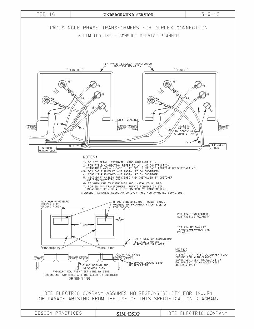
SIM-ESIG
UNDERGROUND SERVICE
TWO SINGLE PHASE TRANSFORMERS FOR DUPLEX CONNECTION
DESIGN PRACTICES
OR DAMAGE ARISING FROM THE USE OF THIS SPECIFICATION DIAGRAM.
CONSULT MATERIAL COORDINATOR D-241 WSC FOR APPROVED SUPPLIERS.
BOX PADS
3. BOX PAD FURNISHED AND INSTALLED BY CUSTOMER.
DUCT
PRIMARY
PRIMARY DUCT
SECOND
ADDITIVE POLARITY
167 KVA OR SMALLER TRANSFORMER
ALTERNATIVE)
EQUIVALENT IS AN ACCEPTABLE
(ANDERSON ELECTRIC GC-103-02
GROUND ROD WITH CLAMP.
A 5/8’’ DIA. X 8’ LG COPPER CLAD
EQUIPMENT.
OPENING ON PRIMARY/SWITCH SIDE OF
BRING GROUND LEADS THROUGH CABLE
NOTE:
POLARIY
TRANSFORMER-ADDITIVE
167 KVA OR SMALLER
SUBTRACTIVE POLARITY
250 KVA TRANSFORMER
GROUNDING
GROUNDING FURNISHED AND INSTALLED BY CUSTOMER
IF REQUESTED
TELEPHONE GROUND LEAD
TO GROUND RING
CLAMP GROUND ROD
PADMOUNT EQUIPMENT SET SIDE BY SIDE
FINAL GRADE
6 REQUIRED SEE NOTE
(ED. NO. 240-0087)
1/2’’ DIA. 8’ GROUND ROD
TRANSFORMERS
1’
4’ MAX
GROUND RING
COPPER WIRE
MINIMUM #1/0 BARE
TO ASSURE OPENING WILL BE COVERED BY TRANSFORMER.
7. FOR 25 KVA TRANSFORMERS, ROTATE FOUNDATION 90°
5. SECONDARY CABLES FURNISHED AND INSTALLED BY CUSTOMER
4. CONDUIT FURNISHED AND INSTALLED BY CUSTOMER.
STANDARDS MANUAL, PAGE 1-17-225. (INDICATE ADDITIVE OR SUBTRACTIVE)
2. FOR FIELD CONNECTION REFER TO UG LINE CONSTRUCTION
1. DO NOT DETAIL ESTIMATE (HAND ORDER-PR 21).
0 2
P
0 1
N
GROUND STRAP
BY REMOVING
NEUTRAL
ISOLATE
1’ MIN.
* LIMITED USE - CONSULT SERVICE PLANNER
’’POWER’’
X3
X2
X1
L2
H1B
H1A
X3
X2
X1
L2
H1B
H1A
L1
’’LIGHTER’’
NOTES:
3-6-12FEB 16
DTE ELECTRIC COMPANY ASSUMES NO RESPONSIBILITY FOR INJURY
DTE ELECTRIC COMPANY
6. PRIMARY CABLES FURNISHED AND INSTALLED BY DTE.
AND TERMINATED BY DTE.
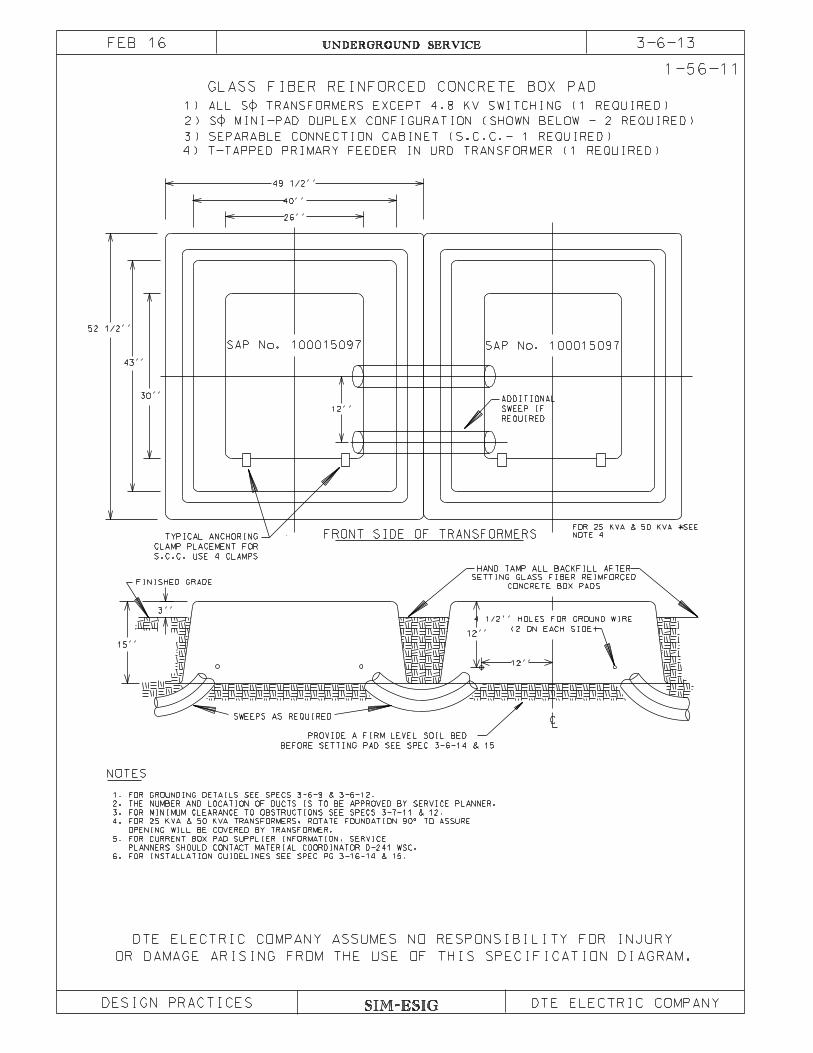
SIM-ESIG
3-6-13UNDERGROUND SERVICE
GLASS FIBER REINFORCED CONCRETE BOX PAD
OR DAMAGE ARISING FROM THE USE OF THIS SPECIFICATION DIAGRAM.
1-56-11
BEFORE SETTING PAD SEE SPEC 3-6-14 & 15
PROVIDE A FIRM LEVEL SOIL BED
(2 ON EACH SIDE)
4 1/2’’ HOLES FOR GROUND WIRE
12’’
12’’
SWEEPS AS REQUIRED
3’’
15’’
12’’
52 1/2’’
43’’
30’’
49 1/2’’
40’’
26’’
2) S MINI-PAD DUPLEX CONFIGURATION (SHOWN BELOW - 2 REQUIRED)
REQUIRED
SWEEP IF
ADDITIONAL
S.C.C. USE 4 CLAMPS
CLAMP PLACEMENT FOR
TYPICAL ANCHORING FRONT SIDE OF TRANSFORMERS
FINISHED GRADE
NOTES
4) T-TAPPED PRIMARY FEEDER IN URD TRANSFORMER (1 REQUIRED)
3) SEPARABLE CONNECTION CABINET (S.C.C.- 1 REQUIRED)
1) ALL S TRANSFORMERS EXCEPT 4.8 KV SWITCHING (1 REQUIRED)
HAND TAMP ALL BACKFILL AFTER
SETTING GLASS FIBER REIMFORCED
CONCRETE BOX PADS
1. FOR GROUNDING DETAILS SEE SPECS 3-6-9 & 3-6-12.
2. THE NUMBER AND LOCATION OF DUCTS IS TO BE APPROVED BY SERVICE PLANNER.
3. FOR MINIMUM CLEARANCE TO OBSTRUCTIONS SEE SPECS 3-7-11 & 12.
4. FOR 25 KVA & 50 KVA TRANSFORMERS, ROTATE FOUNDATION 90° TO ASSURE
OPENING WILL BE COVERED BY TRANSFORMER.
5. FOR CURRENT BOX PAD SUPPLIER INFORMATION, SERVICE
PLANNERS SHOULD CONTACT MATERIAL COORDINATOR D-241 WSC.
6. FOR INSTALLATION GUIDELINES SEE SPEC PG 3-16-14 & 15.
NOTE 4
FOR 25 KVA & 50 KVA SEE
FEB 16
DESIGN PRACTICES
DTE ELECTRIC COMPANY ASSUMES NO RESPONSIBILITY FOR INJURY
DTE ELECTRIC COMPANY
SAP No. 100015097 SAP No. 100015097
UNDERGROUND SERVICE 3-6-14FEB 16
BOX PAD INSTALLATION GUIDELINES
These guidelines are intended to be general and applicable to all underground line equipmentfoundation construction.
1. Excavation Requirements.
Excavation shall be to a depth that will permit preparation of the foundation as specifiedand installation of the box pad at prescribed depth. The length and width of the excavatedhole shall be sufficient to permit the installation of the pad and the compaction of the soilfor load bearing.
The excavations shall be to a minimum width equal to the outside bottom flangedimensions plus six inches. Excavation widths shall allow for at least 3" of clearance oneach side of the box pad bottom flange. This will result in a clearance of approximately 6"on either side of the box pad sidewalls.
2. Bedding Requirements.
The box pad shall be laid on sound soil, cut true and even, so that the bottom flange of thepad will have bearing on at least 80 percent of its width and all of its length. Whenconditions such as unstable soil, frozen backfill or rock are encountered, special actionmust be taken to provide a sound soil base for the entire foundation.
For localized poor conditions, the necessary load bearing capacity shall be achieved byremoving the unsuitable material and replacing it with well-compacted crush rock or othergranular material. This material must pass a 3/8" sieve with a maximum of 5 percentpassing a number 10 sieve.
3. Backfilling Operations.
All box pad excavations shall be backfilled with suitable material and compacted to thespecified final grade. Suitable material shall be defined as mineral soil reasonably free offoreign materials, rubbish, debris, etc.
Bedding shall be free of frozen clumps, oversized stone, rock or concrete, bituminouschunks or other unsuitable materials that may damage the box pad. Compaction of backfillmaterials can be accomplished with power or hand equipment methods.
Do not fill box pad cavity after pad placement. The internal cavity must be clear to providespace for cable operating slack.
SIM-ESIG SIM-ESIG: 3-6
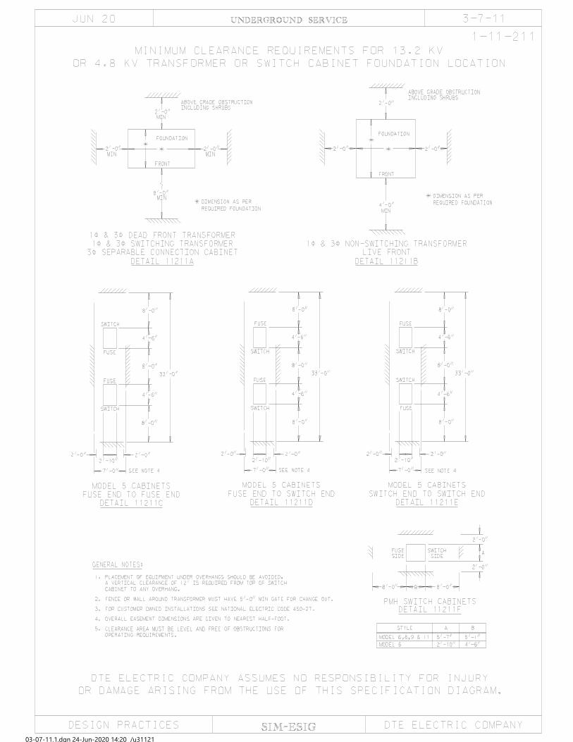
03-07-11.1.dgn 24-Jun-2020 14:20 /u31121

4'-0"
FOUNDATION
FRONT
MIN
MIN
MINMIN
8'-0"
NO
NO
NOTES:
OPERATING REQUIREMENTS.
CLEARANCE AREA MUST BE LEVEL AND FREE OF OBSTRUCTIONS FOR3.
FOR CUSTOMER OWNED INSTALLATIONS SEE NATIONAL ELECTRIC CODE 450-27.2.
CABINET TO ANY OVERHANG.
A VERTICAL CLEARANCE OF 12' IS REQUIRED FROM TOP OF SWITCH
PLACEMENT OF EQUIPMENT UNDER OVERHANGS SHOULD BE AVOIDED.1.
2'-0"
FOUNDATION
FRONT
MIN
MIN
MIN
8'-0"
NO
DETAIL 11211G
FEEDER SECTION SWITCH
2-WAY 3}
DETAIL 11211H
FEEDER SECTION SWITCH
3-WAY 3}
2'-0"
MIN
ON 1-56-124 OR 1-56-125
*DIMENSIONS AS PER FOUNDATION
FOUNDATION ON 1-56-123
*DIMENSIONS AS PER
3-7-11.1UNDERGROUND SERVICE
FOR TRANSFORMER WITH MSTC FOUNDATION LOCATION
MINIMUM CLEARANCE REQUIREMENTS
1-11-211.1
JUN 20
SIM-ESIGDESIGN PRACTICES
OR DAMAGE ARISING FROM THE USE OF THIS SPECIFICATION DIAGRAM.
DTE ELECTRIC COMPANY ASSUMES NO RESPONSIBILITY FOR INJURY
DTE ELECTRIC COMPANY
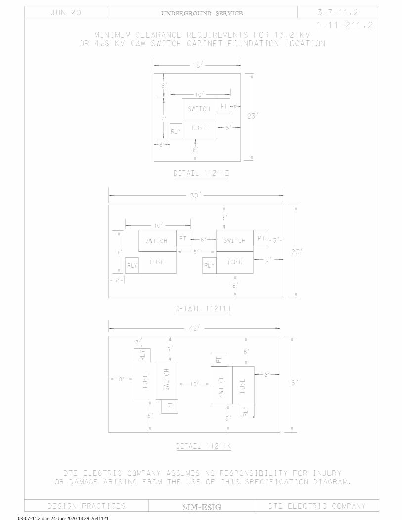
03-07-11.2.dgn 24-Jun-2020 14:29 /u31121
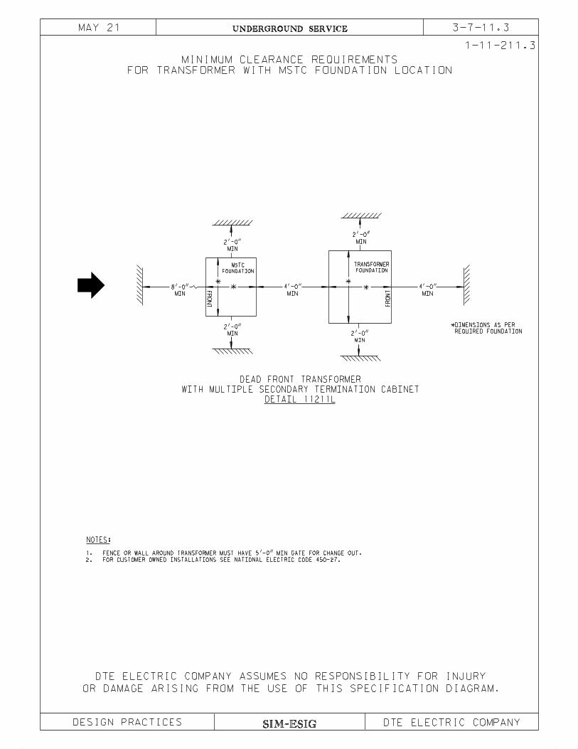
SIM-ESIG
3-7-11.3UNDERGROUND SERVICE
FOR TRANSFORMER WITH MSTC FOUNDATION LOCATION
MINIMUM CLEARANCE REQUIREMENTS
DESIGN PRACTICES
OR DAMAGE ARISING FROM THE USE OF THIS SPECIFICATION DIAGRAM.
MAY 21
DTE ELECTRIC COMPANY ASSUMES NO RESPONSIBILITY FOR INJURY
DTE ELECTRIC COMPANY
MIN
2'-0"
MIN
4'-0"
DETAIL 11211L
WITH MULTIPLE SECONDARY TERMINATION CABINET
DEAD FRONT TRANSFORMER
MIN
2'-0"
MIN
2'-0"
MIN
2'-0"
MIN
4'-0"
NOTES:
FOR CUSTOMER OWNED INSTALLATIONS SEE NATIONAL ELECTRIC CODE 450-27.2.
FENCE OR WALL AROUND TRANSFORMER MUST HAVE 5'-0" MIN GATE FOR CHANGE OUT.1.
MIN
8'-0"
FOUNDATION
TRANSFORMER
FR
ON
T
FOUNDATION
MSTC
FR
ON
T
REQUIRED FOUNDATION
*DIMENSIONS AS PER
1-11-211.3
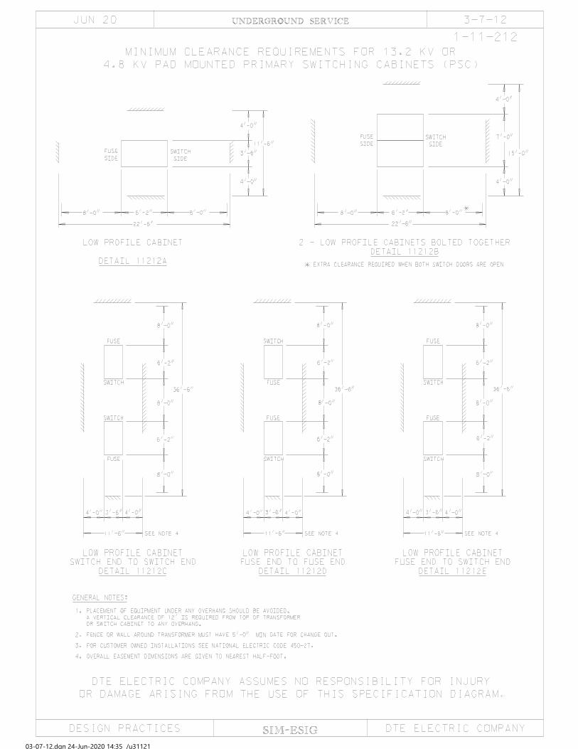
03-07-12.dgn 24-Jun-2020 14:35 /u31121

SIM-ESIG
3-7-14UNDERGROUND SERVICE
UNDERGROUND CLEARANCES FROM SWIMMING POOLS
DESIGN PRACTICES
OR DAMAGE ARISING FROM THE USE OF THIS SPECIFICATION DIAGRAM.
JUL 20
THE DTE ELECTRIC COMPANY ASSUMES NO RESPONSIBILITY FOR INJURY
DTE ELECTRIC COMPANY
1-11-214
NOTE 3
NOTE 15' MIN
CONDUCTOR(S)
SUPPLY
UNDERGROUND
24" MIN
3-4-1.
UNDERGROUND SUPPLY CONDUCTORS SHALL HAVE A MINIMUM COVER OF 24 INCHES. SEE PAGE
NOTES:
UNDERGROUND WIRING SHALL NEVER BE PERMITTED UNDER POOLS.1.
2.
3.
351(C)(1).
AND THE INSIDE WALL OF THE POOL IN COMPLIANCE WITH NEC ARTICLE 680.10 AND NESC
A MINIMIUM DISTANCE OF 5 FT. SHALL EXIST BETWEEN ANY UNDERGROUND SUPPLY CONDUCTOR(S)
4.
INTERMEDIATE METAL CONDUIT, OR A NONMETALIC SCH 40 PVC.
FROM THE POOL, SUCH WIRING SHALL BE PERMITTED WHERE INSTALLED IN RIGID METAL CONDUIT,
WHERE SPACE LIMITATIONS PREVENT WIRING FROM BEING ROUTED A DISTANCE OF 5 FT. OR MORE
5.FOR OVERHEAD CLEARANCES AROUND POOLS REFER TO 4-4-5.1
UNDERGROUND SERVICE 3-12-1
OCT 17
PRECONSTRUCTION METER MOUNT
1. General. As an accommodation to the builder or developer, DTE Electric will allow an underground service to
be installed to a preconstruction meter mount fastened to the foundation or basement wall before construction of the building framework. The preconstruction meter mount (PCM) will be the permanent support for the meter on the completed building and should satisfy the following conditions:
(a) Installation safety. (b) Standard service requirements. (c) Ease of service installation and maintenance. (d) Protection of service conductors and proper operation of metering equipment during and after
building construction. The electrical contractor responsible for the PCM installation must review the plans with the DTE
Electric Planner before installation begins. The contractor must also comply with the requirements of state or municipal inspectors. DTE Electric offers the following specifications as a guide for PCM installations:
2. Manufactured or Fabricated PCM Assemblies. (a) Accepted by System Equipment and Engineering. DTE Electric OH & UG Construction
Standards must accept manufactured or fabricated PCM assemblies before installation in the DTE Electric service area. (See page 3-12-3 for acceptable units.)
(b) Specifications. Distributors, representatives, or fabricators are required to supply
specifications and make a unit available for inspection by the OH & UG Construction Standards Group.
(c) UL Listed. Power outlet cabinets must have UL labels and have a weatherproof rating
(NEMA 3R). Outlets must be GFCI protected. 3. Meter Enclosures. DTE Electric allows the 1 Φ CL 200, 1 Φ CL 320, or 1 Φ CL 200 2 position horizontal meter
enclosure to be mounted to the PCM. No other meter enclosures or arrangement for connecting the meter will be accepted. Customers are responsible for obtaining and installing enclosures. For a list of approved enclosure vendors refer to Section 5-8.
NOTE: Any bond between the meter enclosure and joint users that interferes with removing the cover
on the meter box is a violation of NEC 250.94 (3). The joint user who created the violation must correct the situation.
4. PCM Location. (a) Properly supported. The PCM must be located so that a completed wall will support the
back of the meter enclosure. SIM-ESIG SIM-ESIG: 3-12
UNDERGROUND SERVICE 3-12-2
JUL 18 (b) Acceptable location. The PCM location must be selected and marked with care so
that it will not interfere with other tradespersons in the performance of their work. Also, the PCM must not conflict with windows, doors, ledges, dormers, feature details, patios, etc.
(c) Moving a PCM. In the event that it is necessary to move a PCM after the service has
been installed, the customer’s contractor must relocate the PCM and a DTE Electric crew must relocate the service conductors. Since moving the PCM will require de-energizing the service lateral, the work of the customer’s contractor and the DTE Electric crew must be coordinated.
(d) Relocation charges. The customer will be billed for any work done by DTE Electric
to relocate or de-energize the service lateral. In some cases, it may be easier and less expensive to install another PCM at the new location and have the service rerouted to it. The old PCM can then be removed and reused at another job site.
5. PCM Installation. (a) By Contractor. The customer’s contractor installs the PCM. DTE Electric crews
will not install or make any corrections to an improperly installed PCM. The installation must be done in a workmanlike manner so that the PCM is solid and plumb.
(b) Compatible with Building. The PCM must be designed so that it will not have to be
moved or modified in any way to complete construction of the wall behind it. The customer must be certain that tradespersons working on the building will not have problems. The various types of wall construction must be taken into consideration.
6. Materials.
All support parts for the manufacture of a PCM must be made of solid channel steel (no uni-strut members) and have surface protection that will ensure a long life, particularly those portions in direct contact with the earth where the most severe corrosion can be expected. The thickness of the metal must be such that adequate support and resistance to corrosion will be assured.
7. Mounting of Other Equipment. DTE Electric Planning must accept any equipment that is to be fastened to the PCM
assembly temporarily or permanently. Equipment other than DTE Electric devices will not be mounted on the meter enclosure nor depend upon the meter enclosure for support. In particular, any power outlet cabinet intended for use during construction cannot be supported by only a nipple or raceway.
UNDERGROUND SERVICE 3-12-3
JUL 18
8. Temporary Construction Service.
A temporary service power outlet cabinet can be mounted on the PCM assembly providing that it does not depend on the meter enclosure for support. The person or company
installing such temporary service must obtain permission from DTE Electric to break the
meter enclosure seal and make connections. If the electric account is closed or the meter is
in the disconnect position, application must be made to DTE Electric to install or turn on
the electric meter. The temporary service must be installed in accordance with applicable ordinances and regulations of the governmental inspection authority having jurisdiction and the National Electrical Code.
9. Grade.
Before calling for service installation, grade on the building site must be established to within 4 inches of final grade. The service route must be clear of building materials, debris, and other obstructions.
10. Inspected by DTE Electric Planning.
The following manufactured or fabricated PCM assemblies have been examined by DTE Electric Planning and are acceptable to DTE Electric as submitted. The purpose of this inspection is to protect DTE Electric’s interests. There is no intention on the part of DTE Electric to assume any purchaser’s responsibility for the decision to use a particular PCM or to police the quality of the delivered unit. The person buying the PCM must examine the assembly to be sure that the manufacture has followed the material and dimension specifications contained in this section. Any party that decides to construct their own PCM assembly should submit a drawing to DTE Electric at [email protected] for approval before installation to avoid a rejection of the installation.
11. Acceptable Preconstruction Meter Mounts.
DTE Electric Planner will approve the installation of PCM based on typical installation specifications (see 3-12-4). If builder needs to purchase a PCM, the following preconstruction meter mounts have been accepted for use in the DTE Electric Service Area. Manufacturers desiring to have their equipment listed may contact DTE Electric at [email protected]
(a) Your Electrical Solutions (b) Corby Energy Services [email protected] 6001 Schooner Drive www.yourelectricalsolutions.net Belleville, MI 48111 Toll Free 855.644.2400 734.547.9237 [email protected] (c) B&B Electrical www.bbelec.com 2804 Orchard Lake Road #203 Keego Harbor, MI 48320 248.391.0207

NOTES:
UNDERGROUND SERVICE
1. SEE OTHER PAGES IN THIS SECTION ON UNDERGROUND SERVICE INSTALLATION.
2. MUST COMPLY WITH THE NATIONAL ELECTRICAL CODE AND LOCAL RULES.
GRADE MUST PROVIDE FIRM SUPPORT BEFORE, DURING AND AFTER
CONSTRUCTION.
3. METER MOUNT CONSTRUCTION AND FASTENING ABOVE AND/OR BELOW
TYPICAL INSTALLATION
PRECONSTRUCTION METER MOUNT (PCM)
BRICK LEDGE
20 AMP GFCIOUTLET & BREAKER
2’’ PIPE CLAMP
TOP OF BASEMENTANCHOR PLATE
DISCONNECT SUPPORT BRACKET
MAIN UPRIGHTSUPPORT BRACKET
TOP OFBASEMENT WALL
2’’ X 5’ PVC
200 AMPMETER BOX
BOTTOM SUPPORT
BRICK BRACKETBRICK
BRACKET
MAIN SUPPORTUPRIGHT
TOP OF BASEMENTANCHOR PLATE
ANCHORPINS
METER BOXSUPPORT PLATE
ANCHOR PLATE
RISER
4. USE PLASTIC BUSHING OR INSULATED THROAT BUSHING. BOND PER N.E.C.
ARTICLE 250. PVC CONDUIT WITH REAMED AND ROUNDED EDGES DOES NOT
REQUIRE BOTTOM BUSHING.
5/8" X 8’ GROUND ROD
3-12-4
DESIGN PRACTICES DTE ELECTRIC COMPANYSIM-ESIG
OCT 17
SEE NOTE 8
DTE ELECTRIC COMPANY ASSUMES NO RESPONSIBILITY FOR INJURY
OR DAMAGE ARISING FROM THE USE OF THIS SPECIFICATION DIAGRAM.
8.
1-9-225
SEE NOTE 4
NON-METALLIC BUSHING
EXCAVATION
BEYOND
MIN. 24"
EXTEND SWEEP
GRADE
FINALGRADE
FINAL
NOTE 5
SEE
COVER
24" MINIMUM
6. FINAL GRADE MUST BE WITHIN 4" OF THE 24" MINIMUM COVER.
5. BUILDER/ELECTRICIAN MUST MARK THE "BLIND SIDE" OF THE SWEEP.
INSTALLED BY CONTRACTOR
METER ELCLOSURE FURNISHED AND
UNCOMPACTED SOIL
LOOSE
CHART ON 3-4-1
SEE CONDUIT
CONDUIT INTERMEDIATE METAL CONDUIT (IMC) NEMA TC-2 SCHEDULE 40 PVC.
7. USE 2" FOR 3/0 DTE SERVICE (CONSULT PLANNER) RIGID GALVANIZED STEEL
THE JOINT USER WHO CREATED THE VIOLATION MUST CORRECT THE SITUATION.
WITH REMOVING THE COVER ON THE METER BOX IS A VIOLATION OF NEC 250.94 (3).
ANY BOND BETWEEN THE METER ENCLOSURE AND JOINT USERS THAT INTERFERES

SIM-ESIG
3-13-11UNDERGROUND SERVICE
CATV POWER SUPPLY INSTALLATION
DESIGN PRACTICES
OR DAMAGE ARISING FROM THE USE OF THIS SPECIFICATION DIAGRAM.
A. SERVICE CABLE
NOTES:
CABLES. HAND DIG CLOSE TO TRANSFORMER, PEDESTAL, OR DISTRIBUTION CABLES. IDENTIFY IF
OR PEDESTAL.
3. CUSTOMER UNDERGROUND CABLE.
PAGE 1-43-72 IN THE UNDERGROUND LINE CONSTRUCTION STANDARDS MANUAL.
B. CLEARANCES
PEDESTAL: SIMILAR TO DETAIL 23227F
TRANSFORMER: SIMILAR TO DETAIL 23227E
METHOD OF INSTALLATION:
CONTRACTOR WILL FURNISH AND INSTALL CABLE UP TO BUT NOT IN OR UNDER
RESPONSIBILITIES:
ALUMINUM SINGLE CONDUCTOR TYPE U.S.E. AND CROSS LINKED POLYETHYLENE RHH-RHW.
SPECIFICATIONS:
4. CATV POWER SUPPLY.
BY CONTRACTOR
FURNISHED AND INSTALLED
NEC APPROVED GROUND
LEGEND:
GRADE LEVEL
(NOTE B)
24’’
4’’ MAX
(NOTE A)
OR
41
3
3
2
1-9-236
FEB 16
STRIPPING 4’’ OF INSULATION AT END. ALLOW SUFFICIENT CABLE FOR CONNECTION BY DTE
CABLES OR DIRECTLY IN FRONT OF TRANSFORMER DOOR, NOR WITHIN 2’ OF ANY EXISTING DTE
1. DTE ELECTRIC PADMOUNT TRANSFORMER.
2. DTE ELECTRIC SECONDARY PEDESTAL. (NOT AVAILABLE FOR FRONT LOT U.R.D.)
CONTRACTOR WILL CONTACT MISS DIG WHEN WORKING IN PROXIMITY OF DTE ELECTRIC DISTRIBUTION
DTE ELECTRIC DETAIL FOR INSTALLATION AND TERMINATION:
CATV POWER SUPPLY IS NOT TO BE INSTALLED DIRECTLY OVER DTE ELECTRIC DISTRIBUTION
DTE ELECTRIC COMPANY ASSUMES NO RESPONSIBILITY FOR INJURY
DTE ELECTRIC COMPANY
SERVICE CONNECTIONS WILL BE MADE TO TRANSFORMER ONLY WHEN NO PEDESTAL EXISTS
NOTE:
TRANSFORMER OR PEDESTAL. DTE ELECTRIC WILL INSTALL AND TERMINATE SERVICE IN TRANSFORMER
ELECTRIC: 8’ AT TRANSFORMER, 4’ AT PEDESTAL. SEAL CABLE END AGAINST MOISTURE.
ELECTRIC FACILITY. IF INSTALLED AT SAME TIME AS DTE ELECTRIC FACILITIES REFER TO
UNDERGROUND SERVICE 3-14-17 FEB 16 MOBILE HOME SERVICE 1. General.
The mobile home park owner is responsible for the selection, purchase, installation, and maintenance of the mobile home pedestal. All installations must meet the following conditions to be installed in the DTE Electric service area:
(a) Installation safety.
(b) Sufficient load capability.
(c) Reasonable life expectancy.
(d) Ease of maintenance.
The electrical contractor responsible for the pedestal installation must review the plans with the DTE Electric Planner before beginning construction. The contractor must also comply with the requirements of the municipal inspection authority. DTE Electric offers the following specifications as a guide to mobile home pedestal installations.
2. Load Capability.
The standard DTE Electric 3/0 AWG aluminum underground service lateral will adequately feed a 200-ampere service. The National Electrical Code and the Mobile Home Manufacturers Association Standard for Mobile Home Parks both set a minimum standard of 100 amperes for mobile home service equipment. Accordingly, mobile home pedestals must have the capability of supplying 100 amperes, and should be constructed so that the main disconnect can be replaced with one of up to 200 amperes capacity without modification to the pedestal. A number of manufacturers offer units with plug-in interchangeable devices to fit a wide variety of loads.
3. Pedestals and Disconnect Cabinets.
(a) Accepted by DTE Electric Planner. DTE Electric Planner must accept manufactured or fabricated pedestal assemblies (See page 3-14-19 for acceptable units) before installation in the DTE Electric service area.
(b) Specifications. Distributors, representatives or fabricators are required to supply specifications and make a unit available for inspection by OH & UG Construction Standards Group.
(c) UL Listed. Pedestal mains or power outlet cabinets must have UL labels and be listed as suitable for use as service equipment. They must comply with the load requirements in paragraph 2 above and have a weatherproof rating (NEMA 3R).
(d) Interrupting Rating. The short circuit current interrupting rating for the overcurrent device(s) must be a minimum of 10,000 amperes to equal the expected maximum available fault current.
SIM-ESIG SIM-ESIG: 3-14
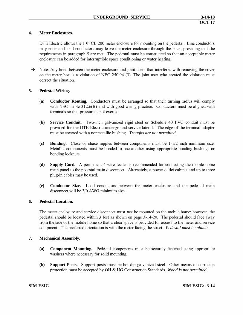
UNDERGROUND SERVICE 3-14-18
OCT 17
4. Meter Enclosures.
DTE Electric allows the 1 Φ CL 200 meter enclosure for mounting on the pedestal. Line conductors
may enter and load conductors may leave the meter enclosure through the back, providing that the requirements in paragraph 5 are met. The pedestal must be constructed so that an acceptable meter enclosure can be added for interruptible space conditioning or water heating.
Note: Any bond between the meter enclosure and joint users that interferes with removing the cover
on the meter box is a violation of NEC 250.94 (3). The joint user who created the violation must correct the situation.
5. Pedestal Wiring.
(a) Conductor Routing. Conductors must be arranged so that their turning radius will comply
with NEC Table 312.6(B) and with good wiring practice. Conductors must be aligned with terminals so that pressure is not exerted.
(b) Service Conduit. Two-inch galvanized rigid steel or Schedule 40 PVC conduit must be
provided for the DTE Electric underground service lateral. The edge of the terminal adapter must be covered with a nonmetallic bushing. Troughs are not permitted.
(c) Bonding. Close or chase nipples between components must be 1-1/2 inch minimum size.
Metallic components must be bonded to one another using appropriate bonding bushings or bonding locknuts.
(d) Supply Cord. A permanent 4-wire feeder is recommended for connecting the mobile home
main panel to the pedestal main disconnect. Alternately, a power outlet cabinet and up to three plug-in cables may be used.
(e) Conductor Size. Load conductors between the meter enclosure and the pedestal main
disconnect will be 3/0 AWG minimum size. 6. Pedestal Location.
The meter enclosure and service disconnect must not be mounted on the mobile home; however, the
pedestal should be located within 3 feet as shown on page 3-14-20. The pedestal should face away from the side of the mobile home so that a clear space is provided for access to the meter and service equipment. The preferred orientation is with the meter facing the street. Pedestal must be plumb.
7. Mechanical Assembly.
(a) Component Mounting. Pedestal components must be securely fastened using appropriate
washers where necessary for solid mounting. (b) Support Posts. Support posts must be hot dip galvanized steel. Other means of corrosion
protection must be accepted by OH & UG Construction Standards. Wood is not permitted. SIM-ESIG SIM-ESIG: 3-14

UNDERGROUND SERVICE 3-14-19
FEB 2018
(c) Mounting Bolts. Meter enclosure mounting bolts must be long enough so that an
extension can be added for interruptible space conditioning or water heating. An extra nut should be provided on each bolt as shown on page 3-14-20.
(d) Approved Posts. The following support posts will provide a reasonably long life in
most soil conditions. Other posts may be used, but must be accepted by OH & UG Construction Standards Group.
(1) Rigid steel conduit (2 in)
Hot dip galvanized (Intermediate metal conduit or fence post is not acceptable.)
(2) Square seamless post (1-3/4 in) 12-gage min. Hot dip galvanized (Unistrut Corp. TELESPAR® Part No. 16F12 or equivalent) 8. Grounding.
A ground rod shall be driven at each pedestal location. Material and installation must comply with NEC Article 250.
9. Mounting of Other Equipment.
Other utility equipment that is mounted on the pedestal must not interfere with the use of the electrical equipment. (See page 3-14-21) Fastening hardware must not present a hazard to any conductors.
10. Acceptable Pedestals.
DTE Electric Planner will approve the installation of pedestals based on typical installation specifications (see 3-4-6 & 3-4-6.1, and 3-14-20 to 3-14-25). If builder needs to purchase a pedestal, the following pedestals have been accepted for use in the DTE Electric service area. Manufacturers desiring to have their equipment listed may contact DTE Electric at [email protected]
(a) Adnic Products Co. (c) Midwest Electric (e) Rollman Electric Co. G6261 N. Saginaw Rd. P.O. Box 910 3351 Consear
Mt. Morris, MI 48458 Hwy. 22 North Lambertville, MI 48144 810.785.2851 Mankato, MN 56002-0910 734.856.1900 506.345.2505
(b) B & B Electrical (f) Nordic Fiberglass, Inc.
Manufacturing (d) Power Plus Industries, Inc. 21415 U.S. Hwy 75 NW 2737 Browning Dr. 16537 Fairway P.O. Box 27 Lake Orion, MI 48360 Livonia, MI 48154 Warren, MN 56762 248.391.3800 734.464.6273 218.745.5095 SIM-ESIG SIM-ESIG: 3-14

SIM-ESIG
3-14-20UNDERGROUND SERVICE
DESIGN PRACTICES
OR DAMAGE ARISING FROM THE USE OF THIS SPECIFICATION DIAGRAM.
METER BOX)
TOP OF
FINISHED
METER AND SERVICE EQUIPMENT.
WORKING CLEARANCE IN FRONT OF
MUST MAINTAIN MIN. 3 FOOT SQUARE
SEE DETAILED SPECIFICATIONS ON PAGE 3-14-17.
FOR WATER HEATER INSTALLATION, SEE PAGES 7-27-1 THROUGH 7-27-4.
SERVICE EQUIPMENT SHALL BE RATED AT NOT LESS THAN 100 AMPS.
GROUNDING MUST COMPLY WITH NEC ARTICLE 250.
MUST COMPLY WITH NEC ARTICLE 550.
MOBILE HOME SERVICE AND FEEDER (PERMANENT WIRING OR SUPPLY CORD)
5.
4.
3.
2.
1.
SERVICE
NOTES:
CONTRACTOR
MIN.
24’’
AC-10
ISC DISCONNECT RESIDENTIAL SERVICE
ISC METER
RESIDENTIAL METER
RCU
INTERRUPTIBLE SPACE CONDITIONING
(6’ MAX. TO
42’’ MIN.
60’’
18’’
SEE NEC 550
SUPPLY CORD
WIRING OR
PERMANENT
MOBILE HOME
ROD
GROUND
LOCATION
PEDESTAL
PREFERRED
HOME
MOBILE
LENGTH
1/3GRADE
CONDUIT
2’’ PVC
RIGID CONDUIT
2’’ GALVANIZED
STRAPS
PIPE
WIRE
GROUND
CAP
MOBILE HOME PEDESTAL
SERVED UNDERGROUND
DISCONNECT
OCT 17
WEATHERPROOF
SERVICE
DISCONNECT
DTE ELECTRIC COMPANY ASSUMES NO RESPONSIBILITY FOR INJURY
DTE ELECTRIC COMPANY
FURNISHED
AND INSTALLED BY
SEE NOTE 6
6.
DISCONNECT
SERVICE
WEATHERPROOF
THE VIOLATION MUST CORRECT THE SITUATION.
VIOLATION OF NEC 250.94 (3). THE JOINT USER WHO CREATED
INTERFERES WITH REMOVING THE COVER ON THE METER BOX IS A
ANY BOND BETWEEN THE METER ENCLOSURE AND JOINT USERS THAT

SIM-ESIG
3-14-21UNDERGROUND SERVICE
DESIGN PRACTICES
OR DAMAGE ARISING FROM THE USE OF THIS SPECIFICATION DIAGRAM.
SERVICE CABLE
TELEPHONE
INTERFACE BOX
20’’ MIN.
TELEPHONE
CONCRETE
SEE NOTE 2.
2’0’’
3’0’’
8’’ MIN.
2’0’’
THIS POST INSTALLATION METHOD IS TO BE USED ONLY WHEN THE MOBILE HOME PARK IS JOINT USE.
SEE PAGES 3-14-17 THRU 20 FOR ELECTRICAL PEDESTAL INSTRUCTIONS AND SPECIFICATIONS.
CONCRETE. WARNING - IF CONCRETE IS ABOVE THE LEVEL SHOWN, FROST HEAVE IS LIKELY TO OCCUR.
GAS COMPANY PERSONNEL WILL INSPECT AND BE RESPONSIBLE FOR THE PROPER TREATMENT OF THE
4.
3.
2.
1.
NOTES:
3’0’’
18’’
BRACKET
GAS METER
JOINT USE MOBILE HOME PEDESTAL INSTALLATION
REFER TO THE GAS COMPANY FOR GAS METER INSTALLATION INSTRUCTIONS.
WEATHERPROOF
DTE ELECTRIC COMPANY ASSUMES NO RESPONSIBILITY FOR INJURY
DTE ELECTRIC COMPANY
SEE NOTE 5
ANY BOND BETWEEN THE METER ENCLOSURE AND JOINT USERS THAT INTERFERES WITH
REMOVING THE COVER ON THE METER BOX IS A VIOLATION OF NEC 250.94 (3). THE JOINT USER WHO
CREATED THE VIOLATION MUST CORRECT THE SITUATION.
5.
OCT 17
DISCONNECT
SERVICE

SIM-ESIG
UNDERGROUND SERVICE
OR DAMAGE ARISING FROM THE USE OF THIS SPECIFICATION DIAGRAM.
METER BOX)
TOP OF
FINISHED
METER AND SERVICE EQUIPMENT.
WORKING CLEARANCE IN FRONT OF
MUST MAINTAIN MIN. 3 FOOT SQUARE*
SERVICE
NOTES:
CONTRACTOR
MIN.
24’’
(6’ MAX. TO
42’’ MIN.
60’’
18’’
SEE NEC 550
WIRING
PERMANENT
STREET LIGHTING
RODGROUNDGRADE
CONDUIT
2’’ PVC
RIGID CONDUIT
2’’ GALVANIZED
STRAPS
PIPE
WIRE
GROUND
CAP
DISCONNECT
SERVICE
WEATHERPROOF
DISCONNECT
SERVICE
WEATHERPROOF
3-14-22
METER BOX FURNISHED
AND INSTALLED BY
5-3-18 & 19
5-3-5
REFERENCE PAGE
NOTE:
DESIGN PRACTICES
DTE ELECTRIC COMPANY ASSUMES NO RESPONSIBILITY FOR INJURY
DTE ELECTRIC COMPANY
SEE NOTE 2
OR ANY LOCATION THAT REQUIRES A REMOTE METER
POST MOUNTED UNDERGROUND SERVICE, 100 TO 200 AMPSINGLE PHASE OR THREE PHASE, USED FOR MOBILE HOME COMMUNITY
OCT 17
SEE NOTE 9
THE JOINT USER WHO CREATED THE VIOLATION MUST CORRECT THE SITUATION.
REMOVING THE COVER ON THE METER BOX IS A VIOLATION OF NEC 250.94 (3).
9. ANY BOND BETWEEN THE METER ENCLOSURE AND JOINT USERS THAT INTERFERES WITH
PERMANENT LETTERS OR STICKERS.
8. ADDRESS MUST BE PERMANENTLY MARKED ON METER ENCLOSURE. USE
7. A GROUND ROD MUST BE INSTALLED IN COMPLIANCE WITH N.E.C. 250.
PHASE 3/0 SERVICES.
FOR 3/0 SINGLE PHASE SERVICE AND 3" CONDUIT FOR THREE
6. DTE ELECTRIC INSTALLED UG SERVICES REQUIRE 2" CONDUIT
N.E.C. 250. PVC CONDUIT MUST BE TRIMMED TO REMOVE SHARP EDGES.
5. RIGID AND IMC CONDUIT REQUIRE NONMETALLIC BUSHINGS WITH BONDING PER
FURNISHED AND INSTALLED BY CUSTOMER.
4. SERVICE DISCONNECT MUST BE RAINTIGHT. THE DISCONNECT IS SIZED,
THE POST MUST BE INSTALLED PLUMB AND REMAIN PLUMB AT ALL TIMES.
3. USE ONLY 2" RIGID PIPE POST WITH CAP. WOOD POSTS ARE NOT ALLOWED.
6’ MAXIMUM TO TOP OF METER BOX.
42" MINIMUM HEIGHT TO CENTER OF METER FACE FROM GRADE AND
CL 200 FOR 100 TO 200 AMP THREE PHASE
CL 200 FOR 100 TO 200 AMP SINGLE PHASE
2. METER BOX MAY BE:
IS OWNED AND MAINTAINED BY THE CUSTOMER.
1. ALL POST MOUNTED SERVICE EQUIPMENT, OTHER THAN THE METER BOX
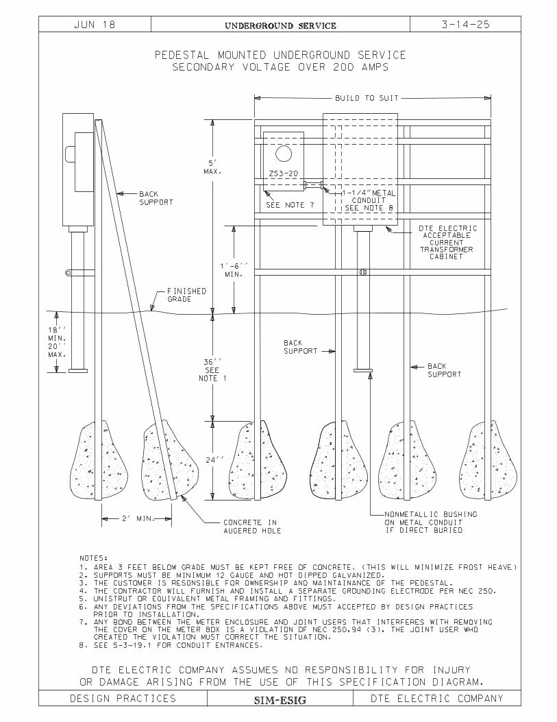
SIM-ESIG
3-14-25UNDERGROUND SERVICE
SECONDARY VOLTAGE OVER 200 AMPS
PEDESTAL MOUNTED UNDERGROUND SERVICE
DESIGN PRACTICES
OR DAMAGE ARISING FROM THE USE OF THIS SPECIFICATION DIAGRAM.
DTE ELECTRIC COMPANY ASSUMES NO RESPONSIBILITY FOR INJURY
DTE ELECTRIC COMPANY
BUILD TO SUIT
BACK
SUPPORT
BACK
SUPPORT
NONMETALLIC BUSHING
ON METAL CONDUITCONCRETE IN
AUGERED HOLE
NOTES:
1. AREA 3 FEET BELOW GRADE MUST BE KEPT FREE OF CONCRETE. (THIS WILL MINIMIZE FROST HEAVE)
2. SUPPORTS MUST BE MINIMUM 12 GAUGE AND HOT DIPPED GALVANIZED.
3. THE CUSTOMER IS RESONSIBLE FOR OWNERSHIP AND MAINTAINANCE OF THE PEDESTAL.
6. ANY DEVIATIONS FROM THE SPECIFICATIONS ABOVE MUST ACCEPTED BY DESIGN PRACTICES
PRIOR TO INSTALLATION.
4. THE CONTRACTOR WILL FURNISH AND INSTALL A SEPARATE GROUNDING ELECTRODE PER NEC 250.
5. UNISTRUT OR EQUIVALENT METAL FRAMING AND FITTINGS.
18’’
MIN.
20’’
MAX.
2’ MIN.
36’’
SEE
NOTE 1
24’’
IF DIRECT BURIED
5’
MAX.
1’-6’’
MIN.
BACK
SUPPORT
FINISHED
GRADE
ZS3-20
CURRENT
METAL
ACCEPTABLE
TRANSFORMER
CABINET
DTE ELECTRIC
CREATED THE VIOLATION MUST CORRECT THE SITUATION.
THE COVER ON THE METER BOX IS A VIOLATION OF NEC 250.94 (3). THE JOINT USER WHO
7. ANY BOND BETWEEN THE METER ENCLOSURE AND JOINT USERS THAT INTERFERES WITH REMOVING
SEE NOTE 7
1-1/4"
SEE NOTE 8
CONDUIT
8. SEE 5-3-19.1 FOR CONDUIT ENTRANCES.
JUN 18

UNDERGROUND SERVICE 3-15-1
OCT 17
TELEPHONE COMPANY POWER PEDESTAL
1. General. The Telephone Company is responsible for the selection, purchase, installation, and maintenance of the
power pedestal. All installations must meet the following conditions to be installed in the DTE Electric service area:
(a) Installation safety. (b) Sufficient load capability. (c) Reasonable life expectancy. (d) Ease of maintenance. The electrical contractor responsible for the pedestal installation must review the plans with the DTE
Electric Planner before beginning construction. The contractor must also comply with the requirements of the municipal inspection authority. DTE Electric offers the following specifications as a guide for power pedestal installations:
2. Load Capability. The pedestal must accept the standard DTE Electric 3/0 AWG aluminum underground service lateral and
be capable of supplying 200 amperes. 3. Pedestals and Disconnects. (a) Accepted by OH & UG Construction Standards. DTE Electric OH & UG Construction
Standards must accept manufactured or fabricated pedestal assemblies before installation in the DTE Electric service area. (See page 3-14-19 for accepted manufacturers.)
(b) Specifications. Distributors, representatives or fabricators are required to supply specifications
and make a unit available for inspection by OH & UG Construction Standards. (c) UL Listed. Pedestal mains and transfer switch cabinets must have UL labels and be listed as
suitable for use as service equipment. They must comply with the load requirements in paragraph 2 above and have a weatherproof rating (NEMA 3R).
(d) Interrupting Rating. The short circuit current interrupting rating for the overcurrent device(s)
must be a minimum of 10,000 amperes to equal the expected maximum available fault current. 4. Meter Enclosures. DTE Electric allows the 1 Φ CL 200 meter enclosure for mounting on the pedestal. Line conductors may
enter and load conductors may leave the meter enclosure through the back, providing the requirements in paragraph 5 are met.
Note: Any bond between the meter enclosure and joint users that interferes with removing the cover on the
meter box is a violation of NEC 250.94 (3). The joint user who created the violation must correct the situation.
SIM-ESIG SIM-ESIG: 3-15

UNDERGROUND SERVICE 3-15-2FEB 16
5. Pedestal Wiring.
(a) Conductor Routing. Conductors must be arranged so that their turning radius willcomply with NEC Article 312 and with good wiring practice. Conductors must bealigned with terminals so that pressure is not exerted.
(b) Service Conduit. Two-inch galvanized rigid steel or Schedule 40 PVC conduit mustbe provided for the DTE Electric underground service lateral. The edge of theterminal adapter must be covered with a nonmetallic bushing. Troughs are notpermitted.
(c) Bonding. Close or chase nipples between components must be 1-1/2 inch minimumsize. Metallic components must be bonded to one another using appropriate bondingbushings or bonding locknuts.
6. Mechanical Assembly.
(a) Component Mounting. Pedestal components shall be securely fastened usingappropriate washers where necessary for solid mounting.
(b) Support Posts. Support posts must be hot dip galvanized steel. Other means ofcorrosion protection must be accepted by DTE Electric Planning. Wood is notpermitted.
(c) Hardware. Fasteners used for assembly of components must have adequatemechanical strength to assure dependable service.
(d) Approved Posts. The following support posts will provide a reasonably long life inmost soil conditions. Other posts may be used, but must be accepted by DTE ElectricPlanning.
(1) Rigid steel conduit (2 in)Hot dip galvanized(Intermediate metal conduit or fence post is not acceptable.)
(2) Square seamless post (1-3/4 in) 12-gage min.Hot dip galvanized(Unistrut Corp. TELESPAR® Part No. 16F12 or equivalent)
7. Grounding.
A ground rod shall be driven at each pedestal location. Material and installation mustcomply with NEC Article 250.
8. Mounting of Other Equipment.
Surge arresters will be connected on the load side of the main overcurrent device and willnot be mounted in the meter enclosure.
SIM-ESIG SIM-ESIG: 3-15
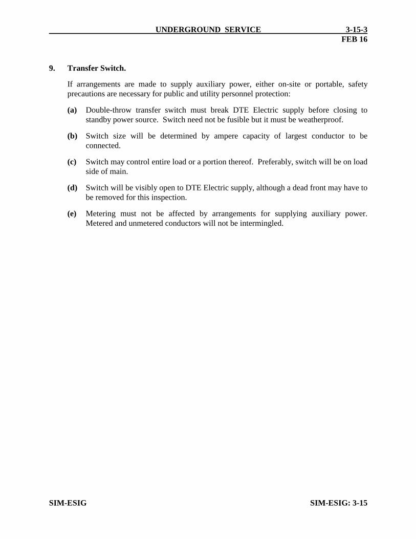
UNDERGROUND SERVICE 3-15-3FEB 16
9. Transfer Switch.
If arrangements are made to supply auxiliary power, either on-site or portable, safetyprecautions are necessary for public and utility personnel protection:
(a) Double-throw transfer switch must break DTE Electric supply before closing tostandby power source. Switch need not be fusible but it must be weatherproof.
(b) Switch size will be determined by ampere capacity of largest conductor to beconnected.
(c) Switch may control entire load or a portion thereof. Preferably, switch will be on loadside of main.
(d) Switch will be visibly open to DTE Electric supply, although a dead front may have tobe removed for this inspection.
(e) Metering must not be affected by arrangements for supplying auxiliary power.Metered and unmetered conductors will not be intermingled.
SIM-ESIG SIM-ESIG: 3-15

SIM-ESIG
UNDERGROUND SECTION
DESIGN PRACTICES
OR DAMAGE ARISING FROM THE USE OF THIS SPECIFICATION DIAGRAM.
#6 COPPER
8’ GROUND ROD
FOR AUXILIARY POWER
TRANSFER SWITCH
NOTES:
CAP
GROUND
WIRE
PIPE
STRAPS
2’’ GALVANIZED
RIGID CONDUIT
2’’ PVC
CONDUIT
GRADE
18’’
60’’
42’’ MIN.
(6’ MAX. TO
24’’
MIN.
CONTRACTOR
FINISHED
TOP OF
METER BOX)
TELEPHONE COMPANY POWER PEDESTAL
FOR PAD MOUNTED CARRIER SYSTEM
3-15-4
AND INSTALLED BY
OCT 17
WEATHERPROOF
DISCONNECT
SERVICE
ENCLOSURE FURNISHED
DTE ELECTRIC COMPANY ASSUMES NO RESPONSIBILITY FOR INJURY
DTE ELECTRIC COMPANY
SEE NOTE 5
COMPANY CONTRACTOR.
2. SERVICE ENTRANCE MAIN SWITCH FURNISHED AND INSTALLED BY TELEPHONE
COMPANY CONTRACTOR.
1. DTE APPROVED METER ENCLOSURE FURNISHED AND NSTALLED BY TELEPHONE
3. SUPPORT CONDUIT FURNISHED AND INSTALLED BY TELEPHONE COMPANY CONTRACTOR.
4. SEE DETAILED NOTES ON SIM-ESIG PAGE 3-15-1 THROUGH 3-15-3.
THE VIOLATION MUST CORRECT THE SITUATION.
VIOLATION OF NEC 250.94 (3).THE JOINT USER WHO CREATED
INTERFERES WITH REMOVING THE COVER ON THE METER BOX IS A
ANY BOND BETWEEN THE METER ENCLOSURE AND JOINT USERS THAT 5.
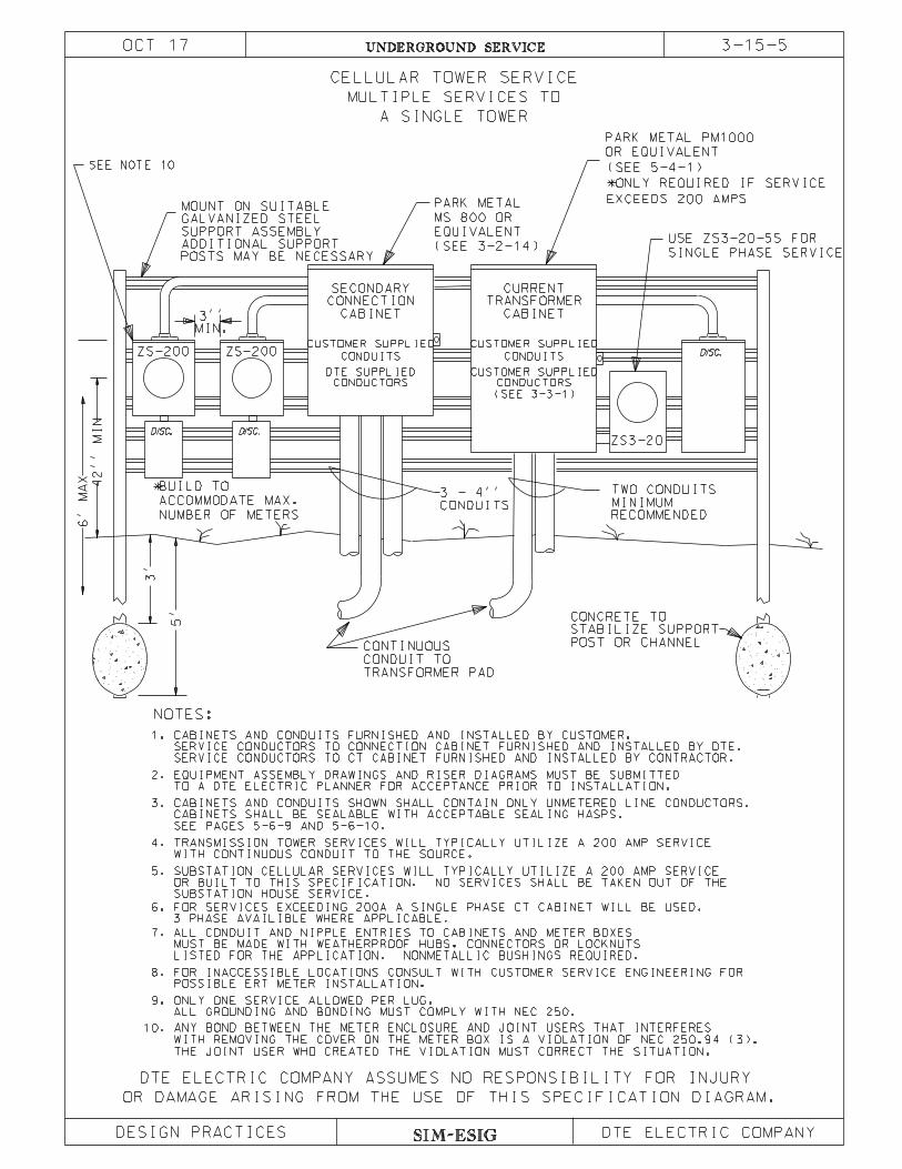
SIM-ESIG
3-15-5UNDERGROUND SERVICE
DESIGN PRACTICES
OR DAMAGE ARISING FROM THE USE OF THIS SPECIFICATION DIAGRAM.
DISC. DISC.
DISC.
CONDUITS
TRANSFORMER PAD
CONDUIT TO
CONTINUOUS
MIN.
3’’
STABILIZE SUPPORT
CONCRETE TO
GALVANIZED STEEL
5’
3’
3 - 4’’
42’’
MI
N
6’
MA
X
ZS-200ZS-200
MOUNT ON SUITABLE
A SINGLE TOWER
MULTIPLE SERVICES TO
CELLULAR TOWER SERVICE
PARK METAL
MS 800 OR
EQUIVALENT
(SEE 3-2-14)
CONNECTION
CABINET
SECONDARY CURRENT
TRANSFORMER
CABINET
ZS3-20
SINGLE PHASE SERVICE
USE ZS3-20-5S FOR
TWO CONDUITS
MINIMUM
RECOMMENDED
SUPPORT ASSEMBLY
POST OR CHANNEL
PARK METAL PM1000
OR EQUIVALENT
(SEE 5-4-1)
NUMBER OF METERS
ACCOMMODATE MAX.
BUILD TO*
CUSTOMER SUPPLIED
CONDUITS
CONDUCTORS CONDUCTORS
CUSTOMER SUPPLIED
CONDUITS
CUSTOMER SUPPLIED
(SEE 3-3-1)
*ONLY REQUIRED IF SERVICE
EXCEEDS 200 AMPS
DTE SUPPLIED
DTE ELECTRIC COMPANY ASSUMES NO RESPONSIBILITY FOR INJURY
DTE ELECTRIC COMPANY
POSTS MAY BE NECESSARY
ADDITIONAL SUPPORT
OCT 17
ALL GROUNDING AND BONDING MUST COMPLY WITH NEC 250.
POSSIBLE ERT METER INSTALLATION.
OR BUILT TO THIS SPECIFICATION. NO SERVICES SHALL BE TAKEN OUT OF THE
WITH CONTINUOUS CONDUIT TO THE SOURCE.
TRANSMISSION TOWER SERVICES WILL TYPICALLY UTILIZE A 200 AMP SERVICE
9.
8.
7.
ONLY ONE SERVICE ALLOWED PER LUG.
NOTES:
5.
4.
3.
2.
1.
FOR INACCESSIBLE LOCATIONS CONSULT WITH CUSTOMER SERVICE ENGINEERING FOR
LISTED FOR THE APPLICATION. NONMETALLIC BUSHINGS REQUIRED.
MUST BE MADE WITH WEATHERPROOF HUBS, CONNECTORS OR LOCKNUTS
ALL CONDUIT AND NIPPLE ENTRIES TO CABINETS AND METER BOXES
EQUIPMENT ASSEMBLY DRAWINGS AND RISER DIAGRAMS MUST BE SUBMITTED
SEE PAGES 5-6-9 AND 5-6-10.
CABINETS SHALL BE SEALABLE WITH ACCEPTABLE SEALING HASPS.
CABINETS AND CONDUITS SHOWN SHALL CONTAIN ONLY UNMETERED LINE CONDUCTORS.
CABINETS AND CONDUITS FURNISHED AND INSTALLED BY CUSTOMER.
SERVICE CONDUCTORS TO CT CABINET FURNISHED AND INSTALLED BY CONTRACTOR.
FOR SERVICES EXCEEDING 200A A SINGLE PHASE CT CABINET WILL BE USED.6.
3 PHASE AVAILIBLE WHERE APPLICABLE.
SUBSTATION HOUSE SERVICE.
SUBSTATION CELLULAR SERVICES WILL TYPICALLY UTILIZE A 200 AMP SERVICE
SERVICE CONDUCTORS TO CONNECTION CABINET FURNISHED AND INSTALLED BY DTE.
TO A DTE ELECTRIC PLANNER FOR ACCEPTANCE PRIOR TO INSTALLATION.
10.
THE JOINT USER WHO CREATED THE VIOLATION MUST CORRECT THE SITUATION.
WITH REMOVING THE COVER ON THE METER BOX IS A VIOLATION OF NEC 250.94 (3).
ANY BOND BETWEEN THE METER ENCLOSURE AND JOINT USERS THAT INTERFERES
SEE NOTE 10

SIM-ESIG
UNDERGROUND SERVICE
DESIGN PRACTICES
OR DAMAGE ARISING FROM THE USE OF THIS SPECIFICATION DIAGRAM.
ILSCO PED3 350-CP
INSULATED PEDESTAL LUGS
5’
EQUIPMENT ASSEMBLY DRAWINGS AND RISER DIAGRAMS MUST BE SUBMITTED
FOR INACCESSIBLE LOCATIONS CONSULT WITH CUSTOMER SERVICE ENGINEERING
1.
2.
3.
NOTES:
CELLULAR TOWER SERVICE
A TRANSMISSION TOWER
ONLY ONE SERVICE ALLOWED PER LUG.
4.
5.
6’
MA
X
42’’
MI
N
3’’
ZINC PLATED UNISTRUT
FORMER PAD
TO POLE OR TRANS-
CONDUIT
CONTINUOUS
CONDUIT
DISC.DISC.
FOR POSSIBLE ERT METER INSTALLATION.
ALL GROUNDING AND BONDING MUST COMPLY WITH NEC 250.
3-15-6
ZS2-200
CONDUIT FURNISHED AND INSTALLED BY CUSTOMER.
ALL CONDUIT AND NIPPLE ENTRIES TO METER BOXES MUST BE MADE WITH
NONMETALLIC BUSHINGS REQUIRED.
WEATHERPROOF HUBS, CONNECTORS OR LOCKNUTS LISTED FOR THE APPLICATION.
350 KCMIL SERVICE CONDUCTORS FURNISHED AND INSTALLED BY DTE.
2X200A MAX SERVICES TO
TO A DTE ELECTRIC PLANNER FOR ACCEPTANCE PRIOR TO INSTALLATION.
DTE ELECTRIC COMPANY ASSUMES NO RESPONSIBILITY FOR INJURY
DTE ELECTRIC COMPANY
CREATED THE VIOLATION MUST CORRECT THE SITUATION.
THE COVER ON THE METER BOX IS A VIOLATION OF NEC 250.94 (3). THE JOINT USER WHO
ANY BOND BETWEEN THE METER ENCLOSURE AND JOINT USERS THAT INTERFERES WITH REMOVING 6.
NOTE 6
OCT 17

03-15-07.dgn 22-Oct-2021 13:04 /u31121
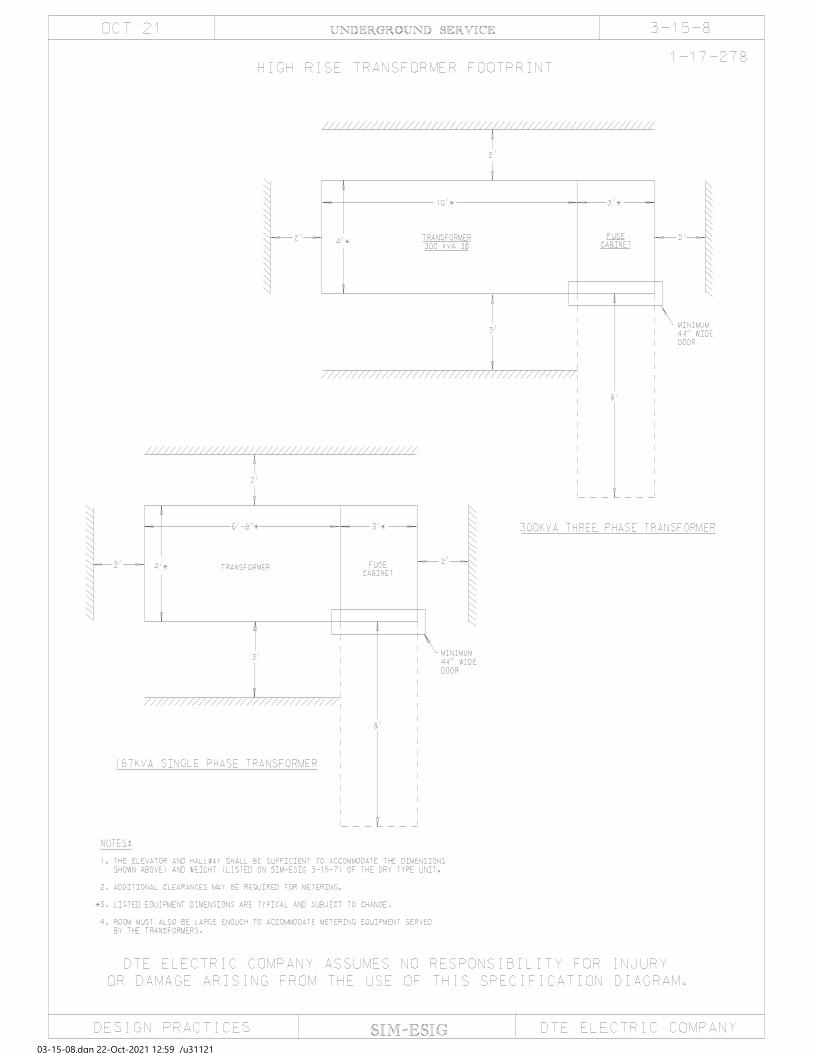
03-15-08.dgn 22-Oct-2021 12:59 /u31121
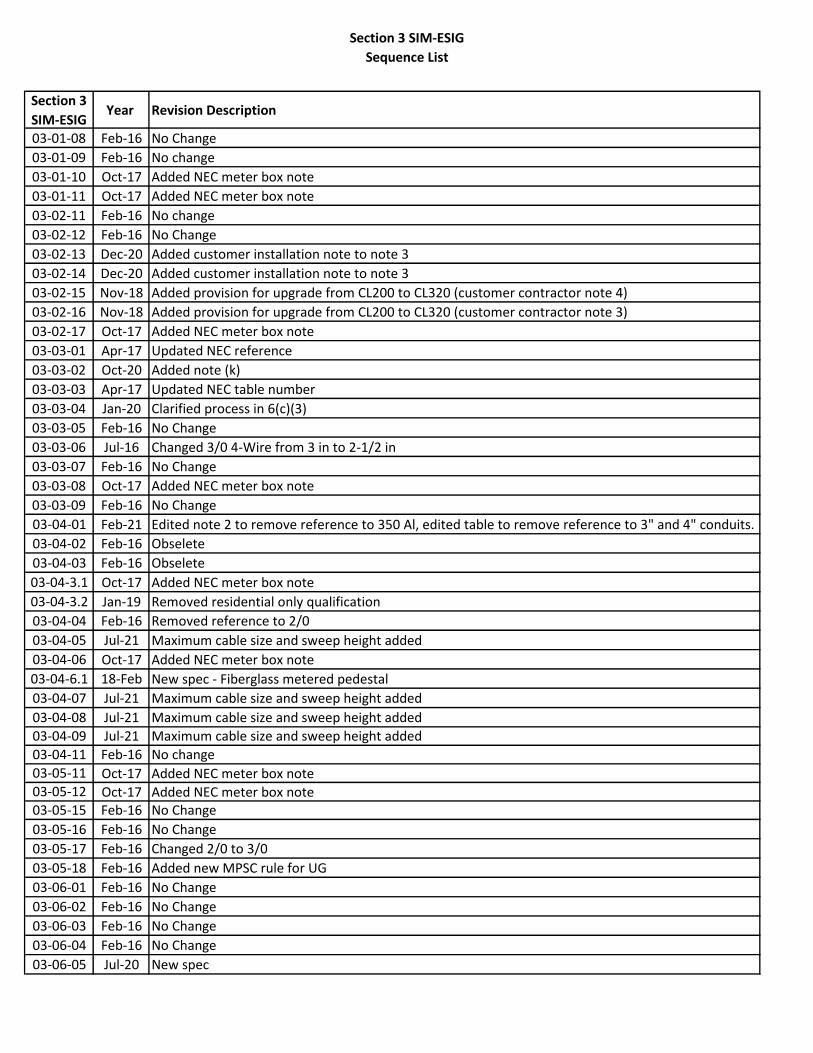
Section 3 SIM-ESIG
Sequence List
Section 3
SIM-ESIGYear Revision Description
03-01-08 Feb-16 No Change
03-01-09 Feb-16 No change
03-01-10 Oct-17 Added NEC meter box note
03-01-11 Oct-17 Added NEC meter box note
03-02-11 Feb-16 No change
03-02-12 Feb-16 No Change
03-02-13 Dec-20 Added customer installation note to note 3
03-02-14 Dec-20 Added customer installation note to note 3
03-02-15 Nov-18 Added provision for upgrade from CL200 to CL320 (customer contractor note 4)
03-02-16 Nov-18 Added provision for upgrade from CL200 to CL320 (customer contractor note 3)
03-02-17 Oct-17 Added NEC meter box note
03-03-01 Apr-17 Updated NEC reference
03-03-02 Oct-20 Added note (k)
03-03-03 Apr-17 Updated NEC table number
03-03-04 Jan-20 Clarified process in 6(c)(3)
03-03-05 Feb-16 No Change
03-03-06 Jul-16 Changed 3/0 4-Wire from 3 in to 2-1/2 in
03-03-07 Feb-16 No Change
03-03-08 Oct-17 Added NEC meter box note
03-03-09 Feb-16 No Change
03-04-01 Feb-21 Edited note 2 to remove reference to 350 Al, edited table to remove reference to 3" and 4" conduits.
03-04-02 Feb-16 Obselete
03-04-03 Feb-16 Obselete
03-04-3.1 Oct-17 Added NEC meter box note
03-04-3.2 Jan-19 Removed residential only qualification
03-04-04 Feb-16 Removed reference to 2/0
03-04-05 Jul-21 Maximum cable size and sweep height added
03-04-06 Oct-17 Added NEC meter box note
03-04-6.1 18-Feb New spec - Fiberglass metered pedestal
03-04-07 Jul-21 Maximum cable size and sweep height added
03-04-08 Jul-21 Maximum cable size and sweep height added
03-04-09 Jul-21 Maximum cable size and sweep height added
03-04-11 Feb-16 No change
03-05-11 Oct-17 Added NEC meter box note03-05-12 Oct-17 Added NEC meter box note03-05-15 Feb-16 No Change
03-05-16 Feb-16 No Change
03-05-17 Feb-16 Changed 2/0 to 3/0
03-05-18 Feb-16 Added new MPSC rule for UG
03-06-01 Feb-16 No Change
03-06-02 Feb-16 No Change
03-06-03 Feb-16 No Change
03-06-04 Feb-16 No Change
03-06-05 Jul-20 New spec
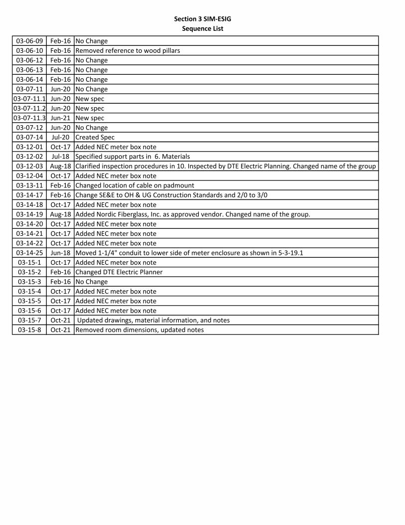
Section 3 SIM-ESIG
Sequence List
03-06-09 Feb-16 No Change
03-06-10 Feb-16 Removed reference to wood pillars
03-06-12 Feb-16 No Change
03-06-13 Feb-16 No Change
03-06-14 Feb-16 No Change
03-07-11 Jun-20 No Change
03-07-11.1 Jun-20 New spec
03-07-11.2 Jun-20 New spec
03-07-11.3 Jun-21 New spec
03-07-12 Jun-20 No Change
03-07-14 Jul-20 Created Spec
03-12-01 Oct-17 Added NEC meter box note
03-12-02 Jul-18 Specified support parts in 6. Materials
03-12-03 Aug-18 Clarified inspection procedures in 10. Inspected by DTE Electric Planning. Changed name of the group
03-12-04 Oct-17 Added NEC meter box note
03-13-11 Feb-16 Changed location of cable on padmount
03-14-17 Feb-16 Change SE&E to OH & UG Construction Standards and 2/0 to 3/0
03-14-18 Oct-17 Added NEC meter box note
03-14-19 Aug-18 Added Nordic Fiberglass, Inc. as approved vendor. Changed name of the group.
03-14-20 Oct-17 Added NEC meter box note
03-14-21 Oct-17 Added NEC meter box note
03-14-22 Oct-17 Added NEC meter box note
03-14-25 Jun-18 Moved 1-1/4" conduit to lower side of meter enclosure as shown in 5-3-19.1
03-15-1 Oct-17 Added NEC meter box note
03-15-2 Feb-16 Changed DTE Electric Planner
03-15-3 Feb-16 No Change
03-15-4 Oct-17 Added NEC meter box note
03-15-5 Oct-17 Added NEC meter box note
03-15-6 Oct-17 Added NEC meter box note
03-15-7 Oct-21 Updated drawings, material information, and notes
03-15-8 Oct-21 Removed room dimensions, updated notes