understanding dvi‐ hdmi and - bicsi tmds? “dvi is the accepted standard for transferring...
TRANSCRIPT

An Introduction To TMDSAn Introduction To TMDS
Understanding DVI D HDMI AndUnderstanding DVI‐D, HDMI And DisplayPort Signals
“For a list of all the ways technology has failed to improve the quality of life, please press three.” ─ Alice Kahn

In This Presentation We Will Explore…
• The Nature of TMDS – What Is It?
• TMDS Applied
• Digital Rights Management
• TMDS, Audio And Control
• TMDS Signal Installation Limitations And Considerations

Why TMDS?
“DVI is the accepted standard for transferring serially uncompressed digital data at high speeds between a PC host and a digital display, such as an LCD monitor. DVI enables a video signal to be transferred from a PC source to a digital display in its native digital form simplifying thebe transferred from a PC source to a digital display in its native digital form, simplifying the way PCs communicate with displays and improving display image quality.”
─ Digital Visual Interface And TMDS Extensions White Paper By Silicon Image (Oct. 2004) • TMDS Transport Leverages The Native Digital Environment Of Fixed Pixel Displays Such
lAs LCD Panels
Eliminates Complex A/D and D/A Conversions• TMDS Is The Only Solution That Supports Very High Resolutions Such As 9 2 MegapixelTMDS Is The Only Solution That Supports Very High Resolutions, Such As 9.2 Megapixel
(3840 x 2400) Displays• TMDS Supports Native 16 Million True‐Color Resolution
8 Bits (Plus 2) Allow 256 Color Shades Per Red, Green and BlueNew Extended Gamut Color (xvYCC) And Deep Color Can Push This To More Than 1 Billion Colors With 10 Bit Implementation (1024 Color Shades Per RGB)

What Is TMDS?

Transition Minimized Differential Signallingg g
• Developed By Silicon Image Inc. As A Member Of The Digital DisplayDeveloped By Silicon Image Inc. As A Member Of The Digital Display Working Group
• TMDS Is A Technology For Transmitting High‐Speed Serial DataTransmitter Incorporates An Advanced Coding Algorithm Which Reduces Electromagnetic Interference Over Copper Cables And Enables Robust ClockElectromagnetic Interference Over Copper Cables And Enables Robust Clock Recovery At The Receiver To Achieve High Skew Tolerance
• TMDS Uses 4 Channels: Red, Green, Blue, Clock• TMDS Is A Two‐stage Process Converts An Input Of 8 Bits Into A 10 Bit Code
TMDS Signalling Uses A Twisted Pair For Noise ReductionCurrent Mode Logic (CML), DC Coupled And Terminated To 3.3 Volts.3 Twisted Pairs Are Used To Transfer Video Data ‐ Each A Different RGB ComponentComponent8‐bit Data Transmission Plus 2 Bits Of Control Signals During Screen Blanking

What Is Transmission Minimization?
• Doesn’t 8‐ To 10‐bit Transition Actually ?Increase Data Rates?
Algorithm Creates A Special 10‐bit Sequence That Minimizes The 0‐to‐1 Transitions, Reducing RF EmissionsTransitions, Reducing RF Emissions
8‐bit Non‐Encoded Requires 7 TransitionsTM Algorithm Reduces This To 3
• Active DC Balancing Minimizes Voltage• Active DC‐Balancing Minimizes Voltage Swings
• Transmits Over Two Wires, Providing All The Benefits Of BalancedAll The Benefits Of Balanced Connectivity
Common Mode Noise Rejection

Hardware Communication


EDID and DDC
• Display Data ChannelDigital Communication Protocols Between A Display And Source That Allows The Display To Communicate Supported Display Modes And Adjust Parameters Such As Brightness And Contrast From The Computer Host
• Extended Display Identification Datap yData Structure Provided DVI And VGA Displays To Describe Capabilities To A Graphics Card256‐byte EDID Structure V1.3 Provides Monitor Name, ID, Model, Serial Number, Display
Size, Aspect Ratio, Horizontal Scanning Frequency Limits, Vertical Frequency Limits, Maximum Resolution, Gamma And Suppurated Video Resolutions
EDID Data Set Is Far More Extensive For HDMI. In Addition To Video Resolutions And Aspect Ratios, It Carries Information About Supported Audio Formats, Data Rates, Bit Depths, Color Space Types, Data Block Types, And More…

Digital Rights Management
“Obviously crime pays, or there'd be no crime.”─ G Gordon LiddyG. Gordon Liddy

HDCP
• High‐Bandwidth Digital Content P t ti P t Th C i OfProtection Prevents The Copying Of Digital Video And Audio Content
Utilizes Blom's Scheme, A Symmetric Threshold Key y yExchange Protocol In Cryptography
• One Source Connected To One Display HDCP Authentication (KeyDisplay, HDCP Authentication (Key Exchange And Validation)
HDMI Protocol Allows For A Single Source To Authenticate M Th O Di lMore Than One Display“One To Many” HDMI Application Is Not Well Supported
http://www.keydigital.com/KnowledgeCenter_HDMIPlugNPlay_wp.html
pp
TMDS Applied‐Digital Visual InterfaceDigital Visual Interface

Digital Video Interface
• DVI‐A Is Analog
• DVI‐I Integrates Analog And Digital
• DVI‐D Is Digital
DVI‐D Dual Link Is Two DVI‐D Single Links In One Assembly
Supports Higher Resolutions AndSupports Higher Resolutions And Higher Refresh Rates

DVI‐D
• R b t L ki C t• Robust, Locking Connector• Single Link Screen Resolution
At 60 HzAt 60 HWUXGA 1920 X 1200HDTV 1920 X 1080WXGA+ 1440 X 900 G 0 900
• Dual Link Screen ResolutionWQXGA 2560 × 1600 @ 60 HzQXGA 2048 × 1536)@ 75QXGA 2048 × 1536)@ 75WUXGA 1920 x 1200 @ 120 Hz

The High Definition “Mystical” Interconnect ‐ HDMIInterconnect HDMI
HDMI
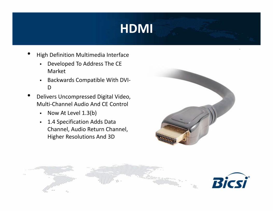
• High Definition Multimedia InterfaceDeveloped To Address The CE e e oped o dd ess e CMarketBackwards Compatible With DVI‐D
• Delivers Uncompressed Digital Video, Multi‐Channel Audio And CE Control
Now At Level 1.3(b) 1.4 Specification Adds Data Channel, Audio Return Channel, Higher Resolutions And 3D
HDMI Adds CE Control and Audio
• CEC Is A One‐wire Bi‐Directional Serial Bus That Uses AV Link Protocol To Perform Remote ControlAV Link Protocol To Perform Remote Control Functions
• HDMI Supports Up To 8 Channels Of Uncompressed pp p pAudio
Up To 24‐bit Word LengthUp To 192 KHz Sampling RateUp To 192 KHz Sampling Rate
• HDMI Now Supports Additional Unique High Definition Audio Algorithms
Dolby TrueHDDTS‐HD

What HDMI CEC Is Supposed To Do…What HDMI CEC Is Supposed To Do…
Press Play on DVDPress Play on DVD
Automatically…Turns on TV
Automatically…Turns on A/V RcvrAnd then…
Plays DVD
Automatically…Switches to correct input
Automatically…Switches to correct inputSwitches to correct input
(from DVD player) Switches to correct input
(from A/V Receiver)

Adding Complexity For The Next GenerationGeneration
An Overview of HDMI 1.4

HDMI 1.4HDMI 1.4
• HDMI Ethernet Channel The HDMI 1.4 specification adds a data channel to the HDMI connection, enabling high‐speed, bi‐directional communication. Connected devices that include this feature can send and receive data via 100 Mb/sec Ethernet making them instantly ready forthis feature can send and receive data via 100 Mb/sec Ethernet, making them instantly ready for any IP‐based application. The HDMI Ethernet Channel allows internet‐enabled HDMI devices to share an internet connection via the HDMI link, with no need for a separate Ethernet cable. It also provides the connection platform that will allow HDMI‐enabled components to share content between devices.
• Audio Return Channel The new specification adds an audio channel that will reduce the• Audio Return Channel The new specification adds an audio channel that will reduce the number of cables required to deliver audio “upstream” from a TV to an A/V receiver for processing and playback. In cases where a TV features an internal content source, such as a built‐in tuner or DVD player, the Audio Return Channel allows the TV to send audio data upstream to the A/V receiver via the HDMI cable, eliminating the need for an extra cable.
3D h i f h ifi i d fi 3 f d l i f• 3D The 1.4 version of the specification defines common 3D formats and resolutions for HDMI‐enabled devices, enabling 3D gaming and other 3D video applications. The specification standardizes the input/output portion of the home 3D system, facilitating 3D resolutions up to dual‐stream 1080p.
• 4K Resolution Support The new specification enables HDMI devices to support extremely pp p pp yhigh HD resolutions, effectively four times the resolution of a 1080p device. Support for 4K allows the HDMI interface to transmit digital content at the same resolution as the state‐of‐the‐art Digital Cinema systems used in many movie theaters.
• Expanded Support For Color Spaces( )• HDMI Micro Connector (Type D)

Local Area NetworkLocal Area NetworkLocal Area NetworkLocal Area Network
• Advanced Bi‐Directional Communications Channels Such As Ethernet And/Or USB
Sharing an Internet ConnectionI t t d USB H bIntegrated USB Hub
Content Distribution – Devices Will Be Able To Exchange Digital Content In Native Format, ,Enabling Recording, Storage, And Playback Options Across A Connected System, With No N d F A S t Eth tNeed For A Separate Ethernet Cable

Audio Return ChannelAudio Return ChannelAudio Return ChannelAudio Return Channel
• Deliver Audio “Upstream” F A TV T A A/V R iFrom A TV To An A/V Receiver For Processing And Playback
In Cases Where A TV Features An Internal ContentFeatures An Internal Content Source, Such As A Built‐in Tuner Or DVD Player, The Audio Return Channel Allows The TV To Send Audio DataThe TV To Send Audio Data Upstream To The A/V Receiver Via The HDMI Cable, Eliminating The Need For An Extra Cablea ab e

TMDS’ New Cousin DisplayPort

DisplayPortDisplayPort
• Digital Display Interface Standard Put h h d lForth By The Video Electronics
Standards Association (VESA) Royalty‐FreeCurrent Version 1 2 Was Approved OnCurrent Version 1.2 Was Approved On December 22, 2009.
• 1, 2, Or 4 Data Pairs In Main Link, Also Carries Clock And Audio Signalsg
Video Signal Path Supports 6 To 16 Bits Per Color ChannelDisplayPort Embeds The Clock In The Data Si nalData Signal
• Not Compatible With HDMI

DisplayPortDisplayPort Cont’dCont’d
• Bi‐directional Auxiliary Channel (At A Constant 17.2 MBit/S) Carries Management And Device Control Data For The Main Link Using VESA EDID And VESA MCCSAnd Device Control Data For The Main Link Using VESA EDID And VESA MCCS (Monitor Control Command Set) Standards
• DisplayPort Technical Advantages:Slimmer Cables, Smaller Connector That Doesn't Require ThumbscrewsBased On Micro‐Packet Protocol, Not Serial Data Stream
Easy Expansion Of The StandardMultiple Video Streams Over Single Physical Connection (Introduced In Version 1.2) Long‐distance Transmission Over Fiber Optic Media
Designed To Support Internal Chip‐to‐chip CommunicationDrives Display Panels Directly, Eliminating Scaling And Control Circuits And Allowing For Cheaper And Slimmer Displays. Will Replace Internal LVDSAllowing For Cheaper And Slimmer Displays. Will Replace Internal LVDS Links
Supports Both RGB And YCbCr Encoding FormatsAuxiliary Channel Can Be Used For Transmitting Bi‐directional USB, Touch‐panel Data Etcpanel Data, Etc.

DisplayPort 1.2
• 3840 X 2400 60hz Resolution3840 X 2400 60hz Resolution• Bi‐directional Data
USB 2.0 or Ethernet
•“Multi‐streaming” — Transport Multiple Independent Display And Audio Streams
2560 x 1600 (WQXGA resolution) is supported over all 2‐meter “DP Certified” cables. Some cables, due to their design, may be capable of supporting 2560 x 1600 resolution over lengths Independent Display And Audio Streams
Over A Single Cable
• Daisy Chain• Hub Configuration
longer than 2 meters
http://www.displayport.org/consumer/?q=content/faq
• (2) 2560 X 1600 Monitors• (4)1920 X 1200 Monitors

Questions ?Questions ?

Thank You!Thank You!