understanding structures, 5th edition derek seward ... resources (by author)/s... · solutions to...
TRANSCRIPT

Solutions to the end of chapter exercises for Understanding Structures fifth edition by Derek Seward © Derek Seward 2014
Understanding Structures, 5th edition
Derek Seward
Solutions to end-of-chapter exercises
Contents Chapter 1 - Design ................................................................................................................................... 2
Chapter 2 - Basics .................................................................................................................................... 9
Chapter 3 - Materials ............................................................................................................................ 12
Chapter 4 - Loads .................................................................................................................................. 16
Chapter 5 – Pin-jointed trusses ............................................................................................................. 18
Chapter 6 - Tension ............................................................................................................................... 20
Chapter 7 - Beams ................................................................................................................................. 24
Chapter 8 - Compression ...................................................................................................................... 30
Chapter 9 – Combined axial and bending stresses ............................................................................... 32
Chapter 10 - Torsion ............................................................................................................................. 36
Chapter 11 - Connections ..................................................................................................................... 38
Chapter 12 – Arches and portal frames ................................................................................................ 41
Chapter 13 – Foundations and retaining walls ..................................................................................... 45
Chapter 14 – Deflection ........................................................................................................................ 50
Chapter 15 – Indeterminate structures and computers ....................................................................... 53

Solutions to the end of chapter exercises for Understanding Structures fifth edition by Derek Seward © Derek Seward 2014
Chapter 1 – Design
E1.1
a. A tree trunk acts as a vertical cantilever beam to
resist wind force. Roots transfer the load into the
ground
b. An apple stalk is a tension member transferring the
weight of the apple back to the tree. Vines and
trailing plants are also tension structures
c. Creatures such as crabs have exo-skeletons. This is
a “shell” structure which provides the strength
and shape on the outside of the flesh.

Solutions to the end of chapter exercises for Understanding Structures fifth edition by Derek Seward © Derek Seward 2014
d. Step ladders are an example of a structure to transfer the
weight of a person down to the ground. The feet are
prevented from moving apart partly by the tensile rope
and partly by friction on the ground.
e. A bed is a similar structure to a bridge and consists of a
beam spanning between compressive columns.
f. The shelf bracket transfers the load back to the wall with
the help of screws. The diagonal member is a compressive
‘strut’ and reduces bending in the bracket.

Solutions to the end of chapter exercises for Understanding Structures fifth edition by Derek Seward © Derek Seward 2014
E1.2
a1. Steel lattice tower with tension guys.
a2. Concrete shell with restaurant.
b1. Shell dome with flying buttresses.
b2. Cable-supported ‘tent’ roof (cross-section)

Solutions to the end of chapter exercises for Understanding Structures fifth edition by Derek Seward © Derek Seward 2014
E1.3
Stage 1 – site survey
Determine the most suitable point to cross the stream taking into account:
Stream width
Height of banks
Foundation material (any mid-stream rocks for extra support?)
Location of access roads.
Carry out a detailed survey and
produce a cross-section of the chosen
point – drawn to scale:
Stage 2 – alternative concepts
Comments:
a. Best appearance and long life, but expensive and difficult,
b. Reasonably good appearance, fairly cheap and easy but possibly short life,
c. Robust and easy but requires maintenance for long life,
d. Least attractive but cheap and easy.
Choose say b.

Solutions to the end of chapter exercises for Understanding Structures fifth edition by Derek Seward © Derek Seward 2014
Stage 3 – detailed development
Stage 4 - Assessment of loads
This can be tricky and very much depends upon who has access to the bridge. Is it accessible by the
public and emergency vehicles? If this is the case the bridge will need to be designed for loads
specified in Eurocode 1-2. If the bridge merely provides a link between two fields and will only be
used by the farmer for movement of animals and a tractor and trailer the load requirements may be
more relaxed. The local building regulation authority should be contacted for advice.
Assuming use by only the farmer:
Animals: Design for say the number of cows that can fit on the bridge x weight of
one cow. (about 1000 kg each?). Side load, P, on the handrail might be 20% of
cow weight?
Vehicles: The highest axle loads should be placed at various points in
the span.
Stage 5 Analysis
Structural model:

Solutions to the end of chapter exercises for Understanding Structures fifth edition by Derek Seward © Derek Seward 2014
Stage 6 – detail design
possible failure
modes:

Solutions to the end of chapter exercises for Understanding Structures fifth edition by Derek Seward © Derek Seward 2014
E1.4
a. Permissible stress design
Total load in rod = 12 + 16 = 28 kN
Area required = force/stress = 28 x 103/150
= 187 mm2
b. Limit state design
Design permanent load = 12 x 1.35 = 16.2 kN
Design variable load = 16 x 1.5 = 24.0 kN
Total design load = 40.2 kN
Design strength = fy/M = 275/1.0 = 275 N/mm2
Area required = 40.2 x 10³/275 = 146 mm2

Solutions to the end of chapter exercises for Understanding Structures fifth edition by Derek Seward © Derek Seward 2014
Chapter 2 - Basics
E2.1
a. Force from 2.0 kg weight = 2.0 x 9.81 = 19.6 N
Force from 3.5 kg weight = 3.5 x 9.81 = 34.3 N
Structural model:
b. Horizontal component of force = 34.3 cos 30° = 29.7 N
Vertical component of force = 19.6 + 34.3 sin 30° = 36.8 N
c. Magnitude of resultant force = (29.72 + 36.82) = 47.3 N
Direction of resultant force = tan-1(36.8/29.7) = 51.1°
d. Stress in cable = Force/Area = 34.3/ (π x 1.52/4)
= 19.4 N/mm2
30°
30°
19.6 N
30°
51.1°

Solutions to the end of chapter exercises for Understanding Structures fifth edition by Derek Seward © Derek Seward 2014
E2.2
a. FCH = 20 Cos 30° = 17.32 kN
FCH = 20 Sin 30° = 10.0 kN
b.
Support B is a roller RBH = 0
M about A
(17.32 x 0.75) + (10 x 3.5) = RBV x 2.0
RBV = 24.0 kN
H = 0 RAH = 17.32 kN
V = 0 10.0 + RAV = 24.0 kN
30°
FCH
FCV
C
RAH
RAV
RBH
RBV
17.32
10.0

Solutions to the end of chapter exercises for Understanding Structures fifth edition by Derek Seward © Derek Seward 2014
RAV = 14.0 kN
E2.3
No horizontal forces or reactions
a. M about A
10 x 3 = 5 x RA
RA = 6 kN
V = 0
10 = 6 + RC
RC = 4 kN i.e. tension in rod
structural model:
b. Area of rod = π x 102/4 = 78.5 mm2
Stress = force/area = 4 x 10³/78.5 = 51 N/mm2
c. Extension, = FL/EA where E = 205 kN/mm2
= 4 x 103 x 3000/205 000 x 78.5 = 0.75 mm
10.0
A
B
C
RC
RA

Solutions to the end of chapter exercises for Understanding Structures fifth edition by Derek Seward © Derek Seward 2014
Chapter 3 - Materials
E3.1
a. Underground water storage reservoir
Choice: Reinforced concrete
Reasons:
Will resist bending from water pressure
Can be made waterproof with additives
Durable and requires no maintenance if cover to reinforcement adequate
Relatively cheap
Can be formed on-site from locally available materials
b. Footbridge in chemical plant
Choice: Fibre composite
Reasons:
Resistant to chemical attack
No maintenance required
Lightweight and easily transported
c. Portable grandstand
Choice: Aluminium alloy
Reasons:
Lightweight and easily transported
Good range of extrusions available
Can be welded
Can be painted or anodised for good corrosion protection
Stiffer than fibre composite

Solutions to the end of chapter exercises for Understanding Structures fifth edition by Derek Seward © Derek Seward 2014
E 3.2
a. Yield stress, fy, and Modulus of elasticity, E
b. Gauge length is the initial length of the specimen for the purposes of measuring extension
and hence strain and modulus of elasticity.
c. Plastic behaviour means that materials are ductile. ( i.e. they can be deformed by large
amounts without losing their strength. The opposite of brittle.
d. Because by the time mild steel has reached its ultimate strength it will have deformed
excessively. Keeping below the yield strength means that permanent deformations do not
take place.
e. Yield point (i.e. start of plastic behaviour), limit of proportionality (i.e. end of linear
behaviour where strain is proportional to stress) and elastic limit (i.e . end of reversible
deformation).

Solutions to the end of chapter exercises for Understanding Structures fifth edition by Derek Seward © Derek Seward 2014
E3.3
Area of specimen = π/4 x 52 = 19.63 mm2
Stress = load/area
% Strain = 100 x extension/gauge length
Load (kN) Extension (mm) Stress (N/mm2) % Strain
0.00 0.00 0 0.000
1.00 0.01 51 0.025
2.00 0.02 102 0.050
3.00 0.03 153 0.075
4.00 0.04 204 0.100
5.00 0.05 255 0.125
5.32 0.06 271 0.150
5.38 0.07 274 0.175
5.34 0.08 272 0.200
From graph:
a. Yield stress, fy = 274 N/mm2
b. Modulus of elasticity, E = 204/0.001 = 204 000 N/mm2
0
50
100
150
200
250
300
0 0.05 0.1 0.15 0.2 0.25
Stre
ss N
/mm
2
strain %
Stress/strain curve
204
273
3

Solutions to the end of chapter exercises for Understanding Structures fifth edition by Derek Seward © Derek Seward 2014
E3.4
Result (x) (x-xm) (x-xm)2
455 -4 16
467 8 64
449 -10 100
452 -7 49
471 12 144
462 3 9
2756 382
Mean x m = 2756/6 = 459
Standard deviation = [(x-xm)2/(n-1)] = 382/5
= 8.74
Characteristic strength = 459 – 1.59 x 8.74
= 445 N/mm2
Design strength = Characteristic strength/M
= 445/1.15 = 387 N/mm2

Solutions to the end of chapter exercises for Understanding Structures fifth edition by Derek Seward © Derek Seward 2014
Chapter 4 - Loads
E4.1
From table 4.1 unit weight of steel = 70 kN/m3
Weight of of 1 square meter of plate 6 mm thick = 70 x 0.006 = 0.42 kN/m2
a. Characteristic permanent load = 0.42 kN/m2
b. From table 4.3 variable floor load for factory = 5.0 kN/m2
Total design load = (1.35 x 0.42) + (1.5 x 5.0)
= 8.07 kN/m2
E4.2
a.
Resultant occurs at centroid of triangle i.e. 1/3rd of height.
a. Force = 38.25 x 4.5/2 = 86.1 kNm
b. Bending moment = 86.1 x 1.5 = 129.2 kNm

Solutions to the end of chapter exercises for Understanding Structures fifth edition by Derek Seward © Derek Seward 2014
E4.3
Area of each floor = 60 x 60 = 3600 m2
From table 4.1 Wt. of floor/m2 = 25 x 0.2 = 5 kN/m2
Wt. of one entire floor = 3600 x 5 = 18 000 kN
Wall area per storey = 4 x 4 x 60 = 960 m2
Weight of wall per storey = 960 x 1.0 = 960 kN
Total permanent load/storey = 18 000 + 960 = 18 960 kN
From table 4.3 Variable load per floor = 3600 x 2.5 = 9000 kN
Total design load = 110 x [(1.35 x 18 960) + ( 1.5 x 9000)]
= 4.30 x 10⁶ kN
E4.4
The following is for a 1 m wide strip of the floor (into the page):
From table 4.1 Permanent load of wall = 22 x 0.215 x 1.0 = 4.73 kN/m
Design permanent wall load = 4.73 x 1.35 = 5.81 kN/m
Permanent load of slab = 25 x 0.3 = 7.5 kN/m
Design permanent slab load = 1.35 x 7.5 = 10.1 kN/m
From table 4.3 Variable load on slab = 2.5 kN/m
Design variable load = 1.5 x 2.5 = 3.75 kN/m
Total slab design load = 10.1 + 3.75 = 13.85 kN/m
Load on beam is reaction at A - take moments about B:
RA x 8.0 = (5.81 x 9.8) + (13.85 x 9.8 x 9.8/2)
RA = 90.25 kN/m
Design self-weight of beam = 140 x 9.81/103 x 1.35 = 1.9 kN/m
Total design load on beam = 90.25 + 1.9 = 92.15 kN/m
5.81 kN
A B
13.85 kN/m
kN
8.0 m 1.8 m Structural model

Solutions to the end of chapter exercises for Understanding Structures fifth edition by Derek Seward © Derek Seward 2014
Chapter 5 – Pin-jointed trusses
E5.1
E5.2
E5.3
cut

Solutions to the end of chapter exercises for Understanding Structures fifth edition by Derek Seward © Derek Seward 2014
Consider only the left-hand-side of the cut:
M about E for FBC:
FBC x yE = RA x 8
FBC x 4.85 = 260 x 8
FBC = 429 kN compression
M about x for FCE:
(180 x 20) = (260 x 12) + (FCE x 16.64)
FCE = 28.8 kN tension
E5.4
a. m = 13, j = 6 i(1)
b. m = 11, j = 5 + reduced roller support, but formula doesn’t work – actually m + i(1)
c. m = 16, j = 8 extra roller i(1)
d. m = 8, j = 4 s
e. m = 11, j = 5 i(1)
Solutions to the end of chapter exercises for Understanding Structures fifth edition by Derek Seward © Derek Seward 2014
Chapter 6 - Tension
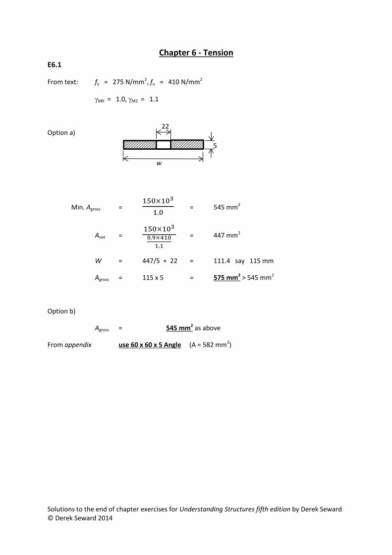
E6.1
From text: fy = 275 N/mm2, fu = 410 N/mm2
M0 = 1.0, M2 = 1.1
Option a)
Min. Agross =
= 545 mm2
Anet =
= 447 mm2
W = 447/5 + 22 = 111.4 say 115 mm
Agross = 115 x 5 = 575 mm2 > 545 mm2
Option b)
Agross = 545 mm2 as above
From appendix use 60 x 60 x 5 Angle (A = 582 mm2)
22
2
22
w
5

Solutions to the end of chapter exercises for Understanding Structures fifth edition by Derek Seward © Derek Seward 2014
E6.2
From symmetry consider only half of the structure:
a.
= tan-1(2/3) = 33.7°
From vertical equilibrium:
vertical component of force F2 = 2 kN
F2 Sin33.7° = 2.0
Force in cable at support, F2 = 3.60 kN
From horizontal equilibrium:
Force in cable at midspan, F1 = 3.60Cos 33.7° = 3.00 kN
b.
Area of cable required = 3600/(1200/5) = 15 mm2
Diameter = (15x4/π) = 4.4 mm
Use 5mm diameter cable
F1
F2
2 kN
2
3

Solutions to the end of chapter exercises for Understanding Structures fifth edition by Derek Seward © Derek Seward 2014
E6.3
Total design load = (1.35 x 6) + (1.5 x 5 x 2) [where 2 is the width)
= 23.1 kN/m
[6.4] RV = wL/2 = 23.1 x 64/2 = 739 kN
[6.5] RH = wL2/8D = (23.1 x 642)/(8 x 15) = 788 kN
a. Max cable force at support = 0.5 x (7392 + 7882) = 540 kN
[0.5 above is because of two cables]
b. Compressive force in tower = vert. component in cables at each side
= 2 x 739 = 1478 kN
c. Area of cable required = Force/(strength/M) = 540 x 103/(1590/3)
= 1019 mm2
Diameter = [(4 x 10¹⁹)/π] = 36.02 mm
say 40 mm
d.Horizontal force on cable anchor = RH/2 = 788/2 = 394 kN
RV
RH
RH
15.0
32.0
23.1 kN/m
Diagram identical for both main
span and side-spans

Solutions to the end of chapter exercises for Understanding Structures fifth edition by Derek Seward © Derek Seward 2014
E6.4
Design variable load from one light = 2.5 x 1.5 x 9.81 = 368 N
a.
M about A
(368 x 1.3) + (368 x 4.7) = (368 x 0.7) + (RB x 4.4)
RB = 443 N
V = 0
RA = (3 x 368) – 443
= 661 N
b.
Area of wire required = 661/(300/5) = 11.01 mm2
Diameter of wirte = [(4 x 11.01)/π] = 3.75 say 4.0 mm

Solutions to the end of chapter exercises for Understanding Structures fifth edition by Derek Seward © Derek Seward 2014
Chapter 7 - Beams
E7.1

Solutions to the end of chapter exercises for Understanding Structures fifth edition by Derek Seward © Derek Seward 2014

Solutions to the end of chapter exercises for Understanding Structures fifth edition by Derek Seward © Derek Seward 2014
E7.2
Bending moment = wl2/8 = 22 x 8.02 /8 = 176 kNm
fy = 275, M = 1.0
required Wpl = (176 x 106)/(275 x 103) = 640 cm3
Use 406 x 140 x 39 kg/m Universal Beam
E7.3
a.
Total area = 9 + 6 + 6
= 21cm2
Half area = 21/2
= 10.5 cm2
For the plastic modulus the neutral axis divides the
total area into two equal parts.
Y = 1.0 + (10.5 – 6)/0.8 = 6.625 cm
Plastic modulus, Wpl = 81.3 cm3
b.
Design load = (1.35 x 0.9) + (1.5 x 3.5) = 6.47 kN/m2
Design load/m, w = 6.47 x 0.35 = 2.26 kN/m
c.
Design bending moment = wl2/8 = 2.26l2/8
Design resistance moment = Wpl x fy = 81.3 x 275/103
= 22.36
Equating and
2.26l2/8 = 22.36
lmax = 8.9 m
Item A (cm2) Y (cm) Ay (cm3)
1 9 3.375 30.3
2 1.5 0.938 1.4
3 4.5 2.813 12.7
4 6 6.125 36.8
81.3

Solutions to the end of chapter exercises for Understanding Structures fifth edition by Derek Seward © Derek Seward 2014
E7.4
a. Design load = 10 x 1.5 = 15 kN
Lever arm, l = 0.8 cos 45°
= 0.566 m
M about A:
15 x 1.7 = FBD x 0.566
Force in ram, FBD = 45.1 kN
M about E:
15 x 1.7 = RF x x2.2
RF = 11.59 kN
V = 0:
15 = 11.59 + RE
RE = 3.41 kN
c.
Mmax = 15 x 0.9 = 13.5 kNm
Wpl required = (13.5 x 10⁶)/(275 x 103)
= 49.1 cm3
From appendix:
Use 100 x 100 x 4.0 square hollow section (Wpl = 54.9 cm3)
15
15

Solutions to the end of chapter exercises for Understanding Structures fifth edition by Derek Seward © Derek Seward 2014
E7.5
Part Area (mm2 ) yn A yn y Ay2 Iself
Rectangle 600 20 12000 1.51 1368 80 000
Hole -78.5 30 -2355 11.51 -10400 -491
521.5 9645 -9032 79 509
Y = 9645/521.5 = 18.49
INA = 79 509 – 9032 = 70 477 mm4
Wel,top = 70 477/ (40-18.49) = 3276 mm3
Wel,bottom= 70 477/ 18.49 = 3812 mm3
top = 0.5 x 10⁶/3276 = 153 N/mm2 compression
bottom = 0.5 x 10⁶/3812 = 131 N/mm2 tension
E7.5
a. Effective depth, d = 450 – 30 12.5 = 407.5 mm
But MEd = wl2/8 = 40l2/8
l = 8 x 139.3/40) = 5.28 m span
b. Shear force on beam, VEd = 5.28 x 40/2 = 105.6 kN
Design shear stress, vEd = 105.6 x 10³/(200 x 407.5) = 1.30 N/mm2
200
407.5
Based on concrete:
Mult = 0.214 fckbd2 = 0.214 x 30 x 200 x 407.52 x 10-6
= 213.2 kNm
Based on reinforcement:
Table 3.1 Area of steel = 2 x 491
= 982 mm2
Mult = 0.696 Asfykd = 0.696 x 982 x 500 x 407.5 x 10-6
= 139.3 kNm

Solutions to the end of chapter exercises for Understanding Structures fifth edition by Derek Seward © Derek Seward 2014
% reinforcing steel = 100 As/bd
= 100 x 982/(200 x 407.5) = 1.2
Interpolating from table 7.2 vRd,c = 0.71 N/mm2 < 1.30 – shear links required
New , vED = 105.6 x 10³/(200 x 407.5 x 0.9)
= 1.44 N/mm2
From table 7.3 (cot = 2.5) vRd,max = 5.28 > 1.30
Asw = vEdsb /1087 = 1.44sb/1087
Max link spacing, s = 0.75 x 407.5 = 305.6
Say = 300 mm
Asw = 1.44 x 300 x 200/1087
= 79.5 mm2
From table 3.1 Use 8 mm dia. Links at 300 mm spacing (Asw = 100 mm2)

Solutions to the end of chapter exercises for Understanding Structures fifth edition by Derek Seward © Derek Seward 2014
Chapter 8 - Compression
E8.1
From equation 8.1 NRd = fck/c × b × hw × (1 – 2e/hw)
Where: Eccentricity, e = lw/400 = 3750/400
= 9.4 mm
NRd = 40/1.5 × 400 × 400 × (1- 2 × 9.4/400) x 10-3
= 4066 kN
E8.2
For 10mm x 10mm strut, I = bd3 /12 = 10 x 103 /12 = 833 mm4
`For steel , E = 210 000 N/mm2
Euler buckling load , Pcrit = π2EI/L2 = π2x 210 000 x 833/9002
= 2130 N
E8.3
Design load = 250/2 x 1.5 = 187.5 kN
Approximate area = 187.5 x 10³ /100 x 102 = 18.7 cm2
From appendix Try 114.3 x 6.3 circular hollow section (A = 21.4 cm2 , i = 3.82 cm)
Effective length = 3500 x 2 = 7000 mm
Non-dimensional slenderness, = 7000/(86 x 38.2) = 2.13
From fig 7.38 = 0.18
Buckling stress = 275 x 0.18 = 49.5 N/mm2
Actual stress = 187.5 x 10³ /21.4 x 102 = 87.6 N/mm2
– no good
From appendix Try 168.3 x 5.0 circular hollow section (A = 5.7 cm2 , i = 5.78 cm)

Solutions to the end of chapter exercises for Understanding Structures fifth edition by Derek Seward © Derek Seward 2014
Non-dimensional slenderness, = 7000/(86 x 57.8) = 1.4
From fig 7.38 = 0.38
Buckling stress = 275 x 0.38 = 104.5 N/mm2
Actual stress = 187.5 x 10³ /25.7 x 102 = 73 N/mm2
Use 168.3 x 5.0 circular hollow section

Solutions to the end of chapter exercises for Understanding Structures fifth edition by Derek Seward © Derek Seward 2014
Chapter 9 – Combined axial and bending stresses
E9.1
Axial load, NEd = 675 + 450 + 590
= 1715 kN
Approx. area required = 1715 x 103/100 x 102
= 172 cm2
Try 305 x 305 x 137 Universal Column
(A = 175 cm2, Wpl,y = 2300 cm3, Wpl,z = 1052 cm3, iz= 7.82 cm,
h = 320.5, tf = 13.8)
Dimensions as shown
MyEd = (675 – 590) x (0.160 + 0.1)
= 22.1 kNm
MzEd = 450 x (0.007 + 0.1)
= 48.2 kNm
Non-dimensional slenderness ratio, = LE/(86 x iz) = 6000/(86 x 78.2)
= 0.89
From [9.2] NEd My,Ed Mz,Ed
Afy LTfyWpl,y fyWpl,z
From fig 7.38 = 0.55
Buckling stress = 0.55 x 275 = 151 N/mm2
Bending stress = 0.55 x 275 = 151 N/mm2
Axial resistance, Afy = 175 x 151 x 10-1 = 2642 kN
y-y bending resistance, LTfyWpl,y= 151 x 2300 x 10-3 = 347 kNm
z-z bending resistance, fyWpl,z = 275 x 1052 x 10-3 = 289 kNm
substitute into equation [9.2]
1715 22.1 48.2 63 < 1.0
2642 347 Use 305 x 305 x 137 Universal Column

Solutions to the end of chapter exercises for Understanding Structures fifth edition by Derek Seward © Derek Seward 2014
E9.2 a.
Item Area (cm2)
yn
(cm)
A yn y Ay2 Iself
1 4.0 9.5 38 5.48 120 -
2 6.4 5.0 32 0.98 6 34
3 8.0 0.5 4 3.52 99 1
18.4 74 225 35
Y = 74/18.4 = 4.02 cm
INA = 225 + 44 = 260 cm4
Wel,inner = 260/4.02 = 64.7 cm3
Welouter = 260/(10-4.02) = 43.5 cm3
b. Total load = (30 x 70) + 2000 = 4100 kg
Force = 4100 x 9.81/103 = 40.2 kN
Eccentricity,e = 0.26 +0.042 = 0.30 m
Moment = 40.2 x 0.30 = 12.06 kNm
= F/A M/Wel
inner = 40.2 x 10³/18.4 x 102 + 12.06 x 10⁶ /64.7 x 103
= 21.8 + 186.4 = 208.2 N/mm2 tens.
inner = 40.2 x 10³/18.4 x 102 - 12.06 x 10⁶ /43.5 x 103
= 21.8 – 276.0 = 254.2 N/mm2 comp.

Solutions to the end of chapter exercises for Understanding Structures fifth edition by Derek Seward © Derek Seward 2014
E9.3 Elastic moduli: Wel,top = 18 000/10 = 1800 cm3 Wel,bottom = 18 000/15 = 1200 cm3 Sagging BM:
bottom = 24 x 106/1200 x 103 = 20 N/mm2 tension
Hogging BM:
top = 9 x 10⁶/1800 x 103 = 5 N/mm2 tension
Required pre-stress -
Stress at N.A. level = 5 + (15 x 10/25) = 11 N/mm2
pre-stressing force = 11 x 200 x 102/103 = 220 kN
Consider top stresses, top = P/A - Pe/ Wel,top = 5
5 = 11 -220 x 103 x e/1800 x 103
5 = 11 – 0.122e
e = 49.2 mm
Check bottom stresses, bottom = 11 + 220 x 103 x 49.2/1200 x 103
= 11 + 9.02 = 20.02 N/mm2 - check

Solutions to the end of chapter exercises for Understanding Structures fifth edition by Derek Seward © Derek Seward 2014
E9.4
INA = BD3/12 – bd3/12
= 3 x 33/12 – 1.8 x 1.83/12
= 6.75 – 0.875
= 5.875 m4
Elastic modulus, Wel = 5.875/1.5
= 3.917 m3
Area of section = 32 – 1.82
= 5.76 m2
Total weight = 30 x 5.76 x 20
= 3456 kN
Total wind force = 30/2 x 1.3 x 3.0
= 54 kN
Resultant acts 2/3 of height up chimney:
= 2/3 x 30
= 20 m
Overturning moment = 54 x 20
= 1080 kNm
Stresses at base = F/A M/Wel
= 3456/5.76 1080/3.917
= 600 276 kN/m2
= 0.876 N/mm2 Compressive
And
= 0.324 N/mm2 Compression

Solutions to the end of chapter exercises for Understanding Structures fifth edition by Derek Seward © Derek Seward 2014
Chapter 10 - Torsion
E10.1
Tult = 2yR3/3
= 2 x 159 x x 153/3
= 1 124 000 Nmm
= 1.12 kNm
= L/GR
= (3000 x 90)/(77 000 x 15)
= 0.234 rad
= 13.4°
E10.2 a. Area of sign = 1.8 x 0.9 = 1.62 m2 Design load = 1.62 x 1.1 = 1.782 kN Bending moment = 1.782 x 2.8 = 4.98 kNm Torque = 1.782 x (0.4 + 0.9/2) = 1.51 kNm b. Plastic modulus for bending, Wpl = 4.98 x 10⁶/275 x 103 = 18.1 cm3 Try 60 x 60 x 4.0 square hollow section (Wpl = 18.6 cm3)
bending shear = 1782/(2 x 60 x 4) = 3.7 N/mm2 Am = 56 x 56 = 3136 mm2
Equation [10.6] torsion shear = T/2Amt = 1.51 x 10⁶/(2 x 3136 x 4) = 60.2 N/mm2
total = 3.7 + 60.2 = 63.9 N/mm2 < 159
Use 60 x 60 x 4.0 square hollow section

Solutions to the end of chapter exercises for Understanding Structures fifth edition by Derek Seward © Derek Seward 2014
E10.3
a.
Equation [10.7] max = 3T/at2 Where a = 145 + 70 = 215 mm
max = 3 x 1.2 x 106/(215 x 102)
= 167 N/mm2
b.
= 3TL/at3G =
= 0.870 rad = 49.8°

Solutions to the end of chapter exercises for Understanding Structures fifth edition by Derek Seward © Derek Seward 2014
Chapter 11 - Connections
E11.1 a. based on gross area of tie – equation [6.2] NRd = 70 x 10 x 275/103 = 192.5 kN
based on net area of tie – equation [6.3] NRd = (70-24) x 10 x 0.9 x 410/(1.1 x 103) = 154.3 kN b. based on shear capacity - equation [11.3] Fv = 2 x 0.6 x 400 x π x 112 x 10-3/1.25 = 146.0 kN c. based on bearing capacity - equation [11.4] Fb = 2 x 400 x 22 x 10 x 10-3/1.25 = 140.8 kN Design resistance, NRd = 140.8 kN
E11.2 a. based on gross area of tie – equation [6.2]- as above NRd = 70 x 10 x 275/103 = 192.5 kN
based on net area of tie – equation [6.3] NRd = (70-22) x 10 x 0.9 x 410/(1.1 x 103) = 161.0 kN b. based on slip resistance - equation [11.5] Fv = 2 x 0.7 x 1 x 0.5 x 800 x 245 x 10-3/1.25 = 109.80 kN c. based on bearing capacity - equation [11.4] Fb = 2 x 400 x 20 x 10 x 10-3/1.25 = 128 kN Design resistance, NRd = 109.8 kN

Solutions to the end of chapter exercises for Understanding Structures fifth edition by Derek Seward © Derek Seward 2014
E11.3
Item A(cm2) yn (cm) Ayn(cm3) Y (cm) Ay2 (cm4) Iself (cm4)
Plate 60 53.8 3228 17.4 18166 20
Beam 104 26.6 2746 10.0 10400 47500
164 5974 28566 47520
Ŷ = 5974/164 = 36.4 cm INA = 28566 + 47520 = 76086 cm4 Equation [11.9] shear flow/weld, q = VQ/I = 2500 x 60 x 17.4/76086 = 17.15 kN/cm = 1.72 kN/mm From table 10.1 Use 12 mm fillet weld (strength = 1.87 N/mm)
E11.4
Item A(cm2) yn (cm) Ayn(cm3) Y (cm) Ay2 (cm4) Iself (cm4)
Plate 300 0.5 150 8.45 21421 -
Beams 205.2 21.3 4371 12.35 31298 55800
505.2 4521 52719 55800
Ŷ = 4521/505.2 = 8.95 cm INA = 52 719 + 55 800 = 108 519 cm4 a. Wpl,top = 108 519/8.95 = 12 125 cm3 Wpl,bottom = 108 519/(41.6-8.95) = 3 324 cm3 For critical BM put load at midspan: MRd = PL/4 = 150 x 8/4 = 300 kNm
comp = 300 x 106/12 125 x 103 = 25.0 N/mm2

Solutions to the end of chapter exercises for Understanding Structures fifth edition by Derek Seward © Derek Seward 2014
tens = 300 x 106/3 324 x 103 = 90.3 N/mm2 b. For critical shear put load adjacent to support: VRd = 150 kN shear flow, q = VQ/I = 150 x 103 x 300 x 8.45/108 519 = 3504 N/cm But this is resisted by 6 welds: Shear flow/weld = 3504/(6 x 10) = 58.4 N/mm

Solutions to the end of chapter exercises for Understanding Structures fifth edition by Derek Seward © Derek Seward 2014
Chapter 12 – Arches and portal frames
E12.1
M about A: (600 x 8) +(600 x 16) + (2400 x 24) = RE x 32 RE = 2250 kN
V =0: 600 + 600 + 2400 = 2250 + RA
RA = 1350 kN
M about C: (2400 x 8) + (HE x 6) = 2250 x 16 HE = 2800 kN
H =0: HA = -2800 kN a.
MB = (1350 x 8 ) – (2800 x 6) = -6000 kNm – tension in top
b. MD = (2800 x 6 ) – (2250 x 8) = -1200 kNm – tension in bottom LDE = 5 m For thrust resolve forces parallel to DE: Thrust = 2250 x 3/5 + 2800 x 4/5 = 3590 kN For shear resolve forces perpendicular to DE: Shear = 2250 x 4/5 - 2800 x 3/5 = 120 kN

Solutions to the end of chapter exercises for Understanding Structures fifth edition by Derek Seward © Derek Seward 2014
E12.2
M about A: (20 x 4) +(40 x 4) + (80 x 8) + (40 x12) = (RBV x 12) + (RBH x 1) 1360 = 12RBV + RBH
M about D: (40 x 4) + (RBH x 3) = RBV x 4 160 = 4RBV - 3RBH x 3 480 = 12RBV - 9RBH - 880 = 10RBH
RBH = 88 kN Sub in 1360 = 12RBV + 88 RBV = 106 kN
V =0: 40 + 80 + 40 = 106 + RAV
RAV = 54 kN
H =0:
RAH + 20 = 88 RAH = 68 kN MC = (63 x 4) – (68 x 4) = -56 kNm (tension in top) ME = (88 x 3) = 264 kNm (tension in top) Thrust AC = 54 cos 45° + 68 cos 45° = 86.3 kN (compression) Shear AC = 54 cos 45° - 68 cos 45° = -9.9 kN

Solutions to the end of chapter exercises for Understanding Structures fifth edition by Derek Seward © Derek Seward 2014
E12.3
M about A: (2.5 x 6 x 3) +(6.5 x 16 x 8) + (1.2 x 6 x3) = RBV x 16 RBV = 56.2 kN M about D: (6.5 x 8 x 4) +( RBH x 7) = (56.2 x 8) +(1.2 x 6 x 4) RBH = 38.6 kN
V =0: 6.5 x 16 = 56.2 + RAV
RAV = 47.8 kN
H =0: (2.5 x 6) +(1.2 x 6 ) + RAH = 38.6 RAH = 16.4 kN
Design values:
MRd = 210 kNm
NRd = 56.2 kN

Solutions to the end of chapter exercises for Understanding Structures fifth edition by Derek Seward © Derek Seward 2014
E12.4
Using equations 6.1 to 6.3
Reactions RAV = RBV = wL/2 = 40 x 20/2 = 400 kN Reactions RAH = -RBH = wL2/8D = 40 x 202/(8x4) = 500 kN
Maximum force in arch = (4002 + 5002) = 640.3 kN Approximate area required = 640.3 x 10³/150 x 102 = 42.7 cm2 Try 152 x 152 x 37 Universal Column (iz= 3.87 cm, A = 47.4 cm2)
Non-dimensional slenderness ratio, = 2000/(86 x 38.7) = 0.60
From figure 7.38 = 0.76
NRd = 0.76 x 47.4 x 275 = 991 kN>640.3
Try a smaller size:
Try 152 x 152 x 30 Universal Column (iz= 3.82 cm, A 38.2 cm2)
Non-dimensional slenderness ratio, = 2000/(86 x 38.2) = 0.61
From figure 7.38 = 0.75
NRd = 0.75 x 38.2 x 275 = 788 kN>640.3
Use 152 x 152 x 30 Universal Column

Solutions to the end of chapter exercises for Understanding Structures fifth edition by Derek Seward © Derek Seward 2014
Chapter 13 – Foundations and retaining walls
E13.1 Total unfactored load = 350 + 275 = 625 kN
table 13.1 - stiff clay , bearing pressure, gd = 200 kN/m2
Area of foundation = 625/200 = 3.125 m2
For a square, width = 3.125 = 1.77 m say 1.8 m Projection = 0.9 -0.2 = 0.7 m From section 13.5.2 Depth, say = 0.75 m
E13.2 For reinforced concrete pad use same plan dimensions as above but only 300 mm deep. Design column load, NRd = (1.35 x 350) + (1.5 x 275) = 885 kN Ground pressure, q = 885/1.82 = 273 kN/m2 Design moment, MRd = 0.5 x 273 x 1.8 (1.8/2 -0.4/2)2 = 120 kNm Estimate 12 mm dia. Bars Effective depth, d = 300 – 40 -12 -6 = 242 mm K = M/bd2fck = 120 x 106/(1800 x 2422 x 30) = 0.04 From figure 7.47 z/d = 0.95 z = 0.95 x 242 = 230 mm As = M/fyz = 120 x 106/(500/1.15 x 230) = 1200 mm2 Number of 12 mm bars = 1200/113 = 11 1.5(c + 3d) = 1.5(0.4 + 3 x 0.242) = 1.69 m < 1.8 m
put 2/3 of bars in middle band

Solutions to the end of chapter exercises for Understanding Structures fifth edition by Derek Seward © Derek Seward 2014
Width of band = C + 3d = 0.4 + (3 x 0.242) = 1.13 m Number of bars in band = 2/3 x 11 = 7 Spacing within band = 1130/6 = 188 mm But spacing if evenly spaced = (1800-80)/10 = 172 mm
Use even spacing Shear across pad Shear force, VEd = q x L x L/ 2 – C/2 – d) = 273 x 1.8 x (0.9 – 0.2 – 0.242) = 225 kN Shear area = L x d = 1800 x 242 = 435 600 mm2
Shear stress, vEd = VEd/(L x d) = 225 x 103/435 600 = 0.52 N/mm2 100 As/bd = (100 x 1200)/(1800 x 242) = 0.28
From table 7.2 vRd,c = 0.54 > 0.52 – no shear reinforcement required. Punching shear Check at the face of the column:
Shear stress, vEd = ( )
=
( )
= 2.17 N/mm2
From table 7.3 vRd,max = 5.28 N/mm2 > 2.17 N/mm2
Check at a = d:
Shear stress, vEd = ( )
( )
= ( )
( )
= 0.961 N/mm2
From shear across pad vRd,c = 0.54 N/mm2
vRd, = 0.54 × 2d/d
= 1.08 N/mm2 > 0.961 N/mm2

Solutions to the end of chapter exercises for Understanding Structures fifth edition by Derek Seward © Derek Seward 2014
Check at a = 2d:
Shear stress, vEd = ( )
( )
= ( )
( )
= 0.413 N/mm2
From above vRd,c = 0.54 N/mm2
vRd = 0.54 × 2d/2d
= 0.54 N/mm2> 0.413 N/mm2
Proposed dimensions and reinforcement are satisfactory

Solutions to the end of chapter exercises for Understanding Structures fifth edition by Derek Seward © Derek Seward 2014
E13.3
M about A:
Distance from A to centre of mass = 45.5/64.5 = 0.705 m Distance from base centre = 0.705 – 0.625 = 0.080 m
Soil pressure at base = Kasz = 0.33 x 20 x 2.5 = 16.5 kN/m2 Active force = 16.5/2 x 2.5 = 20.63 kN Overturning moment = 20.63 x 2.5/3 = 17.2 kNm Eccentiicity, er = 17.2 – (64.5 x 0.08)/64.5 = 0.187 m Distance to edge of mid. 1/3rd = 1.25/6 = 0.208 m>0.187 m i.e. resultant is within middle third
max = F/A + Fer/Wel = 64.5/1.25+64.5 x 0.187/(1 x 1.252/6) = 51.6 + 37.1 = 88.7 kN/m2
Sliding: Active force = 20.63 kN Friction = 64.5 x 0.6 = 38.7 kN
Passive resistance force = Kpsz2/2 = 3 x 20 x 0.52/2 = 7.5 kN
Factor of safety = (38.7 + 7.5)/20.63 = 2.24
E13.4 Pressure behind wall becomes:
Ka’z = 0.33 x (20 – 9.81) x 2.5 = 3.36 kN/m2
wz = 9.81 x 2.5 = 24.53 kN/m2 Total pressure = 3.36 + 24.53 = 27.89 kN/m2
Force = 27.89/2 x 2.5 = 34.9 kN Moment = 34.9 x 2.5/3 = 29.1 kNm Er = 29.1 – (64.5 0.08)/64.5 = 0.37 m > 0.208 m i.e outside middle third
Item Weight (kN) Distance (m) Moment (kNm)
1 1.0 x 2.5 x 24 = 60.0 0.750 45.0
2 0.25 x 0.75 x 24 = 4.5 0.125 0.5
64.5 45.5

Solutions to the end of chapter exercises for Understanding Structures fifth edition by Derek Seward © Derek Seward 2014
x = d/2 - er = 0.625 – 0.37 = 0.255
max = 2 x 64.5/(3 x 0.255) = 169 kN/m2
Sliding:
Factor of safety = (38.7 + 7.5)/34.9 = 1.32

Solutions to the end of chapter exercises for Understanding Structures fifth edition by Derek Seward © Derek Seward 2014
Chapter 14 – Deflection
E14.1

Solutions to the end of chapter exercises for Understanding Structures fifth edition by Derek Seward © Derek Seward 2014
E = 7000
Member L (mm) A (mm2) FL (N) =
(mm) Fu Fu
AD 3606 5000 14 400 -1.48 -0.60 0.89
DC 3606 5000 10 800 -1.11 -0.60 0.67
CE 3606 5000 10 800 -1.11 -1.20 1.33
EB 3606 5000 14 400 -1.48 -1.20 1.78
BG 4000 5000 12 000 1.37 1.00 1.37
GF 4000 5000 6 000 0.69 0.50 0.35
FA 4000 5000 12 000 1.37 0.50 0.69
DF 2236 5000 6 700 -0.43 0 0.00
FC 4472 5000 6 700 0.86 0 0.00
CG 4472 5000 6 700 0.86 1.12 0.96
GE 2236 5000 6 700 -0.43 0 0.00
= 8.04
Deflection = 8.04 mm
E14.2 from appendix: I = 18 600 cm4 E = 205 000 N/mm2 Use superposition:
Deflection, =
=
= 17.3 + 7.4
= 24.7 mm

Solutions to the end of chapter exercises for Understanding Structures fifth edition by Derek Seward © Derek Seward 2014
E14.3
Aluminium, E = 70 000 N/mm2 - table 3.3
2nd mom. Area, I = R4/4 - r4/4 - figure 7.31
= /4 (604 - 584) = 1.29 x 106 mm4
= PL3/3EI = 150 x 60003/(3 x 70 000 x 1.29 x 106) = 120 mm
E14.4 Table 3.1 As = 3 x 491 = 1473 mm2 Effective depth, d = 500 – 40 - 10 – 12.5 = 437.5 mm % reinforcement = 100 x 1473/(300 x 437.5) = 1.12% Table 14.1 by interpolation: Basic span/depth ratio = 6.76 Maximum span = 6.76 x 437.5 = 2960 mm say 3.0 m

Solutions to the end of chapter exercises for Understanding Structures fifth edition by Derek Seward © Derek Seward 2014
Chapter 15 – Indeterminate structures and computers
E15.1 a. Each crossed member (2) adds a redundancy plus additional internal roller supports (2) – answer – 4. b. Simple cantilever is statically determinate so internal roller supports add two redundancies - answer – 2 c. A Three-pin portal is statically determinate so making two pins into rigid joints adds two redundancies - answer – 2
E15.2
M about A: -267 + (300 x 2) + 133 – 6RB = 0 RB = 78 kN
` V = 0 RA = 300 – 78 = 222 kN MC = 267 –(222 x 2) = 177 kNm
Design moment, MEd = 267 kNm (i.e. biggest moment on beam)
Wpl = 267 x 106/275 x 103 (M = 1.0) = 971 cm3 Use 406 x 178 x 54 kg/m universal beam (Wpl = 1050 cm3)
E15.3
MP(2 + 3 + ) = 300 x 4 6MP = 1200
MP = 200 kNm
Wpl = 200 x 106/275 x 103 (M = 1.0) = 727 cm3 Use 406 x 140 x 39 kg/m universal beam (Wpl = 724 cm3) % reduction = (54-39)/54 x 100 = 27.8%