uni-axial and multi-axial creep behaviour of p91-type steel under constant load
TRANSCRIPT

Engineering Failure Analysis 18 (2011) 61–67
Contents lists available at ScienceDirect
Engineering Failure Analysis
journal homepage: www.elsevier .com/locate /engfai lanal
Uni-axial and multi-axial creep behaviour of P91-type steelunder constant load
Aleš Nagode a,⇑, Ladislav Kosec a, Boris Ule b
a Faculty of Natural Sciences and Engineering, Aškerceva cesta 12, 1000 Ljubljana, Sloveniab Institute of Metals and Technology, Lepi pot 11, 1000 Ljubljana, Slovenia
a r t i c l e i n f o a b s t r a c t
Article history:Received 8 July 2010Received in revised form 11 August 2010Accepted 12 August 2010Available online 16 August 2010
Keywords:Short-term creepUni-axial creep testMulti-axial creep testConstant loadMonkman–Grant relationship
1350-6307/$ - see front matter � 2010 Elsevier Ltddoi:10.1016/j.engfailanal.2010.08.005
⇑ Corresponding author. Fax: +386 14704560.E-mail addresses: [email protected]
The uni-axial and multi-axial creep behaviour of P91-type steel under constant load wasstudied. The conventional, uni-axial, constant-load creep tests were performed at initialstresses ranging from 120 MPa to 240 MPa, and at temperatures from 625 to 675 �C, whilethe multi-axial, small-punch, constant-load creep tests were performed at loads rangingfrom 350 N to 550 N, and at temperatures from 650 to 690 �C. Both types of test can be con-sidered as short-term creep tests because the maximum time-to-rupture was less than500 h. Since it is well known that the creep behaviour of P91-type steel cannot be satisfac-torily described by a simple, Arrhenius-type, power-law constitutive model, an improvedstress-dependent, energy-barrier model was used for a description of the uni-axial as wellas the multi-axial creep behaviour of the P91-type steel. It was found that the obtained val-ues of the apparent activation energies Qc during the uni-axial and multi-axial creep testswere very close, and in both types of test they were considerably higher than the activationenergy for the lattice diffusion in iron.
� 2010 Elsevier Ltd. All rights reserved.
1. Introduction
Creep tests can be conducted either at constant load or at constant stress. However, from the engineering point of view,constant-load creep tests are more important than constant-stress creep tests, because it is the load and not the stress that isnormally kept constant in engineering applications. When studying the creep properties of materials, the most conventionaltests are uni-axial creep tests using cylindrical specimens [1–3]. However, in some cases it is not possible to have availablethe large amount of material required for a conventional cylindrical specimen. Therefore, some new testing techniques arebeing developed: tests that are able to extract the mechanical properties from a specimen with a small volume [4,5]. One ofthese tests is the so-called miniaturised disc-bend test, also known as the small-punch test. This technique can also be usedto measure the creep properties [6]. In the small-punch creep test a thin, circular disc is supported over a recessed hole andforced under constant load to deform into the hole by means of a spherically shaped punch or a ceramic ball. This gives riseto a rotationally symmetrical, multi-axially stressed state in the specimen, in contrast to the conventional uni-axial creeptest, where a multi-axially stressed state occurs with the formation of the neck in the specimen. However, this happens dur-ing a very late stage of the creep test, just before the rupture. Thus, it has almost no influence on the time-to-rupture.
P91-type steel is widely used for the high-temperature pipework components in advanced power plants. It exhibits a con-siderable high-temperature creep strength, a high corrosion-cracking resistance, a low oxidation rate, and good weldability
. All rights reserved.
(A. Nagode), [email protected] (L. Kosec).

62 A. Nagode et al. / Engineering Failure Analysis 18 (2011) 61–67
[7–11]. However, due to the characteristics of P91-type steel, the creep behaviour of this steel cannot be accurately describedusing a simple, Arrhenius-type power law:
_emin ¼ Arn exp �Q c
RT
� �ð1Þ
where _emin is the minimum creep rate, r is the applied stress, Qc is the apparent activation energy, G is the shear modulus(G [MPa] = 97,400–0.039T), n is the stress exponent, T is the absolute temperature, R is the universal gas constant(R = 8.314 J mol�1K�1), and A is a constant.
However, the improved, power-law, stress-dependent, energy-barrier model (Eq. (2)) developed by Ule and Nagode[12,13] has been quite successful at describing the creep behaviour of P91-type steel under constant stress since a good cor-relation between calculated values and experimental data has been obtained.
_emin ¼ C1rG
� �nexp �Qc max � C2ðr=GÞ
RT
� �ð2Þ
where Qc max is the limiting value of the apparent activation energy when r ? 0, and C1 and C2 are constants.In order to find a creep equation that would satisfactorily describe the uni-axial as well as the multi-axial creep behaviour
of P91-type steel under constant load a large number of short-term creep tests, i.e., conventional uni-axial and small-punchcreep tests that give rise to a rotationally symmetrical, multi-axially stressed state in the specimen, were carried out. Theobtained values of the apparent activation energies and stress exponents will help make it possible to understand the dom-inant rate-controlling mechanism of the supposed multiple creep mechanism during the uni-axial as well as the multi-axialcreep test.
2. Experimental procedure
P91-type steel with the chemical composition 0.104 C, 0.30 Si, 0.43 Mn, 9.01 Cr, 0.01 Ni, 0.95 Mo, 0.22 V, 0.06 Nb andbalance Fe (all values in wt.%) was used in our research. In order to homogenise the microstructure, the investigated steelwas subjected to an additional two-stage heat treatment (1050 �C for 1 h, vacuum cooling +750 �C for 1 h, vacuum cooling).The initial, tempered martensite ferritic, microstructure of the investigated steel is shown in Fig. 1. The specimens for theuni-axial creep tests were cut along the axial direction of the pipe. The diameter of the specimen was 6 mm and the gaugelength was 50 mm. The discs for the small-punch multi-axial creep test were cut from the same pipe in such a way that thenormal to the disc surface was parallel to the axis of the pipe. The diameter of the disc test specimens was 8 mm and thick-ness was 0.50 mm. All the discs were ground and polished to 1200 grit.
The conventional uni-axial creep tests were conducted at initial stresses ranging from 120 MPa to 240 MPa and at tem-peratures of 625, 650 and 675 �C, while the small-punch, multi-axial tests were performed at temperatures of 650, 675 and690 �C and at loads from 350 to 550 N. For each of the test conditions at least three measurements were made in both cases.The temperature of the cylindrical specimen was measured with a thermocouple at three points in the direct vicinity of thespecimen, while the temperature of the disc was measured with a thermocouple, placed as close as possible to the specimen.The changes in the specimen’s length (uni-axial creep tests) or the displacement of the punch, i.e., the central deflection ofthe disc specimens (small-punch creep tests) were measured using an inductive transducer with a high measuring accuracy(repeatability approximately 1 lm) and were recorded continuously by a computer. Both types of tests were performed in aprotective atmosphere of purified argon. All the tests were run to the final fracture.
Fig. 1. Tempered martensite ferritic microstructure of the investigated P91-type steel.
A. Nagode et al. / Engineering Failure Analysis 18 (2011) 61–67 63
3. Results and discussion
3.1. Conventional uni-axial creep tests
For the description of the creep behaviour of the P91-type steel an improved power-law, stress-dependent, energy-barriermodel (Eq. (2)) was used. Monkman and Grant [14] (Eq. (3)) found a relationship between the minimum creep rate ð _eminÞ andthe time-to-rupture (tr) based on the following equation:
Fig
tr ¼ M � e�pmin ð3Þ
where M and p are the Monkman–Grant constants.Hence, the relationship between the experimentally obtained minimum creep rate ( _emin) and the time-to-rupture (tr) at
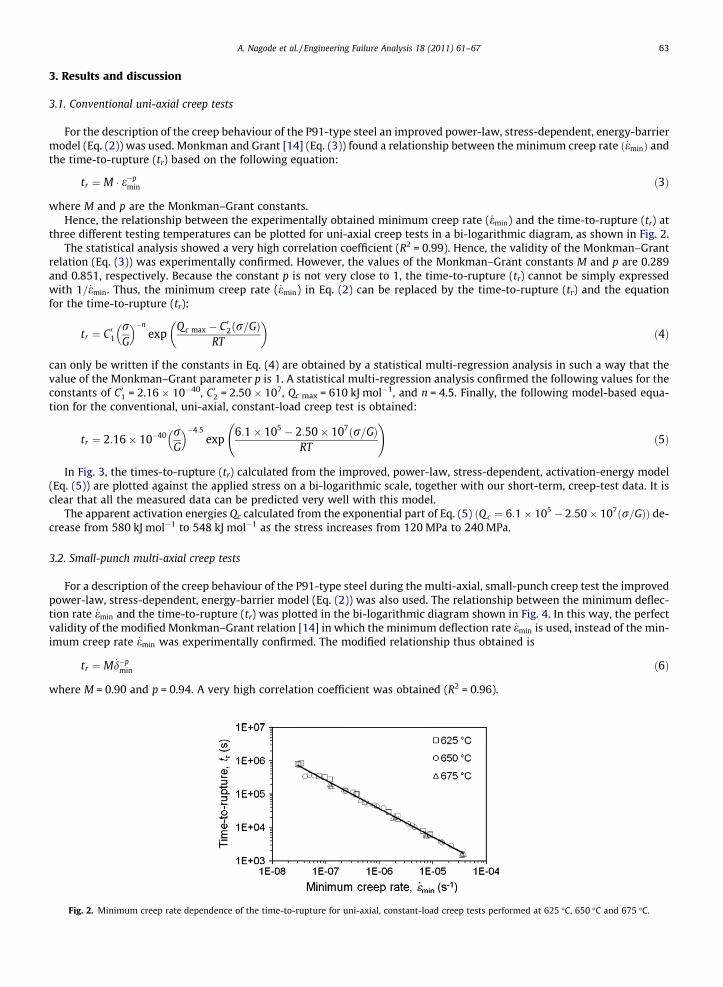
three different testing temperatures can be plotted for uni-axial creep tests in a bi-logarithmic diagram, as shown in Fig. 2.The statistical analysis showed a very high correlation coefficient (R2 = 0.99). Hence, the validity of the Monkman–Grant
relation (Eq. (3)) was experimentally confirmed. However, the values of the Monkman–Grant constants M and p are 0.289and 0.851, respectively. Because the constant p is not very close to 1, the time-to-rupture (tr) cannot be simply expressedwith 1= _emin. Thus, the minimum creep rate ( _emin) in Eq. (2) can be replaced by the time-to-rupture (tr) and the equationfor the time-to-rupture (tr):
tr ¼ C 01rG
� ��nexp
Q c max � C 02ðr=GÞRT
� �ð4Þ
can only be written if the constants in Eq. (4) are obtained by a statistical multi-regression analysis in such a way that thevalue of the Monkman–Grant parameter p is 1. A statistical multi-regression analysis confirmed the following values for theconstants of C01 = 2.16 � 10�40, C02 = 2.50 � 107, Qc max = 610 kJ mol�1, and n = 4.5. Finally, the following model-based equa-tion for the conventional, uni-axial, constant-load creep test is obtained:
tr ¼ 2:16� 10�40 rG
� ��4:5exp
6:1� 105 � 2:50� 107ðr=GÞRT
!ð5Þ
In Fig. 3, the times-to-rupture (tr) calculated from the improved, power-law, stress-dependent, activation-energy model(Eq. (5)) are plotted against the applied stress on a bi-logarithmic scale, together with our short-term, creep-test data. It isclear that all the measured data can be predicted very well with this model.
The apparent activation energies Qc calculated from the exponential part of Eq. (5) ðQ c ¼ 6:1� 105 � 2:50� 107ðr=GÞÞ de-crease from 580 kJ mol�1 to 548 kJ mol�1 as the stress increases from 120 MPa to 240 MPa.
3.2. Small-punch multi-axial creep tests
For a description of the creep behaviour of the P91-type steel during the multi-axial, small-punch creep test the improvedpower-law, stress-dependent, energy-barrier model (Eq. (2)) was also used. The relationship between the minimum deflec-tion rate _emin and the time-to-rupture (tr) was plotted in the bi-logarithmic diagram shown in Fig. 4. In this way, the perfectvalidity of the modified Monkman–Grant relation [14] in which the minimum deflection rate _emin is used, instead of the min-imum creep rate _emin was experimentally confirmed. The modified relationship thus obtained is
tr ¼ M _d�pmin ð6Þ
where M = 0.90 and p = 0.94. A very high correlation coefficient was obtained (R2 = 0.96).
. 2. Minimum creep rate dependence of the time-to-rupture for uni-axial, constant-load creep tests performed at 625 �C, 650 �C and 675 �C.
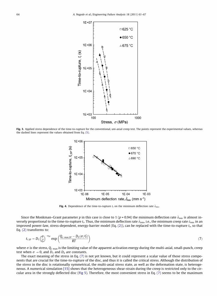
Fig. 3. Applied stress dependence of the time-to-rupture for the conventional, uni-axial creep test. The points represent the experimental values, whereasthe dashed lines represent the values obtained from Eq. (5).
Fig. 4. Dependence of the time-to-rupture tr on the minimum deflection rate _dmin.
64 A. Nagode et al. / Engineering Failure Analysis 18 (2011) 61–67
Since the Monkman–Grant parameter p in this case is close to 1 (p = 0.94) the minimum deflection rate _dmin is almost in-versely proportional to the time-to-rupture tr. Thus, the minimum deflection rate _dmin, i.e., the minimum creep rate _emin in animproved power-law, stress-dependent, energy-barrier model (Eq. (2)), can be replaced with the time-to-rupture tr, so thatEq. (2) transforms to:
tr;SP ¼ D1rG
� ��nSP
expQc max;SP � D2ðr=GÞ
RT
� �ð7Þ
where r is the stress, Qc max is the limiting value of the apparent activation energy during the multi-axial, small-punch, creeptest when r ? 0, and D1 and D2 are constants.
The exact meaning of the stress in Eq. (7) is not yet known, but it could represent a scalar value of those stress compo-nents that are crucial for the time-to-rupture of the disc, and thus it is called the critical stress. Although the distribution ofthe stress in the disc is rotationally symmetrical, the multi-axial stress state, as well as the deformation state, is heteroge-neous. A numerical simulation [15] shows that the heterogeneous shear-strain during the creep is restricted only to the cir-cular area in the strongly deflected disc (Fig 5). Therefore, the most convenient stress in Eq. (7) seems to be the maximum

Fig. 5. Shear-strain distribution in the thin disc during the small-punch creep test [15].
A. Nagode et al. / Engineering Failure Analysis 18 (2011) 61–67 65
effective stress for which the von Misses effective stress was adopted as well as the assumption that not the spherical part,but only the deviatoric part, of the stress tensor has an influence on the creep behaviour. The value of this stress is notknown, since only the load P is measured for a particular disc thickness and geometry of the small-punch testing device.
Since Milicka and Dobeš [16,17] experimentally determined the linear dependence between the stress r during a conven-tional, uni-axial, tensile creep test and the load P during a small-punch creep test, which results in an identical time-to-rup-ture tr:
Fig. 6.values
P ¼ kr ð8Þ
Eq. (5) can be rearranged to:
tr;SP ¼ D1P
D3
� �nSP
expQ c max;SP � P=D2
RT
� �ð9Þ
where P is the applied load when measuring the creep properties of the disc, and D1, D2 and D3 are constants, Qc max;SP is theapparent activation energy for a small-punch creep test, i.e., the limiting value of the activation energy when P ? 0, and nSP isthe load exponent.
Correlation of the model (Eq. (10)) with the experimental data. The points represent the experimental values, whereas the dashed lines represent theobtained from Eq. (10).

66 A. Nagode et al. / Engineering Failure Analysis 18 (2011) 61–67
The values of the constants D1, D2 and D3 as well as the apparent activation energies Q c max;SP and the load exponents nSP
were obtained by means of a statistical, multi-regression analysis and are D1 = 2.95 � 10�16, D2 = 2.04 � 10�2, D3 = 2.87,Qc max;SP = 560 kJ mol�1 and nSP = 4.5.
The final equation for the multi-axial, small-punch creep is then
tr;SP ¼ 2:95� 10�16 P2:87
� ��4:5
exp5:6� 105 � P=2:04� 10�2
RT
!ð10Þ
In Fig. 6, the times-to-rupture calculated from Eq. (10) are plotted against the applied loads on a bi-logarithmical scaletogether with our short-term, multi-axial, small-punch creep data. It is clear that there is a good correlation between themodel and the experimental data.
The apparent activation energies Qc for the small-punch creep test calculated from the exponential part of Eq. (10)ðQ c ¼ 5:6� 105 � P=2:04� 10�2Þ decrease from 543 kJ mol�1 to 533 kJ mol�1 as the load increases from 350 N MPa to550 N. These values of the apparent activation energies as well as the values obtained during the conventional uni-axialcreep tests are in good agreement with the literature data [18–20].
4. Conclusions
Two different types of creep test for the P91-type steel under constant load were carried out, i.e., conventional uni-axialcreep tests, where cylindrical specimens are used, and miniaturised, multi-axial, small-punch creep tests, where thin discsare used.
The relationship between the minimum creep rate during the uni-axial, conventional, constant-load creep test and theminimum deflection rate during the multi-axial, constant-load creep test against the time-to-rupture was studied. The valid-ity of the Monkman–Grant relation was experimentally confirmed in both cases. However, the Monkman–Grant parameter pduring the multi-axial creep test was very close to 1 (p = 0.94), while during the uni-axial creep test p is somewhat less than1 (p = 0.851).
Since it is well known that the creep behaviour of the P91-type steel cannot be properly described by a simple, Arrheniuspower-law, the improved power-law, stress-dependent, energy-barrier model was used to describe both types of tests. Usingthis model the measured times-to-rupture can be very accurately predicted in the case of the conventional uni-axial creeptest as well as in the case of the multi-axial, small-punch creep test. The improved model is theoretically well founded sinceit assumes the stress dependence of the energy barrier.
The stress exponent n obtained during the uni-axial creep test and the load exponent nSP obtained during the multi-axial,small-punch creep test were, in both cases, 4.5, and this is not too high for climb-controlled creep. This value is somewhatsmaller than the values from the literature [18–20], where the stress exponent defined as @ ln _emin
@ ln r
� �strongly depends on the
temperature and may, thus, increase from 8 to approximately 16 as the temperature decreases from 650 �C to 550 �C. In thecase of the uni-axial, constant-load creep test the apparent activation energies calculated from the time-to-rupture de-creased from 580 kJ mol�1 to 548 kJ mol�1 as the stress increased from 120 to 240 MPa, whereas in the case of the multi-ax-ial, small-punch creep test the activation energies decreased from 543 kJ mol�1 to 533 kJ mol�1 as the load increased from350 to 550 N. These values of the apparent activation energies are in good agreement with the literature data [18–20]; how-ever, they are significantly higher than the activation energy for self-diffusion in a-iron. They represent the activation energyof the slowest, dominant rate controlling process of the supposed multiple creep mechanism. The reason for the slightly low-er activation energies in the case of the multi-axial, small-punch creep tests probably lies in the increasing dislocation den-sity because of the high plastic deformation at the onset of the creep measurement.
Acknowledgment
The experimental work was conducted at The Institute of Metals and Technology, Lepi pot 12, SI-1000, Ljubljana.
References
[1] Aktaa J, Schinke B. Creep lifetime under constant load and constant stress: theory and experiment. J Test Eval 1996;24(4):212–28.[2] André Meyers M, Kumar Chawla K. Mechanical behaviour of materials. New Jersey: Prentice Hall; 1999. p. 543–4.[3] Nagode A, Ule B, Jenko M, Kosec L. A constitutive creep equation for 9Cr–1Mo–0.2V (P91-type) steel under constant load and constant stress. Steel Res
Int 2007;78(8):638–42.[4] Lucas GE. The development of small specimen mechanical test techniques. J Nucl Mater 1983;117:327–39.[5] Lucas GE. Review of small specimen test techniques for irradiation testing. Metall Trans A 1990;21A:1105–19.[6] Ule B, Šturm R, Leskovšek V. Effects of test specimen geometry on creep behaviour of 12Cr steel in miniaturised disc bend tests. Mater Sci Technol
2003;19:1771–6.[7] Blum W, Straub S. Subgrain growth during creep of a tempered martensitic 12% Cr-steel. Steel Res 62;1991:72-74.[8] Jones WB, Hills CR, Polonis DH. Microstructural evolution of modified 9Cr–1Mo steel. Metall Trans 1991;22A:1049–58.[9] Hald J. Metallurgy and creep properties of new 9–12%Cr steels. Steel Res 1996;67:369–74.
[10] Kosec B, Kosec G. Temperature field analysis on active working surface of the die-casting die. Metall (Berl. West) 2003;57(3):134–6.[11] Vojvodic-Tuma J, Kosec G. Effect of microstructure on the accelerated creep of 20CrMoV12-1 and P 91 steels. Steel Res Int 2007;78(8):643–7.[12] Ule B, Nagode A. A model based creep equation for 9Cr–1Mo–0.2V (p91 type) steel. Mater Sci Technol 2007;23(11):1367–74.

A. Nagode et al. / Engineering Failure Analysis 18 (2011) 61–67 67
[13] Ule B, Nagode A. The improved power-law, stress-dependent, energy-barrier model of 9Cr–1Mo–0.2V steel using short-term creep data. Scripta Mater2007;57:405–8.
[14] Monkman FC, Grant NJ. An empirical relationship between rupture life and minimum creep rate in creep-rupture test. Proc ASTM 1956;56:593–605.[15] Ule B, Šuštar T, Lovrencic Sarazin M, Rodic T. Copernicus-small punch test method assessment for the determination of residual creep life of service
exposed,}small punch}. Twelve month progress report period 1.2.1996–31.1.1997. Project documentation classification code: 12MPR2_(IMT Ljubljana).Ljubljana: IMT; 1997.
[16] Milicka K, Dobeš F. Relation between uniaxial and equi-biaxial creep and creep fracture behaviour in P91 steel. Mater Sci Forum 2005;482:407–17.[17] Milicka K, Dobeš F. Small punch testing of P91 steel. Int J Press Ves Pip 2006;83:625–34.[18] Sklenicka V, Kucharová K, Dlouhy A, Krejci J. Materials for advanced power engineering. Dordrecht: Kluwer; 1994.[19] Cadek J, Šustek V, Pahutová M. An analysis of a set of creep data for a 9Cr–1Mo–0.2V (P91 type) steel. Mater Sci Eng 1997;225A:22–8.[20] Spigarelli S, Cerri E, Bianchi P, Evangelista E. Interpretation of creep behaviour of a 9Cr–Mo–Nb–V–N (T91) steel using threshold stress concept. Mater
Sci Techol 1999;15:1433–40.