unidrive m: general purpose ac drives - industrial automation · 4 unidrive m model unidrive...
TRANSCRIPT
Unidrive M: General Purpose AC Drives
Unidrive M100-M400Easy-to-use, flexible and reliable
0.33 - 200 hp (0.25 - 132 kW)
115 V | 208-240 V | 380-480 V | 575 V | 690 V
2 www.controltechniques.com
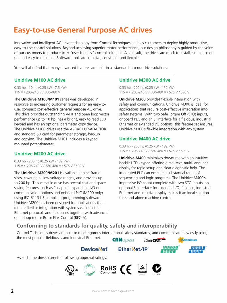
Conforming to standards for quality, safety and interoperabilityControl Techniques drives are built to meet rigorous international safety standards, and communicate flawlessly using the most popular fieldbuses and industrial Ethernet.
As such, the drives carry the following approval ratings:
APPR OVA
L
IS
O 9002
APPR OVA
L
IS
O 9002
APPR OVA
L
IS
O 9002
APPROVAL
ISO 9001 CAT
Ether®
Innovative and intelligent AC drive technology from Control Techniques enables customers to deploy highly productive, easy-to-use control solutions. Beyond achieving superior motor performance, our design philosophy is guided by the voice of our customers to produce truly “user friendly” control solutions. As a result, the drives are quick to install, simple to set up, and easy to maintain. Software tools are intuitive, consistent and flexible.
You will also find that many advanced features are built-in as standard into our drive solutions.
Easy-to-use General Purpose AC drives
Unidrive M100 AC drive
0.33 hp - 10 hp (0.25 kW - 7.5 kW) 115 V / 208-240 V / 380-480 V
The Unidrive M100/M101 series was developed in response to increasing customer requests for an easy-to-use, compact cost-effective general purpose AC drive. This drive provides outstanding V/Hz and open loop vector performance up to 10 hp, has a bright, easy to read LED keypad and has an optional parameter copy device. The Unidrive M100 drives use the AI-BACKUP-ADAPTOR and standard SD card for parameter storage, backup and copying. The Unidrive M101 includes a keypad mounted potentiometer.
Unidrive M200 AC drive
0.33 hp - 200 hp (0.25 kW - 132 kW) 115 V / 208-240 V / 380-480 V / 575 V / 690 V
The Unidrive M200/M201 is available in nine frame sizes, covering all low voltage ranges, and provides up to 200 hp. This versatile drive has several cost and space saving features, such as “snap in” expandable I/O or communication options and onboard PLC (M200 only) using IEC-61131-3 compliant programming software. Unidrive M200 has been designed for applications that require flexible integration with systems via industrial Ethernet protocols and fieldbuses together with advanced open-loop motor Rotor Flux Control (RFC-A).
Unidrive M300 AC drive
0.33 hp - 200 hp (0.25 kW - 132 kW) 115 V / 208-240 V / 380-480 V / 575 V / 690 V
Unidrive M300 provides flexible integration with safety and communications. Unidrive M300 is ideal for applications that require cost-effective integration into safety systems. With two Safe Torque Off (STO) inputs, onboard PLC and an SI interface for a fieldbus, industrial Ethernet or extended I/O options, this feature set ensures Unidrive M300’s flexible integration with any system.
Unidrive M400 AC drive
0.33 hp - 200 hp (0.25 kW - 132 kW) 115 V / 208-240 V / 380-480 V / 575 V / 690 V
Unidrive M400 minimizes downtime with an intuitive backlit LCD keypad offering a real-text, multi-language display for rapid setup and clear diagnostic help. The integrated PLC can execute a substantial range of sequencing and logic programs. The Unidrive M400’s impressive I/O count complete with two STO inputs, an optional SI interface for extended I/O, fieldbus, industrial Ethernet and intuitive display makes it an ideal solution for stand-alone machine control.
3www.controltechniques.com
No specialist knowledge required
Designed to make setup as simple as possible. In fact, many applications require changing just a few settings. Adjustments are easy with the keypad and clear referencing guide.
Fast setup
For fast batch production, parameters can be transferred onto new drives using standard SD cards. You’ll need either the optional AI-BACKUP-MODULE or AI-SMART-ADAPTOR and 24 Vdc power.
Visit www.Drive-Setup.com for step by step guides, videos, software & product support documentation.
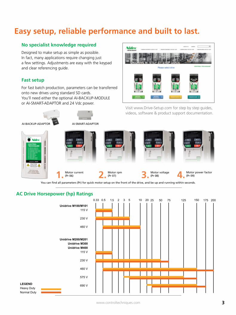
Unidrive M100/M101115 V
230 V
460 V
Unidrive M200/M201Unidrive M300Unidrive M400
115 V
230 V
460 V
575 V
690 V
7525 50 125 150 175 200AC Drive Horsepower (hp) Ratings
LEGENDHeavy DutyNormal Duty
AC Drive Horsepower (hp) Ratings
Motor current (Pr 06)
Motor rpm (Pr 07)
Motor voltage (Pr 08)
Motor power factor(Pr 09)
You can find all parameters (Pr) for quick motor setup on the front of the drive, and be up and running within seconds.
1. 2. 3. 4.
AI-BACKUP-ADAPTOR AI-SMART-ADAPTOR
Easy setup, reliable performance and built to last.
4 www.controltechniques.com
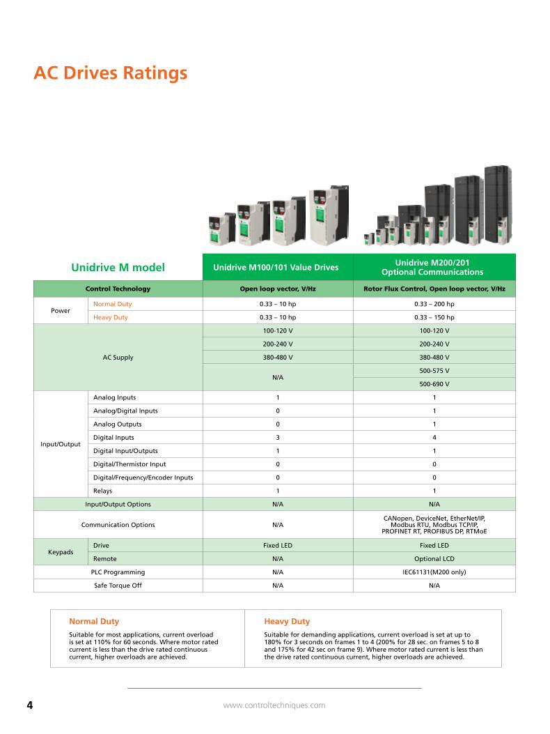
Unidrive M model Unidrive M100/101 Value Drives Unidrive M200/201 Optional Communications
Control Technology Open loop vector, V/Hz Rotor Flux Control, Open loop vector, V/Hz
PowerNormal Duty 0.33 – 10 hp 0.33 – 200 hp
Heavy Duty 0.33 – 10 hp 0.33 – 150 hp
AC Supply
100-120 V 100-120 V
200-240 V 200-240 V
380-480 V 380-480 V
N/A500-575 V
500-690 V
Input/Output
Analog Inputs 1 1
Analog/Digital Inputs 0 1
Analog Outputs 0 1
Digital Inputs 3 4
Digital Input/Outputs 1 1
Digital/Thermistor Input 0 0
Digital/Frequency/Encoder Inputs 0 0
Relays 1 1
Input/Output Options N/A N/A
Communication Options N/ACANopen, DeviceNet, EtherNet/IP,
Modbus RTU, Modbus TCP/IP, PROFINET RT, PROFIBUS DP, RTMoE
KeypadsDrive Fixed LED Fixed LED
Remote N/A Optional LCD
PLC Programming N/A IEC61131(M200 only)
Safe Torque Off N/A N/A
Normal Duty
Suitable for most applications, current overload is set at 110% for 60 seconds. Where motor rated current is less than the drive rated continuous current, higher overloads are achieved.
Heavy Duty
Suitable for demanding applications, current overload is set at up to 180% for 3 seconds on frames 1 to 4 (200% for 28 sec. on frames 5 to 8 and 175% for 42 sec on frame 9). Where motor rated current is less than the drive rated continuous current, higher overloads are achieved.
AC Drives Ratings
5www.controltechniques.com
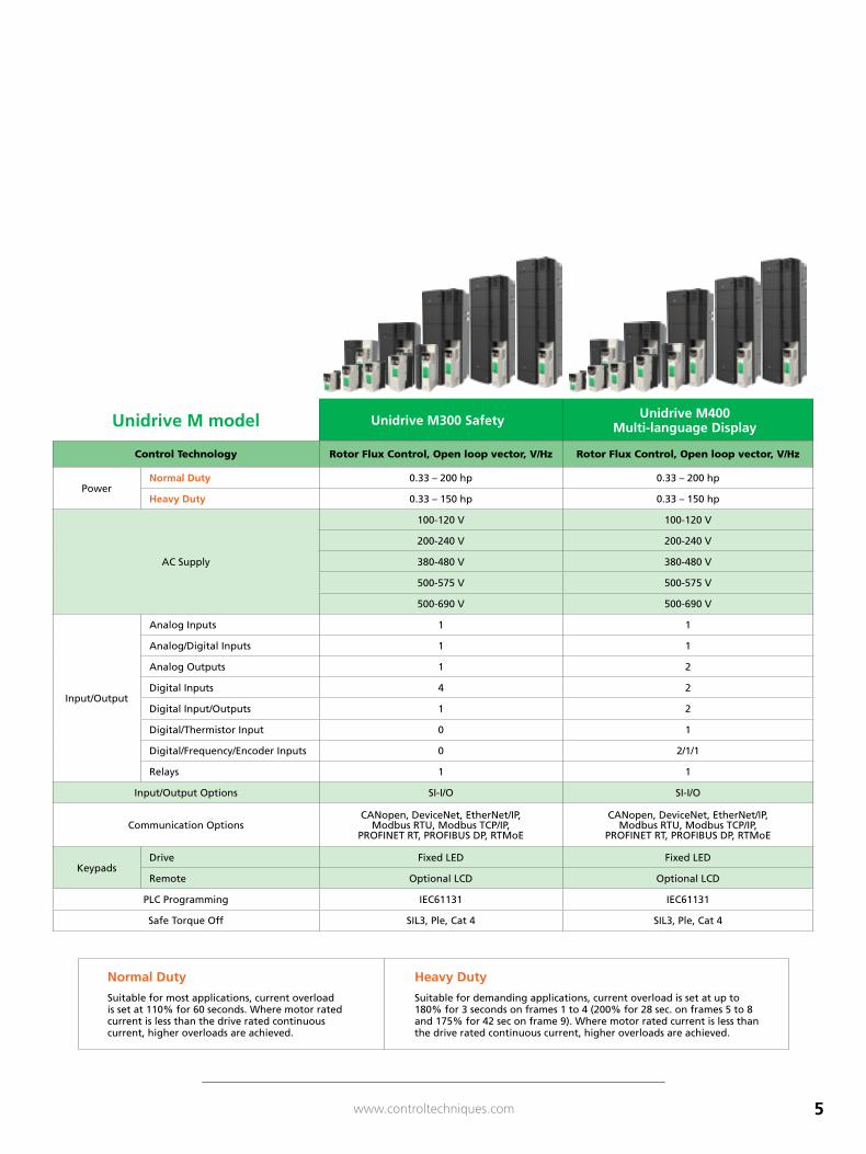
Unidrive M model Unidrive M300 Safety Unidrive M400 Multi-language Display
Control Technology Rotor Flux Control, Open loop vector, V/Hz Rotor Flux Control, Open loop vector, V/Hz
PowerNormal Duty 0.33 – 200 hp 0.33 – 200 hp
Heavy Duty 0.33 – 150 hp 0.33 – 150 hp
AC Supply
100-120 V 100-120 V
200-240 V 200-240 V
380-480 V 380-480 V
500-575 V 500-575 V
500-690 V 500-690 V
Input/Output
Analog Inputs 1 1
Analog/Digital Inputs 1 1
Analog Outputs 1 2
Digital Inputs 4 2
Digital Input/Outputs 1 2
Digital/Thermistor Input 0 1
Digital/Frequency/Encoder Inputs 0 2/1/1
Relays 1 1
Input/Output Options SI-I/O SI-I/O
Communication OptionsCANopen, DeviceNet, EtherNet/IP,
Modbus RTU, Modbus TCP/IP, PROFINET RT, PROFIBUS DP, RTMoE
CANopen, DeviceNet, EtherNet/IP, Modbus RTU, Modbus TCP/IP,
PROFINET RT, PROFIBUS DP, RTMoE
KeypadsDrive Fixed LED Fixed LED
Remote Optional LCD Optional LCD
PLC Programming IEC61131 IEC61131
Safe Torque Off SIL3, Ple, Cat 4 SIL3, Ple, Cat 4
Normal Duty
Suitable for most applications, current overload is set at 110% for 60 seconds. Where motor rated current is less than the drive rated continuous current, higher overloads are achieved.
Heavy Duty
Suitable for demanding applications, current overload is set at up to 180% for 3 seconds on frames 1 to 4 (200% for 28 sec. on frames 5 to 8 and 175% for 42 sec on frame 9). Where motor rated current is less than the drive rated continuous current, higher overloads are achieved.
6 www.controltechniques.com
APPROVAL
ISO 9001
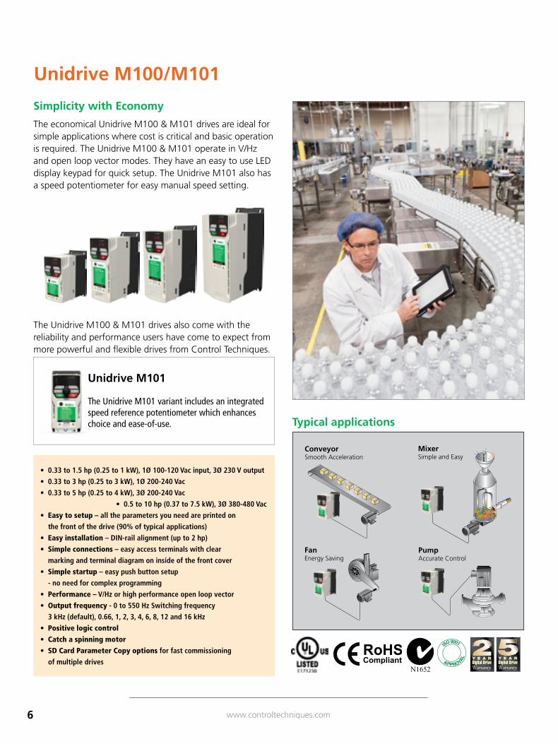
Simplicity with Economy
The economical Unidrive M100 & M101 drives are ideal for simple applications where cost is critical and basic operation is required. The Unidrive M100 & M101 operate in V/Hz and open loop vector modes. They have an easy to use LED display keypad for quick setup. The Unidrive M101 also has a speed potentiometer for easy manual speed setting.
The Unidrive M100 & M101 drives also come with the reliability and performance users have come to expect from more powerful and flexible drives from Control Techniques.
Unidrive M100/M101
Typical applications
Unidrive M101
The Unidrive M101 variant includes an integrated speed reference potentiometer which enhances choice and ease-of-use.
• 0.33 to 1.5 hp (0.25 to 1 kW), 1Ø 100-120 Vac input, 3Ø 230 V output
• 0.33 to 3 hp (0.25 to 3 kW), 1Ø 200-240 Vac
• 0.33 to 5 hp (0.25 to 4 kW), 3Ø 200-240 Vac
• 0.5 to 10 hp (0.37 to 7.5 kW), 3Ø 380-480 Vac
• Easy to setup – all the parameters you need are printed on
the front of the drive (90% of typical applications)
• Easy installation – DIN-rail alignment (up to 2 hp)
• Simple connections – easy access terminals with clear
marking and terminal diagram on inside of the front cover
• Simple startup – easy push button setup
- no need for complex programming
• Performance – V/Hz or high performance open loop vector
• Output frequency - 0 to 550 Hz Switching frequency
3 kHz (default), 0.66, 1, 2, 3, 4, 6, 8, 12 and 16 kHz
• Positive logic control
• Catch a spinning motor
• SD Card Parameter Copy options for fast commissioning
of multiple drives
PumpAccurate Control
FanEnergy Saving
ConveyorSmooth Acceleration
MixerSimple and Easy

7www.controltechniques.com
100 / 120 VAC ±10%
Base Order Code
M10x- ➂Size
Motor Power Input
Phase
Continuous Output
Current (A)
Overload Current
(A) hp kW
01100017A 1 0.33 0.25 1 1.7 2.6
01100024A 1 0.5 0.37 1 2.4 3.6
02100042A 2 1 0.75 1 4.2 6.3
02100056A 2 1.5 1.1 1 5.6 8.4
200 / 240 VAC ±10%
Base Order Code
M10x- ➂Size
Motor Power Input
Phase
Continuous Output
Current (A)
Overload Current
(A) hp kW
01200017A 1 0.33 0.25 1 1.7 2.6
01200024A 1 0.5 0.37 1 2.4 3.6
01200033A 1 0.75 0.55 1 3.3 5
01200042A 1 1 0.75 1 4.2 6.3
02200024A 2 0.5 0.37 1/3 2.4 3.6
02200033A 2 0.75 0.55 1/3 3.3 5
02200042A 2 1 0.75 1/3 4.2 6.3
02200056A 2 1.5 1.1 1/3 5.6 8.4
02200075A 2 2 1.5 1/3 7.5 11.3
03200100A 3 3 2.2 1/3 10 15
04200133A 4 3 3.0 1/3 13.3 20
04200176A 4 5 4.0 3 17.6 26.4
380 / 480 VAC ±10%
Base Order Code
M10x- ➂Size
Motor Power Input
Phase
Continuous Output
Current (A)
Overload Current
(A) hp kW
02400013A 2 0.5 0.37 3 1.3 2
02400018A 2 0.75 0.55 3 1.8 2.7
02400023A 2 1 0.75 3 2.3 3.5
02400032A 2 1.5 1.1 3 3.2 4.8
02400041A 2 2 1.5 3 4.1 6.2
03400056A 3 3 2.2 3 5.6 8.4
03400073A 3 3 3 3 7.3 11
03400094A 3 5 4.0 3 9.4 14.1
04400135A 4 7.5 5.5 3 13.5 20.3
04400170A 4 10 7.5 3 17 25.5
UNIDRIVE M100/M101 RATINGS
Motor horsepower based on typical 4-pole motor ratings. hp ratings are based on typical 230 V motors for 110/120 V and 200/240 V drives and 460 V for 380/480 V drives. kW ratings are based on typical 220 V motors for 110/120 V and 200/240 V drives and 400 V for 380/480 V drives. Select model based on actual motor nameplate current rating. Overload: 150 % (for 60 s).
➂ Add 10101AB100 to the base order code when ordering standard US (60 Hz) default products.
FEATURE Performance Advantage
Unidrive M101 powers up in Keypad Mode Easy-to-use. Ready to run out of the box.
6 Operator Buttons: Enter, Escape, Up, Down, Stop/Reset and Start. Bright LED Display
Easy to program and use. Top Ten Level 1 Parameters Listed on the Drive’s Front Cover
On-the-spot easy reference for drive setup and maintenance.
Security LockEnables the user the ability to lock unwanted parameter edits with a security code.
Configurable Analog and Digital I/OCustomizes drive to the specific application. 3 configurable digital input terminals (defaults are: Enable, Run Forward, Run Reverse), 1 configurable digital input/output terminal (at zero frequency), 1 relay output (Drive OK) and 1 analog input (0-10 V or 0-20/4-20 mA).
Comprehensive Diagnostics8 display alarm codes, 68 trip codes and 10 trip history log.
Flexible Control Features
8 preset speeds, 7 stopping modes including DC injection braking. Catch a spinning motor algorithm.
Quadratic Motor V/Hz Control Optimizes multimotor fan and pump operation.
Dynamic Motor V/Hz Control Optimizes energy savings.
Open Loop Vector Control with True Space Vector Modulation
Precise control algorithm provides full torque down to 1 Hz for exceptional performance.
8 www.controltechniques.com
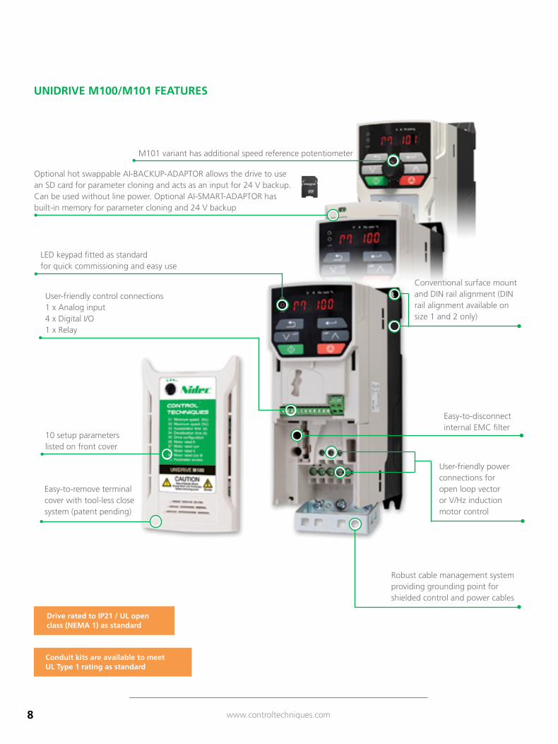
LED keypad fitted as standard for quick commissioning and easy use
M101 variant has additional speed reference potentiometer
Conventional surface mount and DIN rail alignment (DIN rail alignment available on size 1 and 2 only)
User-friendly control connections 1 x Analog input 4 x Digital I/O 1 x Relay
Robust cable management system providing grounding point for shielded control and power cables
User-friendly power connections for open loop vector or V/Hz induction motor control
Easy-to-disconnect internal EMC filter
Optional hot swappable AI-BACKUP-ADAPTOR allows the drive to use an SD card for parameter cloning and acts as an input for 24 V backup. Can be used without line power. Optional AI-SMART-ADAPTOR has built-in memory for parameter cloning and 24 V backup
Easy-to-remove terminal cover with tool-less close system (patent pending)
10 setup parameters listed on front cover
Drive rated to IP21 / UL open class (NEMA 1) as standard
Conduit kits are available to meet UL Type 1 rating as standard
UNIDRIVE M100/M101 FEATURES
9www.controltechniques.com
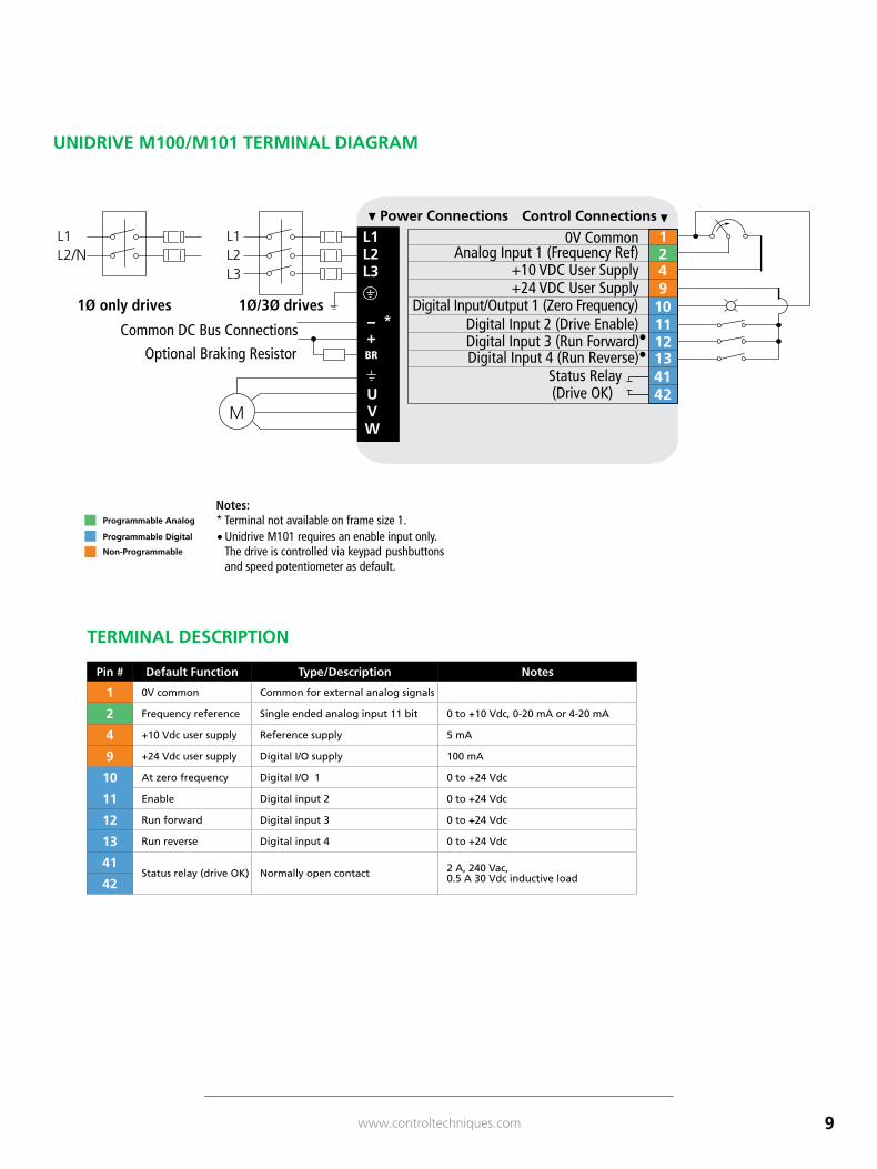
Notes:* Terminal not available on frame size 1.
Unidrive M101 requires an enable input only.The drive is controlled via keypad pushbuttonsand speed potentiometer as default.
•
Status Relay
Digital Input/Output 1 (Zero Frequency)+24 VDC User Supply
••
Digital Input 2 (Drive Enable)
Digital Input 4 (Run Reverse)Digital Input 3 (Run Forward)
Analog Input 1 (Frequency Ref)0V Common
+10 VDC User Supply
Control Connections
Common DC Bus Connections
Optional Braking Resistor
(Drive OK)
1Ø/3Ø drives1Ø only drives
/N
– *+BR
Pin # Default Function Type/Description Notes
1 0V common Common for external analog signals
2 Frequency reference Single ended analog input 11 bit 0 to +10 Vdc, 0-20 mA or 4-20 mA
4 +10 Vdc user supply Reference supply 5 mA
9 +24 Vdc user supply Digital I/O supply 100 mA
10 At zero frequency Digital I/O 1 0 to +24 Vdc
11 Enable Digital input 2 0 to +24 Vdc
12 Run forward Digital input 3 0 to +24 Vdc
13 Run reverse Digital input 4 0 to +24 Vdc
41Status relay (drive OK) Normally open contact 2 A, 240 Vac,
0.5 A 30 Vdc inductive load42
TERMINAL DESCRIPTION
Notes:* Terminal not available on frame size 1.
Unidrive M101 requires an enable input only.The drive is controlled via keypad pushbuttonsand speed potentiometer as default.
•
Status Relay
Digital Input/Output 1 (Zero Frequency)+24 VDC User Supply
••
Digital Input 2 (Drive Enable)
Digital Input 4 (Run Reverse)Digital Input 3 (Run Forward)
Analog Input 1 (Frequency Ref)0V Common
+10 VDC User Supply
Control Connections
Common DC Bus Connections
Optional Braking Resistor
(Drive OK)
1Ø/3Ø drives1Ø only drives
/N
– *+BR
UNIDRIVE M100/M101 TERMINAL DIAGRAM
10 www.controltechniques.com
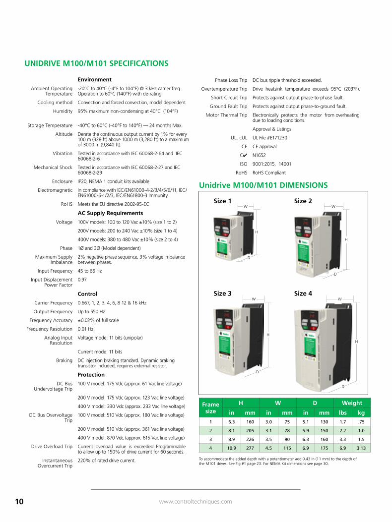
Frame size
H W D Weight
in mm in mm in mm lbs kg1 6.3 160 3.0 75 5.1 130 1.7 .75
2 8.1 205 3.1 78 5.9 150 2.2 1.0
3 8.9 226 3.5 90 6.3 160 3.3 1.5
4 10.9 277 4.5 115 6.9 175 6.9 3.13
W
H
D
W
H
D
W
H
D
W
H
D
Environment
Ambient Operating Temperature
-20°C to 40°C (-4°F to 104°F) @ 3 kHz carrier freq. Operation to 60°C (140°F) with de-rating
Cooling method Convection and forced convection, model dependent
Humidity 95% maximum non-condensing at 40°C (104°F)
Storage Temperature -40°C to 60°C (-40°F to 140°F) — 24 months Max.
Altitude Derate the continuous output current by 1% for every 100 m (328 ft) above 1000 m (3,280 ft) to a maximum of 3000 m (9,840 ft).
Vibration Tested in accordance with IEC 60068-2-64 and IEC 60068-2-6
Mechanical Shock Tested in accordance with IEC 60068-2-27 and IEC 60068-2-29
Enclosure IP20, NEMA 1 conduit kits available
Electromagnetic In compliance with IEC/EN61000-4-2/3/4/5/6/11, IEC/EN61000-6-1/2/3, IEC/EN61800-3 Immunity
RoHS Meets the EU directive 2002-95-EC
AC Supply Requirements
Voltage 100V models: 100 to 120 Vac ±10% (size 1 to 2)
200V models: 200 to 240 Vac ±10% (size 1 to 4)
400V models: 380 to 480 Vac ±10% (size 2 to 4)
Phase 1Ø and 3Ø (Model dependent)
Maximum Supply Imbalance
2% negative phase sequence, 3% voltage imbalance between phases.
Input Frequency 45 to 66 Hz
Input Displacement Power Factor
0.97
Control
Carrier Frequency 0.667, 1, 2, 3, 4, 6, 8 12 & 16 kHz
Output Frequency Up to 550 Hz
Frequency Accuracy ±0.02% of full scale
Frequency Resolution 0.01 Hz
Analog Input Resolution
Voltage mode: 11 bits (unipolar)
Current mode: 11 bits
Braking DC injection braking standard. Dynamic braking transistor included, requires external resistor.
Protection
DC Bus Undervoltage Trip
100 V model: 175 Vdc (approx. 61 Vac line voltage)
200 V model: 175 Vdc (approx. 123 Vac line voltage)
400 V model: 330 Vdc (approx. 233 Vac line voltage)
DC Bus Overvoltage Trip
100 V model: 510 Vdc (approx. 180 Vac line voltage)
200 V model: 510 Vdc (approx. 361 Vac line voltage)
400 V model: 870 Vdc (approx. 615 Vac line voltage)
Drive Overload Trip Current overload value is exceeded. Programmable to allow up to 150% of drive current for 60 seconds.
Instantaneous Overcurrent Trip
220% of rated drive current.
Phase Loss Trip DC bus ripple threshold exceeded.
Overtemperature Trip Drive heatsink temperature exceeds 95°C (203°F).
Short Circuit Trip Protects against output phase-to-phase fault.
Ground Fault Trip Protects against output phase-to-ground fault.
Motor Thermal Trip Electronically protects the motor from overheating due to loading conditions.
Approval & Listings
UL, cUL UL File #E171230
CE CE approval
C✔ N1652
ISO 9001:2015, 14001
RoHS RoHS Compliant
To accommodate the added depth with a potentiometer add 0.43 in (11 mm) to the depth of the M101 drives. See Fig #1 page 23. For NEMA Kit dimensions see page 30.
UNIDRIVE M100/M101 SPECIFICATIONS
Unidrive M100/M101 DIMENSIONS
Size 2Size 1
Size 3 Size 4
11www.controltechniques.com
Option Description Order code
Drive Configuration
Parameter copying & 24 V backup; SD card required AI-BACKUP-ADAPTOR
8 GB SD Card CTSD8GB
Parameter copying & 24 V backup; 4 GB SD card included AI-SMART-ADAPTOR
Power Accessories
EMC Filters
See Unidrive M Accessories
Line & Load Reactors
Dynamic Braking Resistors
Environmental Protection
& Cable Management
NEMA 1 / UL Type 1 Conduit Box Kits
See Unidrive M AccessoriesRetrofit Kits for Commander
SK replacement
Fan Replacement Kits
Frame size Order code3 3470-0097
4 3470-0101
Frame size Order code1 3470-0092
2 3470-0095
3 3470-0099
4 3470-0103
Frame size
Order code
H W D
in mm in mm in mm
1 C-BOX-OF1 9.9 252 3.0 75 5.1 130
2 C-BOX-OF2 11.6 294 3.0 75 5.9 150
3 C-BOX-OF3 12.4 314 3.5 90 6.3 160
4 C-BOX-OF4 14.3 362 4.5 115 6.9 175
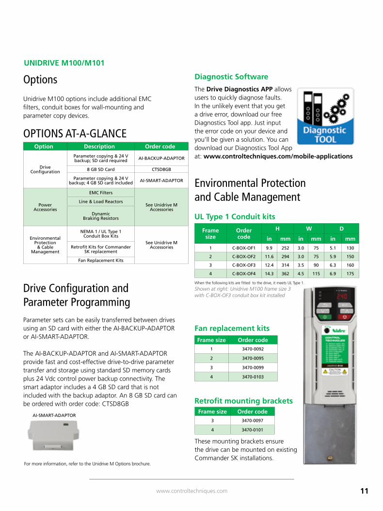
UNIDRIVE M100/M101
Options
Unidrive M100 options include additional EMC filters, conduit boxes for wall-mounting and parameter copy devices.
Drive Configuration and Parameter ProgrammingParameter sets can be easily transferred between drives using an SD card with either the AI-BACKUP-ADAPTOR or AI-SMART-ADAPTOR.
The AI-BACKUP-ADAPTOR and AI-SMART-ADAPTOR provide fast and cost-effective drive-to-drive parameter transfer and storage using standard SD memory cards plus 24 Vdc control power backup connectivity. The smart adaptor includes a 4 GB SD card that is not included with the backup adaptor. An 8 GB SD card can be ordered with order code: CTSD8GB
For more information, refer to the Unidrive M Options brochure.
AI-SMART-ADAPTOR
Fan replacement kits
Retrofit mounting brackets
These mounting brackets ensure the drive can be mounted on existing Commander SK installations.
UL Type 1 Conduit kits
When the following kits are fitted to the drive, it meets UL Type 1.
Shown at right: Unidrive M100 frame size 3 with C-BOX-OF3 conduit box kit installed
Environmental Protection and Cable Management
Diagnostic Software
The Drive Diagnostics APP allows users to quickly diagnose faults. In the unlikely event that you get a drive error, download our free Diagnostics Tool app. Just input the error code on your device and you’ll be given a solution. You can download our Diagnostics Tool App at: www.controltechniques.com/mobile-applications
OPTIONS AT-A-GLANCE
12 www.controltechniques.com
APPROVAL
ISO 9001
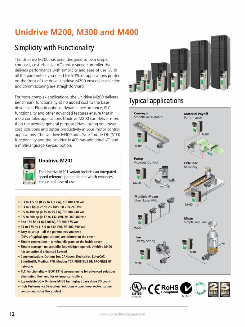
Simplicity with Functionality The Unidrive M200 has been designed to be a simple, compact, cost-effective AC motor speed controller that delivers performance with simplicity and ease of use. With all the parameters you need for 90% of applications printed on the front of the drive, Unidrive M200 ensures installation and commissioning are straightforward.
For more complex applications, the Unidrive M200 delivers benchmark functionality at no added cost to the base drive itself. Plug-in options, dynamic performance, PLC functionality and other advanced features ensure that in more complex applications Unidrive M200 can deliver more than the average general purpose drive - giving you lower cost solutions and better productivity in your motor control applications. The Unidrive M300 adds Safe Torque Off (STO) functionality and the Unidrive M400 has additional I/O and a multi-language keypad option.
Unidrive M200, M300 and M400
Typical applications
• 0.3 to 1.5 hp (0.75 to 1.1 kW), 1Ø 100-120 Vac
• 0.3 to 3 hp (0.25 to 2.2 kW), 1Ø 200-240 Vac
• 0.5 to 100 hp (0.75 to 75 kW), 3Ø 200-240 Vac
• 0.5 to 200 hp (0.37 to 132 kW), 3Ø 380-480 Vac
• 3 to 150 hp (3 to 110kW), 3Ø 500-575 Vac
• 25 to 175 hp (18.5 to 132 kW), 3Ø 500-690 Vac
• Easy to setup – all the parameters you need
(90% of typical applications) are printed on the cover
• Simple connections – terminal diagram on the inside cover
• Simple startup – no specialist knowledge required, Unidrive M400
has an optional enhanced keypad
• Communications Options for: CANopen, DeviceNet, EtherCAT,
EtherNet/IP, Modbus RTU, Modbus TCP, PROFIBUS DP, PROFINET RT
networks
• PLC Functionality – IEC61131-3 programming for advanced solutions
eliminating the need for external controllers
• Expandable I/O – Unidrive M400 has highest base drive I/O count
• High Performance Sensorless Solutions – open loop vector, torque
control and rotor flux control
ConveyorSmooth Acceleration
Material PayoffPerformance
PumpAccurate Control
M200
M300
FanEnergy Saving
M200
Multiple MotorOpen Loop V/Hz
M200
ExtruderReliability
M400
MixerSimple and Easy
M400
M300
Unidrive M201
The Unidrive M201 variant includes an integrated speed reference potentiometer which enhances choice and ease-of-use.
13www.controltechniques.com
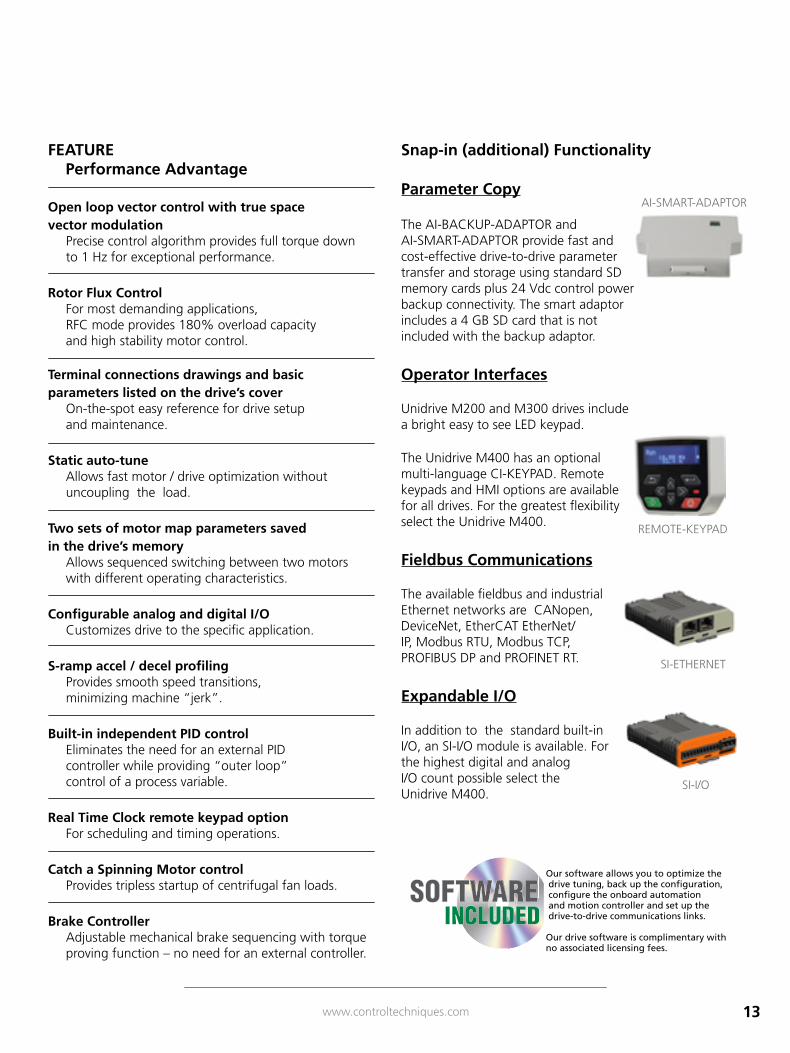
Snap-in (additional) Functionality
Parameter Copy
The AI-BACKUP-ADAPTOR and AI-SMART-ADAPTOR provide fast and cost-effective drive-to-drive parameter transfer and storage using standard SD memory cards plus 24 Vdc control power backup connectivity. The smart adaptor includes a 4 GB SD card that is not included with the backup adaptor.
Operator Interfaces
Unidrive M200 and M300 drives include a bright easy to see LED keypad.
The Unidrive M400 has an optional multi-language CI-KEYPAD. Remote keypads and HMI options are available for all drives. For the greatest flexibility select the Unidrive M400.
Fieldbus Communications
The available fieldbus and industrial Ethernet networks are CANopen, DeviceNet, EtherCAT EtherNet/IP, Modbus RTU, Modbus TCP, PROFIBUS DP and PROFINET RT.
Expandable I/O
In addition to the standard built-in I/O, an SI-I/O module is available. For the highest digital and analog I/O count possible select the Unidrive M400.
SI-I/O
SI-ETHERNET
AI-SMART-ADAPTOR
REMOTE-KEYPAD
FEATURE Performance Advantage
Open loop vector control with true space vector modulation
Precise control algorithm provides full torque down to 1 Hz for exceptional performance.
Rotor Flux Control
For most demanding applications, RFC mode provides 180% overload capacity and high stability motor control.
Terminal connections drawings and basic parameters listed on the drive’s cover
On-the-spot easy reference for drive setup and maintenance.
Static auto-tuneAllows fast motor / drive optimization without uncoupling the load.
Two sets of motor map parameters saved in the drive’s memory
Allows sequenced switching between two motors with different operating characteristics.
Configurable analog and digital I/OCustomizes drive to the specific application.
S-ramp accel / decel profilingProvides smooth speed transitions, minimizing machine “jerk”.
Built-in independent PID control Eliminates the need for an external PID controller while providing “outer loop” control of a process variable.
Real Time Clock remote keypad option For scheduling and timing operations.
Catch a Spinning Motor control Provides tripless startup of centrifugal fan loads.
Brake Controller Adjustable mechanical brake sequencing with torque proving function – no need for an external controller.
Our software allows you to optimize the drive tuning, back up the configuration, configure the onboard automation and motion controller and set up the drive-to-drive communications links.
Our drive software is complimentary with no associated licensing fees.
SOFTWAREINCLUDED
14 www.controltechniques.com
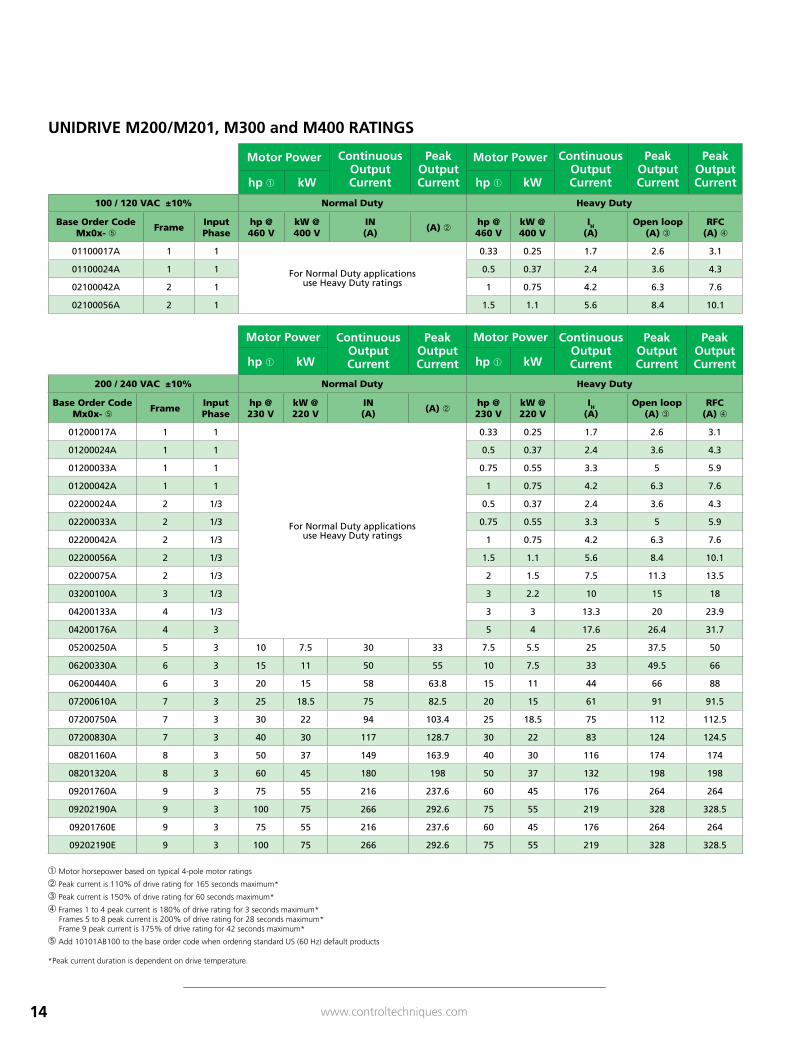
Motor Power Continuous Output Current
Peak Output Current
Motor Power Continuous Output Current
Peak Output Current
Peak Output Currenthp kW hp kW
100 / 120 VAC ±10% Normal Duty Heavy Duty
Base Order Code Mx0x- ➄ Frame Input
Phasehp @ 460 V
kW @ 400 V
IN (A) (A)
hp @ 460 V
kW @ 400 V
IH (A)
Open loop (A) ➂
RFC (A) ➃
01100017A 1 1
For Normal Duty applications use Heavy Duty ratings
0.33 0.25 1.7 2.6 3.1
01100024A 1 1 0.5 0.37 2.4 3.6 4.3
02100042A 2 1 1 0.75 4.2 6.3 7.6
02100056A 2 1 1.5 1.1 5.6 8.4 10.1
Motor Power Continuous Output Current
Peak Output Current
Motor Power Continuous Output Current
Peak Output Current
Peak Output Currenthp kW hp kW
200 / 240 VAC ±10% Normal Duty Heavy Duty
Base Order Code Mx0x- ➄ Frame Input
Phasehp @ 230 V
kW @ 220 V
IN (A) (A)
hp @ 230 V
kW @ 220 V
IH (A)
Open loop (A) ➂
RFC (A) ➃
01200017A 1 1
For Normal Duty applications use Heavy Duty ratings
0.33 0.25 1.7 2.6 3.1
01200024A 1 1 0.5 0.37 2.4 3.6 4.3
01200033A 1 1 0.75 0.55 3.3 5 5.9
01200042A 1 1 1 0.75 4.2 6.3 7.6
02200024A 2 1/3 0.5 0.37 2.4 3.6 4.3
02200033A 2 1/3 0.75 0.55 3.3 5 5.9
02200042A 2 1/3 1 0.75 4.2 6.3 7.6
02200056A 2 1/3 1.5 1.1 5.6 8.4 10.1
02200075A 2 1/3 2 1.5 7.5 11.3 13.5
03200100A 3 1/3 3 2.2 10 15 18
04200133A 4 1/3 3 3 13.3 20 23.9
04200176A 4 3 5 4 17.6 26.4 31.7
05200250A 5 3 10 7.5 30 33 7.5 5.5 25 37.5 50
06200330A 6 3 15 11 50 55 10 7.5 33 49.5 66
06200440A 6 3 20 15 58 63.8 15 11 44 66 88
07200610A 7 3 25 18.5 75 82.5 20 15 61 91 91.5
07200750A 7 3 30 22 94 103.4 25 18.5 75 112 112.5
07200830A 7 3 40 30 117 128.7 30 22 83 124 124.5
08201160A 8 3 50 37 149 163.9 40 30 116 174 174
08201320A 8 3 60 45 180 198 50 37 132 198 198
09201760A 9 3 75 55 216 237.6 60 45 176 264 264
09202190A 9 3 100 75 266 292.6 75 55 219 328 328.5
09201760E 9 3 75 55 216 237.6 60 45 176 264 264
09202190E 9 3 100 75 266 292.6 75 55 219 328 328.5
UNIDRIVE M200/M201, M300 and M400 RATINGS
Motor horsepower based on typical 4-pole motor ratings
Peak current is 110% of drive rating for 165 seconds maximum*
➂ Peak current is 150% of drive rating for 60 seconds maximum*
➃ Frames 1 to 4 peak current is 180% of drive rating for 3 seconds maximum* Frames 5 to 8 peak current is 200% of drive rating for 28 seconds maximum* Frame 9 peak current is 175% of drive rating for 42 seconds maximum*
➄ Add 10101AB100 to the base order code when ordering standard US (60 Hz) default products
*Peak current duration is dependent on drive temperature.
15www.controltechniques.com
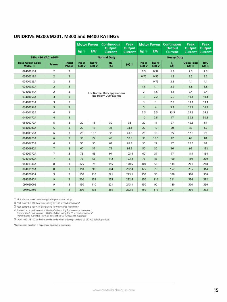
Motor Power Continuous Output Current
Peak Output Current
Motor Power Continuous Output Current
Peak Output Current
Peak Output Currenthp kW hp kW
380 / 480 VAC ±10% Normal Duty Heavy Duty
Base Order Code Mx0x- ➄ Frame Input
Phasehp @ 460 V
kW @ 400 V
IN (A) (A)
hp @ 460 V
kW @ 400 V
IH (A)
Open loop (A) ➂
RFC (A) ➃
02400013A 2 3
For Normal Duty applications use Heavy Duty ratings
0.5 0.37 1.3 2.3 2.3
02400018A 2 3 0.75 0.55 1.8 3.2 3.2
02400023A 2 3 1 0.75 2.3 4.1 4.1
02400032A 2 3 1.5 1.1 3.2 5.8 5.8
02400041A 2 3 2 1.5 4.1 7.4 7.4
03400056A 3 3 3 2.2 5.6 10.1 10.1
03400073A 3 3 3 3 7.3 13.1 13.1
03400094A 3 3 5 4 9.4 16.9 16.9
04400135A 4 3 7.5 5.5 13.5 24.3 24.3
04400170A 4 3 10 7.5 17 30.6 30.6
05400270A 5 3 20 15 30 33 20 11 27 40.5 54
05400300A 5 3 20 15 31 34.1 20 15 30 45 60
06400350A 6 3 25 18.5 38 41.8 25 15 35 52.5 70
06400420A 6 3 30 22 48 52.8 30 18.5 42 63 84
06400470A 6 3 50 30 63 69.3 30 22 47 70.5 94
07400660A 7 3 60 37 79 86.9 50 30 66 99 132
07400770A 7 3 75 45 94 103.4 60 37 77 115 154
07401000A 7 3 75 55 112 123.2 75 45 100 150 200
08401340A 8 3 125 75 155 170.5 100 55 134 201 268
08401570A 8 3 150 90 184 202.4 125 75 157 235 314
09402000A 9 3 150 110 221 243.1 150 90 180 300 350
09402240A 9 3 200 132 255 292.6 150 110 211 336 392
09402000E 9 3 150 110 221 243.1 150 90 180 300 350
09402240E 9 3 200 132 255 292.6 150 110 211 336 392
UNIDRIVE M200/M201, M300 and M400 RATINGS
Motor horsepower based on typical 4-pole motor ratings
Peak current is 110% of drive rating for 165 seconds maximum*
➂ Peak current is 150% of drive rating for 60 seconds maximum*
➃ Frames 1 to 4 peak current is 180% of drive rating for 3 seconds maximum* Frames 5 to 8 peak current is 200% of drive rating for 28 seconds maximum* Frame 9 peak current is 175% of drive rating for 42 seconds maximum*
➄ Add 10101AB100 to the base order code when ordering standard US (60 Hz) default products
*Peak current duration is dependent on drive temperature.
16 www.controltechniques.com
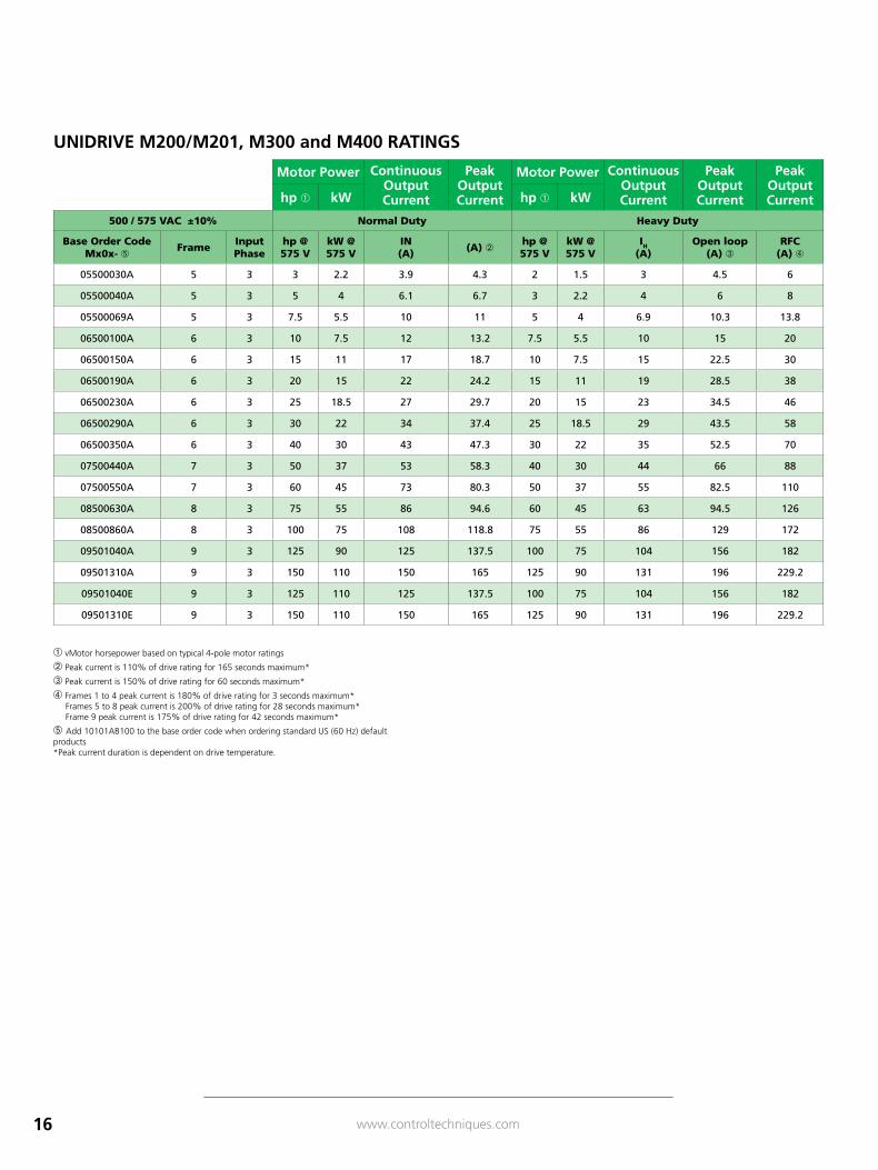
Motor Power Continuous Output Current
Peak Output Current
Motor Power Continuous Output Current
Peak Output Current
Peak Output Currenthp kW hp kW
500 / 575 VAC ±10% Normal Duty Heavy Duty
Base Order Code Mx0x- ➄ Frame Input
Phasehp @ 575 V
kW @ 575 V
IN (A) (A)
hp @ 575 V
kW @ 575 V
IH (A)
Open loop (A) ➂
RFC (A) ➃
05500030A 5 3 3 2.2 3.9 4.3 2 1.5 3 4.5 6
05500040A 5 3 5 4 6.1 6.7 3 2.2 4 6 8
05500069A 5 3 7.5 5.5 10 11 5 4 6.9 10.3 13.8
06500100A 6 3 10 7.5 12 13.2 7.5 5.5 10 15 20
06500150A 6 3 15 11 17 18.7 10 7.5 15 22.5 30
06500190A 6 3 20 15 22 24.2 15 11 19 28.5 38
06500230A 6 3 25 18.5 27 29.7 20 15 23 34.5 46
06500290A 6 3 30 22 34 37.4 25 18.5 29 43.5 58
06500350A 6 3 40 30 43 47.3 30 22 35 52.5 70
07500440A 7 3 50 37 53 58.3 40 30 44 66 88
07500550A 7 3 60 45 73 80.3 50 37 55 82.5 110
08500630A 8 3 75 55 86 94.6 60 45 63 94.5 126
08500860A 8 3 100 75 108 118.8 75 55 86 129 172
09501040A 9 3 125 90 125 137.5 100 75 104 156 182
09501310A 9 3 150 110 150 165 125 90 131 196 229.2
09501040E 9 3 125 110 125 137.5 100 75 104 156 182
09501310E 9 3 150 110 150 165 125 90 131 196 229.2
UNIDRIVE M200/M201, M300 and M400 RATINGS
vMotor horsepower based on typical 4-pole motor ratings
Peak current is 110% of drive rating for 165 seconds maximum*
➂ Peak current is 150% of drive rating for 60 seconds maximum*
➃ Frames 1 to 4 peak current is 180% of drive rating for 3 seconds maximum* Frames 5 to 8 peak current is 200% of drive rating for 28 seconds maximum* Frame 9 peak current is 175% of drive rating for 42 seconds maximum*
➄ Add 10101AB100 to the base order code when ordering standard US (60 Hz) default products*Peak current duration is dependent on drive temperature.
17www.controltechniques.com
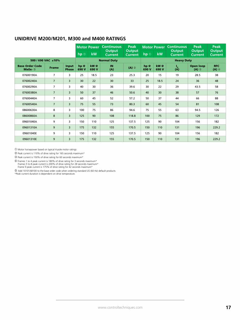
Motor Power Continuous Output Current
Peak Output Current
Motor Power Continuous Output Current
Peak Output Current
Peak Output Currenthp kW hp kW
500 / 690 VAC ±10% Normal Duty Heavy Duty
Base Order Code Mx0x- ➄ Frame Input
Phasehp @ 690 V
kW @ 690 V
IN (A) (A)
hp @ 690 V
kW @ 690 V
IH (A)
Open loop (A) ➂
RFC (A) ➃
07600190A 7 3 25 18.5 23 25.3 20 15 19 28.5 38
07600240A 7 3 30 22 30 33 25 18.5 24 36 48
07600290A 7 3 40 30 36 39.6 30 22 29 43.5 58
07600380A 7 3 50 37 46 50.6 40 30 38 57 76
07600440A 7 3 60 45 52 57.2 50 37 44 66 88
07600540A 7 3 75 55 73 80.3 60 45 54 81 108
08600630A 8 3 100 75 86 94.6 75 55 63 94.5 126
08600860A 8 3 125 90 108 118.8 100 75 86 129 172
09601040A 9 3 150 110 125 137.5 125 90 104 156 182
09601310A 9 3 175 132 155 170.5 150 110 131 196 229.2
09601040E 9 3 150 110 125 137.5 125 90 104 156 182
09601310E 9 3 175 132 155 170.5 150 110 131 196 229.2
UNIDRIVE M200/M201, M300 and M400 RATINGS
Motor horsepower based on typical 4-pole motor ratings
Peak current is 110% of drive rating for 165 seconds maximum*
➂ Peak current is 150% of drive rating for 60 seconds maximum*
➃ Frames 1 to 4 peak current is 180% of drive rating for 3 seconds maximum* Frames 5 to 8 peak current is 200% of drive rating for 28 seconds maximum* Frame 9 peak current is 175% of drive rating for 42 seconds maximum*
➄ Add 10101AB100 to the base order code when ordering standard US (60 Hz) default products*Peak current duration is dependent on drive temperature.
18 www.controltechniques.com
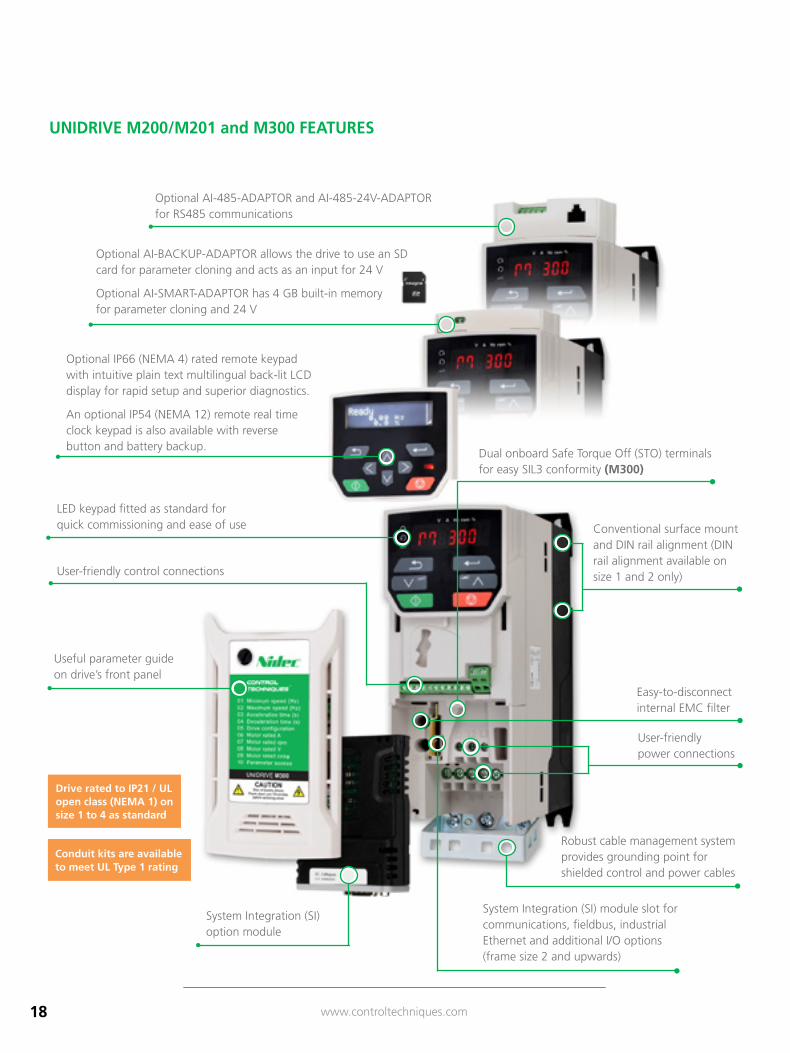
UNIDRIVE M200/M201 and M300 FEATURES
LED keypad fitted as standard for quick commissioning and ease of use
Optional IP66 (NEMA 4) rated remote keypad with intuitive plain text multilingual back-lit LCD display for rapid setup and superior diagnostics.
An optional IP54 (NEMA 12) remote real time clock keypad is also available with reverse button and battery backup.
User-friendly control connections
Robust cable management system provides grounding point for shielded control and power cables
User-friendly power connections
Easy-to-disconnect internal EMC filter
System Integration (SI) module slot for communications, fieldbus, industrial Ethernet and additional I/O options (frame size 2 and upwards)
Optional AI-BACKUP-ADAPTOR allows the drive to use an SD card for parameter cloning and acts as an input for 24 V
Optional AI-SMART-ADAPTOR has 4 GB built-in memory for parameter cloning and 24 V
Optional AI-485-ADAPTOR and AI-485-24V-ADAPTOR for RS485 communications
System Integration (SI) option module
Dual onboard Safe Torque Off (STO) terminals for easy SIL3 conformity (M300)
Drive rated to IP21 / UL open class (NEMA 1) on size 1 to 4 as standard
Conduit kits are available to meet UL Type 1 rating
Useful parameter guide on drive’s front panel
Conventional surface mount and DIN rail alignment (DIN rail alignment available on size 1 and 2 only)
19www.controltechniques.com
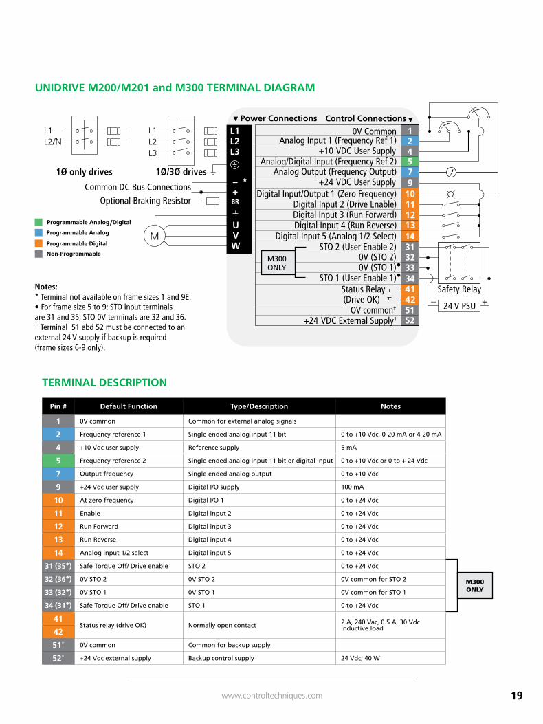
Safety Relay
24 V PSU +_
1Ø/3Ø drives1Ø only drives
/N
3433323114
75
– *+BR
5152
(Drive OK)Status Relay
0V (STO 2)STO 2 (User Enable 2)
•0V (STO 1)STO 1 (User Enable 1)•
Digital Input 5 (Analog 1/2 Select)Digital Input 4 (Run Reverse)Digital Input 3 (Run Forward) Digital Input 2 (Drive Enable)
Digital Input/Output 1 (Zero Frequency)+24 VDC User Supply
Analog Output (Frequency Output)Analog/Digital Input (Frequency Ref 2)
+10 VDC User SupplyAnalog Input 1 (Frequency Ref 1)
0V Common
Common DC Bus ConnectionsOptional Braking Resistor
Control Connections
OV common†
+24 VDC External Supply†
* Terminal not available on frame size 1.• For frame size 5 to 9: STO input terminalsare 31 and 35; STO 0V terminals are 32 and 36.
Notes:/
M300 ONLY
* Terminal not available on frame sizes 1 and 9E.• For frame size 5 to 9: STO input terminalsare 31 and 35; STO 0V terminals are 32 and 36.† Terminal 51 abd 52 must be connected to an external 24 V supply if backup is required (frame sizes 6-9 only).
Notes:
/
Pin # Default Function Type/Description Notes
1 0V common Common for external analog signals
2 Frequency reference 1 Single ended analog input 11 bit 0 to +10 Vdc, 0-20 mA or 4-20 mA
4 +10 Vdc user supply Reference supply 5 mA
5 Frequency reference 2 Single ended analog input 11 bit or digital input 0 to +10 Vdc or 0 to + 24 Vdc
7 Output frequency Single ended analog output 0 to +10 Vdc
9 +24 Vdc user supply Digital I/O supply 100 mA
10 At zero frequency Digital I/O 1 0 to +24 Vdc
11 Enable Digital input 2 0 to +24 Vdc
12 Run Forward Digital input 3 0 to +24 Vdc
13 Run Reverse Digital input 4 0 to +24 Vdc
14 Analog input 1/2 select Digital input 5 0 to +24 Vdc
31 (35•) Safe Torque Off/ Drive enable STO 2 0 to +24 Vdc
32 (36•) 0V STO 2 0V STO 2 0V common for STO 2
33 (32•) 0V STO 1 0V STO 1 0V common for STO 1
34 (31•) Safe Torque Off/ Drive enable STO 1 0 to +24 Vdc
41Status relay (drive OK) Normally open contact 2 A, 240 Vac, 0.5 A, 30 Vdc
inductive load42
51† 0V common Common for backup supply
52† +24 Vdc external supply Backup control supply 24 Vdc, 40 W
UNIDRIVE M200/M201 and M300 TERMINAL DIAGRAM
M300 ONLY
TERMINAL DESCRIPTION
20 www.controltechniques.com
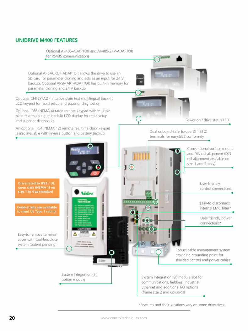
Optional AI-BACKUP-ADAPTOR allows the drive to use an SD card for parameter cloning and acts as an input for 24 V backup. Optional AI-SMART-ADAPTOR has built-in memory for parameter cloning and 24 V backup
UNIDRIVE M400 FEATURES
Optional CI-KEYPAD - intuitive plain text multilingual back-lit LCD keypad for rapid setup and superior diagnostics
Optional IP66 (NEMA 4) rated remote keypad with intuitive plain text multilingual back-lit LCD display for rapid setup and superior diagnostics
An optional IP54 (NEMA 12) remote real time clock keypad is also available with reverse button and battery backup Dual onboard Safe Torque Off (STO)
terminals for easy SIL3 conformity
User-friendly control connections
Easy-to-disconnect internal EMC filter*
Power-on / drive status LED
Drive rated to IP21 / UL open class (NEMA 1) on size 1 to 4 as standard
Conduit kits are available to meet UL Type 1 rating
Robust cable management system providing grounding point for shielded control and power cables
Easy-to-remove terminal cover with tool-less close system (patent pending)
*Features and their locations vary on some drive sizes.
Conventional surface mount and DIN rail alignment (DIN rail alignment available on size 1 and 2 only)
User-friendly power connections*
System Integration (SI) module slot for communications, fieldbus, industrial Ethernet and additional I/O options (frame size 2 and upwards)
Optional AI-485-ADAPTOR and AI-485-24V-ADAPTOR for RS485 communications
System Integration (SI) option module
21www.controltechniques.com
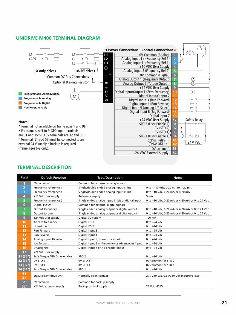
Safety Relay
24 V PSU +_
1Ø/3Ø drives1Ø only drives
/N
Common DC Bus Connections
Optional Braking Resistor
(Drive OK)Status Relay
0V (STO 2)STO 2 (User Enable 2)
•0V (STO 1)STO 1 (User Enable 1)•
+24 VDC User SupplyDigital Input 7
Digital Input 6 (Jog Forward)Digital Input 5 (Analog 1/2 Select)
Digital Input 4 (Run Reverse)Digital Input 3 (Run Forward)
Digital Input/Output 2Digital Input/Output 1 (Zero Frequency)
+24 VDC User SupplyAnalog Output 2 (Torque Output)
Analog Output 1 (Frequency Output)0V Common (Digital)
Analog Input 2 (Frequency Ref 2)+10 VDC User Supply
Analog Input 1- (Frequency Ref 1)Analog Input 1+ (Frequency Ref 1)
0V Common (Analog)Control Connections
3433323117161514
8765
3
– *+BR
• For frame size 5 to 9: STO input terminalsare 31 and 35; STO 0V terminals are 32 and 36.
* Terminal not available on frame size 1.Notes:
OV common†
+24 VDC External Supply†5152
• For frame size 5 to 9: STO input terminalsare 31 and 35; STO 0V terminals are 32 and 36.
* Terminal not available on frame size 1.Notes:
* Terminal not available on frame sizes 1 and 9E.• For frame size 5 to 9: STO input terminalsare 31 and 35; STO 0V terminals are 32 and 36.† Terminal 51 abd 52 must be connected to an external 24 V supply if backup is required (frame sizes 6-9 only).
Notes:
/
Pin # Default Function Type/Description Notes
1 0V common Common for external analog signals
2 Frequency reference 1 Single/double ended analog input 11 bit 0 to +/-10 Vdc, 0-20 mA or 4-20 mA
3 Frequency reference 1 Single/double ended analog input 11 bit 0 to +10 Vdc, 0-20 mA or 4-20 mA
4 +10 Vdc user supply Reference supply 5 mA
5 Frequency reference 2 Single ended analog input 11 bit or digital input 0 to +10 Vdc, 0-20 mA or 4-20 mA or 0 to 24 Vdc
6 Digital I/O 0V Common for external digital signals
7 Output frequency Single ended analog output or digital output 0 to +10 Vdc, 0-20 mA or 4-20 mA or 0 to 24 Vdc
8 Output torque Single ended analog output or digital output 0 to +10 Vdc, 0-20 mA or 4-20 mA or 0 to 24 Vdc
9 +24 Vdc user supply Digital I/O supply 100 mA
10 At zero frequency Digital I/O 1 0 to +24 Vdc
11 Unassigned Digital I/O 2 0 to +24 Vdc
12 Run Forward Digital input 3 0 to +24 Vdc
13 Run Reverse Digital input 4 0 to +24 Vdc
14 Analog input 1/2 select Digital input 5, thermistor input 0 to +24 Vdc
15 Jog forward Digital input 6 or Frequency or AB encoder input 0 to +24 Vdc
16 Unassigned Digital input 7 or AB encoder input 0 to +24 Vdc
17 +24 Vdc user supply
31 (35•) Safe Torque Off/ Drive enable STO 2 0 to +24 Vdc
32 (36•) 0V STO 2 0V STO 2 0V common for STO 2
33 (32•) 0V STO 1 0V STO 1 0V common for STO 1
34 (31•) Safe Torque Off/ Drive enable STO 1 0 to +24 Vdc
41Status relay (drive OK) Normally open contact 2 A, 240 Vac, 0.5 A, 30 Vdc inductive load
4251† 0V common Common for backup supply
52† +24 Vdc external supply Backup control supply 24 Vdc, 40 W
TERMINAL DESCRIPTION
UNIDRIVE M400 TERMINAL DIAGRAM
22 www.controltechniques.com
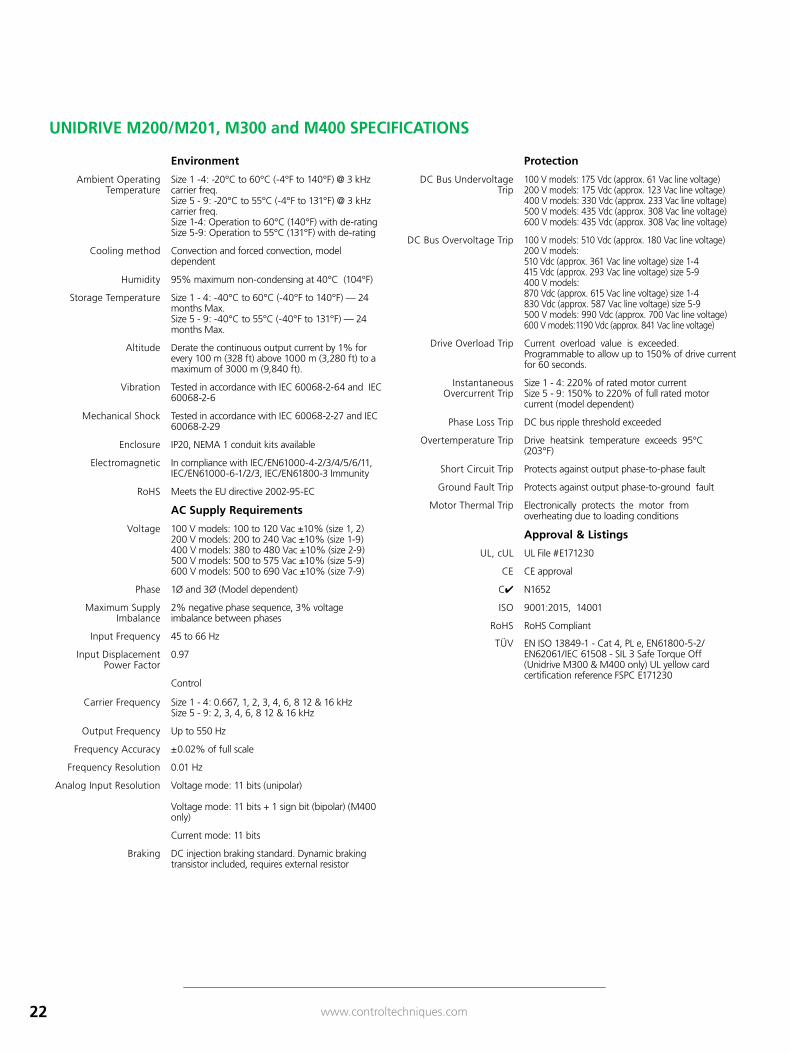
UNIDRIVE M200/M201, M300 and M400 SPECIFICATIONS
Environment
Ambient Operating Temperature
Size 1 -4: -20°C to 60°C (-4°F to 140°F) @ 3 kHz carrier freq. Size 5 - 9: -20°C to 55°C (-4°F to 131°F) @ 3 kHz carrier freq. Size 1-4: Operation to 60°C (140°F) with de-rating Size 5-9: Operation to 55°C (131°F) with de-rating
Cooling method Convection and forced convection, model dependent
Humidity 95% maximum non-condensing at 40°C (104°F)
Storage Temperature Size 1 - 4: -40°C to 60°C (-40°F to 140°F) — 24 months Max. Size 5 - 9: -40°C to 55°C (-40°F to 131°F) — 24 months Max.
Altitude Derate the continuous output current by 1% for every 100 m (328 ft) above 1000 m (3,280 ft) to a maximum of 3000 m (9,840 ft).
Vibration Tested in accordance with IEC 60068-2-64 and IEC 60068-2-6
Mechanical Shock Tested in accordance with IEC 60068-2-27 and IEC 60068-2-29
Enclosure IP20, NEMA 1 conduit kits available
Electromagnetic In compliance with IEC/EN61000-4-2/3/4/5/6/11, IEC/EN61000-6-1/2/3, IEC/EN61800-3 Immunity
RoHS Meets the EU directive 2002-95-EC
AC Supply Requirements
Voltage 100 V models: 100 to 120 Vac ±10% (size 1, 2) 200 V models: 200 to 240 Vac ±10% (size 1-9) 400 V models: 380 to 480 Vac ±10% (size 2-9) 500 V models: 500 to 575 Vac ±10% (size 5-9) 600 V models: 500 to 690 Vac ±10% (size 7-9)
Phase 1Ø and 3Ø (Model dependent)
Maximum Supply Imbalance
2% negative phase sequence, 3% voltage imbalance between phases
Input Frequency 45 to 66 Hz
Input Displacement Power Factor
0.97
Control
Carrier Frequency Size 1 - 4: 0.667, 1, 2, 3, 4, 6, 8 12 & 16 kHz Size 5 - 9: 2, 3, 4, 6, 8 12 & 16 kHz
Output Frequency Up to 550 Hz
Frequency Accuracy ±0.02% of full scale
Frequency Resolution 0.01 Hz
Analog Input Resolution Voltage mode: 11 bits (unipolar)
Voltage mode: 11 bits + 1 sign bit (bipolar) (M400 only)
Current mode: 11 bits
Braking DC injection braking standard. Dynamic braking transistor included, requires external resistor
Protection
DC Bus Undervoltage Trip
100 V models: 175 Vdc (approx. 61 Vac line voltage) 200 V models: 175 Vdc (approx. 123 Vac line voltage) 400 V models: 330 Vdc (approx. 233 Vac line voltage) 500 V models: 435 Vdc (approx. 308 Vac line voltage) 600 V models: 435 Vdc (approx. 308 Vac line voltage)
DC Bus Overvoltage Trip 100 V models: 510 Vdc (approx. 180 Vac line voltage) 200 V models: 510 Vdc (approx. 361 Vac line voltage) size 1-4 415 Vdc (approx. 293 Vac line voltage) size 5-9 400 V models: 870 Vdc (approx. 615 Vac line voltage) size 1-4 830 Vdc (approx. 587 Vac line voltage) size 5-9 500 V models: 990 Vdc (approx. 700 Vac line voltage) 600 V models: 1190 Vdc (approx. 841 Vac line voltage)
Drive Overload Trip Current overload value is exceeded. Programmable to allow up to 150% of drive current for 60 seconds.
Instantaneous Overcurrent Trip
Size 1 - 4: 220% of rated motor current Size 5 - 9: 150% to 220% of full rated motor current (model dependent)
Phase Loss Trip DC bus ripple threshold exceeded
Overtemperature Trip Drive heatsink temperature exceeds 95°C (203°F)
Short Circuit Trip Protects against output phase-to-phase fault
Ground Fault Trip Protects against output phase-to-ground fault
Motor Thermal Trip Electronically protects the motor from overheating due to loading conditions
Approval & Listings
UL, cUL UL File #E171230
CE CE approval
C✔ N1652
ISO 9001:2015, 14001
RoHS RoHS Compliant
TÜV EN ISO 13849-1 - Cat 4, PL e, EN61800-5-2/EN62061/IEC 61508 - SIL 3 Safe Torque Off (Unidrive M300 & M400 only) UL yellow card certification reference FSPC E171230
23www.controltechniques.com
11 mm(0.43 in)
W
H
D
W
H
D
W
H
D
W
H
D
H
D
WW
H
D
W
H
D
W
H
D
W
H
D
W
H
D
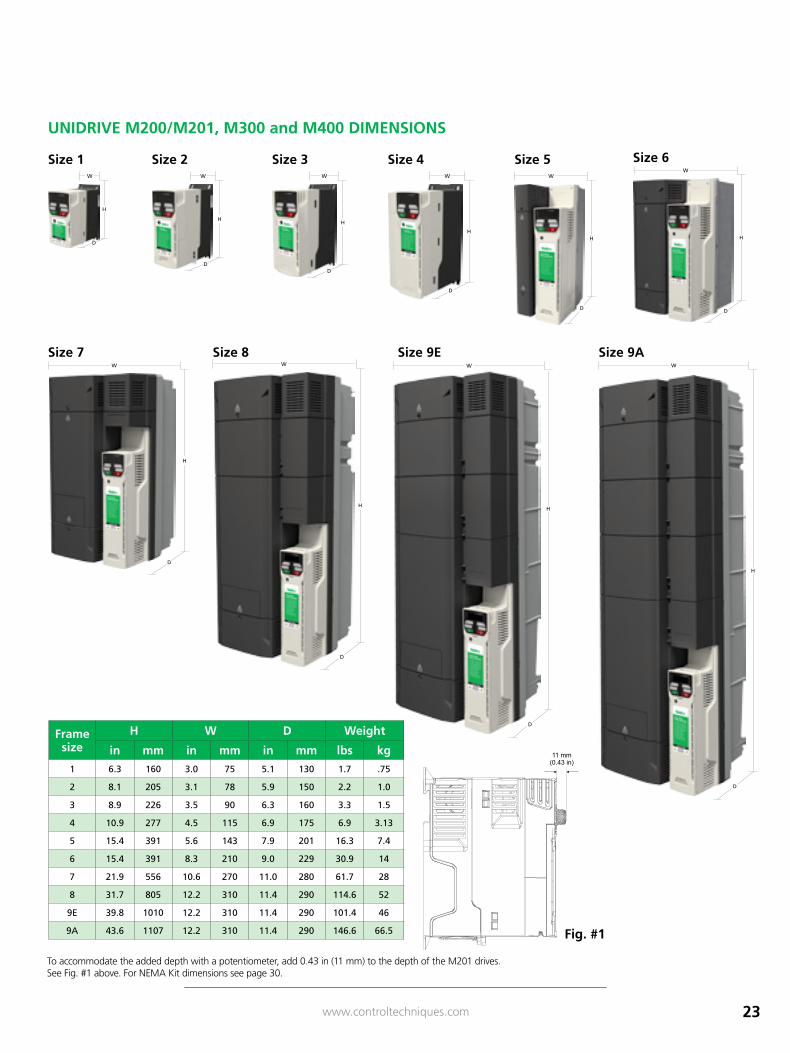
Frame size
H W D Weight
in mm in mm in mm lbs kg
1 6.3 160 3.0 75 5.1 130 1.7 .75
2 8.1 205 3.1 78 5.9 150 2.2 1.0
3 8.9 226 3.5 90 6.3 160 3.3 1.5
4 10.9 277 4.5 115 6.9 175 6.9 3.13
5 15.4 391 5.6 143 7.9 201 16.3 7.4
6 15.4 391 8.3 210 9.0 229 30.9 14
7 21.9 556 10.6 270 11.0 280 61.7 28
8 31.7 805 12.2 310 11.4 290 114.6 52
9E 39.8 1010 12.2 310 11.4 290 101.4 46
9A 43.6 1107 12.2 310 11.4 290 146.6 66.5
To accommodate the added depth with a potentiometer, add 0.43 in (11 mm) to the depth of the M201 drives. See Fig. #1 above. For NEMA Kit dimensions see page 30.
UNIDRIVE M200/M201, M300 and M400 DIMENSIONS
Size 8Size 7 Size 9E Size 9A
Size 4 Size 6Size 5Size 3Size 2
Fig. #1
Size 1
24 www.controltechniques.com
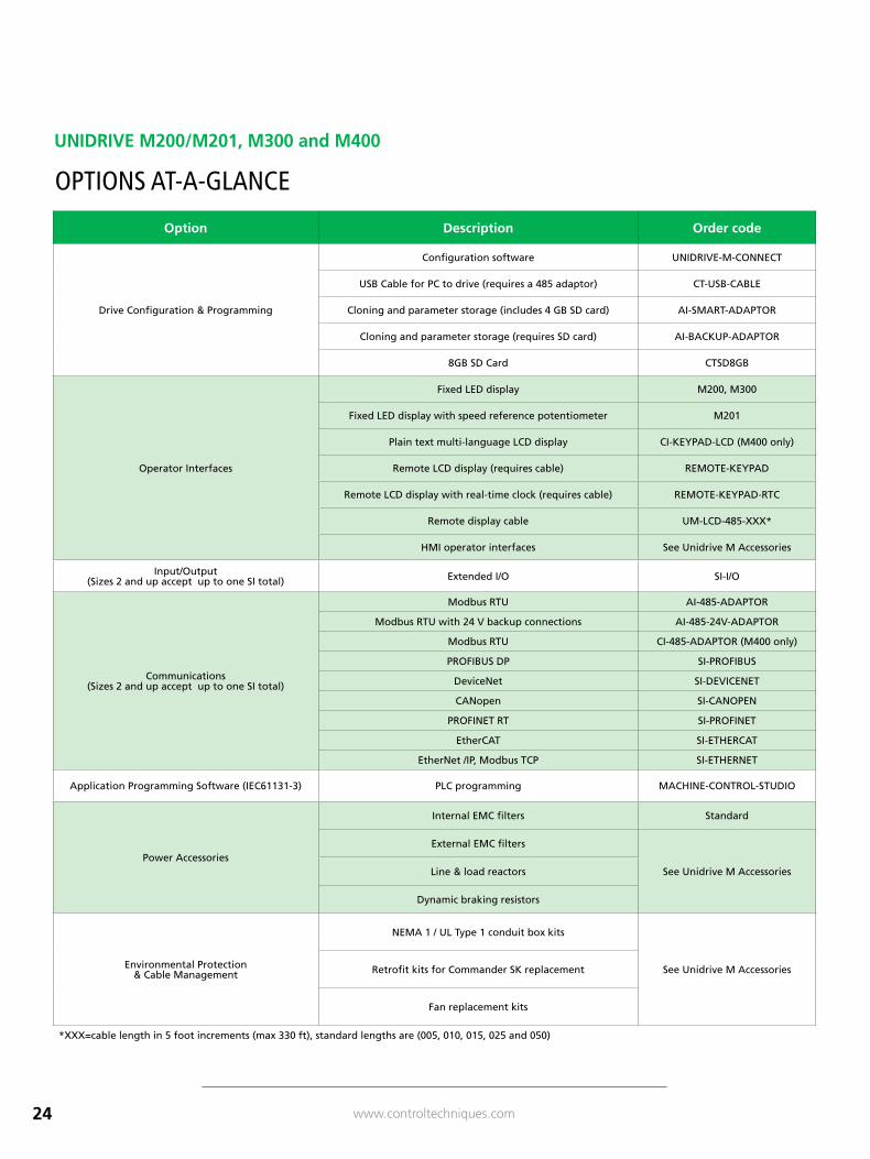
Option Description Order code
Drive Configuration & Programming
Configuration software UNIDRIVE-M-CONNECT
USB Cable for PC to drive (requires a 485 adaptor) CT-USB-CABLE
Cloning and parameter storage (includes 4 GB SD card) AI-SMART-ADAPTOR
Cloning and parameter storage (requires SD card) AI-BACKUP-ADAPTOR
8GB SD Card CTSD8GB
Operator Interfaces
Fixed LED display M200, M300
Fixed LED display with speed reference potentiometer M201
Plain text multi-language LCD display CI-KEYPAD-LCD (M400 only)
Remote LCD display (requires cable) REMOTE-KEYPAD
Remote LCD display with real-time clock (requires cable) REMOTE-KEYPAD-RTC
Remote display cable UM-LCD-485-XXX*
HMI operator interfaces See Unidrive M Accessories
Input/Output (Sizes 2 and up accept up to one SI total) Extended I/O SI-I/O
Communications (Sizes 2 and up accept up to one SI total)
Modbus RTU AI-485-ADAPTOR
Modbus RTU with 24 V backup connections AI-485-24V-ADAPTOR
Modbus RTU CI-485-ADAPTOR (M400 only)
PROFIBUS DP SI-PROFIBUS
DeviceNet SI-DEVICENET
CANopen SI-CANOPEN
PROFINET RT SI-PROFINET
EtherCAT SI-ETHERCAT
EtherNet /IP, Modbus TCP SI-ETHERNET
Application Programming Software (IEC61131-3) PLC programming MACHINE-CONTROL-STUDIO
Power Accessories
Internal EMC filters Standard
External EMC filters
See Unidrive M AccessoriesLine & load reactors
Dynamic braking resistors
Environmental Protection & Cable Management
NEMA 1 / UL Type 1 conduit box kits
See Unidrive M AccessoriesRetrofit kits for Commander SK replacement
Fan replacement kits
*XXX=cable length in 5 foot increments (max 330 ft), standard lengths are (005, 010, 015, 025 and 050)
OPTIONS AT-A-GLANCE
UNIDRIVE M200/M201, M300 and M400
25www.controltechniques.com
Drive Programming and ConfigurationParameter sets can be easily transferred between drives using an SD card with AI-BACKUP-ADAPTOR or AI-SMART-ADAPTOR.
The AI-BACKUP-ADAPTOR and AI-SMART-ADAPTOR provide fast and cost-effective drive-to-drive parameter transfer and storage using standard SD memory cards plus 24 Vdc control power back up connectivity. The smart adaptor includes a 4 GB SD card that is not
included with the backup adaptor.
Diagnostic Software
The Drive Diagnostics APP allows users to quickly diagnose faults. In the unlikely event that you get a drive error, download our free Diagnostics Tool app. It is available for Apple, Android and Windows operating systems. Just input the error code on your device and you’ll be given a solution. You can download our Diagnostics Tool App at: www.controltechniques.com/mobile-applications
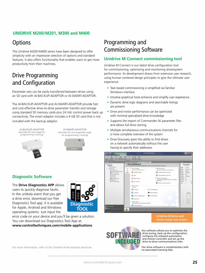
Unidrive M Connect commissioning tool Unidrive M Connect is our latest drive configuration tool for commissioning, optimizing and monitoring drive/system performance. Its development draws from extensive user research, using human centered design principles to give the ultimate user experience:
• Task based commissioning is simplified via familiar Windows interface
• Intuitive graphical tools enhance and simplify user experience
• Dynamic drive logic diagrams and searchable listings are present
• Drive and motor performance can be optimized with minimal specialized drive knowledge
• Supports the import of Commander SK parameter files and allows full drive cloning
• Multiple simultaneous communications channels for a more complete overview of the system
• Drive Discovery gives the ability to find drives on a network automatically without the user having to specify their addresses
Options The Unidrive M200-M400 series have been designed to offer simplicity with an impressive selection of options and standard features. It also offers functionality that enables users to get more productivity from their machines.
UNIDRIVE M200/M201, M300 and M400
AI-SMART-ADAPTOR (provides SD card (supplied) usage
for programming / cloning)
AI-BACKUP-ADAPTOR (provides SD card usage for
programming / cloning)
Programming and Commissioning Software
For more information, refer to the Unidrive M Accessories brochure.
Unidrive M drive and motor setup tool screen
Our software allows you to optimize the drive tuning, back up the configuration, configure the onboard automation and motion controller and set up the drive-to-drive communications links.
Our drive software is complimentary with no associated licensing fees.
SOFTWAREINCLUDED
26 www.controltechniques.com
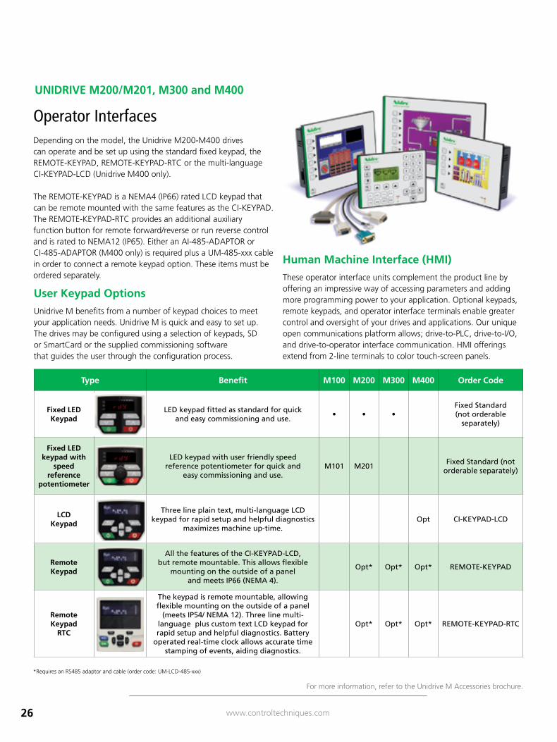
Type Benefit M100 M200 M300 M400 Order Code
Fixed LED Keypad
LED keypad fitted as standard for quick and easy commissioning and use.
• • •Fixed Standard (not orderable
separately)
Fixed LED keypad with
speed reference
potentiometer
LED keypad with user friendly speed reference potentiometer for quick and
easy commissioning and use.M101 M201
Fixed Standard (not orderable separately)
LCD Keypad
Three line plain text, multi-language LCD keypad for rapid setup and helpful diagnostics
maximizes machine up-time. Opt CI-KEYPAD-LCD
Remote Keypad
All the features of the CI-KEYPAD-LCD, but remote mountable. This allows flexible
mounting on the outside of a panel and meets IP66 (NEMA 4).
Opt* Opt* Opt* REMOTE-KEYPAD
Remote Keypad
RTC
The keypad is remote mountable, allowing flexible mounting on the outside of a panel
(meets IP54/ NEMA 12). Three line multi-language plus custom text LCD keypad for rapid setup and helpful diagnostics. Battery
operated real-time clock allows accurate time stamping of events, aiding diagnostics.
Opt* Opt* Opt* REMOTE-KEYPAD-RTC
Operator Interfaces Depending on the model, the Unidrive M200-M400 drives can operate and be set up using the standard fixed keypad, the REMOTE-KEYPAD, REMOTE-KEYPAD-RTC or the multi-language CI-KEYPAD-LCD (Unidrive M400 only).
The REMOTE-KEYPAD is a NEMA4 (IP66) rated LCD keypad that can be remote mounted with the same features as the CI-KEYPAD. The REMOTE-KEYPAD-RTC provides an additional auxiliary function button for remote forward/reverse or run reverse control and is rated to NEMA12 (IP65). Either an AI-485-ADAPTOR or CI-485-ADAPTOR (M400 only) is required plus a UM-485-xxx cable in order to connect a remote keypad option. These items must be ordered separately.
UNIDRIVE M200/M201, M300 and M400
User Keypad Options Unidrive M benefits from a number of keypad choices to meet your application needs. Unidrive M is quick and easy to set up. The drives may be configured using a selection of keypads, SD or SmartCard or the supplied commissioning software that guides the user through the configuration process.
Human Machine Interface (HMI) These operator interface units complement the product line by offering an impressive way of accessing parameters and adding more programming power to your application. Optional keypads, remote keypads, and operator interface terminals enable greater control and oversight of your drives and applications. Our unique open communications platform allows; drive-to-PLC, drive-to-I/O, and drive-to-operator interface communication. HMI offerings extend from 2-line terminals to color touch-screen panels.
For more information, refer to the Unidrive M Accessories brochure.
*Requires an RS485 adaptor and cable (order code: UM-LCD-485-xxx)
27www.controltechniques.com
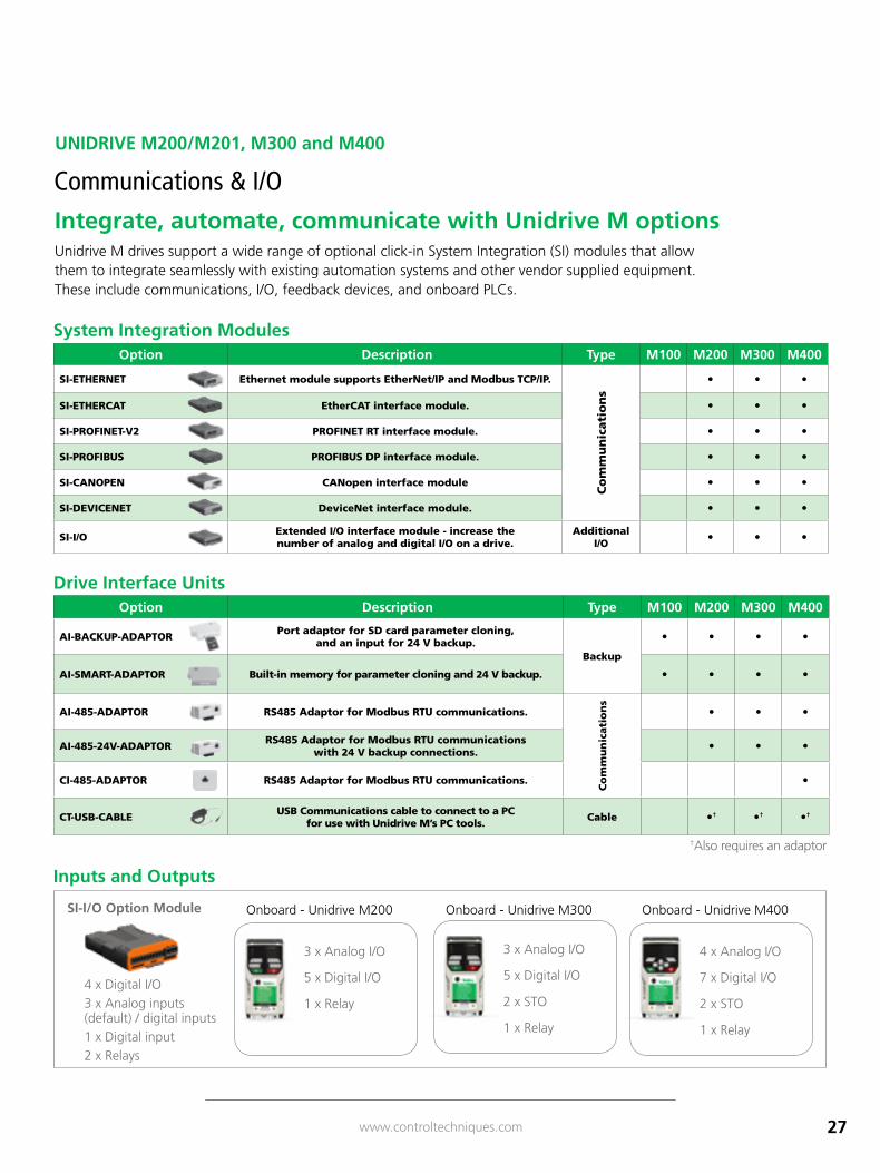
Option Description Type M100 M200 M300 M400
AI-BACKUP-ADAPTOR Port adaptor for SD card parameter cloning, and an input for 24 V backup.
Backup
• • • •
AI-SMART-ADAPTOR Built-in memory for parameter cloning and 24 V backup. • • • •
AI-485-ADAPTOR RS485 Adaptor for Modbus RTU communications.
Co
mm
un
icati
on
s
• • •
AI-485-24V-ADAPTOR RS485 Adaptor for Modbus RTU communications with 24 V backup connections. • • •
CI-485-ADAPTOR RS485 Adaptor for Modbus RTU communications. •
CT-USB-CABLE USB Communications cable to connect to a PC for use with Unidrive M’s PC tools. Cable •† •† •†
Option Description Type M100 M200 M300 M400
SI-ETHERNET Ethernet module supports EtherNet/IP and Modbus TCP/IP.
Co
mm
un
icati
on
s
• • •
SI-ETHERCAT EtherCAT interface module. • • •
SI-PROFINET-V2 PROFINET RT interface module. • • •
SI-PROFIBUS PROFIBUS DP interface module. • • •
SI-CANOPEN CANopen interface module • • •
SI-DEVICENET DeviceNet interface module. • • •
SI-I/O Extended I/O interface module - increase the number of analog and digital I/O on a drive.
Additional I/O • • •
Unidrive M drives support a wide range of optional click-in System Integration (SI) modules that allow them to integrate seamlessly with existing automation systems and other vendor supplied equipment. These include communications, I/O, feedback devices, and onboard PLCs.
Integrate, automate, communicate with Unidrive M options
Communications & I/O
UNIDRIVE M200/M201, M300 and M400
†Also requires an adaptor
SI-I/O Option Module
4 x Digital I/O3 x Analog inputs (default) / digital inputs1 x Digital input2 x Relays
Inputs and Outputs
Onboard - Unidrive M400Onboard - Unidrive M200 Onboard - Unidrive M300
4 x Analog I/O
7 x Digital I/O
2 x STO
1 x Relay
3 x Analog I/O
5 x Digital I/O
1 x Relay
3 x Analog I/O
5 x Digital I/O
2 x STO
1 x Relay
System Integration Modules
Drive Interface Units
28 www.controltechniques.com
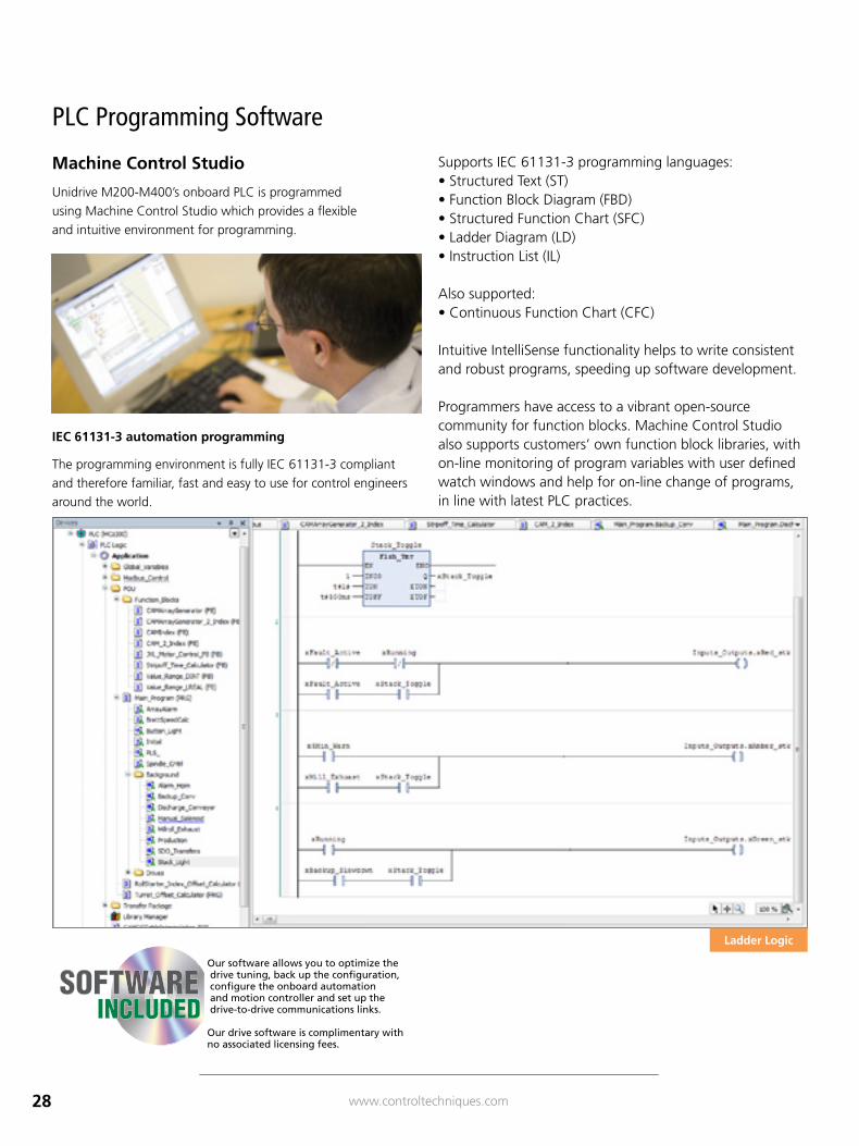
Ladder Logic
Machine Control Studio Unidrive M200-M400’s onboard PLC is programmed using Machine Control Studio which provides a flexible and intuitive environment for programming.
IEC 61131-3 automation programming The programming environment is fully IEC 61131-3 compliant and therefore familiar, fast and easy to use for control engineers around the world.
Supports IEC 61131-3 programming languages:• Structured Text (ST)• Function Block Diagram (FBD)• Structured Function Chart (SFC)• Ladder Diagram (LD)• Instruction List (IL)
Also supported:• Continuous Function Chart (CFC)
Intuitive IntelliSense functionality helps to write consistent and robust programs, speeding up software development.
Programmers have access to a vibrant open-source community for function blocks. Machine Control Studio also supports customers’ own function block libraries, with on-line monitoring of program variables with user defined watch windows and help for on-line change of programs, in line with latest PLC practices.
PLC Programming Software
Our software allows you to optimize the drive tuning, back up the configuration, configure the onboard automation and motion controller and set up the drive-to-drive communications links.
Our drive software is complimentary with no associated licensing fees.
SOFTWAREINCLUDED
29www.controltechniques.com
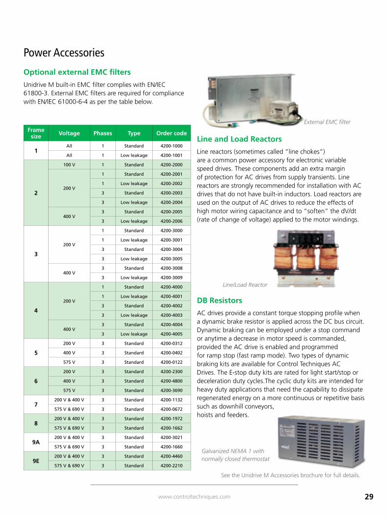
Frame size Voltage Phases Type Order code
1All 1 Standard 4200-1000
All 1 Low leakage 4200-1001
2
100 V 1 Standard 4200-2000
200 V
1 Standard 4200-2001
1 Low leakage 4200-2002
3 Standard 4200-2003
3 Low leakage 4200-2004
400 V3 Standard 4200-2005
3 Low leakage 4200-2006
3
200 V
1 Standard 4200-3000
1 Low leakage 4200-3001
3 Standard 4200-3004
3 Low leakage 4200-3005
400 V3 Standard 4200-3008
3 Low leakage 4200-3009
4
200 V
1 Standard 4200-4000
1 Low leakage 4200-4001
3 Standard 4200-4002
3 Low leakage 4200-4003
400 V3 Standard 4200-4004
3 Low leakage 4200-4005
5
200 V 3 Standard 4200-0312
400 V 3 Standard 4200-0402
575 V 3 Standard 4200-0122
6
200 V 3 Standard 4200-2300
400 V 3 Standard 4200-4800
575 V 3 Standard 4200-3690
7200 V & 400 V 3 Standard 4200-1132
575 V & 690 V 3 Standard 4200-0672
8200 V & 400 V 3 Standard 4200-1972
575 V & 690 V 3 Standard 4200-1662
9A200 V & 400 V 3 Standard 4200-3021
575 V & 690 V 3 Standard 4200-1660
9E200 V & 400 V 3 Standard 4200-4460
575 V & 690 V 3 Standard 4200-2210
Power Accessories
Optional external EMC filters
Unidrive M built-in EMC filter complies with EN/IEC 61800-3. External EMC filters are required for compliance with EN/IEC 61000-6-4 as per the table below.
Line and Load Reactors
Line reactors (sometimes called “line chokes”) are a common power accessory for electronic variable speed drives. These components add an extra margin of protection for AC drives from supply transients. Line reactors are strongly recommended for installation with AC drives that do not have built-in inductors. Load reactors are used on the output of AC drives to reduce the effects of high motor wiring capacitance and to “soften” the dV/dt (rate of change of voltage) applied to the motor windings.
See the Unidrive M Accessories brochure for full details.
DB Resistors
AC drives provide a constant torque stopping profile when a dynamic brake resistor is applied across the DC bus circuit. Dynamic braking can be employed under a stop command or anytime a decrease in motor speed is commanded, provided the AC drive is enabled and programmed for ramp stop (fast ramp mode). Two types of dynamic braking kits are available for Control Techniques AC Drives. The E-stop duty kits are rated for light start/stop or deceleration duty cycles.The cyclic duty kits are intended for heavy duty applications that need the capability to dissipate regenerated energy on a more continuous or repetitive basis such as downhill conveyors, hoists and feeders.
Galvanized NEMA 1 with normally closed thermostat
External EMC filter
Line/Load Reactor
30 www.controltechniques.com
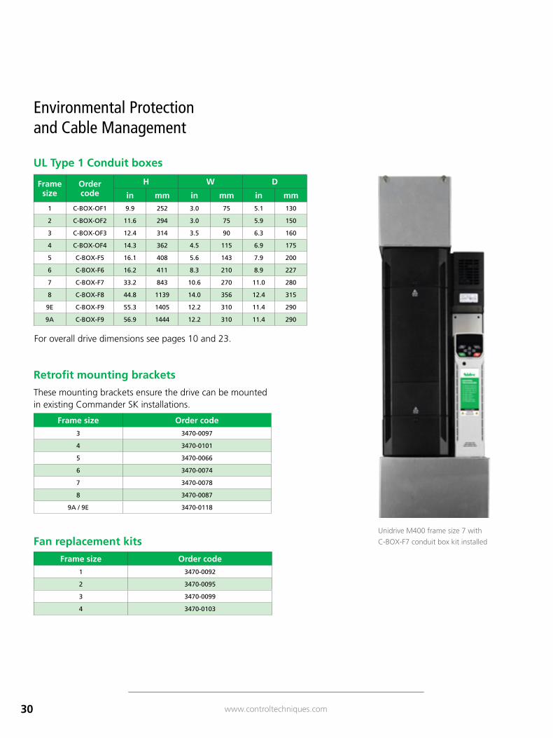
Frame size
Order code
H W D
in mm in mm in mm1 C-BOX-OF1 9.9 252 3.0 75 5.1 130
2 C-BOX-OF2 11.6 294 3.0 75 5.9 150
3 C-BOX-OF3 12.4 314 3.5 90 6.3 160
4 C-BOX-OF4 14.3 362 4.5 115 6.9 175
5 C-BOX-F5 16.1 408 5.6 143 7.9 200
6 C-BOX-F6 16.2 411 8.3 210 8.9 227
7 C-BOX-F7 33.2 843 10.6 270 11.0 280
8 C-BOX-F8 44.8 1139 14.0 356 12.4 315
9E C-BOX-F9 55.3 1405 12.2 310 11.4 290
9A C-BOX-F9 56.9 1444 12.2 310 11.4 290
For overall drive dimensions see pages 10 and 23.
Frame size Order code1 3470-0092
2 3470-0095
3 3470-0099
4 3470-0103
Frame size Order code3 3470-0097
4 3470-0101
5 3470-0066
6 3470-0074
7 3470-0078
8 3470-0087
9A / 9E 3470-0118
Retrofit mounting brackets
UL Type 1 Conduit boxes
Environmental Protection and Cable Management
Unidrive M400 frame size 7 with
C-BOX-F7 conduit box kit installedFan replacement kits
These mounting brackets ensure the drive can be mounted in existing Commander SK installations.
31www.controltechniques.com
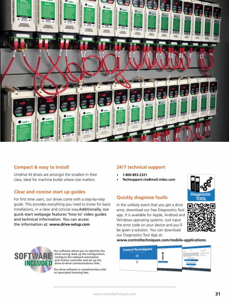
Compact & easy to install
Unidrive M drives are amongst the smallest in their class, ideal for machine builds where size matters.
Clear and concise start up guides
For first time users, our drives come with a step-by-step guide. This provides everything you need to know for basic installations, in a clear and concise way.Additionally, our quick-start webpage features ‘how to’ video guides and technical information. You can access the information at: www.drive-setup.com
24/7 technical support • 1-800-893-2321 • [email protected]
Quickly diagnose faults
In the unlikely event that you get a drive error, download our free Diagnostics Tool app. It is available for Apple, Android and Windows operating systems. Just input the error code on your device and you’ll be given a solution. You can download our Diagnostics Tool App at: www.controltechniques.com/mobile-applications
Our software allows you to optimize the drive tuning, back up the configuration, configure the onboard automation and motion controller and set up the drive-to-drive communications links.
Our drive software is complimentary with no associated licensing fees.
SOFTWAREINCLUDED
www.controltechniques.com
Connect with us at:
twitter.com/Nidec_CT
facebook.com/NidecControlTechniques
youtube.com/c/NidecControlTechniques
linkedin.com/company/17944319
theautomationengineer.com (blog)
P.N. CAT-GP 01/18
© 2018 Control Techniques Americas, division of Nidec Motor Corporation. The information contained in this brochure is for guidance only and does not form part of any contract. The accuracy cannot be guaranteed as the Company has an ongoing process of development and reserve the right to change the specification of their products without notice.
Control Techniques Americas, division of Nidec Motor Corporation, 7078 Shady Oak Road Eden Prairie, MN 55344-3505 USA.