unidrive m400 quick start guide english iss3 techniques... · unidrive m400 quick start guide...
TRANSCRIPT

Quick Start Guide
Unidrive M400 Frame sizes 1 to 4
Manufacturing Automation drive Fast set-up and diagnosis with real-text display, plus integrated CODESYS based PLC
Part Number: 0478-0040-06Issue: 6
Unidrive M400 Quick Start Guide English Iss3.book Page 1 Tuesday, September 15, 2015 9:32 AM

This guide is intended to provide basic information required in order to set-up a drive to run a motor. For more detailed installation information, please refer to the Unidrive M400 User Guide which is available to download from:http://www.emersonindustrial.com/en-EN/controltechniques/downloads/userguidesandsoftware/Pages/downloads.aspx. or www.emersonindustrial.com/en-EN/leroy-somer-motors-drives/downloads/Pages/manuals.aspx.
Warnings, Cautions and Notes
Copyright © September 2015 Issue Number: 6
A Warning contains information which is essential for avoiding a safety hazard.
A Caution contains information which is necessary for avoiding a risk of damage to the product or other equipment.
A Note contains information, which helps to ensure correct operation of the product.
This guide does not include safety information. Incorrect installation or operation of the drive, could cause personnel injury or equipment damage. For essential safety information, please refer to the Unidrive M400 User Guide or the safety booklet supplied with the drive.
WARNING
CAUTION
NOTE
WARNING
Unidrive M400 Quick Start Guide English Iss3.book Page 2 Tuesday, September 15, 2015 9:32 AM
Unidrive M400 Quick Start GuideIssue Number: 6
Contents1 Product information ....................................................................................71.1 Ratings .................................................................................................................... 7
2 Options .........................................................................................................83 Mechanical installation ...............................................................................94 Electrical installation .................................................................................124.1 AC supply requirements ........................................................................................ 124.2 External braking resistor ........................................................................................ 124.3 Ground leakage ..................................................................................................... 144.4 Control terminal configurations and wiring ............................................................. 154.5 EMC ....................................................................................................................... 214.6 Safe Torque Off (STO) .......................................................................................... 22
5 Optional LCD keypad and display ...........................................................235.1 Saving parameters ................................................................................................ 245.2 Restoring parameter defaults ................................................................................ 24
6 Basic parameters (Menu 0) .......................................................................256.1 Menu 0: Basic parameters ..................................................................................... 256.2 Unidrive M400 parameter descriptions .................................................................. 30
7 Running the motor ....................................................................................498 Diagnostics ................................................................................................509 NV Media Card Operation .........................................................................5510 Machine Control Studio ............................................................................5611 UL listing information ...............................................................................5711.1 General .................................................................................................................. 5711.2 Mounting ................................................................................................................ 5711.3 Environment .......................................................................................................... 5711.4 Electrical ratings .................................................................................................... 5711.5 Opening of branch circuit ....................................................................................... 5711.6 Electrical installation .............................................................................................. 5711.7 Motor overload protection ...................................................................................... 5811.8 Motor overspeed protection ................................................................................... 5811.9 Thermal memory retention ..................................................................................... 5811.10 Group installation ................................................................................................... 5911.11 UL listed accessories ............................................................................................. 59
Unidrive M400 Quick Start Guide English Iss3.book Page 3 Tuesday, September 15, 2015 9:32 AM

4 Unidrive M400 Quick Start GuideIssue Number: 6
Declaration of Conformity
This declaration applies to the Unidrive-M product range comprising model numbers listed below:
The model number may be followed by additional characters that do not affect the ratings.The variable speed drive products listed above have been designed and manufactured in accordance with the following European harmonized standards:
EN 61000-3-2: 2006 Applicable where input current < 16 A. No limits apply for professional equipment where input power ≥1 kW.These products comply with the Restriction of Hazardous Substances Directive - RoHS 2011/65/EU, the Low Voltage Directive - LVD 2006/95/EC and the Electromagnetic Compatibility Directive - EMC 2004/108/EC.
These electronic drive products are intended to be used with appropriate motors, controllers, electrical protection components and other equipment to form complete end products or systems. Compliance with safety and EMC regulations depends upon installing and configuring drives correctly, including using the specified input filters. The drives must be installed only by professional installers who are familiar with requirements for safety and EMC. The assembler is responsible for ensuring that the end product or system complies with all the relevant laws in the country where it is to be used. Refer to the User Guide. An EMC data sheet is also available giving detailed EMC information.
Control Techniques LtdThe GroNewtownPowysUKSY16 3BE
Moteurs Leroy-SomerUsine des AgriersBoulevard Marcellin LeroyCS1001516915 Angoulême Cedex 9France
Model No. Interpretation Format: Xaaa-bbc ddddde Format: Xaa-bbc ddddde
X Application M = Manufacturing Automation, E = Elevator, F = Flow, H = HVAC, CSD = Compressor HS = High Speed
aa(a) Control System 100, 101, 200, 201, 300, 400, 600, 700, 701, 702 70, 71, 72bb Frame Size 01, 02, 03, 04, 05, 06, 07, 08, 09, 10, 11c Voltage Rating 1 = 100 V, 2 = 200 V, 4 = 400 V, 5 = 575 V, 6 = 690 Vddddd Current Rating Example 01000 = 100 A
e ConfigurationA = AC in AC out (with internal choke), D = DC in AC out (Inverter), C = AC in DC out (Rectifier), E = AC in AC out (without internal choke), T = AC in AC out with Dual Rectifier
EN 61800-5-1:2007 Adjustable speed electrical power drive systems - Part 5-1: Safety requirements - Electrical, thermal and energy
EN 61800-3: 2004 Adjustable speed electrical power drive systems - Part 3: EMC requirements and specific test methods
EN 61000-6-2:2005 Electromagnetic compatibility (EMC) - Part 6-2: Generic standards - Immunity for industrial environments
EN 61000-6-4:2007 Electromagnetic compatibility (EMC) - Part 6-4: Generic standards - Emission standard for industrial environments
EN 61000-3-2:2006 Electromagnetic compatibility (EMC) - Part 3-2: Limits for harmonic current emissions (equipment input current ≤16 A per phase)
EN 61000-3-3:2008Electromagnetic compatibility (EMC) - Part 3-3: Limitation of voltage changes, voltage fluctuations and flicker in public, low voltage supply systems, for equipment with rated current ≤16 A per phase and not subject to conditional connection
G. WilliamsVice President, TechnologyDate: 30th July 2015Place: Newtown, Powys, UK
Unidrive M400 Quick Start Guide English Iss3.book Page 4 Tuesday, September 15, 2015 9:32 AM

Unidrive M400 Quick Start Guide English Iss3.book Page 5 Tuesday, September 15, 2015 9:32 AM
Declaration of Conformity (including 2006 Machinery Directive)
This declaration applies to the Unidrive-M product range comprising model numbers listed below:
The model number may be followed by additional characters that do not affect the ratings.This declaration relates to these products when used as a safety component of a machine. Only the Safe Torque Off function may be used for a safety function of a machine. None of the other functions of the drive may be used to carry out a safety function.These products fulfil all the relevant provisions of the Machinery Directive 2006/42/EC and the EMC Directive 2014/108/EC.EC type examination has been carried out by the following notified body:
TUV Rheinland Industrie Service GmbHAm Grauen SteinD-51105 KölnGermany
Notified body identification number: 0035
EC type-examination certificate numbers:01/205/5270.01/14 dated 2014-11-1101/205/5387.01/15 dated 2015-01-2901/205/5383.02/15 dated 2015-04-21
The harmonised standards used are shown below:
Control Techniques LtdThe GroNewtownPowysUKSY16 3BE
Moteurs Leroy-SomerUsine des AgriersBoulevard Marcellin LeroyCS1001516915 Angoulême Cedex 9France
Model No. Interpretation Format: Xaaa-bbc ddddde Format: Xaa-bbc ddddde
X Application M = Manufacturing Automation, E = Elevator, F = Flow, H = HVAC, CSD = Compressor HS = High Speed
aa(a) Control System 100, 101, 200, 201, 300, 400, 600, 700, 701, 702 70, 71, 72bb Frame Size 01, 02, 03, 04, 05, 06, 07, 08, 09, 10, 11c Voltage Rating 1 = 100 V, 2 = 200 V, 4 = 400 V, 5 = 575 V, 6 = 690 Vddddd Current Rating Example 01000 = 100 A
e ConfigurationA = AC in AC out (with internal choke), D = DC in AC out (Inverter), C = AC in DC out (Rectifier), E = AC in AC out (without internal choke), T = AC in AC out with Dual Rectifier
EN 61800-5-1:2007 Adjustable speed electrical power drive systems - Part 5-1: Safety requirements - Electrical, thermal and energy
EN 61800-5-2:2007 Adjustable speed electrical power drive systems - Part 5-2: Safety requirements - Functional
EN ISO 13849-1:2008 Safety of Machinery, Safety-related parts of control systems, General principles for design
EN ISO 13849-2:2008 Safety of machinery, Safety-related parts of control systems. Validation
EN 61800-3: 2004 Adjustable speed electrical power drive systems - Part 3: EMC requirements and specific test methods
EN 62061:2005 Safety of machinery, Functional safety of safety related electrical, electronic and programmable electronic control systems
Unidrive M400 Quick Start Guide 5Issue Number: 6

Unidrive M400 Quick Start Guide English Iss3.book Page 6 Tuesday, September 15, 2015 9:32 AM
Person authorised to complete the technical file:C HargisChief EngineerNewtown, Powys, UK
IMPORTANT NOTICEThese electronic drive products are intended to be used with appropriate motors, controllers, electrical protection components and other equipment to form complete end products or systems. It is the responsibility of the installer to ensure that the design of the complete machine, including its safety-related control system, is carried out in accordance with the requirements of the Machinery Directive and any other relevant legislation. The use of a safety-related drive in itself does not ensure the safety of the machine.
Compliance with safety and EMC regulations depends upon installing and configuring drives correctly, including using the specified input filters. The drive must be installed only by professional installers who are familiar with requirements for safety and EMC. The assembler is responsible for ensuring that the end product or system complies with all relevant laws in the country where it is to be used. For more information regarding Safe Torque Off, refer to the Drive User Guide.
G. WilliamsVice President, TechnologyDate: 1st July 2015Place: Newtown, Powys, UK
6 Unidrive M400 Quick Start GuideIssue Number: 6

Unidrive M400 Quick Start Guide English Iss3.book Page 7 Tuesday, September 15, 2015 9:32 AM
1 Product information1.1 Ratings
ModelInput
phases
Max.cont input
current
Max input fuse rating
Nominal cable size Output currentEuropean USA
1 Ph 3 Ph Input Output Input OutputMax.cont
output current
Nominal power
Motor power
ph A A A mm2 mm2 AWG AWG A kW hp01100017 1 8.7 10 1 1 16 16 1.7 0.25 0.3301100024 1 11.1 16 1 1 14 16 2.4 0.37 0.501200017 1 4.5 6 1 1 16 16 1.7 0.25 0.3301200024 1 5.3 6 1 1 16 16 2.4 0.37 0.501200033 1 8.3 10 1 1 16 16 3.3 0.55 0.7501200042 1 10.4 16 1 1 16 16 4.2 0.75 102100042 1 18.8 20 2.5 1 12 16 4.2 0.75 102100056 1 24 25 4 1 10 16 5.6 1.1 1.502200024 1 / 3 5.3/4.1 6 6 1 1 16 16 2.4 0.37 0.502200033 1 / 3 8.3/6.7 10 10 1 1 16 16 3.3 0.55 0.7502200042 1 / 3 10.4/7.5 16 10 1 1 16 16 4.2 0.75 102200056 1 / 3 14.9/11.3 20 15 2.5/1.5 1 12/14 16 5.6 1.1 1.502200075 1 / 3 18.1/13.5 20 15 2.5 1 12 16 7.5 1.5 202400013 3 2.4 6 1 1 16 16 1.3 0.37 0.502400018 3 2.9 6 1 1 16 16 1.8 0.55 0.7502400023 3 3.5 6 1 1 16 16 2.3 0.75 102400032 3 5.1 6 1 1 16 16 3.2 1.1 1.502400041 3 6.2 10 1 1 16 16 4.1 1.5 203200100 1 / 3 23.9/17.7 25 20 4 1.5 10/12 14 10 2.2 303400056 3 8.7 10 1 1 14 16 5.6 2.2 303400073 3 12.2 16 1.5 1 12 16 7.3 3 303400094 3 14.8 16 2.5 1.5 12 14 9.4 4 504200133 1 / 3 23.7/16.9 25 20 4/2.5 2.5 10 12 13.3 3 304200176 3 21.3 25 4 2.5 10 12 17.6 4 504400135 3 16.3 20 2.5 2.5 10 12 13.5 5.5 7.504400170 3 20.7 25 4 2.5 10 12 17 7.5 10
The nominal cable sizes shown in the table above, are provided as a guide only. Ensure that the cables used conform to the local wiring regulations.
NOTE
Unidrive M400 Quick Start Guide 7Issue Number: 6

Unidrive M400 Quick Start Guide English Iss3.book Page 8 Tuesday, September 15, 2015 9:32 AM
Figure 1-1 Model number structure
2 OptionsTable 2-1 System Integration (SI) option module identification
Type Option module Color Name Further details
Fieldbus
Purple SI-PROFIBUS
See relevant option module User Guide
MediumGrey SI-DeviceNet
Light Grey SI-CANopen
Beige SI-Ethernet
Brown Red SI-EtherCAT
Automation(I/O expansion) Orange SI-I/O
Product line:
Frame size:
Current Rating :Heavy Duty current rating x10
Drive Format :A – AC in AC out
Voltage rating:1 - 100 V (100 - 120 10 %)± 2 - 200 V (200 - 240 10 %)± 4 - 400 V (380 - 480 10 %)± 5 - 575 V (500 - 575 10 %)± 6 - 690 V (500 - 690 10 %)±
Derivative Electrical SpecificationsM400 - 03 4 00073 A
8 Unidrive M400 Quick Start GuideIssue Number: 6

Unidrive M400 Quick Start Guide English Iss3.book Page 9 Tuesday, September 15, 2015 9:32 AM
Table 2-2 Adaptor Interface (AI) option module identification
3 Mechanical installationThe drives can be panel mounted with 0 mm space between the drives. For further information on mechanical installation refer to the Drive User Guide.
To remove the terminal cover, use a flat bladed screwdriver to rotate the terminal cover locating clip by approximately 30° in a counter clockwise direction, and then slide the cover down.
Type Option module Name Further Details
Communications AI-485 Adaptor
See Drive User Guide
BackupAI-Backup Adaptor
AI-Smart Adaptor
DriveSize
H W D M1 M2 ∅ A B*mm in mm in mm in mm in mm in mm in mm in mm in
1 160 6.30 75 2.95 130 5.12 143 5.70 53 2.08 5 0.2
0 0.00 100 3.932 205 8.07 78 3.07 150 5.91 194 7.63 55 2.17 5 0.23 226 8.90 90 3.54 160 6.30 215 8.46 70.7 2.80 5 0.24 277 10.91 115 4.53 175 6.89 265 10.43 86 3.40 6 0.23
A minimum clearance of 100 mm above and below Frame 01 to 04 products is required for applications where the product is subjected to rated load and rated ambient temperature.
A
W
M2
M2
B
B A
H M1Coverrelease
NOTE
Unidrive M400 Quick Start Guide 9Issue Number: 6
Unidrive M400 Quick Start Guide English Iss3.book Page 10 Tuesday, September 15, 2015 9:32 AM
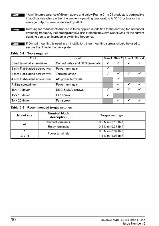
Table 3-1 Tools required
Table 3-2 Recommended torque settings
* A minimum clearance of 50 mm above and below Frame 01 to 04 products is permissible in applications where either the ambient operating temperature is 35 °C or less or the average output current is derated by 20 %.
Derating for reduced clearances is to be applied in addition to the derating for increased switching frequency if operating above 3 kHz. Refer to the Drive User Guide for the current derating due to an increase in switching frequency.
If Din rail mounting is used in an installation, then mounting screws should be used to secure the drive to the back plate.
Tool Location Size 1 Size 2 Size 3 Size 4Small terminal screwdriver Control, relay and STO terminals
3 mm Flat-bladed screwdriver Power terminals
5 mm Flat-bladed screwdriver Terminal cover
4 mm Flat-bladed screwdriver AC power terminals
Philips screwdriver Power terminals
Torx 10 driver EMC & MOV screws
Torx 15 driver Fan screw
Torx 20 driver Fan screw
Model size Terminal block description Torque settings
AllControl terminals 0.2 N m (0.15 Ib ft)Relay terminals 0.5 N m (0.37 Ib ft)
1Power terminals
0.5 N m (0.37 Ib ft)2, 3, 4 1.4 N m (1.03 Ib ft)
NOTE
NOTE
NOTE
10 Unidrive M400 Quick Start GuideIssue Number: 6

Unidrive M400 Quick Start Guide English Iss3.book Page 11 Tuesday, September 15, 2015 9:32 AM
Figure 3-1 Feature diagram (size 2 shown)
7
9
4
1
3
6
8
2
5
11
10
12
13
Key1. Rating label (On side of drive)2. Identification label3. Option module connection4. Relay connections5. Control connections6. Braking terminal7. Internal EMC filter screw8. DC bus +9. DC bus -10. Motor connections11. AC supply connections12. Ground connections13. Safe Torque Off connections
Unidrive M400 Quick Start Guide 11Issue Number: 6
Unidrive M400 Quick Start Guide English Iss3.book Page 12 Tuesday, September 15, 2015 9:32 AM
4 Electrical installationAn overlay of the electrical connections / terminals is included on the back page of this manual.
4.1 AC supply requirementsVoltage:
100 V drive: 100 V to 120 V ±10 % 200 V drive: 200 V to 240 V ±10 %400 V drive: 380 V to 480 V ±10 %
Number of phases: 3Maximum supply imbalance: 2 % negative phase sequence (equivalent to 3 % voltage imbalance between phases).Frequency range: 45 to 66 Hz
For UL compliance only, the maximum supply symmetrical fault current must be limited to 100 kA.
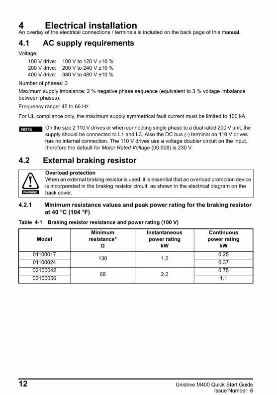
4.2 External braking resistor
4.2.1 Minimum resistance values and peak power rating for the braking resistor at 40 °C (104 °F)
Table 4-1 Braking resistor resistance and power rating (100 V)
On the size 2 110 V drives or when connecting single phase to a dual rated 200 V unit, the supply should be connected to L1 and L3. Also the DC bus (-) terminal on 110 V drives has no internal connection. The 110 V drives use a voltage doubler circuit on the input, therefore the default for Motor Rated Voltage (00.008) is 230 V.
Overload protection When an external braking resistor is used, it is essential that an overload protection device is incorporated in the braking resistor circuit; as shown in the electrical diagram on the back cover.
ModelMinimum
resistance*Ω
Instantaneouspower rating
kW
Continuouspower rating
kW01100017
130 1.20.25
01100024 0.3702100042
68 2.20.75
02100056 1.1
NOTE
WARNING
12 Unidrive M400 Quick Start GuideIssue Number: 6
Unidrive M400 Quick Start Guide English Iss3.book Page 13 Tuesday, September 15, 2015 9:32 AM
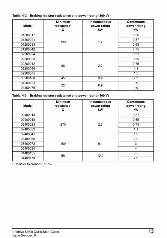
Table 4-2 Braking resistor resistance and power rating (200 V)
Table 4-3 Braking resistor resistance and power rating (400 V)
* Resistor tolerance: ±10 %
ModelMinimum
resistance*Ω
Instantaneouspower rating
kW
Continuouspower rating
kW01200017
130 1.2
0.2501200024 0.3701200033 0.5501200042 0.7502200024
68 2.2
0.3702200033 0.5502200042 0.7502200056 1.102200075 1.503200100 45 3.4 2.204200133
22 6.93.0
04200176 4.0
ModelMinimum
resistance*Ω
Instantaneouspower rating
kW
Continuouspower rating
kW02400013
270 2.3
0.3702400018 0.5502400023 0.7502400032 1.102400041 1.503400056
100 6.12.2
03400073 303400094 404400135
50 12.25.5
04400170 7.5
Unidrive M400 Quick Start Guide 13Issue Number: 6
Unidrive M400 Quick Start Guide English Iss3.book Page 14 Tuesday, September 15, 2015 9:32 AM
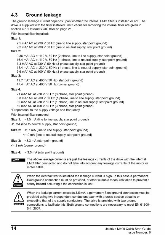
4.3 Ground leakage The ground leakage current depends upon whether the internal EMC filter is installed or not. The drive is supplied with the filter installed. Instructions for removing the internal filter are given in section 4.5.1 Internal EMC filter on page 21.With internal filter installed:Size 1:
2.5 mA* AC at 230 V 50 Hz (line to line supply, star point ground)9.2 mA* AC at 230 V 50 Hz (line to neutral supply, star point ground)
Size 2: 9.36 mA* AC at 110 V, 50 Hz (2 phase, line to line supply, star point ground)16.4 mA* AC at 110 V, 50 Hz (1 phase, line to neutral supply, star point ground)5.3 mA* AC at 230 V, 50 Hz (3 phase supply, star point ground)15.4 mA* AC at 230 V, 50 Hz (1 phase, line to neutral supply, star point ground)9.6 mA* AC at 400 V, 50 Hz (3 phase supply, star point ground)
Size 3: 19.7 mA* AC at 400 V 50 Hz (star point ground)47.4 mA* AC at 400 V 50 Hz (corner ground)
Size 4: 21 mA* AC at 230 V 50 Hz (3 phase, star point ground)6.8 mA* AC at 230 V 50 Hz (1 phase, line to line supply, star point ground)30 mA* AC at 230 V 50 Hz (1 phase, line to neutral supply, star point ground)50 mA* AC at 400 V 50 Hz (3 phase, star point ground)
*Proportional to the supply voltage and frequency.With internal filter removed:Size 1: <1.5 mA (line to line supply, star point ground)<1 mA (line to neutral supply, star point ground)
Size 2: <1.7 mA (line to line supply, star point ground) <1.9 mA (line to neutral supply, star point ground)
Size 3: <3.3 mA (star point ground)<4.9 mA (corner ground)
Size 4: < 3.5 mA (star point ground)
The above leakage currents are just the leakage currents of the drive with the internal EMC filter connected and do not take into account any leakage currents of the motor or motor cable.
When the internal filter is installed the leakage current is high. In this case a permanent fixed ground connection must be provided, or other suitable measures taken to prevent a safety hazard occurring if the connection is lost.
When the leakage current exceeds 3.5 mA, a permanent fixed ground connection must be provided using two independent conductors each with a cross-section equal to or exceeding that of the supply conductors. The drive is provided with two ground connections to facilitate this. Both ground connections are necessary to meet EN 61800-5-1: 2007.
NOTE
WARNING
WARNING
14 Unidrive M400 Quick Start GuideIssue Number: 6
Unidrive M400 Quick Start Guide English Iss3.book Page 15 Tuesday, September 15, 2015 9:32 AM
4.3.1 Use of residual current device (RCD)There are three common types of ELCB / RCD:1. AC - detects AC fault currents2. A - detects AC and pulsating DC fault currents (provided the DC current reaches zero at least
once every half cycle)3. B - detects AC, pulsating DC and smooth DC fault currents
• Type AC should never be used with drives.• Type A can only be used with single phase drives• Type B must be used with three phase drives
If an external EMC filter is used, a delay of at least 50 ms should be incorporated to ensure spurious trips are not seen. The leakage current is likely to exceed the trip level if all of the phases are not energized simultaneously.
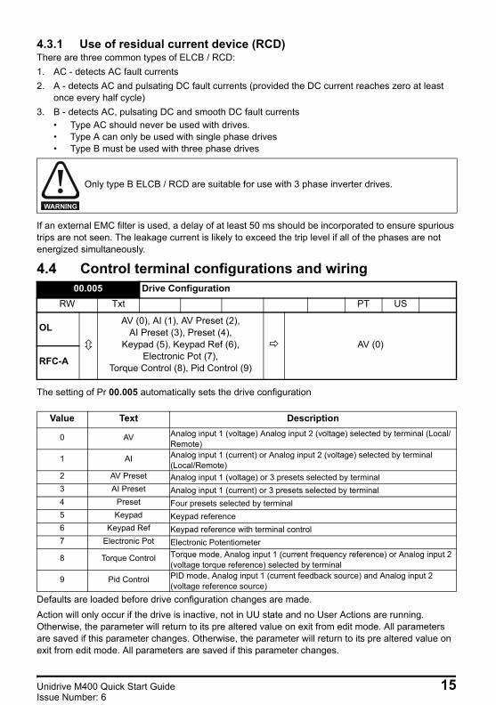
4.4 Control terminal configurations and wiring
The setting of Pr 00.005 automatically sets the drive configuration
Defaults are loaded before drive configuration changes are made. Action will only occur if the drive is inactive, not in UU state and no User Actions are running. Otherwise, the parameter will return to its pre altered value on exit from edit mode. All parameters are saved if this parameter changes. Otherwise, the parameter will return to its pre altered value on exit from edit mode. All parameters are saved if this parameter changes.
Only type B ELCB / RCD are suitable for use with 3 phase inverter drives.
00.005 Drive ConfigurationRW Txt PT US
OLAV (0), AI (1), AV Preset (2),
AI Preset (3), Preset (4), Keypad (5), Keypad Ref (6),
Electronic Pot (7), Torque Control (8), Pid Control (9)
AV (0)
RFC-A
Value Text Description
0 AV Analog input 1 (voltage) Analog input 2 (voltage) selected by terminal (Local/Remote)
1 AI Analog input 1 (current) or Analog input 2 (voltage) selected by terminal (Local/Remote)
2 AV Preset Analog input 1 (voltage) or 3 presets selected by terminal3 AI Preset Analog input 1 (current) or 3 presets selected by terminal4 Preset Four presets selected by terminal5 Keypad Keypad reference6 Keypad Ref Keypad reference with terminal control7 Electronic Pot Electronic Potentiometer
8 Torque Control Torque mode, Analog input 1 (current frequency reference) or Analog input 2 (voltage torque reference) selected by terminal
9 Pid Control PID mode, Analog input 1 (current feedback source) and Analog input 2 (voltage reference source)
WARNING
Unidrive M400 Quick Start Guide 15Issue Number: 6
Unidrive M400 Quick Start Guide English Iss3.book Page 16 Tuesday, September 15, 2015 9:32 AM
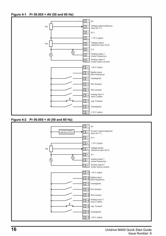
Figure 4-1 Pr 00.005 = AV (50 and 60 Hz)
Figure 4-2 Pr 00.005 = AI (50 and 60 Hz)
1
2
3
4
0V
Voltage speed referenceinput (AI 1+)
AI 1-
Voltage speedreference input (AI 2)
5
6
7
8
0 V
Analog output 1(motor frequency)
+ 10 V output
Analog output 2(motor active current)
9
10
11
Digital output(zero frequency)
Unassigned
12
13
14
15
16
17
Run reverse
Run forward
Analog input 1/input 2 select
+ 24 V output
Jog Forward
Unassigned
+ 24 V output
10k
10k
1
2
3
4
0V
Current speed referenceinput (AI 1+)
AI 1-
Voltage speedreference input (AI 2)
5
6
7
8
0 V
Analog output 1(motor frequency)
+ 10 V output
Analog output 2(motor active current)
9
10
11
Digital output(zero frequency)
Unassigned
12
13
14
15
16
17
Run reverse
Run forward
Analog input 1/input 2 select
+ 24 V output
Jog Forward
Unassigned
+ 24 V output
10k
Current speedreference input
16 Unidrive M400 Quick Start GuideIssue Number: 6
Unidrive M400 Quick Start Guide English Iss3.book Page 17 Tuesday, September 15, 2015 9:32 AM
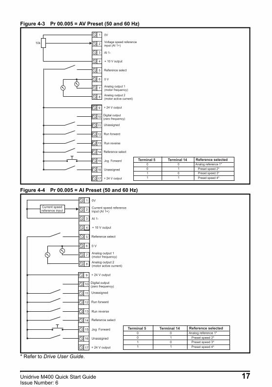
Figure 4-3 Pr 00.005 = AV Preset (50 and 60 Hz)
Figure 4-4 Pr 00.005 = AI Preset (50 and 60 Hz)
* Refer to Drive User Guide.
1
2
3
4
0V
Voltage speed referenceinput (AI 1+)
AI 1-
Reference select5
6
7
8
0 V
Analog output 1(motor frequency)
+ 10 V output
Analog output 2(motor active current)
9
10
11
Digital output(zero frequency)
Unassigned
12
13
14
15
16
17
Run reverse
Run forward
+ 24 V output
Jog Forward
Unassigned
+ 24 V output
10k
Reference select
Terminal 5 Terminal 14 Reference selected
0
0
1
1
0
1
0
1
Analog reference 1*
Preset speed 2*
Preset speed 3*
Preset speed 4*
1
2
3
4
0V
Current speed referenceinput (AI 1+)
AI 1-
Reference select5
6
7
8
0 V
Analog output 1(motor frequency)
+ 10 V output
Analog output 2(motor active current)
9
10
11
Digital output(zero frequency)
Unassigned
12
13
14
15
16
17
Run reverse
Run forward
+ 24 V output
Jog Forward
Unassigned
+ 24 V output
Current speedreference input
Reference select
Terminal 5 Terminal 14 Reference selected
0
0
1
1
0
1
0
1
Analog reference 1*
Preset speed 2*
Preset speed 3*
Preset speed 4*
Unidrive M400 Quick Start Guide 17Issue Number: 6
Unidrive M400 Quick Start Guide English Iss3.book Page 18 Tuesday, September 15, 2015 9:32 AM
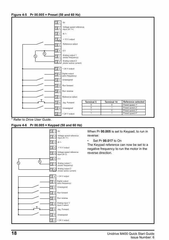
Figure 4-5 Pr 00.005 = Preset (50 and 60 Hz)
* Refer to Drive User Guide.
Figure 4-6 Pr 00.005 = Keypad (50 and 60 Hz)
1
2
3
4
0V
Voltage speed referenceinput (AI 1+)
AI 1-
Reference select5
6
7
8
0 V
Analog output 1(motor frequency)
+ 10 V output
Analog output 2(motor active current)
9
10
11
Digital output(zero frequency)
Unassigned
12
13
14
15
16
17
Reference select
Run forward
+ 24 V output
Jog Forward
Unassigned
+ 24 V output
Run reverse
Terminal 5 Terminal 14 Reference selected
0
0
1
1
0
1
0
1
Preset speed 1*
Preset speed 2*
Preset speed 3*
Preset speed 4*
1
2
3
4
0V
Voltage speed referenceinput (AI 1+)
AI 1-
5
6
7
8
0 V
Analog output 1(motor frequency)
+ 10 V output
Analog output 2(motor active current)
9
10
11
Digital output(zero frequency)
Unassigned
12
13
14
15
16
17
Analog input 1/input 2 select
Run forward
+ 24 V output
Jog Forward
Unassigned
+ 24 V output
Run reverse
Voltage speed referenceinput (AI 2)
When Pr 00.005 is set to Keypad, to run in reverse:• Set Pr 00.017 to OnThe Keypad reference can now be set to a negative frequency to run the motor in the reverse direction.
18 Unidrive M400 Quick Start GuideIssue Number: 6

Unidrive M400 Quick Start Guide English Iss3.book Page 19 Tuesday, September 15, 2015 9:32 AM
Figure 4-7 Pr 00.005 = Keypad Ref (50 and 60 Hz)
Figure 4-8 Pr 00.005 = Electronic Pot (50 and 60 Hz)
1
2
3
4
0V
Voltage speed referenceinput (AI 1+)
AI 1-
5
6
7
8
0 V
Analog output 1(motor frequency)
+ 10 V output
Analog output 2(motor active current)
9
10
11
Digital output(zero frequency)
Unassigned
12
13
14
15
16
17
Analog input 1/input 2 select
Run forward
+ 24 V output
Jog Forward
Unassigned
+ 24 V output
Run reverse
Voltage speed referenceinput (AI 2)
1
2
3
4
0V
Voltage speed referenceinput (AI 1+)
AI 1-
5
6
7
8
0 V
Analog output 1(motor frequency)
+ 10 V output
Analog output 2(motor active current)
9
10
11
Digital output(zero frequency)
Unassigned
12
13
14
15
16
17
UP
Run forward
+ 24 V output
Jog Forward
Unassigned
+ 24 V output
Run reverse
DOWN
When Pr 00.005 is set to Electronic Pot, the following parameters may need to be adjusted:• Motorized pot up/down rate (s/100 %)• Motorized pot bipolar select (0 =
unipolar, 1 = bipolar)• Motorized pot mode: 0 = zero at power-
up, 1 = last value at power-up, 2 = zero at power-up and only change when drive is running, 3 = last value at power-up and only change when drive is running, 4 = zero at power-up and drive disabled, only change when drive is running.
Unidrive M400 Quick Start Guide 19Issue Number: 6

Unidrive M400 Quick Start Guide English Iss3.book Page 20 Tuesday, September 15, 2015 9:32 AM
Figure 4-9 Pr 00.005 = Torque Control (50 and 60 Hz)
Figure 4-10 Pr 00.005 = PID Control (50 and 60 Hz)
1
2
3
4
0V
Current speed referenceinput (AI 1+)
AI 1-
Torque referenceinput (AI 2)
5
6
7
8
0 V
Analog output 1(motor frequency)
+ 10 V output
Analog output 2(motor active current)
9
10
11
Digital output(zero frequency)
Unassigned
12
13
14
15
16
17
Run reverse
Run forward
Torque mode select
+ 24 V output
Jog Forward
Unassigned
+ 24 V output
10k
Current speedreference input
When torque mode is selected and the drive is connected to an unloaded motor, the motor speed may increase rapidly to the maximum speed (Pr 00.002 +10 %)
WARNING
1
2
3
4
0V
PID feedbackinput (AI 1+)
AI 1-
5
6
7
8
0 V
Analog output 1(motor frequency)
+ 10 V output
Analog output 2(motor active current)
9
10
11
Digital output(zero frequency)
Unassigned
12
13
14
15
16
17
Run reverse
Run forward
PID enable
+ 24 V output
Jog Forward
Unassigned
+ 24 V output
4-20 mA PIDfeedback input
0-10 V PIDreference input
PID referenceinput (AI 2)
When Pr 00.005 is set to Pid, the following parameters may need to be adjusted:• PID proportional gain• PID integral gain• PID feedback invert• PID output upper limit (%)• PID output lower limit (%)
20 Unidrive M400 Quick Start GuideIssue Number: 6

Unidrive M400 Quick Start Guide English Iss3.book Page 21 Tuesday, September 15, 2015 9:32 AM
4.5 EMC4.5.1 Internal EMC filterIt is recommended that the internal EMC filter be kept in place unless there is a specific reason for removing it. If the drive is used as a motoring drive as part of a regen system, then the internal EMC filter must be removed.The internal EMC filter reduces radio-frequency emission into the line power supply.For longer motor cables, the filter continues to provide a useful reduction in emission levels and when used with any length of shielded motor cable up to the limit for the drive, it is unlikely that nearby industrial equipment will be disturbed. It is recommended that the filter be used in all applications unless the instructions given above require it to be removed, or where the ground leakage current is unacceptable.
4.5.2 Removing the internal EMC filter
Figure 4-11 Removal of the internal EMC filter (size 2 shown)
To electrically disconnect the internal EMC filter, remove the screw as shown above (1).
4.5.3 Further EMC precautionsFurther EMC precautions are required if more stringent EMC emission requirements apply:• Operation in the first environment of EN 61800-3: 2004• Conformity to the generic emission standards• Equipment which is sensitive to electrical interference operating nearbyIn this case it is necessary to use:• The optional external EMC filter• A shielded motor cable, with shield clamped to the grounded metal panel
The supply must be disconnected before removing the internal EMC filter.
WARNING
1
Unidrive M400 Quick Start Guide 21Issue Number: 6
Unidrive M400 Quick Start Guide English Iss3.book Page 22 Tuesday, September 15, 2015 9:32 AM
• A shielded control cable, with shield clamped to the grounded metal panelFull instructions are given in the Drive User Guide.A full range of external EMC filters are also available for use with Unidrive M400.
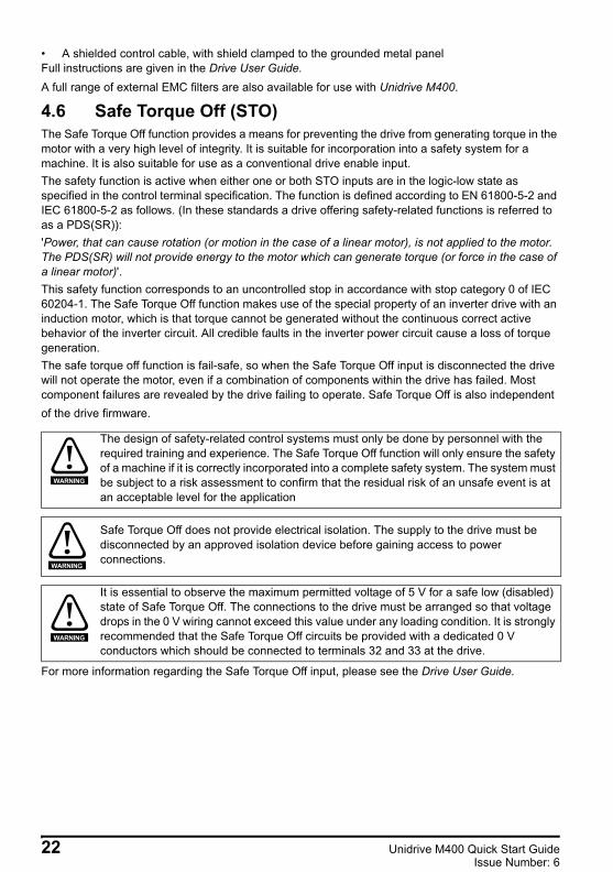
4.6 Safe Torque Off (STO) The Safe Torque Off function provides a means for preventing the drive from generating torque in the motor with a very high level of integrity. It is suitable for incorporation into a safety system for a machine. It is also suitable for use as a conventional drive enable input.The safety function is active when either one or both STO inputs are in the logic-low state as specified in the control terminal specification. The function is defined according to EN 61800-5-2 and IEC 61800-5-2 as follows. (In these standards a drive offering safety-related functions is referred to as a PDS(SR)): 'Power, that can cause rotation (or motion in the case of a linear motor), is not applied to the motor. The PDS(SR) will not provide energy to the motor which can generate torque (or force in the case of a linear motor)'.This safety function corresponds to an uncontrolled stop in accordance with stop category 0 of IEC 60204-1. The Safe Torque Off function makes use of the special property of an inverter drive with an induction motor, which is that torque cannot be generated without the continuous correct active behavior of the inverter circuit. All credible faults in the inverter power circuit cause a loss of torque generation.The safe torque off function is fail-safe, so when the Safe Torque Off input is disconnected the drive will not operate the motor, even if a combination of components within the drive has failed. Most component failures are revealed by the drive failing to operate. Safe Torque Off is also independent of the drive firmware.
For more information regarding the Safe Torque Off input, please see the Drive User Guide.
The design of safety-related control systems must only be done by personnel with the required training and experience. The Safe Torque Off function will only ensure the safety of a machine if it is correctly incorporated into a complete safety system. The system must be subject to a risk assessment to confirm that the residual risk of an unsafe event is at an acceptable level for the application
Safe Torque Off does not provide electrical isolation. The supply to the drive must be disconnected by an approved isolation device before gaining access to power connections.
It is essential to observe the maximum permitted voltage of 5 V for a safe low (disabled) state of Safe Torque Off. The connections to the drive must be arranged so that voltage drops in the 0 V wiring cannot exceed this value under any loading condition. It is strongly recommended that the Safe Torque Off circuits be provided with a dedicated 0 V conductors which should be connected to terminals 32 and 33 at the drive.
WARNING
WARNING
WARNING
22 Unidrive M400 Quick Start GuideIssue Number: 6

Unidrive M400 Quick Start Guide English Iss3.book Page 23 Tuesday, September 15, 2015 9:32 AM
5 Optional LCD keypad and displayThe keypad and display provide information to the user regarding the operating status of the drive and trip codes, and provide the means for changing parameters, stopping and starting the drive, and the ability to perform a drive reset.Figure 5-1 Unidrive M400 keypad detail
(1) The Enter button is used to enter parameter view or edit mode, or to accept a parameter edit. (2) The Navigation keys can be used to select individual parameters or to edit parameter values. In
keypad mode, the ‘Up’ and ‘Down’ keys are also used to increase or decrease the motor speed.(3) The Start key is used to start the drive in keypad mode.(4) The Stop / Reset key is used to stop and reset the drive in keypad mode. It can also be used to
reset the drive in terminal mode.(5) The Escape key is used to exit from the parameter edit / view mode or disregard a parameter edit.
Table 5-1 Status indications
The keypad is not supplied with the drive.
It is possible to display alternative parameters on the multi line LCD display such as current magnitude. Refer to the Drive User Guide for further information.
Upper rowstring Description Drive output
stage
Inhibit The drive is inhibited and cannot be run. The Safe Torque Off signals are not applied to the Safe Torque Off terminals is set to 0. Disabled
Ready The drive is ready to run. The drive enable is active, but the drive inverter is not active because the final drive run is not active. Disabled
Stop The drive is stopped / holding zero frequency. EnabledRun The drive is active and running. Enabled
Supply Loss Supply loss condition has been detected Enabled
Deceleration The motor is being decelerated to zero frequency because the final drive run has been deactivated. Enabled
dc Injection The drive is applying DC injection braking. Enabled
Trip The drive has tripped and no longer controlling the motor. The trip code appears in the lower display. Disabled
Under Voltage
The drive is in the under voltage state either in low voltage or high voltage mode. Disabled
5 1
4
2
3
NOTE
NOTE
Unidrive M400 Quick Start Guide 23Issue Number: 6

Unidrive M400 Quick Start Guide English Iss3.book Page 24 Tuesday, September 15, 2015 9:32 AM
5.1 Saving parametersWhen changing a parameter in Menu 0, the new value is saved when pressing the Enter button
to return to parameter view mode from parameter edit mode.
If parameters have been changed in the advanced menus, then the change will not be saved automatically. A save function must be carried out.
Procedure1. Select ‘Save parameters'* in Pr mm.000 (alternatively enter a value of 1001* in Pr mm.000)2. Either:
• Press the red reset button• Carry out a drive reset through serial communications by setting Pr 10.038 to 100 * If the drive is in the under voltage state (i.e. when the AI-Backup adaptor terminals are being supplied from a +24 Vdc supply) a value of 1001 must be entered into Pr mm.000 to perform a save function.
5.2 Restoring parameter defaultsRestoring parameter defaults by this method saves the default values in the drives memory. User security status (00.010) and User security code (00.025) are not affected by this procedure).
Procedure1. Ensure the drive is not enabled, i.e. terminal 31 & 34 is open or is OFF (0)2. Select 'Reset 50 Hz Defs’ or 'Reset 60 Hz Defs' in Pr mm.000. (alternatively, enter 1233 (50 Hz
settings) or 1244 (60 Hz settings) in Pr mm.000).3. Either:
• Press the red reset button• Carry out a drive reset through serial communications by setting Pr 10.038 to 100
24 Unidrive M400 Quick Start GuideIssue Number: 6
Unidrive M400 Quick Start Guide English Iss3.book Page 25 Tuesday, September 15, 2015 9:32 AM
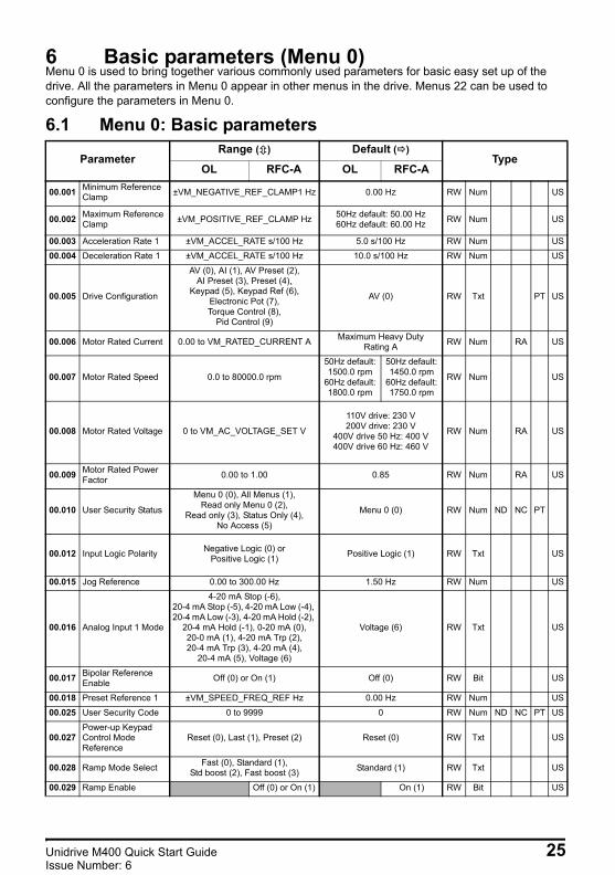
6 Basic parameters (Menu 0)Menu 0 is used to bring together various commonly used parameters for basic easy set up of the drive. All the parameters in Menu 0 appear in other menus in the drive. Menus 22 can be used to configure the parameters in Menu 0.
6.1 Menu 0: Basic parameters
ParameterRange ( ) Default ( )
TypeOL RFC-A OL RFC-A
00.001 Minimum Reference Clamp ±VM_NEGATIVE_REF_CLAMP1 Hz 0.00 Hz RW Num US
00.002 Maximum Reference Clamp ±VM_POSITIVE_REF_CLAMP Hz 50Hz default: 50.00 Hz
60Hz default: 60.00 Hz RW Num US
00.003 Acceleration Rate 1 ±VM_ACCEL_RATE s/100 Hz 5.0 s/100 Hz RW Num US00.004 Deceleration Rate 1 ±VM_ACCEL_RATE s/100 Hz 10.0 s/100 Hz RW Num US
00.005 Drive Configuration
AV (0), AI (1), AV Preset (2), AI Preset (3), Preset (4),
Keypad (5), Keypad Ref (6), Electronic Pot (7), Torque Control (8),
Pid Control (9)
AV (0) RW Txt PT US
00.006 Motor Rated Current 0.00 to VM_RATED_CURRENT A Maximum Heavy Duty Rating A RW Num RA US
00.007 Motor Rated Speed 0.0 to 80000.0 rpm
50Hz default: 1500.0 rpm
60Hz default: 1800.0 rpm
50Hz default: 1450.0 rpm
60Hz default: 1750.0 rpm
RW Num US
00.008 Motor Rated Voltage 0 to VM_AC_VOLTAGE_SET V
110V drive: 230 V200V drive: 230 V
400V drive 50 Hz: 400 V400V drive 60 Hz: 460 V
RW Num RA US
00.009 Motor Rated Power Factor 0.00 to 1.00 0.85 RW Num RA US
00.010 User Security Status
Menu 0 (0), All Menus (1), Read only Menu 0 (2),
Read only (3), Status Only (4), No Access (5)
Menu 0 (0) RW Num ND NC PT
00.012 Input Logic Polarity Negative Logic (0) orPositive Logic (1) Positive Logic (1) RW Txt US
00.015 Jog Reference 0.00 to 300.00 Hz 1.50 Hz RW Num US
00.016 Analog Input 1 Mode
4-20 mA Stop (-6), 20-4 mA Stop (-5), 4-20 mA Low (-4), 20-4 mA Low (-3), 4-20 mA Hold (-2),
20-4 mA Hold (-1), 0-20 mA (0), 20-0 mA (1), 4-20 mA Trp (2), 20-4 mA Trp (3), 4-20 mA (4),
20-4 mA (5), Voltage (6)
Voltage (6) RW Txt US
00.017 Bipolar Reference Enable Off (0) or On (1) Off (0) RW Bit US
00.018 Preset Reference 1 ±VM_SPEED_FREQ_REF Hz 0.00 Hz RW Num US
00.025 User Security Code 0 to 9999 0 RW Num ND NC PT US
00.027Power-up Keypad Control Mode Reference
Reset (0), Last (1), Preset (2) Reset (0) RW Txt US
00.028 Ramp Mode Select Fast (0), Standard (1), Std boost (2), Fast boost (3) Standard (1) RW Txt US
00.029 Ramp Enable Off (0) or On (1) On (1) RW Bit US
Unidrive M400 Quick Start Guide 25Issue Number: 6

Unidrive M400 Quick Start Guide English Iss3.book Page 26 Tuesday, September 15, 2015 9:32 AM
00.030 Parameter Cloning None (0), Read (1), Program (2), Auto (3), Boot (4) None (0) RW Txt NC US
00.031 Stop Mode
Coast (0), Ramp (1),
Ramp dc I (2), dc I (3),
Timed dc I (4), Disable (5)
Coast (0), Ramp (1),
Ramp dc I (2), dc I (3),
Timed dc I (4), Disable (5),
No Ramp (6)
Ramp (1) RW Txt US
00.032Dynamic V to F Select / Flux Optimization Select
0 to 1 0 RW Num US
00.033 Catch A Spinning Motor
Disable (0), Enable (1), Fwd Only (2), Rev Only (3) Disable (0) RW Txt US
00.034 Digital Input 5 Mode Input (0), Therm Short Cct (1), Thermistor (2), Therm No Trip (3) Input (0) RW Txt US
00.035 Digital Output 1 Control 0 to 21 0 RW Num US
00.036 Analog Output 1 Control 0 to 14 0 RW Txt US
00.037 Maximum Switching Frequency
0.667 (0), 1 (1), 2 (2), 3 (3), 4 (4), 6 (5), 8 (6), 12 (7),
16 (8) kHz
2 (2), 3 (3), 4 (4), 6 (5),8 (6), 12 (7), 16 (8) kHz
3 (3) kHz RW Txt US
00.038 Autotune 0 to 2 0 to 3 0 RW Num NC US
00.039 Motor Rated Frequency
0.00 to VM_SPEED_FREQ_REF_UNIPOLAR Hz
50Hz: 50.00 Hz60Hz: 60.00 Hz RW Num US
00.040 Number of Motor Poles* Auto (0) to 32 (16) Auto 0 RW Num US
00.041 Control Mode
Ur S (0), Ur (1), Fixed (2),
Ur Auto (3), Ur I (4),
Square (5), Fixed Tapered (6)
UrI (4) RW Txt US
00.042 Low Frequency Voltage Boost 0.0 to 25.0 % 3.0 % RW Num US
00.043 Serial Baud Rate
300 (0), 600 (1), 1200 (2), 2400 (3), 4800 (4), 9600 (5),
19200 (6), 38400 (7), 57600 (8), 76800 (9), 115200 (10)
19200 (6) RW Txt US
00.044 Serial Address 1 to 247 1 RW Num US
00.045 Reset Serial Communications Off (0) or On (1) Off (0) RW ND NC US
00.046Brake Controller Upper Current Threshold
0 to 200 % 50 % RW Num US
00.047Brake Controller Lower Current Threshold
0 to 200 % 10 % RW Num US
00.048Brake Controller Brake Release Frequency
0.00 to 20.00 Hz 1.00 Hz RW Num US
00.049Brake Controller Brake Apply Frequency
0.00 to 20.00 Hz 2.00 Hz RW Num US
00.050 Brake Controller Brake Delay 0.0 to 25.0 s 1.0 s RW Num US
00.051Brake Controller Post-brake Release Delay
0.0 to 25.0 s 1.0 s RW Num US
ParameterRange ( ) Default ( )
TypeOL RFC-A OL RFC-A
26 Unidrive M400 Quick Start GuideIssue Number: 6

Unidrive M400 Quick Start Guide English Iss3.book Page 27 Tuesday, September 15, 2015 9:32 AM
* If this parameter is read via serial communications, it will show pole pairs.
00.053 Brake Controller Initial Direction Ref (0), Forward (1), Reverse (2) Ref (0) RW Txt US
00.054Brake Controller Brake Apply Through Zero Threshold
0.00 to 25.00 Hz 0.00 Hz RW Num US
00.055 Brake Controller Enable
Disable (0), Relay (1), Digital IO (2), User (3) Disable (0) RW Txt US
00.059 OUP Enable Stop (0) or Run (1) Run (1) RW Txt US
00.065Frequency Controller Proportional Gain Kp1
0.000 to 200.000 s/rad 0.100 s/rad RW Num US
00.066 Frequency Controller Integral Gain Ki1
0.00 to 655.35 s2/rad 0.10 s2/rad RW Num US
00.067 Sensorless Mode Filter
4 (0), 5 (1), 6 (2), 8 (3), 12 (4),
20 (5) ms4 (0) ms RW Txt US
00.069 Spin Start Boost 0.0 to 10.0 1.0 RW Num US
00.076 Action on Trip Detection 0 to 31 0 RW Num ND NC PT US
00.077 Maximum Heavy Duty Current Rating 0.00 to 9999.99 A RO Num ND NC PT
00.078 Software Version 0 to 999999 RO Num ND NC PT
00.079 User Drive Mode Open loop (1), RFC A (2) Open loop (1) RFC-A (2) RW Txt ND NC PT US
RW Read / Write RO Read
only Num Number parameter Bit Bit
parameter Txt Text string Bin Binary parameter FI Filtered
NDNo default value
NC Not copied PT Protected
parameter RA Rating dependent US User save PS Power-down
save DE Destination
ParameterRange ( ) Default ( )
TypeOL RFC-A OL RFC-A
Unidrive M400 Quick Start Guide 27Issue Number: 6
Unidrive M400 Quick Start Guide English Iss3.book Page 28 Tuesday, September 15, 2015 9:32 AM
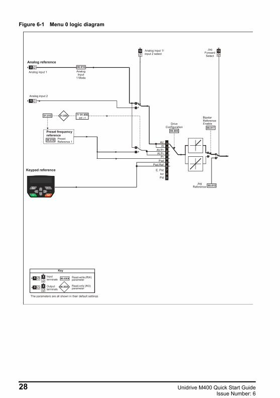
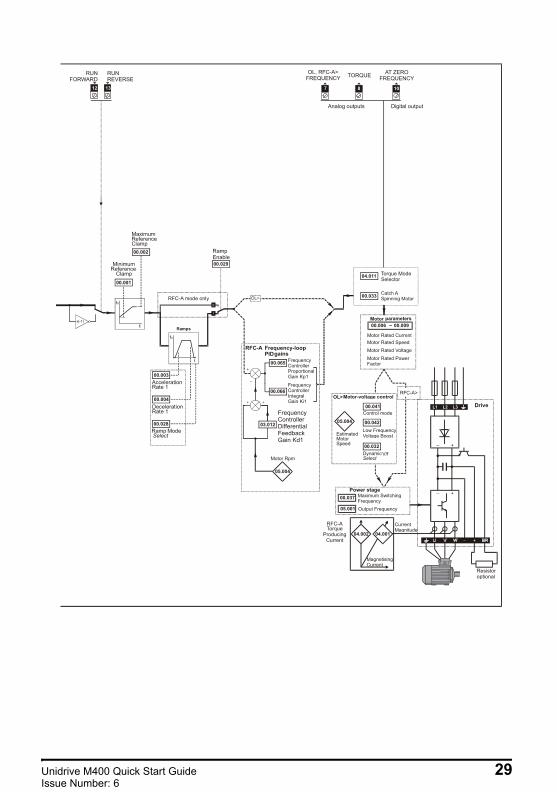
Figure 6-1 Menu 0 logic diagram
2
5
Analog reference
Keypad reference
00.XXX
00.XXX
Key
Read-write (RW)parameter
Read-only (RO)parameter
Inputterminals
Outputterminals
XX
XX
The parameters are all shown in their default settings
00.018 PresetReference 1
Preset frequencyreference
14
0
5
00.017
00.015
Bipolar
Analog input 1 AnalogInput
1 Mode
15JogForwardSelect
JogReference
Analog input 1/input 2 select
Analog input 2
ReferenceEnable
AV
PrPad
Pad.Ref
E. PottorPid
6789
01.015 Prset01.050
>101.050
00.005
DriveConfiguration
AIAV.PrAI.Pr
1234
00.016
28 Unidrive M400 Quick Start GuideIssue Number: 6
Unidrive M400 Quick Start Guide English Iss3.book Page 29 Tuesday, September 15, 2015 9:32 AM
FrequencyControllerProportionalGain Kp1
FrequencyControllerIntegralGain Ki1
Motor Rpm
00.065
00.066
FrequencyControllerDifferentialFeedbackGain Kd1
RFC-A Frequency-loopPIDgains
7 108
AT ZEROFREQUENCY
Motor Rated CurrentMotor Rated SpeedMotor Rated VoltageMotor Rated PowerFactor
00.006 ~ 00.009Motor parameters
Power stage
Control mode
DynamicV/fSelect
Low FrequencyVoltage Boost
OL>Motor-voltage control
EstimatedMotorSpeed
_ +
_ +
U V W
Resistoroptional
Drive
RUNREVERSE
RUNFORWARD
MinimumReference
Reference
Clamp00.001
00.002
12 13
Ramps
AccelerationRate 1
DecelerationRate 1
Ramp ModeSelect
00.003
00.004
00.028
RFC-A mode only
00.029
Maximum
ClampRampEnable
Analog outputs
TORQUE
Digital output
00.037
05.001
Maximum SwitchingFrequencyOutput Frequency
00.033
04.011 Torque ModeSelector
RFC-ATorque
ProducingCurrent
CurrentMagnitude
MagnetisingCurrent
+ BR_
RFC-A>
OL, RFC-A>FREQUENCY
04.002 04.001
00.041
00.04205.004
05.004
03.012
00.032
L3L2L1
Unidrive M400 Quick Start Guide 29Issue Number: 6

Unidrive M400 Quick Start Guide English Iss3.book Page 30 Tuesday, September 15, 2015 9:32 AM
6.2 Unidrive M400 parameter descriptionsKey:
Set Pr 00.001 at the required minimum output frequency of the drive for both directions of rotation. The drive speed reference is scaled between Pr 00.001 and Pr 00.002. Pr 00.001 is a nominal value; slip compensation may cause the actual frequency to be higher. When the drive is jogging, Pr 00.001 has no effect.
Set Pr 00.002 at the required maximum output frequency for both directions of rotation. The drive speed reference is scaled between Pr 00.001 and Pr 00.002. Pr 00.002 is a nominal value; slip compensation may cause the actual frequency to be higher. The drive has additional over-speed protection.
Set Pr 00.003 at the required rate of acceleration. Note that larger values produce lower acceleration. The rate applies in both directions of rotation.
RW Read / Write RO Read
only Num Number parameter Bit Bit
parameter Txt Text string Bin Binary parameter FI Filtered
NDNo default value
NC Not copied PT Protected
parameter RA Rating dependent US User save PS Power-down
save DE Destination
00.001 01.007 Minimum Reference ClampRW Num US
OL±VM_NEGATIVE_REF_CLAMP1 Hz 0.00 Hz
RFC-A
00.002 01.006 Maximum Reference ClampRW Num US
OL±VM_POSITIVE_REF_CLAMP Hz 50.0 Hz default: 50.00 Hz
60.0 Hz default: 60.00 HzRFC-A
00.003 02.011 Acceleration Rate 1RW Num US
OL±VM_ACCEL_RATE s/100 Hz 5.0 s/100 Hz
RFC-A
30 Unidrive M400 Quick Start GuideIssue Number: 6

Unidrive M400 Quick Start Guide English Iss3.book Page 31 Tuesday, September 15, 2015 9:32 AM
Set Pr 00.004 at the required rate of deceleration. Note that larger values produce lower deceleration. The rate applies in both directions of rotation.
Use Pr 00.005 to select the required frequency/speed reference as follows:
00.004 02.021 Deceleration Rate 1RW Num US
OL±VM_ACCEL_RATE s/100 Hz 10.0 s/100 Hz
RFC-A
00.005 11.034 Drive Configuration RW Txt PT US
OL
AV (0), AI (1), AV Preset (2), AI Preset (3), Preset (4),
Keypad (5), Keypad Ref (6), Electronic Pot (7),
Torque Control (8), Pid Control (9)
AV (0)
Value Text Description
0 AV Analog input 1 (voltage) Analog input 2 (voltage) selected by terminal (Local/Remote)
1 AI Analog input 1 (current) or Analog input 2 (voltage) selected by terminal (Local/Remote)
2 AV Preset Analog input 1 (voltage) or 3 presets selected by terminal3 AI Preset Analog input 1 (current) or 3 presets selected by terminal4 Preset Four presets selected by terminal5 Keypad Keypad reference6 Keypad Ref Keypad reference with terminal control7 Electronic Pot Electronic Potentiometer
8 Torque Control Torque mode, Analog input 1 (current frequency reference) or Analog input 2 (voltage torque reference) selected by terminal
9 Pid Control PID mode, Analog input 1 (current feedback source) and Analog input 2 (voltage reference source)
A change to Pr 00.005 is set by pressing the MODE key on exit from parameter edit mode. The drive must be disabled, stopped or tripped for a change to take place. If Pr 00.005 is changed while the drive is running, when the MODE key is pressed on exit from parameter edit mode, Pr 00.005 will change back to its previous value.
When the setting of Pr 00.005 is changed, the appropriate drive configuration parameters are set back to their default values.
NOTE
NOTE
Unidrive M400 Quick Start Guide 31Issue Number: 6
Unidrive M400 Quick Start Guide English Iss3.book Page 32 Tuesday, September 15, 2015 9:32 AM
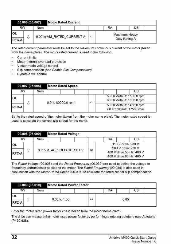
The rated current parameter must be set to the maximum continuous current of the motor (taken from the name plate). The motor rated current is used in the following:• Current limits • Motor thermal overload protection • Vector mode voltage control• Slip compensation (see Enable Slip Compensation)• Dynamic V/F control
Set to the rated speed of the motor (taken from the motor name plate). The motor rated speed is used to calculate the correct slip speed for the motor.
The Rated Voltage (00.008) and the Rated Frequency (00.039) are used to define the voltage to frequency characteristic applied to the motor. The Rated Frequency (00.039) is also used in conjunction with the Motor Rated Speed (00.007) to calculate the rated slip for slip compensation.
Enter the motor rated power factor cos ϕ (taken from the motor name plate).
The drive can measure the motor rated power factor by performing a rotating autotune (see Autotune (Pr 00.038).
00.006 05.007 Motor Rated CurrentRW Num RA US
OL0.00 to VM_RATED_CURRENT A Maximum Heavy
Duty Rating ARFC-A
00.007 05.008 Motor Rated SpeedRW Num US
OL0.0 to 80000.0 rpm
50 Hz default: 1500.0 rpm60 Hz default: 1800.0 rpm
RFC-A 50 Hz default: 1450.0 rpm60 Hz default: 1750.0rpm
00.008 05.009 Motor Rated VoltageRW Num RA US
OL0 to VM_AC_VOLTAGE_SET V
110 V drive: 230 V200 V drive: 230 V
400 V drive 50 Hz: 400 V400 V drive 60 Hz: 460 V
RFC-A
00.009 05.010 Motor Rated Power FactorRW Num RA US
OL0.00 to 1.00 0.85
RFC-A
32 Unidrive M400 Quick Start GuideIssue Number: 6

Unidrive M400 Quick Start Guide English Iss3.book Page 33 Tuesday, September 15, 2015 9:32 AM
This parameter controls access via the drive keypad as follows:
Defines the reference when jog is enabled.
Can be set to zero to change the logic for DI/O1-7 to negative logic, so that the state parameter is 0 if the digital I/O is high or 1 if the digital I/O is low.
00.010 11.044 User Security StatusRW Num ND NC PT US
OL Menu 0 (0), All Menus (1), Read only Menu 0 (2), Read only (3),
Status Only (4), No Access (5)Menu 0 (0)
RFC-A
Value Text Function
0 Menu 0 All writable parameters are available to be edited but only parameters in Menu 0 are visible.
1 All Menus All writable parameters are visible and available to be edited.2 Read-only Menu 0 All parameters are read-only. Access is limited to Menu 0 parameters only.3 Read-only All parameters are read-only however all menus and parameters are visible.
4 Status Only The keypad remains in status mode and no parameters can be viewed or edited.
5 No Access The keypad remains in status mode and no parameters can be viewed or edited. Drive parameters cannot be accessed via a comms/fieldbus interface in the drive or any option module.
00.015 01.005 Jog ReferenceRW Num US
OL0.00 to 300.00 Hz 1.50 Hz
RFC-A
00.012 08.010 Input Logic PolarityRW Txt US
OL Negative Logic (0) orPositive Logic (1) Positive Logic (1)
RFC-A
Unidrive M400 Quick Start Guide 33Issue Number: 6
Unidrive M400 Quick Start Guide English Iss3.book Page 34 Tuesday, September 15, 2015 9:32 AM
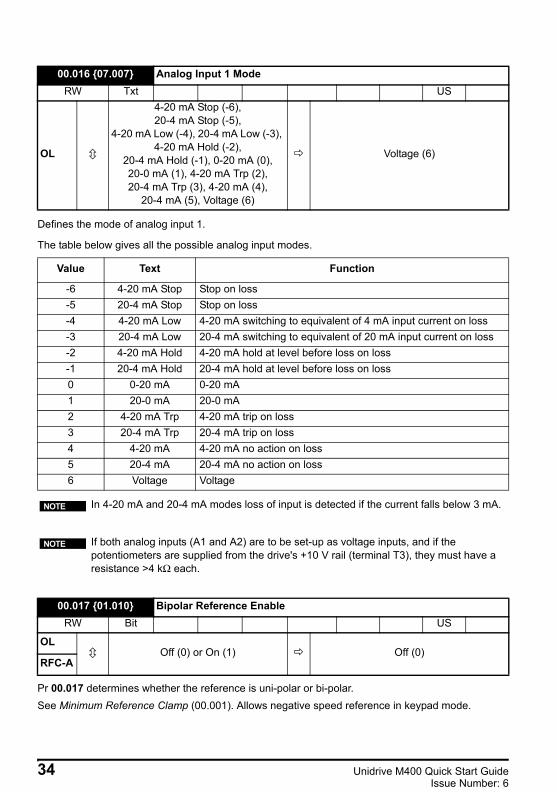
Defines the mode of analog input 1.
The table below gives all the possible analog input modes.
Pr 00.017 determines whether the reference is uni-polar or bi-polar.See Minimum Reference Clamp (00.001). Allows negative speed reference in keypad mode.
00.016 07.007 Analog Input 1 ModeRW Txt US
OL
4-20 mA Stop (-6), 20-4 mA Stop (-5),
4-20 mA Low (-4), 20-4 mA Low (-3), 4-20 mA Hold (-2),
20-4 mA Hold (-1), 0-20 mA (0), 20-0 mA (1), 4-20 mA Trp (2), 20-4 mA Trp (3), 4-20 mA (4),
20-4 mA (5), Voltage (6)
Voltage (6)
Value Text Function
-6 4-20 mA Stop Stop on loss-5 20-4 mA Stop Stop on loss-4 4-20 mA Low 4-20 mA switching to equivalent of 4 mA input current on loss-3 20-4 mA Low 20-4 mA switching to equivalent of 20 mA input current on loss-2 4-20 mA Hold 4-20 mA hold at level before loss on loss-1 20-4 mA Hold 20-4 mA hold at level before loss on loss0 0-20 mA 0-20 mA 1 20-0 mA 20-0 mA2 4-20 mA Trp 4-20 mA trip on loss3 20-4 mA Trp 20-4 mA trip on loss4 4-20 mA 4-20 mA no action on loss5 20-4 mA 20-4 mA no action on loss6 Voltage Voltage
In 4-20 mA and 20-4 mA modes loss of input is detected if the current falls below 3 mA.
If both analog inputs (A1 and A2) are to be set-up as voltage inputs, and if the potentiometers are supplied from the drive's +10 V rail (terminal T3), they must have a resistance >4 kΩ each.
00.017 01.010 Bipolar Reference EnableRW Bit US
OLOff (0) or On (1) Off (0)
RFC-A
NOTE
NOTE
34 Unidrive M400 Quick Start GuideIssue Number: 6

Unidrive M400 Quick Start Guide English Iss3.book Page 35 Tuesday, September 15, 2015 9:32 AM
If the preset reference has been selected (see Pr 00.005), the speed at which the motor runs is determined by these parameters.See Drive Configuration (00.005).
If any number other than 0 is programmed into this parameter, user security can be applied so that no parameters except Pr 00.010 can be adjusted with the keypad. When this parameter is read via a keypad it appears as zero. Refer to the Drive User Guide for further information.
Defines which value of keypad control mode reference is displayed at power-up.
Defines the mode used by the ramp system.0: Fast ramp1: Standard ramp2: Standard ramp with motor voltage boost
00.018 01.021 Preset Reference 1RW Num US
OL±VM_SPEED_FREQ_REF Hz 0.00 Hz
RFC-A
00.025 11.030 User Security CodeRW Num ND NC PT US
OL0-9999 0
RFC-A
00.027 01.051 Power-up Keypad Control Mode ReferenceRW Txt ND NC PT US
OLReset (0), Last (1), Preset (2) Reset (0)
RFC-A
Value Text Description0 Reset Keypad reference is zero1 Last Keypad reference is the last used value2 Preset Keypad reference is copied from Preset Reference 1 (00.018)
00.028 02.004 Ramp Mode SelectRW Txt US
OL Fast (0), Standard (1), Std boost (2), Fast boost (3) Standard (1)
RFC-A
Unidrive M400 Quick Start Guide 35Issue Number: 6

Unidrive M400 Quick Start Guide English Iss3.book Page 36 Tuesday, September 15, 2015 9:32 AM
3: Fast ramp with motor voltage boostFast ramp is linear deceleration at programmed rate, normally used when a braking resistor is installed.Standard ramp is controlled deceleration to prevent DC bus over-voltage trips, normally used when there is no braking resistor installed.If a high motor voltage mode is selected, deceleration rates can be faster for a given inertia but motor temperatures will be higher.
Setting Pr 00.029 to 0 allows the user to disable the ramps. This is generally used when the drive is required to closely follow a speed reference which already contains acceleration and deceleration ramps.
* Only a value of 3 or 4 in this parameter is saved.If Pr 00.030 is equal to 1 or 2, this value is not transferred to the EEPROM or the drive. If Pr 00.030 is set to a 3 or 4 the value is transferred.
For further information, please refer to Chapter 8 Diagnostics on page 50.
00.029 02.002 Ramp EnableRW Bit US
OL
RFC-A Off (0) or On (1) On (1)
00.030 11.042 Parameter CloningRW Txt NC US*
OL None (0), Read (1), Program (2), Auto (3), Boot (4) None (0)
RFC-A
Parameter string Parameter value CommentNone 0 InactiveRead 1 Read parameter set from the NV Media Card
Program 2 Programming a parameter set to the NV Media CardAuto 3 Auto saveBoot 4 Boot mode
36 Unidrive M400 Quick Start GuideIssue Number: 6

Unidrive M400 Quick Start Guide English Iss3.book Page 37 Tuesday, September 15, 2015 9:32 AM
Defines how the motor is controlled when the run signal is removed from the drive.
See the Drive User Guide for further information.
Set to 1 to enable Dynamic V to F mode.0: Fixed linear voltage to frequency ratio (constant torque - standard load)1: Voltage to frequency ratio dependant on load current. This gives a higher motor efficiency.
00.031 06.001 Stop ModeRW Txt US
OLCoast (0), Ramp (1),
Ramp dc I (2), dc I (3), Timed dc I (4), Disable (5)
Ramp (1)
RFC-A
Coast (0), Ramp (1), Ramp dc I (2), dc I (3),
Timed dc I (4), Disable (5), No Ramp (6)
Value Text Description0 Coast Coast stop1 Ramp Ramp stop2 Ramp dc I Ramp stop + 1 second dc injection3 dc I Injection braking stop with detection of zero speed4 Timed dc I Timed injection braking stop5 Disable Disable6 No Ramp No ramp (RFC-A mode only)
00.032 05.013 Dynamic V To F Select / Flux Optimisation SelectRW Num US
OL0 to 1 0
RFC-A
Unidrive M400 Quick Start Guide 37Issue Number: 6

Unidrive M400 Quick Start Guide English Iss3.book Page 38 Tuesday, September 15, 2015 9:32 AM
If the drive is to be configured in fixed boost mode (Pr 00.041 = Fd or SrE) with catch a spinning motor software enabled, an autotune (see Pr 00.038 on page 41) must be carried out to measure the motor's stator resistance beforehand. If a stator resistance is not measured, the drive may trip on 0 V or OI.AC while trying to catch a spinning motor.
This parameter selects the function of Digital Input 5.
00.033 06.009 Catch a Spinning MotorRW Txt US
OL Disable (0), Enable (1), Fwd Only (2), Rev Only (3) Disable (0)
RFC-A
Pr 00.033 Text Function0 Disable Disabled1 Enable Detect all frequencies2 Fwd Only Detect positive frequencies only3 Rev Only Detect negative frequencies only
00.034 08.035 Digital Input 5 ModeRW Txt US
OL Input (0), Therm Short Cct (1), Thermistor (2), Therm No Trip (3) Input (0)
RFC-A
Value Text Function0 Input Digital input
1 Therm Short Cct Temperature measurement input with short circuit detection(Resistance <50 Ω )
2 Thermistor Temperature measurement input without short circuit detection but with th trip
3 Therm No Trip Temperature measurement input with no trips
38 Unidrive M400 Quick Start GuideIssue Number: 6
Unidrive M400 Quick Start Guide English Iss3.book Page 39 Tuesday, September 15, 2015 9:32 AM
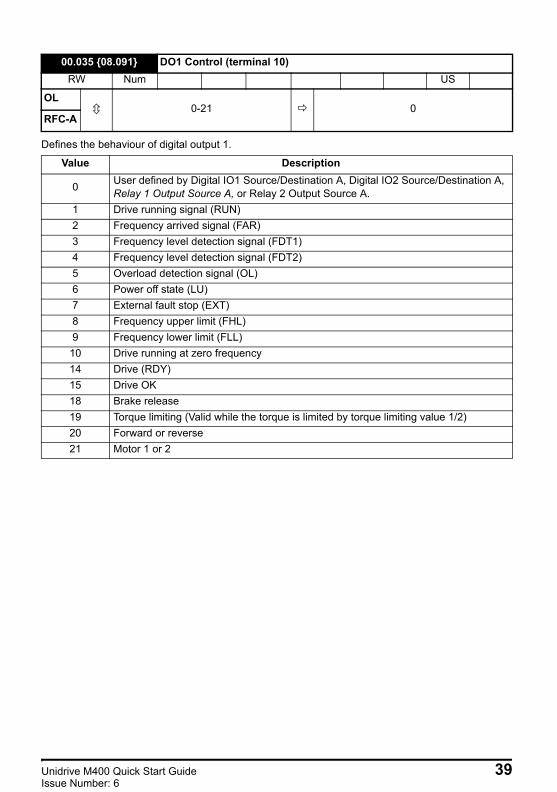
Defines the behaviour of digital output 1.
00.035 08.091 DO1 Control (terminal 10)RW Num US
OL0-21 0
RFC-A
Value Description
0 User defined by Digital IO1 Source/Destination A, Digital IO2 Source/Destination A, Relay 1 Output Source A, or Relay 2 Output Source A.
1 Drive running signal (RUN)2 Frequency arrived signal (FAR)3 Frequency level detection signal (FDT1)4 Frequency level detection signal (FDT2)5 Overload detection signal (OL)6 Power off state (LU)7 External fault stop (EXT)8 Frequency upper limit (FHL)9 Frequency lower limit (FLL)
10 Drive running at zero frequency14 Drive (RDY)15 Drive OK18 Brake release19 Torque limiting (Valid while the torque is limited by torque limiting value 1/2)20 Forward or reverse21 Motor 1 or 2
Unidrive M400 Quick Start Guide 39Issue Number: 6

Unidrive M400 Quick Start Guide English Iss3.book Page 40 Tuesday, September 15, 2015 9:32 AM
Defines the functionality of Analog Output 1.
Defines the maximum switching frequency that can be used by the drive.
See the Drive User Guide for drive derating data.
00.036 07.055 Analog Output 1 ControlRW Txt US
OL0 to 14 0
RFC-A
Value Description0 User defined by Analog Output 1 Source A 1 Frequency output2 Frequency reference3 Motor speed4 Current Magnitude6 Torque output7 Torque current output8 Voltage output9 DC bus voltage (0~800 V)
10 Analog Input 111 Analog Input 212 Power output (0~2 x Pe)13 Torque limitation14 Torque reference (0~300 %)
00.037 05.018 Maximum Switching FrequencyRW Txt US
OL 0.667 (0), 1 (1), 2 (2), 3 (3), 4 (4),6 (5), 8 (6), 12 (7), 16 (8) kHz
3 (3) kHzRFC-A 2 (2), 3 (3), 4 (4), 6 (5), 8 (6), 12 (7),
16 (8) kHz
Pr 00.037 Text Description0 0.667 667 Hz switching frequency1 1 1 kHz switching frequency2 2 2 kHz switching frequency3 3 3 kHz switching frequency4 4 4 kHz switching frequency5 6 6 kHz switching frequency6 8 8 kHz switching frequency7 12 12 kHz switching frequency8 16 16 kHz switching frequency
40 Unidrive M400 Quick Start GuideIssue Number: 6

Unidrive M400 Quick Start Guide English Iss3.book Page 41 Tuesday, September 15, 2015 9:32 AM
Defines the auto-tune test to be performed.There are two autotune tests available in open loop mode, a stationary and a rotating test. A rotating autotune should be used whenever possible so the measured value of power factor of the motor is used by the drive.Open Loop and RFC-A:1. A stationary autotune can be used when the motor is loaded and it is not possible to remove the
load from the motor shaft. To perform a Stationary autotune, set Pr 00.038 to 1, 2. A rotating autotune should only be used if the motor is unloaded. A rotating autotune first
performs a stationary autotune, as above, then a rotating test is performed in which the motor is accelerated with currently selected ramps up to a frequency of Rated Frequency (00.039) x 2/3, and the frequency is maintained at that level for 4 seconds. To perform a Rotating autotune, set Pr 00.038 to 2.
RFC-A only:3. This test measures the mechanical characteristic of the motor and load by rotating the motor.
This test should only be used provided all the basic control parameters have been set-up correctly. The test measures the motor and load inertia, which can be used in automatic set-up of the frequency controller gains and in producing a torque feed-forward term. It also measures the load compensation parameters to cancel resonance effects.
Following the completion of an autotune test the drive will go into the inhibit state. The drive must be placed into a controlled disable condition before the drive can be made to run at the required reference. The drive can be put in to a controlled disable condition by removing the Safe Torque Off signal from terminals, setting the Drive Enable to Off (0) or disabling the drive via the Control Word and Control Word Enable
Enter the value from the rating plate of the motor. Defines the voltage to frequency ratio applied to the motor.
00.038 05.012 AutotuneRW Num NC US
OL 0 to 20
RFC-A 0 to 3
A rotating autotune will cause the motor to accelerate up to 2/3 base speed in the direction selected regardless of the reference provided. Once complete the motor will coast to a stop. The enable signal must be removed before the drive can be made to run at the required reference.The drive can be stopped at any time by removing the run signal or removing the drive enable.
00.039 05.006 Motor Rated FrequencyRW Num US
OL 0.00 to VM_SPEED_FREQ_REF_UNIPOLAR Hz
50 Hz: 50.00 Hz60 Hz: 60.00 HzRFC-A
WARNING
Unidrive M400 Quick Start Guide 41Issue Number: 6
Unidrive M400 Quick Start Guide English Iss3.book Page 42 Tuesday, September 15, 2015 9:32 AM
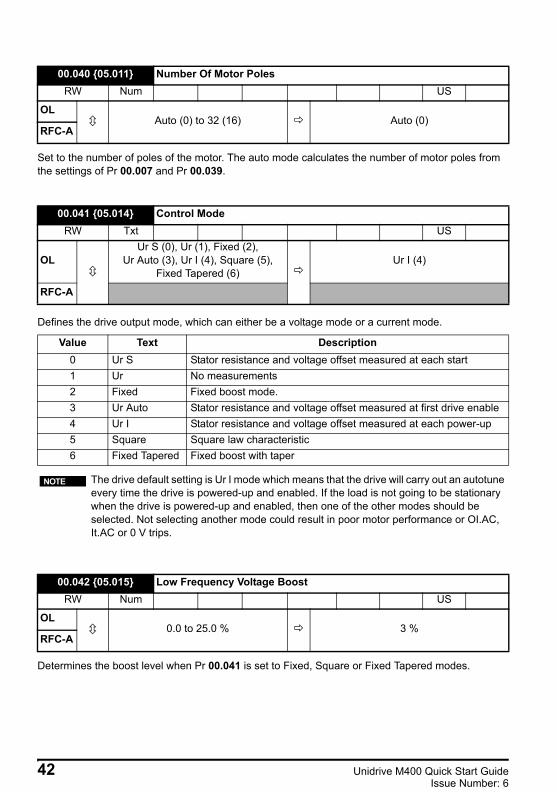
Set to the number of poles of the motor. The auto mode calculates the number of motor poles from the settings of Pr 00.007 and Pr 00.039.
Defines the drive output mode, which can either be a voltage mode or a current mode.
Determines the boost level when Pr 00.041 is set to Fixed, Square or Fixed Tapered modes.
00.040 05.011 Number Of Motor PolesRW Num US
OLAuto (0) to 32 (16) Auto (0)
RFC-A
00.041 05.014 Control ModeRW Txt US
OLUr S (0), Ur (1), Fixed (2),
Ur Auto (3), Ur I (4), Square (5), Fixed Tapered (6)
Ur I (4)
RFC-A
Value Text Description0 Ur S Stator resistance and voltage offset measured at each start1 Ur No measurements2 Fixed Fixed boost mode.3 Ur Auto Stator resistance and voltage offset measured at first drive enable4 Ur I Stator resistance and voltage offset measured at each power-up5 Square Square law characteristic6 Fixed Tapered Fixed boost with taper
The drive default setting is Ur I mode which means that the drive will carry out an autotune every time the drive is powered-up and enabled. If the load is not going to be stationary when the drive is powered-up and enabled, then one of the other modes should be selected. Not selecting another mode could result in poor motor performance or OI.AC, It.AC or 0 V trips.
00.042 05.015 Low Frequency Voltage BoostRW Num US
OL0.0 to 25.0 % 3 %
RFC-A
NOTE
42 Unidrive M400 Quick Start GuideIssue Number: 6
Unidrive M400 Quick Start Guide English Iss3.book Page 43 Tuesday, September 15, 2015 9:32 AM
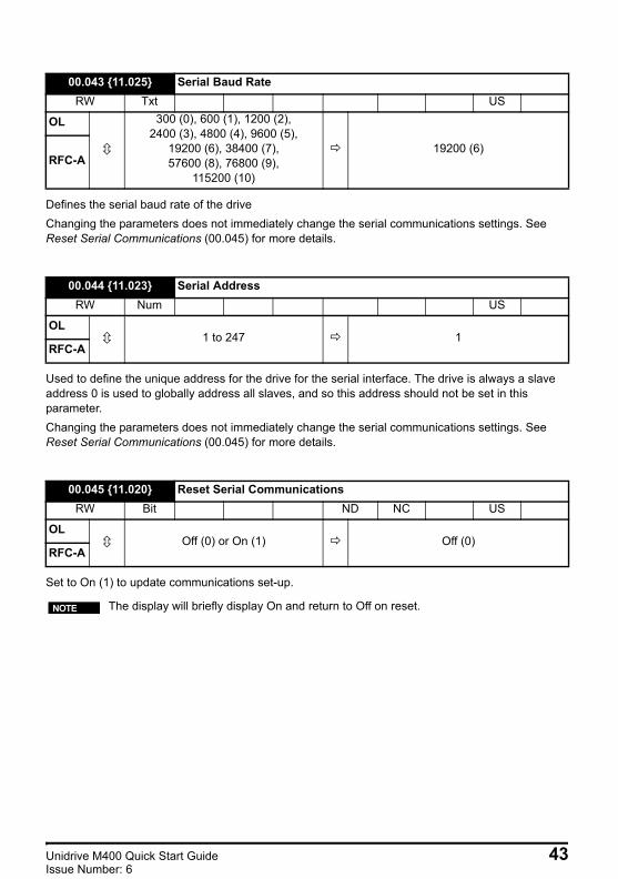
Defines the serial baud rate of the driveChanging the parameters does not immediately change the serial communications settings. See Reset Serial Communications (00.045) for more details.
Used to define the unique address for the drive for the serial interface. The drive is always a slave address 0 is used to globally address all slaves, and so this address should not be set in this parameter.Changing the parameters does not immediately change the serial communications settings. See Reset Serial Communications (00.045) for more details.
Set to On (1) to update communications set-up.
00.043 11.025 Serial Baud RateRW Txt US
OL 300 (0), 600 (1), 1200 (2),2400 (3), 4800 (4), 9600 (5),
19200 (6), 38400 (7),57600 (8), 76800 (9),
115200 (10)
19200 (6)RFC-A
00.044 11.023 Serial AddressRW Num US
OL1 to 247 1
RFC-A
00.045 11.020 Reset Serial CommunicationsRW Bit ND NC US
OLOff (0) or On (1) Off (0)
RFC-A
The display will briefly display On and return to Off on reset.NOTE
Unidrive M400 Quick Start Guide 43Issue Number: 6
Unidrive M400 Quick Start Guide English Iss3.book Page 44 Tuesday, September 15, 2015 9:32 AM
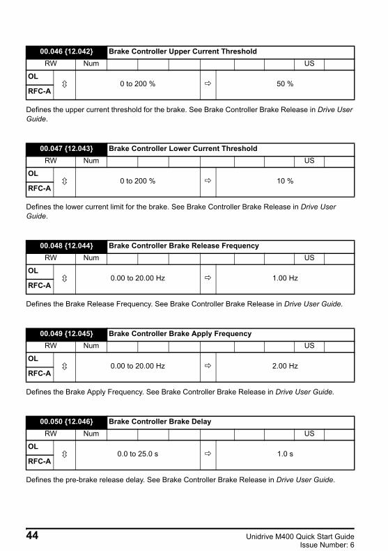
Defines the upper current threshold for the brake. See Brake Controller Brake Release in Drive User Guide.
Defines the lower current limit for the brake. See Brake Controller Brake Release in Drive User Guide.
Defines the Brake Release Frequency. See Brake Controller Brake Release in Drive User Guide.
Defines the Brake Apply Frequency. See Brake Controller Brake Release in Drive User Guide.
Defines the pre-brake release delay. See Brake Controller Brake Release in Drive User Guide.
00.046 12.042 Brake Controller Upper Current ThresholdRW Num US
OL0 to 200 % 50 %
RFC-A
00.047 12.043 Brake Controller Lower Current ThresholdRW Num US
OL0 to 200 % 10 %
RFC-A
00.048 12.044 Brake Controller Brake Release FrequencyRW Num US
OL0.00 to 20.00 Hz 1.00 Hz
RFC-A
00.049 12.045 Brake Controller Brake Apply FrequencyRW Num US
OL0.00 to 20.00 Hz 2.00 Hz
RFC-A
00.050 12.046 Brake Controller Brake DelayRW Num US
OL0.0 to 25.0 s 1.0 s
RFC-A
44 Unidrive M400 Quick Start GuideIssue Number: 6

Unidrive M400 Quick Start Guide English Iss3.book Page 45 Tuesday, September 15, 2015 9:32 AM
Defines the post-brake release delay.
Defines the initial direction of the brake.
See Brake Controller Brake Release in Drive User Guide.
Defines if the brake is applied through zero threshold. See Brake Controller Brake Release in Drive User Guide.
00.051 12.047 Brake Controller Post-brake Release DelayRW Num US
OL0.0 to 25.0 s 1.0 s
RFC-A
00.053 12.047 Brake Controller Initial DirectionRW Txt US
OLRef (0), Forward (1), Reverse (2) Ref (0)
RFC-A
Value Text0 Ref1 Forward 2 Reverse
00.054 12.051 Brake Controller Brake Apply Through Zero ThresholdRW Num US
OL0.00 to 25.00 Hz 0.00 Hz
RFC-A
00.055 12.041 Brake Controller EnableRW Txt US
OL Disable (0), Relay (1), Digital IO (2), User (3) Disable (0)
RFC-A
Value Text0 Disable 1 Relay2 Digital IO3 User
Unidrive M400 Quick Start Guide 45Issue Number: 6
Unidrive M400 Quick Start Guide English Iss3.book Page 46 Tuesday, September 15, 2015 9:32 AM
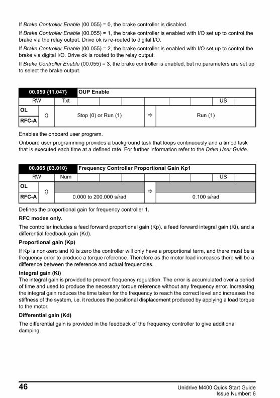
If Brake Controller Enable (00.055) = 0, the brake controller is disabled.If Brake Controller Enable (00.055) = 1, the brake controller is enabled with I/O set up to control the brake via the relay output. Drive ok is re-routed to digital I/O.If Brake Controller Enable (00.055) = 2, the brake controller is enabled with I/O set up to control the brake via digital I/O. Drive ok is routed to the relay output.If Brake Controller Enable (00.055) = 3, the brake controller is enabled, but no parameters are set up to select the brake output.
Enables the onboard user program.Onboard user programming provides a background task that loops continuously and a timed task that is executed each time at a defined rate. For further information refer to the Drive User Guide.
Defines the proportional gain for frequency controller 1.RFC modes only. The controller includes a feed forward proportional gain (Kp), a feed forward integral gain (Ki), and a differential feedback gain (Kd). Proportional gain (Kp)If Kp is non-zero and Ki is zero the controller will only have a proportional term, and there must be a frequency error to produce a torque reference. Therefore as the motor load increases there will be a difference between the reference and actual frequencies. Integral gain (Ki)The integral gain is provided to prevent frequency regulation. The error is accumulated over a period of time and used to produce the necessary torque reference without any frequency error. Increasing the integral gain reduces the time taken for the frequency to reach the correct level and increases the stiffness of the system, i.e. it reduces the positional displacement produced by applying a load torque to the motor. Differential gain (Kd)The differential gain is provided in the feedback of the frequency controller to give additional damping.
00.059 11.047 OUP EnableRW Txt US
OLStop (0) or Run (1) Run (1)
RFC-A
00.065 03.010 Frequency Controller Proportional Gain Kp1RW Num US
OL
RFC-A 0.000 to 200.000 s/rad 0.100 s/rad
46 Unidrive M400 Quick Start GuideIssue Number: 6
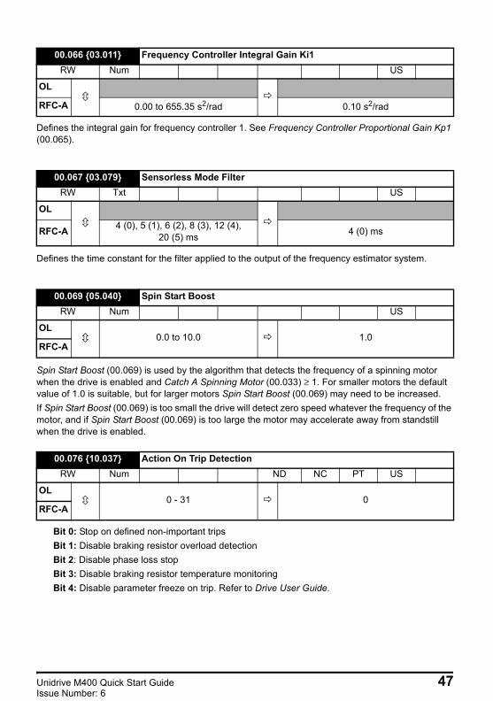
Unidrive M400 Quick Start Guide English Iss3.book Page 47 Tuesday, September 15, 2015 9:32 AM
Defines the integral gain for frequency controller 1. See Frequency Controller Proportional Gain Kp1 (00.065).
Defines the time constant for the filter applied to the output of the frequency estimator system.
Spin Start Boost (00.069) is used by the algorithm that detects the frequency of a spinning motor when the drive is enabled and Catch A Spinning Motor (00.033) ≥ 1. For smaller motors the default value of 1.0 is suitable, but for larger motors Spin Start Boost (00.069) may need to be increased. If Spin Start Boost (00.069) is too small the drive will detect zero speed whatever the frequency of the motor, and if Spin Start Boost (00.069) is too large the motor may accelerate away from standstill when the drive is enabled.
Bit 0: Stop on defined non-important tripsBit 1: Disable braking resistor overload detectionBit 2: Disable phase loss stopBit 3: Disable braking resistor temperature monitoringBit 4: Disable parameter freeze on trip. Refer to Drive User Guide.
00.066 03.011 Frequency Controller Integral Gain Ki1RW Num US
OL
RFC-A 0.00 to 655.35 s2/rad 0.10 s2/rad
00.067 03.079 Sensorless Mode FilterRW Txt US
OL
RFC-A 4 (0), 5 (1), 6 (2), 8 (3), 12 (4), 20 (5) ms 4 (0) ms
00.069 05.040 Spin Start BoostRW Num US
OL0.0 to 10.0 1.0
RFC-A
00.076 10.037 Action On Trip DetectionRW Num ND NC PT US
OL0 - 31 0
RFC-A
Unidrive M400 Quick Start Guide 47Issue Number: 6
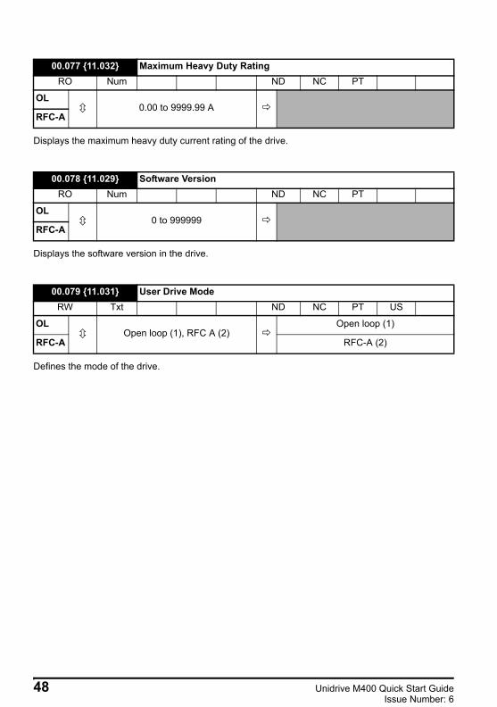
Unidrive M400 Quick Start Guide English Iss3.book Page 48 Tuesday, September 15, 2015 9:32 AM
Displays the maximum heavy duty current rating of the drive.
Displays the software version in the drive.
Defines the mode of the drive.
00.077 11.032 Maximum Heavy Duty RatingRO Num ND NC PT
OL0.00 to 9999.99 A
RFC-A
00.078 11.029 Software VersionRO Num ND NC PT
OL0 to 999999
RFC-A
00.079 11.031 User Drive ModeRW Txt ND NC PT US
OLOpen loop (1), RFC A (2)
Open loop (1)
RFC-A RFC-A (2)
48 Unidrive M400 Quick Start GuideIssue Number: 6
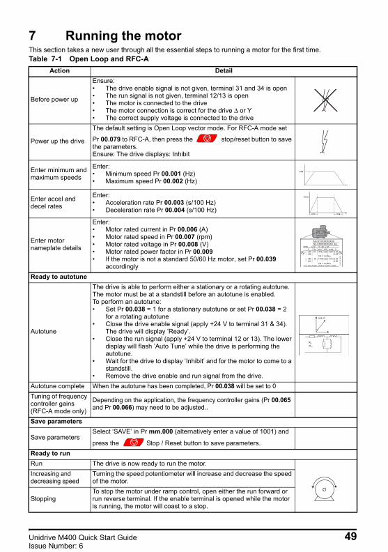
Unidrive M400 Quick Start Guide English Iss3.book Page 49 Tuesday, September 15, 2015 9:32 AM
7 Running the motor This section takes a new user through all the essential steps to running a motor for the first time. Table 7-1 Open Loop and RFC-A
Action Detail
Before power up
Ensure:• The drive enable signal is not given, terminal 31 and 34 is open• The run signal is not given, terminal 12/13 is open• The motor is connected to the drive• The motor connection is correct for the drive Δ or Y• The correct supply voltage is connected to the drive
Power up the drive
The default setting is Open Loop vector mode. For RFC-A mode set
Pr 00.079 to RFC-A, then press the stop/reset button to save the parameters.Ensure: The drive displays: Inhibit
Enter minimum and maximum speeds
Enter:• Minimum speed Pr 00.001 (Hz)• Maximum speed Pr 00.002 (Hz)
Enter accel and decel rates
Enter:• Acceleration rate Pr 00.003 (s/100 Hz)• Deceleration rate Pr 00.004 (s/100 Hz)
Enter motor nameplate details
Enter:• Motor rated current in Pr 00.006 (A)• Motor rated speed in Pr 00.007 (rpm)• Motor rated voltage in Pr 00.008 (V)• Motor rated power factor in Pr 00.009• If the motor is not a standard 50/60 Hz motor, set Pr 00.039
accordinglyReady to autotune
Autotune
The drive is able to perform either a stationary or a rotating autotune. The motor must be at a standstill before an autotune is enabled. To perform an autotune:• Set Pr 00.038 = 1 for a stationary autotune or set Pr 00.038 = 2
for a rotating autotune• Close the drive enable signal (apply +24 V to terminal 31 & 34).
The drive will display ’Ready’.• Close the run signal (apply +24 V to terminal 12 or 13). The lower
display will flash ’Auto Tune’ while the drive is performing the autotune.
• Wait for the drive to display ‘Inhibit’ and for the motor to come to a standstill.
• Remove the drive enable and run signal from the drive.Autotune complete When the autotune has been completed, Pr 00.038 will be set to 0 Tuning of frequency controller gains (RFC-A mode only)
Depending on the application, the frequency controller gains (Pr 00.065and Pr 00.066) may need to be adjusted..
Save parameters
Save parametersSelect ‘SAVE’ in Pr mm.000 (alternatively enter a value of 1001) and
press the Stop / Reset button to save parameters.Ready to runRun The drive is now ready to run the motor.Increasing and decreasing speed
Turning the speed potentiometer will increase and decrease the speed of the motor.
StoppingTo stop the motor under ramp control, open either the run forward or run reverse terminal. If the enable terminal is opened while the motor is running, the motor will coast to a stop.
0.02
t
100Hz
0.03t
0.04
Mot X XXXXXXXXXNo XXXXXXXXXX kg
IP55 I.cl F C 40 s S1°V Hz min-1 kW cosφ A230400
50 1445 2.20 0.80 8.504.90
CN = 14.5Nm240415
50 1445 2.20 0.76 8.504.90
CN = 14.4NmCTP- VEN 1PHASE 1=0,46A P=110W R.F 32MN I.E
.C 3
4 1(
87)
cos ∅
σLS
RS
Unidrive M400 Quick Start Guide 49Issue Number: 6

Unidrive M400 Quick Start Guide English Iss3.book Page 50 Tuesday, September 15, 2015 9:32 AM
8 Diagnostics
Table 8-1 Trip indications
Users must not attempt to repair a drive if it is faulty, nor carry out fault diagnosis other than through the use of the diagnostic features described in this chapter.If a drive is faulty, it must be returned to the supplier of the drive for repair.
Trip code Condition Description
An Input 1 Loss Analog input 1 current loss Current loss was detected in current mode on Analog input 1 (Terminal 2).
An Input 1 OI Analog input 1 over-current Current input on analog input 1 exceeds 24 mA.
An Input 2 Loss Analog input 2 current loss Current loss was detected in current mode on Analog input 2 (Terminal 5).
An Input 2 OI Analog input 2 over-current Current input on analog input 2 exceeds 24 mA.
Autotune Measured inertia has exceeded the parameter range
The drive has tripped during a rotating autotune or mechanical load measurement test.
Autotune Stopped Autotune test stopped before completion
The drive was prevented from completing an autotune test, because either the drive enable or the drive run signals were removed.
Brake R Too HotBraking resistor overload timed out (I2t)
Braking resistor overload has timed out.
Card Access NV Media Card Write fail Unable to access the NV Media Card.
Card BootThe Menu 0 parameter modification cannot be saved to the NV Media Card
The necessary boot file has not been created on the NV media card fitted to the drive to take the new parameter value. This occurs when Parameter Cloning (00.030) is changed to auto or boot mode, but the drive is not subsequently reset.
Card BusyNV Media Card cannot be accessed as it is being accessed by an option module
The Card Busy trip indicates that an attempt has been made to access a file on NV Media Card, but the NV Media Card is already being accessed by an option module. No data is transferred.
Card Compare NV Media Card file/data is different to the one in the drive
Trip is initiated if the parameters on the NV Media Card are different to the drive.
Card Data Exists NV Media Card data location already contains data
Attempt has been made to store data on a NV Media Card in a data block which already contains data.
Card Drive ModeNV Media Card parameter set not compatible with current drive mode
The drive mode in the data block on the NV Media Card is different from the current drive mode.
Card Error NV Media Card data structure error
Attempt has been made to access the NV Media Card but an error has been detected in the data structure on the card. Resetting the trip will cause the drive to erase and create the correct folder structure.
Card Full NV Media Card full There is not enough space left on the card.
Card No Data NV Media Card data not found Attempt has been made to access non-existent file or block on the NV Media Card.
Card OptionNV Media Card trip; option modules installed are different between source drive and destination drive
The Card Option trip indicates that parameter data or default difference data is being transferred from the NV Media Card to the drive, but the option module category is different between the source and destination drives.
Card ProductNV Media Card data blocks are not compatible with the drive derivative
If Drive Derivative is different between the source and target drives. Refer to the Drive User Guide.
WARNING
50 Unidrive M400 Quick Start GuideIssue Number: 6
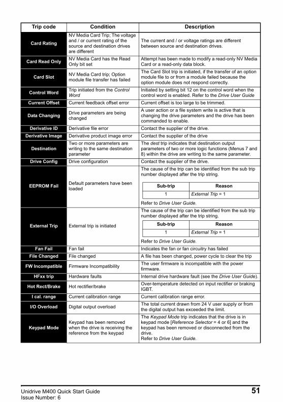
Unidrive M400 Quick Start Guide English Iss3.book Page 51 Tuesday, September 15, 2015 9:32 AM
Card RatingNV Media Card Trip; The voltage and / or current rating of the source and destination drives are different
The current and / or voltage ratings are different between source and destination drives.
Card Read Only NV Media Card has the Read Only bit set
Attempt has been made to modify a read-only NV Media Card or a read-only data block.
Card Slot NV Media Card trip; Option module file transfer has failed
The Card Slot trip is initiated, if the transfer of an option module file to or from a module failed because the option module does not respond correctly.
Control Word Trip initiated from the Control Word
Initiated by setting bit 12 on the control word when the control word is enabled. Refer to the Drive User Guide
Current Offset Current feedback offset error Current offset is too large to be trimmed.
Data Changing Drive parameters are being changed
A user action or a file system write is active that is changing the drive parameters and the drive has been commanded to enable.
Derivative ID Derivative file error Contact the supplier of the drive.Derivative Image Derivative product image error Contact the supplier of the drive
DestinationTwo or more parameters are writing to the same destination parameter
The dest trip indicates that destination output parameters of two or more logic functions (Menus 7 and 8) within the drive are writing to the same parameter.
Drive Config Drive configuration Contact the supplier of the drive.
EEPROM Fail Default parameters have been loaded
The cause of the trip can be identified from the sub trip number displayed after the trip string.
Refer to Drive User Guide.
External Trip External trip is initiated
The cause of the trip can be identified from the sub trip number displayed after the trip string.
Refer to Drive User Guide.Fan Fail Fan fail Indicates the fan or fan circuitry has failed
File Changed File changed A file has been changed, power cycle to clear the trip
FW Incompatible Firmware Incompatibility The user firmware is incompatible with the power firmware.
HFxx trip Hardware faults Internal drive hardware fault (see the Drive User Guide).
Hot Rect/Brake Hot rectifier/brake Over-temperature detected on input rectifier or braking IGBT.
I cal. range Current calibration range Current calibration range error.
I/O Overload Digital output overload The total current drawn from 24 V user supply or from the digital output has exceeded the limit.
Keypad ModeKeypad has been removed when the drive is receiving the reference from the keypad
The Keypad Mode trip indicates that the drive is in keypad mode [Reference Selector = 4 or 6] and the keypad has been removed or disconnected from the drive.Refer to Drive User Guide.
Trip code Condition Description
Sub-trip Reason1 External Trip = 1
Sub-trip Reason1 External Trip = 1
Unidrive M400 Quick Start Guide 51Issue Number: 6

Unidrive M400 Quick Start Guide English Iss3.book Page 52 Tuesday, September 15, 2015 9:32 AM
Motor Too HotOutput current overload timed out (I2t)
trip indicates a motor thermal overload based on the output current and motor thermal time constant. The drive will trip on It.Ac when the accumulator gets to 100 %.This can occur when:• There is excessive mechanical load• Ensure the load is not jammed / sticking• Check the load on the motor has not changed• Ensure the motor rated current is not zero
No power board No power board No communication between the power and control boards.
OHt Brake Braking IGBT over-temperature Braking IGBT over-temperature OHt Control Control stage over-temperature Control stage over-temperature
OHt dc bus DC bus over temperature DC bus component over temperature based on a software thermal model.
OHt Inverter Inverter over temperature based on thermal model
IGBT junction over-temperature has been detected based on a software thermal model.
OHt Power Power stage over temperature This trip indicates that a power stage over-temperature has been detected.
OHt Rectifier Rectifier over temperature The OHt Rectifier trip indicates that a rectifier over-temperature has been detected.
OI ac Instantaneous output over current detected
The instantaneous drive output current has exceeded.The set limit.
Possible solutions:• Increase acceleration/deceleration rate• If seen during autotune reduce the voltage boost• Check for short circuit on the output cabling• Check integrity of the motor insulation using an
insulation tester• Is the motor cable length within limits for the frame
size• Reduce the values in the current loop gain
parameters
OI BrakeBraking IGBT over current detected: short circuit protection for the braking IGBT activated
Over current has been detected in braking IGBT or braking IGBT protection has been activated.Possible cause:• Check brake resistor wiring• Check braking resistor value is greater than or
equal to the minimum resistance value• Check braking resistor insulation
Option DisableOption module does not acknowledge during drive mode changeover
Option module did not acknowledge notifying the drive that communications with the drive has been stopped during the drive mode changeover within the allocated time.
Out Phase Loss Output phase loss detected Phase loss has been detected at the drive output.Output phase s/c Output phase short-circuit Over-current detected on drive output when enabled.
Over Speed Motor frequency has exceeded the over frequency threshold
Excessive motor speed (typically caused by mechanical load driving the motor).
Trip code Condition Description
52 Unidrive M400 Quick Start GuideIssue Number: 6

Unidrive M400 Quick Start Guide English Iss3.book Page 53 Tuesday, September 15, 2015 9:32 AM
Over VoltsDC bus voltage has exceeded the peak level or maximum continuous level for 15 seconds
The OV trip indicates that the DC bus voltage has exceeded the maximum limit.Possible solutions:• Increase Deceleration Rate 1 (Pr 00.004)• Decrease the braking resistor value (staying above
the minimum value).• Check nominal AC supply level.• Check for supply disturbances which could cause
the DC bus to rise.• Check motor insulation using a insulation tester.
Phase Loss Supply phase loss The drive has detected an input phase loss or large supply imbalance.
Power Board HF Power board HF Power processor hardware fault.
Power CommsCommunication has been lost / errors detected between power control
No communications between power control.
Power Data Power system configuration data error
Error in the configuration data stored in the power system.
Power Down Save Power down save error Error has been detected in the power down save parameters saved in non-volatile memory.
PSU Internal power supply fault One or more internal power supply rails are outside limits or overloaded.
Resistance Measured resistance has exceeded the parameter range
The measured stator resistance during an autotune test has exceeded the maximum possible value of Stator Resistance.Refer to the Drive User Guide.
Slot 1 Different Option module in option slot 1 has changed
Option module in option slot 1 on the drive is a different type to that installed when parameters were last saved on the drive.
Slot 1 Error Option module in option slot 1 has detected a fault
Option module in option slot 1 on the drive has detected an error.
Slot 1 HF Option module 1 hardware fault Option module in option slot 1 on the drive has indicated a hardware fault.
Slot 1 Not Fitted Option module in option slot 1 has been removed
Option module in option slot 1 on the drive has been removed since the last power up.
Slot 1 Watchdog Option module watchdog function service error
Option module installed in Slot 1 has started the option watchdog function and then failed to service the watchdog correctly.
Soft Start Soft start relay failed to close, soft start monitor failed
Soft start relay in the drive failed to close or the soft start monitoring circuit has failed.
STO Error No Safe Torque Off board installed STO board not installed.
Stored HF Hardware trip has occurred during last power down
Hardware trip (HF01 –HF19) has occurred and the drive has been power cycled. Enter 1299 to xx.000 to clear trip
Sub-array RAM RAM allocation errorThe Sub-array RAM trip indicates that an option module derivative image has requested more parameter RAM than is allowed.
Temp Feedback Internal thermistor has failed Internal thermistor has failed.
Th Brake Res Brake resistor over temperatureThe th.br trip is initiated if the hardware based braking resistor thermal monitoring is connected and the resistor overheats.
Th Short Circuit Motor thermistor short circuit
The Th Short Circuit trip indicates that the motor thermistor connected to terminal 14 (digital input 5) on the control connections, is short circuit or low impedance (<50 Ω).
Trip code Condition Description
Unidrive M400 Quick Start Guide 53Issue Number: 6

Unidrive M400 Quick Start Guide English Iss3.book Page 54 Tuesday, September 15, 2015 9:32 AM
Thermistor Motor thermistor over-temperature
The Thermistor trip indicates that the motor thermistor connected to terminal 14 (digital input 5) on the control connections has indicated a motor over temperature.
User 24 VUser 24 V supply is not present on the adaptor interface terminals (1,2)
A US.24 trip is initiated if the User Supply Select is set to 1 and no user 24 V supply is present on the user 24 V input on the AI-Backup adaptor. Refer to the Drive User Guide.
User OI ac User OI acThe U.OI trip is initiated if the output current of the drive exceeds the trip level set by User Over Current Trip Level. Refer to the Drive User Guide.
User Prog Trip Trip generated by an onboard user program
This trip can be initiated from within an onboard user program
User Program On board user program error An error has been detected in the onboard user program image.
User Save User Save error / not completed The U.S trip indicates that an error has been detected in the user save parameters saved in non-volatile memory.
Watchdog Control word watchdog has timed out
The Watchdog trip indicates that the control word has been enabled and has timed out
Trip code Condition Description
54 Unidrive M400 Quick Start GuideIssue Number: 6

Unidrive M400 Quick Start Guide English Iss3.book Page 55 Tuesday, September 15, 2015 9:32 AM
9 NV Media Card OperationFigure 9-1 Installing the AI-Backup adaptor (SD Card)
1. Identify the two plastic fingers on the underside of the AI-Backup adaptor (1) - then insert the two fingers into the corresponding slots in the spring-loaded sliding cover on the top of the drive.
2. Hold the adaptor firmly and push the spring loaded protective cover towards the back of the drive to expose the connector block (2) below.
Press the adaptor downwards (3) until the adaptor connector locates into the drive connection below.Figure 9-2 Basic NV Media Card operation
The whole card may be protected from writing or erasing by setting the read-only flag, refer to the Drive User Guide for further information. The card should not be removed during data transfer, as the drive will produce a trip. If this occurs then either the transfer should be reattempted or in the case of a card to drive transfer, default parameters should be loaded.
1
2
111
3
Pr = rEAd +00.030
Drive reads allparameters fromthe NV Media Card
Pr = Prog +00.030
Programs all driveparameters to theNV Media Card
NOTE
Overwrites anydata already indata block 1
Pr = Auto +00.030
Drive automaticallywrites to the
when a parametersave is performed
Media Card
Pr = boot +00.030
Drive boots from theNV Media Card onpower up andautomatically writesto thewhen a parametersave is performed
Media Card
1
2
1
2
1
2
1
2
1
2
Unidrive M400 Quick Start Guide 55Issue Number: 6

Unidrive M400 Quick Start Guide English Iss3.book Page 56 Tuesday, September 15, 2015 9:32 AM
10 Machine Control StudioMachine Control Studio programming software powered by CODESYSMachine Control Studio software provides a flexible and intuitive environment for programming Unidrive M's new automation and motion control features. This new software offers programming for the Unidrive M400's onboard PLC.Machine Control Studio is powered by CODESYS, the leading open software for programmable machine control. The programming environment is fully EN/IEC 61131-3 compliant, meaning that it is familiar and therefore fast and easy to use for control engineers around the world.The following EN/IEC 61131-3 programming languages are supported:• Structured Text (ST)• Function Block Diagram (FBD)• Structured Function Chart (SFC)• Ladder Diagram (LD)• Instruction List (IL)Also supported:• Continuous Function Chart (CFC)
Onboard intelligence• Programmable Logic Control (PLC) - memory: 12 kB• 1 x Real-time task (16 ms), 1 x Background taskIntuitive IntelliSense functionality helps to write consistent and robust programming, speeding up software development. Programmers have access to a vibrant open-source community for function blocks. Machine Control Studio supports customers' own function block libraries, with on-line monitoring of program variables with user defined watch windows and help for on-line change of program, in line with current PLC practices.
Download Machine Control Studio from: http://www.emersonindustrial.com/en-EN/controltechniques/downloads/userguidesandsoftware/Pages/unidrivem.aspx under the 'Software' section or http://www.emersonindustrial.com/fr-FR/leroy-somer-motors-drives/downloads/Pages/softwares-and-drawings.aspx
56 Unidrive M400 Quick Start GuideIssue Number: 6
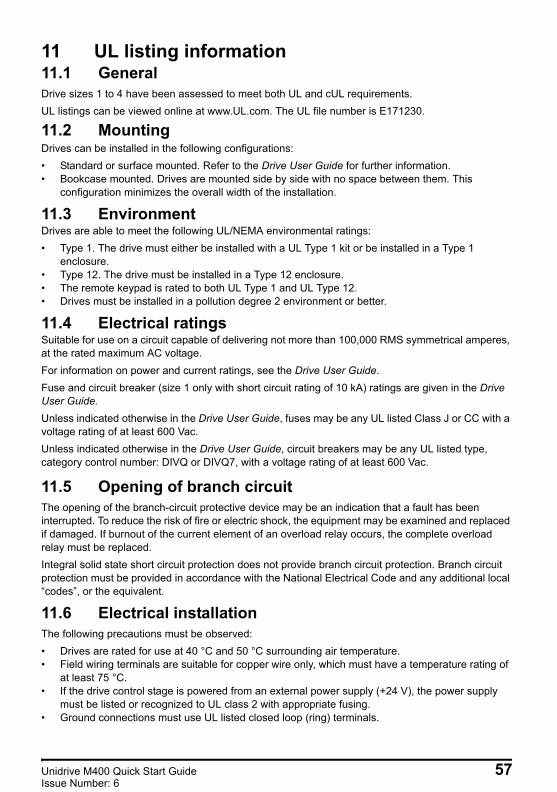
Unidrive M400 Quick Start Guide English Iss3.book Page 57 Tuesday, September 15, 2015 9:32 AM
11 UL listing information11.1 GeneralDrive sizes 1 to 4 have been assessed to meet both UL and cUL requirements.UL listings can be viewed online at www.UL.com. The UL file number is E171230.
11.2 MountingDrives can be installed in the following configurations:• Standard or surface mounted. Refer to the Drive User Guide for further information.• Bookcase mounted. Drives are mounted side by side with no space between them. This
configuration minimizes the overall width of the installation.
11.3 EnvironmentDrives are able to meet the following UL/NEMA environmental ratings:• Type 1. The drive must either be installed with a UL Type 1 kit or be installed in a Type 1
enclosure.• Type 12. The drive must be installed in a Type 12 enclosure.• The remote keypad is rated to both UL Type 1 and UL Type 12.• Drives must be installed in a pollution degree 2 environment or better.
11.4 Electrical ratingsSuitable for use on a circuit capable of delivering not more than 100,000 RMS symmetrical amperes, at the rated maximum AC voltage.For information on power and current ratings, see the Drive User Guide.Fuse and circuit breaker (size 1 only with short circuit rating of 10 kA) ratings are given in the Drive User Guide.Unless indicated otherwise in the Drive User Guide, fuses may be any UL listed Class J or CC with a voltage rating of at least 600 Vac.Unless indicated otherwise in the Drive User Guide, circuit breakers may be any UL listed type, category control number: DIVQ or DIVQ7, with a voltage rating of at least 600 Vac.
11.5 Opening of branch circuitThe opening of the branch-circuit protective device may be an indication that a fault has been interrupted. To reduce the risk of fire or electric shock, the equipment may be examined and replaced if damaged. If burnout of the current element of an overload relay occurs, the complete overload relay must be replaced. Integral solid state short circuit protection does not provide branch circuit protection. Branch circuit protection must be provided in accordance with the National Electrical Code and any additional local “codes”, or the equivalent.
11.6 Electrical installationThe following precautions must be observed:• Drives are rated for use at 40 °C and 50 °C surrounding air temperature.• Field wiring terminals are suitable for copper wire only, which must have a temperature rating of
at least 75 °C.• If the drive control stage is powered from an external power supply (+24 V), the power supply
must be listed or recognized to UL class 2 with appropriate fusing.• Ground connections must use UL listed closed loop (ring) terminals.
Unidrive M400 Quick Start Guide 57Issue Number: 6

Unidrive M400 Quick Start Guide English Iss3.book Page 58 Tuesday, September 15, 2015 9:32 AM
11.7 Motor overload protectionAll models incorporate internal overload protection for the motor load that does not require the use of an external or remote overload protection device. The protection level is adjustable and the method of adjustment is provided within instructions/manual for the product. Maximum current overload is dependent on the values entered into the current limit parameters (Motoring Current Limit (04.005), Regenerative Current Limit (04.006) and Symmetrical Current Limit (04.007) entered as percentage) and the Motor Rated Current (00.006) entered in amperes). The duration of the overload is dependent on Motor Thermal Time Constant (04.015) variable up to a maximum of 3000 seconds. The default overload protection is set such that the product is capable of 150 % of the current value entered into the motor rated current parameter for 60 seconds. The product can be connected to a motor thermistor to protect the motor, in the event of a motor cooling fan failure.
11.8 Motor overspeed protectionThe drive is installed with solid state motor overspeed protection.However, this feature does not provide the level of protection provided by an independent, high-integrity overspeed protection device and should not be considered as a safety function.
11.9 Thermal memory retentionDrives incorporate thermal memory retention that complies fully with the requirements of UL508C.The drive is provided with motor load and speed sensitive overload protection with thermal memory retention that complies with the US National Electrical Code (NFPA 70) clause 430.126 and Underwriters Laboratories Standard UL508C, clause 20.1.11 (a). The purpose of this protection is to protect both drive and motor from dangerous overheating in the event of repeated overload or failure to start, even if the power to the drive is removed between overload events.For full explanation of the thermal protection system, refer to the Drive User Guide for further information.In order to comply with UL requirements for thermal memory retention, it is necessary to set the Thermal Protection Mode (04.016) to zero; and the Low Frequency Thermal Protection Mode (04.025) must be set to 1 if the drive is operated in Heavy Duty mode.Alternatively, an external thermal sensor or switch may be used as a means of motor and drive overload protection that complies with the requirements of UL508C, clause 20.1.11 (b). This protection method is particularly recommended where independent forced cooling of the motor is used, because of the risk of overheating if the cooling is lost.External thermal sensorThe drive is provided with a means to accept and act upon a signal from a thermal sensor or switch imbedded in the motor or from an external protective relay. Refer to the Drive User Guide for further information.
58 Unidrive M400 Quick Start GuideIssue Number: 6
Unidrive M400 Quick Start Guide English Iss3.book Page 59 Tuesday, September 15, 2015 9:32 AM
11.10 Group installation11.10.1 DefinitionGroup Installation Definition: A motor branch circuit for two or more motors, or one or more motors with other loads, protected by a circuit breaker or a single set of fuses.
11.10.2 Limitations on useAll motors rated less than 1 hpThe drives may be used in group installations where each of the motors is rated 1 hp or less. The full-load current rating of each motor must not exceed 6 A. The motor drive provides individual overload protection in accordance with the NEC clause 430.32. Smallest motor protectedThe drives may be used in group installations where the smallest motor is protected by the branch fuses or circuit breaker. Limits on the current rating of branch circuit protective fuses and circuit breakers are given in the NEC Table: 430.52.Other installationsThe motor drives described in this user guide are not UL listed for group installation.
11.11 UL listed accessoriesThe following options are UL listed:• CI-Keypad• CI-485 Adaptor• AI-485 Adaptor• AI-Backup Adaptor• Remote Keypad• UL Type 1 kit• NV Media card• SI-PROFIBUS• SI-DeviceNet• SI-CANopen• SI-Ethernet• SI-EtherCAT• SI-I/O
Unidrive M400 Quick Start Guide 59Issue Number: 6
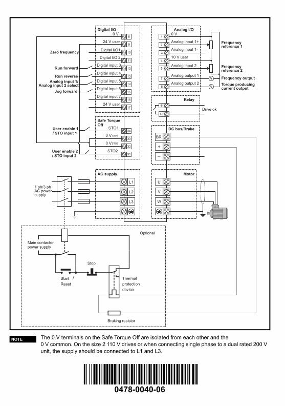
0478-0040-06
The 0 V terminals on the Safe Torque Off are isolated from each other and the 0 V common. On the size 2 110 V drives or when connecting single phase to a dual rated 200 V unit, the supply should be connected to L1 and L3.
9
10
11
12
24 V user
Digital I/O1
Digital I/O 2
Digital input 3
13Digital input 4
14Digital input 5
Digital I/O
L1
L2
L3
1 ph/3 phAC powersupply
1
2
3
0 VAnalog I/O
Analog input 1+
Analog input 1-
U
BR
+
_
V
W
41
42
Drive ok
Relay
AC supply
DC bus/Brake
Motor
60 V
15Digital input 6
16Digital input 7
7
8
Analog output 1
Analog output 2
Zero frequency
Run forward
Run reverse
Jog forward
Analog input 1/Analog input 2 select
1724 V user
32
User enable 2/ STO input 2
0 VSTO2
31STO2
34STO1
330 V ST01
User enable 1/ STO input 1
Safe TorqueOff
410 V user
5Analog input 2
Frequencyreference 1
Frequencyreference 2
Frequency output
Torque producingcurrent output
Stop
Start /Reset
Thermal
protection
device
Braking resistor
Main contactorpower supply
Optional
NOTE
Unidrive M400 Quick Start Guide English Iss3.book Page 60 Tuesday, September 15, 2015 9:32 AM