uniform technical prescriptions (utp) applicable to ... · 1 tsi noise in force (2006) – the...
TRANSCRIPT

OTIF GENERAL PROVISIONS
ROLLING STOCK – NOISE UTP NOI Page 1 of 48
Status: DRAFT Version: 01 Ref.: A 94-04/1.2011 Original: EN Date: 31.01.2011
G:\Technik\Fachausschuss technische Fragen\Working groups\TECH\WG_TECH_03_11\Documents\NEW\A_94-04_1_2011_e (UTP NOI - Noise)_e.doc
APTU Uniform Rules (Appendix F to COTIF 1999)
Uniform Technical Prescriptions (UTP) applicable to Rolling Stock, General provisions
NOISE - (UTP NOI)
These regulations have been developed in accordance with the provisions of APTU, in particular Article 8, in the version as amended by the OTIF Revision Committee in 2009, which entered into force on 1 Decem-ber 2010.
For definitions and terms, see Article 2 of ATMF (Appendix G) and Article 2 of APTU (Appendix F), both Appendices to the 1999 version of the COTIF Convention as applicable since 1 December 2010.
Note: This document is based on document A 94-01G/1.2010 and amended according to the decisions of the 12
th WG TECH (September 2010).
The basis for this draft UTP NOI is the ERA Final version of the revised TSI NOI dated 11.03.2010, as that version corrects the problems (time consuming and expensive assessments and testings) detected by the use of the first version TSI NOI.
This working document dated 31.01.2011 is the compiled 2 column draft UTP Noise, based on draft TSI NOI (version 3.1). It is intended to be presented to the 4
th Committee of Technical Experts for adoption.
OTIF GENERAL PROVISIONS
ROLLING STOCK – NOISE UTP NOI Page 2 of 48
Status: DRAFT Version: 01 Ref.: A 94-04/1.2011 Original: EN Date: 31.01.2011
G:\Technik\Fachausschuss technische Fragen\Working groups\TECH\WG_TECH_03_11\Documents\NEW\A_94-04_1_2011_e (UTP NOI - Noise)_e.doc
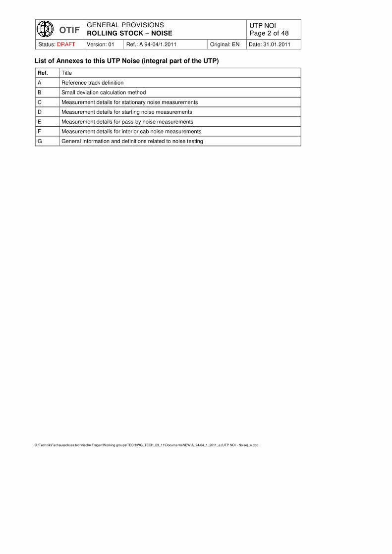
List of Annexes to this UTP Noise (integral part of the UTP)
Ref. Title
A Reference track definition
B Small deviation calculation method
C Measurement details for stationary noise measurements
D Measurement details for starting noise measurements
E Measurement details for pass-by noise measurements
F Measurement details for interior cab noise measurements
G General information and definitions related to noise testing

OTIF GENERAL PROVISIONS
ROLLING STOCK – NOISE UTP NOI Page 3 of 48
Status: DRAFT Version: 01 Ref.: A 94-04/1.2011 Original: EN Date: 31.01.2011
G:\Technik\Fachausschuss technische Fragen\Working groups\TECH\WG_TECH_03_11\Documents\NEW\A_94-04_1_2011_e (UTP NOI - Noise)_e.doc
Explanatory note:
The texts of this UTP which appear across two columns are identical to corresponding texts of the Euro-pean Union regulations. Texts which appear in two columns differ; the left-hand column contains the UTP regulations, the right-hand column shows the text in the corresponding EU regulations. The text in the right-hand column is for information only and is not part of the OTIF regulations.
OTIF UTP Corresponding text in EU regulations 1 EU ref.
2
0. EQUIVALENCE
Following their adoption by the Committee of Technical Experts, the OTIF regulations included in this document are declared equivalent to the corresponding EU regula-tions within the meaning of Article 13 of APTU and Article 3a of ATMF.
1. INTRODUCTION
1.1 TECHNICAL SCOPE
This UTP is a technical specification covering the emission of noise from the rolling stock subsystem as defined in UTP 1-B Subsystems section 2.6. Vehicles complying with the provisions of this UTP meet the essential requirements and ensure the interoperability of the conven-tional rolling stock used or intended to be used in international traffic.
This TSI concerns the conventional rail rolling stock subsystem as defined in Directive 2008/57/EC, Annex II. Further information on the rolling stock sub-system is provided in Chapter 2.
Further information on the rolling stock subsystem is provided in Section 2 of this document.
This UTP This TSI
covers noise emitted by rolling stock in the scope of this
UTP. TSI.
It sets out noise limits generated by rail-way vehicles when stationary, starting noise, pass-by noise and noise inside the driver's cab.
Noise generated from braking is not in the scope of this UTP.
[Noise from braking is not in the scope of the TSI, but not stated explicitly]
This UTP applies to new, upgraded or renewed railway vehicles for which tech-nical admission is granted after this UTP has entered into force. However, it does not apply to vehicles which are subject to a contract of purchase, upgrade or re-newal already signed before the date of entry into force of this UTP.
[see 2.1]
1 TSI Noise in force (2006) – The Annex to EU Commission Decision 2006/66/EC published in the EU Official Journal L37 on
08.02.2006 as proposed amended through ERA Final draft 3.0, published on ERA website 15.04.2010. 2 If no EU reference is indicated, it means that the chapter/section number is the same as in the OTIF text.
4 TSI: Article 20 of Directive 2008/57/EC
Formatted: Not Highlight
Deleted: OTIF conventional rail system
3.
Deleted: freight wagons
Deleted: wagons

OTIF GENERAL PROVISIONS
ROLLING STOCK – NOISE UTP NOI Page 4 of 48
Status: DRAFT Version: 01 Ref.: A 94-04/1.2011 Original: EN Date: 31.01.2011
G:\Technik\Fachausschuss technische Fragen\Working groups\TECH\WG_TECH_03_11\Documents\NEW\A_94-04_1_2011_e (UTP NOI - Noise)_e.doc
OTIF UTP Corresponding text in EU regulations 1 EU ref.
2
1.2 GEOGRAPHICAL SCOPE 2.1
1.2.1 The geographical scope of this
UTP is the OTIF conventional rail system formed of those lines in the Contracting State which carry international traffic.
TSI is the trans-European conventional rail system network (TEN) as described in Annex I to Directive 2008/57/EC.
-
1.3 CONTENT OF THIS DOCUMENT
1.3.1 This UTP In accordance with Article 5(3) of the Directive 2008/57/EC, this TSI
(a) indicates its intended scope
(part of the network or rolling stock referred to in Annex I to the Direc-tive; subsystem or part of subsys-tem referred to in Annex II to the Di-rective)
– Section 1 and 2;
(b) lays down essential requirements for the concerned rolling stock domain and for its interfaces vis-à-vis other subsystems – Section 3;
(c) establishes the functional and technical specifications to be met by the subsys-tem and its interfaces vis-à-vis other subsystems
– Section 4;
(d) states, in each case under consideration, which procedures are to be used in
order
to assess the subsystem’s conformity with this UTP
for the "EC" verification of the sub-systems
– Section 6;
(e) indicates the strategy for implementing this
UTP TSI
– Section 7;
(f) indicates, for the staff concerned, the professional qualifications and health and
safety conditions at work required for the operation and maintenance of the sub-system, as well as for the implementation of this
UTP TSI
– Section 4.
This
UTP TSI
does not contain specifications related to interoperability constituents.
In accordance with
Article 8 § 2 of Appendix F (APTU) to the Convention,
Article 5(5) of the Directive,
provisions may be made for specific cases for each
UTP; TSI;
these provisions are indicated in Section 7.
Formatted: Not Highlight
Deleted: as described in the sections 1 and 3 of UTP GEN-F OTIF Rail System.
Deleted: 1.2.2
Deleted: Derogations¶For vehicles whose movement is restricted to the territories of specific Contracting States, these States may adopt bilateral or multilateral agree-ments derogating from the noise limits set out in this UTP, except if such derogations would be in conflict with (other) mandatory regulations applica-ble to these Contracting States, such as the regulations of the EU.¶Before the entry into force of such agreements, they shall be notified to the Secretary General and made public on the OTIF website.¶A vehicle which is subject to derogations may not be marked with UTP. Only the States where the vehicle is granted free circulation shall appear in the “grid” marking. If the vehicle complies with the RIV agree-ment, it may be marked with RIV.

OTIF GENERAL PROVISIONS
ROLLING STOCK – NOISE UTP NOI Page 5 of 48
Status: DRAFT Version: 01 Ref.: A 94-04/1.2011 Original: EN Date: 31.01.2011
G:\Technik\Fachausschuss technische Fragen\Working groups\TECH\WG_TECH_03_11\Documents\NEW\A_94-04_1_2011_e (UTP NOI - Noise)_e.doc
OTIF UTP Corresponding text in EU regulations 1 EU ref.
2
2. DEFINITIONS AND INTER-FACES
DEFINITION OF SUBSYS-TEM/SCOPE
2.1 DEFINITIONS DEFINITION OF THE SUBSYS-TEM
(See also section 1.2) The rolling stock that is the subject of this TSI comprises the units defined in this clause which are likely to travel on all or part of the trans-European conven-tional rail network. The present TSI includes limits for stationary noise, starting noise, pass-by noise and driver's cab interior noise.
2.1.1 Self propelling thermal or electric trains
This type of unit includes any passenger train, consisting of one or more vehicles, in fixed or pre-defined formation. Thermal or electric traction equipment is installed in some (or all) vehicles of the train (except for railcars), and the train is fitted with at least one driver's cab.
This type is further referred to as multiple units.
Examples of multiple units: trainset, electric and/or diesel multiple unit, railcar.
2.1.2 Thermal or electric traction units
This type of unit includes traction vehicles that are not capable of carrying a payload, such as thermal or electric locomotives or power heads. These vehicles are intended for freight or/and passenger transport.
This type is further referred to as locomotives.
Examples of locomotives: locomotive, shunter, power head, power car.
2.1.3 Passenger carriages
This type of unit includes non-traction vehicles carrying passengers and/or luggage and operated in a variable formation with vehicles from the category "thermal or electric traction units" defined above to provide the traction function.
This type is further referred to as coaches.
Examples of coaches: coach, driving coach, van, driving trailer and car carriers when intended to be used in passenger trains.
2.1.4 Freight wagons, including vehicles designed to carry lorries
This type of unit includes non-traction vehicles intended to carry freight and not intended to accommodate human beings during operation.
This type is further referred to as freight wagons, or wagons.
2.1.5 Mobile railway infrastructure construction and maintenance equipment
This type of unit is in the scope of the
UTP TSI
only when
Formatted: Not Highlight
Deleted: [noise is not a subsystem!]

OTIF GENERAL PROVISIONS
ROLLING STOCK – NOISE UTP NOI Page 6 of 48
Status: DRAFT Version: 01 Ref.: A 94-04/1.2011 Original: EN Date: 31.01.2011
G:\Technik\Fachausschuss technische Fragen\Working groups\TECH\WG_TECH_03_11\Documents\NEW\A_94-04_1_2011_e (UTP NOI - Noise)_e.doc
OTIF UTP Corresponding text in EU regulations 1 EU ref.
2
• it is running on its own rail wheels, and
• it is designed to have characteristics necessary for the operation of track based train detection systems and
• it is in transport (running) configuration on its own rail wheels, self-propelled or hauled.
Working configuration is outside the scope of this
UTP. TSI.
This type of unit is further referred to as OTMs. OTM units, shall meet the require-ments as set out for locomotives in this
UTP. TSI.
2.2 INTERFACES INTERFACES OF SUBSYSTEM
This noise
UTP TSI
has interfaces with:
� The freight wagon category, with regard to:
o pass-by noise,
o stationary noise;
� The locomotives, multiple units, OTMs and coaches categories, with regard to:
o stationary noise,
o starting noise (not applicable to coaches),
o pass-by noise,
o interior noise within the driver's cab, where applicable.
3. ESSENTIAL REQUIREMENTS
3.1 GENERAL
In the scope of the present
UTP TSI
fulfilment of relevant essential requirements quoted in chapter 3 of this
UTP TSI
will be ensured by the compliance with the specifications described in chapter 4 for the subsystem, as demonstrated by a positive result of the assessment of
conformity with the UTP, the verification of the subsystem,
as described in section 6
Nevertheless, if part of the essential requirements are covered by national rules because of:
• open and reserved points declared in the
UTP, TSI,
• a derogation
according to ATMF under article 9 of Directive 2008/57/EC,
• specific cases described in section 7.6 of the present
UTP, TSI,
the corresponding conformity assessment shall be carried out according to proce-dures under the responsibility of the
Contracting State Member State
concerned.
OTIF GENERAL PROVISIONS
ROLLING STOCK – NOISE UTP NOI Page 7 of 48
Status: DRAFT Version: 01 Ref.: A 94-04/1.2011 Original: EN Date: 31.01.2011
G:\Technik\Fachausschuss technische Fragen\Working groups\TECH\WG_TECH_03_11\Documents\NEW\A_94-04_1_2011_e (UTP NOI - Noise)_e.doc
OTIF UTP Corresponding text in EU regulations 1 EU ref.
2
The noise emission shall in this case be limited in order to meet the relevant es-sential requirements set out in UTP GEN-A Essential Requirements.
Limiting the noise level in the driver’s cab to a level which is not detrimental to the health of staff shall in this case, also be considered as an essential requirement, although not included in UTP GEN-A.
3.2 THE ESSENTIAL REQUIREMENTS RELATE TO:
• Safety
• Reliability and availability
• Health
• Environmental protection
• Technical compatibility.
These requirements include general requirements, and requirements specific to each subsystem.
3.3 GENERAL ESSENTIAL REQUIREMENTS
Essential Requirements 1.4.4 of
UTP 1-A Annex III to Directive 2008/57/EC.
3.3.1 Environmental protection
Operation of the trans-European con-ventional rail system must respect existing regulations on noise pollution.
As far as the rolling stock subsystem regarding noise emitted by rolling stock is concerned, this essential requirement is addressed by the specification of the sub-sections:
• Pass-by noise (basic parameter 4.2.1.1 and 4.2.2.4),
• Stationary noise (basic parameter 4.2.1.2 and 4.2.2.2),
• Starting noise (basic parameter 4.2.2.3),
• Interior noise of locomotives, multiple units and driving trailers (basic parameter 4.2.3).
3.3.2 Health
Noise emitted from vehicles limited to the maximum levels specified in this UTP shall be considered as not detrimental to the health of staff.
[No requirements in TSI]
4. SPECIFICATIONS OF THE MAXIMUM NOISE LEVELS
CHARACTERISATION OF THE SUBSYSTEM
4.1 INTRODUCTION
The OTIF conventional rail system The trans-European conventional rail system, to which Directive 2008/57/EC applies and
OTIF GENERAL PROVISIONS
ROLLING STOCK – NOISE UTP NOI Page 8 of 48
Status: DRAFT Version: 01 Ref.: A 94-04/1.2011 Original: EN Date: 31.01.2011
G:\Technik\Fachausschuss technische Fragen\Working groups\TECH\WG_TECH_03_11\Documents\NEW\A_94-04_1_2011_e (UTP NOI - Noise)_e.doc
OTIF UTP Corresponding text in EU regulations 1 EU ref.
2
of which the rolling stock subsystem is a part, is an integrated system whose consis-tency shall be verified. This consistency shall be checked in particular with regard to the specifications of the subsystem, its interfaces vis-à-vis the system in which it is integrated, as well as the operating and maintenance rules.
Taking account of all the applicable essential requirements, the rolling stock subsystem regarding noise emitted by rolling stock is characterised in this chapter.
This
UTP TSI
shall be applicable to new vehicles, and renewed or upgraded rolling stock if required by the provisions of chapter 7.
Annex G provides general information and definitions related to noise testing. When not described in this
UTP TSI
the relevant EN standards shall be used with regards to terms, definitions, instrumenta-tion and calibration, quality of the measurements, test report requirements and other general information related to the noise testing.
4.2 FUNCTIONAL AND TECHNICAL SPECIFICATIONS
FUNCTIONAL AND TECHNICAL SPECIFICATIONS OF THE SUB-SYSTEM
The Annexes of this UTP are to be consid-ered as an integral part of it.
In light of the essential requirements in chapter 3, the functional and technical specifi-cations of the rolling stock subsystem regarding noise emitted by rolling stock are as follows:
� stationary noise (basic parameters 4.2.1.2 and 4.2.2.2),
� starting noise (basic parameter 4.2.2.3),
� pass-by noise (basic parameters 4.2.1.1 and 4.2.2.4),
� interior noise of locomotives, multiple units and driving trailers (basic parameter 4.2.3).

OTIF GENERAL PROVISIONS
ROLLING STOCK – NOISE UTP NOI Page 9 of 48
Status: DRAFT Version: 01 Ref.: A 94-04/1.2011 Original: EN Date: 31.01.2011
G:\Technik\Fachausschuss technische Fragen\Working groups\TECH\WG_TECH_03_11\Documents\NEW\A_94-04_1_2011_e (UTP NOI - Noise)_e.doc
OTIF UTP Corresponding text in EU regulations 1 EU ref.
2
4.2.1 NOISE EMITTED BY FREIGHT WAGONS
Noise emitted by freight wagons subdivides into pass-by noise and stationary noise.
The pass-by noise of a freight wagon is highly influenced by its rolling noise (noise of the wheel/rail contact) which is a function of speed.
The rolling noise itself is caused by the combined wheel and rail acoustic roughness and by the dynamic behaviour of the track and wheel-set.
The parameter set for the characterisation of pass-by noise comprises:
� sound pressure level, according to a defined measuring method.
� microphone position,
� speed of the wagon,
� track conditions (e.g. rail acoustic roughness, vertical and lateral track decay rates.)
Stationary noise of a freight wagon will only be of relevance if the wagon is equipped with auxiliary devices like engines, generators, cooling systems.
The parameters set for the characterisation of stationary noise comprise:
� sound pressure level, according to a defined measuring method and microphone position,
� operating conditions.
4.2.1.1 Limits for pass-by noise
The indicator for pass-by noise is the A-weighted equivalent continuous sound pres-sure level LpAeq,Tp measured over the pass-by time at a distance of 7,5 m from the centre of the track, 1,2 m above top of rail.
Measurements shall be made in accordance with annex E.
The measured pass-by noise levels shall comply with the values as set out in table 1 when measured on track complying with annex A. lt is permitted to carry out the test on track that does not comply with annex A and if the noise levels do not exceed the values shown in table 1, there is a presumption of conformity to this requirement.
The following conditions of the track on which the pass-by noise measurement is performed shall be measured and recorded:
• the vertical and lateral track decay rate in accordance with EN15461;
• the track acoustic roughness in accordance with EN15610.
If the track on which the measurements were performed did meet the reference condi-tions as set out in annex A, or if the acceptance criterion of annex B is met, the meas-ured values shall be marked 'comparable'. Otherwise the measured values shall be marked `non-comparable'.
An entry shall be recorded in the technical file and in the
OTIF Register of admitted types ERATV
if the measured values are 'comparable' or 'non-comparable'. Measured values of noise, as well as corresponding track quality shall be saved in the technical file for later evaluation of correspondence between vehicle and track noise for both comparable and non-comparable data.
The measured acoustic rail roughness remains valid during a period starting three months before the measurement and ending three months after the measurement, provided that during this period no track maintenance has been performed which influences the rail acoustic roughness.

OTIF GENERAL PROVISIONS
ROLLING STOCK – NOISE UTP NOI Page 10 of 48
Status: DRAFT Version: 01 Ref.: A 94-04/1.2011 Original: EN Date: 31.01.2011
G:\Technik\Fachausschuss technische Fragen\Working groups\TECH\WG_TECH_03_11\Documents\NEW\A_94-04_1_2011_e (UTP NOI - Noise)_e.doc
OTIF UTP Corresponding text in EU regulations 1 EU ref.
2
The measured track decay rates remain valid during a period starting one year before the measurement and ending one year after the measurement, provided that during this period no track maintenance has been performed which influences the track decay rates.
If beyond the limits of these periods, the same stretch of track is used again for pass-by noise measurements, it is necessary to measure the acoustic roughness or decay rates again. Proof shall be provided in the technical file that the track data related to the type's pass-by noise measurement were valid during the day(s) of testing, e.g. by providing the date of last maintenance having an impact on noise.
Table 1
Wagons LpAeq,Tp in dB
New wagons with an average number of axles per unit length (apl) up to 0,15 m
-1 at 80 km/h
82
Renewed or upgraded wagons according to ATMF Article 10 § 11
4 with an average number of axles per unit length
(apl) up to 0,15 m-1
at 80 km/h 84
New wagons with an average number of axles per unit length (apl) higher than 0,15 m
-1 to 0,275 m
-1 at 80 km/h
83
Renewed or upgraded wagons according to ATMF Article 10 § 11
4 with an average number of axles per unit length (apl)
higher than 0.15 m1 up to 0,275 m
-1 at 80 km/h
85
New wagons with an average number of axles per unit length (apl) higher than 0,275 m
-1 at 80 km/h
85
Renewed or upgraded wagons according to ATMF Article 10 § 11
4 with an average number of axles per unit length (apl)
higher than 0,275 m-1
at 80 km/h 87
Apl is the number of axles divided by the length over buffers.
If the maximum operational speed of the unit is lower than 80 km/h, the unit shall be tested at this maximum speed, the pass-by noise limits for 80 km/h apply without any correction. Otherwise the passby noise of a unit shall be measured at 80 km/h and at V (where V = 190 km/h or the maximum operational speed for which the unit is designed, if this maximum speed is lower than 190 km/h). The value to be compared with the limits (see Table 1) is the maximum of the measured value at 80 km/h and the meas-ured value taken at maximum speed but referred to 80 km/h by the equation
LpAeq,Tp (80 km/h) = LpAeq,Tp(V) – 30 · log(V/80 km/h).
4.2.1.2 Limits for stationary noise
Stationary noise shall be described in terms of the A-weighted equivalent continuous sound pressure level LpAeq,T .
Measurements shall be made in accordance with annex C.
The limiting value for the stationary noise of freight wagons at a distance of 7,5 m from the centre of the track and 1,2 m above top of rail is given in Table 2. The indicator for the sound pressure level is LpAeq,T .
OTIF GENERAL PROVISIONS
ROLLING STOCK – NOISE UTP NOI Page 11 of 48
Status: DRAFT Version: 01 Ref.: A 94-04/1.2011 Original: EN Date: 31.01.2011
G:\Technik\Fachausschuss technische Fragen\Working groups\TECH\WG_TECH_03_11\Documents\NEW\A_94-04_1_2011_e (UTP NOI - Noise)_e.doc
OTIF UTP Corresponding text in EU regulations 1 EU ref.
2
Table 2
Limiting value LpAeq,T for the stationary noise of freight wagons
Wagons LpAeq,T in dB
All freight wagons 65
4.2.2 NOISE EMITTED BY LOCOMOTIVES, MULTIPLE UNITS, COACHES AND ON-TRACK-MACHINES (OTM).
4.2.2.1 Introduction
In line with clause 2.1.5, OTMs shall be assessed against the requirements for locomo-tives. Where applicable, the category of locomotive (electric, diesel) of which the requirements shall be used, shall correspond to the traction equipment installed in the OTM. If the OTM is diesel engine powered, it shall correspond to diesel locomotives with P ≥ 2000 kW at the engine output shaft. If the OTM is not equipped with traction equipment, measurement conditions of coach/wagon should be used (no starting noise test) but the limit values for locomotives shall be applied.
Noise emitted by locomotives, multiple units and coaches subdivides into stationary noise, starting noise, and pass-by noise. The noise within a driver's cab is a parameter for units equipped with a driver's cab.
The stationary noise is highly influenced by auxiliaries, such as cooling systems, air conditioning and compressors.
Starting noise is a combination of contributions from traction components such as diesel engines, cooling fans and auxiliaries.
Pass-by noise is highly influenced by the rolling noise, linked to the wheel/rail interac-tion, which is a function of Speed.
The rolling noise itself is caused by the combined wheel and rail roughness and by the dynamic behaviour of the track and wheelset.
At lower speeds the noise of auxiliaries and traction equipment is also significant.
The emitted level of noise is characterised by:
• Sound pressure level, according to a defined measuring method,
• Microphone position,
• Speed of the unit,
• Rail roughness,
• Dynamic and radiation behaviour of the track.
The parameters set for the characterisation of stationary noise comprise:
• sound pressure level, according to a defined measuring method and microphone position,
• operating conditions.
4.2.2.2 Limits for stationary noise
The limits for stationary noise are defined at a distance of 7,5 m from the centre of the track, 1,2 m above top of rail. The indicator for the sound pressure level is LpAeq,T . The limiting values for the noise emission of the vehicles under the conditions mentioned are given in Table 3.

OTIF GENERAL PROVISIONS
ROLLING STOCK – NOISE UTP NOI Page 12 of 48
Status: DRAFT Version: 01 Ref.: A 94-04/1.2011 Original: EN Date: 31.01.2011
G:\Technik\Fachausschuss technische Fragen\Working groups\TECH\WG_TECH_03_11\Documents\NEW\A_94-04_1_2011_e (UTP NOI - Noise)_e.doc
OTIF UTP Corresponding text in EU regulations 1 EU ref.
2
Measurements shall be made in accordance with annex C.
Table 3
Limiting values LpAeq,T for the stationary noise of electric locomotives, diesel locomo-tives, OTMs, EMUs, DMUs and coaches
Vehicles LpAeq,T in dB
Electric locomotives and OTMs with electric traction 75
Diesel locomotives and OTMs with diesel traction 75
EMUs (Electrical Multiple Units) 68
DMUs (Diesel Multiple Units) 73
Coaches (Carriages) 65
The specified level for stationary noise is the energy-average of all measured values taken at the measuring points defined in annex C.
4.2.2.3 Limits for starting noise
The limits for starting noise are defined at a distance of 7,5 m from the centre of the track, 1,2 m above top of rail.
Measurements shall be made in accordance with annex D.
For OTMs the starting procedure shall be performed without additional trailer loads. The indicator for the sound level is LpAFmax. The limiting values for the starting noise of the vehicles under the conditions stated are given in Table 4.
Table 4
limiting values LpAFmax for the starting noise of electric locomotives, diesel locomotives, OTMs, EMUs and DMUs
Vehicle LpAFmax in dB
Electric locomotives P < 4500 kW at the rail wheel 82
Electric locomotives P ≥ 4500 kW at the rail wheel and
OTMs with electric traction 85
Diesel locomotives P < 2000 kW at the engine output shaft 86
Diesel locomotives P ≥ 2000 kW at the engine output shaft
and OTMs with diesel traction 89
EMUs 82
DMUs P < 500 kW/engine 83
DMUs P ≥ 500 kW/engine 85
4.2.2.4 Limits for pass-by noise
The limits for pass-by noise are defined at a distance of 7,5 m from the centre of the track, 1,2 m above top of rail for a vehicle speed of 80 km/h. The indicator for the A weighted equivalent continuous sound level is LpAeq,Tp.
Measurements shall be made in accordance with annex E.
The measured pass-by noise levels shall comply with the values as set out in table 5 when measured on track complying with annex A. lt is permitted to carry out the test on track that does not comply with annex A and if the noise levels do not exceed the values shown in table 5, there is a presumption of conformity to this requirement.
OTIF GENERAL PROVISIONS
ROLLING STOCK – NOISE UTP NOI Page 13 of 48
Status: DRAFT Version: 01 Ref.: A 94-04/1.2011 Original: EN Date: 31.01.2011
G:\Technik\Fachausschuss technische Fragen\Working groups\TECH\WG_TECH_03_11\Documents\NEW\A_94-04_1_2011_e (UTP NOI - Noise)_e.doc
OTIF UTP Corresponding text in EU regulations 1 EU ref.
2
The following conditions of the track on which the pass-by noise measurement is performed shall be measured and recorded:
• the vertical and lateral track decay rate in accordance with EN 15461
• the track acoustic roughness in accordance with EN 15610.
If the track on which the measurements were performed did meet the reference condi-tions as set out in annex A, or if the acceptance criterion of annex B is met, the measured values shall be marked 'comparable'. Otherwise the measured values shall be marked
inon-comparable'.
An entry shall be recorded in the technical file and in the
OTIF Register of admitted types ERATV
if the measured values are 'comparable' or 'non-comparable'. Measured values of noise as well as corresponding track quality should always be saved in the technical file for later evaluation of correspondence between vehicle and track noise for both compara-ble and non-comparable data.
The measured acoustic rail roughness remains valid during a period starting three months before the measurement and ending three months after the measurement, provided that during this period no track maintenance has been performed which influ-ences the rail acoustic roughness.
The measured track decay rates remain valid during a period starting one year before the measurement and ending one year after the measurement, provided that during this period no track maintenance has been performed which influences the track decay rates.
If beyond the limits of these periods, the same stretch of track is used again for pass-by noise measurements, it is necessary to measure the acoustic roughness or decay rates again. Proof shall be provided in the technical file that the track data related to the type's pass-by noise measurement were valid during the day(s) of testing, e.g. by providing the date of last maintenance having an impact on noise.
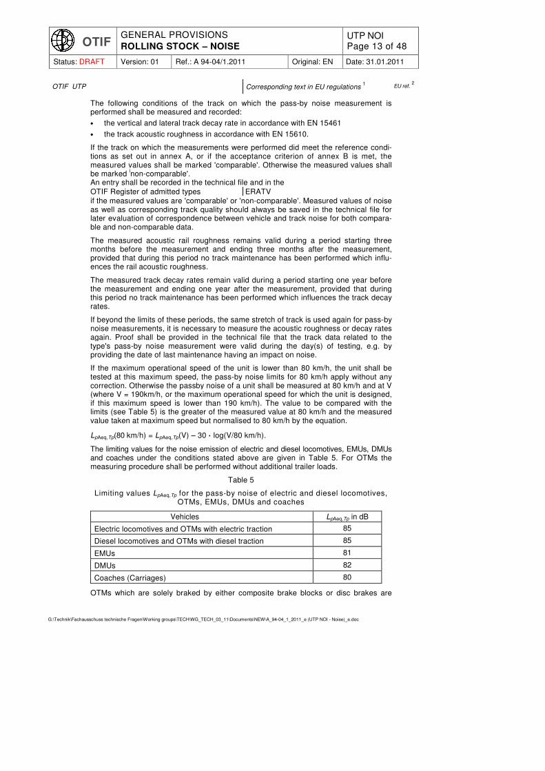
If the maximum operational speed of the unit is lower than 80 km/h, the unit shall be tested at this maximum speed, the pass-by noise limits for 80 km/h apply without any correction. Otherwise the passby noise of a unit shall be measured at 80 km/h and at V (where V = 190km/h, or the maximum operational speed for which the unit is designed, if this maximum speed is lower than 190 km/h). The value to be compared with the limits (see Table 5) is the greater of the measured value at 80 km/h and the measured value taken at maximum speed but normalised to 80 km/h by the equation.
LpAeq,Tp(80 km/h) = LpAeq,Tp(V) – 30 · log(V/80 km/h).
The limiting values for the noise emission of electric and diesel locomotives, EMUs, DMUs and coaches under the conditions stated above are given in Table 5. For OTMs the measuring procedure shall be performed without additional trailer loads.
Table 5
Limiting values LpAeq,Tp for the pass-by noise of electric and diesel locomotives, OTMs, EMUs, DMUs and coaches
Vehicles LpAeq,Tp in dB
Electric locomotives and OTMs with electric traction 85
Diesel locomotives and OTMs with diesel traction 85
EMUs 81
DMUs 82
Coaches (Carriages) 80
OTMs which are solely braked by either composite brake blocks or disc brakes are

OTIF GENERAL PROVISIONS
ROLLING STOCK – NOISE UTP NOI Page 14 of 48
Status: DRAFT Version: 01 Ref.: A 94-04/1.2011 Original: EN Date: 31.01.2011
G:\Technik\Fachausschuss technische Fragen\Working groups\TECH\WG_TECH_03_11\Documents\NEW\A_94-04_1_2011_e (UTP NOI - Noise)_e.doc
OTIF UTP Corresponding text in EU regulations 1 EU ref.
2
deemed to comply with the pass-by noise level requirements in table 5 without measur-ing. This applies also if these vehicles are equipped with composite scrubbers.
4.2.3 INTERIOR NOISE OF LOCOMOTIVES, MULTIPLE UNITS AND COACHES FITTED WITH A CAB
As addressed in clause 2.1.5, OTMs shall be assessed against the requirements for locomotives.
The interior noise level of passenger vehicles is not considered to be a basic parame-ter. However, the noise level within the driver's cab is an important issue. Noise levels in the cab must be kept as low as possible, by limiting the noise at the source and by appropriate additional measures (acoustic insulation, sound absorption). The limiting values are defined in Table 6. For OTMs the measuring procedure shall be performed without additional trailer loads.
Measurements shall be made in accordance with annex F.
Table 6
Limiting values LpAeq,T for the noise within the driver's cab of electric and diesel locomo-tives, OTMs, EMUs, DMUs and coaches fitted with a driver’s cab
Noise within the driver’s cab LpAeq,T in dB
Measurement time interval T, in seconds
Standstill (during external acoustic warning with the maximum sound pressure of the horn, but less than 125 dB(A) at 5 m ahead of the vehicle in 1,6 m height above top of rail)
95 3
Maximum speed, applicable for speeds less than 190 km/h. (open country without interior and exterior warnings)
78 60
Note: This table applies to the driver’s cab.
National rules notified according to APTU Article 12 of the admitting Contracting State(s)
In any event, Directive 2003/10/EC of the European Parliament and the Council of 6 February 2003
on the minimum health and safety requirements regarding the exposure of workers to the risks arising from physical agents (noise) has to be applied by railway undertakings and their staff, but the compliance with
those rules Directive 2003/10/EC
does not concern the
technical admission EC verification
of rolling stock.
4.3 FUNCTIONAL AND TECHNICAL SPECIFICATIONS OF THE INTER-FACES
This
UTP TSI
is part of the framework of
UTPs TSIs
which set requirements to the conventional rail rolling stock subsystem.
60
OTIF GENERAL PROVISIONS
ROLLING STOCK – NOISE UTP NOI Page 15 of 48
Status: DRAFT Version: 01 Ref.: A 94-04/1.2011 Original: EN Date: 31.01.2011
G:\Technik\Fachausschuss technische Fragen\Working groups\TECH\WG_TECH_03_11\Documents\NEW\A_94-04_1_2011_e (UTP NOI - Noise)_e.doc
OTIF UTP Corresponding text in EU regulations 1 EU ref.
2
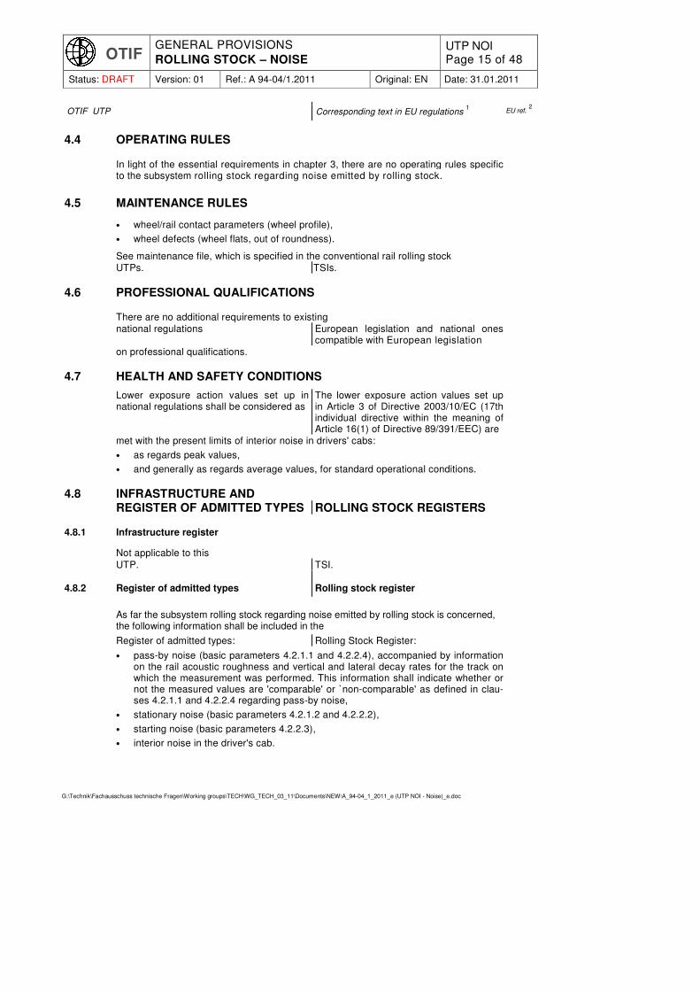
4.4 OPERATING RULES
In light of the essential requirements in chapter 3, there are no operating rules specific to the subsystem rolling stock regarding noise emitted by rolling stock.
4.5 MAINTENANCE RULES
• wheel/rail contact parameters (wheel profile),
• wheel defects (wheel flats, out of roundness).
See maintenance file, which is specified in the conventional rail rolling stock
UTPs. TSIs.
4.6 PROFESSIONAL QUALIFICATIONS
There are no additional requirements to existing
national regulations European legislation and national ones compatible with European legislation
on professional qualifications.
4.7 HEALTH AND SAFETY CONDITIONS
Lower exposure action values set up in national regulations shall be considered as
The lower exposure action values set up in Article 3 of Directive 2003/10/EC (17th individual directive within the meaning of Article 16(1) of Directive 89/391/EEC) are
met with the present limits of interior noise in drivers' cabs:
• as regards peak values,
• and generally as regards average values, for standard operational conditions.
4.8 INFRASTRUCTURE AND
REGISTER OF ADMITTED TYPES ROLLING STOCK REGISTERS
4.8.1 Infrastructure register
Not applicable to this
UTP. TSI.
4.8.2 Register of admitted types Rolling stock register
As far the subsystem rolling stock regarding noise emitted by rolling stock is concerned, the following information shall be included in the
Register of admitted types: Rolling Stock Register:
• pass-by noise (basic parameters 4.2.1.1 and 4.2.2.4), accompanied by information
on the rail acoustic roughness and vertical and lateral decay rates for the track on which the measurement was performed. This information shall indicate whether or not the measured values are 'comparable' or `non-comparable' as defined in clau-ses 4.2.1.1 and 4.2.2.4 regarding pass-by noise,
• stationary noise (basic parameters 4.2.1.2 and 4.2.2.2),
• starting noise (basic parameters 4.2.2.3),
• interior noise in the driver's cab.
OTIF GENERAL PROVISIONS
ROLLING STOCK – NOISE UTP NOI Page 16 of 48
Status: DRAFT Version: 01 Ref.: A 94-04/1.2011 Original: EN Date: 31.01.2011
G:\Technik\Fachausschuss technische Fragen\Working groups\TECH\WG_TECH_03_11\Documents\NEW\A_94-04_1_2011_e (UTP NOI - Noise)_e.doc
OTIF UTP Corresponding text in EU regulations 1 EU ref.
2
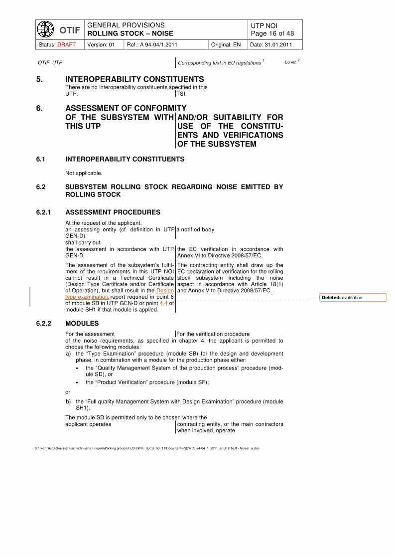
5. INTEROPERABILITY CONSTITUENTS
There are no interoperability constituents specified in this
UTP. TSI.
6. ASSESSMENT OF CONFORMITY OF THE SUBSYSTEM WITH
THIS UTP AND/OR SUITABILITY FOR USE OF THE CONSTITU-ENTS AND VERIFICATIONS OF THE SUBSYSTEM
6.1 INTEROPERABILITY CONSTITUENTS
Not applicable.
6.2 SUBSYSTEM ROLLING STOCK REGARDING NOISE EMITTED BY ROLLING STOCK
6.2.1 ASSESSMENT PROCEDURES
At the request of the applicant,
an assessing entity (cf. definition in UTP GEN-D)
a notified body
shall carry out
the assessment in accordance with UTP GEN-D.
The assessment of the subsystem’s fulfil-ment of the requirements in this UTP NOI cannot result in a Technical Certificate (Design Type Certificate and/or Certificate of Operation), but shall result in the Design type examination report required in point 6 of module SB in UTP GEN-D or point 4.4 of module SH1 if that module is applied.
the EC verification in accordance with Annex VI to Directive 2008/57/EC.
The contracting entity shall draw up the EC declaration of verification for the rolling stock subsystem including the noise aspect in accordance with Article 18(1) and Annex V to Directive 2008/57/EC.
6.2.2 MODULES
For the assessment For the verification procedure
of the noise requirements, as specified in chapter 4, the applicant is permitted to choose the following modules:
a) the “Type Examination” procedure (module SB) for the design and development phase, in combination with a module for the production phase either:
• the “Quality Management System of the production process” procedure (mod-ule SD), or
• the “Product Verification” procedure (module SF);
or
b) the “Full quality Management System with Design Examination” procedure (module SH1).
The module SD is permitted only to be chosen where the
applicant operates contracting entity, or the main contractors when involved, operate
Deleted: evaluation

OTIF GENERAL PROVISIONS
ROLLING STOCK – NOISE UTP NOI Page 17 of 48
Status: DRAFT Version: 01 Ref.: A 94-04/1.2011 Original: EN Date: 31.01.2011
G:\Technik\Fachausschuss technische Fragen\Working groups\TECH\WG_TECH_03_11\Documents\NEW\A_94-04_1_2011_e (UTP NOI - Noise)_e.doc
OTIF UTP Corresponding text in EU regulations 1 EU ref.
2
a quality management system for manufacture, final production, inspection and testing, approved and surveyed by
a competent authority, a suitable body or a “notified body” in a Contracting State of its choice.
a Notified Body of his/their choice.
The module SH1 is permitted only to be chosen where the applicant operates contracting entity, or the main contractors
when involved,
a quality management system for design, manufacture, final production inspection and testing, approved and surveyed by
a competent authority, a suitable body or a “notified body” in a Contracting State of its choice.
a notified body of their choice.
6.2.3 ASSESSMENT (VERIFICATION) METHODS SPECIFIC TO NOISE ASPECTS OF ROLLING STOCK
6.2.3.1 Introduction
Notwithstanding the exemptions as described in this section, by default all new types need to be assessed in compliance with the requirements specified in Section 4 of this
UTP TSI
Instead of the test procedures as set out in Section 4 of this
UTP, it is TSI, it may be
permitted to substitute some or all of the tests by a simplified evaluation method. The eligibility criteria and requirements associated to the simplified evaluation method are set out in this section.
The simplified evaluation method consists of acoustically comparing the type under assessment to an existing type with documented noise characteristics compliant with the noise
UTP; TSI;
the latter is further referred to as the reference type.
It is permitted to substitute noise testing by a simplified evaluation, if the type under assessment is comparable to a reference type which has been tested in compliance with one of the following:
a) Section 4 of this
UTP TSI
and for which the pass-by noise results are marked ‘comparable’, or
b) in compliance with Section 4 of the TSI CR ‘rolling stock— noise’ in the version adopted by Commission Decision 2006/66/EC
5.
The following units are eligible for a simplified evaluation:
a) Different formations of multiple units,
b) Renewed or upgraded units in accordance with point 7.6 of this
UTP, TSI,
c) New units which are largely based on an existing design (same vehicle family).
For the units under assessment for simplified evaluation, the proof of conformity shall include a detailed description of the noise relevant changes compared to the reference type. From this description, a simplified evaluation (see points 6.2.3.2 and 6.2.3.3) shall
5 EU Official Journal L37, 08.02.2006, p. 1-49
Formatted: UTPnormal+space
above
Formatted: UTPnormal+space
above
Formatted: UTPnormal,
Adjust space between Latin
and Asian text, Adjust space
between Asian text and
Formatted: UTPnormal+space
above, Adjust space between
Latin and Asian text, Adjust
space between Asian text and
numbers
Formatted: Indent: Left:
0.63 cm
Formatted: UTPnormal,
Indent: Left: 0.63 cm, Adjust
space between Latin and Asian
text, Adjust space between
Asian text and numbers
Formatted: UTPnormal+space
above Zchn
Formatted: UTPnormal+space
above, Indent: Left: 0 cm,
Hanging: 0.63 cm, Numbered
+ Level: 1 + Numbering Style:
a, b, c, … + Start at: 1 +
Alignment: Left + Aligned at:
0.63 cm + Tab after: 1.88 cm
+ Indent at: 1.88 cm, Tabs:
Not at 1.88 cm
Formatted: UTPnormal+space
above Zchn
Formatted: UTPnormal+space
above Zchn, Font: Not Italic,
Font color: Auto
Formatted: Font: Not Italic,
Font color: Auto
Formatted: Font: Not Italic
Formatted: Indent: Left:
0.63 cm
Formatted: Font: Not Italic
Formatted: UTPnormal+space
above, Indent: Left: 0 cm,
Hanging: 0.63 cm, Numbered
+ Level: 1 + Numbering Style:
a, b, c, … + Start at: 1 +
Alignment: Left + Aligned at:
0.32 cm + Tab after: 1.56 cm
+ Indent at: 1.56 cm, Adjust
space between Latin and Asian
text, Adjust space between
Asian text and numbers, Tabs:
Not at 1.56 cm

OTIF GENERAL PROVISIONS
ROLLING STOCK – NOISE UTP NOI Page 18 of 48
Status: DRAFT Version: 01 Ref.: A 94-04/1.2011 Original: EN Date: 31.01.2011
G:\Technik\Fachausschuss technische Fragen\Working groups\TECH\WG_TECH_03_11\Documents\NEW\A_94-04_1_2011_e (UTP NOI - Noise)_e.doc
OTIF UTP Corresponding text in EU regulations 1 EU ref.
2
be performed to identify the differences in terms of expected noise emission, of the noise cases specified in point 4.2 between the reference unit and the unit under as-sessment.
The simplified evaluation may be used on a unit for each of the individual noise cases autonomously: stationary noise, starting noise, cab-noise and pass-by noise.
6.2.3.2 Simplified evaluation for locomotives, multiple units, coaches and OTMs
The simplified evaluation shall prove that the unit under assessment complies with the applicable noise levels as set out in this
UTP, TSI,
for those noise cases for which the simplified evaluation is used.
The simplified evaluation on a unit shall consists of providing evidence to show that the acoustically relevant systems and characteristics are either identical to those of the reference type, or such that they will not result in higher noise emission of the unit under assessment. The simplified evaluation can either be a calculation, or simplified measurement (e.g. sound power of noise sources), or a combination of both. Noise relevant systems which differ from the reference type shall be identified in the technical file.
6.2.3.3 Simplified evaluation for freight wagons
For upgraded or renewed wagons, also see clause 7.6.1. In case additional conformity assessment is needed and where table 7 is complied with, the simplified evaluation method is permitted to be used for upgraded or renewed freight wagons.
For new wagons: in cases where table 7 is complied with, the simplified evaluation method is permitted to be used for freight wagons.
Table 7
List of noise relevant parameters for freight wagons and their permitted variation from a 'reference type' configuration
Unit parameter Permitted variation Applies for:
Stationary noise
Pass-by noise
Max unit speed Up to 10 km/h increase allowed compared to the reference type
— +
Type of wheel Allowed if less noisy than the reference type's wheel type (acoustic characterisa-tion of the wheels as set out in Annex E of EN 13979-1)
— +
Number of axles per unit length (related to either the length of the wagon or the number of wheelsets
Allowed, if lower that reference type
— +
Tare weight Change ± 5% allowed compared to the reference type
— +
Brake system No change allowed compared to the reference type
— +
... [1]

OTIF GENERAL PROVISIONS
ROLLING STOCK – NOISE UTP NOI Page 19 of 48
Status: DRAFT Version: 01 Ref.: A 94-04/1.2011 Original: EN Date: 31.01.2011
G:\Technik\Fachausschuss technische Fragen\Working groups\TECH\WG_TECH_03_11\Documents\NEW\A_94-04_1_2011_e (UTP NOI - Noise)_e.doc
OTIF UTP Corresponding text in EU regulations 1 EU ref.
2
Class of wagon (e.g. tank, hopper, van, platform)
No change of class allowed compared to the reference type
+ +
Auxiliary equipment No restriction + —
If the simplified evaluation is permitted to be used:
• The pass-by noise levels as set out in clause 4.2.1.1 are deemed to be compliant without testing.
• For stationary noise, the simplified evaluation shall consists of providing evidence to show that the acoustically relevant systems and characteristics are either identi-cal to those of the reference type, or such that they will not result in higher noise emission of the unit under assessment. The simplified evaluation can either be a calculation, or simplified measurement (e.g. sound power of noise sources), or a combination of both. Noise relevant systems which differ from the reference type shall be identified in the technical file.
6.2.4 UNITS CERTIFIED AGAINST THE EU HIGH-SPEED ROLLING STOCK TSI (HS RST TSI)
UNITS REQUIRING EC CERTIFI-CATION AGAINST THE HS RST TSI AND AGAINST THIS TSI
When a unit has been positively assessed against the HS RST TSI, it is deemed to comply with the requirements in this
UTP TSI
without further checks,
provided the vehicle is not subject to any In this case, the applicant may issue its EC declaration without further evaluation.
This is only permitted if there are no
derogations relating to noise aspects.
7. IMPLEMENTATION
7.1 GENERAL
The implementation of the
UTPs TSIs
must take into consideration the overall migration of the conventional rail network towards full interoperability.
In order to support this migration, the
UTPs TSIs
allow for staged, gradual application and coordinated implementation with other
UTPs. TSIs.
7.2 UTP REVISION TSI REVISION
The Committee of Technical Experts shall be responsible for reviewing and updating this and related UTPs
In conformity with article 6(2) of Directive 2008/57/EC, the Agency shall be re-sponsible for preparing the review and updating of TSIs and making appropriate recommendations to the Committee referred to in Article 21 of this directive (also referred to as RISCommittee)
in order to take account of developments in technology or social requirements. In addition, the progressive adoption and revision of other
UTPs TSIs

OTIF GENERAL PROVISIONS
ROLLING STOCK – NOISE UTP NOI Page 20 of 48
Status: DRAFT Version: 01 Ref.: A 94-04/1.2011 Original: EN Date: 31.01.2011
G:\Technik\Fachausschuss technische Fragen\Working groups\TECH\WG_TECH_03_11\Documents\NEW\A_94-04_1_2011_e (UTP NOI - Noise)_e.doc
OTIF UTP Corresponding text in EU regulations 1 EU ref.
2
may also impact this
UTP. TSI.
Proposed changes to this
UTP TSI
shall be subject to rigorous review and updated
UTPs TSIs
will be published on an indicative periodic basis of 3 years.
The Secretary General shall be notified of any innovative solutions under considera-tion in order to determine its future inclu-sion in the UTP.
In the first revision, the Committee of Technical Experts should consider
In any case the EC will deliver to the "RIS Committee", at the latest by 23 June 2013, a report and, if needed, a proposal for revising this TSI with regard to
the following issues:
1. an assessment of the implementation of the
UTP TSI
in particular costs and benefits;
2. the use of a continuous curve of limiting values LpAeq,Tp for the pass-by noise of freight wagons as a function of APL (axles per length), provided that it does not prevent technical innovation, in particular for rakes of wagons;
3. the second step pass-by noise limit values for wagons, locomotives, multiple units and coaches (see point 7.2), according to the results of comparable noise meas-urement campaigns, taking into account in particular technical progress and avail-able technologies for both track and rolling stock and cost-benefit analyses;
4. a possible second-step starting noise limit values for diese) locomotives and multiple units;
5. the inclusion of infrastructure into the scope of the
UTP Noise TSI Noise
in coordination with the
UTP Infrastructure TSI Infrastructure
in coordination with the (future) particular costs and benefits;
6. the inclusion of infrastructure into the
UTP Noise TSI Noise
of a monitoring scheme for wheel defects. Wheel defects have an impact on noise emission.
7.3 A TWO STEP APPROACH
It is recommended that in the case of new rolling stock to be ordered after
5 years after the entry into force of this UTP
23 June 2016, or authorised to be placed into service after 23 June 2018,
points 4.2.1.1 and 4.2.2.4 of this
UTP TSI
are applied with a reduction of 5 dB except for DMUs and EMUS. For both latter cases the reduction is 2 dB. This recommendation will serve only as a basis for revis-ing points 4.2.1.1 and 4.2.2.4 in the context of the
UTP TSI
revision process mentioned in point 7.2.

OTIF GENERAL PROVISIONS
ROLLING STOCK – NOISE UTP NOI Page 21 of 48
Status: DRAFT Version: 01 Ref.: A 94-04/1.2011 Original: EN Date: 31.01.2011
G:\Technik\Fachausschuss technische Fragen\Working groups\TECH\WG_TECH_03_11\Documents\NEW\A_94-04_1_2011_e (UTP NOI - Noise)_e.doc
OTIF UTP Corresponding text in EU regulations 1 EU ref.
2
7.4 RETROFITTING PROGRAMME FOR NOISE REDUCTION
There are no retrofitting requirements in this UTP. However, a Contracting State may adopt a mandatory retrofitting pro-gramme for vehicles registered in their National Vehicle Register (NVR) in order that those vehicles will meet the require-ments of this UTP within a specific time-scale.
Given the long life-cycle of railway vehi-cles it is also necessary to take measures on the existing fleet of rolling stock, with priority for freight wagons, to foster a noticeable reduction of the perceived noise level within a reasonable time period. The Commission will take initia-tives to discuss options for retrofitting of freight wagons with the relevant stake-holders to achieve a general agreement with the industry.
7.5 APPLICATION OF THIS UTP TSI TO NEW ROLLING STOCK
The specifications provided in this
UTP TSI
apply to all new rolling stock within the scope of this UTP. TSI.
7.5.1 Starting noise 7.5.2
The starting noise limits are permitted to be raised by 2 dB for all DMUs, with an engine power greater than 500 kW/engine, authorised to be placed into service during a transitional period which ends
2 years after the entry into force of this UTP. 23 June 2011.
7.5.2 Exceptions for national, bilateral, multilateral or multinational agreements 7.5.4
7.5.2.1 Existing agreements 7.5.4.1
Existing agreements notified to the Secre-tary General between Contracting States and agreements with other States having a track gauge of 1520 mm shall remain in force until the Committee of Technical Experts decides otherwise.
Where notified agreements contain re-quirements related to noise, these agree-ments remain permitted until the neces-sary measures are taken including EU level agreements related to this TSI with Russian Federation and all the other CIS countries having a border with the EU.
7.5.2.2 Future agreements or modification of existing agreements 7.5.4.2
Any future agreement or modification of existing agreements shall take into account
COTIF regulations EU legislation
and, in particular this
UTP TSI.
as far as applicable,
Before their conclusion, Contracting States shall notify the Secretary General of
Member States shall notify the Commis-sion with
such agreements/modifications.
The Committee of Technical Experts will examine their compatibility with the COTIF regulations, including this UTP, and will include, for example, possible specific cases or transitional measures the next time this UTP will be revised.

OTIF GENERAL PROVISIONS
ROLLING STOCK – NOISE UTP NOI Page 22 of 48
Status: DRAFT Version: 01 Ref.: A 94-04/1.2011 Original: EN Date: 31.01.2011
G:\Technik\Fachausschuss technische Fragen\Working groups\TECH\WG_TECH_03_11\Documents\NEW\A_94-04_1_2011_e (UTP NOI - Noise)_e.doc
OTIF UTP Corresponding text in EU regulations 1 EU ref.
2
7.6 APPLICATION OF THIS
UTP UTP
TO EXISTING ROLLING STOCK
7.6.1 Renewal or upgrading of existing freight wagons
In the case of renewal or upgrading of freight wagons
according to ATMF Article 10 § 11, the Contracting State has
the Member State, has according to Article 20 of Directive 2008/57/EC
to decide if a new
technical admission authorisation for placing into service
is needed.
If the performance of the brake system of this wagon is changed by the renewal or upgrading and if a new
technical admission authorisation for placing into service
is needed, the requirement is that the pass-by level of this wagon shall comply with the relevant level indicated in Table 1 of point 4.2.1.1.
If a wagon during renewal or upgrading is being equipped (or is already equipped) with composite blocks and without adding additional noise sources to the wagon, it shall be assumed without testing that the values of point 4.2.1.1 are fulfilled.
An upgrading for noise emission reduction only is not mandatory, but if upgrading is done for another reason it shall be demonstrated that renewal or upgrading does either not increase pass-by noise levels, or when increased remain within the limits which are specified in this
UTP. TSI.
For stationary noise, it shall be demonstrated that the stationary noise levels do either not increase, or when increased remain within the limits which are specified in this
UTP. TSI.
As an alternative to full vehicle measurement, the demonstration of compliance of a unit is permitted to be performed by an evaluation under the conditions as defined in clause 6.2.3 of this
UTP. TSI.
In this case the unit before upgrade shall act as the reference unit.
7.6.2 Renewal or upgrading of locomotives, multiple units, coaches and OTMs
lt shall be demonstrated that the noise levels of renewed or upgraded units are either not increased, or when increased remain within the limits which are specified in this
UTP. TSI.
The demonstration of compliance of a unit can, as an alternative to full vehicle meas-urement, also be done by an evaluation under the conditions as defined in clause 6.2.3 of this
UTP. TSI.
In this case the unit before upgrade shall act as the reference unit.
7.7 SPECIFIC CASES
The specific cases included in UTP Noise shall apply in common to EU and OTIF.
7.7.1 Introduction
The following special provisions are permitted in the specific cases below.
These specific cases belong to two categories: the provisions apply either permanently

OTIF GENERAL PROVISIONS
ROLLING STOCK – NOISE UTP NOI Page 23 of 48
Status: DRAFT Version: 01 Ref.: A 94-04/1.2011 Original: EN Date: 31.01.2011
G:\Technik\Fachausschuss technische Fragen\Working groups\TECH\WG_TECH_03_11\Documents\NEW\A_94-04_1_2011_e (UTP NOI - Noise)_e.doc
OTIF UTP Corresponding text in EU regulations 1 EU ref.
2
(case P), or temporarily (case T). In temporary cases, it is recommended that the
Contracting States which are not subject to EU law
Member States
concerned should
fully apply the specifications set out in chapter 4 and the provisions in section 7.5 and 7.6 by 2 years (case T1) and by 10 years (case T2) after the entry into force of this UTP, at the latest. Contracting States which are subject to EU law shall apply the EU recommendations.
conform with the relevant subsystem either by 2010 (case T1), an objective set out in Decision 1692/96/EC of the Euro-pean Parliament and of the Council of 23 July 1996 on Community guidelines for the development of the trans-European transport network, or by 2020 (case T2).
7.7.2 List of specific cases
7.7.2.1 Limit for stationary noise, "strictIy for use on the UK and Ireland networks only"
Category P - permanent
Table 8
Limiting values LpAeq,T for the stationary noise of DMUs
Vehicles LpAeq,T in dB
DMUs 77
7.7.2.2 Finland
Category P – permanent
The application of national technical rules instead of the requirements in this TSI is permit-ted for third countries' rolling stock to be used on the Finnish 1524 mm network in traffic between Finland and third countries’ 1520 mm network.
Category T1 – temporary
In the territory of Finland, the limits for stationary noise in point 4.2.1.2 shall not be applied to wagons equipped with a diesel aggregate for electrical power supply higher than 100 kW when the aggregate is used. In this case the stationary noise limit may be raised by 7 dB due to the temperature range down to - 40 °C together with freezing and icy conditions.
7.2.2.3 Limits for starting noise, "strictly for use on the UK and Ireland networks only"
Category P – permanent
Table 9
Limiting values LpAFmax for the starting noise of electric locomotives, diesel locomotives and DMUs
Vehicles LpAeq,T in dB
Electric locomotives less than 4500 kW at the rail wheel 84
Diesel locomotives less than 2000 kW at the engine output shaft 89
DMUs P < 500 kW/engine 85
7.7.2.4 Limits for pass-by noise for freight wagons, in Finland, Norway, Estonia, Latvia and Lithuania
Category T1 – temporary
The noise emission limits for freight wagons are not valid for Finland, Norway, Estonia,

OTIF GENERAL PROVISIONS
ROLLING STOCK – NOISE UTP NOI Page 24 of 48
Status: DRAFT Version: 01 Ref.: A 94-04/1.2011 Original: EN Date: 31.01.2011
G:\Technik\Fachausschuss technische Fragen\Working groups\TECH\WG_TECH_03_11\Documents\NEW\A_94-04_1_2011_e (UTP NOI - Noise)_e.doc
OTIF UTP Corresponding text in EU regulations 1 EU ref.
2
Latvia and Lithuania. The reason for this is the safety aspects under Nordic winter conditions. This specific case is valid until the functional specification and assessment method for composite brake blocks are incorporated in the revised version of the WAG TSI.
That does not preclude freight wagons from other
Contracting States EU Member States
from operating in those Nordic and Baltic States.
7.7.2.5 Specific case for Greece
Category T1 – temporary: Rolling stock for track gauge 1000 mm or less.
7.7.2.6 Specific case for Estonia, Latvia and Lithuania
Category T1 – temporary
The noise emission limits for all rolling stock (locomotives, coaches, EMUs and DMUs) are not valid for Estonia, Latvia and Lithuania until the revision of
the TSI Noise. this TSI.
In the meantime, measurement cam-paigns will be carried out in these States; the revision of this TSI shall take into account the results of these campaigns.
7.7.2.7 Specific cases for non-EU OTIF Contracting States
Specific cases for Contracting States which are not Member States of the European Union will be included in this UTP when they have been negotiated and adopted by the Committee of Technical Experts.

OTIF GENERAL PROVISIONS
ROLLING STOCK – NOISE UTP NOI Page 25 of 48
Status: DRAFT Version: 01 Ref.: A 94-04/1.2011 Original: EN Date: 31.01.2011
G:\Technik\Fachausschuss technische Fragen\Working groups\TECH\WG_TECH_03_11\Documents\NEW\A_94-04_1_2011_e (UTP NOI - Noise)_e.doc
OTIF UTP Corresponding text in EU regulations 1 EU ref.
2
ANNEX A: REFERENCE TRACK DEFINITION
The reference track shall comply with the following requirements:
A.1 RAIL ACOUSTIC ROUGHNESS OF THE TEST TRACK
The condition of the rail acoustic roughness shall be considered suitable for compara-ble measurements if the one-third octave band roughness spectra assessed according to EN15610 throughout the test section fulfil the following upper limit taking into ac-count, if necessary, the flexibility process described in Annex B. The wavelength bandwidth should be at least 0,003 m to 0,10 m (0,3 cm to 10,0 cm corresponding to Figure A.1).
Figure A.1
Upper limit curve for the acoustic rail roughness
-11,0 -10,4 -9,8 -9,2 -8,6 -8,0 -7,4 -6,8 -6,2 -5,6 -5,0
-3,2 -1,1
0,9 2,9
4,9 7,0
9,0
11,0 13,0
15,0 17,1
-15,0
-10,0
-5,0
0,0
5,0
10,0
15,0
20,0
0,0
03
0,0
04
0,0
05
0,0
06
0,0
08
0,0
10
0,0
13
0,0
16
0,0
20
0,0
25
0,0
32
0,0
40
0,0
50
0,0
63
0,0
80
0,1
00
0,1
25
0,1
60
0,2
00
0,2
50
0,3
15
0,4
00
0,5
00
2
1
re 1
µm
3
Key: 1 = 1/3 octave band roughness level, dB
2 = wavelength, m
3 = UTP upper limit, 1/3 octave band roughness level, dB
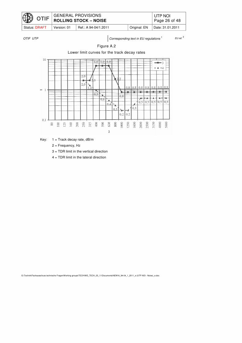
A.2 DYNAMIC PROPERTIES OF THE TEST TRACK
The condit ion of the dynamic properties of the track shall be considered suitable for comparable measurements if the one-third octave band track decay rates spectra measured according to EN15461 throughout the test section fulfil the
following lower limits:
OTIF GENERAL PROVISIONS
ROLLING STOCK – NOISE UTP NOI Page 26 of 48
Status: DRAFT Version: 01 Ref.: A 94-04/1.2011 Original: EN Date: 31.01.2011
G:\Technik\Fachausschuss technische Fragen\Working groups\TECH\WG_TECH_03_11\Documents\NEW\A_94-04_1_2011_e (UTP NOI - Noise)_e.doc
OTIF UTP Corresponding text in EU regulations 1 EU ref.
2
Figure A.2
Lower limit curves for the track decay rates
Key: 1 = Track decay rate, dB/m
2 = Frequency, Hz
3 = TDR limit in the vertical direction
4 = TDR limit in the lateral direction

OTIF GENERAL PROVISIONS
ROLLING STOCK – NOISE UTP NOI Page 27 of 48
Status: DRAFT Version: 01 Ref.: A 94-04/1.2011 Original: EN Date: 31.01.2011
G:\Technik\Fachausschuss technische Fragen\Working groups\TECH\WG_TECH_03_11\Documents\NEW\A_94-04_1_2011_e (UTP NOI - Noise)_e.doc
OTIF UTP Corresponding text in EU regulations 1 EU ref.
2
ANNEX B: SMALL DEVIATION CALCULATION METHOD
Method to assess acceptable small deviations from rail roughness requirements
B.1 PRINCIPLE
The "small deviations" method aims at introducing some flexibility in the conformity assessment of a test track section towards a limit curve of acoustic rail roughness within the frame of constant speed tests. Both the limit curve and the measured acous-tic rail roughness spectra are assumed to be onethird octave band wavelength spec-tra.
Deviations to the track decay rates are not acceptable under the Small deviation calculation method.
The method relies on a calculation of a correction to the measured level based on the effect of any exceeding of a specified spectrum of acoustic rail roughness. The differ-ence between the corrected pass-by noise level and the measured one is then com-pared to an acceptance criterion.
If the criterion is fulfilled, the acoustic impact of the rail roughness deviations is deemed 'small' and the measured pass-by noise level is considered to be comparable.
This method is train speed dependent.
B.2 PROCESSING
B.2.1 GENERATE A 'JUST COMPLIANT' CORRECTED SPECTRUM FROM THE MEASURED ACOUSTIC RAIL ROUGHNESS WAVELENGTH SPECTRUM (STEP 1)
The measured rail acoustic roughness spectra shall be energetically averaged. A corrected spectrum shall be derived from the measured acoustic rail roughness wave-length spectrum and from the limit spectrum according to the following formula:
where
NOTE 1: The corrected acoustic rail roughness spectrum is equivalent to the meas-
ured one except in the wavelength bands where the measured spectrum exceeds the limits.
NOTE 2: The corrected acoustic rail roughness spectrum complies with the limit spectrum
is the is the one-third octave band wavelength spectrum of the measured acoustic rail roughness;
is the one-third octave band wawelength limit spectrum;
is the one-third octave band wavelength limit spectrum of the corrected acoustic rail roughness
OTIF GENERAL PROVISIONS
ROLLING STOCK – NOISE UTP NOI Page 28 of 48
Status: DRAFT Version: 01 Ref.: A 94-04/1.2011 Original: EN Date: 31.01.2011
G:\Technik\Fachausschuss technische Fragen\Working groups\TECH\WG_TECH_03_11\Documents\NEW\A_94-04_1_2011_e (UTP NOI - Noise)_e.doc
OTIF UTP Corresponding text in EU regulations 1 EU ref.
2
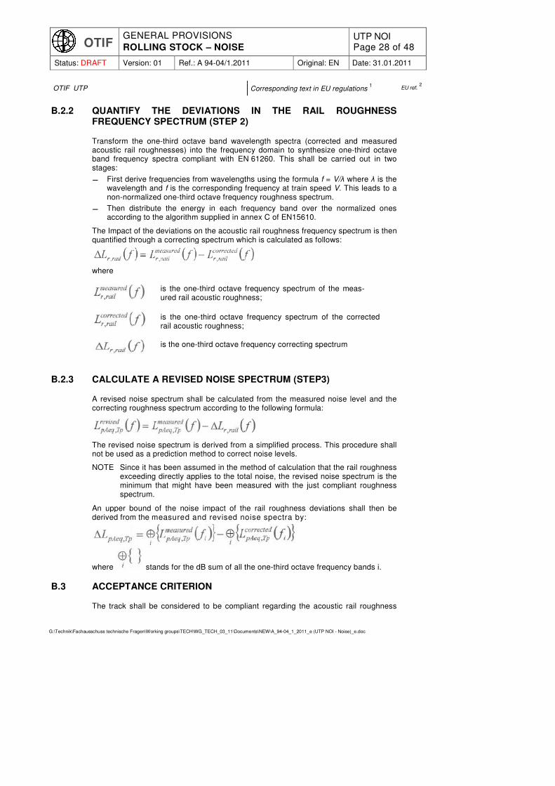
B.2.2 QUANTIFY THE DEVIATIONS IN THE RAIL ROUGHNESS FREQUENCY SPECTRUM (STEP 2)
Transform the one-third octave band wavelength spectra (corrected and measured acoustic rail roughnesses) into the frequency domain to synthesize one-third octave band frequency spectra compliant with EN.61260. This shall be carried out in two stages:
� First derive frequencies from wavelengths using the formula f = V/λ where λ is the wavelength and f is the corresponding frequency at train speed V. This leads to a non-normalized one-third octave frequency roughness spectrum.
� Then distribute the energy in each frequency band over the normalized ones according to the algorithm supplied in annex C of EN15610.
The Impact of the deviations on the acoustic rail roughness frequency spectrum is then quantified through a correcting spectrum which is calculated as follows:
where
B.2.3 CALCULATE A REVISED NOISE SPECTRUM (STEP3)
A revised noise spectrum shall be calculated from the measured noise level and the correcting roughness spectrum according to the following formula:
The revised noise spectrum is derived from a simplified process. This procedure shall not be used as a prediction method to correct noise levels.
NOTE Since it has been assumed in the method of calculation that the rail roughness exceeding directly applies to the total noise, the revised noise spectrum is the minimum that might have been measured with the just compliant roughness spectrum.
An upper bound of the noise impact of the rail roughness deviations shall then be derived from the measured and revised noise spectra by:
where stands for the dB sum of all the one-third octave frequency bands i.
B.3 ACCEPTANCE CRITERION
The track shall be considered to be compliant regarding the acoustic rail roughness
is the one-third octave frequency spectrum of the meas-ured rail acoustic roughness;
is the one-third octave frequency spectrum of the corrected rail acoustic roughness;
is the one-third octave frequency correcting spectrum

OTIF GENERAL PROVISIONS
ROLLING STOCK – NOISE UTP NOI Page 29 of 48
Status: DRAFT Version: 01 Ref.: A 94-04/1.2011 Original: EN Date: 31.01.2011
G:\Technik\Fachausschuss technische Fragen\Working groups\TECH\WG_TECH_03_11\Documents\NEW\A_94-04_1_2011_e (UTP NOI - Noise)_e.doc
OTIF UTP Corresponding text in EU regulations 1 EU ref.
2
spectrum if the noise impact ∆LpAeq,Tp calculated according to step 3 is less than or equal to 1 dB.
This compliance shall be examined for one pass-by at each speed.

OTIF GENERAL PROVISIONS
ROLLING STOCK – NOISE UTP NOI Page 30 of 48
Status: DRAFT Version: 01 Ref.: A 94-04/1.2011 Original: EN Date: 31.01.2011
G:\Technik\Fachausschuss technische Fragen\Working groups\TECH\WG_TECH_03_11\Documents\NEW\A_94-04_1_2011_e (UTP NOI - Noise)_e.doc
OTIF UTP Corresponding text in EU regulations 1 EU ref.
2
ANNEX C: MEASUREMENT DETAILS FOR STATIONARY NOISE MEASUREMENTS
Stationary test
C.1 GENERAL
The measurements shall be carried out only if noise sources are present at standstill with the operating conditions specified under the heading 'Vehicle conditions' in this annex.
C.2 ENVIRONMENTAL CONDITIONS
C.2.1 ACOUSTICAL ENVIRONMENT
In the triangular area between the track and the microphone extending along the track to a distance twice the microphone distance to either side, the test site shall be such that free sound propagation exists. To achieve this result, then:
� the level of the ground surface over this area shall be within +0 m to -2 m, relative to the top of rail;
� this area shall be free of sound absorbing matter (e.g. lying snow, tall vegetation) or reflective covering (e.g. water, ice, tarmac or concrete);
� no person shall be present in this area, and the observer shall be in a position that does not influence the measured sound pressure level significantly;
� the presence of other tracks is permissible in this area as long as the ballast bed height does not exceed the height of the rail surface of the test track.
Additionally, an area around the microphones having a radius which is at least 3 times the measurement distance shall be free of large reflecting objects like barriers, hills, rocks, bridges or buildings.
C.2.2 BACKGROUND SOUND PRESSURE LEVEL
Care shall be taken to ensure that the noise from other sources (for example other vehicles or industrial plants and due to wind) does not influence significantly the measurements.
The maximum value of the LAeq,T where T = 20 sec of background noise over all microphone positions shall be at least 10 dB below the final result (energy-mean of all the measuring positions, see under heading 'Measurement mesh' in this annex) ob-tained when measuring the noise from the unit in the presence of background noise.
C.3 TRACK CONDITIONS
The measurements shall be made on track with ballast bed.
C.4 VEHICLE CONDITIONS
C.4.1 GENERAL
Air management systems, including grilles, filters and fans, shall be clear of any obstruction.
During the measurements, the doors and windows of the unit shall be kept closed.

OTIF GENERAL PROVISIONS
ROLLING STOCK – NOISE UTP NOI Page 31 of 48
Status: DRAFT Version: 01 Ref.: A 94-04/1.2011 Original: EN Date: 31.01.2011
G:\Technik\Fachausschuss technische Fragen\Working groups\TECH\WG_TECH_03_11\Documents\NEW\A_94-04_1_2011_e (UTP NOI - Noise)_e.doc
OTIF UTP Corresponding text in EU regulations 1 EU ref.
2
C.4.2 NORMAL OPERATING CONDITIONS
The measurements shall be carried out in normal operating conditions defined as follows:
All equipment that operates continuously when the unit is stationary shall be operating at normal load, which is the performance at an external temperature of 20°C. For HVAC systems conditioning passenger areas and working places as well as system supplying energy for this function, climate influence parameters shall be set at: wind speed at 3 m/sec, relative humidity at 50 %, 700 W/m
2 energy from sun radiation, one
person per seat and a constant interior temperature of 20°C.
Traction equipment shall be in a stationary thermal condition with cooling equipment working at minimum condition. For units with internal combustion engines, the engine shall idle.
C.5 MEASUREMENT POSITION
C.5.1 MEASUREMENT MESH
Each vehicle (a multiple unit comprises a number of vehicles) shall be divided into equally distributed areas, each having an identical horizontal length Ix between 3 m and 5 m. The length of the vehicle is the distance between couplers or buffers. Each measurement position is located at midlength along the relevant area on both sides of the vehicle. Extra measurement positions shall be taken at the front and rear end of the unit: two microphones located at 60° from the centre of the track, on a half circle having its centre in the midpoint of the unit end (without couplers or buffers) and a radius equal to 7,5 m as illustrated in Figure C.3. In the case of a trailer unit these extra positions shall be measured only at ends which are equipped with a cab.
Each measurement position shall be located at a distance of 7,5 m from the centre line of the track at a height of 1,2 m above top of rail and opposite the centre of the unit.
The microphone axis shall be horizontal and directed perpendicularly to the contour of the unit.
C.5.2 REDUCTION OF THE NUMBER OF MEASUREMENT POSITIONS
Redundant measurements may be omitted, considering that some measurement positions are equivalent (and will lead to similar noise levels), in the following cases:
• If both sides of the unit are identical (axisymmetric or point symmetric) then it is permissible to omit the measurement points on one side of the unit.
• If several vehicles of the same type are present within a multiple unit or a fixed formation train, it is permissible to measure each type of vehicle once.
The reduction of the number of measurement positions shall be justified in the report. Omitted points shall be listed and their assumed equivalent location identified.

OTIF GENERAL PROVISIONS
ROLLING STOCK – NOISE UTP NOI Page 32 of 48
Status: DRAFT Version: 01 Ref.: A 94-04/1.2011 Original: EN Date: 31.01.2011
G:\Technik\Fachausschuss technische Fragen\Working groups\TECH\WG_TECH_03_11\Documents\NEW\A_94-04_1_2011_e (UTP NOI - Noise)_e.doc
OTIF UTP Corresponding text in EU regulations 1 EU ref.
2
Figure C.3
Example of a mesh of measurement positions for the stationary noise measurement of a multiple unit. Each of the vehicle a, b, and c is divided up into equally distributed areas, each having a length equal to la /5, lb /4 and lc /4 of between 3 m and 5 m
respectively.
C.6 MEASURED QUANTITIES
The measured acoustic quantity is LpAeq,T with T = 20 sec.
C.7 TEST PROCEDURE
The unit shall be stationary.
At least three valid measurement samples at each position are required, taken either sequentially at each position or sequentially from position to position. The validity of the measurements shall be assessed against the Background noise level (see under heading 'Background sound pressure level' in this annex) and the acceptable spread of the measurement samples (Where a series of three measurement samples are required, a spread of less than or equal to 3 dB shall be fulfilled for the measurement to be considered as valid. Otherwise, additional measurements shall be made.)
The measurement time interval T shall be at least 20 sec. If, however, as an exception it is not possible to maintain the source of noise at its nominal load for 20 sec, the measurement time interval T may be reduced to a minimum of 5 sec. This reduction shall be specified and justified in the test report.
C.8 DATA PROCESSING
For each set of measurements (one sample at each position), the noise levels
Li
TpAeq ,
measured at all positions i shall be energy averaged as follows to derive a single noise indicator representative of the unit:

OTIF GENERAL PROVISIONS
ROLLING STOCK – NOISE UTP NOI Page 33 of 48
Status: DRAFT Version: 01 Ref.: A 94-04/1.2011 Original: EN Date: 31.01.2011
G:\Technik\Fachausschuss technische Fragen\Working groups\TECH\WG_TECH_03_11\Documents\NEW\A_94-04_1_2011_e (UTP NOI - Noise)_e.doc
OTIF UTP Corresponding text in EU regulations 1 EU ref.
2
⋅= ∑⟩⟨
=
n
i
/LTpAeq
ipAeq,T
tot
i
unit l
lL
1
10, 10lg10
where
Li
TpAeq,is the sound pressure level measured at the measurement point i
n is the number of measurement positions. li is the length associated with the measure point i
∑=
=
n
iitot lL
1
The n measurement positions used in the summation shall correspond to the whole mesh defined under heading `Measurement mesh' in this annex, before any possible reduction (see under heading 'Reduction of the number of measurement positions' in this annex). Where appropriate the noise levels of measured equivalent points shall be assigned to omitted points.
A ⟩⟨ TpAeqLunit
, shall then be produced for each of the three sets of measurements.
The test result shall be the arithmetic mean of the ⟩⟨ TpAeqLunit
, values, rounded to the
nearest integer decibel.
The individual ⟩⟨ TpAeqLunit
, as well as the mean shall be presented in the report.
In addition, the full set of Li
TpAeq , measured at all measurement positions shall be
presented in the report.

OTIF GENERAL PROVISIONS
ROLLING STOCK – NOISE UTP NOI Page 34 of 48
Status: DRAFT Version: 01 Ref.: A 94-04/1.2011 Original: EN Date: 31.01.2011
G:\Technik\Fachausschuss technische Fragen\Working groups\TECH\WG_TECH_03_11\Documents\NEW\A_94-04_1_2011_e (UTP NOI - Noise)_e.doc
OTIF UTP Corresponding text in EU regulations 1 EU ref.
2
ANNEX D: MEASUREMENT DETAILS FOR STARTING NOISE MEASUREMENTS
Acceleration test from standstill
D.1 ENVIRONMENTAL CONDITIONS
D.1.1 ACOUSTICAL ENVIRONMENT
In the triangular area between the track and the microphone extending along the track to a distance twice the microphone distance to either side, the test site shall be such that free sound propagation exists. To achieve this result, then:
� the level of the ground surface over this area shall be within +0 m to -2 m, relative to the top of rail;
� this area shall be free of sound absorbing matter (e.g. snow, tall vegetation) or reflective covering (e.g. water, ice, tarmac or concrete);
� no person shall be present in this area, and the observer shall be in a position that does not influence the measured sound pressure level significantly.
� the presence of other tracks is permissible in this area as long as the ballast bed height does not exceed the height of the rail surface of the test track
Additionally, an area around the microphones having a radius which is at least 3 times the measurement distance on both sides shall be free of large reflecting objects like barriers, hills, rocks, bridges or buildings.
D.1.2 BACKGROUND SOUND PRESSURE LEVEL
Care shall be taken to ensure that the noise from other sources (for example other vehicles or industrial plants and due to wind) does not influence significantly the measurements.
The maximum value of the LAeq,T where T = 20 sec of background noise over all micro-phone positions shall be at least 10 dB below the LpAFmax obtained when measuring the noise from the unit in the presence of background noise.
D.2 TRACK CONDITIONS
The track at the measuring section shall be laid without rail joints (welded rail) and free of visible surface defects such as rail burns or pits and spikes caused by the compres-sion of external material between wheel and rail: no audible impact noise due to welds or loose sleepers should be present.
D.3 VEHICLE CONDITIONS
D.3.1 GENERAL
Air management systems, including grilles, filters and fans, shall be clear of any obstruc-tion.
During the measurements, the doors and windows of the unit shall be kept closed.
The measurements shall be carried out in normal operating conditions defined as fol-lows:
All equipment that operates continuously when the unit is starting shall be operating at
OTIF GENERAL PROVISIONS
ROLLING STOCK – NOISE UTP NOI Page 35 of 48
Status: DRAFT Version: 01 Ref.: A 94-04/1.2011 Original: EN Date: 31.01.2011
G:\Technik\Fachausschuss technische Fragen\Working groups\TECH\WG_TECH_03_11\Documents\NEW\A_94-04_1_2011_e (UTP NOI - Noise)_e.doc
OTIF UTP Corresponding text in EU regulations 1 EU ref.
2
normal load, which is the performance at an external temperature of 20°C. For HVAC systems conditioning passenger areas and working places as well as system supplying energy for this function, climate influence parameters shall be set at: wind speed at 3 m/sec, relative humidity at 50 %, 700 W/m
2 energy from sun
radiation, one person per seat and a constant interior temperature of 20°C.
If the noise of an item of auxiliary equipment contributes significantly to the result and is not repeatable, it shall not be considered part of this measurement. Any part of a measurement that is excluded shall be identified in an LAF(t) plot.
D.3.2 LOADING OR OPERATION CONDITIONS
Tests shall be performed with maximum tractive effort without wheel spin and without macro slip.
If the train under test does not comprise a fixed formation, the hauled load has to be defined and shall be sufficient to ensure that the maximum tractive effort will be devel-oped during the measurement.
When applicable the traction unit shall be at the head of the train.
D.4 MEASUREMENT POSITIONS
For standard acceleration tests the measurement positions shall be located at 7,5 m distance from the centre of the track at 1,2 m height.
One measurement position shall be located at the front measurement cross section, which is defined as being 10 m ahead the front of the unit.
Further measurement positions shall be located along the unit depending on the unit length L (see Figure D.4):
� For units less than or equal to 50 m in length no further measurement positions are needed,
� For units longer than 50 m at least one position at 10 m ahead the centre of the unit shall be used. If the distance between the two measurement positions is greater than 50 m then additional measurement positions are required. The dis-tance D between adjacent measurement positions shall be constant and not greater than 50 m.
Measurement shall be carried out on both sides of the unit. If both sides of the unit are identical (axisymmetric or point symmetric) then it is permissible to omit the measure-ment points on one side of the unit.

OTIF GENERAL PROVISIONS
ROLLING STOCK – NOISE UTP NOI Page 36 of 48
Status: DRAFT Version: 01 Ref.: A 94-04/1.2011 Original: EN Date: 31.01.2011
G:\Technik\Fachausschuss technische Fragen\Working groups\TECH\WG_TECH_03_11\Documents\NEW\A_94-04_1_2011_e (UTP NOI - Noise)_e.doc
OTIF UTP Corresponding text in EU regulations 1 EU ref.
2
Figure D.4
Measurement positions for acceleration tests
Key: 1 = measurement position 2 = additional measurement position for long units
D.5 MEASUREMENT QUANTITY
The measured acoustic quantity is LpAF(t).
D.6 TEST PROCEDURE
Three valid measurement samples at each position are required. The validity of the measurements shall be assessed against the background noise level (see under heading 'Background sound pressure level' in this annex) and the acceptable spread of the measurement samples. (Where a series of three measurement samples are required, a spread of less than or equal to 3 dB shall be fulfilled for the measurement to be considered as valid. Otherwise, additional measurements shall be made.)
The train shall accelerate from standstill up to 30 km/h and then maintain the speed.
The measurement time interval T shall begin when the unit under test starts to move and shall end when it is 10 m past the front measurement cross section.
D.7 DATA PROCESSING
Determine the LpAFmax for each measurement (for each starting event and each meas-urement position).
Calculate the arithmetic average of the three valid measurements at each measure-ment position, rounded to the nearest integer decibel.
The final result is the maximum of these averaged values
OTIF GENERAL PROVISIONS
ROLLING STOCK – NOISE UTP NOI Page 37 of 48
Status: DRAFT Version: 01 Ref.: A 94-04/1.2011 Original: EN Date: 31.01.2011
G:\Technik\Fachausschuss technische Fragen\Working groups\TECH\WG_TECH_03_11\Documents\NEW\A_94-04_1_2011_e (UTP NOI - Noise)_e.doc
OTIF UTP Corresponding text in EU regulations 1 EU ref.
2
ANNEX E: MEASUREMENT DETAILS FOR PASS-BY NOISE MEASUREMENTS
Constant speed test
E.1 ENVIRONMENTAL CONDITIONS
E.1.1 ACOUSTICAL ENVIRONMENT
In the triangular area between the track and the microphone extending along the track to a distance twice the microphone distance to either side, the test site shall be such that free sound propagation exists. To achieve this result, then:
� the level of the ground surface over this area shall be within +0 m to -2 m, relative to the top of rail;
� this area shall be free of other tracks, sound absorbing matter (e.g. snow, tall vegetation) or reflective covering (e.g. water, ice, tarmac or concrete);
� no person shall be present in this area, and the observer shall be in a position that does not influence the measured sound pressure level significantly.
Additionally, an area around the microphones having a radius which is at least 3 times the measurement distance shall be free of large reflecting objects like barriers, hills, rocks, bridges or buildings.
E.1.2 BACKGROUND SOUND PRESSURE LEVEL
Care shall be taken to ensure that the noise from other sources (for example other vehicles or industrial plants and due to wind) does not influence significantly the measurements.
The maximum value of the LAeq,T where T = 20 sec of background noise over all micro-phone positions shall be at least 10 dB below the LpAeq,Tp obtained when measuring the noise from the unit in the presence of background noise. For frequency analysis (only necessary in case the small deviation process is used) this difference shall be at least 10 dB in each frequency band of interest.
E.2 TRACK CONDITIONS
E.2.1 GENERAL
The track on which the measurements are performed shall have a consistent super-structure over a minimum length of twice the microphone distance to either side. This includes geometry of the line, track quality, rail roughness and track decay rates as described in this
UTP. TSI.
E.2.2 GEOMETRY OF THE LINE
The radius of curvature r of the track shall be:
r ≥ 1 000 m for tests at train speed V ≤ 70 km/h;
r ≥ 3 000 m for tests at train speed 70 < V ≤ 120 km/h;
r ≥ 5 000 m for tests at train speeds V > 120 km/h.
Where powered units are tested, the level gradient at the track shall be 5:1000 at the

OTIF GENERAL PROVISIONS
ROLLING STOCK – NOISE UTP NOI Page 38 of 48
Status: DRAFT Version: 01 Ref.: A 94-04/1.2011 Original: EN Date: 31.01.2011
G:\Technik\Fachausschuss technische Fragen\Working groups\TECH\WG_TECH_03_11\Documents\NEW\A_94-04_1_2011_e (UTP NOI - Noise)_e.doc
OTIF UTP Corresponding text in EU regulations 1 EU ref.
2
most.
E.2.3 TRACK SUPERSTRUCTURE
The standard superstructure for the constant speed test is a track with ballast bed and wooden or reinforced concrete sleepers without any type of rail or track shielding (use of rail dampers is accepted to comply with track decay rate limits in this
UTP). TSI).
There shall be no ice, frost, or other frozen water products on the test track. The temperature during measurements is permitted to be below zero degrees Celsius.
The track at the measuring section shall be laid without rail joints (welded rail) and be free of visible surface defects such as rail burns or pits and spikes caused by the compression of external material between wheel and rail: no audible impact noise due to welds or loose sleepers shall be present.
E.3 VEHICLE CONDITIONS
E.3.1 GENERAL
Air management systems, including grilles, filters and fans, shall be clear of any obstruction.
During the measurements, the doors and windows of the unit shall be kept closed.
E.3.2 LOADING
The normal operating conditions for stationary noise measurements apply, as defined in annex C of this
UTP. TSI.
Additionally, for fixed formation units, a minimum tractive effort to maintain a constant speed shall be applied during the pass-by noise measurement. To ensure a steady operating condition, it might be required to operate the unit already a certain time in advance in this operating condition.
Except for locomotives, during the pass-by noise measurements, units shall not be physically loaded beyond what is specified above, e.g. no goods shall be loaded to wagons and no passengers shall be present in passenger units.
If the unit being tested is a locomotive, the hauled load shall be at least two-thirds of the maximum permissible value. For the purposes of this standard, it is permissible to use the maximum tractive effort that can be generated at maximum speed as a proxy for maximum permissible hauled load (see Figure E.5). Where appropriate meters and displays are available within the cab of the locomotive under test, the required testing condition may be ensured by operating the locomotive with an indicated tractive effort of at least two-thirds of the maximum available tractive effort. This condition is permit-ted to be ensured by including an instrumented brake vehicle within the hauled set of vehicles, thus allowing the tractive effort to be controlled precisely during the test period by brake application.
The test report shall describe the state of the traction equipments during the test.

OTIF GENERAL PROVISIONS
ROLLING STOCK – NOISE UTP NOI Page 39 of 48
Status: DRAFT Version: 01 Ref.: A 94-04/1.2011 Original: EN Date: 31.01.2011
G:\Technik\Fachausschuss technische Fragen\Working groups\TECH\WG_TECH_03_11\Documents\NEW\A_94-04_1_2011_e (UTP NOI - Noise)_e.doc
OTIF UTP Corresponding text in EU regulations 1 EU ref.
2
Figure E.5
Example of tractive effort versus train speed for the case of a locomotive
Key: 1 = Tractive effort, F [N] 2 = Train speed, V [km/h] 3 = Tractive effort curve 4 = Simplified resistance curve (straight line) 5 = Maximum tractive effort at maximum speed Vmax
6 = 2/3 of maximum tractive effort at maximum speed Vmax
E.3.3 WHEEL TREAD CONDITIONING
The unit shall be in its normal operating conditions and, for test with constant speed, its wheels shall have run in normal traffic at least 1 000 km on track with normal traffic. The wheel treads shall be as free as possible from irregularities, such as flats. For units with tread brakes or scrubber (tread cleaning brakes) the block/tread pair shall be in a run-in condition where block and tread have bedded in sufficiently. Before starting the pass by measurements (typically just before starting the measurements, but not more than 24 hours before starting the measurements} such units shall be braked to standstill two times. Braking shall start at 80 km/h or at the maximum unit speed in the case where it is lower than 80 km/h. The unit shall be braked until a complete stop with a deceleration which is typical in normal operation, but which ensures that no wheel flats are generated.
E.3.4 TRAIN COMPOSITION (ADJACENT VEHICLES)
Noise from other parts of the train shall not influence the measurements of the unit(s) under test. Therefore, for the measurement of a trailed unit, there shall be an acoustically neutral vehicle on one side of at least two units under test, and no vehicle or an acoustically neutral vehicle on the other side. For the measurement of locomotives the adjacent vehicle shall be acoustically neutral.
An adjacent vehicle shall be considered to be acoustically neutral if:
� either it is a vehicle of the same type as the unit(s) under test,
� or the LpAeq,Tp1 is no more than 2,0 dB greater than LpAeq,Tp where the passing times

OTIF GENERAL PROVISIONS
ROLLING STOCK – NOISE UTP NOI Page 40 of 48
Status: DRAFT Version: 01 Ref.: A 94-04/1.2011 Original: EN Date: 31.01.2011
G:\Technik\Fachausschuss technische Fragen\Working groups\TECH\WG_TECH_03_11\Documents\NEW\A_94-04_1_2011_e (UTP NOI - Noise)_e.doc
OTIF UTP Corresponding text in EU regulations 1 EU ref.
2
Tp1 and Tp are indicated in Figure E.6 (for this evaluation, round the values to one
decimal place).
This condition shall be verified and documented at least once for each tested speed.
Figure E.6
Passing time for assessing acoustic neutrality of adjacent vehicle(s)
E.4 MEASUREMENT POSITIONS
The measurement position shall be located at a distance of 7,5 m from the centre line of the track at a height of 1,2 m above top of rail.
Measurement shall be carried out on both sides of the unit. If both sides of the unit are identical (axisymmetric or point symmetric) then it is permissible to omit the measure-ment points on one side of the unit.
E.5 MEASURED QUANTITIES
The basic measured acoustic quantities are LpAeq,Tp train speed and pass-by time Tp. If required due to the use of the small deviations method as described in annex B of this
UTP, TSI,
the frequency spectrum also needs to be determined.
E.6 TEST PROCEDURE
A series of at least three measurements shall be made at each measurement position and for each measurement condition (one vehicle condition at one speed).
The validity of the measurements shall be assessed against the background noise level (see under heading 'Background sound pressure level' in this annex) as well as the acceptable spread of the measurement samples. (Where a series of three meas-urement samples are required, a spread of less than or equal to 3 dB shall be fulfilled for the measurement to be considered as valid. Otherwise, additional measurements shall be made).
E.6.1 PASS-BY SPEEDS
The speeds of testing are set out in clauses 4.2.1.1 and 4.2.2.4 of this
UTP. TSI.
Over the measurement section of the track, the unit under test shall be run at the

OTIF GENERAL PROVISIONS
ROLLING STOCK – NOISE UTP NOI Page 41 of 48
Status: DRAFT Version: 01 Ref.: A 94-04/1.2011 Original: EN Date: 31.01.2011
G:\Technik\Fachausschuss technische Fragen\Working groups\TECH\WG_TECH_03_11\Documents\NEW\A_94-04_1_2011_e (UTP NOI - Noise)_e.doc
OTIF UTP Corresponding text in EU regulations 1 EU ref.
2
chosen speeds stabilised within ± 5 %. The speed shall be measured by a device with an accuracy better than 3 %. The speedometer of the train is permitted to be used, provided a calibration with accuracy better than 3 % is performed.
E.6.2 RECORDING AND MEASUREMENT TIME INTERVALS
E.6.2.1 Recording time interval
Irrespective of the type of rolling stock being measured, the recording time interval Trec shall be chosen, so the record starts when the A-weighted sound pressure level is at least 10 dB lower than found when the front of the train is opposite the microphone position. The record shall not end before the A-weighted sound pressure level is 10 dB lower than found when the rear of the train is opposite the microphone position (see Figure E.7).
Figure E.7
Example of selection of recording time interval, Trec for a fixed train formation
Key: 1 = A-weighted sound pressure level, dB 2 = Time 3 = Recording time interval T rec 4 = T1 5 = T2 6 = Measurement Time interval T=Tp
E.6.2.2 Measurement time intervals – general cases
For multiple units or fixed train formations, the measurement time interval T shall coincide with the pass-by time Tp of the whole unit past the measuring point.
Locomotives or driving trailers shall always be tested at the head of a test train. The measurement time interval T shall coincide with the pass-by time Tp of the whole unit (over buffers) past the measuring point (see Figure E.8).
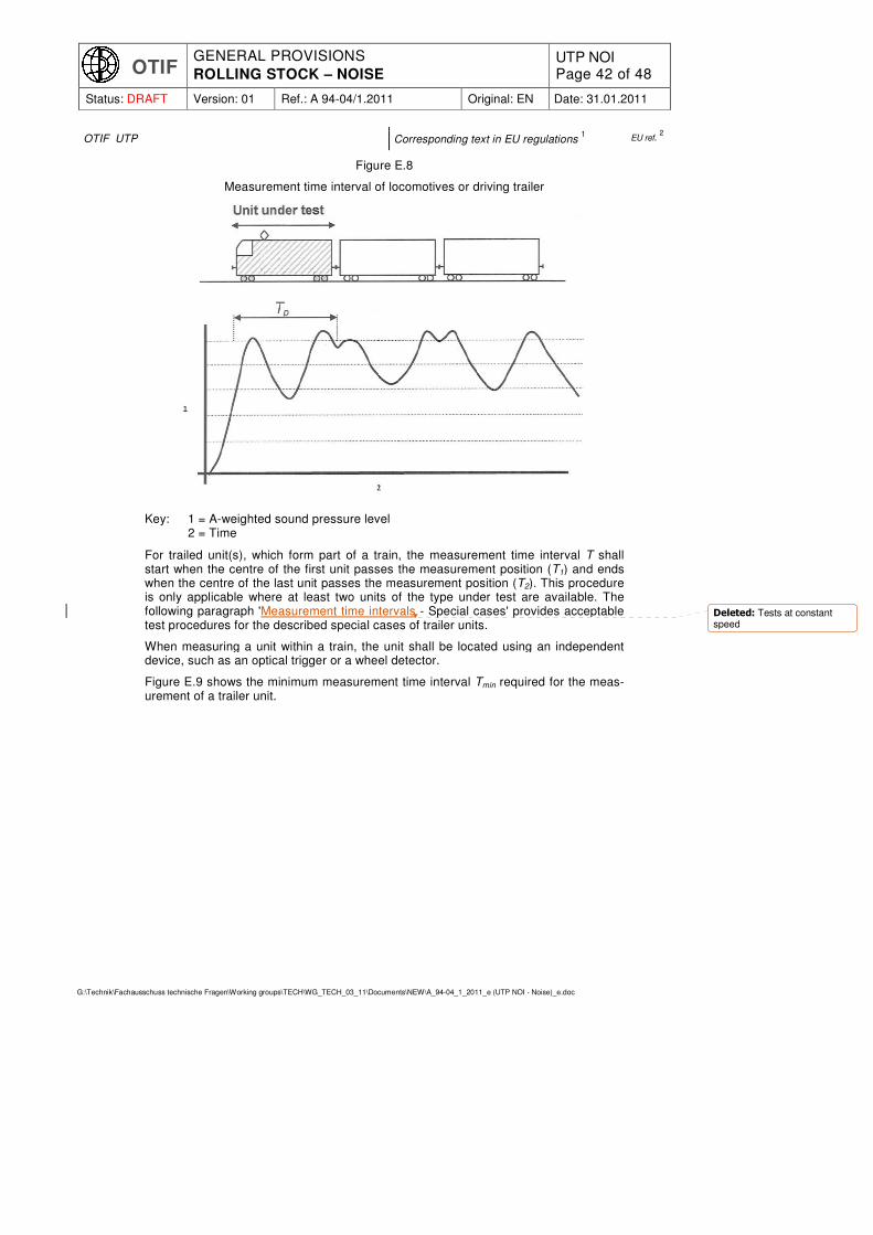
OTIF GENERAL PROVISIONS
ROLLING STOCK – NOISE UTP NOI Page 42 of 48
Status: DRAFT Version: 01 Ref.: A 94-04/1.2011 Original: EN Date: 31.01.2011
G:\Technik\Fachausschuss technische Fragen\Working groups\TECH\WG_TECH_03_11\Documents\NEW\A_94-04_1_2011_e (UTP NOI - Noise)_e.doc
OTIF UTP Corresponding text in EU regulations 1 EU ref.
2
Figure E.8
Measurement time interval of locomotives or driving trailer
Key: 1 = A-weighted sound pressure level 2 = Time
For trailed unit(s), which form part of a train, the measurement time interval T shall start when the centre of the first unit passes the measurement position (T1) and ends when the centre of the last unit passes the measurement position (T2). This procedure is only applicable where at least two units of the type under test are available. The following paragraph 'Measurement time intervals - Special cases' provides acceptable test procedures for the described special cases of trailer units.
When measuring a unit within a train, the unit shall be located using an independent device, such as an optical trigger or a wheel detector.
Figure E.9 shows the minimum measurement time interval Tmin required for the meas-urement of a trailer unit.
Deleted: Tests at constant speed

OTIF GENERAL PROVISIONS
ROLLING STOCK – NOISE UTP NOI Page 43 of 48
Status: DRAFT Version: 01 Ref.: A 94-04/1.2011 Original: EN Date: 31.01.2011
G:\Technik\Fachausschuss technische Fragen\Working groups\TECH\WG_TECH_03_11\Documents\NEW\A_94-04_1_2011_e (UTP NOI - Noise)_e.doc
OTIF UTP Corresponding text in EU regulations 1 EU ref.
2
Figure E.9
Example of selection of measurement time interval, T, for parts of a train
Key: 1 = A-weighted sound pressure level 2 = Time
E.6.2.3 Measurement time intervals – special cases
Only when the general assessment requirements as described in E.6.2.2 in this annex cannot be applied due to either the physical configuration of the unit under assess-ment is incompatible, or the unit is a one-off unit, it is permitted to use the special assessment method following the general rules as described under the heading 'Gen-eral rules' in this annex. The clauses as set out alter the 'general rules' define the application of the general rules to specific types of units.
E.6.2.3.1 General rules
� In any case adjacent vehicle(s) shall be acoustically neutral and therefore fulfil the conditions specified in section 'Train composition (adjacent vehicles)' of this annex.
� The measurement time interval chosen shall allow the assessment of the whole acoustic signature of the unit under test. Therefore the minimum measurement time interval Tmin shall correspond to the pass-by time (or a multiple of it) of this unit past the measurement position.
� The measurement time interval shall begin when the centre of the longest segment between two consecutive wheelsets passes the microphone and ends after the same position of the last unit under test passes the microphone.
E.6.2.3.2 Units with wheelsets located at or close to their centre
In some configurations, the wheelsets are located close to or directly at the centre of the unit under test. In such a case, the minimum measurement time interval Tmin shall not begin when the centre of the first unit under test but when the centre of the longest segment between two consecutive wheelsets of this unit passes the measurement position. lt ends after the equivalent location on the last unit passes the measurement position (see examples in Figure E.10 and Figure E.11).
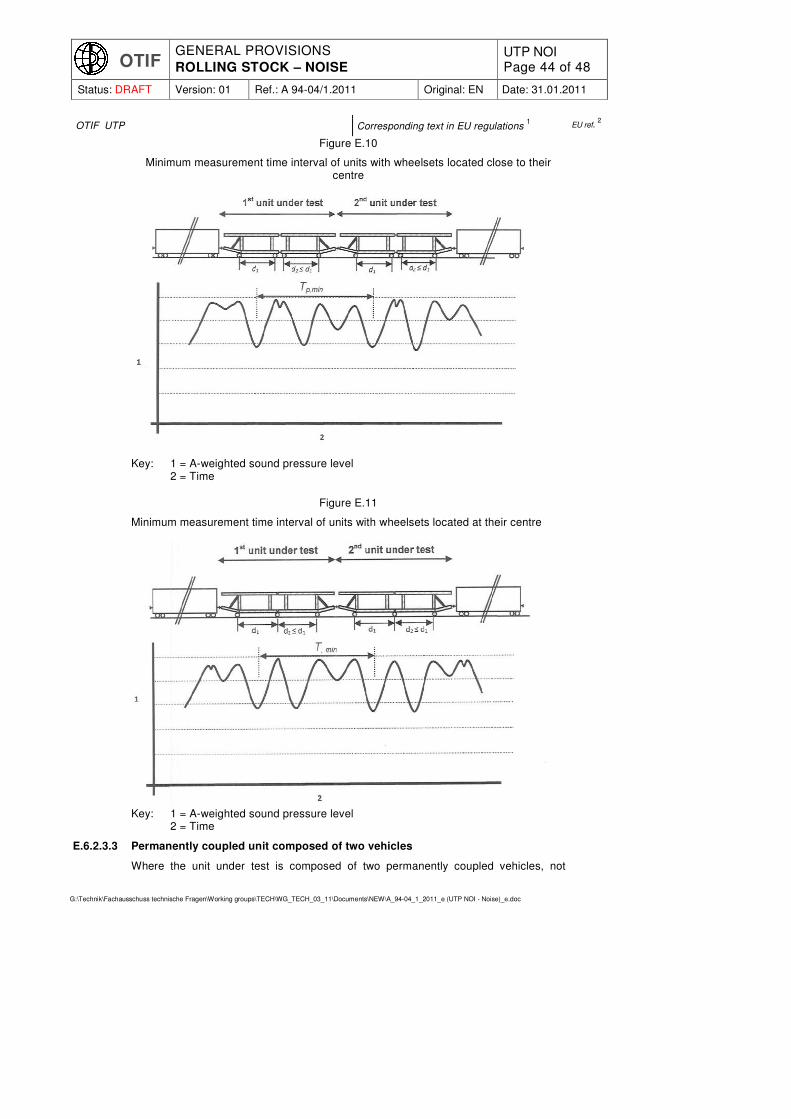
OTIF GENERAL PROVISIONS
ROLLING STOCK – NOISE UTP NOI Page 44 of 48
Status: DRAFT Version: 01 Ref.: A 94-04/1.2011 Original: EN Date: 31.01.2011
G:\Technik\Fachausschuss technische Fragen\Working groups\TECH\WG_TECH_03_11\Documents\NEW\A_94-04_1_2011_e (UTP NOI - Noise)_e.doc
OTIF UTP Corresponding text in EU regulations 1 EU ref.
2
Figure E.10
Minimum measurement time interval of units with wheelsets located close to their centre
Key: 1 = A-weighted sound pressure level 2 = Time
Figure E.11
Minimum measurement time interval of units with wheelsets located at their centre
Key: 1 = A-weighted sound pressure level 2 = Time
E.6.2.3.3 Permanently coupled unit composed of two vehicles
Where the unit under test is composed of two permanently coupled vehicles, not

OTIF GENERAL PROVISIONS
ROLLING STOCK – NOISE UTP NOI Page 45 of 48
Status: DRAFT Version: 01 Ref.: A 94-04/1.2011 Original: EN Date: 31.01.2011
G:\Technik\Fachausschuss technische Fragen\Working groups\TECH\WG_TECH_03_11\Documents\NEW\A_94-04_1_2011_e (UTP NOI - Noise)_e.doc
OTIF UTP Corresponding text in EU regulations 1 EU ref.
2
necessarily identical, it is permissible to measure only one unit, provided that both vehicles are point symmetric. In such a case, T1 corresponds to the passing of the centre of the first vehicle and T2 corresponds to the passing of the centre of the last vehicle of the unit.
NOTE: It is recommended to test such a unit at the end of the test train.
Figure E.12
Minimum measurement time interval for a unit composed of two different and perma-nently coupled vehicles
Key: 1 = A-weighted sound pressure level
2 = Time
E.6.2.3.4 Measurement of a single trailer unit
When a series consists of one unit, it is permissible to measure this single unit pro-vided that it is acoustically point symmetric.
This procedure does not apply to driving trailers.
The unit under test shall be positioned at the end of the train. The measurement time interval T shall begin when the centre of the unit passes the measurement position and ends when the noise level measured at the measurement position has decreased by at least 10 dB compared to the maximum noise level measured during pass-by of the unit (see Figure E.13).
The A-weighted equivalent pass-by noise level shall then be assessed according to
with
Tp = V
L 1
2× pass-by time of half of the unit in sec
L = length of unit in m V = train speed in m/sec
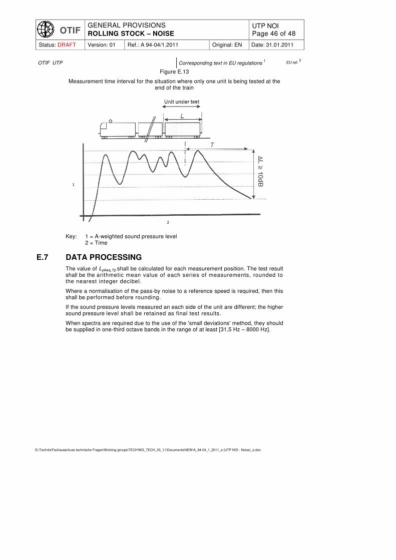
OTIF GENERAL PROVISIONS
ROLLING STOCK – NOISE UTP NOI Page 46 of 48
Status: DRAFT Version: 01 Ref.: A 94-04/1.2011 Original: EN Date: 31.01.2011
G:\Technik\Fachausschuss technische Fragen\Working groups\TECH\WG_TECH_03_11\Documents\NEW\A_94-04_1_2011_e (UTP NOI - Noise)_e.doc
OTIF UTP Corresponding text in EU regulations 1 EU ref.
2
Figure E.13
Measurement time interval for the situation where only one unit is being tested at the end of the train
Key: 1 = A-weighted sound pressure level 2 = Time
E.7 DATA PROCESSING
The value of LpAeq,Tp shall be calculated for each measurement position. The test result shall be the arithmetic mean value of each series of measurements, rounded to the nearest integer decibel.
Where a normalisation of the pass-by noise to a reference speed is required, then this shall be performed before rounding.
If the sound pressure levels measured an each side of the unit are different; the higher sound pressure level shall be retained as final test results.
When spectra are required due to the use of the 'small deviations' method, they should be supplied in one-third octave bands in the range of at least [31,5 Hz – 8000 Hz].

OTIF GENERAL PROVISIONS
ROLLING STOCK – NOISE UTP NOI Page 47 of 48
Status: DRAFT Version: 01 Ref.: A 94-04/1.2011 Original: EN Date: 31.01.2011
G:\Technik\Fachausschuss technische Fragen\Working groups\TECH\WG_TECH_03_11\Documents\NEW\A_94-04_1_2011_e (UTP NOI - Noise)_e.doc
OTIF UTP Corresponding text in EU regulations 1 EU ref.
2
ANNEX F: MEASUREMENT DETAILS FOR INTERIOR CAB NOISE MEASUREMENTS
The following conditions apply:
� the doors and windows must be closed,
� the hauled loads must be equal to at least two-thirds of the maximum permissible value.
For the measurements at maximum speed, the microphone shall be positioned at the level of the driver's ear (in the seated position), at the centre of a horizontal plane extending from the front window panes to the rear wall of the cab.
For the measurements of the horn's Impact, eight evenly spaced microphone positions around the position of the driver's head with a radius of 25 ±2,5 cm (in the seated position) shall be used, in a horizontal plane. The arithmetic mean of the eight values shall be assessed against the limit.

OTIF GENERAL PROVISIONS
ROLLING STOCK – NOISE UTP NOI Page 48 of 48
Status: DRAFT Version: 01 Ref.: A 94-04/1.2011 Original: EN Date: 31.01.2011
G:\Technik\Fachausschuss technische Fragen\Working groups\TECH\WG_TECH_03_11\Documents\NEW\A_94-04_1_2011_e (UTP NOI - Noise)_e.doc
OTIF UTP Corresponding text in EU regulations 1 EU ref.
2
ANNEX G: GENERAL INFORMATION AND DEFINITIONS RE-LATED TO NOISE TESTING
G.1 DEFINITIONS
Sound pressure p root mean square (RMS) value of a fluctuating pressure superimposed on the static atmospheric pressure measured over a certain time period, expressed in Pa
Sound pressure level Lp level given by the equation: Lp = 10 lg(p/po)
2 in dB
where La is the sound pressure level in dB; p is the RMS sound pressure in Pa; po is the reference sound pressure; po = 20 µPa
A-weighted sound pressure level LpA Sound pressure level obtained by using the frequency weighting A (see EN 61672-1 and EN 61672-2), given by the following equation: LpA = 10 lg(pA/po)
2 in dB
where LpA is the A-weighted sound pressure level in dB; pA is the RMS A-weighted sound pressure in Pa; po is the reference sound pressure; po = 20 µPa
AF-weighted sound pressure level history LpAF(t)
A-weighted sound pressure level as a function of time with time weighting F (fast)
AF-weighted maximum sound pressure level LpAFmax is the maximum value of the A-weighted sound pressure level determined during the measurement time interval T by using time weighting F (fast)
A-weighted equivalent continuous sound pressure level LpAeq,T is the A-weighted sound pressure level given by the following equation:
in dB where LpAeq,T is the A-weighted equivalent continuous sound pressure level in dB; T is the measurement time interval in sec; pA(t) is the A-weighted instantaneous sound pressure in Pa; po is the reference sound pressure; po = 20 µPa
G.2 MEASUREMENT TOLERANCES
All measurement distances mentioned in the standard shall be considered with a tolerance of ± 0,2 m if no requirement is specified.

Page 18: [1] Deleted KRA 12/7/2010 11:43:00 AM
The assessment is based on test procedures as set out in chapter 4 of this
UTP. TSI.
The following units are eligible for a simplified evaluation:
Different formations of multiple units,
Renewed or upgraded units in accordance with the provisions in clause 7.6 of this
UTP TSI
New units which are largely based on an existing design (same vehicle family).
For the units under assessment for simplified evaluation, the proof of conformity shall include a detailed description of the noise relevant changes compared to the reference type. From this description, a simplified evaluation (see sections 6.2.3.2 and 6.2.3.3) shall be performed to identify the differences in terms of expected noise emission, of the noise cases specified in section 4.2 between the reference unit and the unit under assessment.
lt is permitted to substitute noise testing by a simplified evaluation, if the type under assessment is based on a
UTP Noise Noise TSI
compliant existing type of unit (further referred to as reference type), under the condi-tion that the reference type has been tested in compliance with either:
chapter 4 of this
UTP TSI
and for which the pass-by noise results are marked 'comparable', or
In compliance with chapter 4 of the TSI CR 'rolling stock - noise', EU Commission Decision 2006/66/EC.
lt is permitted to use the simplified evaluation on a unit for each of the individual noise cases autonomously: stationary noise, starting noise, cab-noise and pass-by noise.