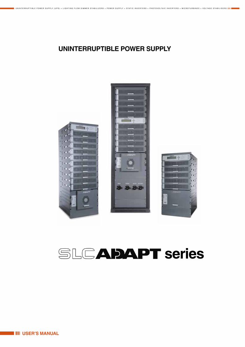
uninterruptible power supply - salicru
TRANSCRIPT
U N I N T E R R U P T I B L E P O W E R S U P P LY ( U P S ) + L I G H T I N G F L O W D I M M E R S TA B I L I Z E R S + P O W E R S U P P LY + S TAT I C I N V E R T E R S + P H O T O V O LTA I C I N V E R T E R S + M I C R O T U R B I N E S + V O LTA G E S TA B I L I S E R S
USER’S MANUAL
UNINTERRUPTIBLE POWER SUPPLY
series


3
GENERAL INDEX
SALICRU
General index
1. Introduction
1.1. Gratefulness letter
1.2. Using this manual1.2.1. Used conventions and symbols1.2.2. For more information and/or help1.2.3. Safety and first aid
2. Quality and standard guarantee
2.1. Management declaration
2.2. Standard
2.3. Environment
3. Safety Considerations
3.1. Do's
3.2. Don't's
4. Presentation
4.1. Features
4.2. Nomenclature
4.3. Ac input/output main terminals
4.4. System controller
4.5. UPS module (10 kVA / 8 kW)
4.6. Static Switch (ST/SW) module
4.7. Battery
5. Operating modes
5.1. Normal operation
5.2. Battery operation
5.3. Bypass operation
6. User interface
6.1. Control panel
6.2. UPS module panel
6.3. Static Switch panel (bypass)
6.4. Control screen6.4.1. Load-level bar graph
6.5. Navigation and operation keypad
6.6. Status indicators
6.7. Operation buttons
6.8. Network access indicator
6.9. UPS operation modes6.9.1. Normal operation6.9.2. Battery operation6.9.3. Bypass operation (automatic)6.9.4. Bypass operation (manual)6.9.5. Emergency power-off – EPO (manual)
7. System installation
7.1. Installing the Freestyle in a Cabinet
7.2. Cabling7.2.1. Neutral Line7.2.2. Installation Instructions for Standard 3-3 Configuration7.2.3. Installation Instructions for 3-1 Configuration7.2.4. Installation Instructions for 1-1 Configuration7.2.5. Connecting the Batteries within the Battery Cabinet
7.3. Ac and dc fuses
7.4. Special Terminal Connections7.4.1. Load on Bypass Alarm7.4.2. Battery Trip Coil7.4.3. Emergency Power-off
7.5. Inspections to be performed prior to installation
7.6. Installation procedure
7.7. First-time Startup7.7.1. Preparation7.7.2. Operation7.7.3. Continue first-time startup
7.8. Checks to be performed following initial startup
7.9. Connection diagram
7.10. Configuration7.10.1. Check Configured Modules7.10.2. Check Total Ampere-Hours7.10.3. Set Date and Time and Serial Number7.10.4. Define the IP Address of the UPS
7.11. Testing7.11.1. Blackout Test7.11.2. Cold Start7.11.3. Test under Load7.11.4. Check IP Communication with Controller (optional)7.11.5. Test Wing Option
8. UPS Routine Start-up
8.1. Start-up after Shutdown
8.2. UPS shutdown (switching to bypass)
8.3. UPS total shutdown (no ac output)
9. UPS control panel
9.1. Quick-Reference Summary of UPS Menu Functions
10. UPS Menu functions in detail
10.1. Main Menu
10.2. “System” Option
10.3. “UPS module” Option
10.4. “Self-test” Option
10.5. “History” (logs) Option
10.6. “Battery” Option
4
GENERAL INDEX
USER'S MANUAL
10.7. “Alarm” Option
10.8. “Setup – Alarm Set” Option10.8.1. Setting Ac Voltage Alarms10.8.2. Setting Battery Floating Voltage Alarm10.8.3. Setting Battery Over/Under Temperature Alarms10.8.4. Setting Battery Integration Alarm
10.9. “Setup – Module Conf.” Option10.9.1. Setting Number of Phases10.9.2. Setting Module/s Frequency10.9.3. Setting Module/s Voltage10.9.4. Update Voltage/Frequency/Phase10.9.5. Output Adjustment10.9.6. Setting Frequency Limits10.9.7. Calibrating DC Voltage10.9.8. Calibrating AC Voltage
10.10. “Setup – Battery” Option10.10.1. Setting Battery Test Voltage10.10.2. Setting Battery Test Voltage Alarm10.10.3. Setting Battery Current Limit10.10.4. Enable/Disable Battery Current Limit10.10.5. Setting Temperature Compensation10.10.6. Setting Disable Temperature Compensation10.10.7. Setting Absolute Maximum and Minimum Voltages10.10.8. Activating the Battery Test10.10.9. Setting the Automatic Battery Test Period10.10.10.Setting the Automatic Battery Test Top Time10.10.11.Setting the Nth Battery Capacity10.10.12.Activating ‘Auto’ Test10.10.13.Enabling/Disabling Options
10.11. "Setup – Charge, Time, Site, and Password" Options
10.11.1. Setting the Floating Charge10.11.2. Setting the Time10.11.3. Setting the Site Number10.11.4. Changing the Password
10.12. “Setup – Service” Option10.12.1. Setting UPSs10.12.2. Testing Dry Output Relays10.12.3. Configuring the UPS10.12.4. Enabling/Disabling Current Sharing10.12.5. Setting Power Factor Correction (PFC)10.12.6. Setting the SC2012
10.13. “Setup – “Silicon” Option
10.14. “Static Switch” option
10.15. System Controller Setup Verification10.15.1. Setup Verification Menu10.15.2. Connection Status of UPSs10.15.3. On/Off Status of UPSs10.15.4. Software and Communication Revision10.15.5. Network Parameters10.15.6. Dry Input and Output Relay Contact Status10.15.7. Alarms Status10.15.8. Setting the Menu Language10.15.9. System Parameter Settings
11. Web interface
11.1. Preliminaries to use of the Web interface
11.2. Main Screen
11.3. The Main Menu and its options11.3.1. “Analysis” main menu option11.3.2. “Modules” main menu option11.3.3. “STSW” (Static Switch) main menu option11.3.4. “Log” main menu option11.3.5. “Control” main menu option11.3.6.
"SMS” main menu option11.3.7. “Configuration” main menu option
12. Optional
12.1. SNMP Agent
12.2. Wing: Wireless Control12.2.1. Installing the Wing
13. Related Products
13.1. G4
13.2. G-Eye
14. Maintenance, warranty and service
14.1. Warranty conditions14.1.1. Covered product14.1.2. Warranty terms14.1.3. Out of the scope of supply
14.2. Available maintenance and service contracts
14.3. Technical service network
15. General Characteristics

5
GENERAL INDEX
SALICRU
List of figures
Fig. 1. 10 to 50 kVA configuration in 19” rackFig. 2. 60 to 100 kVA configuration in a 19” rackFig. 3. System - full complement Fig. 4. Control panelFig. 5. UPS module panelFig. 6. Static switch panelFig. 7. control screenFig. 8. Navigation and operation keypadFig. 9. Status indicatorsFig. 10. Network access indicatorFig. 11. control screen in normal operationFig. 12. Normal operation indicationFig. 13. Ac power failureFig. 14. Ac power failure indicationFig. 15. STSW warningFig. 16. STSW warning indicationFig. 17. Installing the Freestyle in a rack (a)Fig. 18. Installing the Freestyle in a rack (b)Fig. 19. Installing the Freestyle in a rack (c)Fig. 20. Installing the Freestyle in a rack (d)Fig. 21. Installing the Freestyle in a rack (e)Fig. 22. Installing the Freestyle in a rack (f)Fig. 23. Installing the Freestyle in a rack (g)Fig. 24. Installing the Freestyle in a rack (h)Fig. 25. Wrong way to connect with a four-pole
switchFig. 26. Acceptable connection for grounded generator and
4-pole switchFig. 27. Preferred generator (neutralized) and connection (3-
pole)Fig. 28. Terminals for 50 kVA modelFig. 29. Terminals for 100 kVA modelFig. 30. Schematic for 3-phase configurationFig. 31. Terminal connections for 3-1 configurationFig. 32. Block diagram: input and output configurationFig. 33. Schematic for 3-1 configurationFig. 34. Terminal connections for 1-1 configurationFig. 35. Block diagram: input and output configurationFig. 36. Schematic for 1-1 configurationFig. 37. Dc terminal locations on 50 kVA modelFig. 38. Dc terminal locations on 100 kVA modelsFig. 39. Photo of ac and dc fuses and terminals (50 kVA model)Fig. 40. Diagram of ac and dc fuses and terminals (50 kVA
model)Fig. 41. Fusibles AC y DC y terminales (mod. 100 kVA)Fig. 42. Diagram of ac and dc fuses and terminals (100 kVA
model)Fig. 43. Special purpose terminals in STSW trayFig. 44. Close-up of special purpose terminalsFig. 45. Start-up screen 1Fig. 46. Start-up screen 2Fig. 47. Start-up screen 3Fig. 48. Start-up screen 4Fig. 49. Default screen, with no load, for 3-phase outputFig. 50. Normal display, system under load (3-phase output)Fig. 51. Connection diagram (for completion by the customer)Fig. 52. Main MenuFig. 53. Password accessFig. 54. Setup menuFig. 55. Service menuFig. 56. Configure menuFig. 57. # of UPSs (Total)Fig. 58. # of UPSs (Redundancy)
Fig. 59. Battery statusFig. 60. Battery capacityFig. 61. Set battery capacityFig. 62. Date and timeFig. 63. Site numberFig. 64. Network menuFig. 65. IP AddressFig. 66. GatewayFig. 67. Network menuFig. 68. Network Connections screenFig. 69. Local Area Connection Properties screenFig. 70. Internet Protocol (TCP/IP) Properties screenFig. 71. Main Screen of built-in web serverFig. 72. Login screen of built-in web serverFig. 73. SMS screenFig. 74. Main screen after a power shutdownFig. 75. Main screen after a power shutdown indicationFig. 76. Main screen at power-upFig. 77. Normal operation indicationFig. 78. Main screen resultsFig. 79. Main screen – switching to bypassFig. 80. Bypass indicationFig. 81. Main screen – total shutdownFig. 82. UPS off indicationFig. 83. Control panelFig. 84. Main MenuFig. 85. System menuFig. 86. Battery menuFig. 87. Setup menuFig. 88. Static switch menuFig. 89. Alarm set sub-menuFig. 90. Module configuration sub-menuFig. 91. Battery MenuFig. 92. Service sub-menuFig. 93. Configure sub-sub-menuFig. 94. Silicon sub-menuFig. 95. Main MenuFig. 96. Main menu option 1 ("System")Fig. 97. System dc voltagesFig. 98. Output power factor 1Fig. 99. Input power factor 1Fig. 100. Overall phase voltages/currentsFig. 101. Elapsed timeFig. 102. Jumper settings WITHOUT remote panelFig. 103. Jumper settings WITH remote panelFig. 104. Internal controller voltagesFig. 105. Battery parametersFig. 106. Fuse statusFig. 107. Communication with inverter – transmitFig. 108. Communication with inverter – receiveFig. 109. Main Menu option 2 (“UPS Module”)Fig. 110. LCD Panel – select a UPSFig. 111. Module phase voltages/currentsFig. 112. Battery voltages & technician parametersFig. 113. Main Menu option 3 (“Self Test”)Fig. 114. Result screen from self-testFig. 115. Main Menu option 4 (“History”)Fig. 116. History logsFig. 117. History log scrollFig. 118. Main Menu option 5 (“Battery”)Fig. 119. Battery statusFig. 120. Battery equalizingFig. 121. Time leftFig. 122. Last testFig. 123. Battery current

6
GENERAL INDEX
USER'S MANUAL
Fig. 124. Battery capacityFig. 125. Battery current limitFig. 126. Main Menu option 6 (“Alarm”)Fig. 127. Alarms 01-12Fig. 128. Alarms 13-24Fig. 129. Alarms 25-32Fig. 130. Main Menu option 7 (“Setup – Alarm Set”)Fig. 131. Level 1 password access Fig. 132. Setup menuFig. 133. Alarm setup menuFig. 134. Ac alarms menuFig. 135. Set ac alarm voltage levelsFig. 136. Ac alarms menuFig. 137. Set ac voltage hysteresisFig. 138. Alarm set menuFig. 139. Battery floating charge alarm setup menu Fig. 140. Set BATENDFig. 141. Battery floating charge alarm setup menuFig. 142. Set BATLOWFig. 143. Battery floating charge alarm setup menuFig. 144. Set BAT-HIFig. 145. Alarm set menuFig. 146. Over/Under temperature menuFig. 147. Set battery maximum temperature alarmFig. 148. Over/Under temperature menuFig. 149. Set battery minimum temperature alarmFig. 150. Alarm set menuFig. 151. Set the integration factor alarmFig. 152. Main Menu option 7 (“Setup – Module Conf.”)Fig. 153. Level 1 password accessFig. 154. Setup menuFig. 155. Module Config. setup menuFig. 156. Module Config. setup menuFig. 157. Setting the Module/s frequencyFig. 158. Module Config. setup menuFig. 159. Setting the Module/s voltageFig. 160. Module Config. setup menuFig. 161. Updating the Module/s voltage/frequency/phaseFig. 162. Module Config. setup menuFig. 163. Select a phase to adjustFig. 164. Select a module to adjustFig. 165. : Select a value to adjustFig. 166. Module Config. setup menuFig. 167. Select the frequency limitsFig. 168. Module Config. setup menuFig. 169. Calibrate Positive or Negative VoltageFig. 170. Enter measured valueFig. 171. Module Config. setup menuFig. 172. : Calibrate INPUT or OUTPUT VoltageFig. 173. Enter measured valueFig. 174. Main Menu option 7 (“Setup – Battery”)Fig. 175. Level 1 password accessFig. 176. Setup menuFig. 177. Battery setup menuFig. 178. Set battery test voltageFig. 179. Battery setup menuFig. 180. : Set battery test voltage alarmFig. 181. Battery setup menuFig. 182. Current Limit setup menuFig. 183. Current limit indication for (each) batteryFig. 184. Set Current limit for (each) batteryFig. 185. Battery setup menuFig. 186. Current Limit setup menuFig. 187. Enable/Disable current limitFig. 188. Battery setup menu
Fig. 189. Temperature compensation setup menuFig. 190. Set temperature compensationFig. 191. Battery setup menuFig. 192. Enable/Disable temperature compensationFig. 193. Select Set ABSOLUTE Max & Min VoltagesFig. 194. Select Set absolute minimum output voltageFig. 195. Set absolute minimum output voltage when
compensatingFig. 196. Select Set absolute maximum output voltageFig. 197. Set absolute maximum output voltage when
compensatingFig. 198. Battery setup menuFig. 199. Select Activate Battery Test…Fig. 200. Activate battery testFig. 201. Battery setup menuFig. 202. Select Set auto battery test periodFig. 203. Set battery test periodFig. 204. Battery setup menuFig. 205. Select Set auto battery test top timeFig. 206. Set battery test top timeFig. 207. Battery setup menuFig. 208. Select Set capacity of battery #1Fig. 209. Set battery capacityFig. 210. Battery setup menuFig. 211. Activated ‘Auto’ testFig. 212. Battery setup menuFig. 213. Enable/Disable shutdown by long AC failureFig. 214. Main Menu option 7 (“Setup – Charge, Time, Site, &
Password”)Fig. 215. Level 1 password accessFig. 216. Setup menuFig. 217. Charge setup menuFig. 218. Set floating chargeFig. 219. Setup menuFig. 220. Set date and timeFig. 221. Setup menuFig. 222. Set site numberFig. 223. Setup menuFig. 224. Change passwordFig. 225. Main Menu option 7 (“Setup – Service”) 1/2Fig. 226. Main Menu option 7 (“Setup – Service”) 2/2Fig. 227. Level 1 password accessFig. 228. Setup menuFig. 229. Service menuFig. 230. Set UPSsFig. 231. Service menuFig. 232. Set UPSsFig. 233. Service menuFig. 234. Service > Configure menuFig. 235. Set number of redundant UPSsFig. 236. Service > Configure menuFig. 237. Set total number of UPSsFig. 238. Service > Configure menuFig. 239. Set total number of batteriesFig. 240. Service > Configure menuFig. 241. Static Switch setup menuFig. 242. Set the maskFig. 243. Static Switch setup menuFig. 244. Service > Configure menuFig. 245. Dry relay menuFig. 246. Set dry contact N alarm associationsFig. 247. Enable / disable alarmsFig. 248. Service > Configure menuFig. 249. DC-I menuFig. 250. Remove current offsets

7
GENERAL INDEX
SALICRU
Fig. 251. DC-I menuFig. 252. Calibrating DC currentFig. 253. Entering actual currentFig. 254. Service > Configure menuFig. 255. Setting standalone or parallel operationFig. 256. Service > Configure menuFig. 257. Enabling/disabling remote commandsFig. 258. Service menuFig. 259. Enabling/disabling current sharingFig. 260. Service menuFig. 261. Enabling/disabling power factor correctionFig. 262. Service menuFig. 263. SC2012 menuFig. 264. SC2012 menuFig. 265. SC2012 menuFig. 266. Network menuFig. 267. Setting an IP addressFig. 268. Network menuFig. 269. Setting the gatewayFig. 270. Network menuFig. 271. Setting the maskFig. 272. Network menuFig. 273. Network menuFig. 274. Setting the SNMP NO COMM factorFig. 275. SC2012 menuFig. 276. Main Menu option 7 (“Setup – Static Switch”)Fig. 277. Level 1 password accessFig. 278. Setup menuFig. 279. Silicon menuFig. 280. Silicon menuFig. 281. Silicon defaultsFig. 282. Confirmation screenFig. 283. Silicon menuFig. 284. Static switch optionFig. 285. Static switch voltage and frequencyFig. 286. Static switch messaging statusFig. 287. Setup verification screensFig. 288. Setup verification menuFig. 289. Connection status of UPSsFig. 290. On/Off status of UPSsFig. 291. Software and communication revisionFig. 292. Network parametersFig. 293. Dry input and output relay contact statusFig. 294. Alarms statusFig. 295. Set menu languageFig. 296. Select GeneralFig. 297. General (Screen 1)Fig. 298. General (Screen 2)Fig. 299. General (Screen 3)Fig. 300. General (Screen 4)Fig. 301. controller rear panelFig. 302. Main Screen of the Web interfaceFig. 303. Analysis of system input and output voltages and powerFig. 304. Modules measurements and status displayFig. 305. Static Switch data and status displayFig. 306. Listing the log entriesFig. 307. The "Control" main menu option screenFig. 308. “SMS” screenFig. 309. Configuration menuFig. 310. Configuring network communication parametersFig. 311. Setting the UPS internal date and timeFig. 312. Changing username and password of the Web interfaceFig. 313. Define SNMP permissionsFig. 314. Defining SNMP trap targetsFig. 315. Define computers for auto-shutdown
Fig. 316. Defining email notification targetsFig. 317. Defining SMS recipientsFig. 318. PSM-AC lets you monitor and control
your UPSFig. 319. A Wing unit connected to the Fig. 320. Connections between the controller and
the WingFig. 321. Home screen of the web interfaceFig. 322. The SMS screen on the web interfaceFig. 323. GMaCi G4Fig. 324. G-Eye
List of tables
Table 1. Status indicatorsTable 2. Operation buttonsTable 3. Network access indicationTable 4. Cable and circuit breaker size recommendationsTable 5. Required over-current protection (10 – 50 kVA)Table 6. Required over-current protectionTable 7. Pre-installation inspections Table 8. Procedimiento de instalaciónTable 9. Checklist following initial startupTable 10. Main Menu OptionsTable 11. Log MessagesTable 12. Interpreting the Static Switch transfer code (LOADBP)Table 13. Main Screen featuresTable 14. Main Menu optionsTable 15. Data items on the event log screenTable 16. Alarm message text in Web interface log display. (Use
the alarm number in this table to reference Table 11 for a fuller explanation of the alarm condition).
Table 17. Commands available on the “Control” screenTable 18. Defining computers for auto-shutdownTable 19. Fields in the email notifications screenTable 20. Fields in the SMS notification target definition screenTable 21. List of SMS commandsTable 22. SpecificationsTable 23. Control system specifications

8
INTRODUCTION
USER'S MANUAL
1. Introduction
1.1. Gratefulness letter
We would like to thank you in advance for the trust you have placed in us by purchasing this product. Read this instruc-tion manual carefully before starting up the equipment and keep it for any possible future consult that can arise.
We remain at you entire disposal for any further information or any query you should wish to make.
Yours sincerely.
SALICRU
� The equipment here described can cause impor-tant physical damages due to wrong handling. This is why, the installation, maintenance and/or fixing of the here described equipment must be done by our staff or specifically authorised.
� According to our policy of constant evolution, we re-serve the right to modify the specifications in part or in whole without forewarning.
� All reproduction or third party concession of this manual is prohibited without the previous written authorization of our firm.
1.2. Using this manual
The target of this manual is to give explanations and pro-cedures for the installation and operating of the equipment. This manual has to be read carefully before installing and operating it. Keep this manual for future consults.
This equipment has to be installed by qualified staff and, the simple help of this manual, it can usable by personnel without specific training.
1.2.1. Used conventions and symbols
«Warning» symbol. Carefully read the indicated paragraph and take the stated prevention meas-
ures.
«Danger of electrical discharge» symbol. Pay special attention to it, both in the indication on the
equipment and in the paragraph referred to this user’s manual.
i «Main protective earthing terminal» symbol. Con-nect the earth cable coming from the installation to
this terminal.
«Earth bonding terminal» symbol. Connect the earth cable from the loads or battery cabinet to this terminal.
i «Notes of information» symbol. Additional topics that complement the basic procedures.
Preservation of the environment: The presence of this symbol in the product or in their associated doc-umentation states that, when its useful life is expired,
it will not be disposed together with the domestic residuals. In order to avoid possible damages to the environment, separate this product from other residuals and recycle it suitably. The users can contact with their provider or with the pertinent local authorities to be informed on how and where they can take the product to be recycled and/or dis-posed correctly.
1.2.2. For more information and/or helpFor more information and/or help of the version of your spe-cific unit, request it to our Service and Technical Support (S.T.S.).
1.2.3. Safety and first aidTogether with the equipment and this «User and installa-tion manual», it is provided the information regarding to «Safety instructions» (See document EK266*08). Before proceeding to the installation or commissioning, check that both information are available; otherwise request them. It is obligatory the compliance of the «Safety instructions», being the user the legal responsible regarding to its obser-vance. Once read, keep them for future consults that can arise.

9
QUALITY AND STANDARD GUARANTEE
SALICRU
2. Quality and standard guarantee
2.1. Management declaration
Our target is the client’s satisfaction, therefore this Manage-ment has decided to establish a Quality and Environmental policy, by means of installation a Quality and Environmental Management System that becomes us capable to comply the requirements demanded by the standard ISO 9001 and ISO 14001 and by our Clients and concerned parts too.
Likewise, the enterprise Management is committed with the development and improvement of the Quality and Environ-mental Management System, through:
• The communication to all the company about the im-portance of satisfaction both in the client’s requirements and in the legal and regulations
• The Quality and Environmental Policy diffusion and the fixation of the Quality and Environment targets.
• To carry out revisions by the Management.
• To provide the needed resources.
2.2. Standard
The product is designed, manufactured and commercialized in accordance with the standard EN ISO 9001 of Quality Assurance. The marking shows the conformity to the EEC Directive (quoted between brackets) by means of the application of the following standards:
• 2006/95/EC of Safety of Low Voltage
• 2004/108/EC of Electromagnetic Compatibility (EMC).
• in accordance with the specifications of the harmonized standards. Standards of reference:
• EN 60950-1: Equipment Information Technology. Secu-rity. Part 1: General requirements.
• IEC/EN 62040-2: Uninterruptible power supplies (UPS). Part 2: Requirements for Electromagnetic Compatibility (EMC).
• IEC/EN 62040-3: Uninterruptible power supplies (UPS). Part 3: Methods of operation and specification of test requirements.
i The declaration of conformity CE of the product is at the disposal of the client previous express request to our head offices.
2.3. Environment
Equipment recycling at the end of its useful life:Our company commits to use the services of authorised societies and according to the regulations, in order to treat the recovered product at the end of its useful life (contact your distributor).
Packing: To recycle the packing, follow the legal regulations in force.
Batteries:The batteries mean a serious danger for health and environment. The disposal of them must be done in accordance with the standards in force.
10
SAFETY CONSIDERATIONS
USER'S MANUAL
3. Safety Considerations
The UPS system is designed for industrial applications and harsh environments.
Nevertheless, the UPS system is a sophis-ticated power system and should be handled with appro-priate care, following these guidelines.
3.1. Do's
• Read this manual carefully before starting installation and operation of the UPS.
• Review the safety precautions described below to avoid injury to users or damaging equipment.
• All power connections must be completed by a li-censed electrician who is experienced in wiring this type of equipment, and who is knowledgeable about all federal, state, and local electrical codes and regu-lations. Improper wiring may cause damage to the equipment or injury to personnel.
• Pay attention to the warning signs, labels and marks on the unit. A warning sign signals the presence of a pos-sibly serious, life-threatening condition.
• Keep the surroundings clean, uncluttered and free from excess moisture.
• Allow only qualified technicians to service the UPS. There are no user-serviceable components. Do not try to repair it yourself!
• Use the UPS only for its intended purpose
WARNING - RISK OF LETHAL ELECTRIC SHOCK:
The battery drawer contains a series of 12-Volt batteries that provide high voltage and
energy in the UPS body even when the UPS is not connected to the AC input.
Appropriate precautions should be taken during installation, inspection and servicing.
3.2. Don't's
• Do not open the cover of the UPS or the battery cabi-nets under any circumstances. All UPS panels and doors should be closed.
• Do not insert any objects through the ventilation holes.
• Do not put objects on the UPS.
• Do not move the UPS while it is operating.
• Do not use the UPS outdoors.
• Do not turn the UPS upside down during transportation.
• Do not connect or disconnect the cable to the battery cabinet before the battery circuit breaker is turned OFF.
• Do not turn ON the battery circuit breaker when the bat-tery cabinet is disconnected from the UPS.
• Do not install next to any gas or electrical heaters. A restricted location is recommended in order to prevent access by unauthorized personnel
WARNING: RISK OF SEVERE DAMAGE TO THE UPS!!!
THIS SYSTEM USES THE NEUTRAL LINE FOR OPERATION. THEREFORE, IT IS STRICTLY
FORBIDDEN TO CONNECT THIS SYSTEM TO THE AC POWER SOURCE WITHOUT A NEUTRAL (NULL) CONDUCTOR!!
FAILURE TO USE A NEUTRAL CONDUCTOR MAY CAUSE PERMANENT DAMAGE TO THE
SYSTEM.
11
PRESENTATION
SALICRU
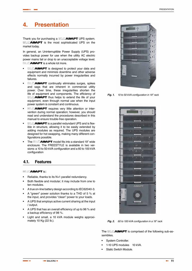
4. Presentation
Thank you for purchasing a UPS system. is the most sophisticated UPS on the
market today.
In general, an Uninterruptible Power Supply (UPS) pro-vides backup power for use when the utility AC electric power mains fail or drop to an unacceptable voltage level.
is a whole lot more.
• is designed to protect your data and equipment and minimize downtime and other adverse effects normally incurred by power irregularities and failures.
• continually eliminates surges, spikes and sags that are inherent in commercial utility power. Over time, these irregularities shorten the life of equipment and components. The efficiency of
thus helps to extend the life of your equipment, even through normal use when the input power system is constant and continuous.
• requires very little attention or inter-vention during normal operation; however, you should read and understand the procedures described in this manual to ensure trouble-free operation.
• is a parallel redundant UPS and is flex-ible in structure, allowing it to be easily extended by adding modules as required. The UPS modules are designed for hot swapping, making many different con-figurations possible.
• The model fits into a standard 19” wide enclosure. The FREESTYLE is available in two ver-sions: a 10 to 50-kVA configuration and a 60 to 100 kVA configuration
4.1. Features
is::
• Reliable, thanks to its N+1 parallel redundancy.
• Both flexible and modular; it may include from one to ten modules.
• A true on-line battery design according to IEC62040-3.
• A "green" power solution thanks to a THD of 5 % at the input, and provides “clean” power to your loads.
• A UPS that employs active current sharing at the input / output.
• A UPS that has an overall efficiency of up to 96 % and a backup efficiency of 98 %.
• Light and small, a 10 kVA module weighs approxi-mately 10 Kg (22 lb.).
Fig. 1. 10 to 50 kVA configuration in 19” rack
Fig. 2. 60 to 100 kVA configuration in a 19” rack
The is comprised of the following sub-as-semblies.
• System Controller.
• 1-10 UPS modules × 10 kVA.
• Static Switch Module.

12
PRESENTATION
Control del sistema
Interruptor estático (Bypass)
Módulos del SAI, de 10kVA cada uno
USER'S MANUAL
Fig. 3. System - full complement
4.2. Nomenclature
ADAPT UPS module
SLC-10-ADAPT L 60Hz
60 Hz Frequency fitted in the module. To omit for 50 Hz.
L Exact module to single-phase. To omit for three-phase.
ADAPT UPS series.
10 UPS module kVA power.
Subrack for ADAPT UPS
S-5ADAPT
ADAPT UPS series.
5 Subrack for 50 kVA.
10 Subrack for 100 kVA. S Subrack
Bypass for ADAPT UPS
STS-5ADAPT
ADAPT UPS series.
5 Static Bypass for 50 kVA subrack.
10 Static Bypass for 100 kVA subrack. STS Static Bypass
13
PRESENTATION
SALICRU
Control for ADAPT UPS
CONTROL-ADAPT
ADAPT UPS series
CONTROL Control for ADAPT series subracks
4.3. Ac input/output main terminals
The main input and output terminals are located at the lower rear of the unit. The terminals are used to connect the ac input and bypass inputs, the battery, and the ac output.See Fig. 40 (for 50 kVA units) or Fig. 42 (for 100 kVA units).
4.4. System controller
The system controller has multiple pur-poses:
• To allow the user to manage and control the UPS.
• To monitor the parameters of all sections of the via the control panel.
• To collect and summarize data from all sections of the UPS.
• To communicate with external computers for data transfer and operation
The can operate without the system controller but with reduced functionality.
4.5. UPS module (10 kVA / 8 kW)
The UPS module is the core of the , which consists of from one to ten identical modules in parallel de-pending on capacity requirements.
Each module includes a 3-phase charger with PFC and a 3-phase PWM inverter connected to batteries by a classic dc link. Each module is plug-in and weighs a mere 10 kg (22 lb.), approximately.
4.6. Static Switch (ST/SW) module
The centralized hybrid Static Switch enables an automatic transfer of the load from the output of the inverters to an al-ternate source whenever the inverter can no longer supply power to the load. The static switch can transfer high cur-rents at high speed.
4.7. Battery
The battery bank is used as a backup in the event that the utility ac input fails.
For systems from 10 kVA through 40 kVA, the batteries may be housed internally, however for systems from 50 kVA through 100 kVA, or for sites where a long backup duration is required, the batteries are housed in an external cabinet next to the cabinet.
Batteries are charged by the rectifier that powers both the inverter and the battery charger.
Free air circulation around the batteries is ex-tremely important for proper battery safety. If
the is installed in a cabinet, the cabinet must have sufficient ventilation openings to permit free air circulation around the batteries.This means that solid glass or acrylic-type door panels are not suitable for a cabinet housing the
, neither for the front cabinet door nor for the rear door.

14
OPERATING MODES
USER'S MANUAL
5. Operating modes
The UPS functions to supply ac electrical power to your load.
While using the , three modes of operation are possible:
• Normal operation
• Battery operation
• Bypass operation
All three operation modes are encountered during normal UPS use to constantly provide regulated voltage to the load.
In the normal operation mode, the UPS provides total power protection for the load.
In the battery operation mode, the load power is supplied by the battery.
In the bypass mode, power is transferred directly from the ac input to the load, bypassing the inverter. In this mode, there is no protection but it is useful for short-term opera-tion. When power is restored, the UPS returns to normal operation.
In addition to the three operation modes that are set au-tomatically by the UPS, two additional modes can only be invoked via manual intervention: by either the user or a technician:
• Maintenance bypass.
• Emergency Power Off (EPO).
• Details of each mode of operation are described in the sections below.
5.1. Normal operation
The UPS is almost always in normal operation mode. The load receives its power from the inverters that supply sta-bilized voltage, protected from spikes and irregularities in the ac input.
The ac input system feeds the charger that supplies dc power to the inverter, while concurrently charging the bat-teries.
5.2. Battery operation
During battery operation, the load continues to receive power from the inverters, but the dc input to the inverter is taken from the batteries, instead of from the rectifier.
The batteries are galvanically connected by dc link to the in-verter and the charger. The dc inherently remains constant when the ac input supply drops out, without any switching devices.
The duration of the battery operation is determined by the load demand and the battery capacity.
5.3. Bypass operation
During bypass operation, the load receives power directly from the ac input via the static switch.
Whenever the inverters cannot provide power to the load, either due to an overload or a short-circuit in the load, transfer to the ac input is automatic. As soon as the problem is corrected, the load is transferred back to the inverter.

15
USER INTERFACE
SALICRU
6. User interface
This section describes the buttons and indicators used to operate the .
6.1. Control panel
The Control Panel, located on the front of the controller, provides the user with an interface to the system. It includes an LCD display, a keypad, buttons and indicators for monitoring and control-ling the UPS configuration and functions. The control panel is aimed at both the end-user as well as the service engi-neer. All of the parameters can be viewed on the control panel.
Use of the Control Panel is described in detail in "UPS control panel".
Fig. 4. Control panel
6.2. UPS module panel
The UPS module panel, located on the front of each UPS module, provides the user with the status of that module.
Fig. 5. UPS module panel
Network access indicator
Navigation and Operation keypad
Status indicators
Operation buttons
LCD Panel
6.3. Static Switch panel (bypass)
The static switch panel, located on the front of static switch module, provides the user with the status of the static switch module. All the functions and indications are available on the Control Panel.
Fig. 6. Static switch panel

16
USER INTERFACE
USER'S MANUAL
6.4. Control screen
The control screen is illustrated below. It is part of the control panel described on "Control panel". How to read and understand the control screen is described in detail in "UPS control panel".
The control screen provides menus and displays all aspects of the systems input, output and static switch as well as operational details. The Fig. 7 below shows the 3-phase display.
LOAD LEVEL ---11:20:25---L1: _____ 015A, 230V BATTERY: 864VL2: ______ 012A, 230V UPS OK (ON)L3: _______ 011A, 230V STSW OK (INV)
Load level bar graph
Outputcurrent
Outputvoltage
Currenttime
Batteryvoltage
Statusindications
Load level bar graph
Output current
Output voltage
Battery voltage
Status
Current time
Fig. 7. control screen
This is how the control screen appears while the UPS is running normally.
6.4.1. Load-level bar graphThe load-level bar graph on the default screen display il-lustrates the approximate load on each output phase of the UPS, as a percent of the maximum available output for each phase.
The load on each phase is represented by a series of from 1 to 10 dots. Each dot represents about 10 % of the maximum available output per phase.
The dots can be either filled in (black) or clear (white). The number of black dots represents kW, and the number of black and white dots together represents kVA (apparent power).
For example, in Fig. 7, the load on Line 2 is 30 % (3 black dots) of the maximum in terms of kW, and 40 % (3 black dots plus 1 white dot) of the maximum in terms of kVA.
To compute the approximate value in kW or kVA of each dot:
1. Compute the maximum load per phase =
10 kVA [or 8kW] x (total #modules - redund. #modules)
3 phases
Dividing the maximum load per phase by 10 gives you the value of 1 dot.
Example: Assume a system with 10 modules, 2 of which are redundant.
10 kVA / 3 x (10-2) = 3.33 x 8 = maximum load per phase = 26.67 kVA.
Thus, 26.67 / 10 = 2.67 kVA is the approximate value of each dot.
6.5. Navigation and operation keypad
The navigation and operation keypad works in conjunction with the control screen. It allows you to navigate through the available menus using the direction arrow buttons and the Enter and Escape buttons to select or quit, respectively.
Fig. 8. Navigation and operation keypad
6.6. Status indicators
The status indicators show precisely what is running and how the UPS is providing power to the load.
The diagram below shows the power source and destina-tion routes in use for each of the 3 automated operation modes.
Normal operation
Bypass operation
Battery operation
Fig. 9. Status indicators
Ac Line Green – Shows that the ac input is present and within range
Alarm Red – Flashes to indicate general alarm condition
Battery Green – Shows that the battery is in discharge mode
Bypass Green – Shows that the load is supplied from the ac input
Inverter Green - Shows that the inverter is supplying power to the load
Bat. Test Blinking Red – Shows that a battery test is in progressSteady Red – Battery test failure
UPS On Green – Indicates that the UPS is running
Load Green – Indicates that ac voltage is available at the output
Table 1. Status indicators
17
USER INTERFACE
SALICRU
6.7. Operation buttons
The operation buttons illustrated below are “soft” switches.
• On/Off resets the entire UPS.
• Alarm silence shuts the alarm sounder.
• Inv/Byp allows the maintenance engineer to manually change the operation mode.
UPS ON/OFF switch
Alarm silence
Inverter/Bypass manual switch over
Table 2. Operation buttons
6.8. Network access indicator
The network access indicator shows whether the network connection is available and whether it is active.
Fig. 10. Network access indicator
Link Red – Indicates the presence of a network connection link
Act Green – Indicates that the network is active
Table 3. Network access indication
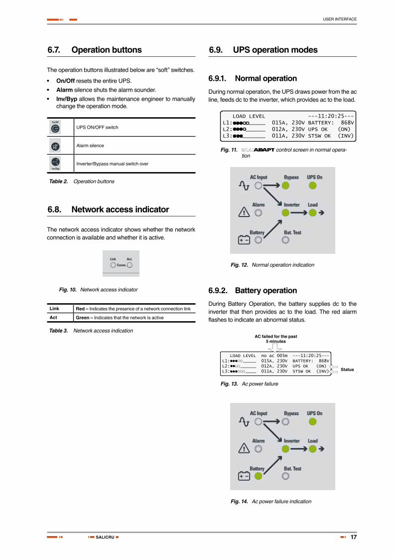
6.9. UPS operation modes
6.9.1. Normal operationDuring normal operation, the UPS draws power from the ac line, feeds dc to the inverter, which provides ac to the load.
LOAD LEVEL ---11:20:25---L1: _____ 015A, 230V BATTERY: 868VL2: ______ 012A, 230V UPS OK (ON)L3: _______ 011A, 230V STSW OK (INV)
Fig. 11. control screen in normal opera-tion
Fig. 12. Normal operation indication
6.9.2. Battery operationDuring Battery Operation, the battery supplies dc to the inverter that then provides ac to the load. The red alarm flashes to indicate an abnormal status.
LOAD LEVEL no ac 005m ---11:20:25---L1: _____ 015A, 230V BATTERY: 868VL2: ______ 012A, 230V UPS OK (ON)L3: ____ 011A, 230V STSW OK (INV)
AC failed for the past 5 minutes
Statusindications
AC failed for the past 5 minutes
Status
Fig. 13. Ac power failure
Fig. 14. Ac power failure indication

18
USER INTERFACE
USER'S MANUAL
6.9.3. Bypass operation (automatic)During Bypass operation, the ac feeds the load via the by-pass static switch. The red alarm flashes to indicate an ab-normal status
LOAD LEVEL ---12:01:11---L1: _____ 015A, 230V BATTERY: 868VL2: _____ 012A, 230V UPS OK (ON)L3: ______ 011A, 230V STSW OK (BYP)
Statusindications
Status
Fig. 15. STSW warning
Fig. 16. STSW warning indication
6.9.4. Bypass operation (manual)If the is manually switched to bypass oper-ation by pressing the Inv/Byp button, the load is transferred to the mains ac input line. Transfer back to normal opera-tion must be performed manually. The red alarm indicator flashes to indicate an abnormal status.
6.9.5. Emergency power-off – EPO (manual)
An external Emergency Power Off (EPO) switch can be in-stalled by the customer. The EPO switch cuts power to the load in emergency situations. Once switched OFF by the EPO, the must be restarted manually.
The EPO switch must be an N.O.-type, rated for at least 24 Vdc, 1 A.

19
SYSTEM INSTALLATION
SALICRU
7. System installation
7.1. Installing the Freestyle in a Cabinet
The Freestyle model must be installed in a 19-inch cabinet. This section explains how to do so.
To install the Freestyle UPS in a 19-inch cabinet:1. Remove the controller and the UPS
modules from the chassis. This is ac-complished by unscrewing the two screws – one on each side – that hold each module in place (see and ).
2. Remove the cage nuts that were used to hold each module in place, two for each module, and one on each side of the chassis.
3. Remove the screws and the cage nuts that hold the Static Switch module in place, but DO NOT remove the Static Switch module itself.
Module anchoring
screws
Module anchoring
screws
Cage nuts
Static switch
Fig. 17. Installing the Freestyle in a rack (a)
Module anchoring
screws
Cage nuts
Fig. 18. Installing the Freestyle in a rack (b)
4. Install cage nuts on the right and left mounting flange of the 19-inch cabinet. Cage nuts must be installed for the controller and for each UPS unit, and cage nuts must be installed to anchor the chassis to the 19-inch cabinet. Generally speaking, the cage nuts should be installed in alternating fashion – one for anchoring the chassis, one for anchoring the UPS module, one for the chassis, one for the module, and so on. See , and .
Cage nuts to anchor
modules
19 in. cabinet
Cage nuts to anchor
modules
Cage nuts to anchor
chassis
This column of cage nuts is actually not
visible from this angle, being on the inside of
the cabinet wall
Cage nuts to anchor
chassis
Fig. 19. Installing the Freestyle in a rack (c)
Left front side of 19-
inch cabinet
Mounting flange
Cage nuts to anchor
chassis
Cage nuts to anchor
chassis
Cage nuts to anchor
modules
Cage nuts to anchor
modules
Fig. 20. Installing the Freestyle in a rack (d)

20
SYSTEM INSTALLATION
USER'S MANUAL
Cage nuts to anchor
chassis
Cage nuts to anchor
chassis
Cage nuts to anchor
modules
Cage nuts to anchor
modules
Left front side of 19-inch
cabinet
Mounting flange
Fig. 21. Installing the Freestyle in a rack (e)
5. Lift the chassis into the 19-inch cab-inet. This is a two-person job, because the chassis is heavy and awkward to move.
6. Secure the chassis to the 19-inch cab-inet by inserting M6 screws through the chassis and the mounting flange of the 19-inch cabinet, into the cage nuts. See below (Remember that you also have to leave cage nuts in the 19-inch cabinet free for the power module screws.).
M6 screws to anchor
chassis
M6 screws to anchor
chassis
Cage nuts to anchor
chassis
This column of cage nuts is actually not visible from this angle, being on the inside of
the cabinet wall
19 in. cabinet
Fig. 22. Installing the Freestyle in a rack (f)
7. Slide the controller module and the power modules into place in the chassis and secure them in place by screwing their screws through the Power+ chassis and the 19-inch cabinet into the cage nuts (See and ).
Fig. 23. Installing the Freestyle in a rack (g)
Controller
UPS mod-ules
Cage nuts to anchor
modules19 in.
cabinet
Fig. 24. Installing the Freestyle in a rack (h)
This completes the process of installing the Freestyle model into a 19-inch cabinet.

21
SYSTEM INSTALLATION
SALICRU
7.2. Cabling
7.2.1. Neutral LineDuring both installation and operation of the a neutral line must always be connected to the UPS. This neutral line must be connected at all times when the UPS is working and should not be disconnected at any time.
CAUTION! If at any time the neutral line becomes disconnected, there will be no input or output
reference voltage because the input neutral line and the output neutral line are physically linked together. This may result in the system defining its own reference voltage, which will be set by the load distribution between the three phases. This can cause serious damage to the UPS.
CAUTION! A 4-pole switching system can dis-connect the neutral line.
WARNING! If you have a four-pole mains-to-generator switching system, you are in danger of
having the neutral line disconnected when the four-pole switch is operated. This can result in the problems described above.To avoid these problems, we strongly recommend that, if you use a four-pole mains-to-generator switching system, you install an isolation transformer that constantly provides a neutral line to the UPS.
shows the wrong way to connect the UPS with a grounded-neutral generator.
shows an acceptable connection solution if you already have a grounded-neutral generator.
shows the preferred generator (neutralized rather than grounded) and the preferred connection (three-pole).
MAINS
UPS
GENER-ATOR
WRONG CONNECTION
Fig. 25. Wrong way to connect with a four-pole switch
GENER-ATOR
CORRECT CONNECTION
ISOLATION TRANSFORMER
MAINS
UPS
Fig. 26. Acceptable connection for grounded generator and 4-pole switch
MOST RECOMMENDED CONNECTION
GENER-ATOR
MAINS
UPS
Fig. 27. Preferred generator (neutralized) and connec-tion (3-pole)
WARNING! RISK OF ELECTRICAL SHOCK OR INJURY! INSTALLATION MAY BE PERFORMED
BY QUALIFIED TECHNICIAN ONLY!
BE SURE TO USE CABLING WITH A CROSS-SECTIONAL AREA SUFFICIENT FOR MAX-
IMUM POSSIBLE CURRENT WHEN CONNECTING BETWEEN THE AC MAINS AND THE UPS, AND BE-TWEEN THE UPS AND THE LOADS.

22
SYSTEM INSTALLATION
USER'S MANUAL
7.2.2. Installation Instructions for Standard 3-3 Configuration
The ac input/output terminals of the 50 kVA and 100 kVA models differ. Refer to section "7.3. Fusibles AC y DC", for location details.
BATTERY ±432 VBYPASS 3x400 V 50 Hz
INPUT3x400 V
50 Hz
OUTPUT3x400 V 50 Hz
Fig. 28. Terminals for 50 kVA model
BATTERY ±432 VBYPASS 3x400 V 50 Hz
INPUT.3x400 V 50 Hz
OUTPUT3x400 V 50 Hz
Fig. 29. Terminals for 100 kVA model
1. Connect the Rectifier ac input, Bypass ac input, and output cables.
2. Use a torque wrench to tighten the terminals to 270 lbs/inch.
Note: Use copper conductors only.
WARNING! RISK OF ELECTRICAL SHOCK OR INJURY! INSTALLATION MAY BE PERFORMED
BY QUALIFIED TECHNICIAN ONLY!
USE REQUIRED WIRING SIZE ACCORDING TO THE National Electric Code, ANSI/NFPA 70.
• FOR 10 TO 50 KVA SYSTEMS: 0 AWG MAXIMUM 600 V, 380 A, 75 ºC COPPER WIRE.
• FOR 60 TO 100 KVA SYSTEMS: 500 KCMILS MAX-IMUM, 600 V, 380 A, 75 ºC COPPER WIRE.

23
SYSTEM INSTALLATION
SALICRU
7.2.2.1. Schematic for Standard 3-3 Configuration
below is the schematic for the standard 3-phase configu-ration (3x400 Vac, 50/60 Hz).
ELECTRICITY CABINET
MODULAR UPS SYSTEM
CONTROLLER
BATTERY CABINET
DC INPUT
AC INPUTBYPASS
BATTERY
AUX. CONT.
BAT. C.B.(OPTIONAL)
LOAD ON BYPASS
(N.O)
EPO
EPO
(OPTIONAL)
(OPTIONAL)BATTERY
AC INPUTRECTIFIER AC OUTPUT
BATTERY C.B.TERMINALS
USE COPPER CONDUCTORS
ONLY
MAINS POWER CONNECTION
BOARD
LOAD DISTRIBUTION BOARD
MAINS
MAINTENANCE BY-PASS (OPTIONAL)
TO LOADS
Fig. 30. Schematic for 3-phase configuration

24
SYSTEM INSTALLATION
USER'S MANUAL
7.2.2.2. Cable and Circuit Breaker Size Recommendations
CAUTION! To reduce the risk of fire, connect the UPS only to a circuit provided with maximum
branch circuit over-current protection as indicated in , or according to local codes.
shows the recommended cable and circuit breaker sizes for connecting the to the electrical panel. Refer to .
SYSTEM OUTPUT
CAPACITY (kW)
400 V
AC CURRENTS (SW5 – SW10)
(A)
WIRE SIZE mm2
10 16 2.5
20 32 6
30 50 10
40 63 16
50 80 25
60 100 35
70 100 35
80 125 50
90 140 50
100 160 50
Table 4. Cable and circuit breaker size recommendations
Note: The cable sizes given above are recommendations only. Applicable national and local electrical codes must be followed.
Connection of the to the electrical panels must be performed by a licensed electrician experienced with similar systems.
7.2.3. Installation Instructions for 3-1 Configuration
Connecting the UPS System for use in “3-1” configuration: that is, with three input phases (3x400 V and Neutral) and a single output phase (230 V and Neutral) is outlined in this section
Warning: Maximum safe and permitted power output in the 3-1 configuration is 50 kVA.
7.2.3.1. Terminal Connections for 3-1 Configuration
The main terminals are critical for instal-lation. The terminals are used to connect the ac input and bypass inputs and the ac output. When connecting cables to the terminals, use a torque wrench to tighten the termi-nals to 270 lbs./in.
AC INPUT BYPASS 230 V, 50 Hz
AC INPUT UPS3x400 V, 50 Hz
OUTPUT230 V, 50 Hz
3 terminals "shorted" together
3 terminals "shorted" together
USE COPPER CONDUCTORS ONLY
Fig. 31. Terminal connections for 3-1 configuration
For the 3-1 configuration:
• The Bypass ac terminals L1, L2, and L3 must be shorted together with 35-mm2 wires.
• The ac output terminals L1, L2 and L3 must also be shorted together with 35-mm2 wires.
INPUT
P + UPS
OUTPUT
LINKED
Fig. 32. Block diagram: input and output configuration

25
SYSTEM INSTALLATION
SALICRU
7.2.3.2. Schematic for 3-1 ConfigurationShown in below is the schematic for the 3-1 configuration.
BATTERY CABINET
CONTROLLERBATTERY C.B.TERMINALS
DC INPUT
AUX. CONT.
BATTERY
MODULAR UPS SYSTEM
CABLING FOR 3-1 CONFIGURATION
ELECTRICITY CABINET
MAINS POWER CONNECTION
BOARD
MAINSUSE COPPER
CONDUCTORS ONLY
LOAD DISTRIBUTION BOARD
TO LOADS
MAINTENANCE BY-PASS (OPTIONAL)
L1, L2, L3BYPASS INPUTS LINKED
L1, L2, L3OUTPUTS LINKED
AC INPUTBYPASS
AC INPUTRECTIFIER AC OUTPUT
EPO
OPTIONAL
EPO
LOAD ON BYPASS
(N.O)
BAT. C.B.(OPTIONAL)
(OPTIONAL)
BATTERY
Fig. 33. Schematic for 3-1 configuration

26
SYSTEM INSTALLATION
USER'S MANUAL
7.2.3.3. Single-phase Dip-switch settings on the modules
Special consideration is needed to operate the in a single-phase output configuration:
• On the left side of each module, close to the front panel is a small window providing access to three dip-switches.
• For single-phase output, dip-switch no. 3 must be set to the OFF (RIGHT) position on all of the modules of the system.
7.2.3.4. Over-current Protection for 3-1 Configuration
Ensure that the lines into and out of the UPS have protec-tive circuit breakers installed in accordance with the ratings listed in the next table:
Model LineMaximum
over-current protection (CBs)
10 kVA Ac input 3 x 16 A
Ac input bypass 50 A
Load 50 A
Battery dc input 30 A
20 kVA Ac input 3 x 32 A
Ac input bypass 95 A
Load 95 A
Battery dc input 60 A
30 kVA Ac input 3 x 50 A
Ac input bypass 140 A
Load 140 A
Battery dc input 90 A
40 kVA Ac input 3 x 63 A
Ac input bypass 175 A
Load 175 A
Battery dc input 125 A
50 kVA Ac input 3 x 100 A
Ac input bypass 175 A
Load 175 A
Battery dc input 145 A
Table 5. Required over-current protection (10 – 50 kVA)
7.2.4. Installation Instructions for 1-1 Configuration
Connecting the UPS System for use in “1-1” configuration; that is, with single input and output phases (“1-1” configuration) of 230 Vac with respect to Neu-tral is outlined in this section.
Warning: Maximum safe and permitted power output in the 3-1 configuration is 50 kVA.
7.2.4.1. Terminal Connections for 1-1 Configuration
The main terminals are critical for instal-lation. The terminals are used to connect the ac input and bypass inputs and the ac output. When connecting cables to the terminals, use a torque wrench to tighten the termi-nals to 270 lbs./in.
AC INPUT BYPASS 230 V, 50 Hz
AC INPUT UPS3x400 V, 50 Hz
OUTPUT230 V, 50 Hz
3 terminals "shorted" together
3 terminals "shorted" together
3 terminals "shorted" together
PHASEPHASEPHASE
USE COPPER CONDUCTORS ONLY
Fig. 34. Terminal connections for 1-1 configuration
For the 1-1 configuration:
• The ac input bypass terminals L1, L2, and L3 must be shorted together with 35-mm2 wires.
• The ac input UPS terminals L1, L2, and L3 must be shorted together with 35-mm2 wires.
• The ac output terminals L1, L2 and L3 must also be shorted together with 35-mm2 wires.
INPUT
L1L2
OUTPUT
L1L2
L1+L2+L3 LINKED
L3L1+L2+L3 LINKED
P+ UPSL3
INPUT OUTPUT
LINKEDLINKED
P + SAI
Fig. 35. Block diagram: input and output configuration

27
SYSTEM INSTALLATION
SALICRU
7.2.4.2. Schematic for 1-1 ConfigurationShown in below is the schematic for the 1-1 configuration:
BATTERY CABINET
CONTROLLER
BATTERY C.B.TERMINALS
DC INPUT
AUX. CONT.
BATTERY
MODULAR UPS SYSTEM
CABLING FOR 1-1 CONFIGURATION
ELECTRICITY CABINET
MAINS POWER CONNECTION
BOARD
MAINSUSE COPPER CONDUCTORS
ONLY
LOAD DISTRIBUTION BOARD
TO LOADS
MAINTENANCE BY-PASS (OPTIONAL)
L1, L2, L3BYP. INPUTS
LINKED
L1, L2, L3RECT.INPUT
LINKED
L1, L2, L3OUTPUTS LINKED
AC INPUTBYPASS
AC INPUTRECTIFIER AC OUTPUT
EPO
(OPTIONAL)
EPO
LOAD ON BYPASS
(N.O)
BAT. C.B.(OPTIONAL)
(OPTIONAL)
BATTERY
Fig. 36. Schematic for 1-1 configuration
28
SYSTEM INSTALLATION
USER'S MANUAL
7.2.4.3. Single-phase Dip-switch settings on the modules
Special consideration is needed to operate the in a single-phase output configuration:
• On the left side of each module, close to the front panel is a small window providing access to three dip-switches.
• For single-phase output, dip-switch no. 3 must be set to the OFF (RIGHT) position on all of the modules of the system.
7.2.4.4. Over-current Protection for 1-1 Configuration
Ensure that the lines into and out of the UPS have protec-tive circuit breakers installed in accordance with the ratings listed in the next table for your :
Model LineMaximum
over-current protection
10 kVA AC input
50 AAC Bypass input
Load
DC Battery input 30 A
20 kVA AC input
95 AAC Bypass input
Load
DC Battery input 60 A
30 kVA AC input
140 AAC Bypass input
Load
DC Battery input 90 A
40 kVA AC input
175 AAC Bypass input
Load
DC Battery input 125 A
50 kVA AC input
220 AAC Bypass input
Load
DC Battery input 150 A
Table 6. Required over-current protection
7.2.5. Connecting the Batteries within the Battery Cabinet
1. Assemble the batteries within the battery cabinet and make necessary connections to the switch inside the battery cabinet.
2. Measure the DC voltage at the switch inside the cab-inet.
3. Verify that you obtain values of +384 Vdc (red) and –384 (black) with reference to N (blue).
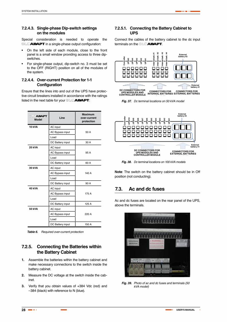
7.2.5.1. Connecting the Battery Cabinet to UPS
Connect the cables of the battery cabinet to the dc input terminals on the .
DC CONNECTORS FOR UPS MODULES AND
CONTROLLER MODULECONNECTORS FOR
INTERNAL BATTERIES
External battery #1
External battery #2
Con
trol
ler
UP
S#5
UP
S#4
UP
S#3
UP
S#2
UP
S#1
Inte
rnal
bat
t. #1
Inte
rnal
bat
t. #
2
Inte
rnal
bat
t. #
3
Inte
rnal
bat
t. #
4
CONNECTORS FOR EXTERNAL BATTERIES
Fig. 37. Dc terminal locations on 50 kVA model
DC CONNECTORS FOR UPS MODULES AND
CONTROLLER MODULECONNECTORS FOR
EXTERNAL BATTERIES
External battery #1
External battery #2
UP
S#1
0
UP
S#9
UP
S#8
UP
S#7
UP
S#6
UP
S#5
UP
S#4
UP
S#3
UP
S#2
UP
S#1
Con
trol
ler
Fig. 38. Dc terminal locations on 100 kVA models
Note: The switch on the battery cabinet should be in Off position (not conducting).
7.3. Ac and dc fuses
Ac and dc fuses are located on the rear panel of the UPS, above the terminals.
Fig. 39. Photo of ac and dc fuses and terminals (50 kVA model)

29
SYSTEM INSTALLATION
SALICRU
DC FUSE BUS
AC FUSE BUS
BATT. ± 432 V
UPS#1
UPS#1
SYST.CONTLLR.
SYST.CONTLLR.
UPS#2
UPS#2
UPS#3
UPS#3
UPS#4
UPS#4
UPS#5
UPS#5
BYPASS 3x400 V
50 Hz
INPUT3x400 V
50 Hz
OUTPUT3x400 V
50 Hz
Fig. 40. Diagram of ac and dc fuses and terminals (50 kVA model)
Fig. 41. Fusibles AC y DC y terminales (mod. 100 kVA)
DC FUSE BUS
AC FUSE BUS
AC FUSE BUS
BATT. ± 432 VBYPASS 3x400 V
50 Hz
INPUT3x400 V
50 Hz
OUTPUT3x400 V
50 Hz
UPS#1
UPS
#2
UPS
#3
UPS
#4
UPS
#1
UPS
#5
UPS
#7
UPS
#6
UPS
#8
UPS
#9
SYST
.CO
NTL
LR.
SYST.CONTLLR.
SYST
.CO
NTL
LR.
UPS
#10
UPS#2UPS#3UPS#6
UPS#10 UPS#9 UPS#8 UPS#7
UPS#5 UPS#4
UPS
#2
UPS
#3
UPS
#4
UPS
#1
UPS
#5
UPS
#7
UPS
#6
UPS
#8
UPS
#9
UPS
#10
Fig. 42. Diagram of ac and dc fuses and terminals (100 kVA model)
7.4. Special Terminal Connections
This section describes the special-purpose terminal con-nections of the Freestyle.
Special-purpose connections are located inside the static switch tray. To access the special-purpose terminals, the static switch tray must be partially slid out (after discon-nection of the UPS from all voltage sources and following standard safety procedures). shows a view from above of the open static switch tray and the location of the special terminal connections.
provides a closer look at the connections.
Note: There are also some special purpose connections on the rear of the controller module.
Fig. 43. Special purpose terminals in STSW tray
STSW communication bus
Load on bypass (N.O.)
1 2
E.P.O. (N.O.)
1 2
Batt. CB trip coil (N.O.)
1 2
External N.O.EPO switch
Trip coil
Power contacts
Contacts close during bypass
operation
Battery C.B.
To controller
CB aux. contacts provide
"on/off" indication
STSW communications bus
Load on Bypass (N.O.)
E.P.O. (N.O.)
Bat. C.B. trip coil (N.O.)
Trip coilContacts close during Bypass
operationExternal N.O. EPO switch
C.B. aux. contacts provide “On/Off” indication to controller
Power contacts
Battery C.B.
Fig. 44. Close-up of special purpose terminals
7.4.1. Load on Bypass AlarmThis output dry contact is Normally Open, and closes when the UPS transfers the load to bypass ( ). The dry contact reopens again when the UPS returns to inverter mode.
7.4.2. Battery Trip CoilThe battery trip coil terminals are intended to be connected to the trip coil of the battery circuit breaker ( ). If this is done and the EPO switch is activated, the Free-style sends a pulse of 230 V to the battery circuit breaker trip coil, causing the battery circuit breaker to turn OFF.
Use of the battery trip coil means that not only will use of the EPO switch cut all ac output from the UPS, it will also turn off the battery circuit breaker.
30
SYSTEM INSTALLATION
USER'S MANUAL
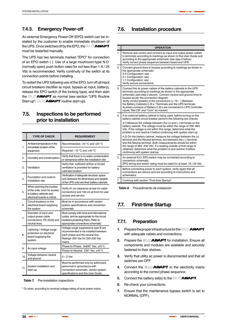
7.4.3. Emergency Power-offAn external Emergency Power-Off (EPO) switch can be in-stalled by the customer to enable immediate shutdown of the UPS. Once switched off by the EPO, the must be restarted manually.
The UPS has two terminals marked "EPO" for connection of an EPO switch ( ). Use of a large mushroom-type N.O. (normally open) push button rated for not less than 1 A / 24 Vdc is recommended. Verify continuity of the switch at its connection points before installing.
To restart the UPS following use of the EPO, turn off all input circuit breakers (rectifier ac input, bypass ac input, battery), release the EPO switch (if the locking type), and then start the as normal (see section "UPS Routine Start-up", routine start-up).
7.5. Inspections to be performed prior to installation
TYPE OF CHECK REQUIREMENT
1.Ambient temperature in the immediate location of the equipment
Recommended: +15 °C and +25 °C
Required: –10 °C and +40 °C
2. Humidity and condensationVerify that there is no water condensation or dampness within the installation site
3. VentilationVerify that sufficient airflow or forced ventilation is provided for battery cabinets location
4.Foundation and route to installation site
Verification of adequate structure, space and clearance for dimensions and weights of the UPS units and their battery cabinets
5.
When planning the location of the units, room for access to battery cabinets and electrical boards is critical.
Verify 91 cm clearance at rear for cable connections and 100 cm at front for user access and service
6.Circuit breakers on the electrical board supplying the system
Must be in accordance with vendor system specifications and connection schematic
7.
Diameter of input and output power cable connections, PE (Gnd) and neutral lines.
Must comply with local and international codes, and be appropriate for the circuit breakers protecting them. Refer to appropriate connections schematic.
8.
Lightning / Voltage surge protection on electrical board supplying the system.
Voltage surge suppressors type B are recommended to be installed between each phase and the neutral line: Ratings: 300 Vac for 220-230 Vac mains.
9. Ac input voltage Phase-to-Phase: 3x400* Vac, ±10 %
Phase-to-Neutral: 230* Vac, ±10 %
10.Voltage between neutral and ground
0 – 2 Vac
11.System installation and start-up
Must be performed only by authorized personnel in accordance with connection schematic, vendor system specifications and this User Guide
Table 7. Pre-installation inspections
* Or other, according to nominal voltage rating of local power mains.
7.6. Installation procedure
OPERATION
1. Remove rear covers and connect ac input and output power cables to terminals according to markings as shown in this User Guide and according to the appropriate schematic (see step 2 below). Verify correct phase sequence between board and UPS.
2. Connect ground lines to busses according to markings as shown in the appropriate schematic: 3-3 Configuration: see . 3-1 Configuration: see .1-1 Configuration: see .Verify secure connections.
3. Connect the dc power cables of the battery cabinets to the UPS terminals according to markings as shown in the appropriate schematic (see step 2 above). Connect neutral and ground lines to busses as per the connection diagram. Verify correct polarity of the connections (+ / N / –) Between the Battery Cabinets C.B.s / Terminals and the UPS terminals. Auxiliary contacts of Battery C.B.s are connected to UPS Controller inputs “Bat CB” and “Com” as marked.
4. If an external battery cabinet is being used, before turning on the battery cabinet circuit breaker perform the following two checks:
4.1) Measure the voltage between the (+) and (–) terminals on the battery cabinet. The voltage must be within the range of 768–864 Vdc. If the voltage is not within this range, determine what the problem is and resolve it before continuing with system start-up.
4.2) On the battery cabinet, measure the voltage between the (+) terminal and the Neutral terminal, and between the (–) terminal and the Neutral terminal. Both measurements should be within the range of 384–432 Vdc. If a reading outside of that range is obtained, determine what the problem is and resolve it before continuing with system startup.
5. An external N.O. EPO switch may be connected according to connection schematic. EPO wiring and switch rating must be rated for at least 1A / 24 Vdc.
6. Before connecting power to each system, verify again that all connections are secure and are according to instructions and schematics.
7. Continue with section "First-time Startup".
Table 8. Procedimiento de instalación
7.7. First-time Startup
7.7.1. Preparation1. Prepare the proper infrastructure for the
with adequate cables and connections.
2. Prepare the for installation. Ensure all components and modules are available and securely fastened to their shelves.
3. Verify that utility ac power is disconnected and that all switches are OFF.
4. Connect the to the electricity mains according to the correct phase sequence.
5. Connect the battery set(s) to the .
6. Re-check your connections.
7. Ensure that the maintenance bypass switch is set to NORMAL (OFF).
31
SYSTEM INSTALLATION
SALICRU
7.7.2. OperationNote: Before first setting up the UPS, make sure that the load is not connected.
When applying power to the , the system automatically runs the startup process without a need to press the On/Off button.
1. Turn the ac input and ac bypass switch ON and wait (for about 2 minutes) for the to ini-tialize.
2. The start-up sequence will begin and the control panel will show the following sequence. (The details of the display may vary from what is shown in the illustrations below, depending on your system's particulars.).
At start-up, the following screen sequence appears:
UPS POWER+SC25270105
W E L C O M E ! ! !
Fig. 45. Start-up screen 1
WARNING !!!SYSTEM RUNNING IN:
S I L I C O N M O D E (JP2 – IN)--------PLEASE NOTIFY SUPERVISOR--------
Fig. 46. Start-up screen 2
In “SILICON MODE”, commands issued through the Control Panel are executed immediately.
Operators should exercise caution.
Note: In , “Silicon mode” indicates that the configura-tion jumper is installed, thus allowing for modifications.
WAIT FOR RESULTS…STATIC RAM: PASSED R.T CLOCK: PASSEDEEPROM – 1: PASSEDEEPROM – 3: PASSED DC SUPPLIES: PASSED
Fig. 47. Start-up screen 3
S Y S T E M I N I T I A L I Z I N GSC25270105
PLEASE WAIT FOR COUNT DOWN TO FINISH45 SECONDS LEFT
Fig. 48. Start-up screen 4
During this step, the LEDs are also checked sequentially.
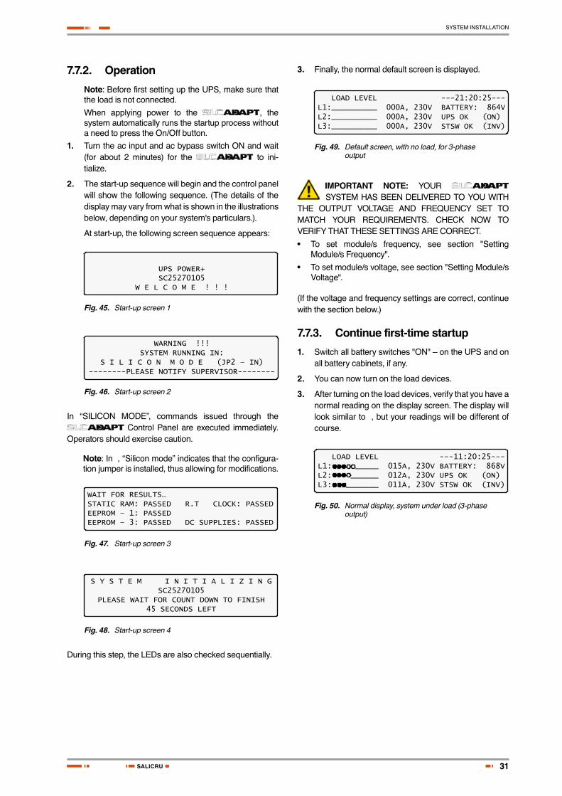
3. Finally, the normal default screen is displayed.
LOAD LEVEL ---21:20:25---L1:__________ 000A, 230V BATTERY: 864VL2:__________ 000A, 230V UPS OK (ON)L3:__________ 000A, 230V STSW OK (INV)
Fig. 49. Default screen, with no load, for 3-phase output
IMPORTANT NOTE: YOUR SYSTEM HAS BEEN DELIVERED TO YOU WITH
THE OUTPUT VOLTAGE AND FREQUENCY SET TO MATCH YOUR REQUIREMENTS. CHECK NOW TO VERIFY THAT THESE SETTINGS ARE CORRECT.
• To set module/s frequency, see section "Setting Module/s Frequency".
• To set module/s voltage, see section "Setting Module/s Voltage".
(If the voltage and frequency settings are correct, continue with the section below.)
7.7.3. Continue first-time startup1. Switch all battery switches "ON" – on the UPS and on
all battery cabinets, if any.
2. You can now turn on the load devices.
3. After turning on the load devices, verify that you have a normal reading on the display screen. The display will look similar to , but your readings will be different of course.
LOAD LEVEL ---11:20:25---L1: _____ 015A, 230V BATTERY: 868VL2: ______ 012A, 230V UPS OK (ON)L3: _______ 011A, 230V STSW OK (INV)
Fig. 50. Normal display, system under load (3-phase output)

32
SYSTEM INSTALLATION
USER'S MANUAL
7.8. Checks to be performed following initial startup
VERIFICATION REQUIREMENT RLT.
1.
Ac input voltage during operation under load. Take measurements on the input terminals of the system.
Phase-to-phase: Not less than 2 % below no-load values measured in item 5 below.
L1-L2L2-L3L3-L1
Phase to Neutral: Not less than 2 % below no-load values measured in item 5 below.
L1-NL2-NL3-N
2.
With no load on the system, measure current circulation between the units.
Irst should be < 5 A
3.
With no load on the system, measure the dc voltage of the system.
Total dc voltage between + and – terminals should be between 850 V and 880 V.
(+) - (–)
4.
Voltage between neutral and ground during operation under load On the input terminals of the system.
0–2 Vac
5. System output voltage.
380/400/415 V +/- 2 %or other according to system specifications.
6. Total system load / output current.
Verify that the system is not overloaded in relation to system specifications.
7. Correct and orderly operation.
Verify that the UPS is operating normally in accordance with this User Guide and that no alarms or fault indications are evident.
Table 9. Checklist following initial startup
Note: It is the responsibility of the customer to notify your vendor to receive approval for any deviations from these requirements.
TO COMPLETE THIS INSTALLATION CHECKLIST, PLEASE SKETCH ON THE FOLLOWING PAGE A DI-AGRAM OF YOUR SYSTEM'S CONNECTIONS, OR INCLUDE A FORMAL CONNECTION SCHEMATIC, AND FAX THE TABLE 7 AND 9 TO YOUR VENDOR.

33
SYSTEM INSTALLATION
SALICRU
7.9. Connection diagram
Fig. 51. Connection diagram (for completion by the customer)

34
SYSTEM INSTALLATION
USER'S MANUAL
7.10. Configuration
Perform the following configuration steps from the Control Panel.
7.10.1. Check Configured ModulesVerify that the number of configured modules matches the desired output power, and verify that the number of redun-dant modules is correct. Modify as needed.
1. Press Ent to reach the Main Menu.
1> SYSTEM 4> HISTORY 7> SETUP2> UPS MODULE 5> BATTERY 8> STATIC SW3> SELFTEST 6> ALARM 9> _____NAVIGATE: <UP, DOWN> 1 SELECT: <ENTER>
Fig. 52. Main Menu
2. From the Main Menu select option 7, Setup
POWER+ System SetupType in Level-1 PASSWORD, THEN – ENTERYour privilege will expire after 15 min.PASSWORD:________
Fig. 53. Password access
3. Select Service, option 8:
[Main Menu > SETUP > (password) > Ent]
1> Alarm set 5> Time 9> Silicon2> Module conf. 6> Site3> Battery 7> Password #14> Charge 8> Service
Fig. 54. Setup menu
4. Select Configure, option 5, to configure the modules:
[Main Menu > SETUP > (password) > Ent > Service]
1> ------ 4> DryOut Test 7> --------2> UPSs 5> Configure 8> Powr.Calib3> ------- 6> En/Dis shar 9> SC2012..Select, then Enter
Fig. 55. Service menu
5. Select # UPSs (total), option 2, to specify the total number of modules in the system:
[Main Menu > SETUP > (password) > Ent > Service > Configure]
1> # OF UPSs (redundancy) 5> Dry, Alarms2> # OF UPSs (total) 6> Calibration3> # OF BATT 7> Parallel/StandAlone4> Static Switch Setup 8> REM COMMAND
Fig. 56. Configure menu
6. Use the arrow keys to specify the total number of mod-ules installed in the , and then press Ent:
[Main Menu > SETUP > (password) > Ent > Service > Configure > # OF UPSs (total)]
Set number of UPSs (total)
04 (02 redundant)
Fig. 57. # of UPSs (Total)
7. Select 1, # of UPSs (Redundancy) in to specify the number of modules used for redundancy:
[Main Menu > SETUP > (password) > Ent > Service > Configure > # OF UPSs (redundancy)]
Set number of UPSs (Redundancy)
01 (04 total)
Fig. 58. # of UPSs (Redundancy)
Note: The redundant modules are designated to re-place other system modules when they stop working. For example, a 100-kVA system with 10 modules of which two are configured for redundancy can deliver a maximum of 80 kVA.
7.10.2. Check Total Ampere-Hours
This procedure is designed to ensure that the total capacity of the batteries attached to matches the definition of the total capacity in the System Controller.
1. Check the total capacity of the installed batteries at-tached to Power+.
2. Verify that the same value is specified in the System Controller. If not, modify the definition in the System Controller to match the capacity of the installed bat-teries.
To check the capacity defined in the System Controller:
1. From the Main Menu select option 5, Battery.
[Main Menu > BATTERY]
Battery capacity: 0020AhCharge mode : FloatingEq. running time: --------Charge current : 053.0A
Fig. 59. Battery status
The battery status panel displays the battery capacity de-fined in the System Controller.
To set the battery capacity in the System Controller to a different value:

35
SYSTEM INSTALLATION
SALICRU
1. Note the current value of battery capacity:
[Main Menu > BATTERY > > > > > ]
1> Battery#1: 020 Ah Total Cap.: 0020 Ah
Fig. 60. Battery capacity
2. Adjust the battery capacity to correspond to that of the attached batteries, and press Ent:
[Main Menu > SETUP > (password) > Battery > Capacity 0020AH) > Set Capacity of Battery #1
Battery #01 Capacity setup 10 -990Capacity :020 Ah
Fig. 61. Set battery capacity
3. Repeat step 1 above to verify the set battery capacity.
7.10.3. Set Date and Time and Serial Number
To verify the date and time set in the System Controller and make sure that they are correct:
1. Use the and keys to select the year, month, day, hour, minute, or second you wish to modify, then use the and keys to set the correct value for the selected item. Press Ent:[Main Menu > SETUP > (password) > Time]
Set real time
Year Month Day Hour Min Sec2011 09 30 23 58 00
Fig. 62. Date and time
2. Enter the serial number of the Power+ system in the System Controller, and then press Ent:[Main Menu > SETUP > (password) > Site]
Site number: 013271
Fig. 63. Site number
Note: The serial number of is on a bar-code label at the top of the unit, on the left hand side, near the front.
7.10.4. Define the IP Address of the UPS
This procedure assigns the Power+ an address within the domain of the customer's computer network.
1. Obtain IP, gateway, and mask addresses from the system administrator of the organization for the Power+ system.
2. Select Set IP ADDRESS in the Network menu:
[Main Menu > SETUP > (password) > Ent > Service > SC2012 > Network]
1> Set IP ADDRESS 157.211.000.2532> Set GATEWAY 157.211.000.2513> Set MASK 255.255.255.0004> Store 5> SNMP factor Select:1
Fig. 64. Network menu
3. Use the arrow keys to set the IP address, and then press Ent:[Main Menu > SETUP > (password) > Ent > Service > SC2012 > Network > Set IP ADDRESS]
Set IP ADDRESS
157.211.000.252
Fig. 65. IP Address
4. Use the arrows keys to set the gateway and press Ent.[Main Menu > SETUP > (password) > Ent > Service > SC2012 > Network > Set GATEWAY]
Set GATEWAY 157.211.000.251
Fig. 66. Gateway
5. Select Store:
[Main Menu > SETUP > (password) > Ent > Service > SC2012 > Network]
1> Set IP ADDRESS 157.211.000.2532> Set GATEWAY 157.211.000.2513> Set MASK 255.255.255.0004> Store 5> SNMP factor Select:1
Fig. 67. Network menu
Entered information is now stored in the controller.

36
SYSTEM INSTALLATION
USER'S MANUAL
7.11. Testing
Perform the following tests on the unit:
7.11.1. Blackout TestThis test is designed to verify the operation of Power+ in the event of a blackout, when no ac power is supplied to the UPS.
1. Turn all ac input to the system Off (turn Off ac input switches to both Bypass and Rectifier).
2. Measure the phase-to-neutral voltage for each output phase. The measurements should all be 230 V (or as specified).
7.11.2. Cold StartThis test is designed to verify the operation of the UPS after all input power (both mains and battery) has been shut off and the UPS is powered up with battery only and no ac input.
1. Turn all ac and dc input to the system Off, so that there are no voltages at any of the inputs to the UPS.
2. Turn On the switch to the dc input (from the batteries) only.
3. Wait approximately 2 minutes for Power+ to initialize (see Section "First-time Startup").
4. Measure the phase-to-neutral voltage for each output phase. The measurements should all be 230 V (or as specified).
5. Turn On the ac inputs to the system.
7.11.3. Test under LoadThis test is designed to verify the operation of Power+ under load.
1. Connect the load.
2. Measure the ac input voltage during operation under load. Take the measurements at the output terminals of Power+ (phase-to-phase between L1-L2, L2-L3, and L3-L1 and phase-to-neutral at L1, L2, and L3). Phase-to-phase and phase-to neutral voltage should be not less that 2% below no-load values.
3. Check and record the total system load (output cur-rent) and make sure that Power+ is not overloaded with respect to system specifications.
4. Ascertain correct and orderly operation. Verify that Power+ is operating normally and that no alarms or fault indications are present.
7.11.4. Check IP Communication with Controller (optional)
This test is designed to verify that the System Controller is properly configured for communication and that the Web server built-in into the System Controller is functioning properly.
1. Use an RJ45-to-RJ45 crossed cable to attach a notebook computer to the Ethernet (RJ45) port on the rear panel of the System Controller.
2. Configure the Network Connections of the lap top computer to make sure the computer is in the same domain as the UPS. (Note: the details of the following configuration procedure are for the Windows XP operating system. The configuration procedure will differ for other operating systems.)
a. Right click on the My Network Places icon on your desktop and select Properties.
Fig. 68. Network Connections screen
b. When the Network Connections screen appears, right-click on Local Area Connection and select Properties.
Fig. 69. Local Area Connection Properties screen

37
SYSTEM INSTALLATION
SALICRU
c. When the Local Area Connection Properties screen appears, in the This connection uses the following items window scroll down to Internet Protocol (TCP/IP) and double click on it.
Fig. 70. Internet Protocol (TCP/IP) Properties screen
d. When the Internet Protocol (TCP/ITP Properties screen appears, click the Use the following IP address button and enter IP address and Subnet mask in the appropriate fields. Leave Default gateway blank. Make sure that the first three groups of numbers in the IP address (192.212.118 in the above example) are the same as those of the domain in which the UPS is installed, and that the last number (31 in the above example) is different (it can be any number from 0 to 255, other than the one already assigned to the UPS).
e. Click OK twice to complete the network connection.
3. Open your browser on the laptop computer and enter the IP address of the System Controller in the brows-er’s address field to verify that you can reach the Web server on the System Controller. The system displays the main GMaCi screen, similar to the one shown below.
Fig. 71. Main Screen of built-in web server
7.11.5. Test Wing OptionIf Wing has been installed in the UPS, this test is designed to check that it is working properly by sending an SMS message through the Web interface of Wing to a specified phone number.
1. Click the Send SMS button on the left sidebar of the Main Screen of the built-in web server.
Fig. 72. Login screen of built-in web server
2. When the login screen appears, enter admin for both User name and Password, and click OK.
Fig. 73. SMS screen
3. A record of messages transmitted and received by the controller is recorded.
Note: Only the controller can send SMS messages or alarms.

38
UPS ROUTINE START-UP
USER'S MANUAL
8. UPS Routine Start-up
8.1. Start-up after Shutdown
This section describes the start-up procedures for the operator after a shutdown. After shut-down, the UPS on, Alarm and Load indicators will flash.
After a normal shutdown the display screen indicates a load of zero amps, the UPS status is “OK, OFF”; the Static Switch status is “OK, BYP”.
LOAD LEVEL ---22:21:18---L1:__________ 000A, 230V BATTERY: 864VL2:__________ 000A, 230V UPS OK (OFF)L3:__________ 000A, 230V STSW OK (BYP)
Fig. 74. Main screen after a power shutdown
Fig. 75. Main screen after a power shutdown indication
1. Press twice on the On/Off button on the upper right of the system controller panel.
Wait about 2 minutes for the POWER+ to start up.
The following screen is displayed:
LOAD LEVEL ---22:21:18---L1:__________ 000A, 230V BATTERY: 864VL2:__________ 000A, 230V UPS OK (ON)L3:__________ 000A, 230V STSW OK (INV)
Statusindications
Status indica-tions
Fig. 76. Main screen at power-up
The UPS status should now be “OK, ON” and the STSW status “OK INV”.
If instead of the STSW status being “OK, INV” it continues to be “OK, BYP”, check the Static Switch panel to verify that the inverter is running.
If the inverter indicator on the Static Switch panel is OFF:
• Press the Inv/Byp button on the static switch panel to switch the inverter ON and wait for the indicator to light.
• Press the Inv/Byp button on the lower right of the control panel.
Fig. 77. Normal operation indication
1. Connect the load and observe the results on the dis-play.
LOAD LEVEL ---11:20:25---L1: _____ 015A, 230V BATTERY: 864VL2: ______ 012A, 230V UPS OK (ON)L3: _______ 011A, 230V STSW OK (INV)
Load level bar graph
Outputcurrent
Outputvoltage
Currenttime
Batteryvoltage
Statusindications
Load Level Bar Graph
Output current
Output voltage
Current time
Battery voltage
Status in-dications
Fig. 78. Main screen results
2. Observe that the “dot” bar graph now indicates the load presence and relative power consumption. Filled dots indicate kW; filled dots plus empty dots indicate kVA (apparent power).
START-UP IS NOW COM-PLETE.

39
UPS ROUTINE START-UP
SALICRU
8.2. UPS shutdown (switching to bypass)
1. Switch the load OFF.
2. Press twice on the On/Off button.
3. Wait 2 minutes for the to shut down. The control screen will indicate UPS OK (OFF).
LOAD LEVEL ---22:21:18---L1:__________ 000A, 230V BATTERY: 864VL2:__________ 000A, 230V UPS OK (OFF)L3:__________ 000A, 230V STSW OK (BYP)
Fig. 79. Main screen – switching to bypass
Note: This does NOT switch the entire OFF. Power is still delivered to the load but in bypass.
Fig. 80. Bypass indication
8.3. UPS total shutdown (no ac output)
1. Switch the load OFF.
2. Press and hold the On/Off button for 10 seconds.
3. The control screen will indicate UPS OK (OFF).
LOAD LEVEL ---23:14:40---L1:__________ 000A, 230V BATTERY: 864VL2:__________ 000A, 230V UPS OK (OFF)L3:__________ 000A, 230V STSW Warning !
Fig. 81. Main screen – total shutdown
Fig. 82. UPS off indication

40
UPS CONTROL PANEL
USER'S MANUAL
9. UPS control panel
The user manages the system via a touch-pad control panel and an LCM (LCD) display on the front panel of the controller. The control panel serves as the user’s primary interface with the system. Messages, warn-ings, and error conditions are relayed to the user through the display, LEDs and audible alarms.
Fig. 83. Control panel
The remainder of the current chapter contains a quick-reference summary of the functions available through the
control menus.
Chapter "UPS Menu functions in detail" illustrates in detail the functions available through the
control menus.
9.1. Quick-Reference Summary of UPS Menu Functions
The following flowcharts detail the structure of the menus.
The symbol directs you to a following chart. For ex-ample, means "go to the diagram labelled M.7.3. Di-agram M.7.3 illustrates sub-option 3 of Main Menu option 7.
MAIN Menu
SYSTEM â
Screen 1.0
Screen 2.0
Screen 3.0
Screen 4.0
Screen 5.0
Screen 6.0
Screen 7.0
Screen 8.0
Screen 9.0
ç
ç
ç
ç
ç
ç
ç
ç
UPS MODULES â
SELFTEST â
HISTORY â
BATTERY â
ALARM â
SETUP â
STATIC SWITCH â
Not used â
Voltage, current, other msmnts for each UPS module
Perform system self-test
Display log of system events
Alarm status
(â)(á)
(â)(á)
(â)(á)
(â)(á)
(â)(á)
(â)(á)
(â)(á)
(â)(á)
M.1
M.5
M.7
M.8
Fig. 84. Main Menu

41
UPS CONTROL PANEL
SALICRU
(Main Menu) SYSTEM â
Screen 1.0
(â )ç
M.1
Main Menu option 1, the "System" screen. Press the or keys to display various measurements.
• Battery current & voltage.
• Ac input & output current & voltage.
• Total operating time, ses-sion time, # of boots.
• Controller jumper set-tings.
• Controller internal volt-ages.
• Battery temperature.• Status of: batt. fuses,
EPO, user dry contacts 1 - 4.
• “PD dialog” (for techni-cian).
Fig. 85. System menu
(Main Menu) BATTERY â
Screen 5.0
(â )ç
M.5
Main Menu option 5
Displays:
• Battery capacity in Ah. • Charging current.• Battery voltage.• Result of last battery test.• Days before next batt.
test.
Fig. 86. Battery menu
ALARMS SETâ
Screen 7.1
Screen 7.2
Screen 7.3
Screen 7.4
Screen 7.5
Screen 7.6
Screen 7.7
Screen 7.8
Screen 7.9
ç
ç
ç
ç
ç
ç
ç
ç
MODULE CONF â
BATTERY â
CHARGE â
TIME â
SITE â
PASSWORD â
SERVICE â
SILICON â
Set alarm thresholds
Set module operational parms.
Set battery parms.
Set floating (charging) voltage
Set date & time
Set site #
Change password
Deep configuration and adjustments
(â)(á)
(â)(á)
(â)(á)
(â)(á)
(â)(á)
(â)(á)
(â)(á)
(â)(á)
(â)(á)
(â)(á)
(â)(á)
(â)(á)
(â)(á)
M.7.1
M.7.2
M.7.3
M.7.8
M.7.9
(Main Menu) SETUP â
Screen 7.0
M.7
SETUP Menu
(â)(á)
Fig. 87. Setup menu
(Main Menu) STATIC SW. â
Pantalla 8.0
(â )ç
M.8
Main Menu option 8
Displays:
• Inverter voltage.• Bypass voltage.• Output current.• Static switch status bytes.
Fig. 88. Static switch menu

42
UPS CONTROL PANEL
USER'S MANUAL
(Setup Menu) ALARM SET â
Screen 7.1
(â )ç
Options 1 on the Setup Menu
Set:1. Ac high & low alarm
thresholds, Ac alarm hysteresis.
2. Batt. end, batt. low, batt. hi voltages.
7. Over temp., under temp.
9. Integration factor.
M.7.1
Fig. 89. Alarm set sub-menu
(Setup Menu) MODULE CONF â
Screen 7.2
(â )ç
Options 2 on the Setup Menu
Set:1. # of phases.2. Modules frequency:
hard (dip dep.) / 50 Hz / 60 Hz.
3. Modules output voltage.
4. Update: apply any changes made in 1, 2, 3 above.
5. Output adj.: fine tune voltage of each phase.
6. Frequency limits: define acceptable freq. variation.
7. Calibrate dc voltage.8. Calibrate ac voltages.
M.7.2
Fig. 90. Module configuration sub-menu
(Setup Menu) BATTERY â
Screen 7.3
(â )ç
Opción 3 on the Setup menu
Set:1. Batt. test voltage.2. Batt. test alarm
voltage.3. Batt. current limit.4. Temperature compen-
sation.5. Batt. test: set test
period and max test time.
6. Set Batt. capacity in Ah.
7. Query auto batt. test values and status.
8. Enab/disab shutdown on long ac fail, current sens., batt temp. sens.
M.7.3
Fig. 91. Battery Menu
--------- â
Screen 7.8.1
Screen 7.8.2
Screen 7.8.3
Screen 7.8.4
Screen 7.8.5
Screen 7.8.6
Screen 7.8.7
Screen 7.8.8
Screen 7.8.9
ç
ç
ç
ç
ç
ç
ç
ç
UPSs â
---------- â
DRY OUT TEST â
CONFIGURE â
ENA./DIS. SHARING â
---------- â
POWER CALIBRATION â
SC2012 â
Not in use
Set UPS modules on/off
Not in use
Test output dry contacts 1 - 6
Deeper configuration
Enable/disable current sharing
- Restart controller.- Restore factory settings.- Remote communic. settings.
Not in use
Set power correction factor
(â)(á)
(â)(á)
(â)(á)
(â)(á)
(â)(á)
(â)(á)
(â)(á)
(â)(á)
(â)(á)
(â)(á)
(Setup Menu) SERVICE â
Screen 7.8
SERVICE Menu
(â)(á)
M.7.8
M.7.8.5
Fig. 92. Service sub-menu

43
UPS CONTROL PANEL
SALICRU
# of redundant UPS modules â
Screen 7.8.5.1
Screen 7.8.5.2
Screen 7.8.5.3
Screen 7.8.5.4
Screen 7.8.5.5
Screen 7.8.5.6
Screen 7.8.5.7
Screen 7.8.5.8
ç
ç
ç
ç
ç
ç
ç
# of UPS modules (total) â
# of batt. â
STSW setup â
Dry, alarms â
Calibration â
Parallel / Stand-alone â
Remote commands, enable/disableâ
Set # of redundant UPS modules
Set total # of UPS modules
- Set STSW mask.- Configure bypass as normal
or controlled
Set # of battery strings
- Associate alarms with output dry contacts 1 - 6.
- Enable/disable individ. alarms
Dc (battery) current calibration
Is the system to operate as a stand-alone unit or in parallel?
Enable/disable ability to modify UPS settings via
remote comm. link.
(â)(á)
(â)(á)
(â)(á)
(â)(á)
(â)(á)
(â)(á)
(â)(á)
(â)(á)
(Service Menu) CONFIGURE â
Screen 7.8.5
CONFIGURE Menu
(â)(á)
M.7.8.5
Fig. 93. Configure sub-sub-menu
--------- â
Screen 7.9.1
Screen 7.9.2
Screen 7.9.3
Screen 7.9.4
Screen 7.9.5
Screen 7.9.6
ç
ç
ç
ç
ç
Reset Log â
Defaults â
--------- â
Reset total time â
Last maint. set â
Not in use
Erases all log entries
Not in use
- Restore factory defaults.- Restore user defaults.- Save user defaults.
Set accumulated operation time clock to zero
Set date of last maintenance
(â)(á)
(â)(á)
(â)(á)
(â)(á)
(â)(á)
(â)(á)
(Setup Menu) SILICON â
Screen 7.9
SILICON Menu
(â)(á)
M.7.9
Fig. 94. Silicon sub-menu

44
UPS MENU FUNCTIONS IN DETAIL
USER'S MANUAL
10. UPS Menu functions in detail
This chapter describes the functions available through the Main Menu and its submenus.
Note: If you are viewing this file in PDF format, it is pos-sible to search for text in the displayed screens. This eases finding the desired screen.
10.1. Main Menu
Press the Enter button (Ent) to display the main menu.
Note: To return to the main menu at any time, press the Escape button (Esc) and then Ent.
1> SYSTEM 4> HISTORY 7> SETUP2> UPS MODULE 5> BATTERY 8> STATIC SW3> SELFTEST 6> ALARM 9> _____NAVIGATE: <UP, DOWN> 1 SELECT: <ENTER>
Fig. 95. Main Menu
1> SYSTEM General information such as voltages, currents etc.
2> UPS MODULE Information for a specific UPS module.
3> SELFTEST Self checking of the Controller's components (supply, RTC, memory).
4> HISTORY History log events (last 255 events, dated and timed).
5> BATTERY Charging / discharging voltages and currents, battery test etc.
6> ALARM Detailed alarm status.
7> SETUP Configuring the system (number of modules, alarm, time etc.).
8> STATIC SW Static Switch data.
Table 10. Main Menu Options
10.2. “System” Option
SYSTEM â
Screen 1.0
Screen 2.0
Screen 3.0
Screen 4.0
Screen 5.0
Screen 6.0
Screen 7.0
Screen 8.0
ç
ç
ç
ç
ç
ç
ç
UPS MODULE â
SELFTEST â
HISTORY â
BATTERY â
ALARM â
SETUP â
STATIC SW. â
(â)(á)
MAIN MENU OPTIONS SUBMENU OPTIONS
<Ent> Batt. voltage & current Output PF Input PF
Input & output voltage & current, per phase.
Total operating time, current ses-sions op. time, number of boots.
Display the settings of jumpers 1, 2, 3, 6, 9.
Controller internal voltages.
Battery temperature.
Status of battery fuse & user dry contacts.
"PD dialog" (for technicians).
Fig. 96. Main menu option 1 ("System")
1. The SYSTEM option (option 1) shows the dc voltages and current (positive, negative and summary):
[Main Menu > SYSTEM]
BATT CURR: -----> TOTAL +053.0ABATT POS.: 430V BATT +053.2A (0531)BATT NEG.: 441VBATT VOLT: 871V
Fig. 97. System dc voltages
2. View the current output power factors:
[Main Menu > SYSTEM > ]
OUTPUT L1 L2 L3 TOTALKVA 000.4 000.2 000.2 000.8KW 000.0 000.0 000.0 000.0P.F. 0.00 0.00 0.00 0.00
Fig. 98. Output power factor 1

45
UPS MENU FUNCTIONS IN DETAIL
SALICRU
3. View the current input power factor:
[Main Menu > SYSTEM > > ]
INPUT L1 L2 L3 TOTALKVA 001.5 001.5 001.5 004.5KW 000.0 000.0 000.0 000.0P.F. 1.00 1.00 1.00 0.00
Fig. 99. Input power factor 1
4. View the three-phase input and output total voltage and current:
[Main Menu > SYSTEM > ]
PHASE: -L1-- -L2-- -L3—IN: 230V/022.0A 231V/022.0A 235V/021.0AOUT: 230V/021.0A 230V/021.0A 230V/021.0A----- TOTAL UPS IN/OUT MEASUREMENTS ----
Fig. 100. Overall phase voltages/currents
5. View the total time, current session time, and boots so far:
[Main Menu > SYSTEM > ]
TOTAL TIME: 19771 HOURS CURRENT SESS.: 13075 HOURS BOOTS SO FAR: 00010 TIMES
Fig. 101. Elapsed time
6. View the system jumper settings without remote panel:
[Main Menu > SYSTEM > ]
JMP: JMP1, JMP2, JMP3, JMP6 and JMP9 =IN 1. NOT HARD SILICON 2. SILICON MODE 6. NO RMT PAN. 12369 3. CAPACITY LOW 9. AC: 230V
Fig. 102. Jumper settings WITHOUT remote panel
7. View the system jumper settings with remote panel:
[Main Menu > SYSTEM > ]
JMP: JMP1, JMP2, JMP3, JMP6 and JMP9 =IN 1. NOT HARD SILICON 2. SILICON MODE 6. Remote pan. 12369 3. CAPACITY LOW 9. AC: 230V
Fig. 103. Jumper settings WITH remote panel
Note: In and , “Silicon mode” indicates that the configu-ration jumper is installed, thus allowing for modifications. “Hard Silicon” indicates that the factory defaults hard reset jumper is installed. This is required only at the factory or whenever software reset fails. Refer to section for a de-tailed description of jumpers.
8. View the internal controller voltages:
[Main Menu > SYSTEM > ]
5VDC : 5.19V CONTROLLER INTERNAL12VDC: 12.01V VOLTAGES5VP : GOOD5V2 : GOOD -12VDC: GOOD
Fig. 104. Internal controller voltages
9. View battery parameters:
[Main Menu > SYSTEM > ]
BATTERY CHARGE LEVEL: 010Ah 050%WHILE TOTAL CAPACITY: 020AhREMAINING BACKUP: 0010 MINUTESBATTERY TEMPERATURE: 12°C
Fig. 105. Battery parameters
Nota: : The data displayed in depends on the options in-stalled and configured. See and .
10. View status of the fuses:
[Main Menu > SYSTEM > ]
BATT FUSE: BAD EMERGENCY: OPENUSER-1: OPEN USER-4: OPENUSER-2: OPEN 7: OPENUSER-3: OPEN 8: OPEN
Fig. 106. Fuse status
11. View communication with the converter in the transmit mode (for Technicians):
[Main Menu > SYSTEM > ]
PD DIALOG: UPS #01T>c0 42 00 00 d8 00 00 00 00 00 00 00 00 00 00 00 00 00 00 aa
Fig. 107. Communication with inverter – transmit
12. View communication with the converter in the receive mode (for Technicians):
[Main Menu > SYSTEM > ]
R<e0e0 0900 0003 0003 0003 e874 1074 1074 2f37 5362 0000 0200 0100 0310 f077 0000 0000 0000 0000 0000 0000 0000 0000 0000 0000 52 52
Fig. 108. Communication with inverter – receive
13. Press Ent to return to the Main Menu ( ).

46
UPS MENU FUNCTIONS IN DETAIL
USER'S MANUAL
10.3. “UPS module” Option
To view voltage and current measurements and other information for each UPS module:
1. Use the and keys to scroll between UPS modules. The display shows the voltage and current measure-ments for each module (see ).
2. Scroll and keys to view additional information for the specific module chosen.
SYSTEM â
Screen 1.0
Screen 2.0
Screen 3.0
Screen 4.0
Screen 5.0
Screen 6.0
Screen 7.0
Screen 8.0
ç
ç
ç
ç
ç
ç
ç
ç
ç
UPS MODULE â
SELFTEST â
HISTORY â
BATTERY â
ALARM â
SETUP â
STATIC SW. â
(â)(á)
MAIN MENU OPTIONS SUBMENU OPTIONS
Select UPS #01/10 Input & Output voltage & current per
phase
Select UPS #02/10 Input & Output voltage & current per
phase
Select UPS #03/10 Input & Output voltage & current per
phase
.
.
.
Select UPS #10/10 Input & Output voltage & current per
phase
Battery voltages & Technician parameters
Technician parameters
Fig. 109. Main Menu option 2 (“UPS Module”)
1. The first screen to appear after selecting the UPS Module:
[Main Menu > UPS MODULE]
Next screens show data on all UPSs.Use up, down arrow keys to select a UPS.
Use left, right arrow keysto view different UPS parameters.
Fig. 110. LCD Panel – select a UPS
2. View the input and output voltage and current for each phase of a particular UPS module. Scroll down to view other UPS modules.
[Main Menu > UPS MODULE > ]
PHASE: -L1-- -L2-- -L3—IN: 000V/000.0A 000V/000.0A 000V/000.0AOUT: 000V/000.0A 000V/000.0A 000V/000.0AUPS:# 01/04
Fig. 111. Module phase voltages/currents
3. View the battery voltage for the selected UPS module (the parameters I-ACTIVE and I-BUS are for a techni-cian only).
[Main Menu > UPS MODULE > > ]
BATT VOLT I-ACTIVE I- BUSBATT+: 216V L1 000 L1 000BATT-: 216V L2 000 L2 000UPS: #01/04 L3 000 L3 000
Fig. 112. Battery voltages & technician parameters
10.4. “Self-test” Option
You can run a self-test at any time without interfering in the normal operation of the . A self-test is also initiated by the itself each day at midnight.
SYSTEM â
Screen 1.0
Screen 2.0
Screen 3.0
Screen 4.0
Screen 5.0
Screen 6.0
Screen 7.0
Screen 8.0
ç
ç
ç
ç
ç
ç
ç
UPS MODULE â
SELFTEST â
HISTORY â
BATTERY â
ALARM â
SETUP â
STATIC SW. â
(â)(á)
MAIN MENU OPTIONS SUBMENU OPTIONS
Results screen
Fig. 113. Main Menu option 3 (“Self Test”)

47
UPS MENU FUNCTIONS IN DETAIL
SALICRU
The failure of a self-test sets on the self-test alarm. The self-test alarm can only be cleared by a subsequent successful self-test, or it can be cleared manually by a maintenance technician.
Powering the down and up, for example, does not clear the self-test alarm. This is because the failure of a self-test is considered a serious event that should not be “forgotten”. A self-test failure is also recorded in the alarm log.
[Main Menu > SELFTEST]
Wait for results…STATIC RAM: PASSED R.T CLOCK: PASSEDEEPROM – 1: PASSEDEEPROM – 3: PASSED DC SUPPLIES: PASSED
Fig. 114. Result screen from self-test
10.5. “History” (logs) Option
The last 255 events reserved in the LOG are displayed, as shown in :
SYSTEM â
Screen 1.0
Screen 2.0
Screen 3.0
Screen 4.0
Screen 5.0
Screen 6.0
Screen 7.0
Screen 8.0
ç
ç
ç
ç
ç
ç
ç
UPS MODULE â
SELFTEST â
HISTORY â
BATTERY â
ALARM â
SETUP â
STATIC SW. â
(â)(á)
MAIN MENU OPTIONS SUBMENU OPTIONS
Time, date, value, message and message # for last 255 events
ç
More detailed information for technicians
Fig. 115. Main Menu option 4 (“History”)
1. Navigate the LOG by scrolling using the and keys:
[Main Menu > HISTORY]
TIME DATE VALUE MESSAGE #14:36:16 28.06.07 099.1V IN->STSWCM 25414:37:01 28.06.07 502.0V OUT>OVLOAD 25512:27:26 27.06.07 120.0V IN->UPS-CM 000
Fig. 116. History logs
2. View more details by pressing the key:
[Main Menu > HISTORY > ]
TIME DATE 1 2 3 4 5 6 7 8 #14:36:16 28.02.10 25414:37:01 28.02.10 25512:27:26 27.02.10 000
Fig. 117. History log scroll
# Message Explanation
01 UPSMAJ More than 1 UPS Module is sending an alarm or fault warning
02 UPSMIN Single UPS Module is sending an alarm or fault warning
03 ------ N.A.
04 ------ N.A.
05 LOADBP Load is now running on bypass. See Table 12 on page 78 to interpret the LOADBP value.
06 VIBRA_ Alarm(s) vibrating. Alarm is frequently raised and lowered. Ignore to avoid loading the log filling up.
07 OVTEMP Excess temperature
08 OUTFLT No ac output to load
09 BAT-HI Excessive battery voltage
10 ------ N.A.
11 BATEND End of battery backup. Battery is discharged to shutdown limit
12 BATLOW Low battery voltage
13 STSWRN Static Switch Warning or alarm
14 E.P.O. Emergency Power Off is active
15 EQ-HST Battery is currently charging in equalizing mode, dc voltage is temporarily increased
16 BATFLT Batteries failed last test
17 USER-1 User 1 input open
18 USER-2 User 2 input open
19 USER-3 User 3 input open
20 AC-BRN Input ac supply Brown Out
21 ACIN_H Ac input excessive
22 ACFAIL Ac input failure
23 STSWCM Static Switch does not respond
24 SLFFLT Last controller self-test failed
25 BAT-CB Battery Circuit Breaker Open
26 CURSHR Current Sharing fault, load current is not equally divided between modules
27 UPSOUT Fault (no current) in 1 or more output stage
28 UPSHDN UPS shutdown by EPO, Battery Discharge, ON/OFF pressed
29 OVLOAD Load current is high
30 UPS-CM One or more UPS’s not responding
31 STRTUP Startup time-stamp
32 ------ N.A.
Table 11. Log Messages
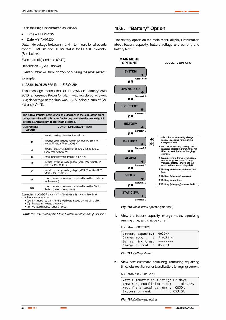
48
UPS MENU FUNCTIONS IN DETAIL
USER'S MANUAL
Each message is formatted as follows:
• Time – HH:MM:SS
• Date – YY:MM:DDData – dc voltage between + and – terminals for all events except LOADBP and STSW status for LOADBP events. (See below.)
Even start (IN) and end (OUT).
Description – (See above).
Event number – 0 through 255, 255 being the most recent.
Example:
11:23:56 10.01.28 865 IN → E.P.O. 254.
This message means that at 11:23:56 on January 28th 2010, Emergency Power Off alarm was registered as event 254; dc voltage at the time was 865 V being a sum of (V+ -N) and (V- -N).
The STSW transfer code, given as a decimal, is the sum of the eight components listed in this table. Each component has its own weight if detected, and a weight of zero if not detected.
COMPONENTWEIGHT
CONDITION DESCRIPTION
1 Inverter voltage blackout for >3 ms.
2 Inverter peak voltage low (brownout) (<185 V for 3x400 V, <92.5 V for 3x208 V).
4 Inverter peak voltage high (>400 V for 3x400 V, >200 V for 3x208 V).
8 Frequency beyond limits (45-65 Hz).
16 Inverter average voltage low (<185 V for 3x400 V, <92.5 V for 3x208 V).
32 Inverter average voltage high (>260 V for 3x400 V, >130 V for 3x208 V)..
64 Load transfer command received from the controller (not manual).
128 Load transfer command received from the Static Switch (manual key press).
Example: If LOADBP data = 67 = (64+2+1), this means that three conditions were present:
• (64)Instructiontotransfertheloadwasissuedbythecontroller.• (2)Lowpeakvoltagedetected.• (1)Voltageblackoutencountered.
Table 12. Interpreting the Static Switch transfer code (LOADBP)
10.6. “Battery” Option
The battery option on the main menu displays information about battery capacity, battery voltage and current, and battery test.
SYSTEM â
Screen 1.0
Screen 2.0
Screen 3.0
Screen 4.0
Screen 5.0
Screen 6.0
Screen 7.0
Screen 8.0
ç
ç
ç
ç
ç
ç
ç
UPS MODULE â
SELFTEST â
HISTORY â
BATTERY â
ALARM â
SETUP â
STATIC SW. â
(â)(á)
MAIN MENU OPTIONS SUBMENU OPTIONS
<Ent> Battery capacity, charge mode, equalizing running time, charge current.
Next automatic equalizing, re-maining equalizing time, total rec-tifier current, battery (charging) current.
Max. estimated time left, battery test in progress time, battery voltage, battery (charging) cur-rent, last test result, days left.
Battery status and status of last test.
Battery (charging) currents.
Battery capacities.
Battery (charging) current limit.
Fig. 118. Main Menu option 5 (“Battery”)
1. View the battery capacity, charge mode, equalizing running time, and charge current:
[Main Menu > BATTERY]
Battery capacity: 0020AhCharge mode : FloatingEq. running time: --------Charge current : 053.0A
Fig. 119. Battery status
2. View next automatic equalizing, remaining equalizing time, total rectifier current, and battery (charging) current:
[Main Menu > BATTERY > ]
Next automatic equalizing: 02 daysRemaining equalizing time: ___ minutesRectifiers total current : 0050ABattery current : 053.0A
Fig. 120. Battery equalizing

49
UPS MENU FUNCTIONS IN DETAIL
SALICRU
3. View the maximum estimated time left, battery test in progress time, battery voltage, battery (charging) cur-rent, last test result, and days left:
[Main Menu > BATTERY > > ]
Max/estim time left : 00:00:00 /--:--:--Battery test in progress for: 00:00:00Batt. volt: 860.0V Batt.current: 008Last test: PASSED Days left: 027
Fig. 121. Time left
4. View battery status and status of the last test:
[Main Menu > BATTERY > > > ]
1> Battery#1: PASSED Last test: PASSED
Fig. 122. Last test
5. View battery (charging) current:
[Main Menu > BATTERY > > > > ]
Batt1 curr: 052.1A Batt curr: 052.1A
Fig. 123. Battery current
6. View battery capacity:
[Main Menu > BATTERY > > > > > ]
1> Battery#1: 020 Ah Total Cap.: 0020 Ah
Fig. 124. Battery capacity
Nota: , and show the individual batteries on the left and the overall total on the right. In the examples shown above, only one battery is installed..
7. View battery (charging) current limit:
[Main Menu > BATTERY > > > > > > ]
1> Battery#1: Current limit: 53A
Fig. 125. Battery current limit
10.7. “Alarm” Option
Alarms are displayed—there are 32 in all. In addition, there are some screens for use by a technician.
SYSTEM â
Screen 1.0
Screen 2.0
Screen 3.0
Screen 4.0
Screen 5.0
Screen 6.0
Screen 7.0
Screen 8.0
ç
ç
ç
ç
ç
ç
ç
UPS MODULE â
SELFTEST â
HISTORY â
BATTERY â
ALARM â
SETUP â
STATIC SW. â
(â)(á)
MAIN MENU OPTIONS SUBMENU OPTIONS
Alarms 01 - 12 are displayed.
Alarms 13 - 24 are displayed.
Alarms 25 - 32 are displayed.
Relay status.
Dry contact #01 assignment.
.
.
.
Dry contact #06 assignment.
Fig. 126. Main Menu option 6 (“Alarm”)
1. View alarms 01-12:
A + or – before an alarm name indicates the alarm is enabled or disabled, respectively.
An asterisk (*) after an alarm name indicates that the alarm is active.
[Main Menu > ALARM]
01 – 03 +UPSMAJ:* +UPSMIN: +MSTR>1:04 – 06 +DCRPCY: +LOADBP: -VIBRA-:07 – 09 +OVTEMP: +OUTFLT: +BAT-HI:10 – 12 +------: +BATEND: +BATLOW:
Fig. 127. Alarms 01-12

50
UPS MENU FUNCTIONS IN DETAIL
USER'S MANUAL
2. View alarms 13-24:
[Main Menu > ALARM > ]
13 – 15 +STSWRN: +E.P.O.:* -EQ-HST:16 – 18 +BATFLT:* +USER-1: -USER-2:19 – 21 +USER-3: +AC-BRN: +ACIN-H:22 – 24 +ACFAIL: +STSWCM:* +SLFFLT:*
Fig. 128. Alarms 13-24
3. View alarms 25-32:
[Main Menu > ALARM > > ]
25 – 27 +BAT-CB: +CURSHR:* -UPSOUT:28 – 30 +UPSHDN:* +OVLOAD: -UPS-CM:31 – 32 +STRTUP: +USER-4:
Fig. 129. Alarms 25-32
10.8. “Setup – Alarm Set” Option
SYSTEM â
Screen 1.0
Screen 2.0
Screen 3.0
Screen 4.0
Screen 5.0
Screen 6.0
Screen 7.0
Screen 8.0
ç
ç
çç
ç
ç
çç
ç
ç
ç
ç
ç
ç
ç
UPS MODULE â
SELFTEST â
HISTORY â
BATTERY â
ALARM â
SETUP â
STATIC SW. â
(â)(á)
(â)(á)
(â)(á)
(â)(á)
(â)(á)
(â)(á)
(â)(á)
(â)(á)(â)(á)
(â)(á)
(â)(á)(â)(á)
(â)(á)
MAIN MENU OPTIONS Alarm Set SUBMENU OPTIONS
Password: <<<<<<<<
1) Alarm Set 1) AC VOLT 1) Set AC High & Low Alarm Levels
1) BATEND
1) Over temperature
2) Under temperature
Set integration factor
2) BATLOW
4) BAT-HI
AC alarm setup
Set AC volt alarms hysteresis
Floating charge alarm setup: voltage setting
Floating charge alarm setup: voltage setting
Floating charge alarm setup: voltage setting
Set over temperature alarm value
Set under temperature alarm value
2) Set AC Alarms Hysteresis
2) FLOAT VOLT
7) Temperature
9) Integrat.
Fig. 130. Main Menu option 7 (“Setup – Alarm Set”)

51
UPS MENU FUNCTIONS IN DETAIL
SALICRU
1. To enter Setup, use the default password <<<<<<<< (left arrow key eight times).
[Main Menu > SETUP]
POWER+ System SetupType in Level-1 PASSWORD, THEN – ENTERYour privilege will expire after 15 min.PASSWORD:________
Fig. 131. Level 1 password access
2. Select Alarm set:
[Main Menu > SETUP > (password) > Ent]
1> Alarm Set 5> Time 9> Silicon2> Module Conf. 6> Site3> Battery 7> Password #14> Charge 8> Service 1
Fig. 132. Setup menu
10.8.1. Setting Ac Voltage Alarms
1. Select AC VOLT:
[Main Menu > SETUP > (password) > ALARM SET
1> AC VOLT 5> --------- 9>INTEGRAT.2> FLOAT VOLT 6> ---------3> --------- 7> TEMPERATURE4> --------- 8> ---------
Fig. 133. Alarm setup menu
2. Select Set AC High & Low Alarm Levels:
[Main Menu > SETUP > Ent > (password) > Ent > ALARM SET > AC VOLT]
1> SET AC HIGH & LOW ALARM LEVELS2> SET AC ALARMS HYSTERESIS
PLEASE SELECT 1
Fig. 134. Ac alarms menu
3. Use the arrow keys to update values and press Ent:
[Main Menu > SETUP > Ent > (password) > Ent > ALARM SET > AC VOLT > Set AC High & Low Alarm Levels]
AC VOLT SETUP: NOMINAL 220/230 VAC ---- AC ALARM SETUP ---- AC-LOW AC-HIGH 185V 286V
Fig. 135. Set ac alarm voltage levels
4. Select Set AC Alarms Hysteresis:
[Main Menu > SETUP > Ent > (password) > Ent > ALARM SET > AC VOLT
1> SET AC HIGH & LOW ALARM LEVELS2> SET AC ALARMS HYSTERESIS
PLEASE SELECT 1
Fig. 136. Ac alarms menu
5. Use the arrow keys to set value, press Ent, and then Esc:
[Main Menu > SETUP > Ent > (password) > Ent > ALARM SET > AC VOLT > Set AC Alarms Hysteresis]
SET AC VOLT ALARMS HYSTERESIS VALUE (1 – 20) VOLT
05
Fig. 137. Set ac voltage hysteresis
10.8.2. Setting Battery Floating Voltage Alarm
1. Select FLOAT VOLT:
[Main Menu > SETUP > (password) > ALARM SET]
1> AC VOLT 5> --------- 9>INTEGRAT.2> FLOAT VOLT 6> ---------3> --------- 7> TEMPERATURE4> --------- 8> ---------
Fig. 138. Alarm set menu
2. Select BATEND:
[Main Menu > SETUP > (password) > ALARM SET > FLOAT VOLT]
1> BATEND2> BATLOW3> ------4> BAT-HI SELECT ITEM:1
Fig. 139. Battery floating charge alarm setup menu
3. Use the arrow keys to set BATEND and press Ent:
[Main Menu > SETUP > (password) > ALARM SET > FLOAT VOLT > BATEND]
FLOATING CHARGE ALARM SETUP
VOLTAGE SETTING: 340.0V
Fig. 140. Set BATEND
52
UPS MENU FUNCTIONS IN DETAIL
USER'S MANUAL
4. Select BATLOW:
[Main Menu > SETUP > (password) > ALARM SET > FLOAT VOLT]
1> BATEND2> BATLOW3> ------4> BAT-HI SELECT ITEM:1
Fig. 141. Battery floating charge alarm setup menu
5. Use the arrow keys to set BATLOW and press Ent.:
[Main Menu > SETUP > (password) > ALARM SET > FLOAT VOLT > BATLOW]
FLOATING CHARGE ALARM SETUP
VOLTAGE SETTING: 360.0V
Fig. 142. Set BATLOW
6. Select BAT-HI:
[Main Menu > SETUP > (password) > ALARM SET > FLOAT VOLT]
1> BATEND2> BATLOW3> ------4> BAT-HI SELECT ITEM:1
Fig. 143. Battery floating charge alarm setup menu
7. Use the arrow keys to set BAT-HI, press Ent, and then Esc.:
[Main Menu > SETUP > (password) > ALARM SET > FLOAT VOLT > BAT-HI]
FLOATING CHARGE ALARM SETUP
VOLTAGE SETTING: 475.0V
Fig. 144. Set BAT-HI
10.8.3. Setting Battery Over/Under Temperature Alarms
1. Select TEMPERATURE:
[Main Menu > SETUP > (password) > ALARM SET]
1> AC VOLT 5> --------- 9>INTEGRAT.2> FLOAT VOLT 6> ---------3> --------- 7> TEMPERATURE4> --------- 8> ---------
Fig. 145. Alarm set menu
2. Select OVER TEMPERATURE:
[Main Menu > SETUP > (password) > ALARM SET > Temperature]
1> OVER TEMPERATURE2> UNDER TEMPERATURE
PLEASE SELECT
Fig. 146. Over/Under temperature menu
3. Use the arrow keys to set the battery maximum tem-perature alarm value and press Ent:
[Main Menu > SETUP > (password) > ALARM SET > Temperature > OVER TEMPERATURE]
SET OVER TEMPERATURE ALARM VALUE ( 2 – 99) DEGREES
45
Fig. 147. Set battery maximum temperature alarm
4. Select UNDER TEMPERATURE:
[Main Menu > SETUP > (password) > ALARM SET > Temperature]
1> OVER TEMPERATURE2> UNDER TEMPERATURE
PLEASE SELECT
Fig. 148. Over/Under temperature menu
5. Use the arrow keys to set the battery minimum tem-perature alarm value, press Ent, and then Esc.:
[Main Menu > SETUP > (password) > ALARM SET > Temperature > UNDER TEMPERATURE]
SET OVER TEMPERATURE ALARM VALUE ( 2 – 99) DEGREES
45
Fig. 149. Set battery minimum temperature alarm
10.8.4. Setting Battery Integration Alarm
The Alarm Integration Factor determines the number of times that the controller polls and retries to determine the UPS status before deciding on an error status. Setting the alarm integration factor too low will cause spurious alarms to be generated; conversely, setting the alarm integration factor too high may result in an alarm only being raised when it is already too late to take corrective action.

53
UPS MENU FUNCTIONS IN DETAIL
SALICRU
1. Select INTEGRAT.:
[Main Menu > SETUP > (password) > ALARM SET]
1> AC VOLT 5> --------- 9>INTEGRAT.2> FLOAT VOLT 6> ---------3> --------- 7> TEMPERATURE4> --------- 8> ---------
Fig. 150. Alarm set menu
2. Use the arrow keys to set the integration factor alarm value—press Ent to accept or Esc to discard:
[Main Menu > SETUP > (password) > ALARM SET > INTEGRAT.]
SET INTEGRATION FACTOR (1 – 30)
ENTER = ACCEPT 05 ESC = DISCARD
Fig. 151. Set the integration factor alarm
10.9. “Setup – Module Conf.” Option
SYSTEM â
Screen 1.0
Screen 2.0
Screen 3.0
Screen 4.0
Screen 5.0
Screen 6.0
Screen 7.0
Screen 8.0
ç
ç
ç
ç
ç
ç
ç
ç
ç
ç
ç
ç
ç
ç
ç
ç
ç
UPS MODULE â
SELFTEST â
HISTORY â
BATTERY â
ALARM â
SETUP â
STATIC SW. â
(â)(á)
(â)(á)
(â)(á)
(â)(á)
(â)(á)
(â)(á)
(â)(á)
(â)(á)
(â)(á)
(â)(á)
(â)(á)
(â)(á)
(â)(á)
(â)(á)
(â)(á)
MAIN MENU OPTIONS Module Config. SUBMENU OPTIONS
Password: <<<<<<<<
1) Module Config. 1) Num of fase
2) Module/s frequency
3) Module(s) voltage
4) Update Vo/F/ph
5) Output Adjust
6) Freq. Limits
7) DC Calibra-tion
8) AC Calibra-tion
Set module/s frequency
Set module/s voltage
Update Vo/F/ph settings
Select a phase to adjust
Select a module to adjust
Select a value to adjust
Set frequency limits
1) Calibrate positive voltage
2) Calibrate negative voltage
2) Calibrate OUTPUT voltage
1) Calibrate INPUT voltage
Set positive voltage
Set negative voltage
Calibrate OUTPUT voltage
Calibrate INPUT voltage
Fig. 152. Main Menu option 7 (“Setup – Module Conf.”)

54
UPS MENU FUNCTIONS IN DETAIL
USER'S MANUAL
1. To enter Setup, use the default password <<<<<<<< (left arrow key eight times).
[Main Menu > SETUP]
POWER+ System SetupType in Level-1 PASSWORD, THEN – ENTERYour privilege will expire after 15 min.PASSWORD:________
Fig. 153. Level 1 password access
2. Select Module conf.:
[Main Menu > SETUP > (password) > Ent]
1> Alarm set 5> Time 9> Silicon2> Module conf. 6> Site3> Battery 7> Password #14> Charge 8> Service
Fig. 154. Setup menu
10.9.1. Setting Number of Phases
1. Select Num of phase:
[Main Menu > SETUP > (password) > Module conf.]
1. Num of phase 5.Output Adjust2. Module/s frequency 6.Frequency Limits3. Module/s voltage 7.DC Calibration4. Update Vo/Fr/ph 8.AC Calibration
Fig. 155. Module Config. setup menu
10.9.2. Setting Module/s Frequency
1. Select Module/s frequency:
[Main Menu > SETUP > (password) > Module conf.]
1. Num of phase 5.Output Adjust2. Module/s frequency 6.Frequency Limits3. Module/s voltage 7.DC Calibration4. Update Vo/Fr/ph 8.AC Calibration
Fig. 156. Module Config. setup menu
2. Use the arrow keys to set the module/s frequency, press Ent, and then Esc:
[Main Menu > SETUP > (password) > Module conf. > Module/s frequency]
--- SET MODULE/S FREQUENCY ---SELECT – 1 HARD (DIP DEPEND.)SELECT – 2 SET 50HZ (SELECTED)SELECT – 3 SET 60HZ
Fig. 157. Setting the Module/s frequency
10.9.3. Setting Module/s Voltage
1. Select Module/s voltage:
[Main Menu > SETUP > (password) > Module conf.]
1. Num of phase 5.Output Adjust2. Module/s frequency 6.Frequency Limits3. Module/s voltage 7.DC Calibration4. Update Vo/Fr/ph 8.AC Calibration
Fig. 158. Module Config. setup menu
2. Use the arrow keys to set the module/s voltage, press Ent, and then Esc:
[Main Menu > SETUP > (password) > Module conf. > Module/s voltage]
Module/s voltage 4: 235V1: 220V 5: 240V2: 225V 6: 250V3: 230V (selected) 5: 260V
Fig. 159. Setting the Module/s voltage
10.9.4. Update Voltage/Frequency/Phase
1. Select Update Vo/Fr/ph:
[Main Menu > SETUP > (password) > Module conf.]
1. Num of phase 5.Output Adjust2. Module/s frequency 6.Frequency Limits3. Module/s voltage 7.DC Calibration4. Update Vo/Fr/ph 8.AC Calibration
Fig. 160. Module Config. setup menu
2. Press Ent to update, and then Esc:
[Main Menu > SETUP > (password) > Module conf. > Update Vo/Fr/ph]
Nominal Voltage & Frequencyhave been sent to all modules.
Please verify all modules were updated!Exit this mode by pressing Esc.
Fig. 161. Updating the Module/s voltage/frequency/phase
10.9.5. Output Adjustment
1. Select Output Adjust:
[Main Menu > SETUP > (password) > Module conf.]
1. Num of phase 5.Output Adjust2. Module/s frequency 6.Frequency Limits3. Module/s voltage 7.DC Calibration4. Update Vo/Fr/ph 8.AC Calibration
Fig. 162. Module Config. setup menu

55
UPS MENU FUNCTIONS IN DETAIL
SALICRU
2. Select a phase to adjust and press Ent.:
[Main Menu > SETUP > (password) > Module conf. > Output Adjust]
----- Select a phase to adjust -----Select – 1: L1Select – 2: L2Select – 3: L3
Fig. 163. Select a phase to adjust
3. Using the keys, select a module to adjust, and then Ent.:
[Main Menu > SETUP > (password) > Module conf. > Output Adjust > Ent]
---- Select a module to adjust ---- 01 ---- Use Up/Down, Enter, or Esc. ----
Fig. 164. Select a module to adjust
4. Using the keys select a value to adjust, and then press Ent.:
[Main Menu > SETUP > (password) > Module conf. > Output Adjust > Ent > Ent]
------ Set a value to adjust ------ Phase: 1 00 Module: 01 ---- Use Up/Down, Enter, or Esc. ----
Fig. 165. : Select a value to adjust
10.9.6. Setting Frequency Limits
1. Select Frequency Limits:
[Main Menu > SETUP > (password) > Module conf.]
1. Num of phase 5.Output Adjust2. Module/s frequency 6.Frequency Limits3. Module/s voltage 7.DC Calibration4. Update Vo/Fr/ph 8.AC Calibration
Fig. 166. Module Config. setup menu
2. Using the keys set the frequency limits, press Ent, and then Esc:
[Main Menu > SETUP > (password) > Module conf. > Frequency Limits]
--- Set frequency limits ---1: No Change 4: +/- 3Hz2: +/- 1Hz (slctd) 5: +/- 4Hz3: +/- 2Hz 6: +/- 0.5Hz
Fig. 167. Select the frequency limits
10.9.7. Calibrating DC Voltage
1. Select DC Calibration:
[Main Menu > SETUP > (password) > Module conf.]
1. Num of phase 5.Output Adjust2. Module/s frequency 6.Frequency Limits3. Module/s voltage 7.DC Calibration4. Update Vo/Fr/ph 8.AC Calibration
Fig. 168. Module Config. setup menu
2. Select either Calibrate Positive Voltage or Calibrate Negative Voltage and then press Ent.:
[Main Menu > SETUP > (password) > Module conf. > DC Calibra-tion]
--- MODULES DC VOLTAGE CALIBRATION ---SELECT – 1: Calibrate Positive VoltageSELECT – 2: Calibrate Negative VoltageThen press ENTER to continue
Fig. 169. Calibrate Positive or Negative Voltage
3. Adjust the measured value using the arrow keys, and press Ent to update:
[Main Menu > SETUP > (password) > Module conf. > DC Calibration > Ent]
MODULE V. CALIB – 15 Sec to expire####### Press ENTER To UPDATE ######MEASURED VALUE: 432.0V
Fig. 170. Enter measured value
10.9.8. Calibrating AC Voltage
1. Select AC Calibration:
[Main Menu > SETUP > (password) > Module conf.]
1. Num of phase 5.Output Adjust2. Module/s frequency 6.Frequency Limits3. Module/s voltage 7.DC Calibration4. Update Vo/Fr/ph 8.AC Calibration
Fig. 171. Module Config. setup menu
2. Select either Calibrate INPUT Voltage or Calibrate OUTPUT Voltage and then press Ent.:
[Main Menu > SETUP > (password) > Module conf. > AC Calibration]
--- MODULES AC VOLTAGE CALIBRATION ---SELECT – 1: Calibrate INPUT VoltageSELECT – 2: Calibrate OUTPUT VoltageThen press ENTER to continue
Fig. 172. : Calibrate INPUT or OUTPUT Voltage

56
UPS MENU FUNCTIONS IN DETAIL
USER'S MANUAL
3. Adjust the measured value using the arrow keys, and press Ent to update:
[Main Menu > SETUP > (password) > Module conf. > AC Calibration > Ent]
MODULE V. CALIB – 15 Sec to expire####### Press ENTER To UPDATE ######MEASURED VALUE: 240.0V
Fig. 173. Enter measured value
10.10. “Setup – Battery” Option
SYSTEM â
Screen 1.0
Screen 2.0
Screen 3.0
Screen 4.0
Screen 5.0
Screen 6.0
Screen 7.0
Screen 8.0
ç
ç
ç
ç
ç
ç
ç
ç
ç
ç
ç
ç
ç
ç
ç
ç
ç
ç
ç
ç
ç
ç
ç
UPS MODULE â
SELFTEST â
HISTORY â
BATTERY â
ALARM â
SETUP â
STATIC SW. â
(â)(á)
(â)(á)
(â)(á)
(â)(á)
(â)(á)
(â)(á)
(â)(á)
(â)(á)
(â)(á)
(â)(á)
(â)(á)
(â)(á)
(â)(á)
(â)(á)
(â)(á)
(â)(á)
(â)(á)
(â)(á)
(â)(á)
(â)(á)
(â)(á)
(â)(á)
(â)(á)
MAIN MENU OPTIONS Battery SUBMENU OPTIONS
Password: <<<<<<<<
1) Battery 1) Test-voltage
2) Test-alarm
3) Current-limit...
4) Temp. com-pensat.
5) Battery test...
6) Capacity 0020 AH)
7) 'Auto' Test
8) Enable/Dis Options
1) Current limit value setup
1) Temp. compens. value setup
3) Set ABSOLUT. Max&Min Voltage
2) Set auto battery test period
3) Set auto batt. test top time
1) Activate battery test
1) Set capacity of battery #1
1) ENABLE SHUT-DOWN by long AC fail (Off) <Ent>
2) ENABLE Current Sensors (Off) <Ent>
2) DISABLE Current sensors (On) <Ent>
3) ENABLE Batt. Temp. sensor (Off) <Ent>
3) DISABLE BATT. temp. sensor (On) <Ent>
1) Set ABS. MIN Output Voltage
2) Set ABS. MAX Output Voltage
2) Disable temp. compensation (2.0mV) <Ent>
Battery current limits
2) Current limit - Press <Ent> to ENABLE/DIS.
Set battery test voltage
Set batt. test volt. alarm
Set charge current limit
Set charge current limit
Activate battery test <Ent>
Set Batt. test period
Set top time for bat-tery test
Se battery # N capacity
Battery test results
1) DISABLE SHUT-DOWN by long AC fail (Off) <Ent>
Set ABS. MIN voltage while com-pens.
Set ABS. MAX voltage while com-pens.
Fig. 174. Main Menu option 7 (“Setup – Battery”)
57
UPS MENU FUNCTIONS IN DETAIL
SALICRU
1. To enter Setup, use the default password <<<<<<<< (left arrow key eight times).
[Main Menu > SETUP]
POWER+ System SetupType in Level-1 PASSWORD, THEN – ENTERYour privilege will expire after 15 min.PASSWORD:________
Fig. 175. Level 1 password access
2. Select Battery:
[Main Menu > SETUP > (password) > Ent]
1> Alarm set 5> Time 9> Silicon2> Module conf. 6> Site3> Battery 7> Password #14> Charge 8> Service
Fig. 176. Setup menu
10.10.1. Setting Battery Test Voltage
1. Select Test-Voltage:
[Main Menu > SETUP > (password) > Battery]
1> Test-Voltage 5> Battery test…2> Test Alarm 6> Capacity 0020 AH)3> Current-Limit.. 7> ‘AuTo’ Test4> Temp Compensat. 8> Enable/Dis Options
Fig. 177. Battery setup menu
2. Using the arrow keys, set the battery test voltage and press Ent.:
[Main Menu > SETUP > (password) > Battery > Test Voltage]
BATTERY (test) VOLTAGE SETUP
VOLTAGE SETTING: 352.0V
Fig. 178. Set battery test voltage
10.10.2. Setting Battery Test Voltage Alarm
1. Select Test Alarm:
[Main Menu > SETUP > (password) > Battery]
1> Test-Voltage 5> Battery test…2> Test Alarm 6> Capacity 0020 AH)3> Current-Limit.. 7> ‘AuTo’ Test4> Temp Compensat. 8> Enable/Dis Options
Fig. 179. Battery setup menu
2. Using the arrow keys, set the battery test voltage alarm and press Ent:
[Main Menu > SETUP > (password) > Battery > Test Alarm]
BATTERY (TEST) VOLTAGE ALARM 360.0 V
Fig. 180. : Set battery test voltage alarm
10.10.3. Setting Battery Current Limit
1. Select Current-Limit:
[Main Menu > SETUP > (password) > Battery]
1> Test-Voltage 5> Battery test…2> Test Alarm 6> Capacity 0020 AH)3> Current-Limit.. 7> ‘AuTo’ Test4> Temp Compensat. 8> Enable/Dis Options
Fig. 181. Battery setup menu
2. Select Current Limit Value Setup and press Ent.:
[Main Menu > SETUP > (password) > Battery > Current Limit]
1> Current Limit Value Setup2> Current Limit – Press to ENABLE 1Press ‘2’ to Toggle Enable / Disable
Fig. 182. Current Limit setup menu
3. Select the current limit for each battery and press Ent.:
[Main Menu > SETUP > (password) > Battery > Current Limit >Ent]
1> Set C. Limit of Battery #1 (99A)
Fig. 183. Current limit indication for (each) battery
4. Using the arrow keys, set the current limit for each bat-tery. After the current limit is set for all batteries, press Esc:
[Main Menu > SETUP > (password) > Battery > Current Limit >Ent > Ent]
CHARGE CURRENT LIMIT SETUP
CURRENT LIMIT: 99A
Fig. 184. Set Current limit for (each) battery

58
UPS MENU FUNCTIONS IN DETAIL
USER'S MANUAL
10.10.4. Enable/Disable Battery Current Limit
1. Select Current-Limit:
[Main Menu > SETUP > (password) > Battery]
1> Test-Voltage 5> Battery test…2> Test Alarm 6> Capacity 0020 AH)3> Current-Limit.. 7> ‘AuTo’ Test4> Temp Compensat. 8> Enable/Dis Options
Fig. 185. Battery setup menu
2. Select Current Limit Value Setup and press Ent.:
[Main Menu > SETUP > (password) > Battery > Current Limit]
1> Current Limit Value Setup2> Current Limit – Press to ENABLE 1Press ‘2’ to Toggle Enable / Disable
Fig. 186. Current Limit setup menu
3. Select Current Limit – Press to ENABLE and press Ent to toggle ENABLE/DISABLE:
[Main Menu > SETUP > (password) > Battery > Current Limit]
1> Current Limit Value Setup2> Current Limit – Press to ENABLE 1Press ‘2’ to Toggle Enable / Disable
1> Current Limit Value Setup2> Current Limit – Press to DISABLE 1Press ‘2’ to Toggle Enable / Disable
Fig. 187. Enable/Disable current limit
10.10.5. Setting Temperature Compensation
1. Select Temp Compensat:
[Main Menu > SETUP > (password) > Battery]
1> Test-Voltage 5> Battery test…2> Test Alarm 6> Capacity 0020 AH)3> Current-Limit.. 7> ‘AuTo’ Test4> Temp Compensat. 8> Enable/Dis Options
Fig. 188. Battery setup menu
2. Select Temperature compensation Value Setup and press Ent.:
[Main Menu > SETUP > (password) > Battery > Temp Compensat.]
1> Temperature Compensation Value Setup2> Disable Temp. Compensation (2.0 mV)3> Set ABSOLUTE Max & Min Voltages 1Press ‘2’ to toggle enable / disable
Fig. 189. Temperature compensation setup menu
3. User the arrow keys to set the temperature compensa-tion and press Ent.:
[Main Menu > SETUP > (password) > Battery > Temp Compensat. >Ent]
Temperature Compensation Setup 2.0 – 4.0
Compensate : 2.0 mV/°C (Per Cell)
Fig. 190. Set temperature compensation
10.10.6. Setting Disable Temperature Compensation
1. Select Temp Compensat:
[Main Menu > SETUP > (password) > Battery]
1> Test-Voltage 5> Battery test…2> Test Alarm 6> Capacity 0020 AH)3> Current-Limit.. 7> ‘AuTo’ Test4> Temp Compensat. 8> Enable/Dis Options
Fig. 191. Battery setup menu
2. Select Enable Temp. Compensation and press Ent to toggle enable/disable:
[Main Menu > SETUP > (password) > Battery > Temp.Compensat.]
1> Temperature Compensation Value Setup2> Enable Temp. Compensation ( OFF)3> Set ABSOLUTE Max & Min Voltages 1Press ‘2’ to toggle enable / disable
1> Temperature Compensation Value Setup2> Disable Temp. Compensation (2.0 mV)3> Set ABSOLUTE Max & Min Voltages 1Press ‘2’ to toggle enable / disable
Fig. 192. Enable/Disable temperature compensation
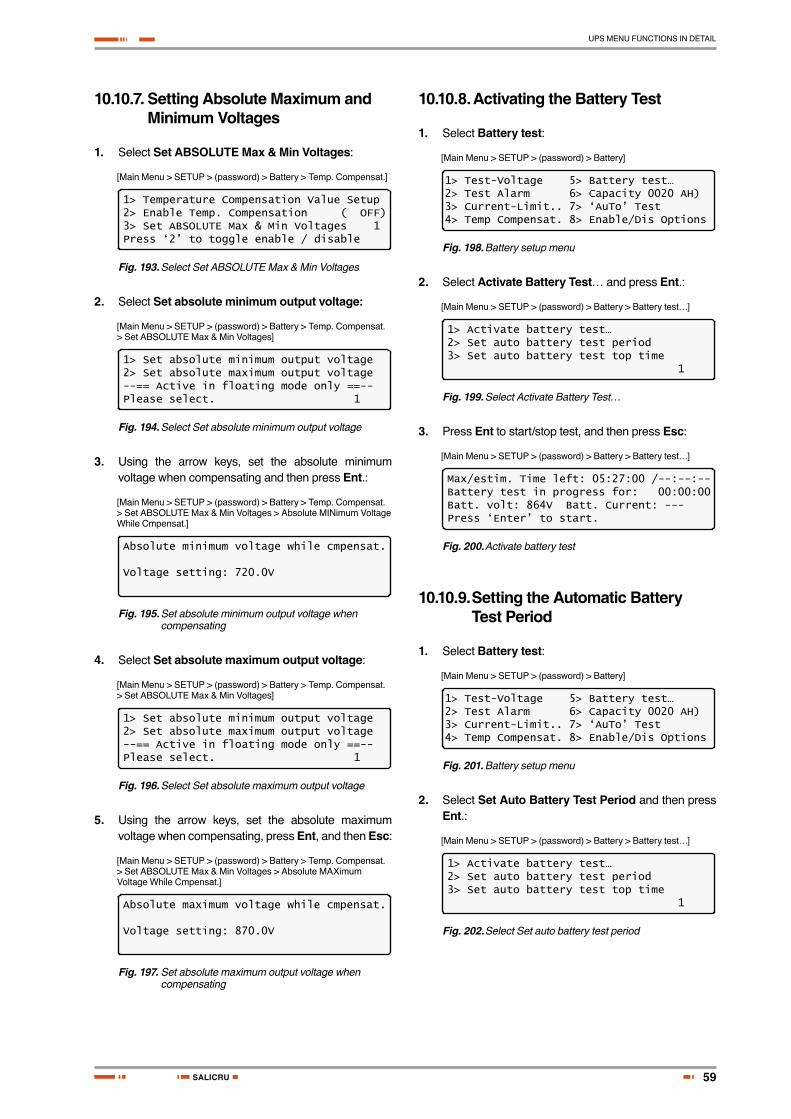
59
UPS MENU FUNCTIONS IN DETAIL
SALICRU
10.10.7. Setting Absolute Maximum and Minimum Voltages
1. Select Set ABSOLUTE Max & Min Voltages:
[Main Menu > SETUP > (password) > Battery > Temp. Compensat.]
1> Temperature Compensation Value Setup2> Enable Temp. Compensation ( OFF)3> Set ABSOLUTE Max & Min Voltages 1Press ‘2’ to toggle enable / disable
Fig. 193. Select Set ABSOLUTE Max & Min Voltages
2. Select Set absolute minimum output voltage:
[Main Menu > SETUP > (password) > Battery > Temp. Compensat. > Set ABSOLUTE Max & Min Voltages]
1> Set absolute minimum output voltage2> Set absolute maximum output voltage--== Active in floating mode only ==--Please select. 1
Fig. 194. Select Set absolute minimum output voltage
3. Using the arrow keys, set the absolute minimum voltage when compensating and then press Ent.:
[Main Menu > SETUP > (password) > Battery > Temp. Compensat. > Set ABSOLUTE Max & Min Voltages > Absolute MINimum Voltage While Cmpensat.]
Absolute minimum voltage while cmpensat.
Voltage setting: 720.0V
Fig. 195. Set absolute minimum output voltage when compensating
4. Select Set absolute maximum output voltage:
[Main Menu > SETUP > (password) > Battery > Temp. Compensat. > Set ABSOLUTE Max & Min Voltages]
1> Set absolute minimum output voltage2> Set absolute maximum output voltage--== Active in floating mode only ==--Please select. 1
Fig. 196. Select Set absolute maximum output voltage
5. Using the arrow keys, set the absolute maximum voltage when compensating, press Ent, and then Esc:
[Main Menu > SETUP > (password) > Battery > Temp. Compensat. > Set ABSOLUTE Max & Min Voltages > Absolute MAXimum Voltage While Cmpensat.]
Absolute maximum voltage while cmpensat.
Voltage setting: 870.0V
Fig. 197. Set absolute maximum output voltage when compensating
10.10.8. Activating the Battery Test
1. Select Battery test:
[Main Menu > SETUP > (password) > Battery]
1> Test-Voltage 5> Battery test…2> Test Alarm 6> Capacity 0020 AH)3> Current-Limit.. 7> ‘AuTo’ Test4> Temp Compensat. 8> Enable/Dis Options
Fig. 198. Battery setup menu
2. Select Activate Battery Test… and press Ent.:
[Main Menu > SETUP > (password) > Battery > Battery test…]
1> Activate battery test…2> Set auto battery test period3> Set auto battery test top time 1
Fig. 199. Select Activate Battery Test…
3. Press Ent to start/stop test, and then press Esc:
[Main Menu > SETUP > (password) > Battery > Battery test…]
Max/estim. Time left: 05:27:00 /--:--:--Battery test in progress for: 00:00:00Batt. volt: 864V Batt. Current: ---Press ‘Enter’ to start.
Fig. 200. Activate battery test
10.10.9. Setting the Automatic Battery Test Period
1. Select Battery test:
[Main Menu > SETUP > (password) > Battery]
1> Test-Voltage 5> Battery test…2> Test Alarm 6> Capacity 0020 AH)3> Current-Limit.. 7> ‘AuTo’ Test4> Temp Compensat. 8> Enable/Dis Options
Fig. 201. Battery setup menu
2. Select Set Auto Battery Test Period and then press Ent.:
[Main Menu > SETUP > (password) > Battery > Battery test…]
1> Activate battery test…2> Set auto battery test period3> Set auto battery test top time 1
Fig. 202. Select Set auto battery test period
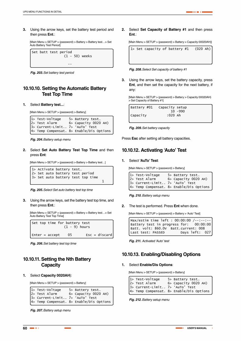
60
UPS MENU FUNCTIONS IN DETAIL
USER'S MANUAL
3. Using the arrow keys, set the battery test period and then press Ent.:
[Main Menu > SETUP > (password) > Battery > Battery test…> Set Auto Battery Test Period]
Set batt test period (1 – 50) weeks
--
Fig. 203. Set battery test period
10.10.10. Setting the Automatic Battery Test Top Time
1. Select Battery test...:
[Main Menu > SETUP > (password) > Battery]
1> Test-Voltage 5> Battery test…2> Test Alarm 6> Capacity 0020 AH)3> Current-Limit.. 7> ‘AuTo’ Test4> Temp Compensat. 8> Enable/Dis Options
Fig. 204. Battery setup menu
2. Select Set Auto Battery Test Top Time and then press Ent:
[Main Menu > SETUP > (password) > Battery > Battery test…]
1> Activate battery test…2> Set auto battery test period3> Set auto battery test top time 1
Fig. 205. Select Set auto battery test top time
3. Using the arrow keys, set the battery test top time, and then press Ent.:
[Main Menu > SETUP > (password) > Battery > Battery test…> Set Auto Battery Test Top Time]
Set top time for battery test (1 – 9) hours
Enter = accept 05 Esc = discard
Fig. 206. Set battery test top time
10.10.11. Setting the Nth Battery Capacity
1. Select Capacity 0020AH):
[Main Menu > SETUP > (password) > Battery]
1> Test-Voltage 5> Battery test…2> Test Alarm 6> Capacity 0020 AH)3> Current-Limit.. 7> ‘AuTo’ Test4> Temp Compensat. 8> Enable/Dis Options
Fig. 207. Battery setup menu
2. Select Set Capacity of Battery #1 and then press Ent.:
[Main Menu > SETUP > (password) > Battery > Capacity 00020AH)]
1> Set capacity of battery #1 (020 Ah)
Fig. 208. Select Set capacity of battery #1
3. Using the arrow keys, set the battery capacity, press Ent, and then set the capacity for the next battery, if any:
[Main Menu > SETUP > (password) > Battery > Capacity 00020AH) > Set Capacity of Battery #1]
Battery #01 Capacity setup 10 -990Capacity :020 Ah
Fig. 209. Set battery capacity
Press Esc after setting all battery capacities.
10.10.12. Activating ‘Auto’ Test
1. Select ‘AuTo’ Test:
[Main Menu > SETUP > (password) > Battery]
1> Test-Voltage 5> Battery test…2> Test Alarm 6> Capacity 0020 AH)3> Current-Limit.. 7> ‘AuTo’ Test4> Temp Compensat. 8> Enable/Dis Options
Fig. 210. Battery setup menu
2. The test is performed. Press Ent when done.
[Main Menu > SETUP > (password) > Battery > ‘Auto’ Test]
Max/estim time left : 00:00:00 /--:--:--Battery test in progress for: 00:00:00Batt. volt: 860.0V Batt.current: 008Last test: PASSED Days left: 027
Fig. 211. Activated ‘Auto’ test
10.10.13. Enabling/Disabling Options
1. Select Enable/Dis Options:
[Main Menu > SETUP > (password) > Battery]
1> Test-Voltage 5> Battery test…2> Test Alarm 6> Capacity 0020 AH)3> Current-Limit.. 7> ‘AuTo’ Test4> Temp Compensat. 8> Enable/Dis Options
Fig. 212. Battery setup menu
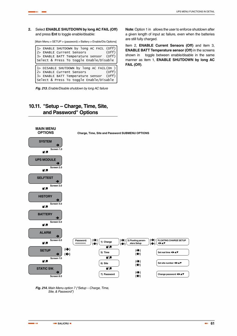
61
UPS MENU FUNCTIONS IN DETAIL
SALICRU
2. Select ENABLE SHUTDOWN by long AC FAIL (Off) and press Ent to toggle enable/disable:
[Main Menu > SETUP > (password) > Battery > Enable/Dis Options]
1> ENABLE SHUTDOWN by long AC FAIL (Off)2> ENABLE Current Sensors (Off)3> ENABLE BATT Temperature sensor (Off)Select & Press To toggle Enable/Disable
1> DISABLE SHUTDOWN by long AC FAIL(On )2> ENABLE Current Sensors (Off)3> ENABLE BATT Temperature sensor (Off)Select & Press To toggle Enable/Disable
Fig. 213. Enable/Disable shutdown by long AC failure
Note: Option 1 in allows the user to enforce shutdown after a given length of input ac failure, even when the batteries are still fully charged.
Item 2, ENABLE Current Sensors (Off) and item 3, ENABLE BATT Temperature sensor (Off) in the screens shown in toggle between enable/disable in the same manner as item 1, ENABLE SHUTDOWN by long AC FAIL (Off).
10.11. "Setup – Charge, Time, Site, and Password" Options
SYSTEM â
Screen 1.0
Screen 2.0
Screen 3.0
Screen 4.0
Screen 5.0
Screen 6.0
Screen 7.0
Screen 8.0
ç
ç
ç
ç
ç
ç
ç
ç
ç
ç
UPS MODULE â
SELFTEST â
HISTORY â
BATTERY â
ALARM â
SETUP â
STATIC SW. â
(â)(á)
(â)(á)
(â)(á)
(â)(á)
(â)(á)
(â)(á)
(â)(á)
MAIN MENU OPTIONS Charge, Time, Site and Password SUBMENU OPTIONS
Password: <<<<<<<< 1) Charge 2) Floating param-
eters SetupFLOATING CHARGE SETUP
Set real time
Set site number
Change password
5) Time
6) Site
7) Password
Fig. 214. Main Menu option 7 (“Setup – Charge, Time, Site, & Password”)

62
UPS MENU FUNCTIONS IN DETAIL
USER'S MANUAL
1. To enter Setup, use the default password <<<<<<<< (left arrow key eight times).
[Main Menu > SETUP]
POWER+ System SetupType in Level-1 PASSWORD, THEN – ENTERYour privilege will expire after 15 min.PASSWORD:________
Fig. 215. Level 1 password access
10.11.1. Setting the Floating Charge
1. Select Charge:
[Main Menu > SETUP > (password) > Ent]
1> Alarm set 5> Time 9> Silicon2> Module conf. 6> Site3> Battery 7> Password #14> Charge 8> Service
Fig. 216. Setup menu
2. Select Floating parameters setup:
[Main Menu > SETUP > (password) > Charge]
1> -----2> Floating parameters setup.3> ----- (Eq:off)4> ----- 1
Fig. 217. Charge setup menu
3. Using the arrow keys, set the floating charge, press Ent, and then press Esc:
[Main Menu > SETUP > (password) > Charge > Floating parameters setup.]
Floating charge setup
Voltage setting: 864.0V
Fig. 218. Set floating charge
10.11.2. Setting the Time
1. Select Time:
[Main Menu > SETUP > (password) > Ent]
1> Alarm set 5> Time 9> Silicon2> Module conf. 6> Site3> Battery 7> Password #14> Charge 8> Service
Fig. 219. Setup menu
2. Using the arrow keys, set the date and time, and then press Ent:
[Main Menu > SETUP > (password) > Time]
Set real time
Year Month Day Hour Min Sec2011 09 30 23 58 00
Fig. 220. Set date and time
10.11.3. Setting the Site Number
1. Select Site:
[Main Menu > SETUP > (password) > Ent]
1> Alarm set 5> Time 9> Silicon2> Module conf. 6> Site3> Battery 7> Password #14> Charge 8> Service
Fig. 221. Setup menu
2. Use the arrow keys to set the site number, and then press Ent.:
[Main Menu > SETUP > (password) > Site]
Site number: 013271
Fig. 222. Set site number
Note: The serial number of Power+ is on a bar-code label at the bottom of the unit, on the left hand side.
10.11.4. Changing the Password
1. Select Password #1:
[Main Menu > SETUP > (password) > Ent]
1> Alarm set 5> Time 9> Silicon2> Module conf. 6> Site3> Battery 7> Password #14> Charge 8> Service
Fig. 223. Setup menu
2. Use the arrow keys to change the password and press Ent, or press Esc to abort:
[Main Menu > SETUP > (password) > Password #1]
Change password
-------- Press Esc to abort
Fig. 224. Change password

63
UPS MENU FUNCTIONS IN DETAIL
SALICRU
10.12. “Setup – Service” Option
(Continued in next figure)
SYSTEM â
Screen 1.0
Screen 2.0
Screen 3.0
Screen 4.0
Screen 5.0
Screen 6.0
Screen 7.0
Screen 8.0
ç
ç
ç
ç
ç
ç
ç
ç
ç
ç
ç
ç
ç
ç
ç
ç
ç
ç
ç
UPS MODULE â
SELFTEST â
HISTORY â
BATTERY â
ALARM â
SETUP â
STATIC SW. â
(â)(á)
(â)(á)
(â)(á)
(â)(á)
(â)(á)
(â)(á)
(â)(á)
(â)(á)
(â)(á)
(â)(á)
(â)(á)
(â)(á)
MAIN MENU OPTIONS Service SUBMENU OPTIONS
Password: <<<<<<<<
8) Service 2) UPSs
4) DryOut Test
5) Configure
6) En/Dis shar
8) Powr.Calib.
9) SC2012...
3) Network...
1) Restart Contro-ller <Ent>
2) Factory Set-tings <Ent>
4) Reset MBX <Ent>
1) Set IP Address
2) Set GATEWAY
3) Set MASK
4) Store <Ent>
5) SNMP Factor
CURRENT SHA-RING RESET:Selec.: 1) Disabled or 2) Enabled <Ent>
UPS Setup <Ent> <Esc>
Set IP ADDRESS <Ent>
Set GATEWAY <Ent>
Set MASK <Ent>
Set SNMP NO COMM Factor value
Set PFC <Ent> <Esc>
Fig. 225. Main Menu option 7 (“Setup – Service”) 1/2

64
UPS MENU FUNCTIONS IN DETAIL
USER'S MANUAL
(Continued from last figure)
ç
ç
ç
ç
ç
ç
ç
ç
ç
ç
(â)(á)
(â)(á)
(â)(á)
(â)(á)
(â)(á)
(â)(á)
(â)(á)
(â)(á)
(â)(á)
(â)(á)
(â)(á)
(â)(á)
(â)(á)
(â)(á)
1) # of UPSs (redundancy)
2) # of UPSs (total)
3) # of BATT.
4) Static Switch Setup
5) DRY, alarms
6) Calibration
7) Parallel/Stand Alone
8) REM Com-mand
1) Set Mask
1) - 6) DryN as-sociation
2) Configure BYPASS
2) DC-I Offset removal
7) Enable/Dis-able alarms
3) DC-I Calibra-tion
Set number of re-dund. UPS modules
Set total number of UPS modules
Set number of batt. string
Set STSW mask <Ent>
Set dry contact assoc. with alarms <Ent>
Enable or disable individual alarms <Ent>
Select 1) Stand Alone or 2) Parallel <Ent>
Remote commands allowable: Select 1) Disable or 2) En-able <Ent>
Enter actual current value for #N current <Ent>
To remove current offsets, first discon-nect batteries and load <Ent> o <Esc>
1) BYPASS normal, no control.
2) BYPASS Control Enabled <Ent>
Fig. 226. Main Menu option 7 (“Setup – Service”) 2/2
1. To enter Setup, use the default password <<<<<<<< (left arrow key eight times).
[Main Menu > SETUP]
POWER+ System SetupType in Level-1 PASSWORD, THEN – ENTERYour privilege will expire after 15 min.PASSWORD:________
Fig. 227. Level 1 password access
2. Select Service:
[Main Menu > SETUP > (password) > Ent]
1> Alarm set 5> Time 9> Silicon2> Module conf. 6> Site3> Battery 7> Password #14> Charge 8> Service
Fig. 228. Setup menu
10.12.1. Setting UPSs
1. Select UPSs:
[Main Menu > SETUP > (password) > Ent > Service]
1> ------ 4> DryOut Test 7> --------2> UPSs 5> Configure 8> Powr.Calib3> ------- 6> En/Dis shar 9> SC2012..Select, then Enter
Fig. 229. Service menu
2. Use the arrow keys to set UPSs, and press Esc when finished:
[Main Menu > SETUP > (password) > Ent > Service > UPSs]
1234++++SET UPSs (UP= ON<+>, DOWN= OFF<->)Enter = Execute Esc= Go back
Fig. 230. Set UPSs

65
UPS MENU FUNCTIONS IN DETAIL
SALICRU
10.12.2. Testing Dry Output Relays
1. Select DryOut Test:
[Main Menu > SETUP > (password) > Ent > Service]
1> ------ 4> DryOut Test 7> --------2> UPSs 5> Configure 8> Powr.Calib3> ------- 6> En/Dis shar 9> SC2012..Select, then Enter
Fig. 231. Service menu
2. Press slowly to test each relay, and press Esc when finished:
[Main Menu > SETUP > (password) > Ent > Service > DryOut Test]
Relay status:Press ‘UP’ and repeat for relay test(04)123456 Contacts 1-6 =ON, =OFF
Fig. 232. Set UPSs
10.12.3. Configuring the UPS
1. Select Configure:
[Main Menu > SETUP > (password) > Ent > Service]
1> ------ 4> DryOut Test 7> --------2> UPSs 5> Configure 8> Powr.Calib3> ------- 6> En/Dis shar 9> SC2012..Select, then Enter
Fig. 233. Service menu
10.12.3.1. Number of Redundant UPSs
1. Select # OF UPSs (redundancy):
[Main Menu > SETUP > (password) > Ent > Service > Configure]
1> # OF UPSs (redundancy) 5> Dry, Alarms2> # OF UPSs (total) 6> Calibration3> # OF BATT 7> Parallel/StandAlone4> Static Switch Setup 8> REM COMMAND
Fig. 234. Service > Configure menu
2. Use the arrow keys to set the number of redundant UPSs and then press Ent:
[Main Menu > SETUP > (password) > Ent > Service > Configure > # OF UPSs (redundancy)]
Set number of UPSs (Redundancy)
01 (04 total)
Fig. 235. Set number of redundant UPSs
10.12.3.2. Total Number of UPSs
1. Select # OF UPSs (total):
[Main Menu > SETUP > (password) > Ent > Service > Configure]
1> # OF UPSs (redundancy) 5> Dry, Alarms2> # OF UPSs (total) 6> Calibration3> # OF BATT 7> Parallel/StandAlone4> Static Switch Setup 8> REM COMMAND
Fig. 236. Service > Configure menu
2. Use the arrow keys to set the total number of UPSs and then press Ent.:
[Main Menu > SETUP > (password) > Ent > Service > Configure > # OF UPSs (total)]
Set number of UPSs (total)
04 (02 redundant)
Fig. 237. Set total number of UPSs
10.12.3.3. Total Number of Batteries
1. Select # OF BATT:
[Main Menu > SETUP > (password) > Ent > Service > Configure]
1> # OF UPSs (redundancy) 5> Dry, Alarms2> # OF UPSs (total) 6> Calibration3> # OF BATT 7> Parallel/StandAlone4> Static Switch Setup 8> REM COMMAND
Fig. 238. Service > Configure menu
2. Use the arrow keys to set the total number of batteries and then press Ent.:
[Main Menu > SETUP > (password) > Ent > Service > Configure > # OF BATT]
Set Number Of Batteries (0 to 3)
02
Fig. 239. Set total number of batteries
10.12.3.4. Setting up the Static Switch
1. Select Static Switch Setup:
[Main Menu > SETUP > (password) > Ent > Service > Configure]
1> # OF UPSs (redundancy) 5> Dry, Alarms2> # OF UPSs (total) 6> Calibration3> # OF BATT 7> Parallel/StandAlone4> Static Switch Setup 8> REM COMMAND
Fig. 240. Service > Configure menu
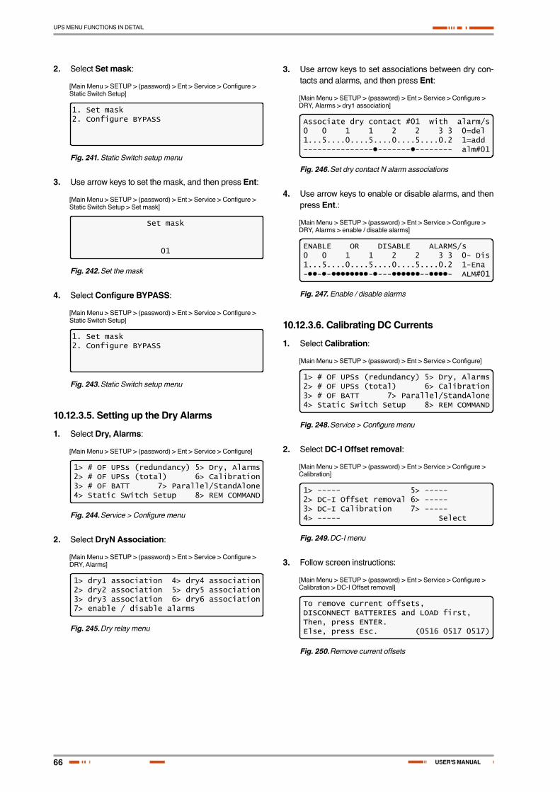
66
UPS MENU FUNCTIONS IN DETAIL
USER'S MANUAL
2. Select Set mask:
[Main Menu > SETUP > (password) > Ent > Service > Configure > Static Switch Setup]
1. Set mask2. Configure BYPASS
Fig. 241. Static Switch setup menu
3. Use arrow keys to set the mask, and then press Ent:
[Main Menu > SETUP > (password) > Ent > Service > Configure > Static Switch Setup > Set mask]
Set mask
01
Fig. 242. Set the mask
4. Select Configure BYPASS:
[Main Menu > SETUP > (password) > Ent > Service > Configure > Static Switch Setup]
1. Set mask2. Configure BYPASS
Fig. 243. Static Switch setup menu
10.12.3.5. Setting up the Dry Alarms
1. Select Dry, Alarms:
[Main Menu > SETUP > (password) > Ent > Service > Configure]
1> # OF UPSs (redundancy) 5> Dry, Alarms2> # OF UPSs (total) 6> Calibration3> # OF BATT 7> Parallel/StandAlone4> Static Switch Setup 8> REM COMMAND
Fig. 244. Service > Configure menu
2. Select DryN Association:
[Main Menu > SETUP > (password) > Ent > Service > Configure > DRY, Alarms]
1> dry1 association 4> dry4 association2> dry2 association 5> dry5 association3> dry3 association 6> dry6 association7> enable / disable alarms
Fig. 245. Dry relay menu
3. Use arrow keys to set associations between dry con-tacts and alarms, and then press Ent:
[Main Menu > SETUP > (password) > Ent > Service > Configure > DRY, Alarms > dry1 association]
Associate dry contact #01 with alarm/s0 0 1 1 2 2 3 3 0=del1...5....0....5....0....5....0.2 1=add-------------------------------- alm#01
Fig. 246. Set dry contact N alarm associations
4. Use arrow keys to enable or disable alarms, and then press Ent.:
[Main Menu > SETUP > (password) > Ent > Service > Configure > DRY, Alarms > enable / disable alarms]
ENABLE OR DISABLE ALARMS/s0 0 1 1 2 2 3 3 0- Dis1...5....0....5....0....5....0.2 1-Ena-------------------------------- ALM#01
Fig. 247. Enable / disable alarms
10.12.3.6. Calibrating DC Currents
1. Select Calibration:
[Main Menu > SETUP > (password) > Ent > Service > Configure]
1> # OF UPSs (redundancy) 5> Dry, Alarms2> # OF UPSs (total) 6> Calibration3> # OF BATT 7> Parallel/StandAlone4> Static Switch Setup 8> REM COMMAND
Fig. 248. Service > Configure menu
2. Select DC-I Offset removal:
[Main Menu > SETUP > (password) > Ent > Service > Configure > Calibration]
1> ----- 5> -----2> DC-I Offset removal 6> -----3> DC-I Calibration 7> -----4> ----- Select
Fig. 249. DC-I menu
3. Follow screen instructions:
[Main Menu > SETUP > (password) > Ent > Service > Configure > Calibration > DC-I Offset removal]
To remove current offsets,DISCONNECT BATTERIES and LOAD first,Then, press ENTER.Else, press Esc. (0516 0517 0517)
Fig. 250. Remove current offsets

67
UPS MENU FUNCTIONS IN DETAIL
SALICRU
4. Select DC-I Calibration:
[Main Menu > SETUP > (password) > Ent > Service > Configure > Calibration]
1> ----- 5> -----2> DC-I Offset removal 6> -----3> DC-I Calibration 7> -----4> ----- Select
Fig. 251. DC-I menu
5. Press Ent to continue:
[Main Menu > SETUP > (password) > Ent > Service > Configure > Calibration > DC-I Calibration]
1> Calibrate Battery #1 Current
Fig. 252. Calibrating DC current
6. Using the arrow keys, set the actual current and then press Ent.:
[Main Menu > SETUP > (password) > Ent > Service > Configure > Calibration > DC-I Calibration > Ent]
CURRENT METER #01 CALIBRATIONEnter the value of the actual current:
02000 (X0.1)A
Fig. 253. Entering actual current
10.12.3.7. Selecting Standalone or Parallel Operation
1. Select Parallel/StandAlone:
[Main Menu > SETUP > (password) > Ent > Service > Configure]
1> # OF UPSs (redundancy) 5> Dry, Alarms2> # OF UPSs (total) 6> Calibration3> # OF BATT 7> Parallel/StandAlone4> Static Switch Setup 8> REM COMMAND
Fig. 254. Service > Configure menu
2. Select Stand Alone or Parallel by using the arrow keys and Ent.:
[Main Menu > SETUP > (password) > Ent > Service > Configure > Parallel/StandAlone]
--- Parallel / Stand-Alone Setup ---SELECT - 1: Stand Alone (selected)SELECT - 2: Parallel
Fig. 255. Setting standalone or parallel operation
10.12.3.8. Enabling/Disabling Remote Commands
1. Select REM COMMAND:
[Main Menu > SETUP > (password) > Ent > Service > Configure]
1> # OF UPSs (redundancy) 5> Dry, Alarms2> # OF UPSs (total) 6> Calibration3> # OF BATT 7> Parallel/StandAlone4> Static Switch Setup 8> REM COMMAND
Fig. 256. Service > Configure menu
2. Enable or disable remote commands by using the arrow keys and Ent.:
[Main Menu > SETUP > (password) > Ent > Service > Configure > REM COMMAND]
--- REMOTE COMMANDS EN / DIS ---SELECT - 1: Disable (selected)SELECT - 2: Enable
Fig. 257. Enabling/disabling remote commands
10.12.4. Enabling/Disabling Current Sharing
1. Select En/Dis shar:
[Main Menu > SETUP > (password) > Ent > Service]
1> ------ 4> DryOut Test 7> --------2> UPSs 5> Configure 8> Powr.Calib3> ------- 6> En/Dis shar 9> SC2012..Select, then Enter
Fig. 258. Service menu
2. Enable or disable current sharing by using the arrow keys and Ent.:
[Main Menu > SETUP > (password) > Ent > Service > Configure > En/Dis shar]
üüü 1: RST CURRSHAR DISBLD:(selected)SELECT 2: RST CURRSHAR ENBLD:
--- CURRENT SHARIN RESET EN / DIS ---
Fig. 259. Enabling/disabling current sharing
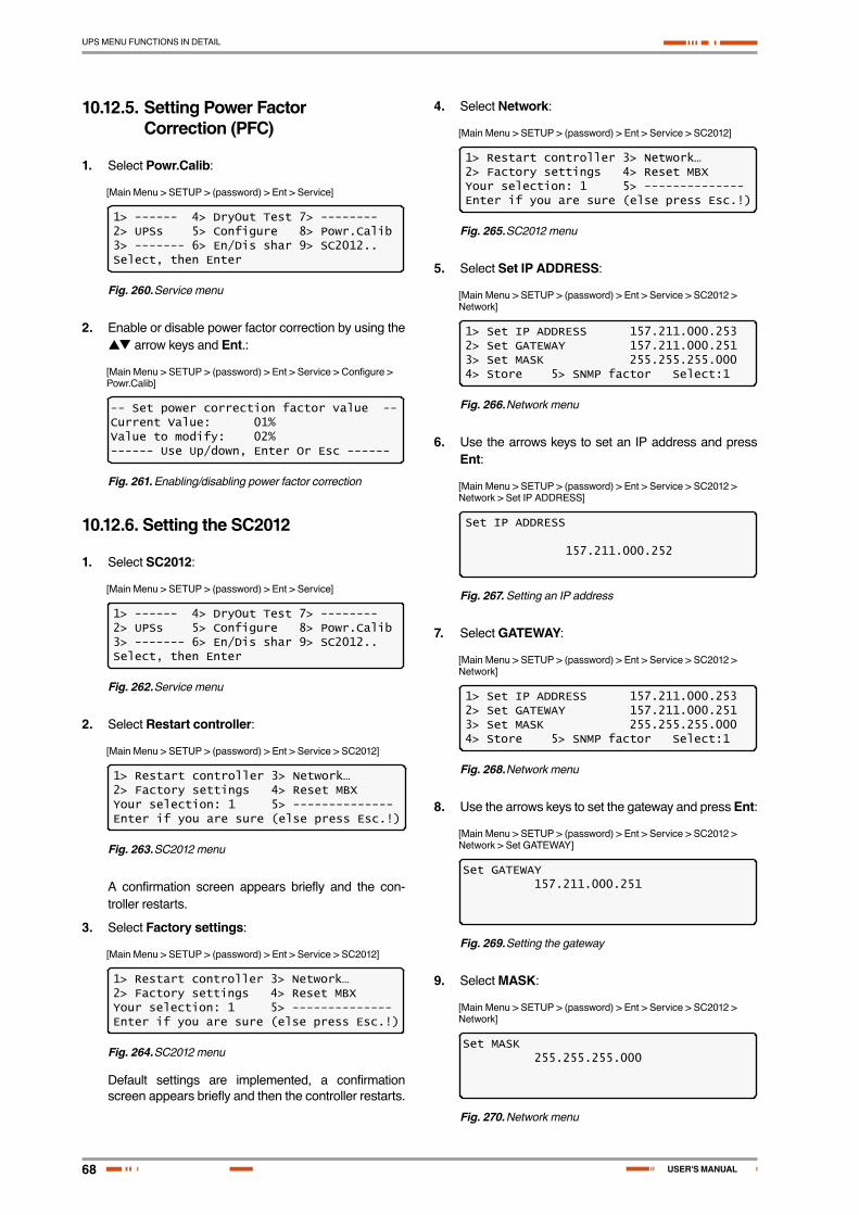
68
UPS MENU FUNCTIONS IN DETAIL
USER'S MANUAL
10.12.5. Setting Power Factor Correction (PFC)
1. Select Powr.Calib:
[Main Menu > SETUP > (password) > Ent > Service]
1> ------ 4> DryOut Test 7> --------2> UPSs 5> Configure 8> Powr.Calib3> ------- 6> En/Dis shar 9> SC2012..Select, then Enter
Fig. 260. Service menu
2. Enable or disable power factor correction by using the arrow keys and Ent.:
[Main Menu > SETUP > (password) > Ent > Service > Configure > Powr.Calib]
-- Set power correction factor value --Current Value: 01%Value to modify: 02%------ Use Up/down, Enter Or Esc ------
Fig. 261. Enabling/disabling power factor correction
10.12.6. Setting the SC2012
1. Select SC2012:
[Main Menu > SETUP > (password) > Ent > Service]
1> ------ 4> DryOut Test 7> --------2> UPSs 5> Configure 8> Powr.Calib3> ------- 6> En/Dis shar 9> SC2012..Select, then Enter
Fig. 262. Service menu
2. Select Restart controller:
[Main Menu > SETUP > (password) > Ent > Service > SC2012]
1> Restart controller 3> Network…2> Factory settings 4> Reset MBXYour selection: 1 5> --------------Enter if you are sure (else press Esc.!)
Fig. 263. SC2012 menu
A confirmation screen appears briefly and the con-troller restarts.
3. Select Factory settings:
[Main Menu > SETUP > (password) > Ent > Service > SC2012]
1> Restart controller 3> Network…2> Factory settings 4> Reset MBXYour selection: 1 5> --------------Enter if you are sure (else press Esc.!)
Fig. 264. SC2012 menu
Default settings are implemented, a confirmation screen appears briefly and then the controller restarts.
4. Select Network:
[Main Menu > SETUP > (password) > Ent > Service > SC2012]
1> Restart controller 3> Network…2> Factory settings 4> Reset MBXYour selection: 1 5> --------------Enter if you are sure (else press Esc.!)
Fig. 265. SC2012 menu
5. Select Set IP ADDRESS:
[Main Menu > SETUP > (password) > Ent > Service > SC2012 > Network]
1> Set IP ADDRESS 157.211.000.2532> Set GATEWAY 157.211.000.2513> Set MASK 255.255.255.0004> Store 5> SNMP factor Select:1
Fig. 266. Network menu
6. Use the arrows keys to set an IP address and press Ent:
[Main Menu > SETUP > (password) > Ent > Service > SC2012 > Network > Set IP ADDRESS]
Set IP ADDRESS
157.211.000.252
Fig. 267. Setting an IP address
7. Select GATEWAY:
[Main Menu > SETUP > (password) > Ent > Service > SC2012 > Network]
1> Set IP ADDRESS 157.211.000.2532> Set GATEWAY 157.211.000.2513> Set MASK 255.255.255.0004> Store 5> SNMP factor Select:1
Fig. 268. Network menu
8. Use the arrows keys to set the gateway and press Ent:
[Main Menu > SETUP > (password) > Ent > Service > SC2012 > Network > Set GATEWAY]
Set GATEWAY 157.211.000.251
Fig. 269. Setting the gateway
9. Select MASK:
[Main Menu > SETUP > (password) > Ent > Service > SC2012 > Network]
Set MASK 255.255.255.000
Fig. 270. Network menu

69
UPS MENU FUNCTIONS IN DETAIL
SALICRU
10. Use the arrows keys to set the mask and press Ent:
[Main Menu > SETUP > (password) > Ent > Service > SC2012 > Network > Set MASK]
Set MASK 255.255.255.000
Fig. 271. Setting the mask
11. Select Store:
[Main Menu > SETUP > (password) > Ent > Service > SC2012 > Network]
1> Set IP ADDRESS 157.211.000.2532> Set GATEWAY 157.211.000.2513> Set MASK 255.255.255.0004> Store 5> SNMP factor Select:1
Fig. 272. Network menu
Entered information is stored.
12. Select SNMP factor:
[Main Menu > SETUP > (password) > Ent > Service > SC2012 > Network]
1> Set IP ADDRESS 157.211.000.2532> Set GATEWAY 157.211.000.2513> Set MASK 255.255.255.0004> Store 5> SNMP factor Select:1
Fig. 273. Network menu
13. Use the arrows keys to set the SNMP NO COMM Factor, press Ent and then Esc:
[Main Menu > SETUP > (password) > Ent > Service > SC2012 > Network > SNMP factor]
Set SNMP NO COMM Factor Value (10 - 99)
50
Fig. 274. Setting the SNMP NO COMM factor
14. Select Reset MBX:
[Main Menu > SETUP > (password) > Ent > Service > SC2012 > Reset MBX]
1> Restart controller 3> Network…2> Factory settings 4> Reset MBXYour selection: 1 5> --------------Enter if you are sure (else press Esc.!)
Fig. 275. SC2012 menu
The MBX is reset.

70
UPS MENU FUNCTIONS IN DETAIL
USER'S MANUAL
10.13. “Setup – “Silicon” Option
SYSTEM â
Screen 1.0
Screen 2.0
Screen 3.0
Screen 4.0
Screen 5.0
Screen 6.0
Screen 7.0
Screen 8.0
ç
ç
ç
ç
ç
çç
ç
ç
ç
ç
ç
UPS MODULE â
SELFTEST â
HISTORY â
BATTERY â
ALARM â
SETUP â
STATIC SW. â
(â)(á)
(â)(á)
(â)(á)
(â)(á)
MAIN MENU OPTIONS Service SUBMENU OPTIONS
Password: <<<<<<<< 9) Silicon 2) Reset Log
3) Defaults
5) Reset total time
6) Last maint. set
1) Restore factory de-faults...
2) Restore user defaults...
3) Save user defaults
Fig. 276. Main Menu option 7 (“Setup – Static Switch”)
1. To enter Setup, use the default password <<<<<<<< (left arrow key eight times).
[Main Menu > SETUP]
POWER+ System SetupType in Level-1 PASSWORD, THEN – ENTERYour privilege will expire after 15 min.PASSWORD:________
Fig. 277. Level 1 password access
2. Select Silicon:
[Main Menu > SETUP > (password) > Ent]
1> Alarm set 5> Time 9> Silicon2> Module conf. 6> Site3> Battery 7> Password #14> Charge 8> Service
Fig. 278. Setup menu
3. Select Reset Log and then Ent to clear the log:
[Main Menu > SETUP > (password) > Ent > Silicon]
1> ----- 5> Reset Total Time2> Reset Log 6> Last Maint. Set3> Defaults...4> -----
Fig. 279. Silicon menu
4. Select Defaults…:
[Main Menu > SETUP > (password) > Ent > Silicon]
1> ----- 5> Reset Total Time2> Reset Log 6> Last Maint. Set3> Defaults...4> -----
Fig. 280. Silicon menu
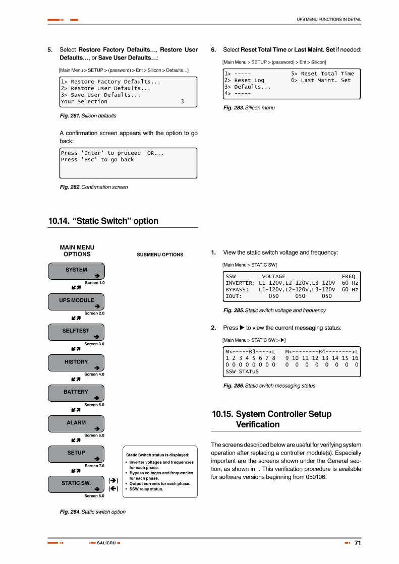
71
UPS MENU FUNCTIONS IN DETAIL
SALICRU
5. Select Restore Factory Defaults…, Restore User Defaults…, or Save User Defaults…:
[Main Menu > SETUP > (password) > Ent > Silicon > Defaults…]
1> Restore Factory Defaults...2> Restore User Defaults...3> Save User Defaults...Your Selection 3
Fig. 281. Silicon defaults
A confirmation screen appears with the option to go back:
Press 'Enter' to proceed OR...Press 'Esc' to go back
Fig. 282. Confirmation screen
6. Select Reset Total Time or Last Maint. Set if needed:
[Main Menu > SETUP > (password) > Ent > Silicon]
1> ----- 5> Reset Total Time2> Reset Log 6> Last Maint. Set3> Defaults...4> -----
Fig. 283. Silicon menu
10.14. “Static Switch” option
SYSTEM â
Screen 1.0
Screen 2.0
Screen 3.0
Screen 4.0
Screen 5.0
Screen 6.0
Screen 7.0
Screen 8.0
ç
ç
ç
ç
ç
ç
ç
UPS MODULE â
SELFTEST â
HISTORY â
BATTERY â
ALARM â
SETUP â
STATIC SW. â
(â)(á)
MAIN MENU OPTIONS SUBMENU OPTIONS
Static Switch status is displayed:
•Invertervoltagesandfrequenciesfor each phase.
•Bypassvoltagesandfrequenciesfor each phase.
•Outputcurrentsforeachphase.•SSWrelaystatus.
Fig. 284. Static switch option
1. View the static switch voltage and frequency:
[Main Menu > STATIC SW]
SSW VOLTAGE FREQINVERTER: L1-120V,L2-120V,L3-120V 60 HzBYPASS: L1-120V,L2-120V,L3-120V 60 HzIOUT: 050 050 050
Fig. 285. Static switch voltage and frequency
2. Press to view the current messaging status:
[Main Menu > STATIC SW > ]
M<-----B3---->L M<--------B4-------->L1 2 3 4 5 6 7 8 9 10 11 12 13 14 15 160 0 0 0 0 0 0 0 0 0 0 0 0 0 0 0SSW STATUS
Fig. 286. Static switch messaging status
10.15. System Controller Setup Verification
The screens described below are useful for verifying system operation after replacing a controller module(s). Especially important are the screens shown under the General sec-tion, as shown in . This verification procedure is available for software versions beginning from 050106.
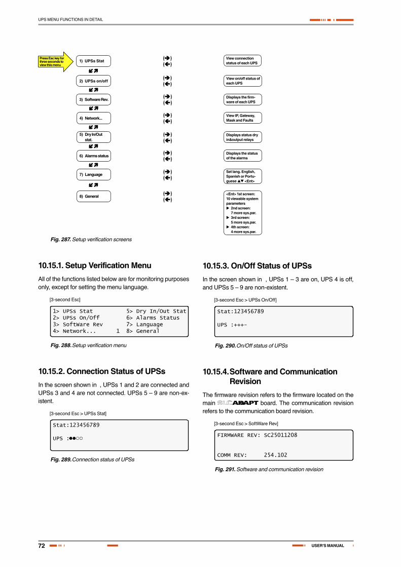
72
UPS MENU FUNCTIONS IN DETAIL
USER'S MANUAL
Press Esc key for three seconds to view this menu
ç
ç
ç
ç
ç
ç
ç
(â)(á)
(â)(á)
(â)(á)
(â)(á)
(â)(á)
(â)(á)
(â)(á)
(â)(á)
1) UPSs Stat
2) UPSs on/off
3) Software Rev.
4) Network...
5) Dry In/Out stat.
6) Alarms status
7) Language
8) General
View connection status of each UPS
View on/off status of each UPS
Displays the firm-ware of each UPS
View IP, Gateway, Mask and Faults
Displays status dry in&output relays
Displays the status of the alarms
Set lang. English, Spanish or Portu-guese <Ent>
<Ent> 1st screen:10 viewable system parameters 2nd screen: 7 more sys.par. 3rd screen: 5 more sys.par. 4th screen: 4 more sys.par.
Fig. 287. Setup verification screens
10.15.1. Setup Verification MenuAll of the functions listed below are for monitoring purposes only, except for setting the menu language.
[3-second Esc]
1> UPSs Stat 5> Dry In/Out Stat2> UPSs On/Off 6> Alarms Status3> SoftWare Rev 7> Language4> Network... 1 8> General
Fig. 288. Setup verification menu
10.15.2. Connection Status of UPSsIn the screen shown in , UPSs 1 and 2 are connected and UPSs 3 and 4 are not connected. UPSs 5 – 9 are non-ex-istent.
[3-second Esc > UPSs Stat]
Stat:123456789
UPS :
Fig. 289. Connection status of UPSs
10.15.3. On/Off Status of UPSsIn the screen shown in , UPSs 1 – 3 are on, UPS 4 is off, and UPSs 5 – 9 are non-existent.
[3-second Esc > UPSs On/Off]
Stat:123456789
UPS :+++-
Fig. 290. On/Off status of UPSs
10.15.4. Software and Communication Revision
The firmware revision refers to the firmware located on the main board. The communication revision refers to the communication board revision.
[3-second Esc > SoftWare Rev]
FIRMWARE REV: SC25011208
COMM REV: 254.102
Fig. 291. Software and communication revision

73
UPS MENU FUNCTIONS IN DETAIL
SALICRU
10.15.5. Network ParametersThe network parameters shown below define a specific
unit.
[3-second Esc > Network…]
IP 157.211.000.253Gateway: 157.211.000.251Mask: 255.255.255.000Faults: 090,073
Fig. 292. Network parameters
10.15.6. Dry Input and Output Relay Contact Status
The input and output contacts for the are displayed in : input relay contacts 1 and 3 are closed and all other contacts are open. The output contacts are generally used to provide external alarms.
[3-second Esc > Dry In/Out Stat]
Dry :12345678In :
Out :
Fig. 293. Dry input and output relay contact status
10.15.7. Alarms StatusAlarms shown as solid circles are active:
[3-second Esc > Alarms Status]
-------System Alarm Status--------1 32
Fig. 294. Alarms status
10.15.8. Setting the Menu LanguageSelect the desired menu language using the keys and press Ent:
[3-second Esc > Language]
----- LANGUAGE SETUP -----SELECT - 1: English (selected)SELECT - 2: SpanishSELECT - 3: Portuguese
Fig. 295. Set menu language
10.15.9. System Parameter SettingsUser the arrow keys to select General, and then press Ent.:
[3-second Esc]
1> UPSs Stat 5> Dry In/Out Stat2> UPSs On/Off 6> Alarms Status3> SoftWare Rev 7> Language4> Network... 1 8> General
Fig. 296. Select General
10.15.9.1. First General ScreenA description of the various system parameters shown in screen 1 are listed below.
[3-second Esc > GENERAL]
ACV:220...ALM:242/185 TEMP. ALARM:45CMODULES:07/02 C.LIM= off , T.C= 2.0mVDCV:432...ALM:475/360/340BATT...TEST:04/05/360/352...CAP: 0010 AH
Fig. 297. General (Screen 1)
a. ACV: nominal value of the input/output ac voltage (220 for 2x32 batteries; 110 for 2x16 batteries).
b. ALM: input ac voltage alarm HIGH/LOW.
c. TEMP. ALARM: high temperature limit for an ex-ternal temperature sensor.
d. MODULES: QUANTITY/REDUNDANCY: 07/02 in the screen means that 7 modules are presented in the system, 2 modules are reserve (full load is 10 kVA*(7-2)=50 kVA / 40 kW).
e. C.LIM.=off (VALUE): battery current limit function is de-activated (off) or maximum battery current value in Amps. If C.LIM is activated, the system must be equipped with an optional battery current sensor.
f. T.C. = 2.0mV: negative temperature coefficient of the battery dc voltage in mV per °C per battery cell. Nominal temperature is 25 °C. For dc nominal voltage 432 V , temperature 35 °C, 32 batteries of 6 cells, T.C.= 2 mV, the voltage is 432- 2*6*32*(35-25)~ = 428 V. NOTE. For most applications, T.C. must be 0 (off).
g. DCV: Dc nominal voltage for both positive and negative battery sets. For 32 batteries in the set DCV = 432 V, for 16 batteries 216 V.
h. DCV …ALM: Dc voltage alarms HIGH/LOW/SHUTDOWN. SHUTDOWN alarm is dc voltage value when the unit is stopped due to battery dis-charge.
i. BATT….TEST: PERIOD IN WEEKS/MAX.DURA-TION IN HOURS/ALARM VOLTAGE/CHARGER DERATED VOLTAGE. In the screen: the test is performed automatically once per 4 weeks, max.

74
UPS MENU FUNCTIONS IN DETAIL
USER'S MANUAL
test duration is 5 Hours, if battery voltage drops below 360 V alarm Battery Low is produced, and the chargers for the modules continue to supply a voltage of 352 V to prevent shutdown if battery is faulty.
j. CAP: CAPACITY in Amp-Hours. Used to calculate estimated back-up time of the system and battery test duration.
10.15.9.2. Second General ScreenFrom the screen shown in the previous section, press to view screen 2:
[3-second Esc > GENERAL > ]
CURRSHARE RST: DIS #OF PHASE: AUTOREV : SC25230909 LVD BY AC FAIL: DISMAINT: 2010.05.12 TEMP. SENSOR: DISSITE : 000001 CURR. SENSOR: DIS
Fig. 298. General (Screen 2)
A description of the various system parameters shown in screen 2 are listed below.
a. CURRSHARE RST: displays the status of the cur-rent sharing—either enabled or disabled (EN or DIS).
b. #OF PHASE: FORCE 3 for 3-phase output, FORCE 1 for single-phase output or AUTO when the mode is defined by DIP SWITCH of the mod-ules.
c. REV: revision of the system controller (SC) soft-ware.
d. LVD BY AC FAIL: DIS (disabled) or EN (enabled). This function, if enabled, performs system shut-down after 3 hours of ac failure to prevent deep battery discharge by low current. For most appli-cations, the function must be disabled.
e. MAINT: YEAR.MONTH.DAY: date of last mainte-nance.
f. TEMP. SENSOR: DIS or EN. External tempera-ture sensor is disabled/ enabled. In most applica-tions, it must be disabled.
g. SITE: the site identification number is used in net-work applications.
h. CURR.SENSOR: DIS or EN. Optional battery cur-rent sensor is disabled/ enabled. In most applica-tions, it must be disabled.
10.15.9.3. Third General ScreenFrom the screen shown in the previous section, press to view screen 3:
[3-second Esc > GENERAL > > ]
BOARD JUMPERS SETTING: 1. Not HARD Silicon 2. Silicon Mode 6. No Rmt Pan. 3. CAPACITY HI 9. AC: 220V
Fig. 299. General (Screen 3)
A description of the various system parameters shown in screen 3 are listed below:
a. Not HARD Silicon: Must be HARD only initially, during first activation of non-configured controller. After production, it should be Not HARD Silicon.
b. Silicon Mode: Regular mode allowing setup change. The setups are saved in an EEPROM chip.
c. CAPACITY HI (LO): High/low battery capacity mode when battery capacity is more/less than 100 Ah to achieve optimal resolution of the displayed value of battery current.
d. No/Yes Rmt Pan: Outputs of system controller are not configured or configured for an optional remote panel connection.
e. AC: 220 V: Nominal ac input voltage: 220 V for 2x32 batteries, 110 V for 2x16 batteries in series.
10.15.9.4. Fourth General ScreenFrom the screen shown in the previous section, press to view screen 4:
[3-second Esc > GENERAL > > > ]
SYSTEM OPERATION: STANDALONE MODEREMOTE COMMANDS: DISABLEBYPASS CONTROL: DISABLELINE FREQ./RANGE: AutoHz / 2Hz
Fig. 300. General (Screen 4)
A description of the various system parameters shown in screen 4 are listed below.
a. SYSTEM OPERATION: Indicates either stan-dalone or parallel mode.
b. REMOTE COMMANDS: These commands can be enable or disabled.
c. BYPASS CONTROL: This command can be ena-bled or disabled.
d. LINE FREQ./RANGE: The line frequency control and its variation range is indicated.
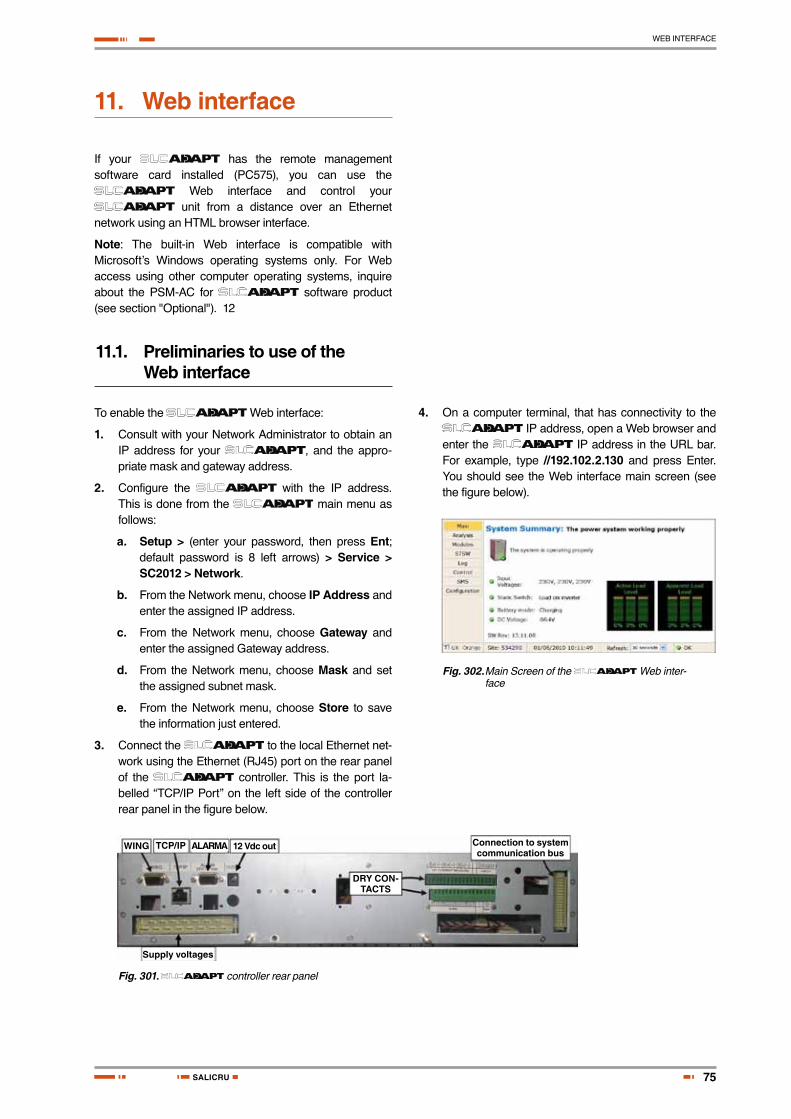
75
WEB INTERFACE
SALICRU
11. Web interface
If your has the remote management software card installed (PC575), you can use the
Web interface and control your unit from a distance over an Ethernet
network using an HTML browser interface.
Note: The built-in Web interface is compatible with Microsoft’s Windows operating systems only. For Web access using other computer operating systems, inquire about the PSM-AC for software product (see section "Optional"). 12
11.1. Preliminaries to use of the Web interface
To enable the Web interface:
1. Consult with your Network Administrator to obtain an IP address for your , and the appro-priate mask and gateway address.
2. Configure the with the IP address. This is done from the main menu as follows:
a. Setup > (enter your password, then press Ent; default password is 8 left arrows) > Service > SC2012 > Network.
b. From the Network menu, choose IP Address and enter the assigned IP address.
c. From the Network menu, choose Gateway and enter the assigned Gateway address.
d. From the Network menu, choose Mask and set the assigned subnet mask.
e. From the Network menu, choose Store to save the information just entered.
3. Connect the to the local Ethernet net-work using the Ethernet (RJ45) port on the rear panel of the controller. This is the port la-belled “TCP/IP Port” on the left side of the controller rear panel in the figure below.
WING
DRY CON-TACTS
Supply voltages
TCP/IP ALARMA 12 Vdc out Connection to system communication bus
Fig. 301. controller rear panel
4. On a computer terminal, that has connectivity to the IP address, open a Web browser and
enter the IP address in the URL bar. For example, type //192.102.2.130 and press Enter. You should see the Web interface main screen (see the figure below).
Fig. 302. Main Screen of the Web inter-face

76
WEB INTERFACE
USER'S MANUAL
11.2. Main Screen
The Main Screen (see above) is the first screen you see when connecting to the GMaCi software.
The column on the left side of the screen is the Main Menu. The first option in the Main Menu brings you to the Main Screen when you are not already there. The items in the rest of the Main Screen are described in .
ITEM DESCRIPTION
System Summary:
Informs you if attention is required or not.
GSM module status
Cellular (GSM) communication is Available / Not available. A signal-strength indicator is displayed along with the service provider name. Cellular communication requires the Wing module.
Site number: The site number is identified.
Date and time
The current date and time are displayed.
Refresh: The time interval at which the display is periodically updated.
ITEM DESCRIPTION
UPS image - No active alarms at this time.
One or more alarms are active.
Input voltages
The voltage of each input phase is listed.
All input voltages are within range.
One or more of the input phases has a voltage outside of the permitted range.
Static Switch Load on: Inverter (checkmark) / Bypass (“x”)
Load on inverter. Load on bypass.
Battery mode:
Charging (checkmark) / Discharging (“x”)
Battery charged or charging.
Battery discharging or discharged.
Dc voltage Current battery / charging voltage (Vdc).
Battery voltage in range.
Battery voltage out of range.
Table 13. Main Screen features
11.3. The Main Menu and its options
The Main Menu of built-in remote manage-ment software consists of a column of option buttons on the left side of the Main Screen (see ).
lists the options in the Main Menu column on the Main Screen, and describes each option briefly. Each option is described in greater detail in the subsequent sections.
MENU OPTION DESCRIPTION
Main Displays a condensed system status: Alarm status and basic readings.
Analysis Shows real-time readings for each input and output phase: voltage, current, kVA, kW, and power factor.
ModulesDisplays status of individual UPS modules, shows input and output ac voltages and currents, dc voltage, and active alarms if any.
STSWDisplays status of Static Switch, including inverter output voltages and frequency, bypass voltages and frequency, and active alarms if any.
Log Displays system log; data can be printed or exported to an Excel file.
Control
From this screen, the following system commands can be executed: Move load to bypass, move load to inverter, start battery test, abort battery test, LEDs test, shutdown, startup, restart, simulate load on battery condition, simulate battery status is low.
Use of this option is disabled by factory default. To enable (or disable), from the Power+ console main menu choose the following:(7) Setup > (8) Service > (5) Config > (8) Rem Command
SMSView received or sent SMS Messages in this screen from this screen (Wing module must be present). Click Available SMS commands to send an SMS message.
Config. Configure the settings of the remote management software.
Table 14. Main Menu options
The Main Menu options are described in more detail below.
11.3.1. “Analysis” main menu optionThe main menu’s “Analysis” option lists current values for voltage, current, apparent power (kVA), active power (kW), and power factor, for each input and output phase.
Fig. 303. Analysis of system input and output voltages and power
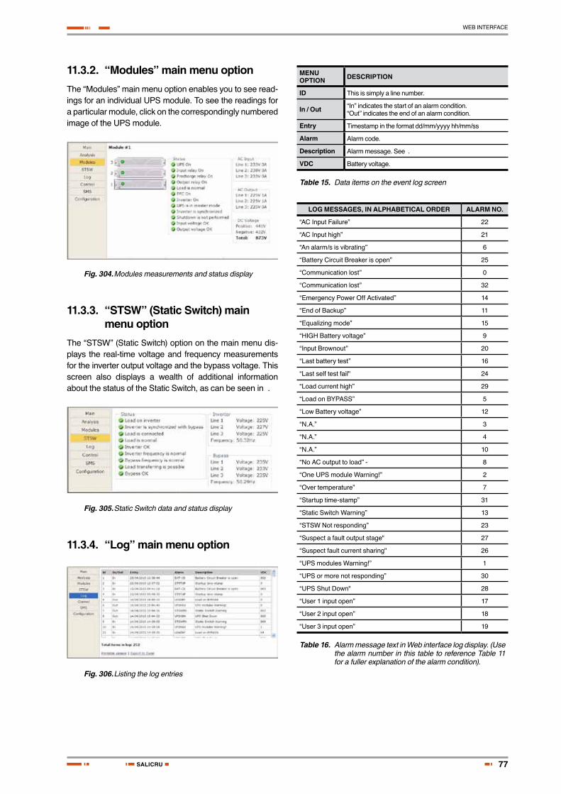
77
WEB INTERFACE
SALICRU
11.3.2. “Modules” main menu optionThe “Modules” main menu option enables you to see read-ings for an individual UPS module. To see the readings for a particular module, click on the correspondingly numbered image of the UPS module.
Fig. 304. Modules measurements and status display
11.3.3. “STSW” (Static Switch) main menu option
The “STSW” (Static Switch) option on the main menu dis-plays the real-time voltage and frequency measurements for the inverter output voltage and the bypass voltage. This screen also displays a wealth of additional information about the status of the Static Switch, as can be seen in .
Fig. 305. Static Switch data and status display
11.3.4. “Log” main menu option
Fig. 306. Listing the log entries
MENU OPTION DESCRIPTION
ID This is simply a line number.
In / Out “In” indicates the start of an alarm condition.“Out” indicates the end of an alarm condition.
Entry Timestamp in the format dd/mm/yyyy hh/mm/ss
Alarm Alarm code.
Description Alarm message. See .
VDC Battery voltage.
Table 15. Data items on the event log screen
LOG MESSAGES, IN ALPHABETICAL ORDER ALARM NO.
“AC Input Failure” 22
“AC Input high” 21
“An alarm/s is vibrating” 6
“Battery Circuit Breaker is open” 25
“Communication lost” 0
“Communication lost” 32
“Emergency Power Off Activated” 14
“End of Backup” 11
“Equalizing mode” 15
“HIGH Battery voltage” 9
“Input Brownout” 20
“Last battery test” 16
“Last self test fail" 24
“Load current high” 29
“Load on BYPASS” 5
“Low Battery voltage” 12
“N.A.” 3
“N.A.” 4
“N.A.” 10
“No AC output to load” - 8
“One UPS module Warning!” 2
“Over temperature” 7
“Startup time-stamp” 31
“Static Switch Warning” 13
“STSW Not responding” 23
“Suspect a fault output stage" 27
“Suspect fault current sharing" 26
“UPS modules Warning!” 1
“UPS or more not responding” 30
“UPS Shut Down" 28
“User 1 input open” 17
“User 2 input open” 18
“User 3 input open” 19
Table 16. Alarm message text in Web interface log display. (Use the alarm number in this table to reference Table 11 for a fuller explanation of the alarm condition).

78
WEB INTERFACE
USER'S MANUAL
11.3.5. “Control” main menu optionThe “Control” main menu option enables the user to initiate any of a number of UPS processes. The commands avail-able are described in below.
Fig. 307. The "Control" main menu option screen
MENU OP-TION
DESCRIPTION
Load on bypass Transfers the load to the bypass voltage.
Load on inverter Transfers the load to the inverter.
Start battery test
Initiates a battery test. Note: it is recommended that a battery test not be initiated when the when the UPS is operating near 100 % capacity and at the same time the battery is known to be not fully charged or not connected or otherwise faulty.
Abort battery test
Stop a battery test immediately.
LED test The UPS beeps briefly and all of the LEDs on the control panel light up, to reveal any faulty LEDs.
Shutdown Shuts down the UPS. Power will continue to be available to the loads from the bypass voltage.
Startup Starts up the UPS when it is in an “OFF” condition.
Restart When the UPS is “ON”, this command initiates a shutdown of the UPS followed by a startup.
Table 17. Commands available on the “Control” screen
At the bottom of the “Control” screen are two links:
• Simulate UPS output source on battery: clicking on this link simulates the conditions in effect during an ac power failure –a signal is sent via SNMP to any connected computers informing them of an ac power failure (in actuality, the load continues to be supplied from the inverter). If the computers are configured for automatic shutdown on ac power failure, they begin their shutdown countdown. This option is useful for testing the auto-shutdown configuration on a computer. The simulation can be ended by the user at will. If the countdown continues to completion, the designated shutdown targets (see section "Shutdown Targets") will be shut down!
• Simulate UPS battery status is low: clicking on this link simulates the conditions in effect after an extended ac power failure –a signal is sent via SNMP to any connected computers informing them of a “low battery condition” (actually non-existent). If the computers are configured for automatic shutdown on low battery, they begin their shutdown countdown. This option is
useful for testing the auto-shutdown configuration on a computer. The simulation can be ended by the user at will.
Warning: The low-battery countdown is config-ured in seconds, so computer shutdown will occur relatively quickly.
11.3.6. "SMS” main menu optionOn units equipped with the optional GSM cellular communications module, the “SMS” main menu option enables the controller to send an SMS message to any cellular telephone, and review all received or sent SMS messages. Messages are automatic; they cannot be cre-ated by the user.
Fig. 308. “SMS” screen
11.3.7. “Configuration” main menu option
Choosing the “Configuration” option on the Web interface’s main menu displays the Configuration (sub) menu. Through this menu, various important UPS settings can be modi-fied. The options in the Configuration menu are described below.
Fig. 309. Configuration menu
Selecting any of the options in the Configuration menu causes the Web interface to prompt for a user-ID and password. The factory default user-ID is admin, and the factory-default password is also admin. These default values for the user-ID and password can be changed, as is explained below in section "Set user name and password".

79
WEB INTERFACE
SALICRU
After entering the correct user-ID and password and then pressing Enter, the requested screen is displayed.
The user-ID and password are only requested once per session, on the first entry into any of the Configuration menu options.
Warning: When an IP address or addresses are specified for a given community, only the
specified addresses have access to the community. All other users will be shut out from the defined community.
11.3.7.1. Network configurationThe “Network configuration” option on the Configuration menu is equivalent to navigating to Setup > Service > SC2012 > Network on the physical con-trol panel. Here you define the parameters needed to com-municate with the over an intranet or over the Internet.
Consult your local network administrator for the proper IP address, subnet mask, and Gateway address.
Fig. 310. Configuring network communication param-eters
11.3.7.2. “Date and time” – setting the calendar and clock
The “Date and time” option on the Configuration submenu is used to set the date and time of the in-ternal calendar and clock. The date and time settings are important, for they are used to timestamp entries in the
log.
The date and time are kept current by the , including when the system is in the “off” state.
Click the Back button to return to the Configuration menu.
Fig. 311. Setting the UPS internal date and time
11.3.7.3. Set user name and passwordThe “Set user name and password” on the Configuration submenu enables you to change the user-ID and password used for entry into the options on the Web interface’s Con-figuration submenu.
The factory default user-ID and password are admin and admin. The new user-ID and password must each have a minimum of four characters and up to a maximum of nine characters. If entered, the new user-ID and password are effective immediately.
Click the Back button to return to the Configuration sub-menu.
Fig. 312. Changing username and password of the Web interface
11.3.7.4. SNMP securityThe SNMP security screen is where you define the SNMP communities that will have access to the , and whether that access will be “read only” (requests for data – a “read-only”) or “read-write” (includes the ability to modify G4 settings).
You also have the capability of limiting the IP addresses from which the G4 will accept SNMP packets. If the IP ad-dress has four segments of zero, this means that all users in the community will have the designated access.
Fig. 313. Define SNMP permissions
11.3.7.5. SNMP trap targetsAn SNMP trap is a destination to which the G4 will send alarm notifications using the SNMP protocol. For each des-tination, an IP address and a port must be specified.

80
WEB INTERFACE
USER'S MANUAL
Fig. 314. Defining SNMP trap targets
11.3.7.6. Shutdown TargetsThe “Shutdown Targets” option of the Configuration menu is where you record the IP address of the computers that you want to perform an orderly shutdown in the event of an ac mains power outage.
To use this option, the computer in question must have a Shutdown Agent installed on it. The Shutdown Agent is available from your vendor as a self-installing “setup.exe” file intended to be run on the target computer.
Note: The built-in Web interface supports a maximum of 15 shutdown targets. Customers requiring a larger number of shutdown targets should inquire about the PSM-AC for
software product (see section ).
Fig. 315. Define computers for auto-shutdown
FIELD DESCRIPTION
Address IP address of the computer to be automatically shut down in the event of a power failure.
Ac Fail delay (minutes)
Delay in minutes between ac failure and initiation of the automatic shutdown.
Low Battery delay (seconds)
Delay in seconds between low-battery alarm and initiation of the automatic shutdown.
Table 18. Defining computers for auto-shutdown
HOW AUTO-SHUTDOWN WORKS:
In the event of an ac power mains failure, the sends a notification to the IP addresses defined in the PC notification and shutdown screen. This generates a pop-up message on the computer screen advising of the ac fail condition, and starts a countdown. The countdown for each computer lasts for the number of minutes specified in the “Ac fail delay” field. If this countdown is exhausted before ac power returns, the Shutdown Agent saves and closes any open datasets on the computer and then shuts the com-puter down.
If during the countdown, the battery falls below a preset voltage (the low-battery voltage threshold, defined via the controller), the notifies the defined computers of the low-battery condition. This starts another countdown, that lasts for the number of seconds defined in the “Low bat-tery delay” field and also cancels any other active shutdown countdown. When this latest countdown is exhausted, the Shutdown Agent saves and closes any open datasets on the computer and then shuts the computer down. This takes place even if the “Ac fail delay” countdown was not yet finished.
11.3.7.7. Defining email notification targetsThe Web interface enables you to have notifications of system alarm conditions sent by email. To use this feature, the outgoing email server must be defined in the “E-mail no-tifications screen”, accessible from the Configuration menu.
Fig. 316. Defining email notification targets
FIELD DESCRIPTION
SMTP server address
DNS name or IP address of the outgoing email server. The Power+ must be defined to the email server as NOT requiring a login.
SMTP port Predefined SMTP port for the notification messages
Send as: The “from” address in the outgoing email. Note: some email servers have an anti-spam feature that requires the “from” address to be a valid, existing address.
Recipients In each line under the “Recipients” header, a single email address can be entered in standard format. For example: “[email protected]” (without the quotes). A single email address representing a list of addresses can also be entered.
Table 19. Fields in the email notifications screen

81
WEB INTERFACE
SALICRU
11.3.7.8. Defining SMS notificationsThe “SMS notifications” option of the configuration menu enables you to define telephone numbers that are to re-ceive notification via SMS in the event of specific alarm con-ditions on the .
Fig. 317. Defining SMS recipients
FIELD DESCRIPTION
Phone number
Specify the phone number to which the SMS notification will be sent. The notification includes an indication of the type of alarm.
Table 20. Fields in the SMS notification target definition screen

82
OPTIONAL
USER'S MANUAL
12. Optional
12.1. SNMP Agent
The SNMP agent is an optional, internal card which ena-bles the user to monitor and control the system from a PC. The SNMP agent enables monitoring, management, control, and orderly shutdown of the UPS via the Internet protocol SNMP. The SNMP agent provides connectivity between the UPS and external UPS manage-ment software such as the PSM-AC.
During normal operation, the SNMP agent transmits infor-mation about present operating conditions: for example, input and output voltage, current, and frequency. In the event of a power outage, the SNMP agent can perform an automatic, orderly shut down of a computer system before the batteries of the back-up power system (UPS) run out. The SNMP agent also provides real-time notification of UPS events in several modalities: for example, via email or SMS.
Use of an SNMP agent disables the RS232 interface of the UPS.
The SNMP agent is intended for use with a UPS man-agement software application such as PSM-AC, a sophisticated software suite for managing mul-tiple power supply and UPS systems. The systems can be controlled both locally and from a remote location.
Fig. 318. PSM-AC lets you monitor and control your UPS
12.2. Wing: Wireless Control
The system includes an option for wireless control and management, using the Wing.
The Wing allows real-time detection of power system faults and immediately notifies selected recipients (control center, technician, etc.) detailing the faults.
The Wing consists of:
• Wing board.
• SIM board.
• Antenna.
• D9-D9 cable (for RS232 between the and the Wing).
• Dc power cable (banana plugs on both ends).
UPS series
Wing
Fig. 319. A Wing unit connected to the
12.2.1. Installing the WingNote: The instructions in this section are for a Wing unit that has been ordered specifically for use with a system. If your Wing was ordered for use with another type of system, it does not contain the appropriate software for use with a system and you should contact your vendor if you wish to convert it for use.
To install a Wing unit for use with a system:
1. Take the Wing and press the button on the left side of the SIM slot to unlock the SIM cardholder; remove the SIM cardholder from the Wing.
2. Place your SIM card (which you obtained from your cellular service provider) in the SIM cardholder and slide the SIM cardholder gently and firmly back into the Wing.

83
OPTIONAL
SALICRU
3. Attach the supplied cellular antenna to the Wing.
4. Connect the Wing to the D9 socket labeled "Wing" on the left rear side of the controller using the supplied D9-D9 cable.
Left side of UPS controller rear panel Wing rear panel
Fig. 320. Connections between the con-troller and the Wing
5. Connect the supplied power cable between the 12 Vdc socket on the left side of the controller rear panel and the Wing.
6. On a computer that is connected to the same network as the , open a web browser, type the IP address of the into the URL bar, and press Enter.
The home page of the web interface is displayed.
(If you do not know the 's IP address, you can see it by pressing and holding the Esc button for 2 or 3 seconds and then choosing "Network" on the displayed menu).
Verify that an antenna symbol resembling a trident ap-pears in the lower left corner of the browser window. This indicates that the Wing has a cellular connection.
Fig. 321. Home screen of the web inter-face
7. From the Wing home page, navigate to Configuration > SMS notifications.
8. Enter the telephone numbers to which you want to have alarm notifications sent.
9. Commands and queries can be sent to the Wing from any cellular telephone.
To see a log of the incoming and outgoing SMS mes-sages, choose SMS in the menu column at the left side of the web page.
To see a list of the available SMS commands, on the SMS screen select the "Available SMS commands" link at the bottom of the SMS notifications screen. The available SMS commands are also listed here in con-tinuation.
Fig. 322. The SMS screen on the web interface
Command Description
? Commands are:?HelpAlarmsStatusTargetPassReboot
Help Commands are:?HelpAlarmsStatusTargetPassReboot
Alarms Get all active alarms
Status Get the system real time values
Target USAGE:target (index) (phone) (---) (password)Example:sms 1 +7123456789 admin
Pass USAGE:pass (new password) (old password)Example:pass abcd admin
Reboot Restart the system and network controllerUSAGE:reboot (password) Example:reboot admin
Table 21. List of SMS commands

84
RELATED PRODUCTS
USER'S MANUAL
13. Related Products
13.1. G4
Fig. 323. GMaCi G4
The G4 adds value to your :
• Option to connect external temperatures sensors.
• Input dry contacts available for on/off external sensors.
• Output dry contacts for control of external devices.
• Supports TCP/IP and SNMPv2.
• Controlled shutdown of servers on ac mains power failure, with user-defined time-delay. (*)
• Auto-wake-up of servers on restoration of ac power, after user-defined time-delay. (*),(**)
• Include internal GSM modem (quad-band) for an additional remote control and management link without LAN dependency.
• Bi-directional control via simple SMS commands.
• Automatic response to sensed events. For example, the G4 can be programmed to turn on an air conditioner when it senses that the room temperature has exceeded a user-defined level.
• Notifies designated targets of alarm conditions via email, SMS, and SNMP traps.
• Quick installation.
(*) Not all operating systems supported.
(**) Auto-wake-up requires "wake-on-LAN" BIOS feature on target computers. Not all operating systems supported.
Note: G4 requires disconnection of the in-ternal network card. Consult your vendor before ordering.
13.2. G-Eye
Fig. 324. G-Eye
G-Eye adds value to your :
• Option to connect external temperatures sensors, humidity sensors, and frequency sensors.
• Inputs for ac/dc current and voltage measurements through various sensors.
• When the measured value moves outside a user-defined range, G-Eye immediately informs pre-selected targets of the alarm condition.
• One 4-20 mA input.
• Input dry contacts available for on/off external sensors.
• Output dry contacts for control of external devices.
• Supports TCP/IP and SNMPv2.
• Controlled shutdown of servers on ac mains power failure, with user-defined time-delay. (*)
• Auto-wake-up of servers on restoration of ac power, after user-defined time-delay. (*), (**)
• Include internal GSM modem (quad-band) for additional backup/control/management without LAN dependency.
• Bi-directional control via simple SMS commands.
• Automatic response to sensed events. For example, the G4 can be programmed to turn on an air conditioner when it senses that the room temperature has exceeded a user-defined level.
• Notifies designated targets of alarm conditions via email, SMS, and SNMP traps.
• Double power feed for reliability.
• Internal battery backup.
• Quick installation.
(*) Not all operating systems supported.
(**) Auto-wake-up requires "wake-on_LAN" BIOS feature on target computers. Not all operating systems supported.
Note: G-Eye requires disconnection of the internal network card. Consult your vendor before ordering
.

85
MAINTENANCE, WARRANTY AND SERVICE
SALICRU
14. Maintenance, warranty and service
14.1. Warranty conditions
The limited warranty only applies to those products that you acquire for commercial or industrial use in the normal devel-opment of your business.
14.1.1. Covered product UPS series.
14.1.2. Warranty termsOur company guarantees this product against any parts and/or labour defect for 12 months period from its com-missioning by our personal staff or other specifically au-thorised, or 18 months from its factory delivery, whichever expires first. In case of failure of the product inside the war-ranty period, repairs to our facilities at no cost, the faulty part or parts. The transport expenses and packaging will be borne to the user.
Guarantee for period time higher than 10 years, the avail-ability of parts and spare parts, as hardware as software, as well as a complete assistance regarding the reparations, components replacement and software updating.
14.1.3. Out of the scope of supplyOur company is not forced by the warranty if it appreciates that the defect in the product doesn’t exist or it was caused by a wrong use, negligence, installation and/or inadequate testing, tentative of repairing or not authorized modification, or any other cause beyond the foreseen use, or by acci-dent, fire, lightnings or other dangers. Neither it will cover, in any case, compensations for damages or injuries.
14.2. Available maintenance and service contracts
When the warranty is expired, has several maintenance modalities:
• Preventive. It guarantees a higher safety to preserve the correct operating of the equipments with a yearly preventive visit, in which the specialised technicians make several tests and sets in the systems:
� Check and write down the input and output voltages and currents per phase.
� Check the logged alarms.
� Check the readings of the LCD panel.
� Other measurements.
� Check the fan status.
� Check the load level.
� Check the selected language.
� Check the correct location of the equipment.
General cleaning of the equipment.
This way, it is guaranteed the perfect operating and the possible coming faults are avoided.
These supervisions are usually done without shut-down the equipment. In those cases that a shut-down were needed, a date and time would agree with the customer to do the task.
This maintenance modality covers, inside the working timetable, all the journey expenses and manpower.
• Corrective. When a fault occurs in the equipment oper-ating, and previous notice to our Service and Technical Support (S.T.S.), in which a specialized technician will establish the failure scope and he will determine a first diagnostic, the corrective action starts.
The needed visits for its correct resolution are unlimited and they are included inside the maintenance modali-ties. This means that our technicians reviewed, in case of failure, will check the equipments as many time as it were needed.
Besides, inside these two modalities, is possible to fix the action timetable and response times in order to be adapted to the customer’s needs:
� LV8HLS. Customer’s attention from Monday to Friday from 9 h. to 18 h. Response time inside the same day or, as maximum, in the next 24 hours of the fault notification.
� LS14HLS. Customer’s attention from Monday to Saturday from 6 h. to 20 h. Response time is inside the same day or, as maximum, at first time of the next working day.
� LD24HLS. Customer’s attention from Monday to Sunday 24 h., 365 days per year. Response time in less than two or three hours after the fault notifica-tion.

86
MAINTENANCE, WARRANTY AND SERVICE
USER'S MANUAL
• Additional arrangement: 1-m-cb.
� Index 1. It means the number or Preventive visits per year. It includes displacement and manpower expenses inside the established timetable for each maintenance modality, as well as all the needed Correctives visits. Excluding all the parts and bat-teries in case of reparation.
� Index m. It means to include all the parts.
� Index cb. It means to include the batteries.
14.3. Technical service network
The covering, as national as international, of Service and Technical Support (S.T.S.) points, are made up by:
In Spain:
Andorra, Barcelona, Madrid, Bilbao, Gijon, A Coruña, Las Palmas de G.Canaria, Malaga, Murcia, Palma de Mallorca, San Sebastian, Santa Cruz de Tenerife, Seville, Taco (La Laguna - Tenerife), Valencia and Zaragoza.
At international level:
France, Brazil, Hungary, Portugal, Singapore, U.K., China, Mexico, Uruguay, Chile, Venezuela, Colombia, Argentina, Poland, Philippines, Malaysia, Pakistan, Morocco, Thai-land, United Arab Emirates, Egypt, Australia and New Zea-land.

87
GENERAL CHARACTERISTICS
SALICRU
15. General Characteristics
TECHNICAL DATA
Topology On line Battery, Double Conversion, VFI
Construction Modular parallel hot-plugged modules
Operation Continuous
Input
Voltage 3 × 400 Vac + N (3 x 230 Vac + Neutral)
Voltage range – 27 % and + 20 %
Current 3 × 15 A per module – no inrush current at startup
Frequency 47 Hz – 63 Hz
Power walk-in > 60 sec.
Power Factor 0.99
THDI 5 %
Output
Rated Power 10 kVA / 8 kW ÷ 100 kVA / 80 kW
Frequency (in free-running mode)
50/60 Hz ± 0,1%
Freq. tracking range ± 1 Hz, ± 2 Hz, ± 3 Hz (selectable)
Slew rate 1 Hz/sec.
Voltage 3 × 400 Vac + N (3 x 230 Vac + Neutral)
Static Regulation ± 1%
Regulation for unbalanced load
± 1% for 100% unbalanced load
Dynamic response to 100% load step
± 2%
Overload 110% for 10 min., 125% for 60 sec., 1000% for 1 cycle
Waveform Sinusoidal
THD Less than 2% for lineal load
Load CF (max.) 6:1
AC-AC efficiency (nom.) Up to 96% at full load
DC-AC efficiency (nom.) Up to 98% at full load
Batteries
DC-Link voltage (V) ± 340 a ± 425 Vdc
Quantity 64 x 12 Vdc
Type Sealed, lead acid, rechargeable
General
Maximum power dissipation (Po=8 kW)
N*333 W (N*1136 BTU), N = # modules
Ambient temperature: Operating: Storage:
-10 ÷ +40 ºC -20 ÷ +60 ºC
Relative humidity Up to 95%, non-condensing
Acoustic noise 48 ÷ 58 dBA with the 50% of the load51 ÷ 61 dBA full load
Altitude 1500 m. without derating
Enclosure IP20
Cooling system Multi-fan with speed control (forced)
TECHNICAL DATA
Standards
EMC EN50091-2 Class A; IEC 62040-2 Class A
Design EN50091-3; IEC 62040-3
Safety EN50091-1; IEC 62040-1-1
Low magnetic field radiation
EMF as per ICNIRP
Table 22. Specifications
SYSTEM CONTROLLER – TECHNICAL DATA
Micro Controller core 16 bit
Display 4 × 40 characters LCD with backlight
Other indicators 8 LEDs, buzzer
Analog input channels 4
Digital input channels 8
Real Time Clock (RTC) Yes, with backup
Power meter kVA, kW, PF
Volt-free outputs (dry contacts) 6 outputs, rated 50 Vdc / 1 A
RS232 user port Yes, isolated
Optional communication TCP/IP, GPRS/SMS Wireless communications(Optional)
Communications with system modules
Serial, isolated
Events log 255 events
System operation without controller
Unchanged
On-screen parameters - Load bar-graph- 3-phase voltages- 3-phase currents- Battery voltage- Status of each UPS module- Static-switch parameters and
status- Battery sensor temperature
Alarms - AC failure- DC failure- UPS module(s) failure- Load on bypass- Battery test failure- Over/under temperature- Overload(Contacts rated max. 48 Vdc 1 A)
RTC operation without power 2 weeks
Power requirements 3 × 400 Vac / ± 425 Vdc 15 W
Table 23. Control system specifications
All specifications are subject to change without notice.

Avda. de la Serra, 10008460 PalautorderaBARCELONATel. +34 93 848 24 00
902 48 24 00Fax. +34 94 848 11 [email protected]. (S.T.S.) 902 48 24 01Fax. (S.T.S.) +34 848 22 [email protected]
MADRIDBARCELONABILBAOGIJÓNLA CORUÑALAS PALMAS DE G. CANARIAMÁLAGA
MURCIAPALMA DE MALLORCAPAMPLONASAN SEBASTIANSEVILLAVALENCIAVALLADOLIDZARAGOZA
BRANCHES AND SERVICES and TECHNICAL SUPPORT (S.T.S.....)
FRANCEPORTUGALHUNGARYUNITED KINGDOM
CHINASINGAPOREMEXICO
SUBSIDIARIES
GERMANYBELGIUMDENMARKHOLLANDIRELANDNORWAYPOLANDCZECH REPUBLICRUSSIASWEDENSWITZERLANDUKRAINEARGENTINABRAZILCHILECOLOMBIACUBAECUADOR
PERUURUGUAYVENEZUELASAUDI ARABIAALGERIAEGYPTJORDANKUWAITMOROCCOTUNISIAKAZAKHSTANPAKISTANUEAPHILIPPINESINDONESIAMALAYSIATHAILANDVIETNAM
REST of WORLD
Product Range
Uninterruptible Power Supply UPS
Lighting Flow Dimmer-Stabilizers
Power Supplies
Static Inverters
Photovoltaic Inverters
Microturbines
Voltage Stabilisers
Not
a: S
alic
ru c
an g
ive o
ther
ele
ctro
nics
sol
utio
ns a
ccor
ding
to th
e ap
plic
atio
n sp
ecifi
catio
ns o
r tec
hnic
al sp
ecifi
catio
ns.
U N I N T E R R U P T I B L E P O W E R S U P P LY ( U P S ) + L I G H T I N G F L O W D I M M E R S TA B I L I Z E R S + P O W E R S U P P LY + S TAT I C I N V E R T E R S + P H O T O V O LTA I C I N V E R T E R S + M I C R O T U R B I N E S + V O LTA G E S TA B I L I S E R S
EK903A01