unit 2: - ecollege€¦ · web viewunit: 5. tungsten active gas shielded welding (tags/tig)...
TRANSCRIPT
TRADE OFPipefitting
PHASE 2
Module 2
Thermal Processes
UNIT: 5
Tungsten Active Gas Shielded Welding
(TAGS/TIG)
Produced by
In cooperation with subject matter expert:
Finbar Smith
© SOLAS 2014
Tungsten Active Gas Shielded Welding (TAGS/TIG)
Revision 2.0 September 2014
Module 2– Unit 5
Table of ContentsUnit Objective......................................................................1Learning Outcome...............................................................21.0 TAGS Welding for Pipefitting....................................3
1.1 Introduction to Tungsten Arc Gas Shielded (TAGS) Welding.....................................................................3
1.2 Tungsten Arc Gas Shielded (TAGS) Welding Process 41.3 Initiating the Arc.......................................................51.4 Pulsed TAGS Welding...............................................51.5 Advantages and Disadvantages of (TAGS) Welding. 5
2.0 Identifying TAGS Equipment....................................72.1 Power Sources for TAGS Welding............................72.2 Types of TAGS Welding Plant...................................72.3 AC Composite Power Source....................................82.4 DC Composite Power Source....................................92.4 AC / DC Composite Power Source............................92.5 Torches for TAGS Welding
..................................................................................10
2.6 Regulator and Gas Flow Meters..................................................................................11
2.7 Shielding Gases Used for TAGS Welding..................................................................................12
3.0 Hazards and Safety Precautions Associated with TAGS Welding..................................................................................13
3.1 Safety Precaution for TAGS Welding..................................................................................13
4.0 Electrodes for TAGS Welding..................................................................................14
4.1 Electrodes for TAGS Welding..................................................................................14
4.2 Filler Wire for TAGS Welding..................................................................................15
5.0 Set Up TAGS Welding Equipment..................................................................................16
5.1 Generic Set-Up Procedure for TAGS Welding..................................................................................16
Industrial Insulation Phase 2
Tungsten Active Gas Shielded Welding (TAGS/TIG)
Revision 2.0 September 2014
Module 2– Unit 5
5.2 Preparation of Material Prior to Welding..................................................................................17
5.3 Procedure for TAGS Welding Technique..................................................................................18
5.4 Procedure for TAGS Welding Stainless Steel..................................................................................18
5.4 Procedure for TAGS Welding Aluminium..................................................................................20
Exercises..................................................................................21
Additional Resources..................................................................................21
Industrial Insulation Phase 2
Tungsten Active Gas Shielded Welding (TAGS/TIG)
Revision 2.0 September 2014
Module 2– Unit 5
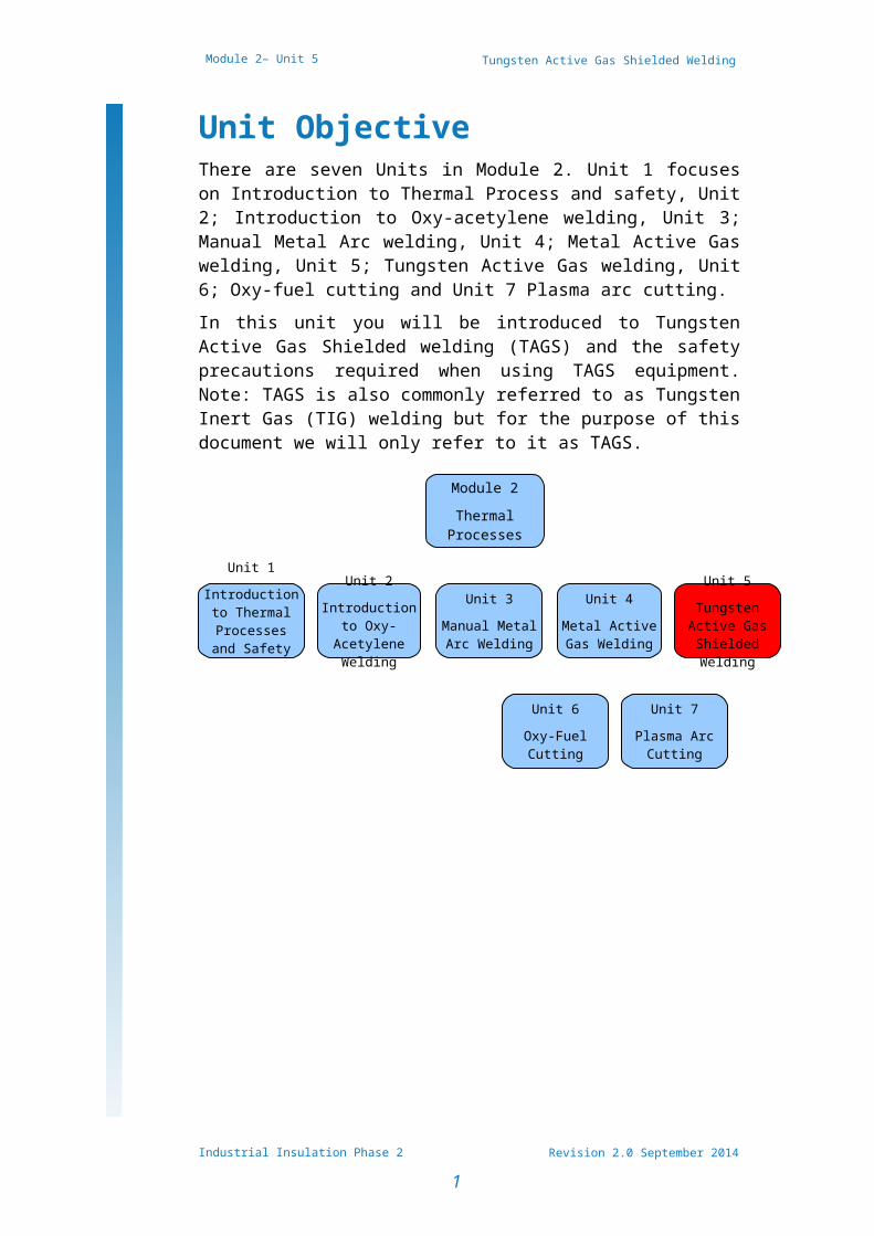
Unit ObjectiveThere are seven Units in Module 2. Unit 1 focuses on Introduction to Thermal Process and safety, Unit 2; Introduction to Oxy-acetylene welding, Unit 3; Manual Metal Arc welding, Unit 4; Metal Active Gas welding, Unit 5; Tungsten Active Gas welding, Unit 6; Oxy-fuel cutting and Unit 7 Plasma arc cutting.In this unit you will be introduced to Tungsten Active Gas Shielded welding (TAGS) and the safety precautions required when using TAGS equipment. Note: TAGS is also commonly referred to as Tungsten Inert Gas (TIG) welding but for the purpose of this document we will only refer to it as TAGS.
Industrial Insulation Phase 2
1
Module 2Thermal
Processes
Unit 1
Introduction to Thermal
Processes and Safety
Unit 2
Introduction to Oxy-
Acetylene Welding
Unit 3
Manual Metal Arc Welding
Unit 5
Tungsten Active Gas Shielded Welding
Unit 4
Metal Active Gas Welding
Unit 6
Oxy-Fuel Cutting
Unit 7
Plasma Arc Cutting
Tungsten Active Gas Shielded Welding (TAGS/TIG)
Revision 2.0 September 2014
Module 2– Unit 5
Learning OutcomeBy the end of this unit each apprentice will be able to:
Describe the Tungsten Active Gas Shielded (TAGS/TIG) welding process and applications for pipe fitting
Identify TAGS/TIG welding power source, shielding gases and ancillary equipment
State the safety precautions and PPE required when using TAGS/TIG welding Equipment
Select suitable filler wire for the TAGS/TIG welding process
Set up TAGS welding equipment and adjust welding parameters to produce sample weld beads
Describe the effects of heat on metal during welding and describe methods to control distortion
Industrial Insulation Phase 2
2
Tungsten Active Gas Shielded Welding (TAGS/TIG)
Revision 2.0 September 2014
Module 2– Unit 5
1.0TAGS Welding for Pipefitting
Key Learning Points Identify the origin of the TAGS/TIG welding process Identify how the TIG welding process works Identify the advantages and disadvantages of TAGS
welding process
1.1 Introduction to Tungsten Arc Gas Shielded (TAGS) Welding
Welding of aluminium and magnesium had always been a problem with conventional manual metal arc and oxyacetylene processes. Corrosive fluxes had to be used to remove the oxide film from the material surface and molten pool.To overcome this problem, and to eliminate atmospheric contamination during welding, inert gas was first employed as a shield in the early 1930s.The first gas-shielded process used a tungsten electrode and helium shielding gas. It was called the tungsten inert gas (TIG) process. Direct current with electrode positive was used. With this system, the tungsten electrode tended to overheat and transfer fragments of tungsten to the weld unless a low current was utilised.It was found that overheating could be avoided by making the tungsten electrode negative. This made the process suitable for welding stainless steel but unsuitable for aluminium and magnesium.The development that allowed these materials to be welded was the use of alternating current, with a high-frequency, high-voltage current superimposed over the basic welding current to stabilise the arc. Using a.c. gives the perfect answer for welding aluminium and magnesium. When the electrode is positive, a cleaning action takes place on the surface of the weld and plate area; particles of oxide are lifted up electrically, leaving an oxide-free area. On the next half-cycle, the electrode becomes negative, allowing it to cool slightly and preventing overheating. As the cycle repeats, the alternating current gives the perfect balance of oxide removal and electrode cooling; the inert gas shield prevents further contamination until the molten pool has solidified.
Industrial Insulation Phase 2
3
Tungsten Active Gas Shielded Welding (TAGS/TIG)
Revision 2.0 September 2014
Module 2– Unit 5
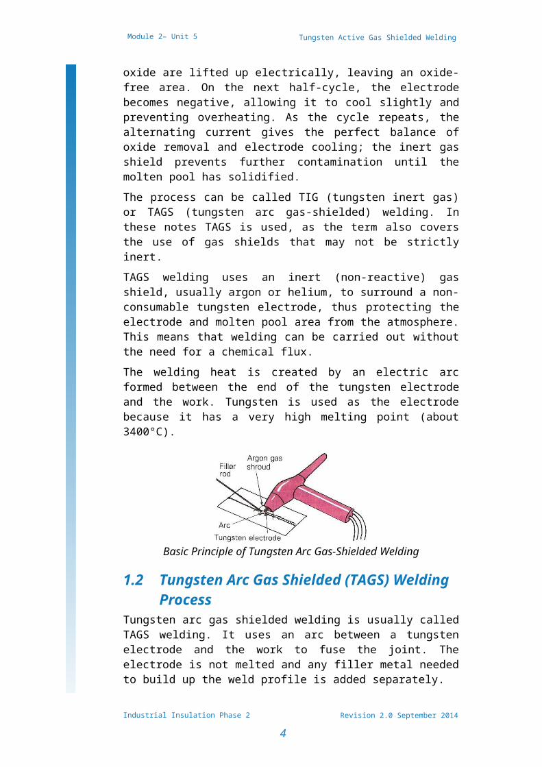
The process can be called TIG (tungsten inert gas) or TAGS (tungsten arc gas-shielded) welding. In these notes TAGS is used, as the term also covers the use of gas shields that may not be strictly inert.TAGS welding uses an inert (non-reactive) gas shield, usually argon or helium, to surround a non-consumable tungsten electrode, thus protecting the electrode and molten pool area from the atmosphere. This means that welding can be carried out without the need for a chemical flux.The welding heat is created by an electric arc formed between the end of the tungsten electrode and the work. Tungsten is used as the electrode because it has a very high melting point (about 3400°C).
Basic Principle of Tungsten Arc Gas-Shielded Welding
1.2 Tungsten Arc Gas Shielded (TAGS) Welding Process
Tungsten arc gas shielded welding is usually called TAGS welding. It uses an arc between a tungsten electrode and the work to fuse the joint. The electrode is not melted and any filler metal needed to build up the weld profile is added separately.Both the molten metal in the weld pool, the tip of the filler wire and the hot electrode are protected from atmospheric contamination by a shield of inert gas. Usually the gas is argon, but helium by itself or mixed with argon may be used for special applications. Argon - hydrogen mixtures can be used for stainless steel.TAGS welding is suitable for both manual and automatic welding.In manual welding, the operator points the electrode in the direction of welding and uses the arc to melt the metal at the joint.If filler metal is required, for example when making a fillet weld, it is added to the leading edge of the weld pool.
Industrial Insulation Phase 2
4
Tungsten Active Gas Shielded Welding (TAGS/TIG)
Revision 2.0 September 2014
Module 2– Unit 5
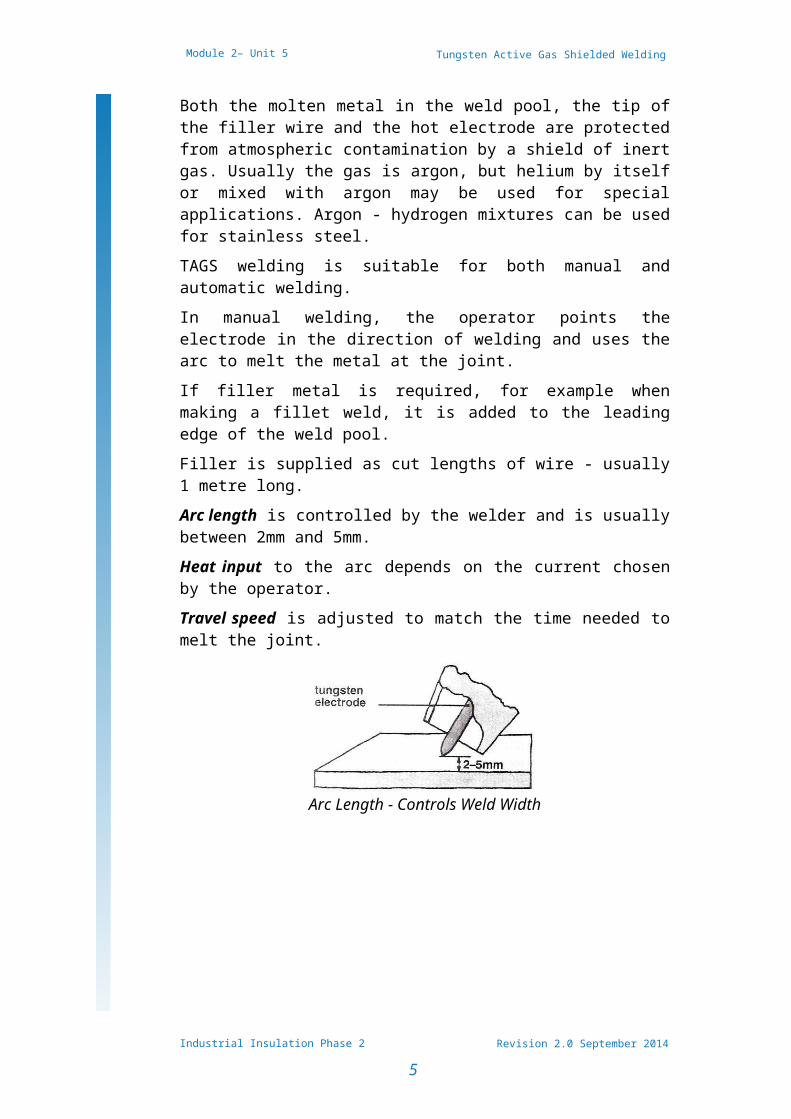
Filler is supplied as cut lengths of wire - usually 1 metre long.Arc length is controlled by the welder and is usually between 2mm and 5mm.Heat input to the arc depends on the current chosen by the operator.Travel speed is adjusted to match the time needed to melt the joint.
Arc Length - Controls Weld Width
Industrial Insulation Phase 2
5
Tungsten Active Gas Shielded Welding (TAGS/TIG)
Revision 2.0 September 2014
Module 2– Unit 5
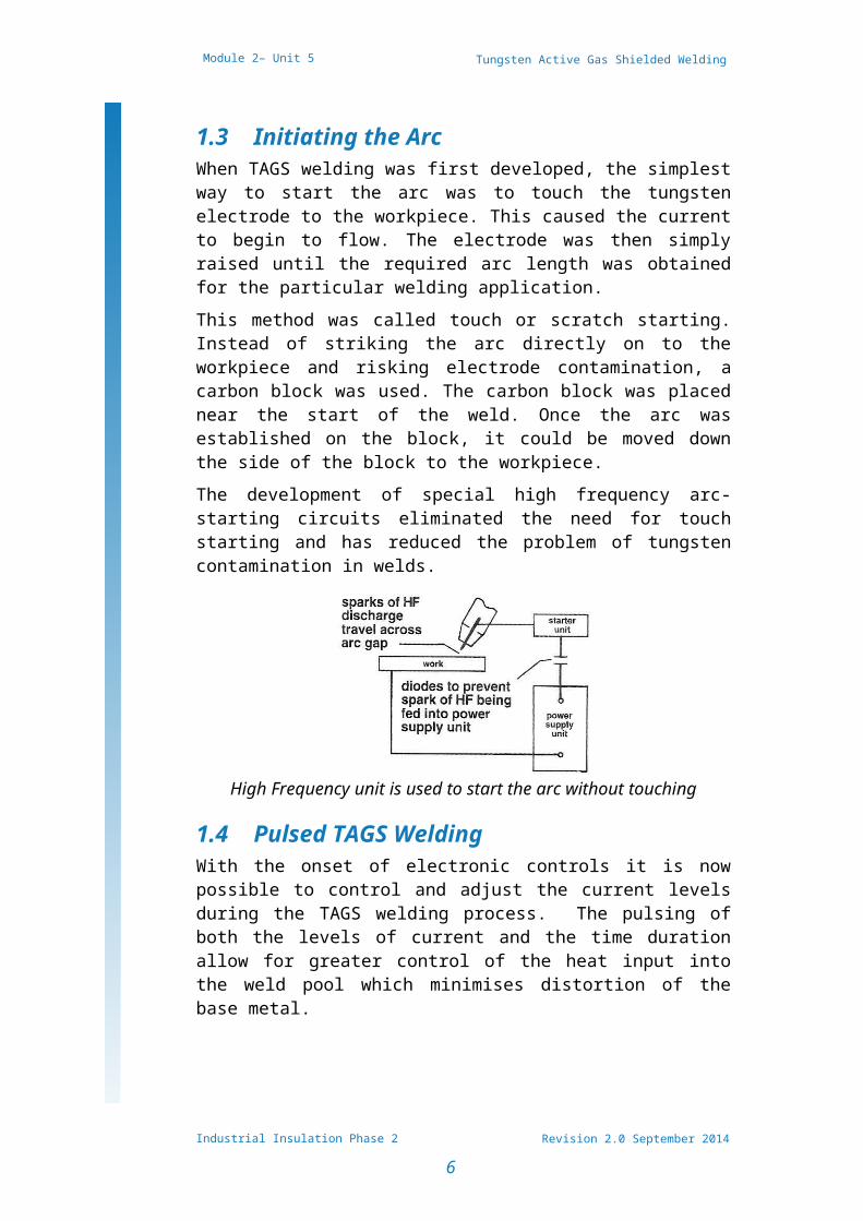
1.3 Initiating the ArcWhen TAGS welding was first developed, the simplest way to start the arc was to touch the tungsten electrode to the workpiece. This caused the current to begin to flow. The electrode was then simply raised until the required arc length was obtained for the particular welding application.This method was called touch or scratch starting. Instead of striking the arc directly on to the workpiece and risking electrode contamination, a carbon block was used. The carbon block was placed near the start of the weld. Once the arc was established on the block, it could be moved down the side of the block to the workpiece.The development of special high frequency arc-starting circuits eliminated the need for touch starting and has reduced the problem of tungsten contamination in welds.
High Frequency unit is used to start the arc without touching
1.4 Pulsed TAGS WeldingWith the onset of electronic controls it is now possible to control and adjust the current levels during the TAGS welding process. The pulsing of both the levels of current and the time duration allow for greater control of the heat input into the weld pool which minimises distortion of the base metal.
1.5 Advantages and Disadvantages of (TAGS) Welding
Tungsten arc gas shielded welding has the following advantages:
Fine control over welding parameters - travel speed, heat of weld pool, depth of weld, amount of filler metal gives superior welds.
No splatter
Industrial Insulation Phase 2
6
Tungsten Active Gas Shielded Welding (TAGS/TIG)
Revision 2.0 September 2014
Module 2– Unit 5
Minimum heat input therefore minimum distortion of the base material
Most weldable metals can be welded by the TAGS welding process.
Stainless steels are often TAGS welded because of the cleanliness of the process and quality of results, especially for food or pharmaceutical applications.
The TAGS welding process is well suited to automatic and orbital welding as good results are repeatable.
TAGS is one of the cleanest, most precise welding procedures available. The operator has complete control over all welding variables and can change most during the welding process with no need to stop the weld. TAGS does have a few disadvantages,
Slower than most other weld procedures Operator must be very close to weld in progress Equipment is more expensive and complex than for
other welding procedures TAGS welding is more demanding and requires more
operator skill.
Industrial Insulation Phase 2
7
Tungsten Active Gas Shielded Welding (TAGS/TIG)
Revision 2.0 September 2014
Module 2– Unit 5
2.0Identifying TAGS Equipment
Key Learning Points Identify equipment used for TAGS welding Differentiate the different types of power sources
used for TAGS welding Identify gases used for TAGS welding and their
applications
2.1 Power Sources for TAGS WeldingPower sources for use with TAGS welding must be capable of delivering a constant current at a preset value. They are often called 'drooping characteristic' units.Rectifier units are commonly used for dc welding although motor generators may be more suitable for site work.Single phase transformer units are almost universally used for welding aluminium. Modern power sources have square waveform.Combined ac/dc power sources can be used where there is a mix of work.Modern power sources combine constant current and constant voltage (cc/cv) and are called inverters.The power source should be equipped with:
foot operated on/off switch remote control for the current crater filling device an arc starting device gas control valves water control valves - for nozzle cooling at high cur-
rents.
2.2 Types of TAGS Welding PlantThere are 2 types of TAGS welding plant which are classified in accordance with their output current; direct current (DC) and alternating current (AC). Sizes vary from 3 to 400 amperes output.
Industrial Insulation Phase 2
8
Tungsten Active Gas Shielded Welding (TAGS/TIG)
Revision 2.0 September 2014
Module 2– Unit 5
Direct current with the electrode connected to the negative terminal of the power source is used for:
carbon steels copper and its alloys stainless steels nickel and its alloys titanium and its alloys zirconium and its alloys
Alternating current is used for welding: aluminium and its alloys magnesium and its alloys aluminium bronze
2.3 AC Composite Power SourceUsually single-phase transformers, either air or oil cooled.The built-in auxiliaries usually include:1. Remote-controlled contactor to enable the operator to
switch the welding current on or off.2. Capacitors to suppress the D.C. component produced in
the welding circuit.3. A high-frequency unit or a combined h.f. and voltage
surge injector to initiate and maintain the arc.4. Solenoids to control gas and water flows. 5. In many cases a switch is provided to enable the power
source to be used for manual metal-arc welding.6. New models with electronic circuitry can now be the
size of a briefcase.
2.4 DC Composite Power SourceIndustrial Insulation Phase 2
9
Tungsten Active Gas Shielded Welding (TAGS/TIG)
Revision 2.0 September 2014
Module 2– Unit 5
Usually three-phased rectifier units comprising:1. Transformer.2. Rectifier bank.3. Remote-controlled contactor.4. Spark starter to initiate the arc.5. Solenoids to control gas and water supplies.6. Sometimes, remote control of welding current.In many cases a switch is provided to enable the power source to be used for manual metal-arc welding with D.C.
2.4 AC / DC Composite Power SourceSingle-phase transformer rectifiers can provide either an A.C. or D.C. output as required.These power sources usually include automatic high-frequency sources for both A.C. and D.C. welding, together with the usual auxiliaries.(In many cases a switch is provided to enable the power source to be used for manual metal-arc welding with A.C. or D.C.).Note: Power sources used for manual metal-arc welding can be adapted for this process if additional features are added to the circuit.It is better to use a composite power source specially designed for tungsten-arc gas shielded welding, that can be switched subsequently for use in manual metal-arc welding.
Industrial Insulation Phase 2
10
Tungsten Active Gas Shielded Welding (TAGS/TIG)
Revision 2.0 September 2014
Module 2– Unit 5
2.5 Torches for TAGS WeldingThere are many designs available, but they all fall into two main categories.The lighter air-cooled torches are made for welding thinner sheet sections. They are usually in three sizes - up to 50 amps capacity, 75 amps capacity or 100 amps capacity - but these ratings can vary with different makes.
A Typical Air-Cooled TorchWater-cooled torches are designed for more heavy-duty welding of thicknesses up to approximately 12 mm. They can have current capacities from 100 to 500 amps. They usually incorporate a fuse system to cut off the current supply and to save damage to the equipment should there be a water supply failure.
A Typical Water-Cooled TorchA foot or hand control unit (on the torch) can be used for gradually reducing the current towards the end of a weld run. This allows the build-up and elimination of the end crater while maintaining the protection of the argon gas shield.
Industrial Insulation Phase 2
11
Tungsten Active Gas Shielded Welding (TAGS/TIG)
Revision 2.0 September 2014
Module 2– Unit 5
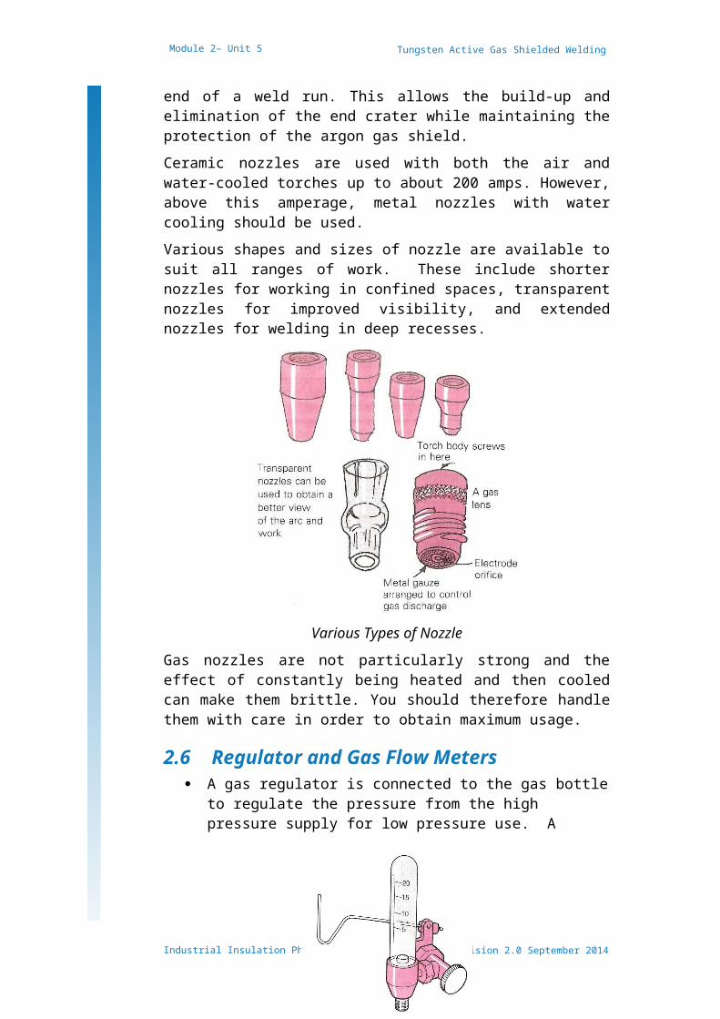
Ceramic nozzles are used with both the air and water-cooled torches up to about 200 amps. However, above this amperage, metal nozzles with water cooling should be used.Various shapes and sizes of nozzle are available to suit all ranges of work. These include shorter nozzles for working in confined spaces, transparent nozzles for improved visibility, and extended nozzles for welding in deep recesses.
Various Types of NozzleGas nozzles are not particularly strong and the effect of constantly being heated and then cooled can make them brittle. You should therefore handle them with care in order to obtain maximum usage.
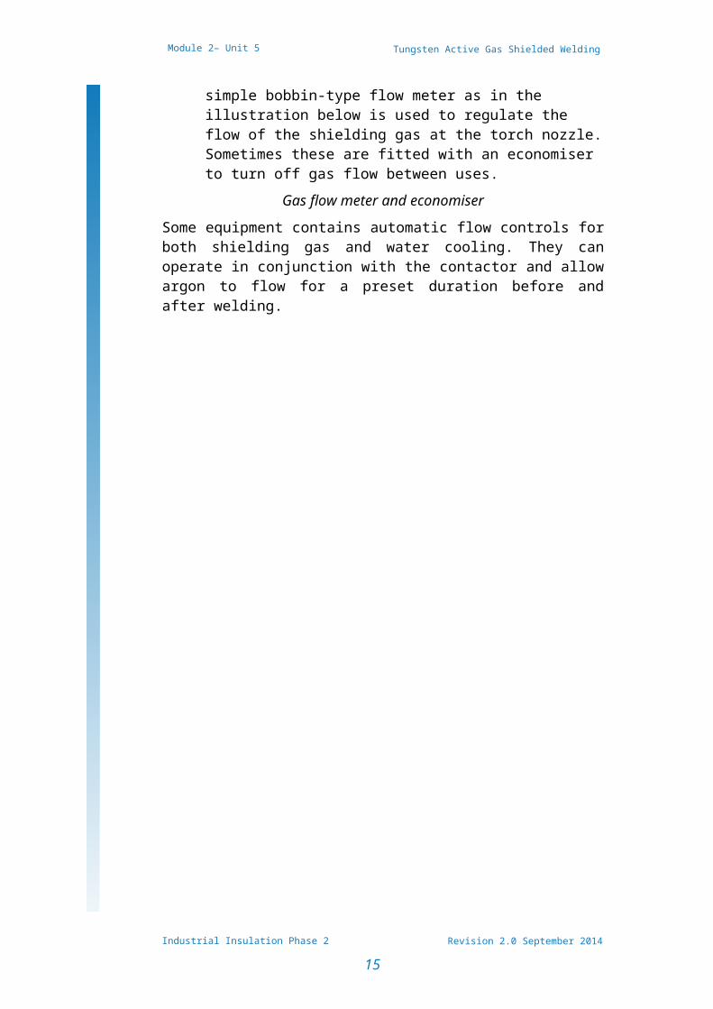
2.6 Regulator and Gas Flow Meters A gas regulator is connected to the gas bottle to
regulate the pressure from the high pressure supply for low pressure use. A simple bobbin-type flow meter as in the illustration below is used to regulate the flow of the shielding gas at the torch nozzle.
Industrial Insulation Phase 2
12
Tungsten Active Gas Shielded Welding (TAGS/TIG)
Revision 2.0 September 2014
Module 2– Unit 5
Sometimes these are fitted with an economiser to turn off gas flow between uses.
Gas flow meter and economiserSome equipment contains automatic flow controls for both shielding gas and water cooling. They can operate in conjunction with the contactor and allow argon to flow for a preset duration before and after welding.
Industrial Insulation Phase 2
13
Tungsten Active Gas Shielded Welding (TAGS/TIG)
Revision 2.0 September 2014
Module 2– Unit 5
2.7 Shielding Gases Used for TAGS Welding
Argon and helium are the two most commonly used shielding gases used for GTAW. The characteristics most desirable for shielding purposes are the chemical inertness of the gases and their ability to produce smooth arc action at high currents. Both gases are inert, causing an ionization effect in the welding arc. They protect the tungsten electrode and the molten weld pool from the atmosphere.Gas purity affects a weld. Metals will withstand small amounts of impurities, but, for the best results, the percent of inert gas used should be at least 99.9 percent pure.Argon is heavier than helium and may be supplied in liquid or gaseous form. Argon provides for good cleaning action. The flow rates are determined by the size of the tungsten and the gas cup diameter. Argon is suitable for welding similar and dissimilar metals and works well while welding in the vertical and overhead welding positions.Helium is a lighter inert gas. It can be distributed as a liquid, but is used more often as a compressed gas. It leaves the weld area faster than argon, and higher flow rates are necessary when using it.Helium produces a narrow but deep heat-affected zone (HAZ), which is good for welding on heavier metals. It is suitable for welding at high speeds and gives good coverage in vertical and overhead welding positions. It helps to increase the penetration, and when used as a back purge, it tends to flatten the pass of the weld bead. Helium is suitable for use on thicker nonferrous metals.Argon and helium mixtures are used when welders need the control of the argon and the penetration of the helium. This mixture is not necessary when welding plain carbon steels.Typical mixtures vary, depending on the application. It is often used for automatic welding applications.Argon and hydrogen mixtures are often used for welding of stainless steel. This mixture should not be used when welding plain carbon steels. The typical mixture is 95 percent argon and 5 percent hydrogen.Nitrogen can also be used as a shielding gas, but is rarely used because of its higher current requirements. It is suitable for welding copper.Welding-grade argon is supplied in steel cylinders painted light blue. The usual size of cylinder is 8.5 m³ charged at a pressure of 172 bar (2500 lbf/m²). Take care that the
Industrial Insulation Phase 2
14
Tungsten Active Gas Shielded Welding (TAGS/TIG)
Revision 2.0 September 2014
Module 2– Unit 5
cylinder pressure does not fall too low, as the moisture level of the gas can rise as the cylinder pressure falls.
Industrial Insulation Phase 2
15
Tungsten Active Gas Shielded Welding (TAGS/TIG)
Revision 2.0 September 2014
Module 2– Unit 5
3.0Hazards and Safety Precautions Associated with TAGS Welding
Key Learning Points The hazards and safety precautions associated with
TAGS welding are similar to those listed for MMA and MAGS welding.
Please refer to these modules for the hazards and recommend safety precautions to be observed.
3.1 Safety Precaution for TAGS WeldingUse light gloves when T.A.G.S. welding to avoid burning through radiation and H.F. burns between the fingers.We need some reference text here, which module and unit should they refer to?
Industrial Insulation Phase 2
16
Tungsten Active Gas Shielded Welding (TAGS/TIG)
Revision 2.0 September 2014
Module 2– Unit 5
4.0Electrodes for TAGS WeldingKey Learning Points
Identify different types of electrodes used for TAGS welding
Identify the different sizes and profiles of electrodes used for TAGS welding
Identify the purpose of filler wire for TAGS welding.
4.1 Electrodes for TAGS WeldingPure tungsten electrodes were originally used for TIG welding, however to improve the quality of tungsten electrodes, certain additions can be made during manufacture. The main elements added are either zirconium or thorium. These help to reduce tungsten inclusions in the weld, which increases the current-carrying capacity and the life of the electrode while also giving improved arc stability.Thoriated and zirconiated types give easier starting and better arc stability and are generally preferred.
Thoriated tungsten electrodes contain 2% thoria (thorium oxide) and are used for dc welding with electrode negative for stainless and heat-resisting steels, mild and low alloy steels, copper, nickel, titanium and other metals.
Zirconiated tungsten electrodes contain 2% zirconia (zirconium oxide) and are recommended for ac welding of aluminium and its alloys, as zirconiated electrodes give better arc characteristics with these materials.
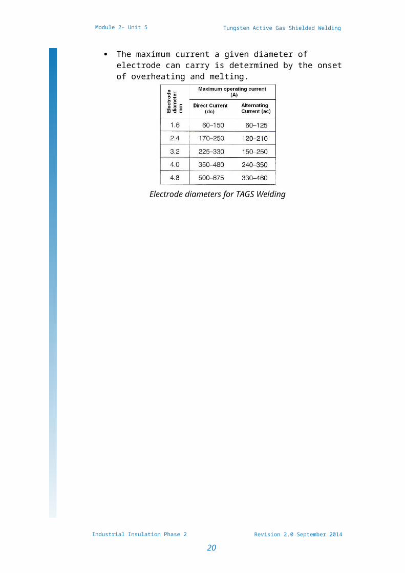
The diameter of the electrode is chosen to match the current. The minimum current depends on arc stability.
The maximum current a given diameter of electrode can carry is determined by the onset of overheating and melting.
Industrial Insulation Phase 2
17
Tungsten Active Gas Shielded Welding (TAGS/TIG)
Revision 2.0 September 2014
Module 2– Unit 5
Electrode diameters for TAGS Welding
Industrial Insulation Phase 2
18
Tungsten Active Gas Shielded Welding (TAGS/TIG)
Revision 2.0 September 2014
Module 2– Unit 5
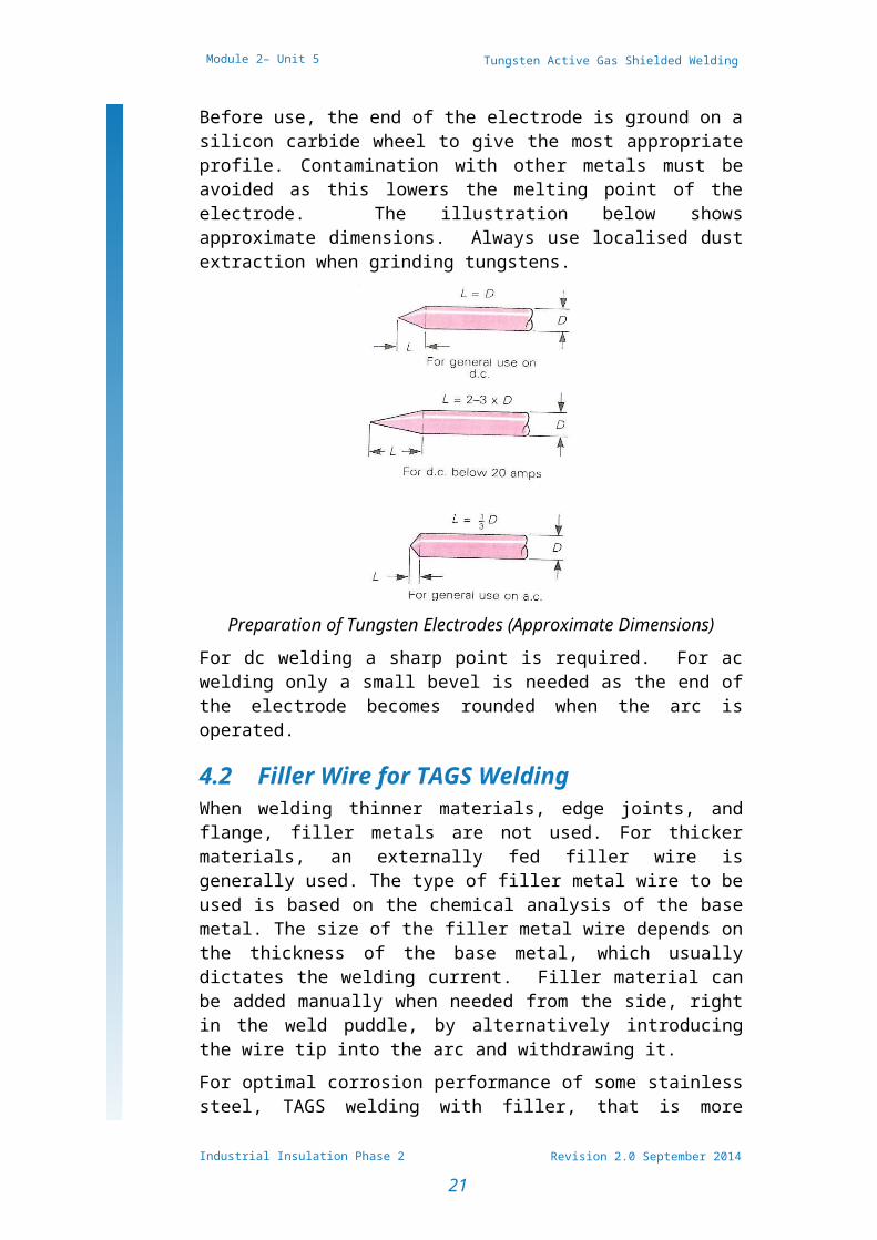
Before use, the end of the electrode is ground on a silicon carbide wheel to give the most appropriate profile. Contamination with other metals must be avoided as this lowers the melting point of the electrode. The illustration below shows approximate dimensions. Always use localised dust extraction when grinding tungstens.
Preparation of Tungsten Electrodes (Approximate Dimensions)
For dc welding a sharp point is required. For ac welding only a small bevel is needed as the end of the electrode becomes rounded when the arc is operated.
4.2 Filler Wire for TAGS WeldingWhen welding thinner materials, edge joints, and flange, filler metals are not used. For thicker materials, an externally fed filler wire is generally used. The type of filler metal wire to be used is based on the chemical analysis of the base metal. The size of the filler metal wire depends on the thickness of the base metal, which usually dictates the welding current. Filler material can be added manually when needed from the side, right in the weld puddle, by alternatively introducing the wire tip into the arc and withdrawing it.For optimal corrosion performance of some stainless steel, TAGS welding with filler, that is more highly alloyed with nickel relative to the base metal is a more reliable and effective method of maintaining the desired austenite-ferrite balance in the weld metal with mechanical properties and corrosion resistance equivalent to those of the base metal. Filler wire with a 7.0 to 9.0% nickel as compared to the 5.5% nickel typically in the base metal can be used.
Industrial Insulation Phase 2
19
Tungsten Active Gas Shielded Welding (TAGS/TIG)
Revision 2.0 September 2014
Module 2– Unit 5
5.0Set Up TAGS Welding Equipment
Key Learning Points Identify how to set up TAGS welding plant for
welding Identify different TAGS set-ups and complete TAGS
welding process on different materials Location and use of electricity emergency stop
button/s, gas shut off tap and fire extinguishers
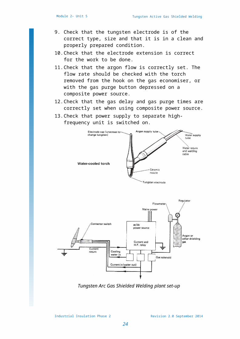
5.1 Generic Set-Up Procedure for TAGS Welding
The following are generic instructions for the setting up of a Tungsten-Arc Gas Shielded Welding plant. As there are many different suppliers of TAGS welding equipment is not possible to provide a specific check list.Equipment, particularly composite power sources, vary considerably in their control arrangements and therefore it is important to verify that actual equipment used is set-up correctly.Always1. Comply with the prescribed safety precautions and fire-
prevention procedure.2. Check that return lead is firmly connected to bench and
power source.3. Check that all connections to torch hose assembly are in
good order.4. Check that argon and water hoses are not 'kinked' or
otherwise obstructed.5. Check that power source is switched on.6. Check that argon cylinder valve is open.7. Check that the gas regulator is functioning properly.8. Check that correct size gas nozzle is fitted to torch.9. Check that the tungsten electrode is of the correct type,
size and that it is in a clean and properly prepared con-dition.
10. Check that the electrode extension is correct for the work to be done.
11. Check that the argon flow is correctly set. The flow rate should be checked with the torch removed from the
Industrial Insulation Phase 2
20
Tungsten Active Gas Shielded Welding (TAGS/TIG)
Revision 2.0 September 2014
Module 2– Unit 5
hook on the gas economiser, or with the gas purge but-ton depressed on a composite power source.
12. Check that the gas delay and gas purge times are cor-rectly set when using composite power source.
13. Check that power supply to separate high-frequency unit is switched on.
Tungsten Arc Gas Shielded Welding plant set-up
5.2 Preparation of Material Prior to Welding
CleaningCleaning the material to be welded is important. TAGS welds are often susceptible to contamination during welding. The surface to be welded must be free from oil, grease, paint, dirt, oxides, and other foreign material.Aluminum has an oxide coating that, if not removed, will contaminate the weld area. Cleaning solutions, wire
Industrial Insulation Phase 2
21
Tungsten Active Gas Shielded Welding (TAGS/TIG)
Revision 2.0 September 2014
Module 2– Unit 5
brushes, grinders, and abrasive blasting are some of the methods used to remove these contaminants.
Industrial Insulation Phase 2
22
Tungsten Active Gas Shielded Welding (TAGS/TIG)
Revision 2.0 September 2014
Module 2– Unit 5
Weld Jigs and Positioning of WeldsWeld jigs and positioning will also affect the shape, size, and uniformity of a weld. Fixtures hold the material to be welded in place while controlling distortion, helping to locate and maintain parts in their position relative to the weld.When weld jigs are employed, they can reduce the time for welding. Positioning will help move the weld into a flat position to improve productivity for the welder.Chill blocks, heat sinks, or backing bars may also be used when welding some metals to prevent burn-through, reduce base material temperatures, or to minimize distortion.
5.3 Procedure for TAGS Welding Technique
1. Hold the torch between the forefinger and thumb of the right hand. The handle of the torch should lie on the top of the hand hose assembly should be supported by fore-arm.
2. Lower the torch at an angle of about 70-80° until it is about 25 mm from the sheet surface at the right-hand end. With the welding current on, allow the argon to purge the hose of air and switch on the high-frequency start.
3. Position the welding shield and lower the torch gently towards the sheet. As the tungsten gets close to the sheet, a train of high-frequency sparks will initiate the arc and the high frequency will cut out.
4. Lower the torch to maintain an arc length of about 1.5 mm.
5. Once the molten pool has been formed, the technique is very similar to gas welding. Hold the filler rod in the left hand between the fingers and thumb, and feed it into the molten pool at an angle of approximately 10-20°
6. Always keep the end of the filler rod within the argon shroud, making contact with the weld pool but not touching the electrode.
7. If the filler touches the electrode, or the electrode touches the work, it can be contaminated and will have to be reground to shape.
8. As with gas welding, practice producing neat straight beads of weld on scrap plate before you attempt to join two pieces of plate together.
Industrial Insulation Phase 2
23
Tungsten Active Gas Shielded Welding (TAGS/TIG)
Revision 2.0 September 2014
Module 2– Unit 5
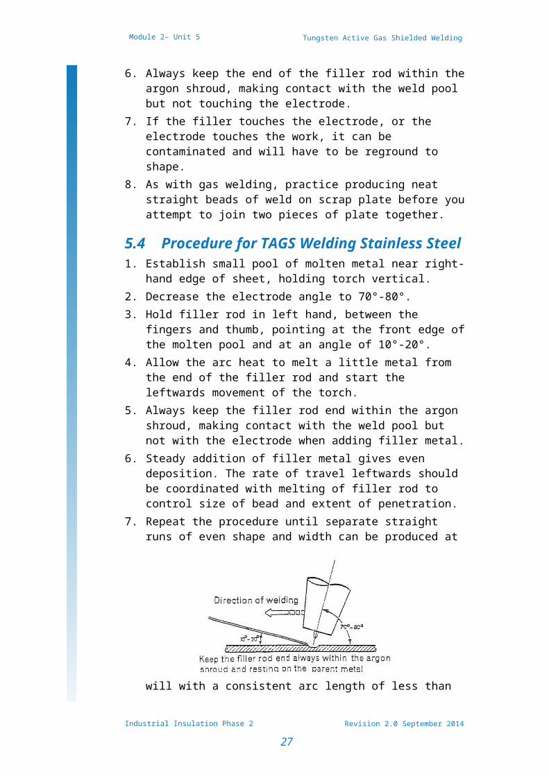
5.4 Procedure for TAGS Welding Stainless Steel
1. Establish small pool of molten metal near right-hand edge of sheet, holding torch vertical.
2. Decrease the electrode angle to 70°-80°.3. Hold filler rod in left hand, between the fingers and
thumb, pointing at the front edge of the molten pool and at an angle of 10°-20°.
4. Allow the arc heat to melt a little metal from the end of the filler rod and start the leftwards movement of the torch.
5. Always keep the filler rod end within the argon shroud, making contact with the weld pool but not with the elec-trode when adding filler metal.
6. Steady addition of filler metal gives even deposition. The rate of travel leftwards should be coordinated with melting of filler rod to control size of bead and extent of penetration.
7. Repeat the procedure until separate straight runs of even shape and width can be produced at will with a consistent arc length of less than 1/8˝ (3.0 mm). Do not
allow parent metal to become over-heated.
Material16 s.w.g. (1.5 mm) stainless steel, 1 off, min. 4˝ (10.0 cm) x 6˝ (15.0 cm).
Preparation Clean surface.
Assembly
Support sheet in flat position, long axis, and parallel to bench front.
Electrode 1/16˝ (1.5 mm)
Argon 5-8 ft.³/hr.
Industrial Insulation Phase 2
24
Tungsten Active Gas Shielded Welding (TAGS/TIG)
Revision 2.0 September 2014
Module 2– Unit 5
Current 50-70 amperes
Filler 1/16˝ (1.5 mm)
Industrial Insulation Phase 2
25
Tungsten Active Gas Shielded Welding (TAGS/TIG)
Revision 2.0 September 2014
Module 2– Unit 5
5.4 Procedure for TAGS Welding Aluminium
Material 16 s.w.g. (1.5 mm) aluminium, 1 off, min. 4˝ (10.0 cm) x 8˝ (20.0 cm).
Preparation
Surface cleaned immediately before welding.
Assembly as for EP 43.
Electrode 3/32˝ (2.5 mm)
Argon 8-12 ft.³/hr.
Current 50-75 amperes
Filler 3/32˝ (2.5 mm)
1. Commence welding at the right-hand edge of the sheet.2. The torch and filler rod should be held in the same man-
ner as for EP43, taking great care that the filler rod end is kept within the argon shroud.
3. The weld pool will not be so clear as when welding cor-rosion-resistant steel but the slight oxide film will be disintegrated and removed so that it causes no difficulty in observing the weld pool.
4. Co-ordinate the leftwards movement and the addition of filler metal to build up a reinforcement bead of even height and width.
Visual ExaminationExamine deposited beads and note any variations in width or height of run or depth of fusion into parent metal. These may be caused by variations in arc length, rate of travel, rate of addition of filler metal. Assess causes and take appropriate corrective action.The reverse side of the sheet should indicate traces of penetration without any burn-through.
Industrial Insulation Phase 2
26
Tungsten Active Gas Shielded Welding (TAGS/TIG)
Revision 2.0 September 2014
Module 2– Unit 5
Exercises Read and interpret drawing related to welding
exercises Assemble, adjust and operate a TAGS welding plant to
complete exercises listed below. Complete welding exercises No. 2.2.5a Complete welding exercises No. 2.2.5b Complete welding exercises No. 2.2.5c Complete welding exercises No. 2.2.5d Complete welding exercises No. 2.2.5e List the dangers/hazards and recommended safety
precautions pertaining to TAGS welding
Additional ResourcesTitle Author Ref. CodeThe Induction Book, “Code of Behaviour & Health & Safety Guidelines”
SOLAS
Basic Welding and Fabrication W Kenyon ISBN 0-582-
00536-LFundamentals of Fabrication and Welding Engineering
FJM Smith ISBN 0-582-09799-1
Workshop processes, practices and materials, 3rd edition, Elsevier Science & Technology
Black, Bruce J 2004
ISBN-13: 9780750660730
New Engineering Technology
Lawrence Smyth & Liam Hennessy
ISBN 086 1674480
Videos Understanding welding fumes Welder on Site…Be Aware (Vocam) Powered hand tool safety (Vocam) Industrial Ergonomics (Vocam)
Available from:Vocam IrelandCircle Organisation LtdFriar Street, Thurles, Co Tipperary, Ireland
Industrial Insulation Phase 2
27
Tungsten Active Gas Shielded Welding (TAGS/TIG)
Revision 2.0 September 2014
Module 2– Unit 5
Tel: +353 504 24666
Industrial Insulation Phase 2
28
Castleforbes HouseCastleforbes Road
Dublin 1