unit 2 linkages
DESCRIPTION
mechanism of machineryTRANSCRIPT

Introduction We know that a machine is a device which receives energy and transforms it into some useful work. A machine consists of a number of parts or bodies. In this we shall study the mechanisms of the various parts or bodies from which the machine is assembled. This is done by making one of the parts as fixed, and the relative motion of other
parts is determined with respect to the fixed part. Kinematic Link or Element Each part of a machine, which moves relative to some other part, is known as a kinematic link (or simply link) or Element.
A l ink may consist of several parts, which are rigidly fastened together, so that they do not move relative to one another.
For example, in a reciprocating steam engine, as shown in Fig. 2.1, piston, piston rod and crosshead constitute One link; connecting rod with big and small end bearings constitute a second link; crank, crank shaft and flywheel a third link and the cylinder, engine frame and main bearings a fourth link.
Fig. 2 .1: Reciprocating steam engine.
A link or element needs not to be a rigid body, but it must be a resistant body. A body is said to be a resistant body
if it is capable of transmitting the required forces with negligible deformation. Thus a link should have the following two characteristics: 1. It should have relative motion, and
2. It must be a resistant body. Types of Links
In order to transmit motion, the driver and the follower may be connected by the following three types of l inks:
1. Rigid link. A rigid link is one which does not undergo any deformation while transmitting motion. Strictly speaking, rigid links do not exist. However, as the deformation of a connecting rod, crank etc. of a reciprocating
steam engine is not appreciable they can be considered as rigid links.
2. Flexible link. A flexible link is one which is partly deformed in a manner not to affect the transmission of
motion. For example, belts, ropes, chains and wires are flexible links and transmit tensile forces only. 3. Fluid link. A fluid link is one which is formed by having a fluid in a receptacle and the motion is transmitted through the fluid by pressure or compression only, as in the case of hydraulic presses, jacks and brakes.

Structure It is an assemblage of a number of resistant bodies (known as members) having no relative motion between them and meant for carrying loads having straining action. A railway bridge, a roof truss, machine frames etc., are the examples of a structure.
Difference between a Machine and a Structure
The following differences between a machine and a structure are:
1. The parts of a machine move relative to one another, whereas the members of a structure do not move relative to one another.
2. A machine transforms the available energy into some useful work, whereas in a structure no energy is transformed into useful work. 3. The links of a machine may transmit both power and motion, while the members of a structure transmit forces
only. Kinematic Pair The two links or elements of a machine, when in contact with each other, are said to form a pair. If the relative motion between them is completely or successfully constrained (i.e. in a definite direction), the pair is known as
kinematic pair. Types of Constrained Motions Following are the three types of constrained motions:
1. Completely constrained motion: When the motion between a pair is limited to a definite direction irrespective of the direction of force applied, then the motion is said to be a completely constrained motion. For example, the piston and cylinder (in a steam engine) form a pair and the motion of the piston is limited to a definite direction (i.e. it will only reciprocate) relative to the cylinder irrespective of the
direction of motion of the crank, as shown in Fig. 2.1.
The motion of a square bar in a square hole, as shown in Fig. 2.2, and the motion of a shaft with collars at each end in a circular hole, as shown in Fig. 2.3, are also examples of completely constrained motion.
Fig. 2 .2: Square bar in a square hole. Fig. 2 .3: Shaft with collars in a circular hole.
2. Incompletely constrained motion: When the motion between a pair can take place in more than one
direction, then the motion is called an incompletely constrained motion. The change in the direction of impressed force may alter the direction of relative motion between the pair. A circular bar or shaft in a

circular hole, as shown in Fig. 2.4, is an example of an incompletely constrained motion as it may either rotate or slide in a hole. These both motions have no relationship with the other.
Fig. 2 .4: Shaft in a circular hole.
3. Successfully constrained motion: When the motion between the elements, forming a pair, is such that the constrained motion is not completed by itself, but by some other means, then the motion is said to be successfully constrained motion. Consider a shaft in a foot-step bearing as shown in Fig. 2.5. The shaft may rotate in a bearing or it may move upwards. This is a case of incompletely constrained motion. But if
the load is placed on the shaft to prevent axial upward movement of the shaft, then the motion of the pair is said to be successfully constrained motion. The motion of an I.C. engine valve (these are kept on their seat by a spring) and the piston reciprocating inside an engine cylinder are also the examples of
successfully constrained motion.
Fig. 2 .5: Shaft in a foot step bearing.
Classification of Kinematic Pairs The kinematic pairs may be classified according to the following considerations:
1. According to the type of relative motion between the elements: The kinematic pairs according to type
of relative motion between the elements may be classified as discussed below: (a) Sliding pair: When the two elements of a pair are connected in such a way that one can only slide relative
to the other, the pair is known as a sliding pair. The piston and cylinder, cross -head and guides of a
reciprocating steam engine, ram and its guides in shaper, tail stock on the lathe bed etc. are the examples of a sliding pair. A l ittle consideration will show that a sliding pair has a completely constrained motion.
(b) Turning pair: When the two elements of a pair are connected in such a way that one can only turn or revolve about a fixed axis of another link, the pair is known as turning pair. A shaft with collars at both ends fitted into a circular hole, the crankshaft in a journal bearing in an engine, lathe spindle supported in

head stock, cycle wheels turning over their axles etc. are the examples of a turning pair. A turning pair also has a completely constrained motion.
(c) Rolling pair: When the two elements of a pair are connected in such a way that one rolls over another
fixed link, the pair is known as rolling pair. Ball and roller bearings are examples of rolling pair.
(d) Screw pair: When the two elements of a pair are connected in such a way that one element can turn about the other by screw threads, the pair is known as screw pair. The lead screw of a lathe with nut, and bolt with a nut are examples of a screw pair.
(e) Spherical pair: When the two elements of a pair are connected in such a way that one element (with spherical shape) turns or swivels about the other fixed element, the pair formed is called a spherical pair.
The ball and socket joint, attachment of a car mirror, pen stand etc., are the examples of a spherical pair.
2. According to the type of contact between the elements: The kinematic pairs according to the type of contact between the elements may be classified as discussed below :
(a) Lower pair: When the two elements of a pair have a surface contact when relative motion takes place
and the surface of one element slides over the surface of the other, the pair formed is known as lower
pair. It will be seen that sliding pairs, turning pairs and screw pairs form lower pairs.
(b) Higher pair: When the two elements of a pair have a line or point contact when relative motion takes place and the motion between the two elements is partly turning and partly sliding, then the pair is
known as higher pair. A pair of friction discs, toothed gearing, belt and rope drives, ball and roller bearings and cam and follower is the examples of higher pairs.
3. According to the type of closure: The kinematic pairs according to the type of closure between the elements may be classified as discussed below :
(a) Self closed pair: When the two elements of a pair are connected together mechanically in such a way
that only required kind of relative motion occurs, it is then known as self closed pair. The lower pairs are self closed pair.
(b) Force - closed pair: When the two elements of a pair are not connected mechanically but are kept in
contact by the action of external forces, the pair is said to be a force-closed pair. The cam and follower is an example of force closed pair, as it is kept in contact by the forces exerted by spring and gravity.
Kinematic Chain When the kinematic pairs are coupled in such a way that the last link is joined to the first link to transmit definite
motion (i.e. completely or successfully constrained motion), it is called a kinematic chain. In other words, a kinematic chain may be defined as a combination of kinematic pairs, joined in such a way that each link forms a part of two pairs and the relative motion between the links or elements is completely or successfully constrained. For example, the crankshaft of an engine forms a kinematic pair with the bearings which are fixed in a pair, the
connecting rod with the crank forms a second kinematic pair, the piston with the connecting rod forms a third pai r and the piston with the cylinder forms a fourth pair. The total combination of these links is a kinematic chain.
If each link is assumed to form two pairs with two adjacent links, then the relation between the number of pairs (p) forming a kinematic chain and the number of l inks (l) may be expressed in the form of an equation:
l = 2 p – 4 ………………………………… (I)
Since in a kinematic chain each link forms a part of two pairs, therefore there will be as many links as the number of pairs.
Another relation between the number of l inks (l) and the number of joints (j) which constitute a kinematic chain is given by the expression:
J=
……………………………………………. (II)
The equations (I) and (II) are applicable only to kinematic chains, in which lower pairs are used. These equations may also be applied to kinematic chains, in which higher pairs are used. In that case each higher pair may be taken as equivalent to two lower pairs with an additional element or l ink.
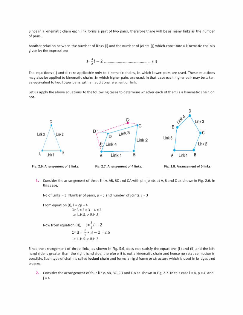
Let us apply the above equations to the following cases to determine whether each of them is a kinematic chain or not.
Fig. 2.6: Arrangement of 3 links. Fig. 2.7: Arrangement of 4 links. Fig. 2.8: Arrangement of 5 links.
1. Consider the arrangement of three links AB, BC and CA with pin joints at A, B and C as shown in Fig. 2.6. In this case,
No of Links = 3; Number of pairs, p = 3 and number of joints, j = 3
From equation (I), l = 2p – 4 Or 3 = 2 × 3 – 4 = 2 i.e. L.H.S. > R.H.S.
Now from equation (II), J=
Or 3 =
= 2.5
i .e. L.H.S. > R.H.S.
Since the arrangement of three links, as shown in Fig. 5.6, does not satisfy the equations (i ) and (ii) and the left hand side is greater than the right hand side, therefore it is not a kinematic chain and hence no relative motion is
possible. Such type of chain is called locked chain and forms a rigid frame or structure which is used in bridges a nd trusses.
2. Consider the arrangement of four l inks AB, BC, CD and DA as shown in Fig. 2.7. In this case l = 4, p = 4, and
j = 4

From equation (I), l = 2 p – 4 4 = 2 × 4 – 4 = 4
i.e. L.H.S. = R.H.S.
From equation (II), J=
Or 3 =
= 4
i .e. L.H.S. = R.H.S.
Since the arrangement of four l inks, as shown in Fig. 2.7, satisfies the equations (I) and (II), therefore it is a
kinematic chain of one degree of freedom. A chain in which a single link such as AD in Fig. 2.7 is sufficient to define the position of all other links, it is then
called a kinematic chain of one degree of freedom. A little consideration will show that in Fig. 2.7, if a definite displacement (say θ) is given to the link AD, keeping the link AB fixed, then the resulting displacements of the remaining two links BC and CD are also perfectly definite. Thus we see that in a four bar chain, the relative motion is completely constrained. Hence it may be called as a constrained kinematic chain, and it is the basis of all
machines .
3. Consider an arrangement of five l inks, as shown in Fig. 2.8. In this case, l = 5, p = 5, and j = 5
From equation (I), l = 2 p – 4 or 5 = 2 × 5 – 4 = 6 i.e. L.H.S. < R.H.S.
From equation (II), J=
Or 5 =
= 5.5
i .e. L.H.S. < R.H.S.
Since the arrangement of five l inks, as shown in Fig. 2.8 does not satisfy the equations and left hand side is less than right hand side, therefore it is not a kinematic chain. Such a type of chain is called unconstrained chain i .e. the relative motion is not completely constrained.
Types of Joints in a Chain The following types of joints are usually found in a chain :
1. Binary joint: When two links are joined at the same connection, the joint is known as binary joint.
For example, a chain as shown in Fig. 2.9, has four links and four binary joins at A, B, C and D.
Fig 2.9: Kinematic chain with all binary joints.
In order to determine the nature of chain, i .e. whether the chain is a locked chain (or structure) or kinematic chain
or unconstrained chain, the following relation between the number of l inks and the number of binary joints, as given by A.W. Klein, may be used:

…………………………….. (I)
Where j = Number of binary joints, h = Number of higher pairs, and l = Number of l inks. When h = 0, the equation (I), may be written as
………………………… (II)
Applying this equation to a chain, as shown in Fig.2.9, where l = 4 and j = 4, we have
= 4
Since the left hand side is equal to the right hand side, therefore the chain is a kinematic chain or constrained
chain.
2. Ternary joint: When three links are joined at the same connection, the joint is known as ternary joint.
It is Equivalent to two binary joints as one of the three links joined carry the pin for the other two links. For example, a chain, as shown in Fig. 2.10, has six links. It has three binary joints at A, B and D and two ternary joints at C and E. Since one ternary joint is equivalent to two binary joints, therefore equivalent
binary joints in a chain, as shown in Fig.2.10, are 3 + 2 × 2 = 7
Fig 2.10: Kinematic chain having binary and ternary joints.
Let us now determine whether this chain is a kinematic chain or not. We know that l = 6 and j = 7,
therefore from equation (II),
Or
7
= 7
Since left hand side is equal to right hand side, therefore the chain, as shown in Fig. 2.10, is a kinematic chain or constrained chain.
3. Quaternary joint: When four links are joined at the same connection, the joint is called a quaternary
joint.
It is equivalent to three binary joints. In general, when l numbers of l inks are joined at the same connection, the joint is equivalent to (l – 1) binary joints.

For example consider a chain having eleven links, as shown in Fig. 2.11 (a). It has one binary joint at D, four ternary joints at A, B, E and F, and two quaternary joints at C and G. Since one quaternary joint is
equivalent to three binary joints and one ternary joint is equal to two binary joints, therefore total number of binary joints in a chain, as shown in Fig. 2.11 (a), is
Fig 2.11(a): Locked chain having binary, ternary and quaternary joints.
1 + 4 × 2 + 2 × 3 = 15
Let us now determine whether the chain, as shown in Fig. 2.11 (a), is a kinematic chain or not. We know that l = 11 and j = 15. We know that,
Or
= 14.5, i.e., L.H.S. > R.H.S.
Since the left hand side is greater than right hand side, therefore the chain, as shown in Fig. 2.11 (a), is not a kinematic chain so such a type of chain is called locked chain and forms a rigid frame or structure.
If the link CG is removed, as shown in Fig. 2.11 (b), it has ten links and has one binary joint at D and six ternary joints at A, B, C, E, F and G. Therefore total number of binary joints is 1 + 2 × 6 = 13. We know that
Fig 2.11(b): Kinematic chain having binary & ternary joints.
Or
= 13, i.e., L.H.S. = R.H.S.

Since left hand side is equal to right hand side, therefore the chain, as shown in Fig. 2.11 (b), is a kinematic chain or constrained chain.
Note: A mechanism with four links is known as simple mechanism, and the mechanism with more than four l inks is known as compound mechanism. When a mechanism is required to transmit power or to do some particular type of work, it then becomes a machine. In such cases, the various links or elements have to be des igned to withstand
the forces (both static and kinetic) safely. Number of Degrees of Freedom for Plane Mechanisms In the design or analysis of a mechanism, one of the most important concerns is the number of degrees of freedom (also called movability) of the mechanism. It is defined as the number of input parameters (usually pair variables)
which must be independently controlled in order to bring the mechanism into a useful engineering purpose. It is possible to determine the number of degrees of freedom of a mechanism directly from the number of l inks and the number and types of joints which it includes.
Fig 2.12 (a): Four bar chain. Fig 2.12 (b): Five bar chain.
Consider a four bar chain, as shown in Fig. 2.12 (a). A l ittle consideration will show that only one variable such as θ1
is needed to define the relative positions of all the links. In other words, we say that the number of degrees of freedom of a four bar chain is one.
Now, let us consider a five bar chain, as shown in Fig. 2.12 (b). In this case two variables such as θ1 and θ2 are
needed to define completely the relative positions of all the links. Thus, we say that the number of degrees of freedom is two.
In order to develop the relationship in general, consider two links AB a nd CD in a plane motion as shown in Fig. 2.13 (a).
Fig 2.13: Links in a plane motion.

The link AB with co-ordinate system OXY is taken as the reference link (or fixed link). The position of point P on the moving link CD can be completely specified by the three variables, i .e. the co-ordinates of the point P denoted by x
and y and the inclination θ of the link CD with X-axis or link AB. In other words, we can say that each link of a mechanism has three degrees of freedom before it is connected to any other l ink. But when the link CD is connected to the link AB by a turning pair at A, as shown in Fig. 2.13 (b), the position of link CD is now determined by a single variable θ and thus has one degree of freedom.
From above, we see that when a link is connected to a fixed link by a turning pair (i.e. lower pair) , two degrees of freedom are destroyed. This may be clearly understood from Fig. 2.14, in which the resulting four bar mechanism has one degree of fr eedom (i.e. n = 1).
Fig 2.14: Four bar mechanism.
Now let us consider a plane mechanism with l number of l inks. Since in a mechanism, one of the links is to be fixed, therefore the number of movable l inks will be (l – 1) and thus the total number of degrees of freedom will be 3 (l – 1) before they are connected to any other link. In general, a mechanism with l number of links connected b y j
number of binary joints or lower pairs (i.e. single degree of freedom pairs) and h number of higher pairs (i.e. two degree of freedom pairs), then the number of degrees of freedom of a mechanism is given by
n = 3 (l – 1) – 2 j – h …………………….... (I)
This equation is called Kutzbach criterion for the movability of a mechanism having plane motion. If there are no two degree of freedom pairs (i.e. higher pairs), then h = 0 . Substituting h = 0 in equation (I), we have
n = 3 (l – 1) – 2 j ………………………….. (II)
Application of Kutzbach Criterion to Plane Mechanisms We have discussed in the previous article that Kutzbach criterion for determining the number of degrees of
freedom or movability (n) of a plane mechanism is
n = 3 (l – 1) – 2 j – h
Fig 2.15: Plane mechanisms.

The number of degrees of freedom or movability (n) for some simple mechanisms having no higher pair (i.e. h = 0), as shown in Fig. 2.15, are determined as follows:
1. The mechanism, as shown in Fig. 2.15 (a), has three links and three binary joints, i .e. l = 3 and j = 3.
∴ n = 3 (3 – 1) – 2 × 3 = 0
2. The mechanism, as shown in Fig. 2.15 (b), has four links and four binary joints, i .e. l = 4 and j = 4.
∴ n = 3 (4 – 1) – 2 × 4 = 1
3. The mechanism, as shown in Fig. 2.15 (c), has five links and five binary joints, i .e. l = 5, and j = 5.
∴ n = 3 (5 – 1) – 2 × 5 = 2
4. The mechanism, as shown in Fig. 2.15 (d), has five links and six equivalent binary joints (because there are two binary joints at B and D, and two ternary joints at A and C), i .e. l = 5 and j = 6.
∴ n = 3 (5 – 1) – 2 × 6 = 0
5. The mechanism, as shown in Fig. 2.15 (e), has six links and eight equivalent binary joints (because there are four ternary joints at A, B, C and D), i .e. l = 6 and j = 8.
∴ n = 3 (6 – 1) – 2 × 8 = – 1
It may be noted that
(a) When n = 0, then the mechanism forms a structure and no relative motion between the links is possible, as shown in Fig. 2.15 (a) and (d). (b) When n = 1, then the mechanism can be driven by a single input motion, as shown in Fig. 2.15 (b).
(c) When n = 2, then two separate input motions are necessary to produce constrained motion for the mechanism, as shown in Fig. 2.15 (c).
(d) When n = – 1 or less, then there are redundant constraints in the chain and it forms a statically indeterminate structure, as shown in Fig. 2.15 (e).
The application of Kutzbach’s criterion applied to mechanisms with a higher pair or two degree of freedom joints is shown in Fig. 2.16.
Fig 2.16: Mechanism with a higher pair.
In Fig. 2.16 (a), there are three links, two binary joints and one higher pair, i .e. l = 3, j = 2 and h = 1.

n = 3 (3 – 1) – 2 × 2 – 1 = 1
In Fig. 2.16 (b), there are four links, three binary joints and one higher pair, i .e. l = 4, j = 3 and h = 1
n = 3 (4 – 1) – 2 × 3 – 1 = 2
Here it has been assumed that the slipping is possible between the links (i.e. between the wheel and the fixed link). However if the friction at the contact is high enough to prevent slipping, the joint will be counted as one
degree of freedom pair, because only one relative motion will be possible between the links.
Grubler’s Criterion for Plane Mechanisms The Grubler’s criterion applies to mechanisms with only single degree of fr eedom joints where the overall
movability of the mechanism is unity. Substituting n = 1 and h = 0 in Kutzbach equation, we have 1 = 3 (l – 1) – 2 j or 3l – 2j – 4 = 0
This equation is known as the Grubler's criterion for plane mechanisms with constrained motion. A l ittle consideration will show that a plane mechanism with a movability of 1 and only single degree of freedom joints cannot have odd number of links. The simplest possible mechanisms of this type are a four bar mechanism
and a slider-crank mechanism in which l = 4 and j = 4. Inversion of Mechanism When one of l inks is fixed in a kinematic chain, it is called a mechanism. So we can obtain as many mechanisms as the number of l inks in a kinematic chain by fixing, in turn, different links in a kinematic chain. This method of
obtaining different mechanisms by fixing different l inks in a kinematic chain is known as inversion of the mechanism. It may be noted that the relative motions between the various links is not changed in any manner through the
process of inversion, but their absolute motions (those measured with respect to the fixed link) may be changed drastically.
Note: The part of a mechanism which initially moves with respect to the frame or fixed link is called driver and that part of the mechanism to which motion is transmitted is called follower. Most of the mechanisms are reversible, so that same link can play the role of a driver and follower at different times. For example, in a reciprocating steam engine, the piston is the driver and flywheel is a follower while in a reciprocating air compr essor, the flywheel is a
driver. Types of Kinematic Chains The most important kinematic chains are those which consist of four lower pairs, each pair being a sliding pair or a turning pair. The following three types of kinematic chains with four lower pairs are important from the subject
point of view: 1. Four bar chain or quadric cyclic chain. 2. Single slider crank chain. 3. Double slider crank chain.
Four Bar Chain or Quadric Cycle Chain We know that the kinematic chain is a combination of four or more kinematic pairs, such that the relative motion between the links or elements is completely constrained. The simplest and the basic kinematic chain is a four bar chain or quadric cycle chain, as shown in Fig.2.17. It consists of four links, each of them forms a turning pair at A, B,

C and D. The four links may be of different lengths. According to Grashof’s law for a four bar mechanism, the sum of the shortest and longest l ink lengths should not be greater than the sum of the remaining two link lengths if
there is to be continuous relative motion between the two links.
Fig 2.17: Four bar chain
A very important consideration in designing a mechanism is to ensure that the input crank makes a complete
revolution relative to the other links. The mechanism in which no link makes a complete revolution will not be useful. In a four bar chain, one of the links, in particular the shortest l ink, will make a complete revolution rela tive to the other three links, if it satisfies the Grashof’s law. Such a link is known as crank or driver. In Fig. 2.17, AD (link 4) is a crank. The link BC (link 2) which makes a partial rotation or oscillates is known as lever or rocker or follower
and the link CD (link 3) which connects the crank and lever is called connecting rod or coupler. The fixed link AB (link 1) is known as frame of the mechanism. When the crank (link 4) is the driver, the mechanism is transforming rotary motion into oscillating motion.
Inversions of Four Bar Chain 1. Beam engine (crank and lever mechanism):
A part of the mechanism of a beam engine (also known as crank and lever mechanism) which consists of four l inks, is shown in Fig. 2.18. In this mechanism, when the crank rotates about the fixed centre A, the lever
oscillates about a fixed centre D. The end E of the lever CDE is connected to a piston rod which recipr ocates due to the rotation of the crank. In other words, the purpose of this mechanism is to convert rotary motion into reciprocating motion.
Fig 2.18: Beam engine.

2. Coupling rod of a locomotive (Double crank mechanism):
The mechanism of a coupling rod of a locomotive (also known as double crank mechanism) which consists of four links is shown in Fig. 2.19. In this mechanism, the links AD and BC (having equal length) act as cranks and are connected to the respective wheels. The link CD acts as a coupling rod and the link AB is fixed in order to maintain a constant centre to centre distance between them. This mechanism is meant for transmitting rotary motion from
one wheel to the other wheel.
Fig 2.19: Coupling rod of a locomotive.
Single Slider Crank Chain
A single slider crank chain is a modification of the basic four bar chain. It consists of one sliding pair and three turning pairs. It is usually found in reciprocating steam engine mechanism. This type of mechanism converts rotary
motion into reciprocating motion and vice versa. In a single slider crank chain, as shown in Fig. 2 .20, the links 1 and 2, links 2 and 3, and links 3 and 4 form three turning pairs while the links 4 and 1 form a sliding pair.
Fig. 2.20: S ingle slider crank chain.

The link 1 corresponds to the frame of the engine, which is fixed. The link 2 corresponds to the crank; link 3 corresponds to the connec ting rod and link 4 corresponds to cross -head. As the crank rotates, the cross -head
reciprocates in the guides and thus the piston reciprocates in the cylinder.
Inversions of Single Slider Crank Chain 1. Pendulum pump or Bull engine:
In this mechanism, the inversion is obtained by fixing the cylinder or link 4 (i.e. sliding pair), as shown in Fig. 2.21. In this case, when the crank (link 2) rotates, the connecting rod (link 3) oscillates about a pin pivoted to the fixed
link 4 at A and the piston attached to the piston rod (link 1) reciprocates. The duplex pump which is used to supply feed water to boilers have two pistons attached to link 1, as shown in Fig. 2.21.
Fig. 2.21: Pendulum pump.
2. Oscillating cylinder engine:
The arrangement of oscillating cylinder engine mechanism, as shown in Fig. 2.22, is used to convert reciprocating motion into rotary motion. In this mechanism, the link 3 forming the turning pair is fixed. The link 3 corresponds to
the connecting rod of a reciprocating steam engine mechanism. When the crank (link 2) rotates, the piston attached to piston rod (link 1) reciprocates and the cylinder (link 4) oscillates about a pin pivoted to the fixed link at A.
Fig. 2.22: Oscillating cylinder engine.

Double Slider Crank Chain
A kinematic chain which consists of two turning pairs & two sliding pairs is known as double slider crank chain, as shown in Fig. 2.23. We see that the link 2 and link 1 form one turning pair and link 2 and link 3 form the second turning pair. The link 3 and link 4 form one sliding pair and link 1 and link 4 form the second sli ding pair.
Fig. 2.23: Elliptical trammels.
Inversions of Double Slider Crank Chain 1. Elliptical trammels:
It is an instrument used for drawing ellipses. This inversion is obtained by fixing the slotted plate (l ink 4), as shown in Fig. 2.23. The fixed plate or l ink 4 has two straight grooves cut in it, at right angles to each other. The link 1 and link 3, are known as sliders and form sliding pairs with link 4. The link AB (link 2) is a bar which forms turning pair
with links 1 and 3. When the links 1 and 3 slide along their respective grooves, any point on the link 2 such as P traces out an ellipse on the surface of l ink 4, as shown in Fig. 5.34 (a). A little consideration will show that AP and BP are the semi-major axis and semi-minor axis of the ellipse respectively. This can be proved as follows:
Let us take OX and OY as horizontal and vertical axes and let the link BA is inclined at an angle θ with the horizontal, as shown in Fig. 2.23 (b). Now the co-ordinates of the point P on the link BA will be
x = PQ = AP cos θ; and y = PR = BP sin θ
Or
= Cos θ;
= Sin θ
Squaring and adding,
This is the equation of an ellipse. Hence the path traced by point P is an ellipse whose semi major axis is AP and semi-minor axis is BP.

Scotch yoke mechanism:
This mechanism is used for converting rotary motion into a reciprocating motion. The inversion is obtained by fixing either the link 1 or link 3. In Fig. 2.24, link 1 is fixed. In this mechanism, when the link 2 (which corresponds to crank) rotates about B as centre, the link 4 (which corresponds to a frame) reciprocates. The fixed link 1 guides the frame.
Fig. 2.24: Scotch yoke mechanism. Fig. 2.24: Scotch yoke mechanism.
Crank and slotted lever quick return motion mechanism:
This mechanism is mostly used in shaping machines, slotting machines and in rotary internal combustion engines.
In this mechanism, the link AC (i.e. l ink 3) forming the turning pair is fixed, as shown in Fig. 2.25. The link 3 corresponds to the connecting rod of a reciprocating steam engine. The driving crank CB revolves with uni form angular speed about the fixed centre C. A sliding block attached to the crank pin at B slides along the slotted bar AP and thus causes AP to oscillate about the pivoted point A. A short l ink PR transmits the motion from AP to the ram
which carries the tool and reciprocates along the line of stroke R1R2. The line of stroke of the ram (i.e. R1R2) is perpendicular to AC produced.
Fig. 2.25: Crank and slotted lever quick return motion mechanism.

Fig 2.25 (a): Return Stroke Fig 2.25 (a): Cutting Stroke
In the extreme positions, AP1 and AP2 are tangential to the circle and the cutting tool is at the end of the stroke. The forward or cutting stroke occurs when the crank rotates from the position CB1 to CB2 (or through an angle β) in the clockwise direction. The return stroke occurs when the crank rotates from the position CB2 to CB1 (or
through angle α) in the clockwise direction. Since the crank has uniform angular speed, therefore,
=
=
=
Since the tool travels a distance of R1 R2 during cutting and return stroke, therefore travel of the tool or length of stroke
= R1R2 = P1P2 = 2P1Q = 2AP1 sin P1 AQ
= 2AP1 sin (90 -
) = 2AP Cos
……… (∵AP1 = AP)
= 2 AP x
……… (∵Cos
=
)
= 2 AP x
………. (∵ )
From Fig.2.25 we see that the angle β made by the forward or cutting stroke is greater than the angle α described by the return stroke. Since the crank rotates with uniform angular speed, therefore the return stroke is completed
within shorter time. Thus it is called quick return motion mechanism. Toggle Mechanism:
This is a mechanism used to overcome a large resistance with a small driving force. Note that
and, for
a given value of F, P becomes very large for very small angle .

Fig 2.26 (a): Toggle Mechanism 3D Model Fig 2.26 (b): Schematic Diagram
Straight line mechanisms:
These are mechanisms designed so that a point on a coupler link of a linkage mechanism moves in a straight or
approximate straight-line path. To generate an exact straight line with only pin joints requires more than 4 links. At
least 6 links or 7 pin joints are needed to generate an exact straight line with pure revolute- jointed linkage i.e., a
watt's or Stephenson’s six bar. Some are shown below.
Figure 2.27: Straight Line Mechanisms
Intermittent Motion Mechanisms:
Very often there is a need to transform a continuous rotation of the driver into an intermittent motion of the
follower, for example, in such applications as film advances, indexing, motion along the production line, etc.
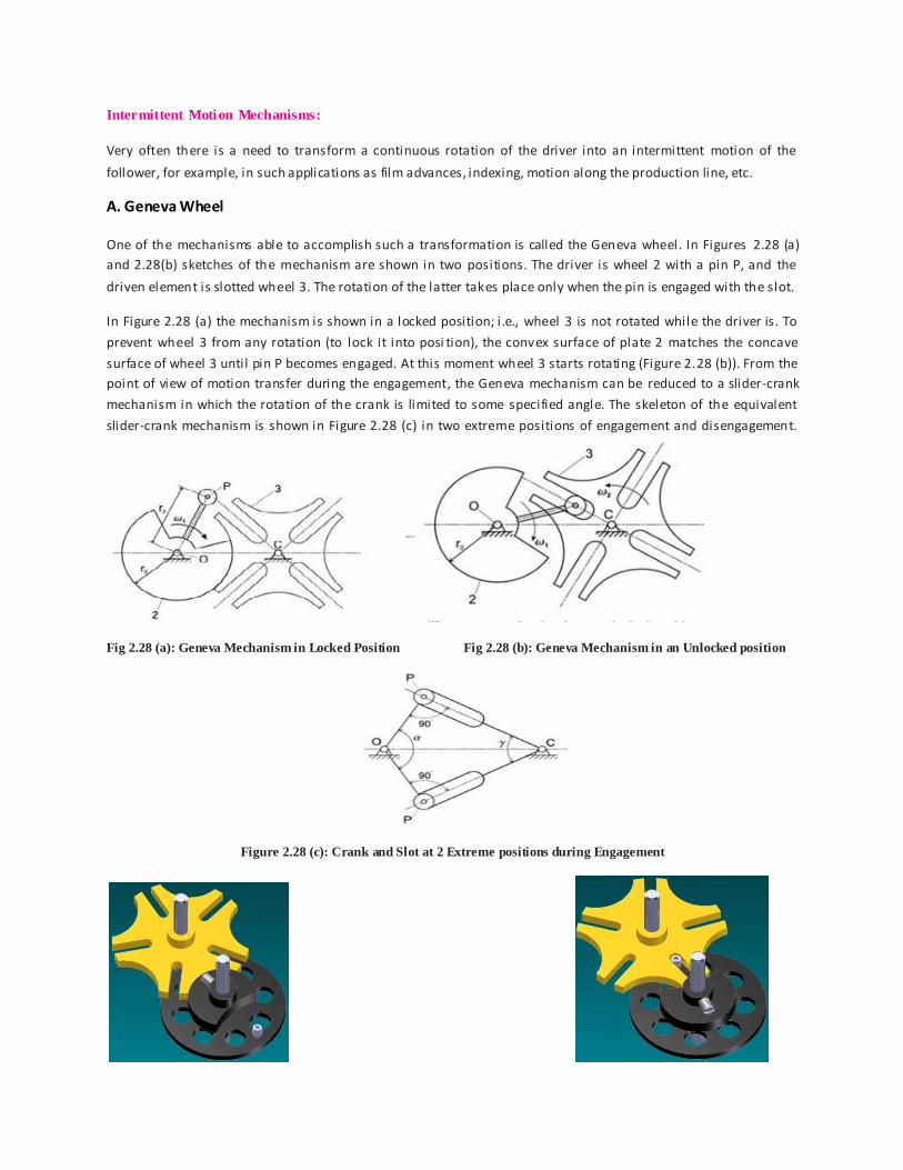
A. Geneva Wheel
One of the mechanisms able to accomplish such a transformation is called the Geneva wheel. In Figures 2.28 (a)
and 2.28(b) sketches of the mechanism are shown in two positions. The driver is wheel 2 with a pin P, and the
driven element is slotted wheel 3. The rotation of the latter takes place only when the pin is engaged with the slot.
In Figure 2.28 (a) the mechanism is shown in a locked position; i.e., wheel 3 is not rotated while the driver is. To
prevent wheel 3 from any rotation (to lock it into posi tion), the convex surface of plate 2 matches the concave
surface of wheel 3 until pin P becomes engaged. At this moment wheel 3 starts rotating (Figure 2.28 (b)). From the
point of view of motion transfer during the engagement, the Geneva mechanism can be reduced to a slider-crank
mechanism in which the rotation of the crank is limited to some specified angle. The skeleton of the equivalent
slider-crank mechanism is shown in Figure 2.28 (c) in two extreme positions of engagement and disengagement.
Fig 2.28 (a): Geneva Mechanism in Locked Position Fig 2.28 (b): Geneva Mechanism in an Unlocked position
Figure 2.28 (c): Crank and Slot at 2 Extreme positions during Engagement

B. Intermittent Gearing
Figure 2.29: Intermittent Gearing
Steering gear mechanisms:
Steering gear mechanism is based on double lever mechanism. It is used for changing the direction of wheels axis
with respect to chassis, so that the car can be moved in desired path. The relative motion between automobile and the road surface should be pure rolling. There should be line contact between road surface and tyre. This condition is possible only if the wheels describe concentric circles path while taking a turn. This requires the front wheel turns in a manner that the axes of both these wheels produced intersect with the instantaneous center (I) which li e
on the common axis of the rear wheels. This point shall be instantaneous center of rotation and the wheels shall roll without slipping.
Fig 2.30: Steering gear mechanisms

Now consider CGI
Cot =
or IG = b Cot ………………… (1)
From BHI
Cot θ =
or IH= b Cot θ ………………..… . (II)
Now IG= GH + HI i .e., b Cot = a + b Cot θ
a = b Cot - b Cot θ
a = b (Cot - Cot θ)
Cot - Cot θ =
Parallel mechanisms:
When the all the links in a mechanism are parallel to each other then the mechanism formed is a Parallel mechanism.
Fig 2.31: Parallel mechanisms