unit 2: power plant engineering ...the fire-tube boilers may be classified in several ways: 1-...
TRANSCRIPT
Unit 2: Power Plant Engineering http://www.ajourneywithtime.weebly.com/
1
Unit 2
Contents:
2.1 General layout of steam power plant
2.2 Power plant boilers or steam generator
2.2.1 Requirements of a good boiler
2.2.2 Basic Components of Boiler system
2.2.3 Classification of Boilers or Steam generator
2.2.4 Fire tube Boiler
2.2.4.1 Cochran Boiler
2.2.4.2 Lancashire Boiler
2.2.4.3 Locomotive Boiler
2.2.5 Water tube boiler
2.2.5.1 Babcock and Wilcox
2.2.5.2 Stirling boiler
2.2.5.3 Fluidised Bed Boiler
2.2.6 Compare Fire tube and water tube boilers
2.2.7 Boilers mountings and accessories
2.3 Burning or firing of Coal
2.4 Ash handling system
2.5 Dust collection system
2.6 Feed water treatment
2.7 Condenser
2.7.1 Cooling ponds and cooling Tower
2.8 Steam Turbine
2.9 Heat Balance & Efficiencies

Unit 2: Power Plant Engineering http://www.ajourneywithtime.weebly.com/
2
2.1 General layout of steam power plant
(i) A furnace to burn the fuel.
(ii) Steam generator or boiler containing water. Heat generated in the furnace is utilized to convert
water in steam.
(iii) Main power unit such as an engine or turbine to use the heat energy of steam and perform
work.
(iv) Piping system to convey steam and water.
In addition to the above equipment the plant requires various auxiliaries and accessories depending
upon the availability of water, fuel and the service for which the plant is intended.
Unit 2: Power Plant Engineering http://www.ajourneywithtime.weebly.com/
3
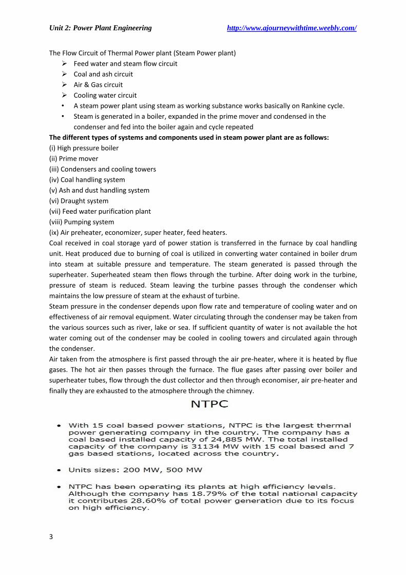
The Flow Circuit of Thermal Power plant (Steam Power plant)
Feed water and steam flow circuit
Coal and ash circuit
Air & Gas circuit
Cooling water circuit
• A steam power plant using steam as working substance works basically on Rankine cycle.
• Steam is generated in a boiler, expanded in the prime mover and condensed in the
condenser and fed into the boiler again and cycle repeated
The different types of systems and components used in steam power plant are as follows:
(i) High pressure boiler
(ii) Prime mover
(iii) Condensers and cooling towers
(iv) Coal handling system
(v) Ash and dust handling system
(vi) Draught system
(vii) Feed water purification plant
(viii) Pumping system
(ix) Air preheater, economizer, super heater, feed heaters.
Coal received in coal storage yard of power station is transferred in the furnace by coal handling
unit. Heat produced due to burning of coal is utilized in converting water contained in boiler drum
into steam at suitable pressure and temperature. The steam generated is passed through the
superheater. Superheated steam then flows through the turbine. After doing work in the turbine,
pressure of steam is reduced. Steam leaving the turbine passes through the condenser which
maintains the low pressure of steam at the exhaust of turbine.
Steam pressure in the condenser depends upon flow rate and temperature of cooling water and on
effectiveness of air removal equipment. Water circulating through the condenser may be taken from
the various sources such as river, lake or sea. If sufficient quantity of water is not available the hot
water coming out of the condenser may be cooled in cooling towers and circulated again through
the condenser.
Air taken from the atmosphere is first passed through the air pre-heater, where it is heated by flue
gases. The hot air then passes through the furnace. The flue gases after passing over boiler and
superheater tubes, flow through the dust collector and then through economiser, air pre-heater and
finally they are exhausted to the atmosphere through the chimney.

Unit 2: Power Plant Engineering http://www.ajourneywithtime.weebly.com/
4
2.2 Power plant boilers or steam generator
Boiler: it is defined as an enclosed vessel in which steam is produced from water by application of
heat. Usually boilers are coal or oil fired. A boiler should fulfil the following requirements.
Safety
Accessibility
Capacity
Efficient
Simple in construction & low maintenance cost
Performance of the boiler may be measured in term of its evaporative capacity also called power
of a boiler. It is defined as the amount of water evaporated or steam produced in Kg/hr or Kg/Sec
2.2.1 Requirements of a good boiler
A good boiler must possess the following qualities:
1. The boiler should be capable to generate steam at the required pressure and quantity as quickly
as possible with minimum fuel consumption.
2. The initial cost, installation cost and the maintenance cost should be as low as possible.
3. The boiler should be light in weight, and should occupy small floor area.
4. The boiler must be able to meet the fluctuating demands without pressure fluctuations.
5. All the parts of the boiler should be easily approachable for cleaning and inspection.
6. The boiler should have a minimum of joints to avoid leaks which may occur due to expansion and
contraction.
7. The boiler should be erected at site within a reasonable time and with minimum labour.
8. The water and flue gas velocities should be high for high heat transfer rates with minimum
pressure drop through the system.
9. There should be no deposition of mud and foreign materials on the inside surface and soot
deposition on the outer surface of the heat transferring parts.
10. The boiler should conform to the safety regulations as laid down in the Boiler Act.
2.2.2 Basic Components of Boiler system
• Boiler feed water heaters or furnace and fuel burning equipment, water walls, boiler surface
(drum and tube), Super heater, air heater (pre-heater) , Economizer (feed water heating)
and several accessories.
• In addition, there are sets of controls to monitor water and steam flow, fuel flow, airflow
and chemical treatment additions.
2.2.3 Classification of Boilers or Steam generator
Based on relative flow of flue gases and water
Fire tube Boiler
Water tube boiler
Based on circulation of water
Forced circulation
Natural Circulation
Based on the pressure of steam production
High pressure boiler
Low pressure boiler

Unit 2: Power Plant Engineering http://www.ajourneywithtime.weebly.com/
5
Based on Steam Delivery Condition
Wet
Dry saturated
Super heated
Based on position of furnace
Internally fired
Externally fired
Based on position of principle axis
Vertical
Horizontal
Inclined
Based on Position
Stationary
Mobile, (Marine, Locomotive)
2.2.4 Fire tube Boiler
In this type, the hot combustion gases are passed inside the tubes, and the tubes are surrounded
with water.
The fire-tube boilers may be classified in several ways:
1- Externally or internally fired.
2- Horizontal, vertical or inclined.
3- Direct tube or return tube.
Advantages:
1. Fire tube boilers are cheaper for smaller pressure and they are capable of meeting large
fluctuations in steam demands due to greater water storage in the drum.
2. Doors in the front and rear of the boiler drum provide access to the tubes for cleaning.
Disadvantages:
1. Since the water and steam are held in a drum, an increase of working pressure need using of
thicker plat sections for construction. The max. pr. Is limited.
2. Longer time is required for steam rising due to large quantity of water in the drum.
Example: Cochran, Lancashire and locomotive boiler

Unit 2: Power Plant Engineering http://www.ajourneywithtime.weebly.com/
6
Fig. Oil fired fire tube boiler
2.2.4.1 Cochran Boiler
Vertical multi-tubular boiler has horizontal fire tube. It consists of a cylindrical shell with its
crowns having a spherical shape. The furnace is also hemi-spherical. The grate is also placed
at the bottom of the furnace and ash-pit is located below the gate. It is very compact and
required minimum floor area. Any type of fuel can be used. It is used for small capacity
requirement.
Specifications:
Shell dia: 2.75 m Height: 5.79 Working Pressure: 6.5 bar Steam Capacity: 3500 Kg/hr (max up
to 4000 kg/hr) Efficiency: 70 to 75 %
Fig: Cochran Boiler

Unit 2: Power Plant Engineering http://www.ajourneywithtime.weebly.com/
7
2.2.4.2 Lancashire Boiler
Specifications: Stationary fire
tube, internally fired, horizontal natiral circulation boiler.
Max working pressure: 16 bar
Steam Capacity: 9000 Kg/hr
Efficiency: 50 to 70 %
2.2.4.3 Locomotive Boiler
horizontal fire tube type mobile boiler
produce steam at a very high rate
It consists of a shell or barrel of 1.5 meter in diameter and 4 meters in length.
The cylindrical shell is fitted to a rectangular firebox
It is very compact. The pressure of the steam
is limited to about 20 bar
Unit 2: Power Plant Engineering http://www.ajourneywithtime.weebly.com/
8
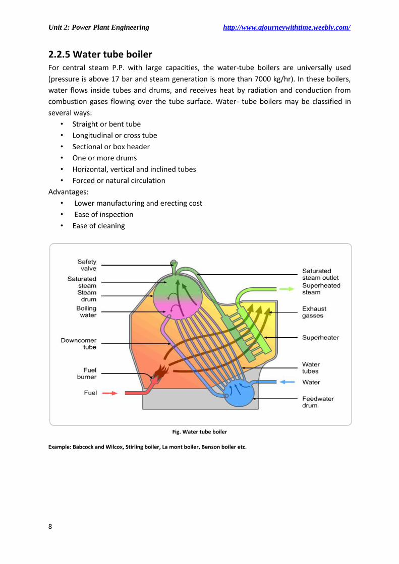
2.2.5 Water tube boiler For central steam P.P. with large capacities, the water-tube boilers are universally used
(pressure is above 17 bar and steam generation is more than 7000 kg/hr). In these boilers,
water flows inside tubes and drums, and receives heat by radiation and conduction from
combustion gases flowing over the tube surface. Water- tube boilers may be classified in
several ways:
• Straight or bent tube
• Longitudinal or cross tube
• Sectional or box header
• One or more drums
• Horizontal, vertical and inclined tubes
• Forced or natural circulation
Advantages:
• Lower manufacturing and erecting cost
• Ease of inspection
• Ease of cleaning
Fig. Water tube boiler
Example: Babcock and Wilcox, Stirling boiler, La mont boiler, Benson boiler etc.

Unit 2: Power Plant Engineering http://www.ajourneywithtime.weebly.com/
9
2.2.5.1 Babcock and Wilcox
Longitudinal drum boiler with superheated tubes. The straight inclined parallel tubes are rolled into header at each end, and placed below the longitudinal drum. The drum may be placed cross-wise with respect to the tubes. Incline tubes in parallel connect the two headers (box header). The rear header is provided at the bottom, called the mud drum, to collect solids in the boiler water. Specification:
• Cross-drum type • Pressure: 12-100 bar • Steam capacity; 0.63-63 kg/sec
2.2.5.2 Stirling boiler
The bent tube boiler is one of the most commonly used due to its simplicity. The headers are eliminated there by reducing maintenance costs. The bent tubes inter directly into the drum. They are arranged to give good circulation. As shown in the following fig. , Three drums are used, each at different levels. Water circulates from the upper most drum to the lower most drum, then into intermediate drum, and finally to the upper drum which contains the direct steam. Specifications:
• Bent-tube boiler • Pressure: 60 bar and more • Steam capacities: 12 kg/sec and more
High pressure boilers (> 100 bar): for detailed description refers book
• LA MONT BOILER (high pressure water tube boiler of forced circulation)
• BENSON BOILER (super critical high pressure boiler)

Unit 2: Power Plant Engineering http://www.ajourneywithtime.weebly.com/
10
2.2.5.3 FLUIDISED BED Boiler
Fluidised bed boiler produce steam by using fluidized bed combustion technique. In these
techniques, pulverised coal is put in form of bed on a grate and air is passed from dew side.
Due to air drag, the small particle is suspended in air and complete coal bed is appeared to
be flowing in air like fluid. Due to this inter mixing of particle is very good and complete
combustion is achieved so it has higher efficiency.
These are two types:
Bubbling fluidised bed boiler
Circulating fluidised bed boiler
Fluidised bed combustion (FBC)
Principle of FBC: When a gas is passed through a packed be of finely divided solid particle, it experiences a pressure drop drop across the bed. At low gas velocities, this pressure drop is small and doesn’t the particles. But if gas velocity is increased further, a state is reached, when particles are suspended in the gas stream and the packed bed becomes a fluidised bed. With further increase in gas velocity, the bed become turbulent and rapid mixing of particle occurs. In general, the behavior of this mixture of solid particles and gas is kike a fluid burning of a fuel in such a state is know as a fluidised bed combustion
Various advantages of FBC system are as follows:
(i) FBC system can use any type of low grade fuel including municipal wastes and therefore is a
cheaper method of power generation.
(ii) It is easier to control the amount of SO2 and NOX, formed during burning. Low emission of SO2
and NOX will help in controlling the undesirable effects of SO2 and NOX during combustion. SO2
emission is nearly 15% of that in conventional firing methods.
(iii) There is a saving of about 10% in operating cost and 15% in the capital cost of the power plant.
(iv) Ability to burn coal especially of high ash content and inferior coals.
(v) Reduced environmental impact in terms of air pollution.
(vi) Reduced water requirement.
(vii) Higher reliability and availability
Unit 2: Power Plant Engineering http://www.ajourneywithtime.weebly.com/
11
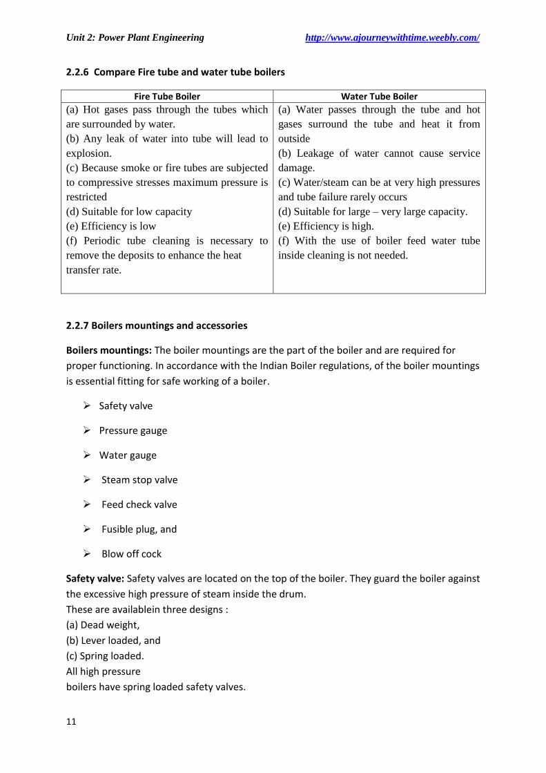
2.2.6 Compare Fire tube and water tube boilers
Fire Tube Boiler Water Tube Boiler
(a) Hot gases pass through the tubes which
are surrounded by water.
(b) Any leak of water into tube will lead to
explosion.
(c) Because smoke or fire tubes are subjected
to compressive stresses maximum pressure is
restricted
(d) Suitable for low capacity
(e) Efficiency is low
(f) Periodic tube cleaning is necessary to
remove the deposits to enhance the heat
transfer rate.
(a) Water passes through the tube and hot
gases surround the tube and heat it from
outside
(b) Leakage of water cannot cause service
damage.
(c) Water/steam can be at very high pressures
and tube failure rarely occurs
(d) Suitable for large – very large capacity.
(e) Efficiency is high.
(f) With the use of boiler feed water tube
inside cleaning is not needed.
2.2.7 Boilers mountings and accessories
Boilers mountings: The boiler mountings are the part of the boiler and are required for
proper functioning. In accordance with the Indian Boiler regulations, of the boiler mountings
is essential fitting for safe working of a boiler.
Safety valve
Pressure gauge
Water gauge
Steam stop valve
Feed check valve
Fusible plug, and
Blow off cock
Safety valve: Safety valves are located on the top of the boiler. They guard the boiler against
the excessive high pressure of steam inside the drum.
These are availablein three designs :
(a) Dead weight,
(b) Lever loaded, and
(c) Spring loaded.
All high pressure
boilers have spring loaded safety valves.

Unit 2: Power Plant Engineering http://www.ajourneywithtime.weebly.com/
12
It provided to keep the boiler pressure within the safety limit.
The spring is set in such a way that the upward thrust of the steam is balanced by the
downward thrust of the spring. If the operating steam pressure exceeds this value,
the difference in the thrust open the lid upward as a result of which steam will be
released with hissing sound, the steams pressure inside the shell will go down till the
lid is forced down to be back on its seat or initial place
Fig: Spring Loaded Safety Valve
Pressure gauge:
A pressure gauge is fitted in front of boiler in such a position that the operator can
conveniently read it. It reads the pressure of steam in the boiler and is connected to steam
space by a siphon tube.
Water gauge or water level indicator: Water level indicator is located in front of boiler in
such a position that the level of water can easily be seen by attendant.
Steam stop valve: The steam stop valve is located on the highest part of the steam space. It
regulates the steam supply to use. The steam stop valve can be operated manually or
automatically.
Fusible plug: It is very important safety device, which protects the fire tube boiler against
overheating. It is located just above the furnace in the boiler.
Blow off cock: The function of blow-off cock is to discharge mud and other sediments
deposited in the bottom most part of the water space in the boiler, while boiler is in operation.
It can also be used to drain-off boiler water. Hence it is mounted at the lowest part of the
boiler. When it is open, water under the pressure rushes out, thus carrying sediments and
mud.
Boilers accessories: To increase the efficiency of boilers equipment like economiser, air pre
heater and super heater are added to the boiler. These are known as boiler accessories.
• Air Pre Heater
• Economiser
• Super Heater
• Feed Water Pump
• Condenser
• Evaporator

Unit 2: Power Plant Engineering http://www.ajourneywithtime.weebly.com/
13
Air Pre Heater:
It is a heat exchanger used to heat the air entering furnace by extracting heat from flue gas.
Combustion of fuel using hot air improves furnace temperature and also improves the thermal
efficiency of the boiler.
Economiser:
This is also a heat exchanger but heats the feed water again using flue gases. It is placed in
the path of flue gas just ahead of the air pre heater.
Super Heater:
The function of a superheated is to increase the temperature of the steam above its saturation
point.
There are two type of superheaters:
1. Convective superheater
2. Radiant superheater
Superheated steam has the following advantages:
Steam consumption of the turbine is reduced.
Losses due to condensation in the cylinders and steam pipes are reduced.
Erosion of turbine blade is eliminated.
Efficiency of the steam plant is increased.
Feed Water Pump:
• It forces the feed water into the boiler at the desirable operating pressure
There are two type of pumps used as a feed pumps:
1. Reciprocation pump: The reciprocating pump consists of a pump cylinder and a
piston. Inside the cylinder reciprocates a piston which displaces water.
2. Rotary pump: Rotary feed pump are centrifugal type and are commonly run either by
a small steam turbine or by an electric motor.
Condenser:
This is another type of heat exchanger used to condense exhaust steam from engine or
turbine.
Evaporator:
Found only in ships. It is used to get pure water from available sea (salt) water
Evaluation of Performance of boilers:
The performance of boiler may be measured in term of its evaporative capacity also called
power of boiler. It is defined as the amount of water evaporated or steam produced in Kg/hr
or Kg/sec
It may be expressed as in
Kg of steam/hr
Kg of steam/kg of fuel fired
Equivalent Evaporation:
• Generally the different boilers generate steam at different pressure and temperature
and as such have different amount of heat. Hence to compare the evaporative capacity
or performance of different boilers working under different conditions it become
imperative to provide a common base so that water be supposed to be evaporated
under standard conditions.

Unit 2: Power Plant Engineering http://www.ajourneywithtime.weebly.com/
14
• The standard conditions adopted are: temperature of feed water 100 ºC and converted
into dry and saturated steam at 100 ºC. as per these standard conditions 1 kg of water
at 100 ºC necessitates 2257 kj to get converted to steam at 100 ºC
So Equivalent Evaporation may be defined as the amount of water evaporated from
water at 100 ºC to dry and saturated steam at 100 ºC
2.2.5.6 Coal handling system:
The following Stages are involved in handling the coal
(i) Coal Delivery: The coal from supply points is delivered by ships or boats to power stations situated
near to sea or river whereas coal is supplied by rail or trucks to the power stations.
(ii) Unloading: The type of equipment to be used for unloading the coal received at the power station
depends on how coal is received at the power station. In case the coal is brought by railway wagons, ships
or boats, the unloading may be done by car shakes, rotary car dumpers, cranes, grab buckets and coal
accelerators. If coal is delivered by trucks, there is no need of unloading device as the trucks may dump the
coal to the outdoor storage.
(iii) Preparation: When the coal delivered is in the form of big lumps and it is not of proper size, the
preparation (sizing) of coal can be achieved by crushers, breakers, sizers driers and magnetic separators.
(iv) Transfer: After preparation coal is transferred to the dead storage by means of the following systems :
1. Belt conveyors.
2. Screw conveyors.
3. Bucket elevators.
4. Grab bucket elevators.
5. Skip hoists.
6. Flight conveyor.
(v) Storage of coal: It is desirable that sufficient quantity of coal should be stored. Storage of coal gives
protection against the interruption of coal supplies when there is delay in transportation of coal or due to
strikes in coal mines.
(vi) In Plant Handling: From the dead storage the coal is brought to covered storage (Live storage) (bins
or bunkers). In plant handling may include the equipment such as belt conveyors, screw conveyors, bucket
elevators etc. to transfer the coal
(vii) Coal weighing methods: Weigh Lorries, hoppers and automatic scales are used to weigh the quantity
coal.
(viii) Furnace Firing: The solid fuels are fired into the furnace where combustion takes place.
Unit 2: Power Plant Engineering http://www.ajourneywithtime.weebly.com/
15
2.3 Burning or firing of Coal
The solid fuels are fired into the furnace by the following methods :
Hand firing
Mechanical firing(Stokers)
Pulverized fuel firing
Mechanical stokers are commonly used to feed solid fuels into the furnace in medium and
large size power plants.
Type of Stokers:
Principles of Stokers:
The working of various types of stokers is based on the following two principles:
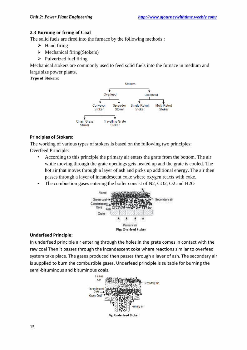
Overfeed Principle:
• According to this principle the primary air enters the grate from the bottom. The air
while moving through the grate openings gets heated up and the grate is cooled. The
hot air that moves through a layer of ash and picks up additional energy. The air then
passes through a layer of incandescent coke where oxygen reacts with coke.
• The combustion gases entering the boiler consist of N2, CO2, O2 and H2O
Fig: Overfeed Stoker
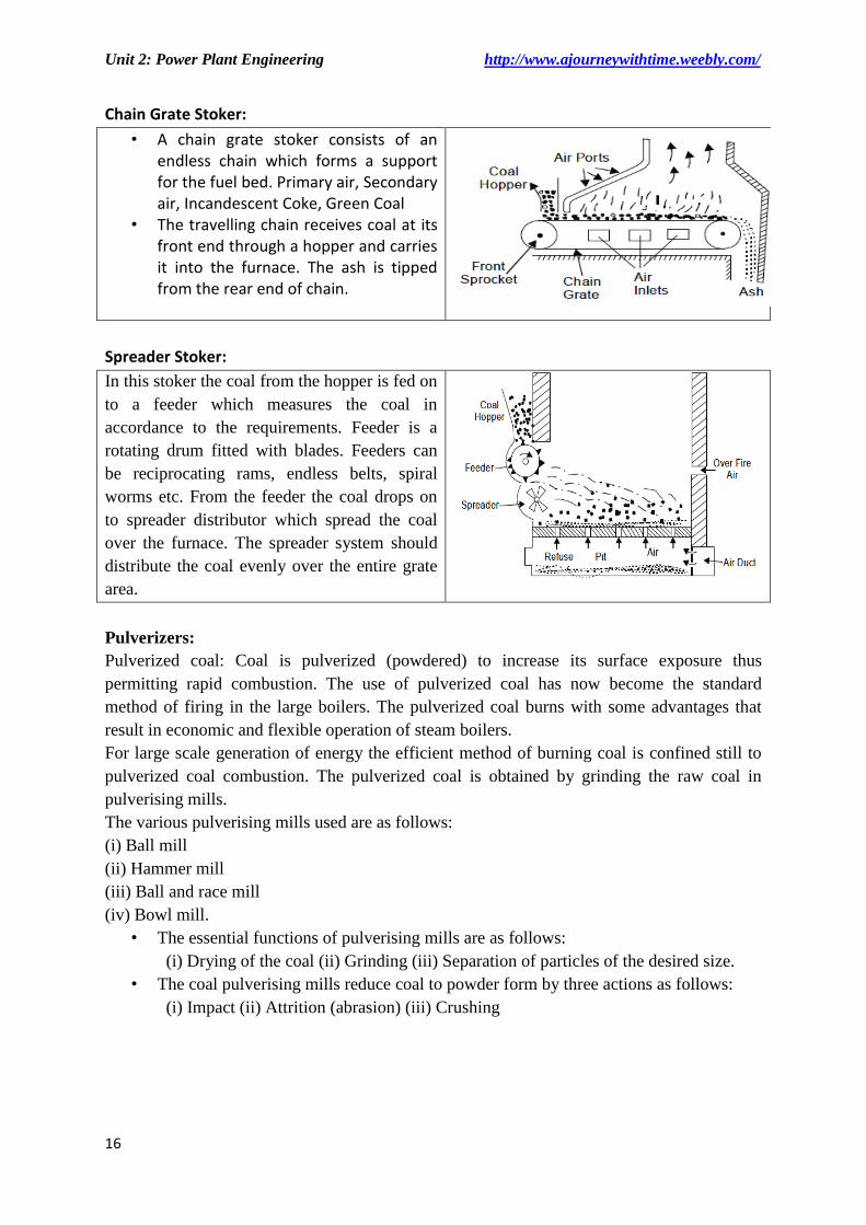
Underfeed Principle:
In underfeed principle air entering through the holes in the grate comes in contact with the
raw coal Then it passes through the incandescent coke where reactions similar to overfeed
system take place. The gases produced then passes through a layer of ash. The secondary air
is supplied to burn the combustible gases. Underfeed principle is suitable for burning the
semi-bituminous and bituminous coals.
Fig: Underfeed Stoker
Unit 2: Power Plant Engineering http://www.ajourneywithtime.weebly.com/
16
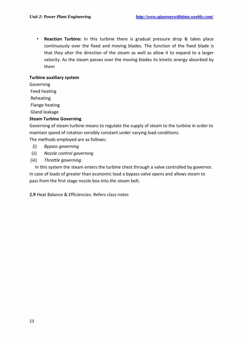
Chain Grate Stoker:
• A chain grate stoker consists of an endless chain which forms a support for the fuel bed. Primary air, Secondary air, Incandescent Coke, Green Coal
• The travelling chain receives coal at its front end through a hopper and carries it into the furnace. The ash is tipped from the rear end of chain.
Spreader Stoker:
In this stoker the coal from the hopper is fed on
to a feeder which measures the coal in
accordance to the requirements. Feeder is a
rotating drum fitted with blades. Feeders can
be reciprocating rams, endless belts, spiral
worms etc. From the feeder the coal drops on
to spreader distributor which spread the coal
over the furnace. The spreader system should
distribute the coal evenly over the entire grate
area.
Pulverizers:
Pulverized coal: Coal is pulverized (powdered) to increase its surface exposure thus
permitting rapid combustion. The use of pulverized coal has now become the standard
method of firing in the large boilers. The pulverized coal burns with some advantages that
result in economic and flexible operation of steam boilers.
For large scale generation of energy the efficient method of burning coal is confined still to
pulverized coal combustion. The pulverized coal is obtained by grinding the raw coal in
pulverising mills.
The various pulverising mills used are as follows:
(i) Ball mill
(ii) Hammer mill
(iii) Ball and race mill
(iv) Bowl mill.
• The essential functions of pulverising mills are as follows:
(i) Drying of the coal (ii) Grinding (iii) Separation of particles of the desired size.
• The coal pulverising mills reduce coal to powder form by three actions as follows:
(i) Impact (ii) Attrition (abrasion) (iii) Crushing

Unit 2: Power Plant Engineering http://www.ajourneywithtime.weebly.com/
17
Ball Mill:
• It consists of a slowly rotating
drum which is partly filled with
steel balls. Raw coal from feeders
is supplied to the classifiers from
where it moves to the drum by
means of a screw conveyor.
• As the drum rotates the coal gets
pulverized due to the combined
impact between coal and steel
balls. Hot air is introduced into
the drum. The powdered coal is
picked up by the air.
• The coal air mixture from the
classifier moves to the exhauster
fan and then it is supplied to the
burners.
BALL AND RACE MILL:
The fuel moves to the automatic balance and then to the feeder and ball mill through which hot air is blown. It dries the pulverized coal and carries it from the mill to separator. The air fed to the ball mill is heated in the air heater. In the separator dust (fine pulverized coal) is separated from large coal particles which are returned to the ball mill for regrinding. The dust moves to the cyclone. Most of the dust (about 90%) from cyclone moves to bunker. The remaining dust is mixed with air and fed to the burner.
PULVERISED COAL FIRING

Unit 2: Power Plant Engineering http://www.ajourneywithtime.weebly.com/
18
2.4 Ash handling system
ASH DISPOSAL:
A large quantity of ash is, produced in steam power plants using coal. Ash produced in about
10 to 20% of the total coal burnt in the furnace. Handling of ash is a problem because ash
coming out of the furnace is too hot, it is dusty and irritating to handle and is accompanied
by some poisonous gases.
• Handling of ash includes its removal from the furnace, loading on the conveyors and
delivered to the fill from where it can be disposed off.
Ash Handling Equipment:
The commonly used ash handling systems are as follows:
(i) Hydraulic system
(ii) Pneumatic system
(iii) Mechanical system.
Hydraulic System
In this system, ash from the furnace grate falls into a system of water possessing high velocity and is carried to the sumps.
It is generally used in large power plants. In this method water at sufficient pressure is used
to take away the ash to sump. Where water and ash are separated. The ash is then transferred to the dump site in wagons, rail cars or trucks.
Pneumatic system
• In this system ash from the boiler furnace
outlet falls into a crusher where larger ash
particles are crushed to small sizes. The ash is
then carried by a high velocity air or steam to
the point of delivery. Air leaving the ash
separator is passed through filter to remove
dust etc. so that the exhauster handles clean
air which will protect the blades of the
exhauster.
Mechanical ash handling system
• In this system ash cooled by water seal falls on the belt conveyor and is carried out continuously to the bunker. The ash is then removed to the dumping site from the ash bunker with the help of trucks.

Unit 2: Power Plant Engineering http://www.ajourneywithtime.weebly.com/
19
2.5 Dust collection system
• In coal fed furnaces the products of combustion contain particles of solid matter
floating in suspension. This may be smoke or dust.
• The production of smoke indicates that combustion conditions are faulty and
amount of smoke produced can be reduced by improving the furnace design.
The disposal smoke to the atmosphere is not desirable due to the following reasons:
1. A smoky atmosphere is less healthful than smoke free air.
2. Smoke is produced due to incomplete combustion of coal. This will create a big economic
loss due to loss of heating value of coal.
3. In a smoky atmosphere lower standards of cleanliness are prevalent. Buildings, clothings,
furniture etc. becomes dirty due to smoke. Smoke corrodes the metals and darkens the
paints.
• To avoid the atmospheric pollution the fly ash must be removed from the gaseous
products of combustion before they leaves the chimney.
TYPES OF DUST COLLECTORS:
1. Mechanical dust collectors.
2. Electrical dust collectors.
Mechanical dust collectors
The basic principles of mechanical dust collectors are shown in Fig. (a) By increasing the cross-sectional area of duct through which dust laden gases are passing, the velocity of gases is reduced and causes heavier dust particles to fall down. Changing the direction of flow Fig. (b) Of flue gases causes the heavier particles of settle out.
Electrostatic Precipitators:
It has two sets of electrodes, insulated from each other that maintain an
electrostatic field between them at high voltage. The flue gases are made to pass
between these two sets of electrodes. The electric field ionises the dust particle; that
pass through it attracting them to the electrode of opposite charge.
The electrostatic precipitator is costly but has low maintenance cost and is
frequently employed with pulverised coal fired power stations for its effectiveness
on very fine ash particles and is superior to that of any other type.
2.6 Feed water treatment
• Water used for steam plants contains impurities which must be treated before use.
• Classification of impurities:
1. Visible impurities: Suspended insoluble matter
2. Dissolved gas: oxygen, carbon dioxide, nitrogen, methane, hydrogen sulphide

Unit 2: Power Plant Engineering http://www.ajourneywithtime.weebly.com/
20
3. Minerals and salts: sodium and potassium salts, iron & manganese, fluorides, silica
4. Mineral acids: there presence in water is always undesirable as it may result in the
chemical reaction with the boiler material.
5. Hardness: the salts of calcium and magnesium as bicarbonates, chlorides, sulphates
etc are mainly responsible for the formation of a very hard surface which resists heat
transfer and clogs the passages in pipes. Presence of these salts is known as
hardness.
Effects of impurities in water
Scale formation:
->Formation of scale reduces heat transfer and simultaneously raises the temperature of
the metal wall.
-> Scale is due to mainly the salts of calcium and magnesium.
Corrosion
-> Corrosion in power plant equipment produces pits, grooves and cracks or wastage of
wall material. Allowed to continue corrosion ultimately makes metal parts fail.
-> Presence of oxygen and carbon dioxide is mainly responsible for corrosion among all
other factors
Carry over
-> Water solid carried over in the steam leaving a boiler-drum are called “carry-over”
Embrittlement
-> Presence of certain concentration of sodium hydroxide cause Embrittlement
-> It is the weakening of boiler steel as a result of inner crystalline cracks.
Method of Feed water treatment
• Mechanical treatment
• Thermal treatment
• Chemical Treatment
• Demineralisation
• Blow down
Mechanical treatment
• Sedimentation: In this process the water is allowed to stand at stand still in big tanks
so that solid matter settles down. These solid matters settle down could be removed
from the bottom either periodically or continuously. Clear water is then drained out
from the tank surface.
• Coagulation: Coagulation of colloidal suspensions make them settle out easily.
Adding coagulation like aluminum sulphate or sodium aluminates improve the
sedimentation or filtration process.
• Filtration: The suspended matter can't be removed during sedimentation are
removes with the help of filtration. The water is allowed to pass through a bed of
fine sand or graded sand and then a larger of gravels etc. the suspended matter
adheres to the filter material leaving the water clear as it drained from the bottom

Unit 2: Power Plant Engineering http://www.ajourneywithtime.weebly.com/
21
Thermal treatment
• Deaeration: The process of removing dissolved oxygen is known as deaeration. This
is done in a deaerating heaters. If the water is heated to a temp. of about 110 ºC
with subsequent agitation, the dissolved oxygen is expelled.
• Distillation by evaporators: An evaporator's function is to produce from raw water,
vapor that can be condensed to distilled water for boiler feed make-up
• Demineralisation: The mineral content of water may be removed by evaporation or
by series of cation and anion exchangers to produce essentially distilled water
2.7 Condenser
• A Steam condenser is a device or an appliance in which steam condenses and heat
released by steam is absorbed by water. It supplies to the boiler pure and hot feed
water as the condensed steam which is discharged from the condenser and collected
in a hot well, can be used feed water for boiler.
• A steam condensing plant mainly consists of the following elements:
1. Condenser (to condense the steam)
2. Supply of cooling water
3. Wet air pump
4. Hot well
Classification of condenser
Jet Condenser: The exhaust steam and water come in direct contact with each other and temperature of the condensate is the same as that of cooling water leaving the condenser. The cooling water is usually sprayed into the exhaust steam to cause rapid condensation.
Surface Condenser: The exhaust steam and water do not come into direct contact. The steam passes outer surface of the tube through which a supply of cooling water is maintained. It is most commonly used because the condensate obtained is not thrown as a waste but return to the boiler
Compare between surface and jet condenser:
Jet Condenser Surface Condenser
Low manufacturing Cost High manufacturing Cost
Require small floor space Require large floor space
The condensate can’t be used as feed
water in the boiler unless the cooling
water is free from impurities
Condensate can be reused as feed water as
it does not mix with the cooling water.
More auxiliary power required Less auxiliary power needed

Unit 2: Power Plant Engineering http://www.ajourneywithtime.weebly.com/
22
2.7.1 Cooling ponds and cooling Tower: For detailed description refers book
Cooling ponds: A cooling pond consists of a large, shallow pool into which the hot water is
allowed to come in contact with atmospheric air.
Cooling pond is suitable where sufficient supply of circulating water is not available.
Cooling Tower: In power plant hot water from condenser is cooled in cooling tower, so that
it can be reused in condenser for condensation of steam
Natural draught cooling tower
Mechanical draught cooling tower
2.8 Steam Turbine: For detailed description refers book
Steam turbine is one of the most important prime movers for generating electricity.
This falls under the category of power producing turbo-machines.
The purpose of turbine technology is to extract the maximum quantity of energy
from the working fluid, to convert it into useful work with maximum efficiency, by
means of a plant having maximum reliability, minimum cost, minimum supervision
and minimum starting time.
• The motive power in a steam turbine is obtained by the rate of change in moment of
momentum of a high velocity jet of steam impinging on a curved blade which is free
to rotate. The steam from the boiler is expanded in a passage or nozzle where due to
fall in pressure of steam, thermal energy of steam is converted into kinetic energy of
steam, resulting in the emission of a high velocity jet of steam which, Principle of
working impinges on the moving vanes or blades of turbine Attached on a rotor
which is mounted on a shaft supported on bearings, and here steam undergoes a
change in direction of motion due to curvature of blades which gives rise to a change
in momentum.
• A row of nozzles and a raw of moving blades constitutes a stage of turbine.
• Impulse Turbine: The steam expand in nozzle only, when passing over the blades its
pressure remains constant until its kinetic energy expanded. Exp: De laval, curtis,
zoelly & Rateau
• In impulse turbine, the whole pressure drop from the boiler to condenser takes
placed in a single row of nozzles, then the steam velocity entering the turbine is very
high. So these velocity may be reduced by three techniques
• Compounding Concept: In an impulse turbine the whole pressure drop from the
boiler to condenser takes placed in single row of nozzles, then the steam velocity
entering the turbine is very high. So to protect rotor or turbine shaft, we need to
reduce these velocity under safe working limits.
This velocity may be reduced by three techniques
Velocity compounding
Pressure compounding
Pressure velocity compounding
Unit 2: Power Plant Engineering http://www.ajourneywithtime.weebly.com/
23
• Reaction Turbine: In this turbine there is gradual pressure drop & takes place
continuously over the fixed and moving blades. The function of the fixed blade is
that they alter the direction of the steam as well as allow it to expand to a larger
velocity. As the steam passes over the moving blades its kinetic energy absorbed by
them
Turbine auxiliary system
Governing
Feed heating
Reheating
Flange heating
Gland leakage
Steam Turbine Governing
Governing of steam turbine means to regulate the supply of steam to the turbine in order to
maintain speed of rotation sensibly constant under varying load conditions.
The methods employed are as follows:
(i) Bypass governing
(ii) Nozzle control governing
(iii) Throttle governing.
In this system the steam enters the turbine chest through a valve controlled by governor.
In case of loads of greater than economic load a bypass valve opens and allows steam to
pass from the first stage nozzle box into the steam belt.
2.9 Heat Balance & Efficiencies: Refers class notes