unit- 4 - ggnindia.dronacharya.info · unit- 4 . 3 software design more creative than analysis...
TRANSCRIPT

1

2
UNIT- 4
3
Software Design
More creative than analysis
Problem solving activity
‘HOW’
Software design document (SDD)
WHAT IS DESIGN

4
Software Design
Gather data on user requirements
Analyze requirements data
Conceive of a high level design
Refine & document the design
Initial requirements
Obtain answers to
requirement questions
Validate the design
against the
requirements
Completed design
Fig. 1 : Design framework

5
design
Customer Developers (Implementers)
Satisfy
Software Design
6
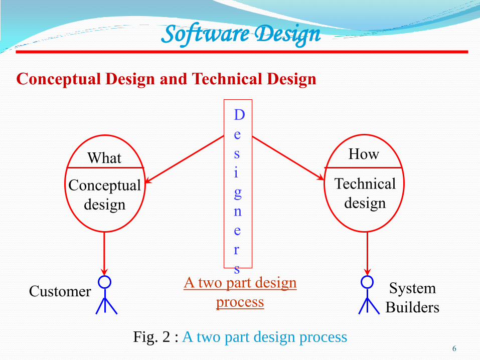
Fig. 2 : A two part design process
A two part design
process Customer System
Builders
How
Technical
design
D
e
s
i
g
n
e
r
s
What
Conceptual
design
Conceptual Design and Technical Design
Software Design

7
Software Design
Conceptual design answers :
Where will the data come from ?
What will happen to data in the system?
How will the system look to users?
What choices will be offered to users?
What is the timings of events?
How will the reports & screens look like?
8
Software Design
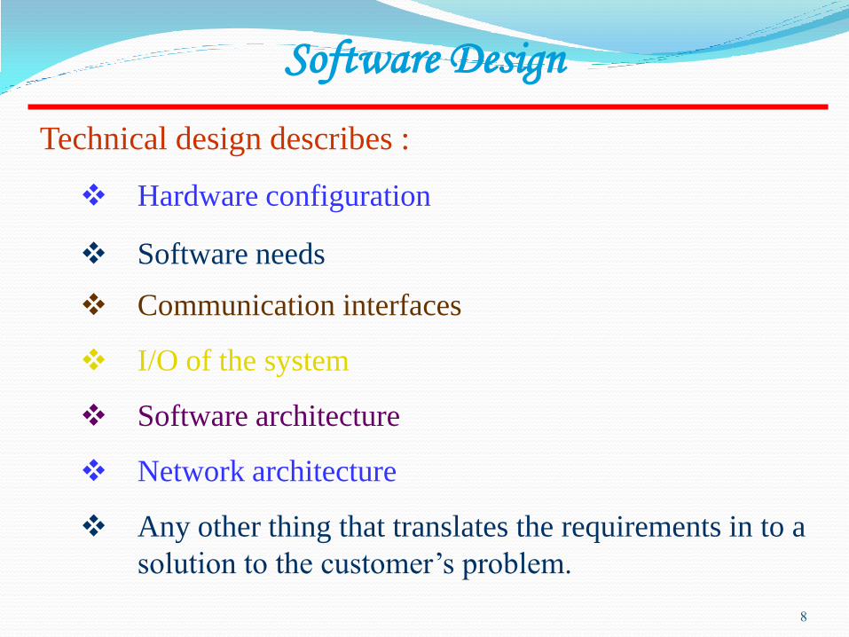
Technical design describes :
Hardware configuration
Software needs
Communication interfaces
I/O of the system
Software architecture
Network architecture
Any other thing that translates the requirements in to a
solution to the customer’s problem.

9
Software Design
The design needs to be
Correct & complete
Understandable
At the right level
Maintainable

10
Software Design
Informal
design
outline
Informal
design
More
formal
design
Finished
design
Fig. 3 : The transformation of an informal design to a detailed
design.

11
Software Design
MODULARITY
There are many definitions of the term module. Range is from :
i. Fortran subroutine
ii. Ada package
iii. Procedures & functions of PASCAL & C
iv. C++ / Java classes
v. Java packages
vi. Work assignment for an individual programmer
12
Software Design
All these definitions are correct. A modular
system consist of well defined manageable
units with well defined interfaces among
the units.

13
Software Design
Properties : i. Well defined subsystem ii. Well defined purpose iii. Can be separately compiled and stored in a
library. iv. Module can use other modules v. Module should be easier to use than to build vi. Simpler from outside than from the inside.
14
Software Design
Modularity is the single attribute of software that
allows a program to be intellectually manageable.
It enhances design clarity, which in turn eases
implementation, debugging, testing,
documenting, and maintenance of software
product.

15
16
Software Design
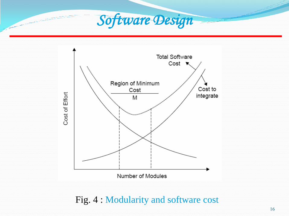
Fig. 4 : Modularity and software cost
17
Software Design
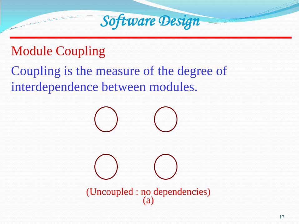
Module Coupling
(Uncoupled : no dependencies) (a)
Coupling is the measure of the degree of
interdependence between modules.

18
Software Design
Loosely coupled: some dependencies
(B)
Highly coupled: many dependencies
(C)
Fig. 5 : Module coupling
19
Software Design
This can be achieved as: Controlling the number of parameters passed
amongst modules. Avoid passing undesired data to calling
module. Maintain parent / child relationship between
calling & called modules. Pass data, not the control information.

20
Software Design
Consider the example of editing a student record in a
‘student information system’.
Edit student
record
Retrieve
student record
Student name,
student ID,
address, course
Student
record
EOF
Edit student
record
Retrieve
student record
Student
record
EOF
Student
ID
Poor design: Tight Coupling Good design: Loose Coupling
Fig. 6 : Example of coupling

21
Given two procedures A & B, we can identify number of
ways in which they can be coupled.
Data coupling Best
Stamp coupling
Control coupling
External coupling
Common coupling
Content coupling Worst
Fig. 7 : The types of module coupling
Software Design

22
Software Design
Data coupling
Stamp coupling
The dependency between module A and B is said to be data
coupled if their dependency is based on the fact they
communicate by only passing of data. Other than
communicating through data, the two modules are
independent.
Stamp coupling occurs between module A and B when
complete data structure is passed from one module to another.

23
Software Design
Control coupling
Module A and B are said to be control coupled if they
communicate by passing of control information. This is usually
accomplished by means of flags that are set by one module and
reacted upon by the dependent module.
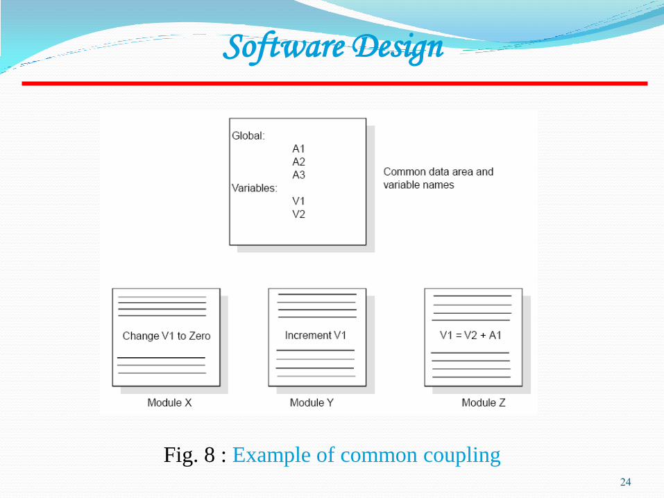
Common coupling
With common coupling, module A and module B have shared
data. Global data areas are commonly found in programming
languages. Making a change to the common data means tracing
back to all the modules which access that data to evaluate the
effect of changes.
24
Fig. 8 : Example of common coupling
Software Design
25
Software Design
Content coupling
Content coupling occurs when module A changes data of
module B or when control is passed from one module to the
middle of another. In Fig. 9, module B branches into D, even
though D is supposed to be under the control of C.

26
Fig. 9 : Example of content coupling
Software Design

27
Cohesion is a measure of the degree to which the
elements of a module are functionally related.
Software Design
Module Cohesion
Fig. 10 : Cohesion=Strength of relations within modules
Module strength
28
Software Design
Types of cohesion
Functional cohesion
Sequential cohesion
Procedural cohesion
Temporal cohesion
Logical cohesion
Coincident cohesion

29
Fig. 11 : Types of module cohesion
Software Design
Functional Cohesion Best (high)
Sequential Cohesion
Communicational Cohesion
Procedural Cohesion
Temporal Cohesion
Logical Cohesion
Coincidental Cohesion Worst (low)

30
Software Design
Functional Cohesion
A and B are part of a single functional task. This is very good reason
for them to be contained in the same procedure.
Sequential Cohesion Module A outputs some data which forms the input to B. This is the
reason for them to be contained in the same procedure.
31
Software Design
Procedural Cohesion
Procedural Cohesion occurs in modules whose instructions although
accomplish different tasks yet have been combined because there
is a specific order in which the tasks are to be completed.
Temporal Cohesion Module exhibits temporal cohesion when it contains tasks that are
related by the fact that all tasks must be executed in the same
time-span.
32
Software Design
Logical Cohesion
Logical cohesion occurs in modules that contain instructions that
appear to be related because they fall into the same logical class
of functions.
Coincidental Cohesion Coincidental cohesion exists in modules that contain instructions
that have little or no relationship to one another.

33
Software Design
Relationship between Cohesion & Coupling
Fig. 12 : View of cohesion and coupling
If the software is not properly modularized, a host of seemingly
trivial enhancement or changes will result into death of the project.
Therefore, a software engineer must design the modules with goal of
high cohesion and low coupling.

34
Software Design
STRATEGY OF DESIGN
A good system design strategy is to organize the program modules
in such a way that are easy to develop and latter to, change.
Structured design techniques help developers to deal with the size
and complexity of programs. Analysts create instructions for the
developers about how code should be written and how pieces of
code should fit together to form a program. It is important for two
reasons:
First, even pre-existing code, if any, needs to be understood,
organized and pieced together.
Second, it is still common for the project team to have to write
some code and produce original programs that support the
application logic of the system.

35
Bottom-Up Design
Fig. 13 : Bottom-up tree structure
These modules are collected together in the form of a “library”.
Software Design
36
Top-Down Design
A top down design approach starts by identifying the major modules
of the system, decomposing them into their lower level modules and
iterating until the desired level of detail is achieved. This is stepwise
refinement; starting from an abstract design, in each step the design
is refined to a more concrete level, until we reach a level where no
more refinement is needed and the design can be implemented
directly.
Software Design
37
Hybrid Design
For top-down approach to be effective, some bottom-up approach is
essential for the following reasons:
Software Design
To permit common sub modules.
Near the bottom of the hierarchy, where the intuition is simpler, and
the need for bottom-up testing is greater, because there are more
number of modules at low levels than high levels.
In the use of pre-written library modules, in particular, reuse of
modules.
38
FUNCTION ORIENTED DESIGN
Function Oriented design is an approach to software design where
the design is decomposed into a set of interacting units where each
unit has a clearly defined function. Thus, system is designed from
a functional viewpoint.
Software Design
Assignment Explain various types of software designs
Difference b/t Cohesion & Coupling
39
Research A Coupling and Cohesion Metrics Suite for
Object-Oriented Software
40

41

42
Software Design
43
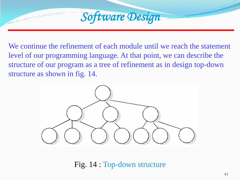
We continue the refinement of each module until we reach the statement
level of our programming language. At that point, we can describe the
structure of our program as a tree of refinement as in design top-down
structure as shown in fig. 14.
Software Design
Fig. 14 : Top-down structure
44
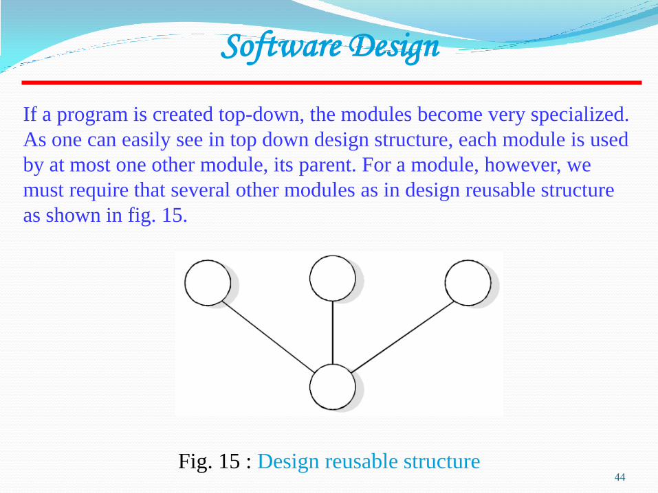
If a program is created top-down, the modules become very specialized.
As one can easily see in top down design structure, each module is used
by at most one other module, its parent. For a module, however, we
must require that several other modules as in design reusable structure
as shown in fig. 15.
Software Design
Fig. 15 : Design reusable structure

45
Design Notations
Design notations are largely meant to be used during the process of
design and are used to represent design or design decisions. For a
function oriented design, the design can be represented graphically
or mathematically by the following:
Software Design
Data flow diagrams
Data Dictionaries
Structure Charts
Pseudocode

46
Structure Chart
It partition a system into block boxes. A black box means that
functionality is known to the user without the knowledge of internal
design.
Software Design
Fig. 16 : Hierarchical format of a structure chart
47
Software Design
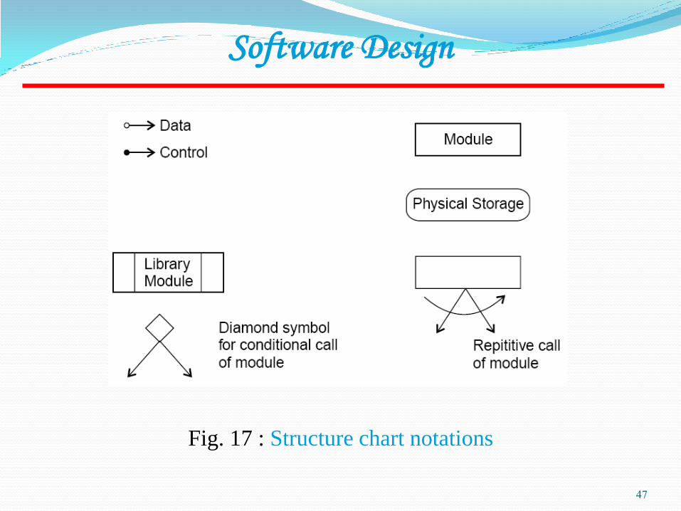
Fig. 17 : Structure chart notations

48
Software Design
Fig. 18 : Update file
A structure chart for “update file” is given in fig. 18.
49
Software Design
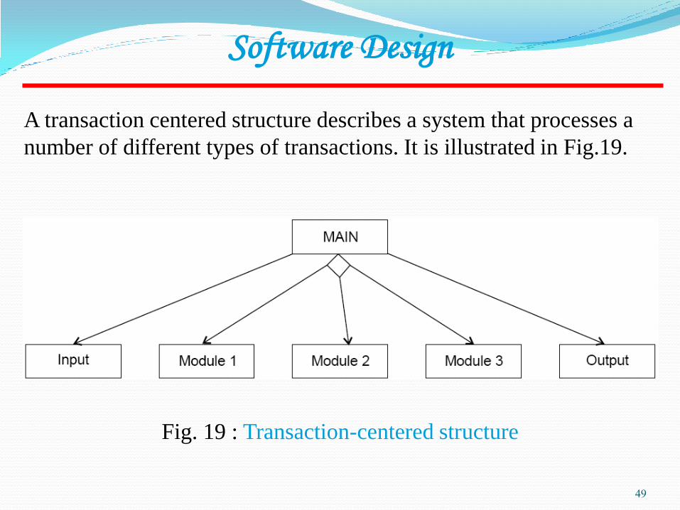
Fig. 19 : Transaction-centered structure
A transaction centered structure describes a system that processes a
number of different types of transactions. It is illustrated in Fig.19.
50
In the above figure the MAIN module controls the system operation
its functions is to:
Software Design
invoke the INPUT module to read a transaction;
determine the kind of transaction and select one of a number of
transaction modules to process that transaction, and
output the results of the processing by calling OUTPUT module.

51
Pseudocode
Pseudocode notation can be used in both the preliminary and detailed
design phases.
Software Design
Using pseudocode, the designer describes system characteristics
using short, concise, English language phrases that are structured by
key words such as It-Then-Else, While-Do, and End.

52
Functional Procedure Layers
Software Design
Function are built in layers, Additional notation is used to specify
details.
Level 0
Function or procedure name
Relationship to other system components (e.g., part of
which system, called by which routines, etc.)
Brief description of the function purpose.
Author, date

53
Software Design
Level 1
Function Parameters (problem variables, types, purpose,
etc.)
Global variables (problem variable, type, purpose,
sharing information)
Routines called by the function
Side effects
Input/Output Assertions

54
Software Design
Level 2
Local data structures (variable etc.)
Timing constraints
Exception handling (conditions, responses, events)
Any other limitations
Level 3
Body (structured chart, English pseudo code, decision
tables, flow charts, etc.)
55
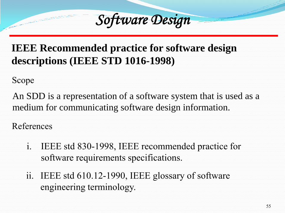
IEEE Recommended practice for software design
descriptions (IEEE STD 1016-1998)
An SDD is a representation of a software system that is used as a
medium for communicating software design information.
Software Design
Scope
References
i. IEEE std 830-1998, IEEE recommended practice for
software requirements specifications.
ii. IEEE std 610.12-1990, IEEE glossary of software
engineering terminology.
56
Software Design
Definitions
i. Design entity. An element (Component) of a design that is
structurally and functionally distinct from other elements and
that is separately named and referenced.
ii. Design View. A subset of design entity attribute information
that is specifically suited to the needs of a software project
activity.
iii. Entity attributes. A named property or characteristics of a
design entity. It provides a statement of fact about the entity.
iv. Software design description (SDD). A representation of a
software system created to facilitate analysis, planning,
implementation and decision making.
57
The SDD shows how the software system will be structured to
satisfy the requirements identified in the SRS. It is basically the
translation of requirements into a description of the software
structure, software components, interfaces, and data necessary for
the implementation phase. Hence, SDD becomes the blue print for
the implementation activity.
Software Design
Purpose of an SDD
Design Description Information Content
Introduction
Design entities
Design entity attributes
58
a) Identification
b) Type
c) Purpose
d) Function
e) Subordinates
f) Dependencies
Software Design
The attributes and associated information items are defined in the
following subsections:
g) Interface
h) Resources
i) Processing
j) Data
59
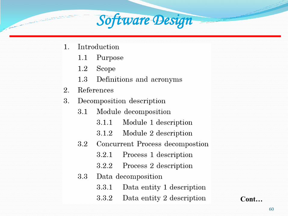
Each design description writer may have a different view of what are
considered the essential aspects of a software design. The
organization of SDD is given in table 1. This is one of the possible
ways to organize and format the SDD.
Software Design
Design Description Organization
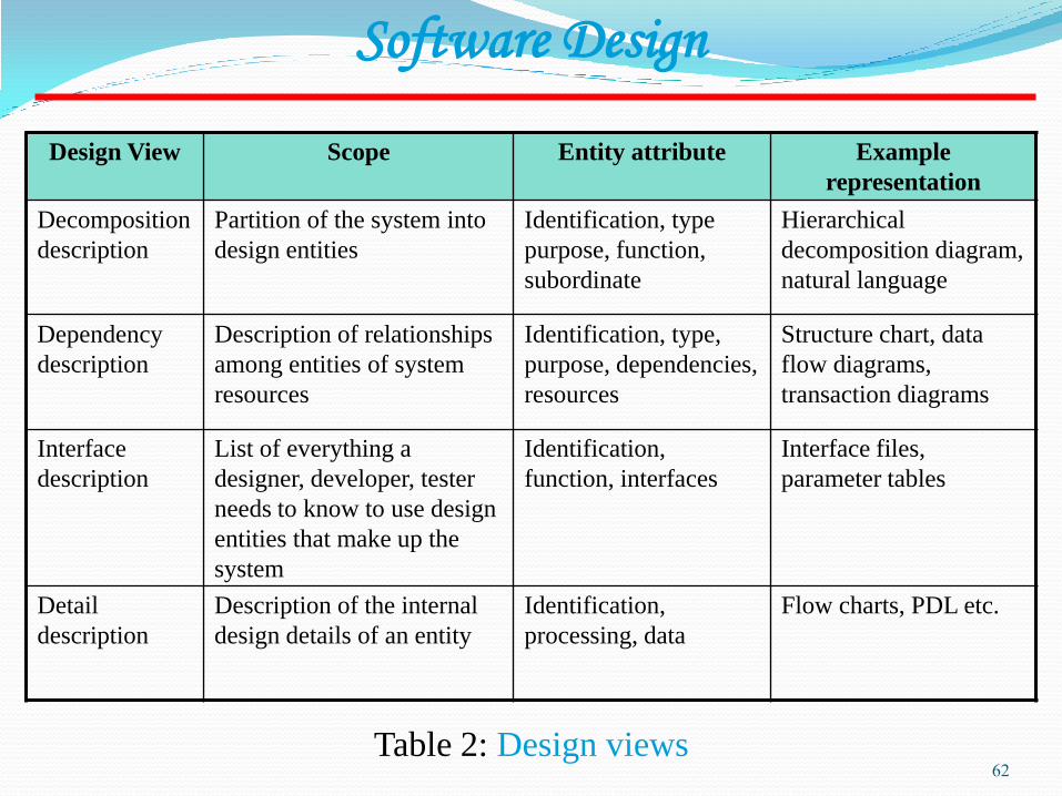
A recommended organization of the SDD into separate design views
to facilitate information access and assimilation is given in table 2.
60
Software Design
Cont…
61
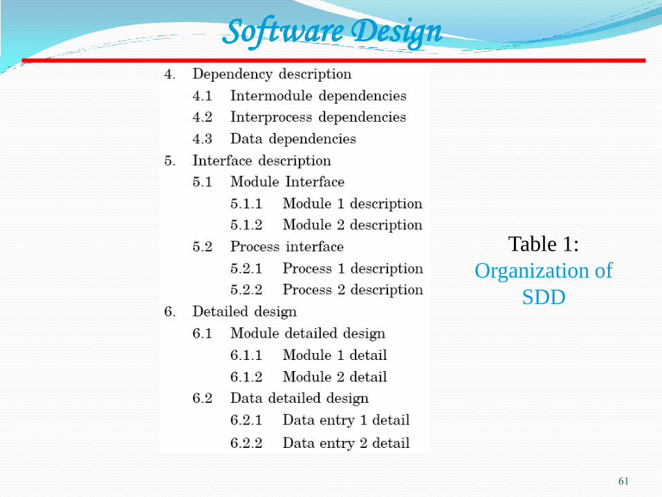
Software Design
Table 1:
Organization of
SDD
62
Software Design
Table 2: Design views
Design View Scope Entity attribute Example
representation
Decomposition
description
Partition of the system into
design entities
Identification, type
purpose, function,
subordinate
Hierarchical
decomposition diagram,
natural language
Dependency
description
Description of relationships
among entities of system
resources
Identification, type,
purpose, dependencies,
resources
Structure chart, data
flow diagrams,
transaction diagrams
Interface
description
List of everything a
designer, developer, tester
needs to know to use design
entities that make up the
system
Identification,
function, interfaces
Interface files,
parameter tables
Detail
description
Description of the internal
design details of an entity
Identification,
processing, data
Flow charts, PDL etc.
63
Object Oriented Design
Object oriented design is the result of focusing attention not on the
function performed by the program, but instead on the data that are
to do manipulated by the program. Thus, it is orthogonal to function
oriented design.
Software Design
Object Oriented Design begins with an examination of the real
world “things” that are part of the problem to be solved. These
things (which we will call objects) are characterized individually in
terms of their attributes and behavior.

64
Object Oriented Design is not dependent on any specific implementation
language. Problems are modeled using objects. Objects have:
Software Design
Basic Concepts
Behavior (they do things)
State (which changes when they do things)
65
i. Objects
Software Design
The various terms related to object design are:
The word “Object” is used very frequently and conveys different meaning in
different circumstances. Here, meaning is an entity able to save a state
(information) and which offers a number of operations (behavior) to either
examine or affect this state. An object is characterized by number of
operations and a state which remembers the effect of these operations.
66
Software Design
Objects communicate by message passing. Messages consist of the identity of
the target object, the name of the requested operation and any other operation
needed to perform the function. Message are often implemented as procedure
or function calls.
ii. Messages
iii. Abstraction
In object oriented design, complexity is managed using abstraction.
Abstraction is the elimination of the irrelevant and the amplification of the
essentials.

67
Software Design
In any system, there shall be number of objects. Some of the objects may have
common characteristics and we can group the objects according to these
characteristics. This type of grouping is known as a class. Hence, a class is a
set of objects that share a common structure and a common behavior.
iv. Class
We may define a class “car” and each object that represent a car becomes an
instance of this class. In this class “car”, Indica, Santro, Maruti, Indigo are
instances of this class as shown in fig. 20.
Classes are useful because they act as a blueprint for objects. If we want a
new square we may use the square class and simply fill in the particular
details (i.e. colour and position) fig. 21 shows how can we represent the
square class.

68
Software Design
Fig.20: Indica, Santro, Maruti, Indigo are all instances of the class
“car”

69
Software Design
Fig. 21: The square class

70
Software Design
An attributes is a data value held by the objects in a class. The square class has
two attributes: a colour and array of points. Each attributes has a value for
each object instance. The attributes are shown as second part of the class as
shown in fig. 21.
v. Attributes
An operation is a function or transformation that may be applied to or by
objects in a class. In the square class, we have two operations: set colour() and
draw(). All objects in a class share the same operations. An object “knows” its
class, and hence the right implementation of the operation. Operation are
shown in the third part of the class as indicated in fig. 21.
vi. Operations
71
Software Design
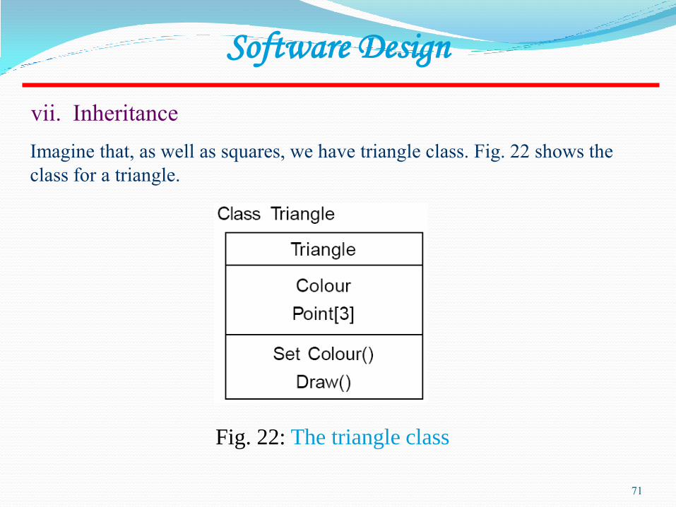
Imagine that, as well as squares, we have triangle class. Fig. 22 shows the
class for a triangle.
vii. Inheritance
Fig. 22: The triangle class

72
Software Design
Now, comparing fig. 21 and 22, we can see that there is some difference
between triangle and squares classes.
For example, at a high level of abstraction, we might want to think of a picture
as made up of shapes and to draw the picture, we draw each shape in turn. We
want to eliminate the irrelevant details: we do not care that one shape is a
square and the other is a triangle as long as both can draw themselves.
To do this, we consider the important parts out of these classes in to a new
class called Shape. Fig. 23 shows the results.

73
Software Design
Fig. 23: Abstracting common features in a new class
This sort of abstraction is called inheritance. The low level classes (known as
subclasses or derived classes) inherit state and behavior from this high level
class (known as a super class or base class).

74
Software Design
When we abstract just the interface of an operation and leave the
implementation to subclasses it is called a polymorphic operation and process
is called polymorphism.
Encapsulation is also commonly referred to as “Information Hiding”. It
consists of the separation of the external aspects of an object from the internal
implementation details of the object.
viii. Polymorphism
ix. Encapsulation (Information Hiding)
x. Hierarchy
Hierarchy involves organizing something according to some particular order
or rank. It is another mechanism for reducing the complexity of software by
being able to treat and express sub-types in a generic way.

75

76
Software Design
Fig. 24: Hierarchy
77
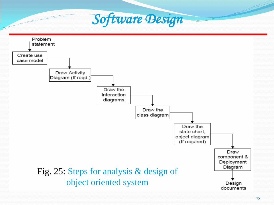
There are various steps in the analysis and design of an object oriented system
and are given in fig. 25
Software Design
Steps to Analyze and Design Object Oriented System
78
Software Design
Fig. 25: Steps for analysis & design of
object oriented system
79
i. Create use case model
Software Design
First step is to identify the actors interacting with the system. We should then
write the use case and draw the use case diagram.
Activity Diagram illustrate the dynamic nature of a system by modeling the
flow of control form activity to activity. An activity represents an operation on
some class in the system that results in a change in the state of the system. Fig.
26 shows the activity diagram processing an order to deliver some goods.
ii. Draw activity diagram (If required)

80
Software Design
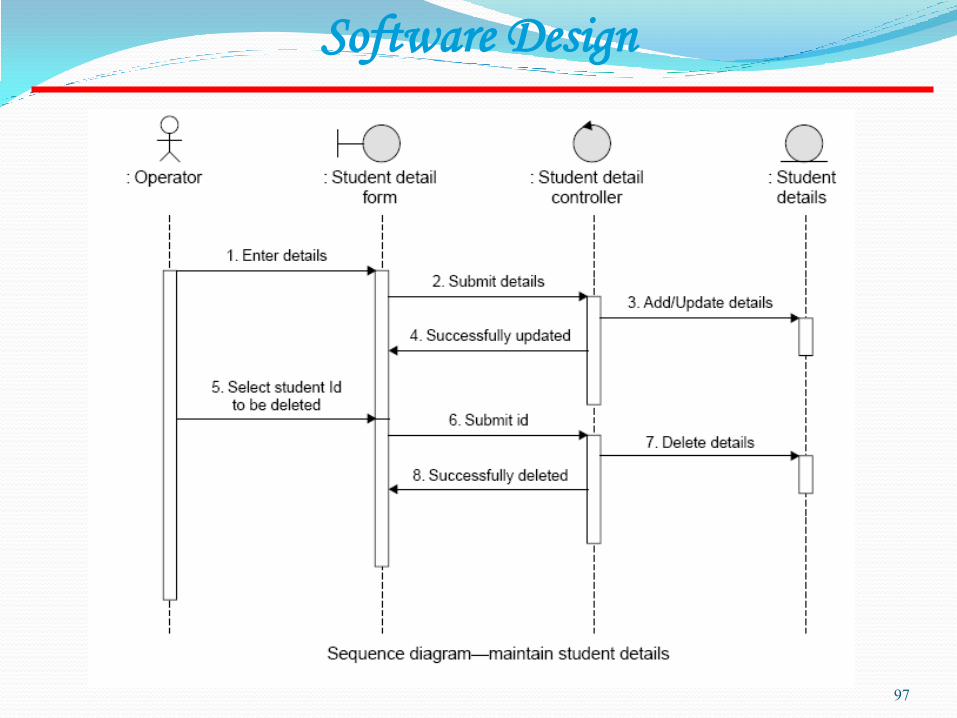
iii. Draw the interaction diagram
An interaction diagram shows an interaction, consisting of a set of objects and
their relationship, including the messages that may be dispatched among them.
Interaction diagrams address the dynamic view of a system.
a) Firstly, we should identify that the objects with respects to every use
case.
b) We draw the sequence diagrams for every use case.
d) We draw the collaboration diagrams for every use case.
Steps to draws interaction diagrams are as under:

81
Software Design
The object types used in this analysis model are entity objects, interface
objects and control objects as given in fig. 27.
Fig. 27: Object types

82
Software Design
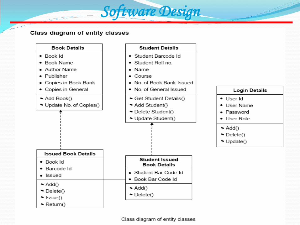
The class diagram shows the relationship amongst classes. There are four
types of relationships in class diagrams.
iv. Draw the class diagram
a) Association are semantic connection between classes. When an
association connects two classes, each class can send messages
to the other in a sequence or a collaboration diagram.
Associations can be bi-directional or unidirectional.

83
Software Design
b) Dependencies connect two classes. Dependencies are always
unidirectional and show that one class, depends on the
definitions in another class.
c) Aggregations are stronger form of association. An aggregation
is a relationship between a whole and its parts.
d) Generalizations are used to show an inheritance relationship
between two classes.

84
Software Design
A state chart diagram is used to show the state space of a given class, the
event that cause a transition from one state to another, and the action that
result from a state change. A state transition diagram for a “book” in the
library system is given in fig. 28.
v. Design of state chart diagrams
Fig. 28: Transition chart for “book” in a library system.

85
Software Design
Component diagrams address the static implementation view of a system they
are related to class diagrams in that a component typically maps to one or
more classes, interfaces or collaboration.
vi. Draw component and development diagram
Deployment Diagram Captures relationship between physical components and
the hardware.

86
Software Design
A software has to be developed for automating the manual library of a
University. The system should be stand alone in nature. It should be designed
to provide functionality’s as explained below:
Issue of Books:
A student of any course should be able to get books issued.
Books from General Section are issued to all but Book bank books are
issued only for their respective courses.
A limitation is imposed on the number of books a student can issue.
A maximum of 4 books from Book bank and 3 books from General
section is issued for 15 days only.The software takes the current
system date as the date of issue and calculates date of return.
87
Software Design
A bar code detector is used to save the student as well as book
information.
The due date for return of the book is stamped on the book.
Return of Books:
Any person can return the issued books.
The student information is displayed using the bar code detector.
The system displays the student details on whose name the books
were issued as well as the date of issue and return of the book.
The system operator verifies the duration for the issue.
The information is saved and the corresponding updating take place in
the database.
88
Software Design
Query Processing:
The system should be able to provide information like:
Availability of a particular book.
Availability of book of any particular author.
Number of copies available of the desired book.
The system should also be able to generate reports regarding the details of
the books available in the library at any given time. The corresponding
printouts for each entry (issue/return) made in the system should be
generated. Security provisions like the ‘login authenticity should be
provided. Each user should have a user id and a password. Record of the
users of the system should be kept in the log file. Provision should be made
for full backup of the system.

89
Software Design
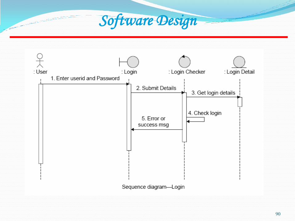
90
Software Design

91
Software Design
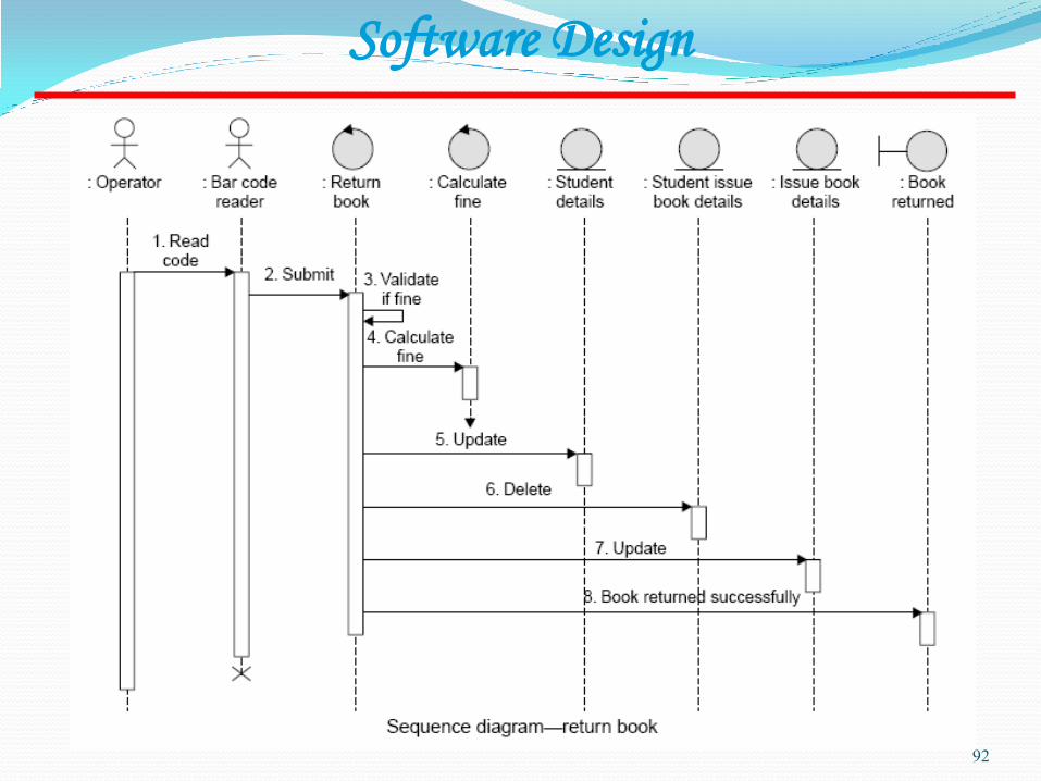
92
Software Design
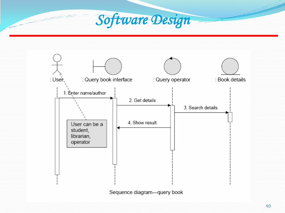
93
Software Design

94
Software Design

95
Software Design
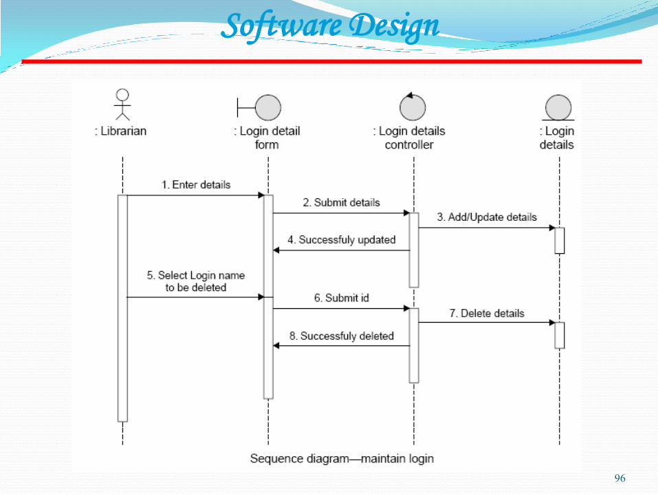
96
Software Design
97
Software Design
98
Software Design
Architectural Design
99
Lecture – 19

Objectives To introduce architectural design and to discuss its
importance
To explain the architectural design decisions that have to be made
To introduce three complementary architectural styles covering organisation, decomposition and control
To discuss reference architectures are used to communicate and compare architectures
100
Topics covered Architectural design decisions
System organisation
Decomposition styles
Control styles
Reference architectures
101

Software architecture The design process for identifying the sub-systems
making up a system and the framework for sub-system control and communication is architectural design.
The output of this design process is a description of the software architecture.
102
Architectural design An early stage of the system design process.
Represents the link between specification and design processes.
Often carried out in parallel with some specification activities.
It involves identifying major system components and their communications.
103
Advantages of explicit architecture Stakeholder communication
Architecture may be used as a focus of discussion by system stakeholders.
System analysis Means that analysis of whether the system can meet its
non-functional requirements is possible.
Large-scale reuse The architecture may be reusable across a range of
systems.
104

Architecture and system characteristics
Performance Localise critical operations and minimise communications. Use
large rather than fine-grain components.
Security Use a layered architecture with critical assets in the inner layers.
Safety Localise safety-critical features in a small number of sub-systems.
Availability Include redundant components and mechanisms for fault
tolerance.
Maintainability Use fine-grain, replaceable components.
105
Architectural conflicts Using large-grain components improves performance
but reduces maintainability.
Introducing redundant data improves availability but makes security more difficult.
Localising safety-related features usually means more communication so degraded performance.
106

System structuring Concerned with decomposing the system into
interacting sub-systems.
The architectural design is normally expressed as a block diagram presenting an overview of the system structure.
More specific models showing how sub-systems share data, are distributed and interface with each other may also be developed.
107
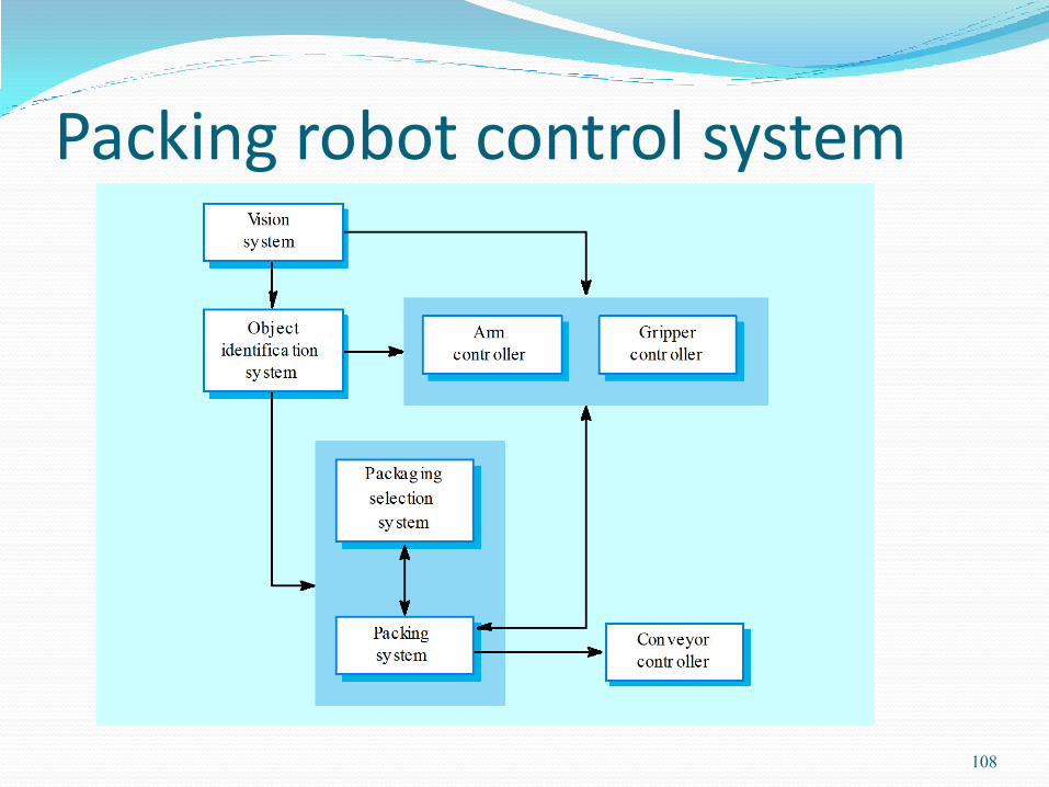
Packing robot control system
108

Box and line diagrams Very abstract - they do not show the nature of
component relationships nor the externally visible properties of the sub-systems.
However, useful for communication with stakeholders and for project planning.
109

Architectural design decisions Architectural design is a creative process so the process
differs depending on the type of system being developed.
However, a number of common decisions span all design processes.
110
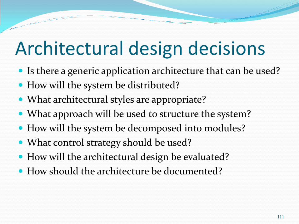
Architectural design decisions Is there a generic application architecture that can be used?
How will the system be distributed?
What architectural styles are appropriate?
What approach will be used to structure the system?
How will the system be decomposed into modules?
What control strategy should be used?
How will the architectural design be evaluated?
How should the architecture be documented?
111
Architecture reuse Systems in the same domain often have similar
architectures that reflect domain concepts.
Application product lines are built around a core architecture with variants that satisfy particular customer requirements.
Application architectures are covered in Chapter 13 and product lines in Chapter 18.
112
Architectural styles The architectural model of a system may conform to a
generic architectural model or style.
An awareness of these styles can simplify the problem of defining system architectures.
However, most large systems are heterogeneous and do not follow a single architectural style.
113

Architectural models Used to document an architectural design.
Static structural model that shows the major system components.
Dynamic process model that shows the process structure of the system.
Interface model that defines sub-system interfaces.
Relationships model such as a data-flow model that shows sub-system relationships.
Distribution model that shows how sub-systems are distributed across computers.
114

System organisation Reflects the basic strategy that is used to structure a
system.
Three organisational styles are widely used:
A shared data repository style;
A shared services and servers style;
An abstract machine or layered style.
115

116

117

The repository model Sub-systems must exchange data. This may be done in
two ways: Shared data is held in a central database or repository
and may be accessed by all sub-systems;
Each sub-system maintains its own database and passes data explicitly to other sub-systems.
When large amounts of data are to be shared, the repository model of sharing is most commonly used.
118

CASE toolset architecture
119

Repository model characteristics Advantages
Efficient way to share large amounts of data;
Sub-systems need not be concerned with how data is produced Centralised management e.g. backup, security, etc.
Sharing model is published as the repository schema.
Disadvantages Sub-systems must agree on a repository data model. Inevitably a
compromise;
Data evolution is difficult and expensive;
No scope for specific management policies;
Difficult to distribute efficiently.
120

Client-server model Distributed system model which shows how data and
processing is distributed across a range of components.
Set of stand-alone servers which provide specific services such as printing, data management, etc.
Set of clients which call on these services.
Network which allows clients to access servers.
121

Film and picture library
122

Client-server characteristics Advantages
Distribution of data is straightforward;
Makes effective use of networked systems. May require cheaper hardware;
Easy to add new servers or upgrade existing servers.
Disadvantages No shared data model so sub-systems use different data
organisation. Data interchange may be inefficient;
Redundant management in each server;
No central register of names and services - it may be hard to find out what servers and services are available.
123

Abstract machine (layered) model Used to model the interfacing of sub-systems.
Organises the system into a set of layers (or abstract machines) each of which provide a set of services.
Supports the incremental development of sub-systems in different layers. When a layer interface changes, only the adjacent layer is affected.
However, often artificial to structure systems in this way.
124
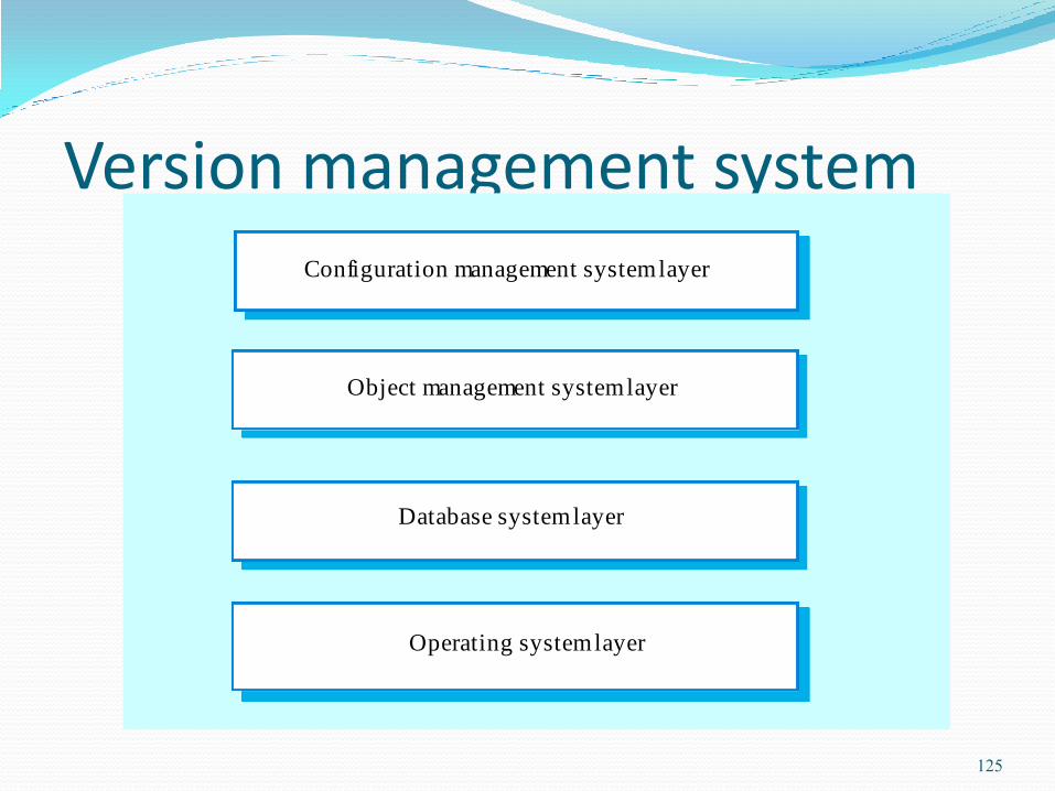
Version management system Configuration management system layer
Database system layer
Operating system layer
Object management system layer
125
Modular decomposition styles Styles of decomposing sub-systems into modules.
No rigid distinction between system organisation and modular decomposition.
126

Sub-systems and modules A sub-system is a system in its own right whose
operation is independent of the services provided by other sub-systems.
A module is a system component that provides services to other components but would not normally be considered as a separate system.
127
Modular decomposition Another structural level where sub-systems are
decomposed into modules.
Two modular decomposition models covered An object model where the system is decomposed into interacting
object;
A pipeline or data-flow model where the system is decomposed into functional modules which transform inputs to outputs.
If possible, decisions about concurrency should be delayed until modules are implemented.
128

Object models Structure the system into a set of loosely coupled
objects with well-defined interfaces.
Object-oriented decomposition is concerned with identifying object classes, their attributes and operations.
When implemented, objects are created from these classes and some control model used to coordinate object operations.
129
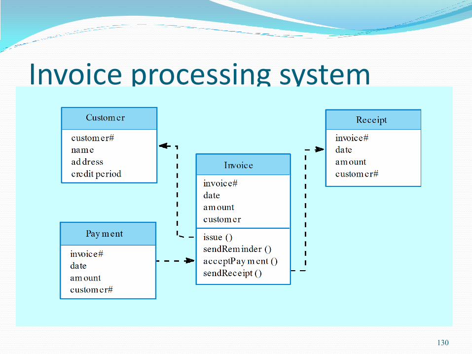
Invoice processing system
130

Object model advantages Objects are loosely coupled so their implementation
can be modified without affecting other objects.
The objects may reflect real-world entities.
OO implementation languages are widely used.
However, object interface changes may cause problems and complex entities may be hard to represent as objects.
131

Architectural models Different architectural models may be produced
during the design process
Each model presents different perspectives on the architecture
132

Architecture attributes Performance
Localise operations to minimise sub-system communication
Security Use a layered architecture with critical assets in inner layers
Safety Isolate safety-critical components
Availability Include redundant components in the architecture
Maintainability Use fine-grain, self-contained components
133

Object-oriented Design
134
Lecture – 20

Objectives To explain how a software design may be represented
as a set of interacting objects that manage their own state and operations
To describe the activities in the object-oriented design process
To introduce various models that can be used to describe an object-oriented design
To show how the UML may be used to represent these models
135
Topics covered Objects and object classes
An object-oriented design process
Design evolution
136
Object-oriented development Object-oriented analysis, design and programming are
related but distinct.
OOA is concerned with developing an object model of the application domain.
OOD is concerned with developing an object-oriented system model to implement requirements.
OOP is concerned with realising an OOD using an OO programming language such as Java or C++.
137
Characteristics of OOD Objects are abstractions of real-world or system entities
and manage themselves.
Objects are independent and encapsulate state and representation information.
System functionality is expressed in terms of object services.
Shared data areas are eliminated. Objects communicate by message passing.
Objects may be distributed and may execute sequentially or in parallel.
138

Interacting objects
139

Advantages of OOD Easier maintenance. Objects may be
understood as stand-alone entities.
Objects are potentially reusable components.
For some systems, there may be an obvious mapping from real world entities to system objects.
140

Objects and object classes Objects are entities in a software system which
represent instances of real-world and system entities.
Object classes are templates for objects. They may be used to create objects.
Object classes may inherit attributes and services from other object classes.
141
Objects and object classes An object is an entity that has a state and a defined set of
operations which operate on that state. The state is represented as a
set of object attributes. The operations associated with the object
provide services to other objects (clients) which request these
services when some computation is required.
Objects are created according to some object class definition. An
object class definition serves as a template for objects. It includes
declarations of all the attributes and services which should be
associated with an object of that class.
142
The Unified Modeling Language Several different notations for describing object-oriented
designs were proposed in the 1980s and 1990s.
The Unified Modeling Language is an integration of these notations.
It describes notations for a number of different models that may be produced during OO analysis and design.
It is now a de facto standard for OO modelling.
143
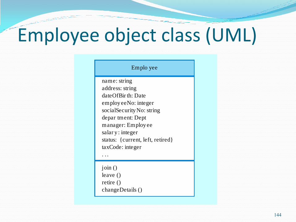
Employee object class (UML)
Emplo yee
name: string
address: string
dateOfBir th: Date
employ eeNo: integer
socialSecurity No: string
depar tment: Dept
manager: Employ ee
salar y : integer
status: {current, left, retired}
taxCode: integer
. . .
join ()
leave ()
retire ()
changeDetails ()
144
Object communication Conceptually, objects communicate by
message passing.
Messages The name of the service requested by the calling object;
Copies of the information required to execute the service and the name of a holder for the result of the service.
In practice, messages are often implemented by procedure calls Name = procedure name;
Information = parameter list.
145
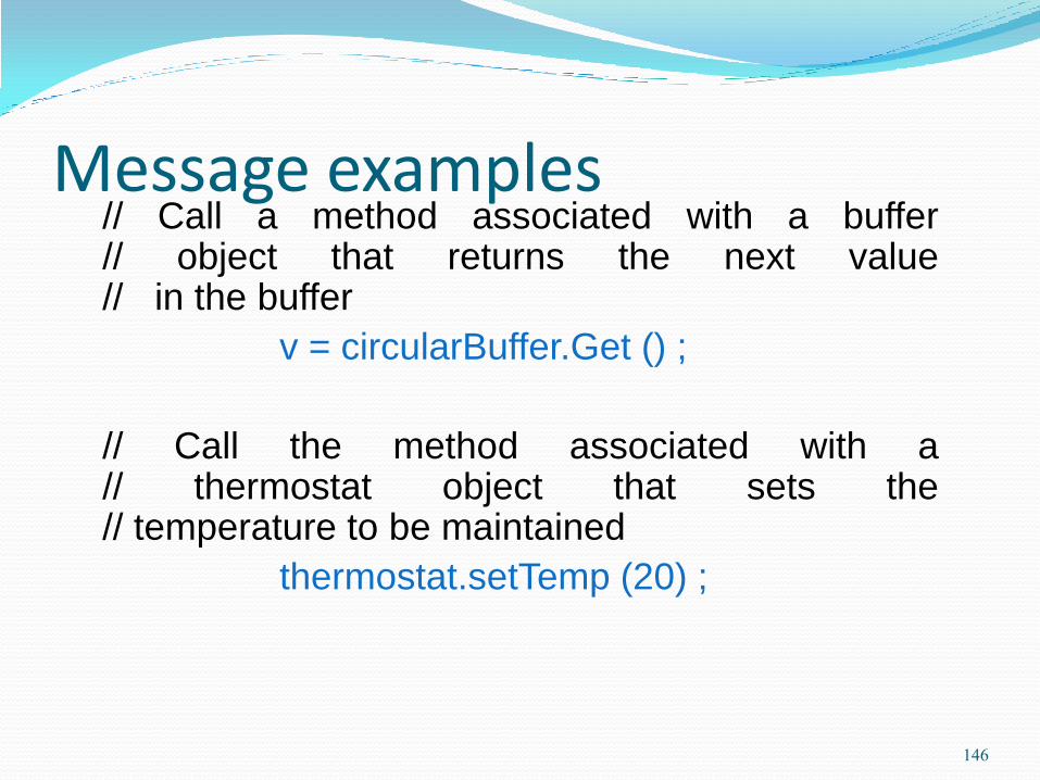
Message examples // Call a method associated with a buffer
// object that returns the next value // in the buffer
v = circularBuffer.Get () ;
// Call the method associated with a // thermostat object that sets the // temperature to be maintained
thermostat.setTemp (20) ;
146

Generalisation and inheritance Objects are members of classes that define
attribute types and operations.
Classes may be arranged in a class hierarchy where one class (a super-class) is a generalisation of one or more other classes (sub-classes).
A sub-class inherits the attributes and operations from its super class and may add new methods or attributes of its own.
Generalisation in the UML is implemented as inheritance in OO programming languages.
147
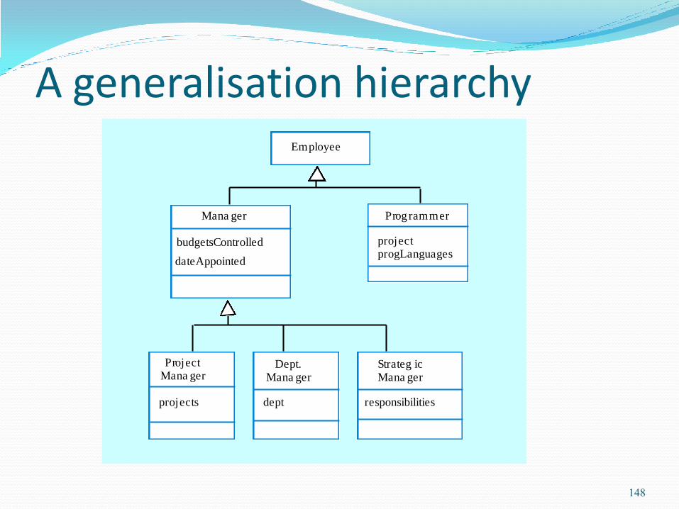
A generalisation hierarchy Employee
Prog rammer
projectprogLanguages
Mana ger
ProjectMana ger
budgetsControlled
dateAppointed
projects
Dept.Mana ger
Strateg icMana ger
dept responsibilities
148

Advantages of inheritance It is an abstraction mechanism which may be used to
classify entities.
It is a reuse mechanism at both the design and the programming level.
The inheritance graph is a source of organisational knowledge about domains and systems.
149
Problems with inheritance Object classes are not self-contained. they cannot be
understood without reference to their super-classes.
Designers have a tendency to reuse the inheritance graph created during analysis. Can lead to significant inefficiency.
The inheritance graphs of analysis, design and implementation have different functions and should be separately maintained.
150

UML associations Objects and object classes participate in relationships with
other objects and object classes.
In the UML, a generalised relationship is indicated by an association.
Associations may be annotated with information that describes the association.
Associations are general but may indicate that an attribute of an object is an associated object or that a method relies on an associated object.
151

An association model
Employee Depar tment
Manager
is-member-of
is-managed-by
manages
152

Concurrent objects The nature of objects as self-contained entities make
them suitable for concurrent implementation.
The message-passing model of object communication can be implemented directly if objects are running on separate processors in a distributed system.
153

Servers and active objects Servers.
The object is implemented as a parallel process (server) with entry points corresponding to object operations. If no calls are made to it, the object suspends itself and waits for further requests for service.
Active objects Objects are implemented as parallel processes and the
internal object state may be changed by the object itself and not simply by external calls.
154

Active transponder object Active objects may have their attributes modified by
operations but may also update them autonomously using internal operations.
A Transponder object broadcasts an aircraft’s position. The position may be updated using a satellite positioning system. The object periodically update the position by triangulation from satellites.
155
An object-oriented design process Structured design processes involve developing a
number of different system models.
They require a lot of effort for development and maintenance of these models and, for small systems, this may not be cost-effective.
However, for large systems developed by different groups design models are an essential communication mechanism.
156

Process stages Highlights key activities without being tied to any
proprietary process such as the RUP.
Define the context and modes of use of the system;
Design the system architecture;
Identify the principal system objects;
Develop design models;
Specify object interfaces.
157
Weather system description A weather mapping system is required to generate weather maps on a
regular basis using data collected from remote, unattended weather stations
and other data sources such as weather observers, balloons and satellites.
Weather stations transmit their data to the area computer in response to a
request from that machine.
The area computer system validates the collected data and integrates it with
the data from different sources. The integrated data is archived and, using
data from this archive and a digitised map database a set of local weather
maps is created. Maps may be printed for distribution on a special-purpose
map printer or may be displayed in a number of different formats.
158
System context and models of use Develop an understanding of the relationships between the
software being designed and its external environment
System context A static model that describes other systems in the environment. Use
a subsystem model to show other systems. Following slide shows the systems around the weather station system.
Model of system use A dynamic model that describes how the system interacts with its
environment. Use use-cases to show interactions
159
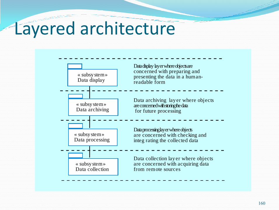
Layered architecture
« subsystem»Data collection
« subsystem»Data processing
« subsystem»Data archiving
« subsystem»Data display
Data collection layer where objectsare concerned with acquiring datafrom remote sources
Data processing layer where objectsare concerned with checking andinteg rating the collected data
Data archiving layer where objectsare concerned with storing the data for future processing
Data display layer where objects areconcerned with preparing andpresenting the data in a human-readable form
160

Subsystems in the weather mapping system
Datastorage
Userinter face
« subsystem»Data collection
« subsystem»Data processing
« subsystem»Data archiving
« subsystem»Data display
Weatherstation
Satellite
Comms
Balloon
Observer
Map store Data store
Datastorage
Map
Userinter face
Mapdisplay
Mapprinter
Datachecking
Datainteg ration
161
Use-case models Use-case models are used to represent each interaction
with the system.
A use-case model shows the system features as ellipses and the interacting entity as a stick figure.
162
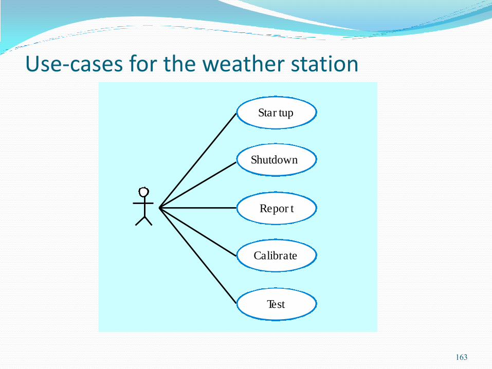
Use-cases for the weather station
Star tup
Shutdown
Repor t
Calibrate
Test
163

Use-case description System Weather station
Use-case Report
Actors Weather data collection system, Weather station
Data The weather station sends a summary of the weather data that has been
collected from the instruments in the collection period to the weather data
collection system. The data sent are the maximum minimum and average
ground and air temperatures, the maximum, minimum and average air
pressures, the maximum, minimum and average wind speeds, the total
rainfall and the wind direction as sampled at 5 minute intervals.
Stimulus The weather data collection system establishes a modem link with the
weather station and requests transmission of the data.
Response The summarised data is sent to the weather data collection system
Comments Weather stations are usually asked to report once per hour but this
frequency may differ from one station to the other and may be modified in
future.
164
Architectural design Once interactions between the system and its environment
have been understood, you use this information for designing the system architecture.
A layered architecture as discussed in Chapter 11 is appropriate for the weather station Interface layer for handling communications;
Data collection layer for managing instruments;
Instruments layer for collecting data.
There should normally be no more than 7 entities in an architectural model.
165
166

Weather station architecture
167
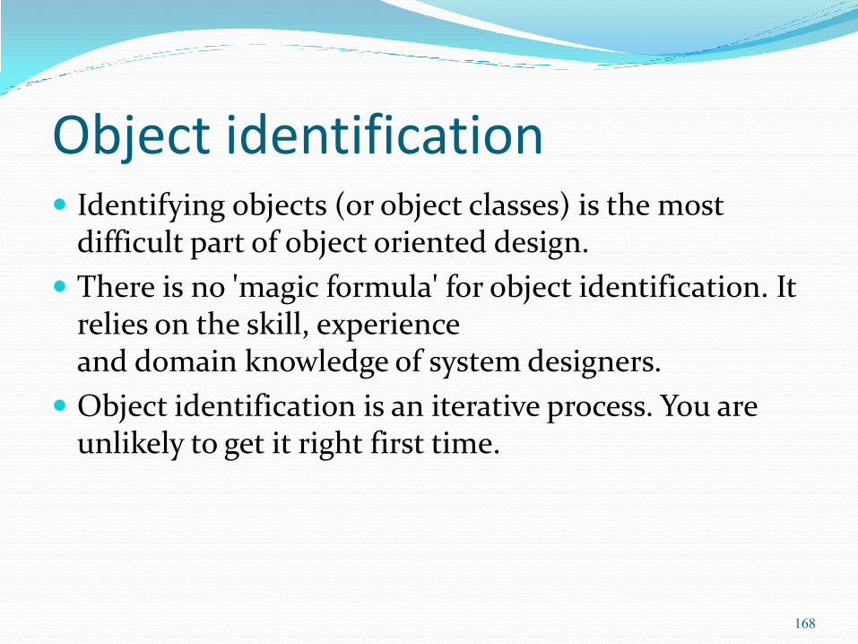
Object identification Identifying objects (or object classes) is the most
difficult part of object oriented design.
There is no 'magic formula' for object identification. It relies on the skill, experience and domain knowledge of system designers.
Object identification is an iterative process. You are unlikely to get it right first time.
168
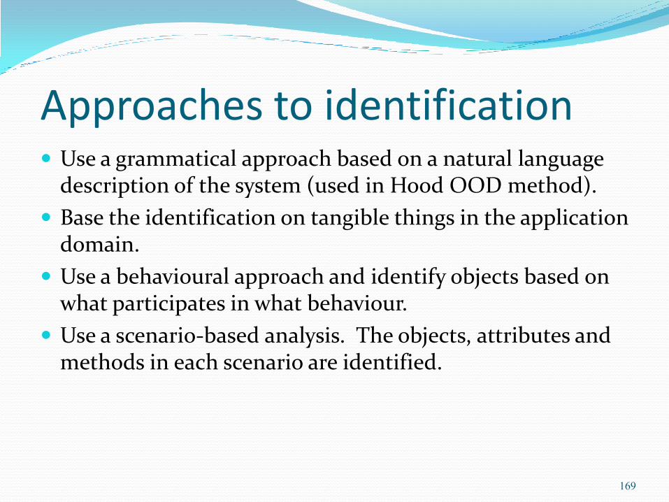
Approaches to identification Use a grammatical approach based on a natural language
description of the system (used in Hood OOD method).
Base the identification on tangible things in the application domain.
Use a behavioural approach and identify objects based on what participates in what behaviour.
Use a scenario-based analysis. The objects, attributes and methods in each scenario are identified.
169

Weather station description A weather station is a package of software controlled instruments
which collects data, performs some data processing and transmits
this data for further processing. The instruments include air and
ground thermometers, an anemometer, a wind vane, a barometer
and a rain gauge. Data is collected periodically.
When a command is issued to transmit the weather data, the
weather station processes and summarises the collected data. The
summarised data is transmitted to the mapping computer when a
request is received.
170

Weather station object classes Ground thermometer, Anemometer, Barometer
Application domain objects that are ‘hardware’ objects related to the instruments in the system.
Weather station The basic interface of the weather station to its environment. It
therefore reflects the interactions identified in the use-case model.
Weather data Encapsulates the summarised data from the instruments.
171
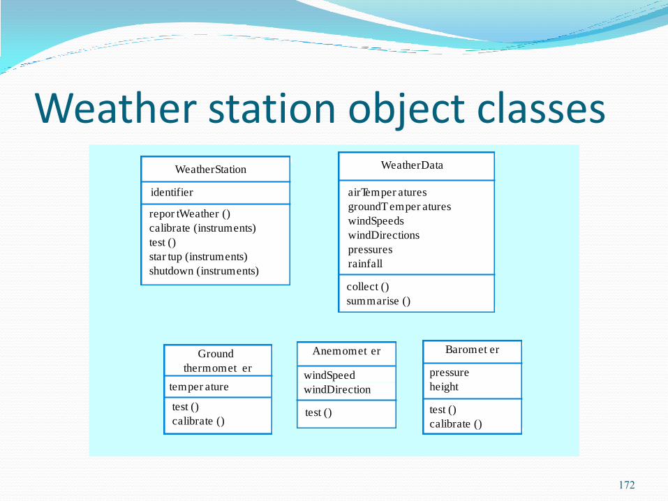
Weather station object classes
identifier
repor tWeather ()
calibrate (instruments)
test ()
star tup (instruments)
shutdown (instruments)
WeatherStation
test ()
calibrate ()
Ground
thermomet er
temper ature
Anemomet er
windSpeed
windDirection
test ()
Baromet er
pressure
height
test ()
calibrate ()
WeatherData
airTemper atures
groundT emper atures
windSpeeds
windDirections
pressures
rainfall
collect ()
summarise ()
172

Further objects and object refinement
Use domain knowledge to identify more objects and operations Weather stations should have a unique identifier;
Weather stations are remotely situated so instrument failures have to be reported automatically. Therefore attributes and operations for self-checking are required.
Active or passive objects In this case, objects are passive and collect data on request rather
than autonomously. This introduces flexibility at the expense of controller processing time.
173
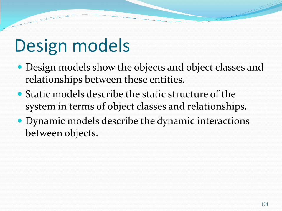
Design models Design models show the objects and object classes and
relationships between these entities.
Static models describe the static structure of the system in terms of object classes and relationships.
Dynamic models describe the dynamic interactions between objects.
174

Examples of design models Sub-system models that show logical groupings of objects
into coherent subsystems.
Sequence models that show the sequence of object interactions.
State machine models that show how individual objects change their state in response to events.
Other models include use-case models, aggregation models, generalisation models, etc.
175
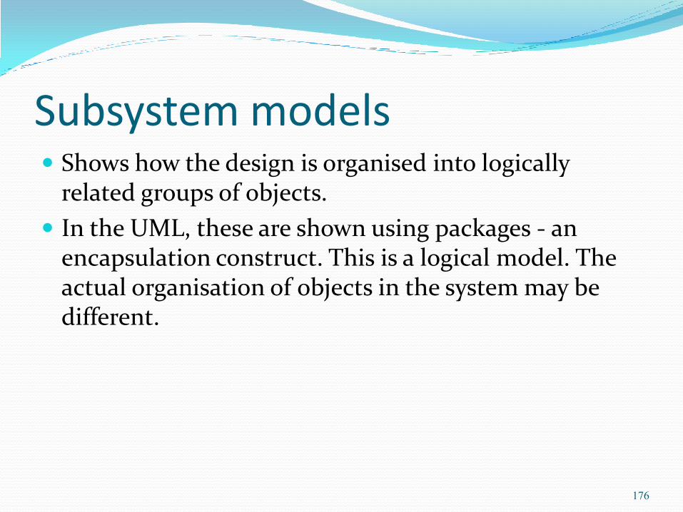
Subsystem models Shows how the design is organised into logically
related groups of objects.
In the UML, these are shown using packages - an encapsulation construct. This is a logical model. The actual organisation of objects in the system may be different.
176

Weather station subsystems « subsystem»
Inter face« subsystem»
Data collection
CommsController
WeatherStation
WeatherData
InstrumentStatus
« subsystem»Instruments
Air thermometer
Ground thermometer
RainGauge
Barometer
Anemometer
WindVane
177
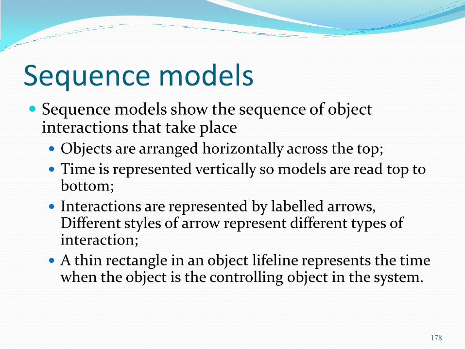
Sequence models Sequence models show the sequence of object
interactions that take place Objects are arranged horizontally across the top;
Time is represented vertically so models are read top to bottom;
Interactions are represented by labelled arrows, Different styles of arrow represent different types of interaction;
A thin rectangle in an object lifeline represents the time when the object is the controlling object in the system.
178
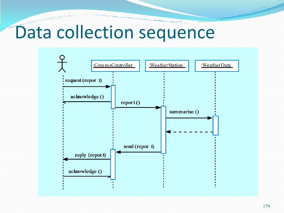
Data collection sequence
179
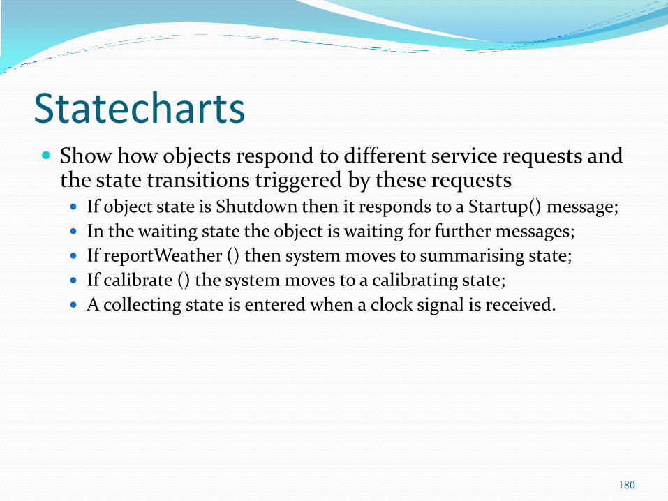
Statecharts Show how objects respond to different service requests and
the state transitions triggered by these requests If object state is Shutdown then it responds to a Startup() message;
In the waiting state the object is waiting for further messages;
If reportWeather () then system moves to summarising state;
If calibrate () the system moves to a calibrating state;
A collecting state is entered when a clock signal is received.
180

Weather station state diagram
181
Object interface specification Object interfaces have to be specified so that the objects
and other components can be designed in parallel.
Designers should avoid designing the interface representation but should hide this in the object itself.
Objects may have several interfaces which are viewpoints on the methods provided.
The UML uses class diagrams for interface specification but Java may also be used.
182
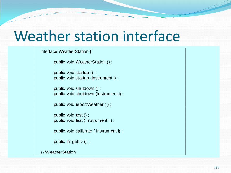
Weather station interface interface WeatherStation {
public void WeatherStation () ;
public void startup () ;
public void startup (Instrument i) ;
public void shutdown () ;
public void shutdown (Instrument i) ;
public void reportWeather ( ) ;
public void test () ;
public void test ( Instrument i ) ;
public void calibrate ( Instrument i) ;
public int getID () ;
} //WeatherStation
183
Design evolution Hiding information inside objects means that
changes made to an object do not affect other objects in an unpredictable way.
Assume pollution monitoring facilities are to be added to weather stations. These sample the air and compute the amount of different pollutants in the atmosphere.
Pollution readings are transmitted with weather data.
184
Changes required Add an object class called Air quality as part of
WeatherStation.
Add an operation reportAirQuality to WeatherStation. Modify the control software to collect pollution readings.
Add objects representing pollution monitoring instruments.
185

Pollution monitoring
NODatasmokeDatabenz eneData
collect ()summarise ()
Air quality
identifier
repor tWeather ()repor tAirQuality ()calibrate (instruments)test ()star tup (instruments)shutdown (instruments)
WeatherStation
Pollution monitoring instruments
NOmeter SmokeMeter
BenzeneMeter
186

OOD is an approach to design so that design components have their own private state and operations.
Objects should have constructor and inspection operations. They provide services to other objects.
Objects may be implemented sequentially or concurrently.
The Unified Modeling Language provides different notations for defining different object models.
Key points
187
Key points A range of different models may be produced during
an object-oriented design process. These include static and dynamic system models.
Object interfaces should be defined precisely using e.g. a programming language like Java.
Object-oriented design potentially simplifies system evolution.
188
Real-time Software Design
189
Objectives To explain the concept of a real-time system and why
these systems are usually implemented as concurrent processes
To describe a design process for real-time systems
To explain the role of a real-time operating system
To introduce generic process architectures for monitoring and control and data acquisition systems
190
Topics covered System design
Real-time operating systems
Monitoring and control systems
Data acquisition systems
191
Real-time systems Systems which monitor and control their
environment.
Inevitably associated with hardware devices
Sensors: Collect data from the system environment;
Actuators: Change (in some way) the system's environment;
Time is critical. Real-time systems MUST respond within specified times.
192

Definition
A real-time system is a software system where the correct functioning of the system depends on the results produced by the system and the time at which these results are produced.
A soft real-time system is a system whose operation is degraded if results are not produced according to the specified timing requirements.
A hard real-time system is a system whose operation is incorrect if results are not produced according to the timing specification.
193

Stimulus/Response Systems Given a stimulus, the system must produce a
response within a specified time.
Periodic stimuli. Stimuli which occur at predictable time intervals For example, a temperature sensor may be polled 10 times per
second.
Aperiodic stimuli. Stimuli which occur at unpredictable times For example, a system power failure may trigger an
interrupt which must be processed by the system.
194
Architectural considerations Because of the need to respond to timing demands made
by different stimuli/responses, the system architecture must allow for fast switching between stimulus handlers.
Timing demands of different stimuli are different so a simple sequential loop is not usually adequate.
Real-time systems are therefore usually designed as cooperating processes with a real-time executive controlling these processes.
195
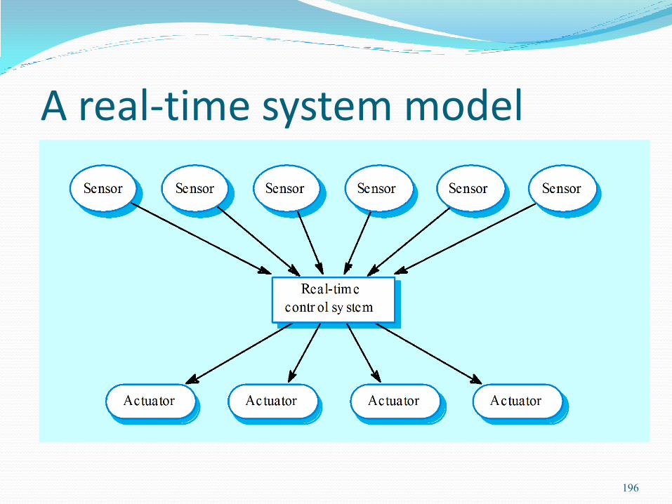
A real-time system model
196

Sensor/actuator processes
197

System elements Sensor control processes
Collect information from sensors. May buffer information collected in response to a sensor stimulus.
Data processor
Carries out processing of collected information and computes the system response.
Actuator control processes
Generates control signals for the actuators.
198
Monitoring and control systems Important class of real-time systems.
Continuously check sensors and take actions depending on sensor values.
Monitoring systems examine sensors and report their results.
Control systems take sensor values and control hardware actuators.
199

Generic architecture
200

Assignment Explain Monitoring & Control systems
201
Research Monitoring Greenhouse using Wireless Sensor
Network - Accent
202