unit-5 input-output organizationcpu/ iop communication send instruction to test iop.path if status...
TRANSCRIPT

UNIT-5 INPUT-OUTPUT
ORGANIZATION
1
2
5.1Input-Output Interface
5.2 Asynchronous Data Transfer
5.3 Strobe Control
5.4 Handshaking
5.5 Asynchronous Serial Transfer
5.6 Modes of Data Transfer
5.7 Input-Output Processor (IOP)
TOPICS TO BE COVERED…

5.1INPUT-OUTPUT INTERFACE
Provides a method for transferring information
between internal storage (such as memory and
CPU registers) and external I/O devices
o Resolves the differences between the
computer and peripheral devices
3

I/O BUS TO I/O DEVICES
Each peripheral has an interface module associatedwith itOperation of Interface unit
Processor
Interface
Keyboardand
displayterminal
Magnetictape
Printer
Interface Interface Interface
Data
Address
Control
Magneticdisk
I/O bus
4

Decodes the device address (device code)
Decodes the commands (operation)
Provides signals for the peripheral controller
Synchronizes the data flow and supervises
the transfer rate between peripheral and CPU
or Memory
5
CONNECTION OF I/O BUS There are four types of commands that an
interface may receive :
1. Control Command
It activate the peripheral devices and inform
what to do..
2. Status Command
it used to test various condition in peripheral
and an interface(Check the status of
peripheral device before transmission.)
3.Data output Command
it transferring the data from bus into its own
register 6
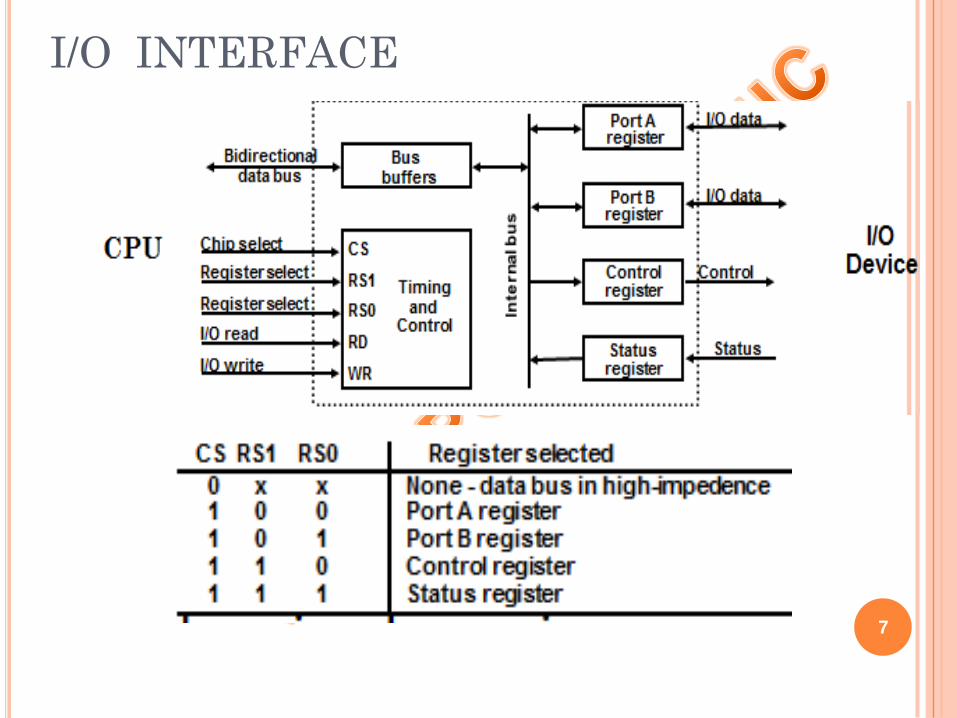
I/O INTERFACE
7
Here each port can be assigned a meaning depending
on the mode of operation of the I/O device.
Port A = data
Port B = Command
8

5.2 ASYNCHRONOUS DATA
TRANSFER
Synchronous - All devices derive the timing
information from common clock line
Asynchronous - No common clock
Synchronous and Asynchronous Operations
Asynchronous Data Transfer
Two Asynchronous Data Transfer Methods
9

10
Strobe pulse
A strobe pulse is supplied by one unit to indicate
the other unit when the transfer has to occur
Handshaking
A control signal is accompanied with each data
being transmitted to indicate the presence of data
The receiving unit responds with another control
signal to acknowledge receipt of the data

5.3 STROBE CONTROL
Sourceunit
Destinationunit
Data bus
Strobe
Data
Strobe
Valid data
Block Diagram
Timing Diagram
Source-Initiated Strobe
for Data Transfer
Source
unit
Destination
unit
Data bus
Strobe
Data
Strobe
Valid data
Block Diagram
Destination-Initiated Strobe
for Data Transfer
Timing Diagram
11
5.4 HANDSHAKING
Strobe Methods
Source-Initiated
The source unit that initiates the transfer hasno way of knowing whether the destination unithas actually received data
Destination-Initiated
The destination unit that initiates the transfer no way of knowing whether the source hasactually placed the data on the bus
12

SOURCE-INITIATED TRANSFER USING
HANDSHAKEBlock Diagram
Timing Diagram
Accept data from bus.Enable data accepted
Disable data accepted.Ready to accept data(initial state).
Sequence of EventsPlace data on bus.Enable data valid.
Source unit Destination unit
Disable data valid.Invalidate data on bus.
Sourceunit
Destinationunit
Data bus
Data accepted
Data bus
Data valid
Valid data
Data valid
Data accepted
13

DESTINATION-INITIATED TRANSFER
USING HANDSHAKE
*
Block Diagram
Timing Diagram
Sourceunit
Destinationunit
Data bus
Ready for data
Data valid
Sequence of Events
Place data on bus.Enable data valid.
Source unit Destination unit
Ready to accept data.Enable ready for data.
Disable data valid.Invalidate data on bus(initial state).
Accept data from bus.Disable ready for data.
Ready for data
Data valid
Data busValid data
14

5.5 ASYNCHRONOUS SERIAL
TRANSFER
1. Asynchronous serial transfer2. Synchronous serial transfer3. Asynchronous parallel transfer4. Synchronous parallel transfer
Four Different Types of Transfer
15
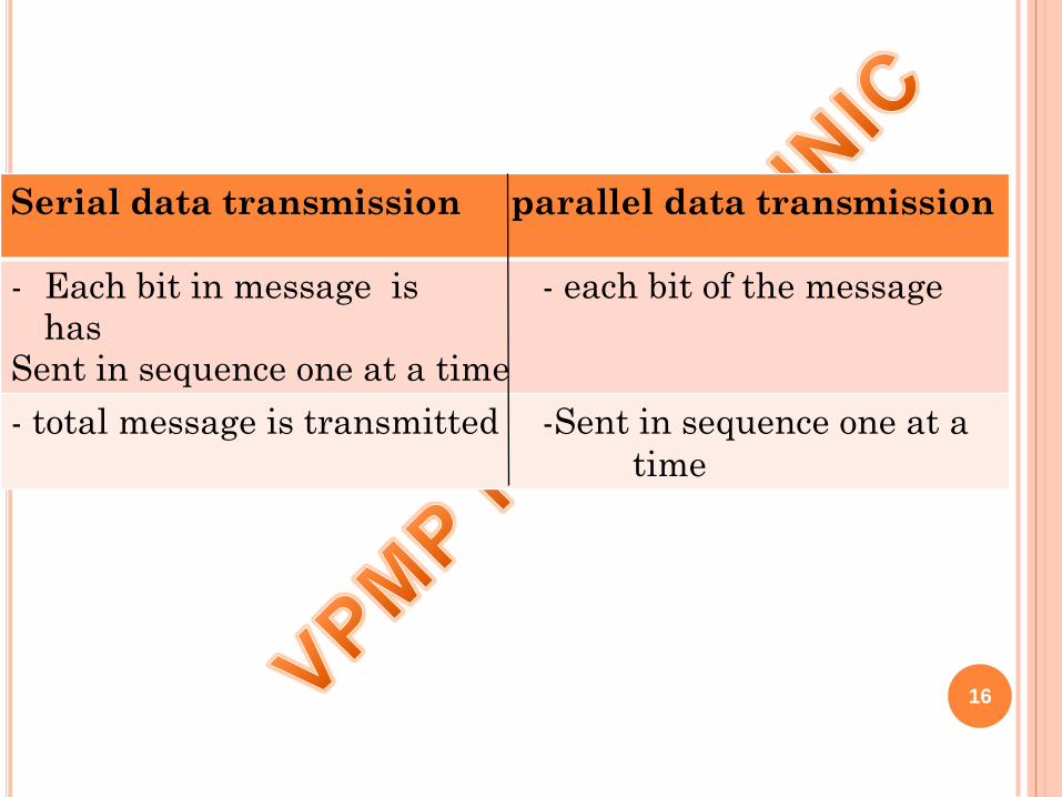
Serial data transmission parallel data transmission
- Each bit in message is - each bit of the message has
Sent in sequence one at a time
- total message is transmitted -Sent in sequence one at a
time
16

SYNCHRONOUS SERIAL TRANSFER
In synchronous transmission , the two units
share a common bits are transmitted continually
In synchronous transmission , signals are
transmitted periodically between two units
Data are continually sending one by one at a time
17

- When data are not being sent, the line is kept in the 1-state (idle state)
- The initiation of a character transmission is detected
by a Start Bit , which is always a 0
ASYNCRONOUS SERIAL TRANSMISSION
Transmission of multiple data at a same time
If data are available then send otherwise not & line remain idle
18
5.6 MODES OF DATA TRANSFER
Data transfer between memory & I/O devices
handled by various modes
1. Programed I/O
2. Interrupt-initiated I/O
3. Direct memory access(DMA)
19

5.7 INPUT OUTPUT PROCESSOR
A transfer from an I/O device to memory requires
the execution of several instruction by the CPU ,
including an input instruction to transfer the
data from the device to the CPU and a store
instruction to transfer the data from the CPU to
memory.
20
EXAMPLE OF DATA TRANSFER IN
PROGRAMMED I/O(BETWEEN I/O DEVICE
TO CPU)
21
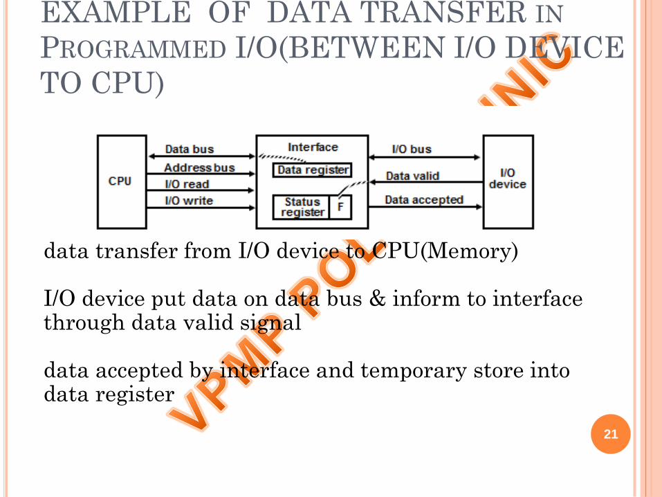
data transfer from I/O device to CPU(Memory)
I/O device put data on data bus & inform to interface through data valid signal
data accepted by interface and temporary store into data register
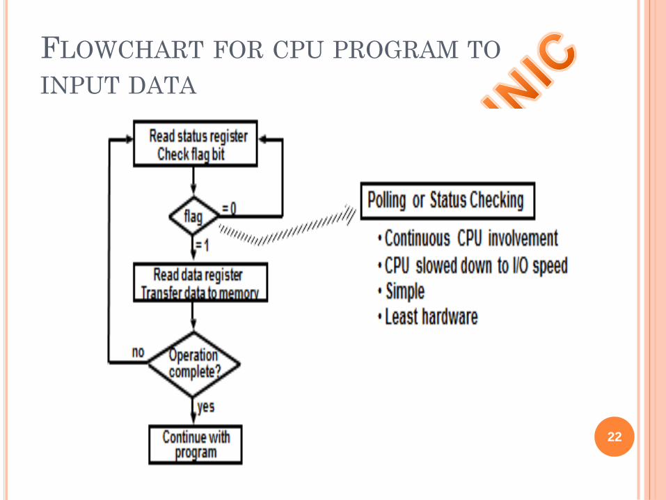
FLOWCHART FOR CPU PROGRAM TO
INPUT DATA
22

INTERRUPT-INITIATED I/O
special command informed to interface about
received input signal
when data are available in I/O device
when interface determine the device is ready for
data transfer then it generate interrupt request to
computer
computer instantly reply to interface , means it stop
any kind of working by CPU & accept the interrupt
request & after that complete pending work.
23

METHODS OF INTERRUPT
INITIATED :
1.VECTORED INTERRUPT :
source sending branch information to the
computer is called vectored interrupt
2. NON-VECTIRED INTERRUPT :
the branch address is assigned to fixed
location in memory is called non-vectored
interrupt
24
DIRECT MEMORY ACCESS(DMA)
In DMA, the interface transfer data into & out of
the memory unit through the memory bus.
DMA Controller : it is an interface that provide
I/O transfer of data directly to & from the
memory and the I/O device.
25

BLOCK DIAGRAM OF DMA
CONTROLLER
26
INPUT/OUTPUT PROCESSOR (IOP) Processor with direct memory access capability
that communicates with I/O devices
Channel accesses memory by cycle stealing
Channel can execute a Channel Program
Stored in the main memory
Consists of Channel Command Word(CCW)
Each CCW specifies the parameters needed
by the channel to control the I/O devices and
perform data transfer operations
CPU initiates the channel by executing an
27
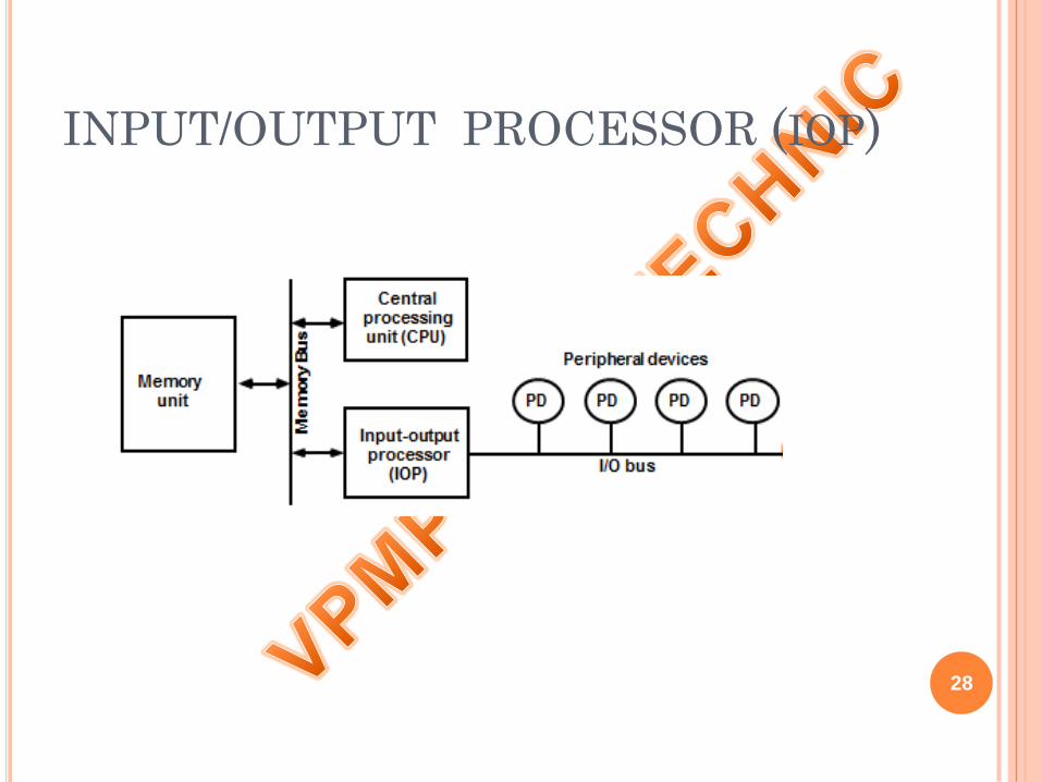
INPUT/OUTPUT PROCESSOR (IOP)
28

CPU/ IOP COMMUNICATION
Send instructionto test IOP.path
If status OK, then sendstart I/O instruction
to IOP.
CPU continues withanother program
Transfer status wordto memory
Access memoryfor IOP program
Conduct I/O transfersusing DMA;
Prepare status report.
I/O transfer completed;Interrupt CPU
Request IOP status
Transfer status wordto memory locationCheck status word
for correct transfer.
Continue
CPU operations IOP operations
29