unit 7 (oscillations) 8e - pbworks
TRANSCRIPT

Honors Physics
Student Worksheets
Unit 7 - Simple Harmonic Motion

Name:
Super Teacher Worksheets - www.superteacherworksheets.com
Electrical Charges
If an object has more positive charges ( )than negative charges ( ), its electricalcharge is positive ( ).
If an object has more negative charges ( )than positive charges ( ), its electricalcharge is negative ( ).
If an object has the same number of positive( ) and negative ( ) charges, it has noelectrical charge or is neutral.
Example:
Electrical charge: positive charge
Count the positive and negative charges in each picture. Write positive charge,negative charge, or no charge on each line.
1.
electrical charge:
2.
electrical charge:
3.
electrical charge:
4.
electrical charge:
5.
electrical charge:
6.
electrical charge:
9

Name: ____________________________________
Static Electricity
Rubbing a balloon with wool cloth will create static electricity charges.
In Picture 1, does the balloon have a positive charge, negative charge, or no charge? ______________
In Picture 1, does the cloth have a positive charge, negative charge, or no charge? __________________
In Picture 2, does the balloon have a positive charge, negative charge, or no charge? ______________
In Picture 2, does the cloth have a positive charge, negative charge, or no charge? ______________
If you place small pieces of tissue paper near the balloon in Picture 2, they would probably stick to the
balloon. Explain why.
___________________________________________________________________________________________________
___________________________________________________________________________________________________
___________________________________________________________________________________________________
___________________________________________________________________________________________________
Super Teacher Worksheets - www.superteacherworksheets.com
10

Aluminum Can Polarization
Purpose: To explain the cause of the interaction between a charged object (either positively- or negatively-charged) and a neutral aluminum pop can.
Getting Ready: Navigate to the Aluminum Can Polarization Interactive at The Physics Classroom:
http://www.physicsclassroom.com/Physics-Interactives/Static-Electricity/Aluminum-Can-Polarization
Path: Physics Interactives ==> Static Electricity ==> Aluminum Can Polarization
Explore-Interact-Learn: Investigate the interaction between a glass rod and a rubber rod and the aluminum can. Play with the simulation, moving the rods about the screen and observing the behavior of charges within the pop can. Then complete the models below by shading in the areas where electrons tend to congregate most densely.
Conclusion: Describe what must happen inside of an aluminum can in order for it to be attracted to a positively-charged and to a negatively-charged object.
Diagram A Diagram B Diagram C
Diagram D Diagram E
© Pearson Education, Inc., publishing as Pearson Prentice Hall. All rights reserved.
Name ____________________________ Date____________________ Class ____________
Electricity Section Summary
Electric Charge and Static ElectricityGuide for Reading How do electric charges interact?
What is an electric field?
How does static electricity build up and transfer?
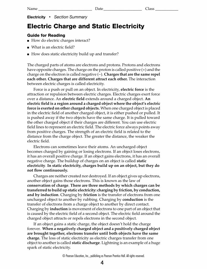
The charged parts of atoms are electrons and protons. Protons and electrons have opposite charges. The charge on the proton is called positive (+) and the charge on the electron is called negative (−). Charges that are the same repel each other. Charges that are different attract each other. The interaction between electric charges is called electricity.
Force is a push or pull on an object. In electricity, electric force is the attraction or repulsion between electric charges. Electric charges exert force over a distance. An electric field extends around a charged object. An electric field is a region around a charged object where the object’s electric force is exerted on other charged objects. When one charged object is placed in the electric field of another charged object, it is either pushed or pulled. It is pushed away if the two objects have the same charge. It is pulled toward the other charged object if their charges are different. You can use electric field lines to represent an electric field. The electric force always points away from positive charges. The strength of an electric field is related to the distance from the charge object. The greater the distance, the weaker the electric field.
Electrons can sometimes leave their atoms. An uncharged object becomes charged by gaining or losing electrons. If an object loses electrons, it has an overall positive charge. If an object gains electrons, it has an overall negative charge. The buildup of charges on an object is called static electricity. In static electricity, charges build up on an object, but they do not flow continuously.
Charges are neither created nor destroyed. If an object gives up electrons, another object gains those electrons. This is known as the law of conservation of charge. There are three methods by which charges can be transferred to build up static electricity: charging by friction, by conduction, and by induction. Charging by friction is the transfer of electrons from one uncharged object to another by rubbing. Charging by conduction is the transfer of electrons from a charge object to another by direct contact. Charging by induction is movement of electrons to one part of an object that is caused by the electric field of a second object. The electric field around the charged object attracts or repels electrons in the second object.
If an object gains a static charge, the object doesn’t hold the charge forever. When a negatively charged object and a positively charged object are brought together, electrons transfer until both objects have the same charge. The loss of static electricity as electric charges transfer from one object to another is called static discharge. Lightning is an example of a huge spark of static electricity.

© Pearson Education, Inc., publishing as Pearson Prentice Hall. All rights reserved.
Name ____________________________ Date____________________ Class ____________E
lec
tricity
Electricity Guided Reading and Study
Electric Charge and Static ElectricityThis section describes how electric charges interact and explains what an electric field is. It also explains what static electricity.
Use Target Reading SkillsBefore you read, preview Figure 4 in your text. Then write two questions that you have about the diagram in the graphics organizer below. As you read, answer your questions.
Electric Charge1. The charge on a proton is called ________________________.
2. The charge on an electron is called ________________________.
3. Circle the letter of each statement that is true about interactions between charges.a. Charges that are the same repel each other.b. Charged objects never attract each other.c. Charges that are different attract each other.d. Charged objects always repel each other.
4. Why do protons repel protons but attract electrons?_________________________________________________________________________
_________________________________________________________________________
5. The interaction between electric charges is called ________________________.
Q. What are the three ways static electricity can be transferred?
A.
Q.
A.
Transferring Static Electricity

© Pearson Education, Inc., publishing as Pearson Prentice Hall. All rights reserved.
Name ____________________________ Date____________________ Class ____________
Electricity Guided Reading and Study
Electric Charge and Static Electricity (continued)
Electric Force6. What is electric force?
_________________________________________________________________________
_________________________________________________________________________
7. What is a region around a charged object where the object’s eletric force is exterted on other charged objects?
_________________________________________________________________________
8. Electric field lines are drawn with arrows to show the ________________________ of the electric force.
9. Is the following sentence true or false? The greater the distance, the stronger the electric field. ________________________
10. When there are two or more charges, the electric fields of each individual charge ________________________ by repellng or attracting.
Static Electricity11. Circle the letter of the sentence that explains why there is no overall
electric charge in a neutral object.a. In the object’s atoms, each positive charge is balanced by a negative
charge.b. The object’s atoms contain no charged particles.c. The positive charges are attracted to other positive charges.d. In the object’s atoms, negative charges outnumber positive charges.
12. How can an object become charged? _________________________________________________________________________
_________________________________________________________________________
_________________________________________________________________________
13. The buildup of charges on an object is called ________________________.
14. If an object gains electrons, what will be its overall charge? ________________________
© Pearson Education, Inc., publishing as Pearson Prentice Hall. All rights reserved.
Name ____________________________ Date____________________ Class ____________E
lec
tricity
Electricity Guided Reading and Study
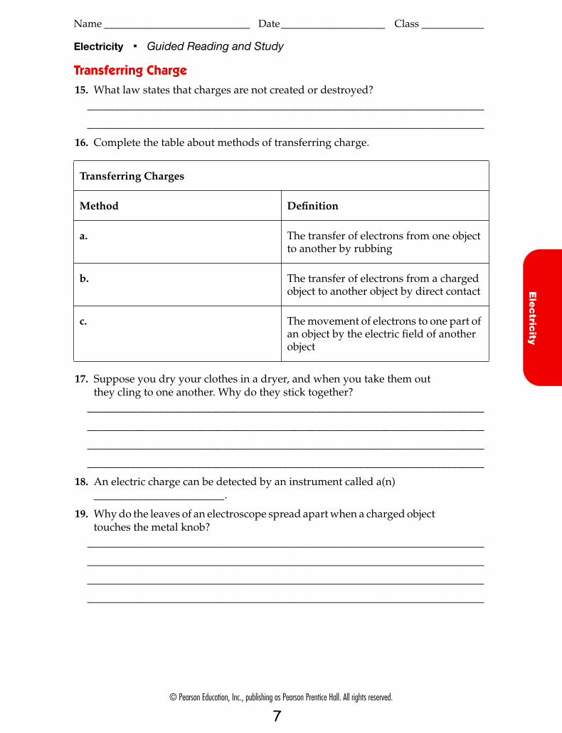
Transferring Charge15. What law states that charges are not created or destroyed?
_________________________________________________________________________
_________________________________________________________________________
16. Complete the table about methods of transferring charge.
17. Suppose you dry your clothes in a dryer, and when you take them out they cling to one another. Why do they stick together?
_________________________________________________________________________
_________________________________________________________________________
_________________________________________________________________________
_________________________________________________________________________
18. An electric charge can be detected by an instrument called a(n) ________________________.
19. Why do the leaves of an electroscope spread apart when a charged object touches the metal knob?
_________________________________________________________________________
_________________________________________________________________________
_________________________________________________________________________
_________________________________________________________________________
Transferring Charges
Method Definition
a. The transfer of electrons from one object to another by rubbing
b. The transfer of electrons from a charged object to another object by direct contact
c. The movement of electrons to one part of an object by the electric field of another object

© Pearson Education, Inc., publishing as Pearson Prentice Hall. All rights reserved.
Name ____________________________ Date____________________ Class ____________
Electricity Guided Reading and Study
Electric Charge and Static Electricity (continued)
Static Discharge20. What happens when a negatively charged object and a positively
charged object are brought together?_________________________________________________________________________
_________________________________________________________________________
21. The loss of static electricity as electric charges transfer from one object to another is called ________________________.
22. Is the following sentence true or false? Lightning is an example of static discharge. ________________________
© Pearson Education, Inc., publishing as Pearson Prentice Hall. All rights reserved.
Name ____________________________ Date____________________ Class ____________E
lec
tricity
Electricity Review and Reinforce
Electric Charge and Static Electricity
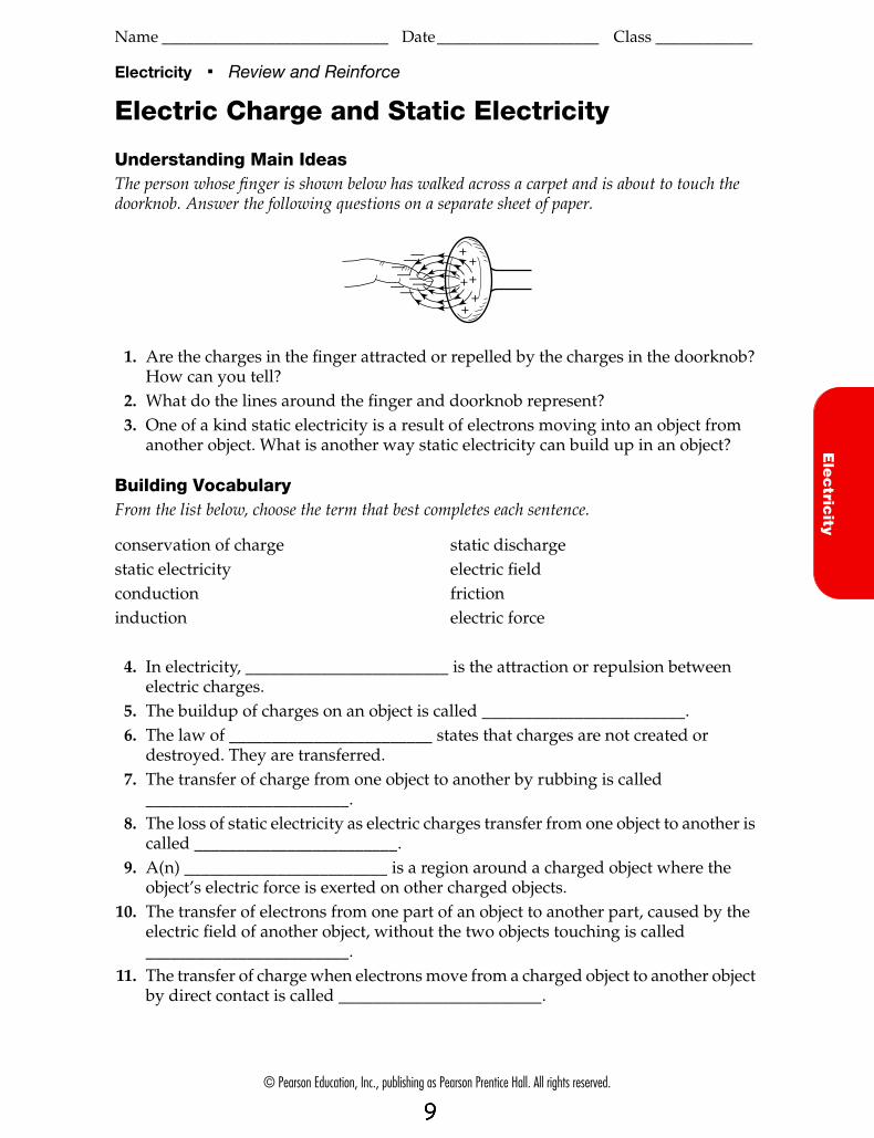
Understanding Main IdeasThe person whose finger is shown below has walked across a carpet and is about to touch the doorknob. Answer the following questions on a separate sheet of paper.
1. Are the charges in the finger attracted or repelled by the charges in the doorknob? How can you tell?
2. What do the lines around the finger and doorknob represent?3. One of a kind static electricity is a result of electrons moving into an object from
another object. What is another way static electricity can build up in an object?
Building VocabularyFrom the list below, choose the term that best completes each sentence.
++
++
+—
——
————— +
conservation of chargestatic electricityconductioninduction
static dischargeelectric fieldfrictionelectric force
4. In electricity, ________________________ is the attraction or repulsion between electric charges.
5. The buildup of charges on an object is called ________________________.6. The law of ________________________ states that charges are not created or
destroyed. They are transferred.7. The transfer of charge from one object to another by rubbing is called
________________________.8. The loss of static electricity as electric charges transfer from one object to another is
called ________________________.9. A(n) ________________________ is a region around a charged object where the
object’s electric force is exerted on other charged objects.10. The transfer of electrons from one part of an object to another part, caused by the
electric field of another object, without the two objects touching is called ________________________.
11. The transfer of charge when electrons move from a charged object to another object by direct contact is called ________________________.

Name: Electrostatics Worksheet #1 Conceptual Physics 1. Describe the charge distribution for an object that is… electrically positive electrically negative electrically neutral 2. Draw the charge distribution on the objects below. Include at least 8 charges. Electrically positive electrically negative electrically neutral 3. What will occur if you bring a negatively charged rubber rod near each of the charged spheres? Indicate the interaction between the spheres and the rod (attract or repel). Electrically positive electrically negative electrically neutral
- - - - - - + - - - - - - - - - - - - - + - 4. What will occur if you bring a positively charged glass rod near each of the charged spheres? Indicate the interaction between the spheres and the rod (attract or repel). Electrically positive electrically negative electrically neutral
+ + + + + + + + + + + - + + + + + - +

Electrostatics Worksheet #1 (continued) 5. Describe polarization of charge on a neutral object. Draw the charge distribution on the spheres as a negatively charged rubber rod or a positively charged glass rod are brought near the neutral sphere. Draw at least 8 charges on the spheres. electrically neutral sphere electrically neutral sphere
- - - - - - + + + + + + The charges on a polarized object… 6. Describe two ways of charging objects by touching them together. What is the difference between the two methods? 7. Draw the movement of charges as a neutral conducting sphere is charge by conduction with a negatively charged rubber rod. Include at least 8 charges on the sphere. Before During After
- - - - - - - - - - - - 8. Describe induction (charging objects that involves no contact between the charged object and object being charged). 9. What is a conductor? Why is metal a good conductor? 10. What is an insulator? What kinds of substances are good insulators?

Name Conceptual Physics Electrostatics Worksheet #2 1. How do protons and electrons differ in their electrical charge? 2. If an atom (or object) is neutral, how many electrons are there compared to the number of
protons? 3. Explain in terms of comparative numbers of protons and electrons why an object has a
negative charge? A positive charge? Draw a diagram of a positively charged object and a negatively charged object.
4. How do like charges behave toward each other? 5. How do unlike charges behave toward each other? 6. How do neutral objects behave toward charged objects? What is happening? 7. What does it mean to say that an object is electrically polarized? Draw a diagram of a
electrically polarized conducting sphere near a positively charged glass rod. 8. What does it mean to say that charge is conserved?

Electrostatics Worksheet #2 (continued) 9. What is an elementary charge? What are the two kinds of elementary charges? 10. What unit is used to measure electrical charge? 11. How much electrical charge does an electron carry? (in Coulombs) 12. How much electrical charge does a proton carry? (in Coulombs) 13. How many elementary charges are in one Coulomb of charge? 14. What is the charge in Coulombs on an object that has 356 more protons than electrons?
15. An object has an electrical charge of -1.2 x 10⁻¹⁶ C. How many excess elementary charges does it have? What kind are they?
16. An object has 8.25 x 10¹³ protons and 5.0 x 10¹³ electrons. What is the charge on the object? (First figure out how many excess charges it has. )
17. Two charged conducting objects are brought together and then separated. How much charge
is left on each of the objects? A. +5 μC - 2 μC B. – 8 μC - 1 μC C. +10 μC +4 μC
From The Physics Classroom's Physics Interactives http://www.physicsclassroom.com
©The Physics Classroom, All Rights Reserved This document should NOT appear on other websites.
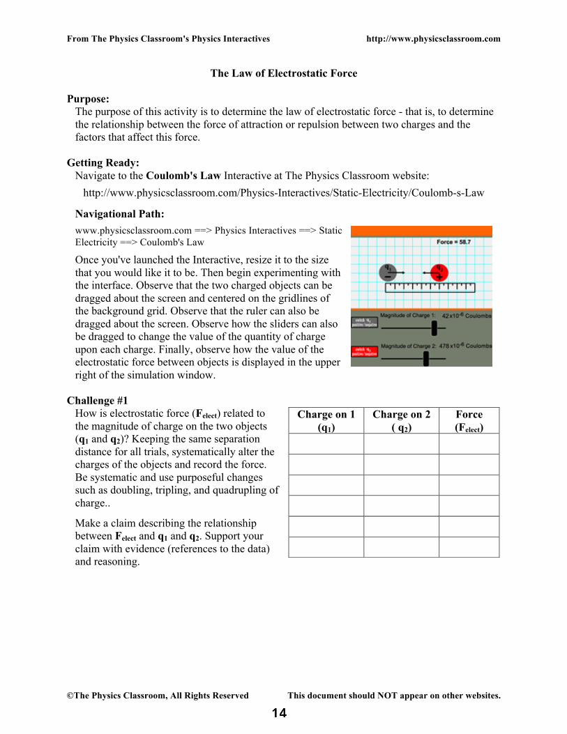
The Law of Electrostatic Force Purpose:
The purpose of this activity is to determine the law of electrostatic force - that is, to determine the relationship between the force of attraction or repulsion between two charges and the factors that affect this force.
Getting Ready:
Navigate to the Coulomb's Law Interactive at The Physics Classroom website:
http://www.physicsclassroom.com/Physics-Interactives/Static-Electricity/Coulomb-s-Law
Navigational Path:
www.physicsclassroom.com ==> Physics Interactives ==> Static Electricity ==> Coulomb's Law
Once you've launched the Interactive, resize it to the size that you would like it to be. Then begin experimenting with the interface. Observe that the two charged objects can be dragged about the screen and centered on the gridlines of the background grid. Observe that the ruler can also be dragged about the screen. Observe how the sliders can also be dragged to change the value of the quantity of charge upon each charge. Finally, observe how the value of the electrostatic force between objects is displayed in the upper right of the simulation window.
Challenge #1 How is electrostatic force (Felect) related to the magnitude of charge on the two objects (q1 and q2)? Keeping the same separation distance for all trials, systematically alter the charges of the objects and record the force. Be systematic and use purposeful changes such as doubling, tripling, and quadrupling of charge..
Make a claim describing the relationship between Felect and q1 and q2. Support your claim with evidence (references to the data) and reasoning.
Charge on 1 (q1)
Charge on 2 ( q2)
Force (Felect)

From The Physics Classroom's Physics Interactives http://www.physicsclassroom.com
©The Physics Classroom, All Rights Reserved This document should NOT appear on other websites.
Challenge #2 How is the electrostatic force (Felect) related to the separation distance (d) the two charges? Keeping the magnitude of charge on both objects constant, conduct a systematic study to collect data relating separation distance to force. The separation distance is defined as the distance between the centers of the two objects; the best strategy involves centering the objects on a gridline and using distances that are a whole number of squares.
Make a claim describing the relationship between Felect and d. Support your claim with evidence (references to the data) and reasoning.
Conclusion:
Suggest an equation relating Felect, q1, q2 and d of the form Felect = k•... where k is a proportionality constant (no need to determine its value). Place the three variables q1, q2 and d on the right side of the equation in a numerator or a denominator; use a power if needed. Your equation should be consistent with your claims made in Challenge #1 and Challenge #2.
Separation Distance (d)
Force (Felect)
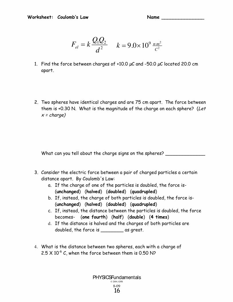
Worksheet: Coulomb’s Law Name _______________
PHYSICSFundamentals © 2004, GPB
8-09
1 22el
QQF kd
2
299.0 10 n m
Ck u
1. Find the force between charges of +10.0 µC and -50.0 µC located 20.0 cm
apart.
2. Two spheres have identical charges and are 75 cm apart. The force between
them is +0.30 N. What is the magnitude of the charge on each sphere? (Let x = charge)
What can you tell about the charge signs on the spheres? ______________ 3. Consider the electric force between a pair of charged particles a certain
distance apart. By Coulomb's Law: a. If the charge of one of the particles is doubled, the force is-
(unchanged) (halved) (doubled) (quadrupled) b. If, instead, the charge of both particles is doubled, the force is-
(unchanged) (halved) (doubled) (quadrupled) c. If, instead, the distance between the particles is doubled, the force
becomes- (one fourth) (half) (double) (4 times) d. If the distance is halved and the charges of both particles are
doubled, the force is ________ as great.
4. What is the distance between two spheres, each with a charge of
2.5 X 10⁻⁶ C, when the force between them is 0.50 N?

Name: Date:
15.2Coulomb’s Law
In this skill sheet, you will work with Coulomb’s law. There are many similarities and some differences between the equation of universal gravitation and the equation for Coulomb’s law. They are both inverse square law relationships, and they both have similar arrangements of variables.
When two charges q1 and q2 are separated by a distance r, there exists a force between them that is given by:
where F equals the force in newtons and K is a constant equal to 9 109 N-m2/C2. The units of q1 and q2 are the coulombs (C). Distance is given in meters. Here are some important points about the relationships of the variables in Coulomb’s law.
• Force is inversely proportional to the square of the distance between the charges. Therefore, if the distance increases by a factor of 2, the force decreases by a factor of 4.
• Force is proportional to the strength of each charge.
• When the two charges have the same sign (positive or negative), the force between them is repulsive because like charges repel.
• When the charges have opposite signs, the force between them is attractive because unlike charges attract.
1. What happens to the force between two charges if the distance between them is tripled?
2. What happens to the force between two charges if the distance between them is quadrupled?
3. What happens to the force between two charges if the distance between them is cut in half?
4. What happens to the force between two charges if the magnitude of one charge is doubled?
5. What happens to the force between two charges is the magnitude of both charges is doubled?
6. What happens to the force between two charges if the magnitude of both charges is doubled and the distance between them is doubled?
7. What happens to the force between two charges if the magnitude of both charges is doubled and the distance between them is cut in half?

Page 2 of 2
15.2
The example below shows how to use Coulomb’s law to calculate the strength of the force between two charges.
A 0.001 coulomb charge and a 0.002 coulomb charge are 2 meters apart. Calculate the force between them.
1. Two particles, each with a charge of 1 C, are separated by a distance of 1 meter. What is the force between the particles?
2. What is the force between a 3 C charge and a 2 C charge separated by a distance of 5 meters?
3. Calculate the force between a 0.006 C charge and a 0.001 C charge 4 meters apart.
4. Calculate the force between a 0.05 C charge and a 0.03 C charge 2 meters apart.
5. Two particles are each given a charge of 5 10-5 C. What is the force between the charged particles if the distance between them is 2 meters?
6. The force between a pair of charges is 100 newtons. The distance between the charges is 0.01 meter. If one of the charges is 2 10-10 C, what is the strength of the other charge?
7. Two equal charges separated by a distance of 1 meter experience a repulsive force of 1,000 newtons. What is the strength in coulombs of each charge?
8. The force between a pair of 0.001 C charges is 200 N. What is the distance between them?
9. The force between two charges is 1000 N. One has a charge of 2 10-5 C, and the other has a charge of 5 10-6 C. What is the distance between them?
10. The force between two charges is 2 newtons. The distance between the charges is 2 10-4 m. If one of the charges is 3 10-6 C, what is the strength of the other charge?
Given
The charges have magnitudes of 0.003 C and 0.005 C.
The charges are 2 meters apart.
Solution
The force is 4500 newtons.
Looking for
The force between the charges.
Relationships
IV
R---=9 2 2
2
(0.001 C)(0.002 C)(9 10 N m /C )
(2 m)
4500 N
F
F
IV
R---= 1 2
2
q qF k
r

From The Physics Classroom’s Physics Interactive http://www.physicsclassroom.com
©The Physics Classroom, All Rights Reserved This document should NOT appear on other websites.
Electric Pressure, Current and Resistance
Purpose: The purpose of this activity is to determine the mathematical relationship between battery voltage (∆V), current (I), and resistance (R) for a simply circuit.
Getting Ready:
Navigate to the DC Circuit Builder Interactive at The Physics Classroom:
www.physicsclassroom.com => Physics Interactives => Electric Circuits => DC Circuit Builder
or http://www.physicsclassroom.com/Physics-Interactives/Electric-Circuits/Circuit-Builder. Resize the Interactive using the small handles in the bottom right corner or go full-screen by tapping the icon in the upper left corner. Observe the tools in the Toolbox region below the red Workspace area. Experiment with these tools to create a circuit. Simply select a circuit component and tap on the workspace to add it to the circuit; add wires, resistors, bulbs and ammeters as desired. Tap on a component in the workspace to remove it.
Build, Measure, Analyze 1. Clear your Workspace by clicking on all components; only the battery should remain.
Using the tools in the Toolbox area, create a simple circuit consisting of a battery, a bulb, an ammeter (for measuring current in amps), and wires.
2. Select the Modify icon (shown at right); observe that the magnifying glass appears over the battery. This indicates that you can change the voltage of the battery. Use the arrows to lower the battery voltage to 6.0 Volts.
3. The ammeter reads the current (I) in amps. Record the ammeter reading in Table 1. 4. Repeat steps 2 and 3 until Table 1 is complete. Use the Modify icon to increase the
voltage of the battery (∆V) for each of these trials. 5. Tap the Modify icon and then tap on the light bulb. The resistance (R) of the light bulb is
displayed. Record this resistance value above Table 1. Then double the value of the light bulb's resistance and repeat the experiment for Table 2. Complete Table 3 with a resistance value that is three times as large.
Table 1
R = __________ Ω Table 2
R = __________ Ω Table 3
R = __________ Ω ∆V (volts) I (amps) ∆V (volts) I (amps) ∆V (volts) I (amps)
1 6.0 7 6.0 13 6.0
2 8.0 8 8.0 14 8.0
3 10.0 9 10.0 15 10.0
4 12.0 10 12.0 16 12.0
5 18.0 11 18.0 17 18.0
6 24.0 12 24.0 18 24.0
Modify

From The Physics Classroom’s Physics Interactive http://www.physicsclassroom.com
©The Physics Classroom, All Rights Reserved This document should NOT appear on other websites.
For the following questions, make a claim (answer) and support it with evidence (reference to specific trials) and reasoning that explain why those specific trials support the claim.
7. Observe your data tables. What effect does a doubling of the battery voltage (∆V) have upon the current (I)? (Be sure to use claim-evidence-reasoning format.)
8. What effect does a tripling of the battery voltage (∆V) have upon the current (I)? (Be sure
to use claim-evidence-reasoning format.) 9. What effect does a doubling of the resistance (R) have upon the current? (Remember: CER) 10. What effect does a tripling of the resistance (R) have upon the current? (Remember: CER) 11. Inspect your data and write an equation that relates the ∆V to the I and R values. Support
your claim with evidence and reasoning. 12. Predict the missing values if the following trials were performed. (No CER required)
∆V = 24 V R = 10 Ω I = _______ A ∆V = 12 V R = 40 Ω I = _______ A ∆V = 6 V I = 4.0 A R = _______ Ω

Ohm’s Law Practice Worksheet
An alarm clock draws 0.5 A of current when connected to a 120 volt circuit. Calculate its resistance.
A subwoofer needs a household voltage of 110 V to push a current of 5.5 A through its coil. What is the resistance of the subwoofer?
A walkman uses a standard 1.5 V battery. How much resistance is in the circuit if it uses a current of 0.01A?
A circuit contains a 1.5 volt battery and a bulb with a resistance of 3 ohms. Calculate the current.
What current flows through a hair dryer plugged into a 120 Volt circuit if it has a resistance of 25 ohms?
If a toaster produces 12 ohms of resistance in a 120-volt circuit, what is the amount of current in the circuit?
A 12 Volt car battery pushes charge through the headlight circuit resistance of 10 ohms. How much current is passing through the circuit?
How much voltage would be necessary to generate 10 amps of current in a circuit that has 5 ohms of resistance?
An electric heater works by passing a current of 100 A though a coiled metal wire, making it red hot. If the resistance of the wire is 1.1 ohms, what voltage must be applied to it?
A light bulb has a resistance of 5 ohms and a maximum current of 10 A. How much voltage can be applied before the bulb will break?
What happens to the current in a circuit if a 1.5-volt battery is removed and is replaced by a 3-volt battery?
What happens to the current in a circuit if a 10Ω resistor is removed and replaced by a 20Ω resistor?

Suppose you did a lab with this simple circuit and got the following data. Plot the points of the provided graph.
What mathematical relationship do you see between voltage and current?
Is the resistance constant?
Solve for the unknown in each of these circuits
Voltage (V) Current (A) 0.65 0.12 1.41 0.29 2.55 0.51 3.28 0.67 4.11 0.81 6.15 1.23
10Ω 12V I=?
10Ω V=? 5A
R=? 120V 5A
R=? 10V 20A
480Ω 24V I=?
150Ω V=? 1A
R V I

Worksheet- Series Circuit Problems, Episode 903 Name ________________
PHYSICSFundamentals © 2004, GPB
9-10
Remember that in a series circuit: x the current in every part of the circuit (is the same, adds up). x the voltage supplied by the battery is the _______ voltage of the circuit, and the
voltage drops across each resistor (is the same, adds up to) the total voltage. x to calculate total resistance, (add, use reciprocals).
RT= _____ IT = _____ I1 = _____ I2 = _____ V1 = _____ V2= _____
RT= _____ IT = _____ I1 = _____ I2 = _____ I3 = _____ V1 = _____ V2= _____ V3 = _____
V1 = _____ I2 = _____ R2 = _____
V1 = _____ V2= _____ VT = _____
RT = _____ IT = _____ V1 = _____ V2= _____ V3 = _____
I3 = _____ I1 = _____ V1 = _____ R1 = _____ R2 = _____
R1 = 10:
R2 = 20:
90v
25v 75v
R1 = 10: 5a
R2
60v
R1 = 6:
R3 = 10:
R2 = 14:
5a
R1 = 5:
R2 = 15:
20v
R1 = 5:
R3 = 2:
R2 = 3: 40v
R1
R3 = 10:
R2 10v
20v
Electric Circuits Name:
© The Physics Classroom, 2009 Page 1
Series Circuits
Read from Lesson 4 of the Current Electricity chapter at The Physics Classroom:
http://www.physicsclassroom.com/Class/circuits/u9l4a.html http://www.physicsclassroom.com/Class/circuits/u9l4b.html
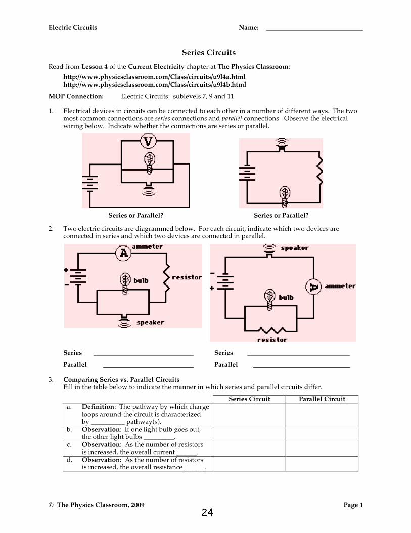
MOP Connection: Electric Circuits: sublevels 7, 9 and 11 1. Electrical devices in circuits can be connected to each other in a number of different ways. The two
most common connections are series connections and parallel connections. Observe the electrical wiring below. Indicate whether the connections are series or parallel.
Series or Parallel? Series or Parallel?
2. Two electric circuits are diagrammed below. For each circuit, indicate which two devices are connected in series and which two devices are connected in parallel.
Series
Parallel
Series
Parallel 3. Comparing Series vs. Parallel Circuits Fill in the table below to indicate the manner in which series and parallel circuits differ.
Series Circuit Parallel Circuit a. Definition: The pathway by which charge
loops around the circuit is characterized by __________ pathway(s).
b. Observation: If one light bulb goes out, the other light bulbs _________.
c. Observation: As the number of resistors is increased, the overall current ______.
d. Observation: As the number of resistors is increased, the overall resistance ______.

Electric Circuits
© The Physics Classroom, 2009 Page 2
4. The following diagrams represent circuits consisting of two electrical devices connected in series. For each diagram, fill in the blanks to show the voltage drop across the designated device.
5. Consider the following two diagrams of series circuits. For each diagram, use arrows to indicate the direction of the conventional current. Then, make comparisons of the voltage and the current at the designated points for each diagram.
VA _____ VG VA _____ VF (>,<, or =) (>,<, or =)
VB _____ VC VB _____ VC (>,<, or =) (>,<, or =)
VB _____ VF VD _____ VF (>,<, or =) (>,<, or =)
IA _____ IG IA _____ IF (>,<, or =) (>,<, or =)
5. Express your understanding of equivalent resistance by filling in the blanks.
Having two 4-Ω resistors in series is equivalent to having one _____-Ω resistor.
Having three 4-Ω resistors in series is equivalent to having one _____-Ω resistor.
Having four 4-Ω resistors in series is equivalent to having one _____-Ω resistor.
6. TRUE or FALSE:
Three light bulbs are connected in series. The filament of one of the light bulbs burns out. The remaining two light bulbs will still be lit; yet, their brightness will be noticeably less.

From http://www.physicsclassroom.com/Physics-Interactives Name:
©The Physics Classroom, All Rights Reserved This document should NOT appear on other websites.
DC Circuit Builder – Series Circuit
Goal: To analyze mathematical relationships between quantities for series circuits.
Getting Ready: Using your computer, tablet or phone and navigate to:
http://goo.gl/M4Ewmh
Tap or click the link to open the DC Circuit Builder. Once opened, select the pencil icon and use the tools (at the bottom of the screen) to build a circuit. Simply select a bulb, resistor, wire or ammeter (the rectangular box) and tap or click in the workspace where you wish it to be located. You’ll get the hang of it quite quickly. Note that the electric potential values are listed on the diagram at the corner of every square on the grid. Current values are listed on the ammeters. To change a battery voltage or a resistor value, select the second icon at the bottom of the screen; a magnifying glass appears above the circuit element. Adjust the voltage or the resistance using the up/down arrows next to the digital meter. Build, Measure, Analyze: Build the circuit shown with three resistors, four ammeters and a battery. Determine the values of current (amps) and electric pressure (volts) at the indicated locations.
1. For resistors 1, 2, and 3 and for the battery (B), calculate the electric potential difference and fill in the table below.
Element Electric Potential Difference (∆V) Current (I) Resistance (R)
B -- 1 2 3
V = _____ Volts
I = ______ Amps
I = ______ Amps
I = ______ Amps
V = _____ Volts
V = _____ Volts
I = ______ Amps
1
2
3
B
V = _____ Volts

©The Physics Classroom, All Rights Reserved This document should NOT appear on other websites.
2. How does the current in each resistor (I1, I2, I3) compare to one another and to the current in the battery (IB)?
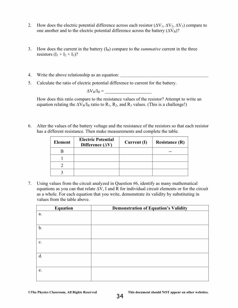
3. How does the electric potential difference across the battery (∆VB) compare to the summative electric potential differences of the three resistors (∆V1 + ∆V2 + ∆V3)?
4. Write the above relationship as an equation:
5. Calculate the ratio of electric potential difference to current for the battery.
∆VB/IB = ____________________
How does this ratio compare to the resistance values of the resistor? Attempt to write an equation relating the ∆VB/IB ratio to R1, R2, and R3 values.
6. Alter the values of the battery voltage and the resistance of the resistors so that each resistor
has a different resistance. Then make measurements and complete the table.
Element Electric Potential Difference (∆V) Current (I) Resistance (R)
B -- 1 2 3
7. Using values from the circuit analyzed in Question #6, identify as many mathematical
equations as you can that relate ∆V, I and R for individual circuit elements or for the circuit as a whole. For each equation that you write, demonstrate its validity by substituting in values from the table above.
Equation Demonstration of Equation’s Validity a.
b.
c.
d.
e.

Electric Circuits Name:
© The Physics Classroom, 2009 Page 3
7. Analyze the following circuit and determine the equivalent or total resistance. Then determine the current at the ammeter location.
Rtot = Rtot =
I = I =
8. For the following diagrams, utilize the concept of equivalent resistance and Ohm's Law in order to fill in the blank.
Ω
V

Worksheet: Parallel Circuit Problems - Episode904 Name _______________
PHYSICSFundamentals © 2004, GPB
9-14
Remember that in a parallel circuit: x the current in the branches of the circuit (is the same, adds up). x the voltage drops across each branch (is the same, adds up to) the total voltage. x to calculate total resistance, (add, use reciprocals).
Req = _____ IT = _____ V1 = _____ V2= _____ I1 = _____ I2 = _____
Req = _____ IT = _____ VT = _____ V1 = _____ I1 = _____ I2 = _____
V1 = _____ V2= _____ R1 = _____ R2 = _____ Req = _____ I1 = ____ I2 = ____ IT = ____
Req = _____ IT = _____ V1 = _____ V2 = _____ V3 = _____ I1 = _____ I2 = _____ I3 = _____
V1 = _____ V2= _____ IT = _____ I1 = _____ I2 = _____
R2= _____ Req = _____
V1 = _____ VT = _____ I1 = _____ I2 = _____ Req = _____ IT = _____
R2 6:
R3 12:
4a
R1 = 20: R2 = 20:
R R2 6:
R3 12:
40v R1 = 5: R2 = 20: R3 = 4:
6v
2a
R1 R2
1a
R2 6:
R3 12:
24v R1 = 12: R2 = 24:
R2 6:
R3 12:
12v R1 = 12: R2
3a R2 6:
R3 12:
R1 = 10: R2 = 15:
30v

Electric Circuits Name:
© The Physics Classroom, 2009 Page 1
Parallel Circuits
Read from Lesson 4 of the Current Electricity chapter at The Physics Classroom:
http://www.physicsclassroom.com/Class/circuits/u9l4a.html http://www.physicsclassroom.com/Class/circuits/u9l4c.html
MOP Connection: Electric Circuits: sublevels 8, 10 and 11
Review: 1. A circuit in which all charge follows a single pathway is a ____ circuit; a circuit in which charge
follows multiple pathways is a ____ circuit. a. series, parallel b. parallel, series 2. For a parallel circuit: as the number of resistors being used within the same parallel circuit increases,
the overall resistance value _____________________________ (increases, decreases) and the overall current value _____________________________ (increases, decreases).
3. Household circuits are connected in parallel so that _____. Select all that apply. a. houses get the same effect with less current and thus save on energy costs b. the turning off of one appliance does not result in the shut down of others c. the hazard of electrocution and overheating of circuits is avoided Water Analogy: 4. When the water flow (or charge flow) is divided into two or more separate pathways (as in a parallel
circuit) the sum of the current in each individual pathway equals the total current. Utilize this principle to fill in the blanks in the following two diagrams. The meters in the diagram are measuring water flow rates in gallons per minute ("gpm").
5. Apply the same principle to fill in the blanks in the following diagrams for charge flow (i.e., current) through a parallel circuit.
Electric Circuits
© The Physics Classroom, 2009 Page 2
The Staircase Analogy Electric charge dividing into multiple pathways in a parallel circuit is analogous to people walking down stairs which divide up into separate paths.
Imagine being at a large shopping mall; you are descending a rather wide stairway when all of a sudden it breaks up into several smaller stairways. Being in a hurry, you scan the different pathways down the stairs to see which path is least crowded. You finally decide that the left stairway is least crowded and make a "dash" towards it. You know that your "flow rate" will be greatest along the stairway with the least resistance. When the "people flow" divides up into multiple pathways, each pathway has the same change in height (or same gravitational potential drop); yet, the pathway that offers the least resistance will have the greatest flow rate.
In an analogous manner, as charge flow divides up into multiple pathways in a parallel circuit, each pathway has the same electric potential drop; yet, the pathway with the least resistance will have the greatest rate of charge flow (i.e., current).
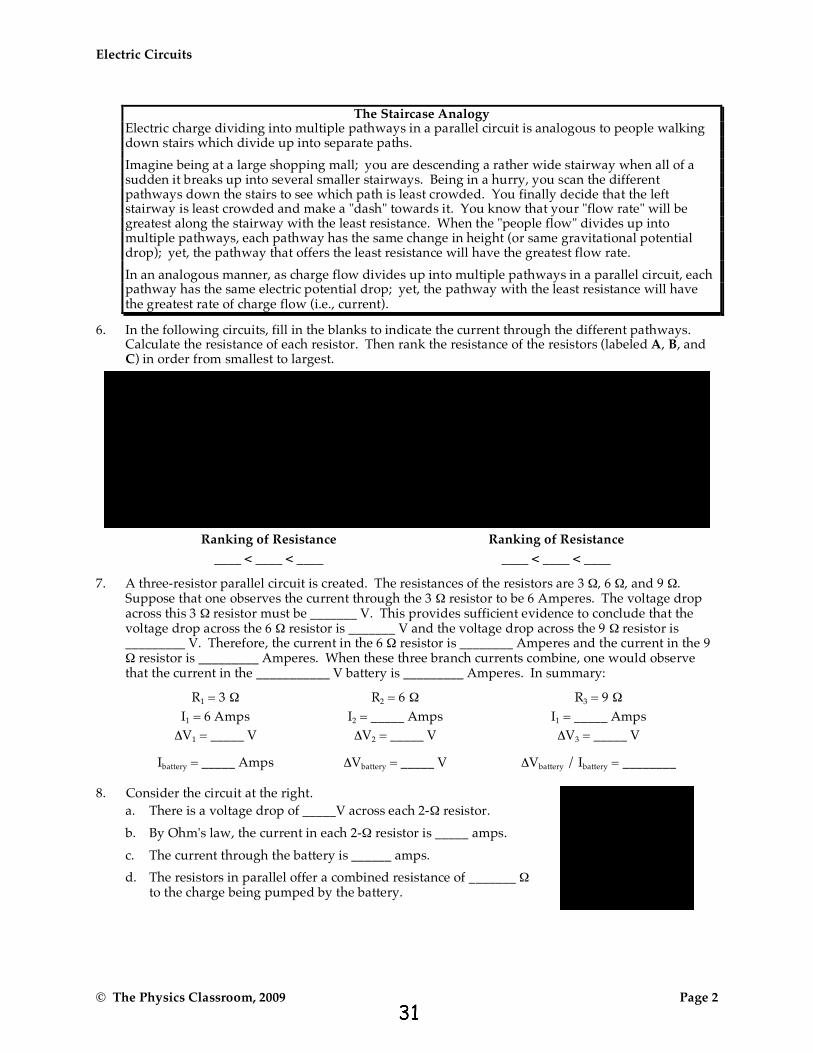
6. In the following circuits, fill in the blanks to indicate the current through the different pathways. Calculate the resistance of each resistor. Then rank the resistance of the resistors (labeled A, B, and C) in order from smallest to largest.
Ranking of Resistance Ranking of Resistance
____ < ____ < ____ ____ < ____ < ____
7. A three-resistor parallel circuit is created. The resistances of the resistors are 3 Ω, 6 Ω, and 9 Ω. Suppose that one observes the current through the 3 Ω resistor to be 6 Amperes. The voltage drop across this 3 Ω resistor must be _______ V. This provides sufficient evidence to conclude that the voltage drop across the 6 Ω resistor is _______ V and the voltage drop across the 9 Ω resistor is _________ V. Therefore, the current in the 6 Ω resistor is ________ Amperes and the current in the 9 Ω resistor is _________ Amperes. When these three branch currents combine, one would observe that the current in the ___________ V battery is _________ Amperes. In summary:
R1 = 3 Ω R2 = 6 Ω R3 = 9 Ω
I1 = 6 Amps I2 = _____ Amps I1 = _____ Amps
ΔV1 = _____ V ΔV2 = _____ V ΔV3 = _____ V
Ibattery = _____ Amps ΔVbattery = _____ V ΔVbattery / Ibattery = ________ 8. Consider the circuit at the right.
a. There is a voltage drop of _____V across each 2-Ω resistor.
b. By Ohm's law, the current in each 2-Ω resistor is _____ amps.
c. The current through the battery is ______ amps.
d. The resistors in parallel offer a combined resistance of _______ Ω to the charge being pumped by the battery.
Electric Circuits Name:
© The Physics Classroom, 2009 Page 3
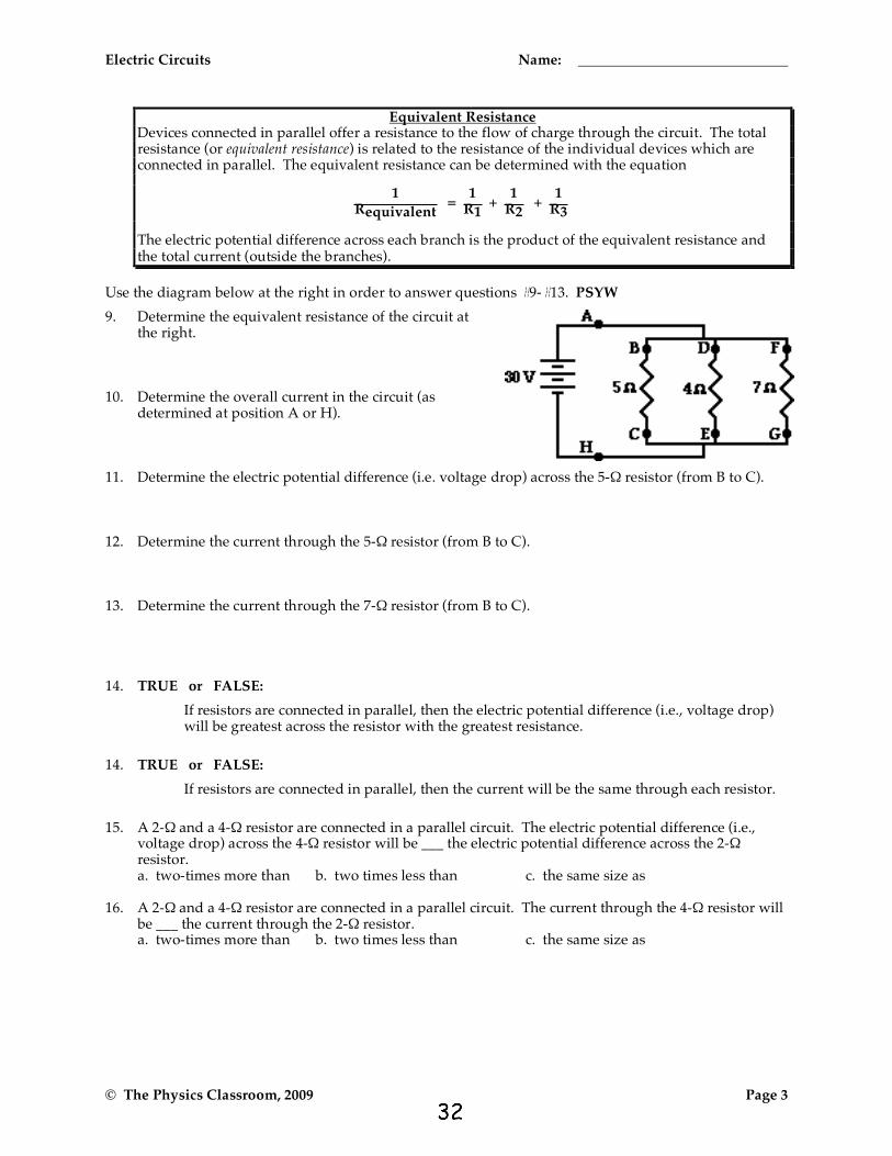
Equivalent Resistance Devices connected in parallel offer a resistance to the flow of charge through the circuit. The total resistance (or equivalent resistance) is related to the resistance of the individual devices which are connected in parallel. The equivalent resistance can be determined with the equation
1Requivalent
= 1
R1 +
1R2
+ 1
R3
The electric potential difference across each branch is the product of the equivalent resistance and the total current (outside the branches).
Use the diagram below at the right in order to answer questions #9-#13. PSYW
9. Determine the equivalent resistance of the circuit at the right.
10. Determine the overall current in the circuit (as
determined at position A or H). 11. Determine the electric potential difference (i.e. voltage drop) across the 5-Ω resistor (from B to C). 12. Determine the current through the 5-Ω resistor (from B to C). 13. Determine the current through the 7-Ω resistor (from B to C). 14. TRUE or FALSE:
If resistors are connected in parallel, then the electric potential difference (i.e., voltage drop) will be greatest across the resistor with the greatest resistance.
14. TRUE or FALSE:
If resistors are connected in parallel, then the current will be the same through each resistor.
15. A 2-Ω and a 4-Ω resistor are connected in a parallel circuit. The electric potential difference (i.e., voltage drop) across the 4-Ω resistor will be ___ the electric potential difference across the 2-Ω resistor.
a. two-times more than b. two times less than c. the same size as 16. A 2-Ω and a 4-Ω resistor are connected in a parallel circuit. The current through the 4-Ω resistor will
be ___ the current through the 2-Ω resistor. a. two-times more than b. two times less than c. the same size as

From http://www.physicsclassroom.com/Physics-Interactives Name:
©The Physics Classroom, All Rights Reserved This document should NOT appear on other websites.
DC Circuit Builder – Parallel Circuit
Goal: To analyze mathematical relationships between quantities for parallel circuits.
Getting Ready: Using your computer, tablet or phone and navigate to:
http://goo.gl/M4Ewmh
Tap or click the link to open the DC Circuit Builder. Once opened, select the pencil icon and use the tools (at the bottom of the screen) to build a circuit. Simply select a bulb, resistor, wire or ammeter (the rectangular box) and tap or click in the workspace where you wish it to be located. You’ll get the hang of it quite quickly. Note that the electric potential values are listed on the diagram at the corner of every square on the grid. Current values are listed on the ammeters. To change a battery voltage or a resistor value, select the second icon at the bottom of the screen; a magnifying glass appears above the circuit element. Adjust the voltage or the resistance using the up/down arrows next to the digital meter. Build, Measure, Analyze: Build the circuit shown with three resistors, four ammeters and a battery. Determine the values of current (amps) and electric pressure (volts) at the indicated locations.
1. For resistors 1, 2, and 3 and for the battery (B), calculate the electric potential difference and fill in the table below.
Element Electric Potential Difference (∆V) Current (I) Resistance (R)
B -- 1 2 3
V = _____ Volts
I = ______ Amps
V = _____ Volts
I = _____ Amps I = _____ Amps I = _____ Amps
V = _____ Volts V = _____ Volts V = _____ Volts
V = _____ Volts V = _____ Volts V = _____ Volts
1 2 3 B
©The Physics Classroom, All Rights Reserved This document should NOT appear on other websites.
2. How does the electric potential difference across each resistor (∆V1, ∆V2, ∆V3) compare to one another and to the electric potential difference across the battery (∆VB)?
3. How does the current in the battery (IB) compare to the summative current in the three
resistors (I1 + I2 + I3)? 4. Write the above relationship as an equation:
5. Calculate the ratio of electric potential difference to current for the battery.
∆VB/IB = ____________________
How does this ratio compare to the resistance values of the resistor? Attempt to write an equation relating the ∆VB/IB ratio to R1, R2, and R3 values. (This is a challenge!)
6. Alter the values of the battery voltage and the resistance of the resistors so that each resistor
has a different resistance. Then make measurements and complete the table.
Element Electric Potential Difference (∆V) Current (I) Resistance (R)
B -- 1 2 3
7. Using values from the circuit analyzed in Question #6, identify as many mathematical
equations as you can that relate ∆V, I and R for individual circuit elements or for the circuit as a whole. For each equation that you write, demonstrate its validity by substituting in values from the table above.
Equation Demonstration of Equation’s Validity a.
b.
c.
d.
e.
Electric Circuits
© The Physics Classroom, 2009 Page 4
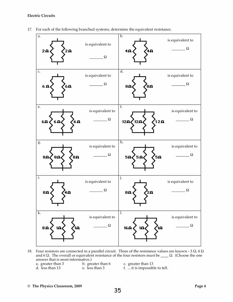
17. For each of the following branched systems, determine the equivalent resistance.
a.
is equivalent to
_______ Ω
b.
is equivalent to
_______ Ω
c.
is equivalent to
_______ Ω
d.
is equivalent to
_______ Ω
e.
is equivalent to
_______ Ω
f.
is equivalent to
_______ Ω
g.
is equivalent to
_______ Ω
h.
is equivalent to
_______ Ω
i.
is equivalent to
_______ Ω
j.
is equivalent to
_______ Ω
k.
is equivalent to
_______ Ω
l.
is equivalent to
_______ Ω
18. Four resistors are connected in a parallel circuit. Three of the resistance values are known - 3 Ω, 4 Ω and 6 Ω. The overall or equivalent resistance of the four resistors must be ____ Ω. (Choose the one answer that is most informative.)
a. greater than 3 b. greater than 6 c. greater than 13 d. less than 13 e. less than 3 f. ... it is impossible to tell.
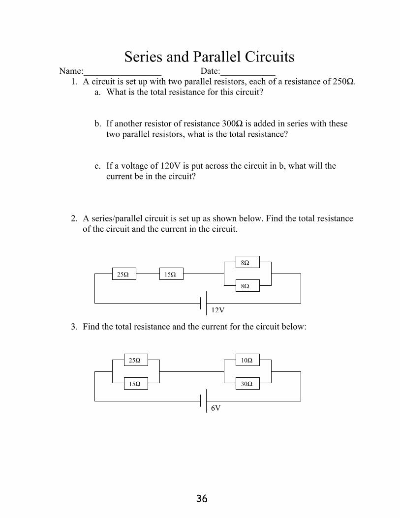
Series and Parallel Circuits Name:_________________ Date:____________
1. A circuit is set up with two parallel resistors, each of a resistance of 250Ω. a. What is the total resistance for this circuit?
b. If another resistor of resistance 300Ω is added in series with these two parallel resistors, what is the total resistance?
c. If a voltage of 120V is put across the circuit in b, what will the current be in the circuit?
2. A series/parallel circuit is set up as shown below. Find the total resistance of the circuit and the current in the circuit.
3. Find the total resistance and the current for the circuit below:
25ΩΩ
15Ω
8Ω
8Ω
12V
25ΩΩ
15Ω
10Ω
30Ω
6V

4. Find the total resistance and the current for the circuit on the back:
5. Find the total resistance and the voltage for the circuit below:
6. Find the total resistance and the voltage for the circuit below:
45ΩΩ
8Ω
15Ω
3Ω
Total current in the circuit = 2.4 A
25ΩΩ
15Ω
10Ω
30Ω
Total current in the circuit = 2 A
10ΩΩ
5Ω
6Ω
8Ω
18V
From The Physics Classroom’s Physics Interactive http://www.physicsclassroom.com
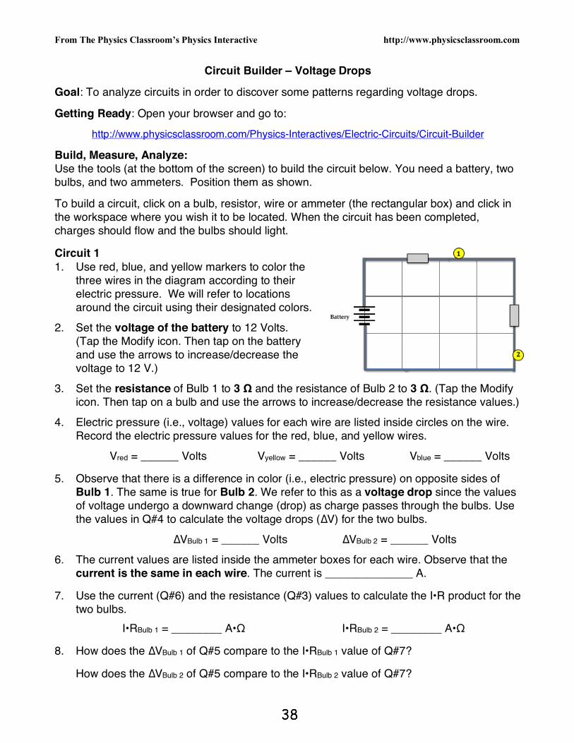
Circuit Builder – Voltage Drops
Goal: To analyze circuits in order to discover some patterns regarding voltage drops.
Getting Ready: Open your browser and go to:
http://www.physicsclassroom.com/Physics-Interactives/Electric-Circuits/Circuit-Builder
Build, Measure, Analyze: Use the tools (at the bottom of the screen) to build the circuit below. You need a battery, two bulbs, and two ammeters. Position them as shown.
To build a circuit, click on a bulb, resistor, wire or ammeter (the rectangular box) and click in the workspace where you wish it to be located. When the circuit has been completed, charges should flow and the bulbs should light. Circuit 1 1. Use red, blue, and yellow markers to color the
three wires in the diagram according to their electric pressure. We will refer to locations around the circuit using their designated colors.
2. Set the voltage of the battery to 12 Volts. (Tap the Modify icon. Then tap on the battery and use the arrows to increase/decrease the voltage to 12 V.)
3. Set the resistance of Bulb 1 to 3 Ω and the resistance of Bulb 2 to 3 Ω. (Tap the Modify icon. Then tap on a bulb and use the arrows to increase/decrease the resistance values.)
4. Electric pressure (i.e., voltage) values for each wire are listed inside circles on the wire. Record the electric pressure values for the red, blue, and yellow wires.
Vred = ______ Volts Vyellow = ______ Volts Vblue = ______ Volts 5. Observe that there is a difference in color (i.e., electric pressure) on opposite sides of
Bulb 1. The same is true for Bulb 2. We refer to this as a voltage drop since the values of voltage undergo a downward change (drop) as charge passes through the bulbs. Use the values in Q#4 to calculate the voltage drops (∆V) for the two bulbs.
∆VBulb 1 = ______ Volts ∆VBulb 2 = ______ Volts
6. The current values are listed inside the ammeter boxes for each wire. Observe that the current is the same in each wire. The current is ______________ A.
7. Use the current (Q#6) and the resistance (Q#3) values to calculate the I•R product for the
two bulbs.
I•RBulb 1 = ________ A•Ω I•RBulb 2 = ________ A•Ω 8. How does the ∆VBulb 1 of Q#5 compare to the I•RBulb 1 value of Q#7? How does the ∆VBulb 2 of Q#5 compare to the I•RBulb 2 value of Q#7?
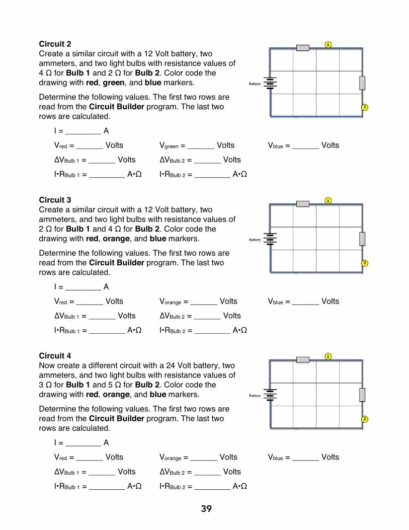
Circuit 2 Create a similar circuit with a 12 Volt battery, two ammeters, and two light bulbs with resistance values of 4 Ω for Bulb 1 and 2 Ω for Bulb 2. Color code the drawing with red, green, and blue markers.
Determine the following values. The first two rows are read from the Circuit Builder program. The last two rows are calculated.
I = ________ A
Vred = ______ Volts Vgreen = ______ Volts Vblue = ______ Volts
∆VBulb 1 = ______ Volts ∆VBulb 2 = ______ Volts
I•RBulb 1 = ________ A•Ω I•RBulb 2 = ________ A•Ω Circuit 3 Create a similar circuit with a 12 Volt battery, two ammeters, and two light bulbs with resistance values of 2 Ω for Bulb 1 and 4 Ω for Bulb 2. Color code the drawing with red, orange, and blue markers.
Determine the following values. The first two rows are read from the Circuit Builder program. The last two rows are calculated.
I = ________ A
Vred = ______ Volts Vorange = ______ Volts Vblue = ______ Volts
∆VBulb 1 = ______ Volts ∆VBulb 2 = ______ Volts
I•RBulb 1 = ________ A•Ω I•RBulb 2 = ________ A•Ω Circuit 4 Now create a different circuit with a 24 Volt battery, two ammeters, and two light bulbs with resistance values of 3 Ω for Bulb 1 and 5 Ω for Bulb 2. Color code the drawing with red, orange, and blue markers.
Determine the following values. The first two rows are read from the Circuit Builder program. The last two rows are calculated.
I = ________ A
Vred = ______ Volts Vorange = ______ Volts Vblue = ______ Volts
∆VBulb 1 = ______ Volts ∆VBulb 2 = ______ Volts
I•RBulb 1 = ________ A•Ω I•RBulb 2 = ________ A•Ω

Circuit 5 Create Circuit 5 using a 36 Volt battery, two ammeters, and two light bulbs with resistance values of 12 Ω for Bulb 1 and 6 Ω for Bulb 2. Color code the drawing with red, green, and blue markers. Determine the following values. The first two rows are read from the Circuit Builder program. The last two rows are calculated.
I = ________ A
Vred = ______ Volts Vgreen = ______ Volts Vblue = ______ Volts
∆VBulb 1 = ______ Volts ∆VBulb 2 = ______ Volts
I•RBulb 1 = ________ A•Ω I•RBulb 2 = ________ A•Ω Circuit 6 Circuit 6 will contain three bulbs. Build it as shown and as described. Use a 24 Volt battery, three ammeters, and three light bulbs with resistance values of 3 Ω for Bulb 1 and 4 Ω for Bulb 2 and 5 Ω for Bulb 3. Color code the drawing with red, orange, green, and blue markers.
Determine the following values. The first two rows are read from the Circuit Builder program. The last two rows are calculated.
I = ________ A
Vred = ______ V Vorange = ______ V Vgreen = ______ V Vblue = ______ V
∆VBulb 1 = _____ V ∆VBulb 2 = _____ V ∆VBulb 3 = _____ V
I•RBulb 1 = ______ A•Ω I•RBulb 2 = ______ A•Ω I•RBulb 3 = ______ A•Ω Circuit 7 Create Circuit 7 using a 24 Volt battery, three ammeters, and three light bulbs with resistance values of 1 Ω for Bulb 1 and 2 Ω for Bulb 2 and 3 Ω for Bulb 3. Color code the drawing with red, orange, green, and blue markers. Determine the following values. The first two rows are read from the Circuit Builder program. The last two rows are calculated.
I = ________ A
Vred = ______ V Vorange = ______ V Vgreen = ______ V Vblue = ______ V
∆VBulb 1 = _____ V ∆VBulb 2 = _____ V ∆VBulb 3 = _____ V
I•RBulb 1 = ______ A•Ω I•RBulb 2 = ______ A•Ω I•RBulb 3 = ______ A•Ω

Summary and Application: Conduct voltage drop analysis without using the program. Base answers on the patterns learned from analyzing Circuits 1 – 7.
1. Consider the 3-bulb circuit at the right. Color code the diagram with red, yellow, green, and blue markers. Suppose you know that …
Battery voltage = 12 V, Current = 2 A, and
R1 = 3 Ω R2 = 2 Ω R3 = 1 Ω Use I•R values to determine the values of electric
pressure for the four different wires: Vred = ______ V Vyellow = ______ V Vgreen = ______ V Vblue = ______ V 2. Consider the 5-bulb circuit at the right. It is not a series
circuit. Yet color coding and voltage drop fundamentals still apply. Color code the diagram with red, orange, yellow, green, and blue markers. Suppose you know that …
Battery voltage = 48 V, and
R1 = 4.0 Ω R2 = 12.0 Ω R3 = 4.0 Ω
R4 = 8.0 Ω R5 = 2.0 Ω
Because of how the circuit is built, the current is not the same in all five bulbs like it would be in series circuits. The current (I) values at the various bulb locations are …
I1 = 4.0 A I2 = 2.0 A I3 = 2.0 A I4 = 2.0 A I5 = 4.0 A
Use the current and resistance values to calculate the voltage drops for each bulb.
∆V1 = _____ V ∆V2 = _____ V ∆V3 = _____ V ∆V4 = _____ V ∆V5 = _____ V Finally, use the voltage drop (∆V) values to calculate the electric pressure values for the
five different wires (referenced here by their colors):
Vred = ____ V Vorange = ____ V Vyellow = ____ V
Vgreen = ____ V Vblue = ____ V
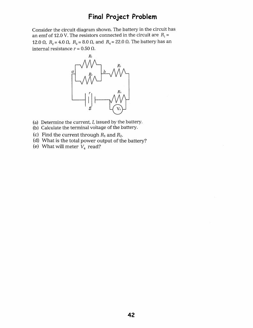
FreeResponseQuestions#1.
#2.