unit controller version 8 manual rev 2.0 hvac and cent v8
TRANSCRIPT
SAFETY WARNINGOnly qualified personnel should install and service the equipment.The installation, starting up, and servicing of heating, ventilating, and air-
conditioning equipment can be hazardous and requires specific knowledge and training. Improperly installed, adjusted or altered equipment
by an unqualified person could result in death or serious injury.When working on the equipment, observe all precautions in the literature and
on the tags, stickers, and labels that are attached to the equipment.
Unit Controller Version 8 Manual Rev. 2.0
HVAC and CENT V8 Software
Installation, Operation,
and Maintenance
CGWQ-SVX02A-ENMarch 2014
Introduction
Read this manual thoroughly before operating or servicingthis unit.
Warnings, Cautions, and Notices
Safety advisories appear throughout this manual asrequired.Your personal safety and the proper operation ofthis machine depend upon the strict observance of theseprecautions.
Important Environmental Concerns
Scientific research has shown that certain man-madechemicals can affect the earth’s naturally occurringstratospheric ozone layer when released to theatmosphere. In particular, several of the identifiedchemicals that may affect the ozone layer are refrigerantsthat contain Chlorine, Fluorine and Carbon (CFCs) andthose containing Hydrogen, Chlorine, Fluorine andCarbon (HCFCs). Not all refrigerants containing thesecompounds have the same potential impact to theenvironment.Trane advocates the responsible handling ofall refrigerants-including industry replacements for CFCssuch as HCFCs and HFCs.
Important Responsible Refrigerant Practices
Trane believes that responsible refrigerant practices areimportant to the environment, our customers, and the airconditioning industry. All technicians who handlerefrigerants must be certified.The Federal Clean Air Act(Section 608) sets forth the requirements for handling,reclaiming, recovering and recycling of certainrefrigerants and the equipment that is used in theseservice procedures. In addition, some states ormunicipalities may have additional requirements thatmust also be adhered to for responsible management ofrefrigerants. Know the applicable laws and follow them.
The three types of advisories are defined as follows:
WARNINGIndicates a potentially hazardoussituation which, if not avoided, couldresult in death or serious injury.
CAUTIONsIndicates a potentially hazardoussituation which, if not avoided, couldresult in minor or moderate injury. Itcould also be used to alert againstunsafe practices.
NOTICE: Indicates a situation that could result inequipment or property-damage onlyaccidents.
WARNING
Proper Field Wiring and GroundingRequired!
Failure to follow code could result in death or seriousinjury. All field wiring MUST be performed by qualifiedpersonnel. Improperly installed and grounded fieldwiring poses FIRE and ELECTROCUTION hazards.Toavoid these hazards, you MUST follow requirements forfield wiring installation and grounding as described inNEC and your local/state electrical codes.
WARNING
Personal Protective Equipment (PPE)Required!
Installing/servicing this unit could result in exposure toelectrical, mechanical and chemical hazards.
• Before installing/servicing this unit, technicians
MUST put on all PPE required for the work being
undertaken (Examples; cut resistant gloves/sleeves,
butyl gloves, safety glasses, hard hat/bump cap, fall
protection, electrical PPE and arc flash clothing).
ALWAYS refer to appropriate Material Safety Data
Sheets (MSDS)/Safety Data Sheets (SDS) and OSHA
guidelines for proper PPE.
• When working with or around hazardous chemicals,
ALWAYS refer to the appropriate MSDS/SDS and
OSHA/GHS (Global Harmonized System of
Classification and Labelling of Chemicals) guidelines
for information on allowable personal exposure
levels, proper respiratory protection and handling
instructions.
• If there is a risk of energized electrical contact, arc, or
flash, technicians MUST put on all PPE in accordance
with OSHA, NFPA 70E, or other country-specific
requirements for arc flash protection, PRIOR to
servicing the unit. NEVER PERFORM ANY
SWITCHING, DISCONNECTING, OR VOLTAGE
TESTING WITHOUT PROPER ELECTRICAL PPE AND
ARC FLASH CLOTHING. ENSURE ELECTRICAL
METERS AND EQUIPMENT ARE PROPERLY RATED
FOR INTENDED VOLTAGE.
Failure to follow instructions could result in death orserious injury.
© 2014Trane All rights reserved CGWQ-SVX02A-EN
Introduction
Copyright
This document and the information in it are the property ofTrane, and may not be used or reproduced in whole or inpart without written permission.Trane reserves the rightto revise this publication at any time, and to make changesto its content without obligation to notify any person ofsuch revision or change.
Trademarks
All trademarks referenced in this document are thetrademarks of their respective owners.
Revision History
CGWQ-SVX02A-EN
New release.
Note: This manual has been edited by NappsTechnologyto reduce setpoint and other information that is notrelevant to a Napps/Trane-branded Chiller. A freeunedited version is available for download atwww.MCScontrols.com
Please contact with questions:
NappsTechnology Corp. 903-758-2900
CGWQ-SVX02A-EN 3
Table of Contents
Warnings, Cautions, and Notices . . . . . . . . 2
Introduction . . . . . . . . . . . . . . . . . . . . . . . . . . . . . 6
Introduction to Unit Controller HVAC andCENT V8 Software . . . . . . . . . . . . . . . . . . . . . 6
Unit Controller V8 SoftwareControl Point Capacity . . . . . . . . . . . . . . . . . . 6
Unit Controller Hardware Supportedby Unit Controller V8 Software . . . . . . . . . . 6
About this Manual . . . . . . . . . . . . . . . . . . . . . 6
About the Unit Controller . . . . . . . . . . . . . . . 7
PC Support Software for Unit Controller . . 7
MCS 485 Network . . . . . . . . . . . . . . . . . . . . . 7
MCS Ethernet Port . . . . . . . . . . . . . . . . . . . . . 7
MCS 485 Communications . . . . . . . . . . . . . . . 8
Requirements for PC Software . . . . . . . . . . . 10
Unit Controller Control Zone Logic . . . . . . . 11
Common Definitions . . . . . . . . . . . . . . . . . . 11
Example of a Systemwith 4 Scroll Compressors . . . . . . . . . . . . . 11
Unit Controller Display Summary . . . . . . . . 12
Unit Controller Keypad and Display . . . . . 12
Unit Status . . . . . . . . . . . . . . . . . . . . . . . . . . 12
Unit Tonnage and KW Information . . . . . . 12
Compressor Status . . . . . . . . . . . . . . . . . . . 13
HVAC STATUS Display (MCS-Connect) . . 13
Unit Controller Control States . . . . . . . . . . . . 15
Unit Control States (number) . . . . . . . . . . . 15
Compressor Control States . . . . . . . . . . . . 16
Setpoint Definitions . . . . . . . . . . . . . . . . . . . . . 18
Setpoint Types . . . . . . . . . . . . . . . . . . . . . . . 18
Authorization Function . . . . . . . . . . . . . . . . . . 19
Standard Control Options . . . . . . . . . . . . . . . 20
General Options . . . . . . . . . . . . . . . . . . . . . . 20
Chilled Water Reset . . . . . . . . . . . . . . . . . . . 20
On/Off Switches . . . . . . . . . . . . . . . . . . . . . . 20
Chilled Water Pump Control . . . . . . . . . . . 20
Low and High Ambient Shutdown . . . . . . 21
Compressor Auto Rotation . . . . . . . . . . . . . 21
Compressor Anti-Cycle Logic . . . . . . . . . . . 21
Alarm Relay Outputs . . . . . . . . . . . . . . . . . . .21
Operating Schedules . . . . . . . . . . . . . . . . . . .21
Compressor Lead and Rotation . . . . . . . . . .21
Condenser Control Logic . . . . . . . . . . . . . . . . .22
RO Step Condenser Cut In – Out Logic . . .22
RO Step Condenser withVariable Speed Fan or Damper . . . . . . . . . .22
Unit Controller Alarms and Safeties . . . . . . .24
Information Only Alarms . . . . . . . . . . . . . . .24
Unit Controller System Alarms . . . . . . . . . .25
Setpoint Safety Alarms . . . . . . . . . . . . . . . . .25
Unit Controller Unit Control StatesQuick Reference . . . . . . . . . . . . . . . . . . . . . . . . .27
Unit Controller Compressor Control StatesQuick Reference . . . . . . . . . . . . . . . . . . . . . . . . .28
OEM Factory Checkout Procedure . . . . . . . . .29
Visual Check . . . . . . . . . . . . . . . . . . . . . . . . . .29
MCS Power On(Compressor Power off) . . . . . . . . . . . . . . . .29
Unit Controller Keypad DisplayQuick Reference . . . . . . . . . . . . . . . . . . . . . . . . .30
Unit Controller Hardware Rev 6Quick Reference Sheet . . . . . . . . . . . . . . . . . . .31
Unit Controller Hardware SI16/AO4Quick Reference . . . . . . . . . . . . . . . . . . . . . . . . .32
Unit Controller Hardware RO10Quick Reference . . . . . . . . . . . . . . . . . . . . . . . . .33
Unit Controller Quick Reference Sheet(Temp and Humidity) . . . . . . . . . . . . . . . . . . . .34
Unit Controller Quick Reference Sheet(PSI, CT and Digital) . . . . . . . . . . . . . . . . . . . . .35
Unit Controller TroubleshootingQuick Reference Sheet . . . . . . . . . . . . . . . . . . .37
BMS Communication Protocols . . . . . . . . . . .39
Sensor Input (SI) Points . . . . . . . . . . . . . . . .39
Relay Output (RO) Points . . . . . . . . . . . . . . .39
Analog Output Points . . . . . . . . . . . . . . . . . .39
Setpoints . . . . . . . . . . . . . . . . . . . . . . . . . . . . .39
Chiller/Compressor States . . . . . . . . . . . . . .40
Other Points . . . . . . . . . . . . . . . . . . . . . . . . . .40
Network Inputs to Unit Controller . . . . . . . .40
4 CGWQ-SVX02A-EN
MCS Capacity Control State Chart . . . . . . 41
MCS Compressor Control State Chart . . . 41
Unit Controller BMS Connections . . . . . . . . 42
Unit Controller BMS Protocols Settings . . 43
Setpoints for Unit ControllerHVAC V8 Software . . . . . . . . . . . . . . . . . . . . . . 45
CGWQ-SVX02A-EN 5
Introduction
Introduction to Unit Controller
HVAC and CENT V8 Software
Unit Controller V8 software has been designed to controlmany different types of compressors of both fixed andvariable capacity, as well as many additional features.Supported control options include multiple liquid linesolenoids, electronic expansion valves (EXVs), liquidinjection,economizers,hot gasbypass, variable frequencydrives for compressors (VFDs), digital scrolls, and manymore.
Applications vary from control of a single compressor tocomplex multiple compressor systems. In all applications,however, safety and operating efficiency is of primaryimportance.The controller interface is made to beinformative and meaningful, with built-in logic to preventunsafe conditions from occurring.This helps reduce oreven completely eliminate nuisance alarms.
There are two types of Unit Controller software describedin this manual:
• HVAC V8:This software supports all types ofcompressors except centrifugals. It supports theconfiguration type 106 Chiller V8 CFG, as well as 109Loop Control CFG. If this software is loaded into a UnitController with a different type of configuration file, aninvalid configuration type message will be generated.
• CENT V8:This software supports only rifugalcompressors, and requires a configuration type 119CENT MAG CFG. If this software is loaded into a UnitController with a different type of configuration file, aninvalid configuration type message will be generated.
These software types are very similar and most topics willapply to both. However, if a topic applies only to one typeit will be labeled as either ‘only HVAC’ or ‘only CENT’.
Unit Controller V8 Software
Control Point Capacity
• Circuits (compressors) up to 20
• Steps per Compressor up to 4
• Relay Outputs up to 80
• Analog Outputs up to 20
• Sensor Inputs up to 80
• Setpoints 230
• Alarms 100
Unit Controller Hardware
Supported
by Unit Controller V8 Software
The following MCS boards can be connected together viathe MCS-I/O communications terminal block:
• MCS-Unit Controller (10 RO’s, 12 SI’s, 4 Digital SI’s, and4 AO’s)
• MCS-I/O (8 RO - 8 SI - 1 AO with I/O 7.00-C with a GAL5.0 chip)
• MCS-RO8 (8 RO)
• MCS-SI16 (16 SI)
• MCS-RO10 (10 RO)
• MCS-SI16-AO4 (16 SI and 4 AO)
The versatility of the Unit Controller offers the user muchflexibility in configuring the controls in an economicalway.The limitation is not the number of boards but thetotal number of points.
About this Manual
The purpose of this manual is to document MCS’s V8software for the Unit Controller.This software requires aconfiguration type 11 in MCS-Config. Any other type ofconfiguration file will result in an invalid Config messageand the unit will not function.
This manual documents how the Unit Controller V8software functions. Since this is a large manual, it isstructured in logical sections for ease of reference.TheTable of Contents will guide you through the sections butyou are urged to read the entire manual.This will providean understanding of the capabilities of the Unit ControllerControl System and hopefully introduce other ways thatyou may benefit from the existing control strategies. QuickReference sheets and MCS Specification sheets areprovided in the appendixes.
A printed copy may be ordered, please refer to our PriceBook. A PDF copy of this manual may be down loadedfrom our web site at www.MCScontrols.com free ofcharge.
An approved OEM of MCS may make copies and / orchange any section of this manual to develop customdocumentation for a site where a Unit Controller isinstalled. In this way, MCS supports the documentationrequirements of individual customer sites.
Note: This manual has been edited by NappsTechnologyto reduce set point and other information that is notrelevant to aTrane-branded CGWQ/CCAQ Chiller.Afree unedited version is available for download atwww.MCScontrols.com
6 CGWQ-SVX02A-EN
Introduction
About the Unit Controller
The Unit Controller is a rugged microprocessor controllerdesigned for the harsh environment of the HVAC/Rindustry. It is designed to provide primary control withoutneeding mechanical controls. It will interface locally with anull modem serial cable, remotely through an Ethernetconnection, and also through building managementsystems.The Unit Controller offers a great deal offlexibility with adjustable setpoints and control optionsthat can be set prior to activating a system or even whenthe unit is operational.The Unit Controller is designed tosafeguard the system being controlled, eliminate the needfor manual intervention, and to provide a simple butmeaningful user interface.
PC Support Software for Unit
Controller
MCS-Connect provides both local and remotecommunications to the Unit Controller independent ofsoftware type. Local communications can be either via anRS485 or Ethernet connection.This program displays thestatus of the controller, and changes can be made to thesystem with proper authorization. Configuration files canbe transmitted to or received from a Unit Controller unit.The Unit Controller automatically performs historylogging and this program allows the data to be presentedin a useful graph form. A manual created in a PDF formatis available on our web site: www.MCScontrols.com, oravailable in other formats upon request.
This program uses the Microsoft Windows Help functionto assist the user.
MCS 485 Network
The MCS 485 Network can support up to 20 UnitControllers and their associated I/O boards. Access to thisnetwork can be local via RS 232 or Ethernet connection, orremotely via a 14.4K Baud modem.When using the dialupconnection through a modem there is no degradation inthe performance of the network.
Each Unit Controller in the network must be assigned aunique address in the configuration file.This address willbe the key in establishing communications with theappropriate Unit Controller system. It can be viewed orchanged from the LCD / keypad of the unit with Factoryauthorization.
Notes:
• RS 232 transmissions should not exceed 50’ in length.
• RS 485 transmissions should not exceed 1 milewithout a repeater.
MCS Ethernet Port
When connecting directly through the 100 MBPS Ethernetport on the Unit Controller from a PC it is necessary to usea crossover Ethernet cable.
CGWQ-SVX02A-EN 7
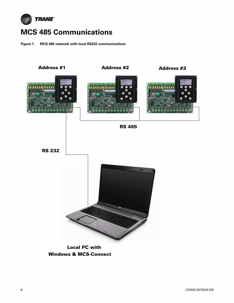
MCS 485 Communications
Figure 1. MCS 485 network with local RS232 communications
Address #1 Address #2 Address #3
RS 232
RS 485
Local PC withWindows & MCS-Connect
8 CGWQ-SVX02A-EN
MCS 485 Communications
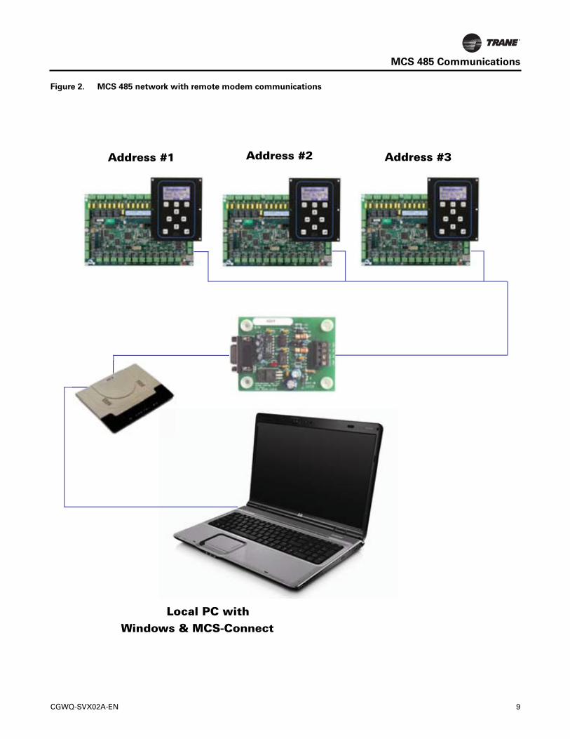
Figure 2. MCS 485 network with remote modem communications
Address #1 Address #2 Address #3
Local PC withWindows & MCS-Connect
CGWQ-SVX02A-EN 9
10 CGWQ-SVX02A-EN
Requirements for PC Software
To install and run the program we suggest the followingsystem requirements:
Minimum System Required to Run Program:
• Windows 2000 or higher
• Pentium processor
• 20 Gigabyte Available Hard Disk space
• Super VGA Display capable of displaying 256 colors
512 Megabytes RAM
CGWQ-SVX02A-EN 11
Unit Controller Control Zone Logic
The control strategy is designed to modulate thecompressor(s) capacity to maintain the control sensorreading within the specified control zone.To accomplishthis, the system will constantly monitor the control value,its rate of change, and position in relationship to thecontrol zone and make adjustments accordingly.
The strategies for a fixed step system, reciprocatingcompressor, reciprocating compressor with an inverter,variable (slide) step system, or a screw compressor are allslightly different.The variable step system allows forinfinite variations of capacity while the fixed step systemdoes not.
Common Definitions
Target
The control target is specified in setpoint #1.This will bethe base of developing the control zone.
Control Zone
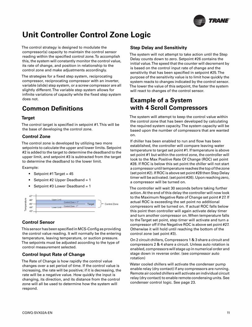
The control zone is developed by utilizing two moresetpoints to calculate the upper and lower limits. Setpoint#2 is added to the target to determine the deadband to theupper limit, and setpoint #3 is subtracted from the targetto determine the deadband to the lower limit.
Example:
• Setpoint #1Target = 45
• Setpoint #2 Upper Deadband = 1
• Setpoint #3 Lower Deadband = 1
Control Sensor
This sensor has been specified in MCS-Config as providingthe control value reading. It will normally be the enteringtemperature, leaving temperature, or suction pressure.The setpoints must be adjusted according to the type ofcontrol measurement selected.
Control Input Rate of Change
The Rate of Change is how rapidly the control valuechanges over a set period of time. If the control value isincreasing, the rate will be positive; if it is decreasing, therate will be a negative value. How quickly the input ischanging, its direction, and its distance from the controlzone will all be used to determine how the system willrespond.
Step Delay and Sensitivity
The system will not attempt to take action until the StepDelay counts down to zero. Setpoint #26 contains theinitial value.The speed that the counter will decrement byis based on the control input rate of change and thesensitivity that has been specified in setpoint #25.Thepurpose of the sensitivity value is to limit how quickly thesystem reacts to changes indicated by the control sensor.The lower the value of this setpoint, the faster the systemwill react to changes of the control sensor.
Example of a System
with 4 Scroll Compressors
The system will attempt to keep the control value withinthe control zone that has been developed by calculatingthe required system capacity.The system capacity will bebased upon the number of compressors that are wantedon.
If chiller has been enabled to run and flow has beenestablished, the controller will compare leaving watertemperature to target set point #1. If temperature is aboveset point #1 but within the control zone, the controller willlook to the Max Positive Rate Of Change (ROC) set point#28. If ROC is below this set point the chiller will not starta compressor until temperature reaches the top of the zone(set point #2). If ROC is above set point #28 then Step Delaytimer will be activated. (set point #26). Upon reaching zero,a compressor will be turned on.
The controller will wait 30 seconds before taking furtheraction. At the end of this delay the controller will now lookto the Maximum Negative Rate of Change set point # 27. Ifactual ROC is exceeding the set point no additionalcompressors will be turned on. If actual ROC falls belowthis point then controller will again activate delay timerand turn another compressor on. When temperature fallsto theTarget set point, step timer will activate and turn acompressor off if the Negative ROC is above set point #27.Otherwise it will hold until reaching the bottom of thecontrol zone (set point #3).
On 2 circuit chillers, Compressors 1 & 3 share a circuit andcompressors 2 & 4 share a circuit. Unless auto rotation isenabled, compressors will stage up in numerical order andstage down in reverse order. (see compressor autorotation)
Water cooled chillers will activate the condenser pumpenable relay (dry contact) if any compressors are running.Remote air cooled chillers will activate an individual circuitrelay (dry contact) to enable remote condensing units. Seecondenser control logic. See page 23.
Control Zone + 1°
Control Zone - 1°45°
Tem
pera
ture
Target Control Zone
44°43°
46°
47°Upper Limit
Lower Limit
Unit Controller Display Summary
The following is an examination of all the informationscreens that can be accessed through both the UnitController keypad and MCS-Connect program.
Unit Controller Keypad and Display
Menu Screen
The main menu is accessed by pressing the “Menu” key.
Introduction to Status Screens
The current status of the unit and compressors isdisplayed by selecting the “Status” option from the“Menu” screen.This following screen will be displayed.
By pressing the PG or PG function keys you will getadditional information on each compressor.
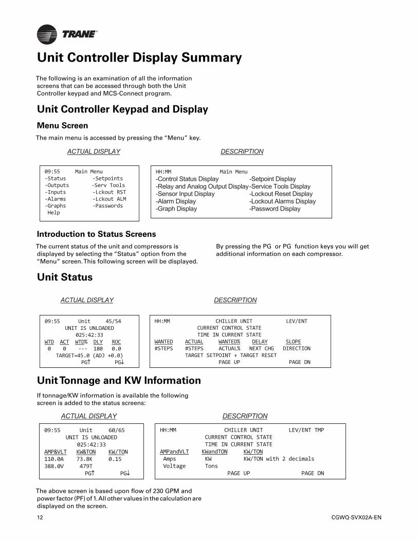
Unit Status
UnitTonnage and KW Information
If tonnage/KW information is available the followingscreen is added to the status screens:
The above screen is based upon flow of 230 GPM andpower factor (PF) of 1.All other values in the calculation aredisplayed on the screen.
ACTUAL DISPLAY DESCRIPTION
09:55 Main Menu -Status -Setpoints -Outputs -Serv Tools -Inputs -Lckout RST -Alarms -Lckout ALM -Graphs -Passwords Help
HH:MM Main Menu -Control Status Display -Setpoint Display-Relay and Analog Output Display-Service Tools Display-Sensor Input Display -Lockout Reset Display-Alarm Display -Lockout Alarms Display-Graph Display -Password Display
ACTUAL DISPLAY DESCRIPTION
09:55 Unit 45/54 UNIT IS UNLOADED
025:42:33 WTD ACT WTD% DLY ROC 0 0 --- 180 0.0
TARGET=45.0 (ADJ +0.0) PG↑↑ PG↓↓
HH:MM CHILLER UNIT LEV/ENT CURRENT CONTROL STATE TIME IN CURRENT STATE WANTED ACTUAL WANTED% DELAY SLOPE #STEPS #STEPS ACTUAL% NEXT CHG DIRECTION TARGET SETPOINT + TARGET RESET PAGE UP PAGE DN
ACTUAL DISPLAY DESCRIPTION
09:55 Unit 60/65 UNIT IS UNLOADED
025:42:33 AMP&VLT KW&TON KW/TON 110.0A 73.8K 0.15 388.0V 479T
PG↑↑ PG↓↓
HH:MM CHILLER UNIT LEV/ENT TMP CURRENT CONTROL STATE TIME IN CURRENT STATE AMPandVLT KWandTON KW/TON Amps KW KW/TON with 2 decimals Voltage Tons PAGE UP PAGE DN
12 CGWQ-SVX02A-EN
Unit Controller Display Summary
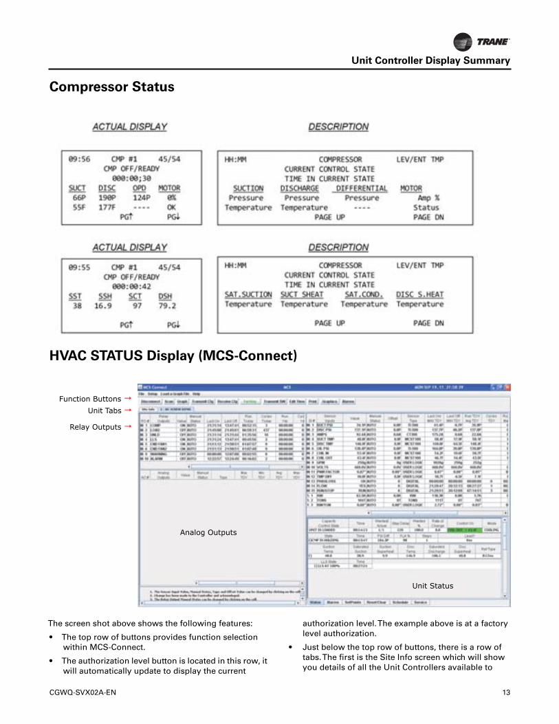
Compressor Status
HVAC STATUS Display (MCS-Connect)
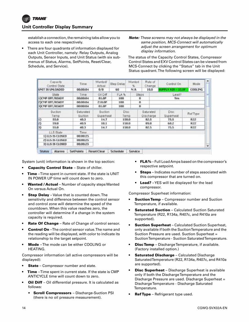
The screen shot above shows the following features:
• The top row of buttons provides function selectionwithin MCS-Connect.
• The authorization level button is located in this row, itwill automatically update to display the current
authorization level.The example above is at a factorylevel authorization.
• Just below the top row of buttons, there is a row oftabs.The first is the Site Info screen which will showyou details of all the Unit Controllers available to
Function Buttons Unit Tabs
Analog Outputs
Unit Status
Relay Outputs
CGWQ-SVX02A-EN 13
Unit Controller Display Summary
establish a connection, the remaining tabs allow you toaccess to each one respectively.
• There are four quadrants of information displayed foreach Unit Controller, namely: Relay Outputs, AnalogOutputs, Sensor Inputs, and Unit Status (with six sub-menus of Status, Alarms, SetPoints, Reset/Clear,Schedule, and Service).
Note: These screens may not always be displayed in thesame position, MCS-Connect will automaticallyadjust the screen arrangement for optimumdisplay information.
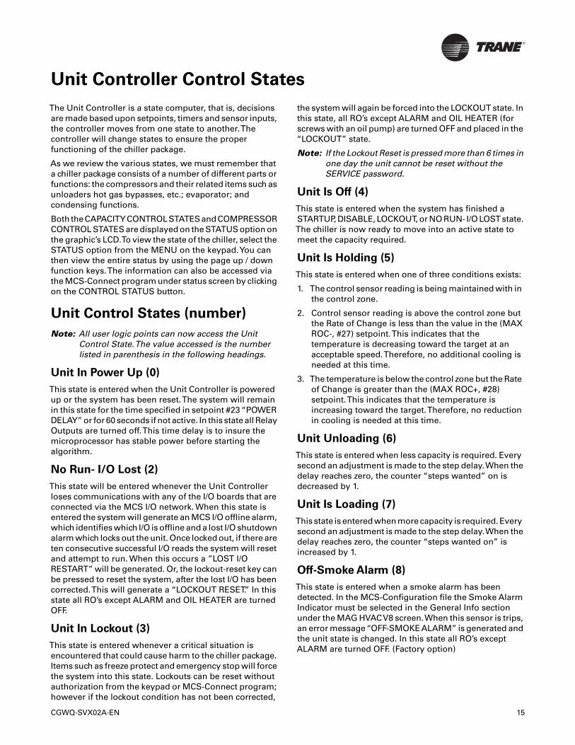
The status of the Capacity Control States, CompressorControl States and EXV Control States can be viewed fromMCS-Connect by clicking the “Status” tab in the UnitStatus quadrant.The following screen will be displayed:
System (unit) information is shown in the top section:
• Capacity Control State – State of chiller.
• Time –Time spent in current state. If the state is UNITIN POWER UP time will count down to zero.
• Wanted / Actual – Number of capacity steps WantedOn versus Actual On.
• Step Delay – Value that is counted down.Thesensitivity and difference between the control sensorand control zone will determine the speed of thecountdown. When this value reaches zero, thecontroller will determine if a change in the systemcapacity is required.
• Rate Of Change – Rate of Change of control sensor.
• Control On –The control sensor value.The name andthe reading will be displayed, with color to indicate itsrelationship to the target setpoint.
• Mode –The mode can be either COOLING orHEATING.
Compressor information (all active compressors will bedisplayed):
• State – Compressor number and state.
• Time –Time spent in current state. If the state is CMPANTICYCLE time will count down to zero.
• Oil Diff – Oil differential pressure. It is calculated asfollows:
• Scroll Compressors – Discharge-Suction PSI(there is no oil pressure measurement).
• FLA% – Full LoadAmps based on the compressor’srespective setpoint.
• Steps – Indicates number of steps associated withthis compressor that are turned on.
• Lead? –YES will be displayed for the leadcompressor.
Compressor Superheat information:
• SuctionTemp – Compressor number and SuctionTemperature, if available.
• Saturated Suction – Calculated Suction SaturatedTemperature (R22, R134a, R407c, and R410a aresupported).
• Suction Superheat – Calculated Suction Superheat,only available if both the SuctionTemperature and theSuction Pressure are used. Suction Superheat =SuctionTemperature - Suction SaturatedTemperature.
• DiscTemp – DischargeTemperature, if available.(Factory installed option.)
• Saturated Discharge – Calculated DischargeSaturatedTemperature (R22, R134a, R407c, and R410aare supported).
• Disc Superheat – Discharge Superheat is availableonly if both the DischargeTemperature and theDischarge Pressure are used. Discharge Superheat =DischargeTemperature - Discharge SaturatedTemperature.
• RefType – Refrigerant type used.
14 CGWQ-SVX02A-EN
Unit Controller Control States
The Unit Controller is a state computer, that is, decisionsare made based upon setpoints, timers and sensor inputs,the controller moves from one state to another.Thecontroller will change states to ensure the properfunctioning of the chiller package.
As we review the various states, we must remember thata chiller package consists of a number of different parts orfunctions: the compressors and their related items such asunloaders hot gas bypasses, etc.; evaporator; andcondensing functions.
Both the CAPACITY CONTROL STATES and COMPRESSORCONTROL STATES are displayed on the STATUS option onthe graphic’s LCD.To view the state of the chiller, select theSTATUS option from the MENU on the keypad.You canthen view the entire status by using the page up / downfunction keys.The information can also be accessed viathe MCS-Connect program under status screen by clickingon the CONTROL STATUS button.
Unit Control States (number)
Note: All user logic points can now access the UnitControl State.The value accessed is the numberlisted in parenthesis in the following headings.
Unit In Power Up (0)
This state is entered when the Unit Controller is poweredup or the system has been reset.The system will remainin this state for the time specified in setpoint #23 “POWERDELAY” or for 60 seconds if not active. In this state all RelayOutputs are turned off.This time delay is to insure themicroprocessor has stable power before starting thealgorithm.
No Run- I/O Lost (2)
This state will be entered whenever the Unit Controllerloses communications with any of the I/O boards that areconnected via the MCS I/O network. When this state isentered the system will generate an MCS I/O offline alarm,which identifies which I/O is offline and a lost I/O shutdownalarm which locks out the unit. Once locked out, if there areten consecutive successful I/O reads the system will resetand attempt to run. When this occurs a ”LOST I/ORESTART” will be generated. Or, the lockout-reset key canbe pressed to reset the system, after the lost I/O has beencorrected.This will generate a “LOCKOUT RESET.” In thisstate all RO’s except ALARM and OIL HEATER are turnedOFF.
Unit In Lockout (3)
This state is entered whenever a critical situation isencountered that could cause harm to the chiller package.Items such as freeze protect and emergency stop will forcethe system into this state. Lockouts can be reset withoutauthorization from the keypad or MCS-Connect program;however if the lockout condition has not been corrected,
the system will again be forced into the LOCKOUT state. Inthis state, all RO’s except ALARM and OIL HEATER (forscrews with an oil pump) are turned OFF and placed in the“LOCKOUT” state.
Note: If the Lockout Reset is pressed more than 6 times inone day the unit cannot be reset without theSERVICE password.
Unit Is Off (4)
This state is entered when the system has finished aSTARTUP, DISABLE, LOCKOUT, or NO RUN- I/O LOST state.The chiller is now ready to move into an active state tomeet the capacity required.
Unit Is Holding (5)
This state is entered when one of three conditions exists:
1. The control sensor reading is being maintained with inthe control zone.
2. Control sensor reading is above the control zone butthe Rate of Change is less than the value in the (MAXROC-, #27) setpoint.This indicates that thetemperature is decreasing toward the target at anacceptable speed.Therefore, no additional cooling isneeded at this time.
3. The temperature is below the control zone but the Rateof Change is greater than the (MAX ROC+, #28)setpoint.This indicates that the temperature isincreasing toward the target.Therefore, no reductionin cooling is needed at this time.
Unit Unloading (6)
This state is entered when less capacity is required. Everysecond an adjustment is made to the step delay.When thedelay reaches zero, the counter “steps wanted” on isdecreased by 1.
Unit Is Loading (7)
This state is entered when more capacity is required. Everysecond an adjustment is made to the step delay.When thedelay reaches zero, the counter “steps wanted on” isincreased by 1.
Off-Smoke Alarm (8)
This state is entered when a smoke alarm has beendetected. In the MCS-Configuration file the Smoke AlarmIndicator must be selected in the General Info sectionunder the MAG HVACV8 screen.When this sensor is trips,an error message“OFF-SMOKEALARM” is generated andthe unit state is changed. In this state all RO’s exceptALARM are turned OFF. (Factory option)
CGWQ-SVX02A-EN 15
Unit Controller Control States
Run/Stop Sw Off (9)
This state is entered when the run stop switch is off, in thestop position. When the chiller is in this state, theindividual compressor states if active are moved to theCMP IS OFF state through the normal states. One capacitySTEP will be moved per second. (CGWQ/CCAQ chillershave factory installed circuit enable switches. A fieldinstalled RUN/STOP switch can be added.)
Scheduled Off (10)
This state is entered when the schedule is calling for thepackage to be off. When the chiller is in this state, theindividual compressor states if active are moved to theCMP IS OFF state through the normal states. One capacitySTEP will be moved per second.
Off- No Flow (11)
This state is entered when the evaporator flow switch isoff. When the chiller is in this state, the individualcompressor states if active are moved to the CMP IS OFFstate through the normal states. One capacity STEP will bemoved per second. If the NO FLOW setpoint is active andset to Lockout the chiller will lockout on no flow.
Ambient Off (13)
This state is entered when the ambient temperature fallsbelow setpoint #24 “LOW AMB OFF” or is above setpoint#26 “HIGH AMB OFF”.The system will remain in this stateuntil the ambient temperature if low rises 5.0°F (2.5°C)above the “LOW AMB OFF” setpoint value or if high drops5.0°F (2.5°C) below the “HIGH AMB OFF” setpoint value.When the chiller is in this state, the individual compressorstates if active are moved to the CMP IS OFF state throughthe normal staging function. One capacity STEP will bemoved per second. (Factory option)
Unit Is Unloaded (15)
This state is entered when all of the systems availablecapacity steps are off.The package is providing no coolingcapacity, as none is required.The system is ready to reactto cooling needs.
Unit Is Loaded (16)
This state is entered when all of the system’s availablecapacity steps are on and the package is providing themaximum amount of cooling capacity.
OffTmp-Ice Made (17)
This state is entered when target temperature has beensatisfied.
Unit Off Unlding (21)
This state is entered when the unit has been disabled. Itwill force a quick unload of the system.
Unit Dmd Unlding (22)
This state is only entered when the demand limiting inputhas been selected.The demand limit sensor must beselected in the General Information section under theMAG HVACV8 screen and its type must be“485 Dmd Step”.This input will indicate the maximum number of steps thatthe unit can run. If this value is less than the number ofsteps that are currently on, the unit will unload to meet thisvalue. (Factory option)
Compressor Control States
The action of the compressor control states may result inan increase or decrease in capacity.The Unit ControlStates may affect or change the Compressor ControlStates or supersede them altogether.
Lost I/O Locked (0)
This state is entered when the Capacity Control State is NORUN- I/O LOST. Resetting the lockout will move thecompressor to the CMP OFF/READY state.
Cmp Locked Out (1)
This state is entered when the Capacity Control State is inUNIT IN LOCKOUT or a safety trip has occurred for thiscompressor (Examples of safety setpoints include #77“LOW SUCTION” and #81 “HI DISCH PSI”). Lockouts canbe reset without authorization from the keypad or MCS-Connect program, however if the condition causing thelockout has not been corrected, the compressor will againbe forced into the LOCKOUT State.
Switched Off (2)
This state is entered when the compressor is off due to thecircuit enable switch being off. In this state the compressorand all related points, including the liquid line solenoid areoff.The compressor will not leave this state unless theenable switch is turned on. If the enable switch is turnedon, the compressor state will be changed to the CMP OFF/READY state.
Cmp Anticyce (4)
This state is entered when the UNLD and PMPDWN statehas been completed.The compressor will stay in this statewith all compressor points off for the period of timecontained in setpoint #59 “ACYC OFF-> ON” or setpoint#63 “ACYC ON -> ON”, whichever is longer.Thecompressor will then move to the OFF state. NOTE: “ACYCON -> ON” can be used to set the maximum number ofcompressor starts per hour.
Cmp Off/Ready (5)
This state is entered when no capacity is required from thiscompressor, or the last state was CMP ANTICYCE, LOST I/O LOCKED, or SWITCHED OFF. In this state the compressoris ready to provide capacity if needed.The compressor willremain in this state for a minimum of 60 seconds.
16 CGWQ-SVX02A-EN
Unit Controller Control States
Cmp Unloaded (8)
For fixed step compressors, this state occurs when thecompressor is on and any associated Hot Gas Bypass is on.In this state the compressor is supplying its minimumcooling capacity.
Cmp Is Running (14)
For fixed capacity compressors only, this state occurswhen the compressor is fully loaded. In this state, thecompressor is providing the maximum amount of coolingcapacity.
SafetyTripped (20)
This state is entered when a safety trip occurs but a lockoutis not generated.An alarm is generated but the system willautomatically restart after the delay specified in thecorresponding setpoint. If a second trip occurs within thetime specified in the setpoint, the compressor will beplaced in the CMP LOCKED OUT state.
CGWQ-SVX02A-EN 17
18 CGWQ-SVX02A-EN
Setpoint Definitions
SetpointTypes
There are three different types of setpoints.The UnitController software determines if a setpoint contains atarget value or is a safety. If it is a safety then its typedetermines what action the system will take when thesafety occurs (either locking out the unit or generating analarm only).
Setpoint
This type of setpoint contains a target or providesinformation for some action.The time element in this typecan be used for an additional counter if specified.This timeis displayed and can be changed through MCS-Connect,MCS-Config or from the keypad display.
Lockout
This type of setpoint contains a safety value and the timethat the safety must be violated before the safety will trip.Once a safety has tripped the system will take theappropriate action, shutting down the entire package or anindividual compressor depending on the purpose of thesafety.The system will then wait the Safety DownTimecontained in that setpoint before trying to return thenormal. If successful, the system will continue to operate.If a second trip occurs on the same setpoint with in theLock Out DelayTime that is contained in that setpoint thesystem will move to a LOCKOUT state. If the lockout delaytime is set to zero the lockout will occur on the first trip.This requires manual intervention to reset the system.With each safety trip, the system will generate an alarm;refer to page 25. Unit Controller Alarms and Safeties.
The Safety DownTime and the Lock Out DelayTime areunique for each setpoint.They cannot be viewed oradjusted in a live unit; only through MCS-Config.
Alarm
This type of setpoint has two uses:
1. When it is used as a safety, it will be similar to theLOCKOUT setpoint except it will never cause a lock out.The system will continue to try returning to normaloperation after waiting the safety down time. AnALARM setpoint type will never require manualintervention to reset the system.
When the setpoint is being used as a second timer it willbe available to change in a live unit. If the type is notchanged toALARM then the time field cannot be viewed orchanged from a live unit.
CGWQ-SVX02A-EN 19
Authorization Function
The authorization code is a special four-character code thatenables access to the Unit Controller.
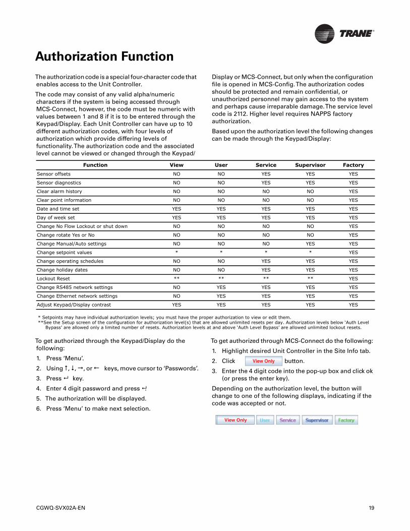
The code may consist of any valid alpha/numericcharacters if the system is being accessed throughMCS-Connect, however, the code must be numeric withvalues between 1 and 8 if it is to be entered through theKeypad/Display. Each Unit Controller can have up to 10different authorization codes, with four levels ofauthorization which provide differing levels offunctionality.The authorization code and the associatedlevel cannot be viewed or changed through the Keypad/
Display or MCS-Connect, but only when the configurationfile is opened in MCS-Config.The authorization codesshould be protected and remain confidential, orunauthorized personnel may gain access to the systemand perhaps cause irreparable damage.The service levelcode is 2112. Higher level requires NAPPS factoryauthorization.
Based upon the authorization level the following changescan be made through the Keypad/Display:
* Setpoints may have individual authorization levels; you must have the proper authorization to view or edit them.**See the Setup screen of the configuration for authorization level(s) that are allowed unlimited resets per day. Authorization levels below ‘Auth Level
Bypass’ are allowed only a limited number of resets. Authorization levels at and above ‘Auth Level Bypass’ are allowed unlimited lockout resets.
To get authorized through the Keypad/Display do thefollowing:
1. Press ‘Menu’.
2. Using , ,, orkeys, move cursor to ‘Passwords’.
3. Press key.
4. Enter 4 digit password and press .
5. The authorization will be displayed.
6. Press ‘Menu’ to make next selection.
To get authorized through MCS-Connect do the following:
1. Highlight desired Unit Controller in the Site Info tab.
2. Click button.
3. Enter the 4 digit code into the pop-up box and click ok(or press the enter key).
Depending on the authorization level, the button willchange to one of the following displays, indicating if thecode was accepted or not.
Function View User Service Supervisor Factory
Sensor offsets NO NO YES YES YES
Sensor diagnostics NO NO YES YES YES
Clear alarm history NO NO NO NO YES
Clear point information NO NO NO NO YES
Date and time set YES YES YES YES YES
Day of week set YES YES YES YES YES
Change No Flow Lockout or shut down NO NO NO NO YES
Change rotate Yes or No NO NO NO NO YES
Change Manual/Auto settings NO NO NO YES YES
Change setpoint values * * * * YES
Change operating schedules NO NO YES YES YES
Change holiday dates NO NO YES YES YES
Lockout Reset ** ** ** ** YES
Change RS485 network settings NO YES YES YES YES
Change Ethernet network settings NO YES YES YES YES
Adjust Keypad/Display contrast YES YES YES YES YES
View Only
View Only
Standard Control Options
The following options are specified in MCS-Config whenbuilding the configuration.These options are used tocustomize the system to meet the individual controlrequirements.
General Options
• Control method can be based upon the control zone ora voltage input indicating the number of stages to beon.
• The control temperature sensor can be either thereturning or leaving sensor.
• Chilled water reset from the Building ManagementSystem (BMS).
• Condenser control maintaining sufficient dischargesuperheat for good oil separation.
• Evaporator pump control.
• Anti-cycle timers (OFF to ON and ON to ON).
• Maximum of 20 circuits per Unit Controller, withselectable compressor rotation.
• Warning RO (turned on for low suction unload, highdischarge unload, etc.).
• Alarm RO (turned on whenever an alarm is generated).
• Optional auto rotation for compressors.
• Low and/or high ambient temperature shut down.
Chilled Water Reset
ChilledWater Reset (CWR) is a 0 to 5 volts dc sensor input(DisplayType isTRGTRST) to the MCS microprocessor.The CWR follows the following rules using setpoint #21,MAXTRG RESET: (Factory option)
1. If the input is 2.5 volts dc the CWR is zero.
2. At 0 vdc the CWR is a negative value equal to thesetpoint value.
3. At 5 vdc the CWR is a positive value equal to the valuein the setpoint.
4. For values in between 0 – 2.5 and 2.5 – 5.0 the CWR isa plus or minus value which is proportional to thesensor input voltage.
On/Off Switches
The following digital inputs can affect the entire packageor individual circuits:
• Flow Switch – If OFF the system has no flow.Thesystem will Lock Out (if setpoint #105 is active), or shutdown (if setpoint #105 is inactive). (Will only lock out ifchiller has control of the Chilled water pump starter.This is a factory option for process chillers.)
• Run/Stop – If OFF the system will not run. If the systemis running, the system turns all compressors off innormal steps (If a RUN/STOP and a Network RUN/STOP are both available they operate in series).(CGWQ/CCAQ chillers have factory installed circuitenable switches.A field installed RUN/STOP switch canbe added.)
• Network Run/Stop – If OFF the system will not run.This input is provided by another system on thenetwork. It functions in the same matter as the Run/Stop switch.
Note: CGWQ/CCAQ chillers shipped with BMS option areshipped with this indicator set to MANUAL ON.Enter password 2112 from keypad then selectNET RN/STOP and set to AUTO to allow networkcontrol.
Chilled Water Pump Control
The system will support a chilled water pump plus abackup with rotation.These must be set up in theMCS-Config program. (This is a factory option)
Setpoint #105 and Setpoint #106 are used with this controllogic.
If setpoint #105, PUMP FAILURE, is active and flow is lostfor the period of time contained in the value and only onepump is present the system will move to a LOCK OUTstate. If the system has two pumps and flow is lost thebackup pump will start and the lead pump will be lockedout. A lock out reset will be required to restart the systemor to reactive a locked out pump.
If this setpoint is inactive and the flow is lost, the systemwill move to the OFF- NO EVAP FLOW state. When flow isreturned the system will automatically restart, no reset isrequired.
Setpoint #106, LEAD PUMP, indicates whether the rotationoption is active or which pump is the lead pump.
If the setpoint #106’s value is zero, then rotation of thepumps will occur whenever the lead pump is turned off. Ifno rotation has occurred during the current day, a forcedrotation at midnight will occur.This forces at least onerotation per day.
If the setpoint #106’s value is non-zero, then rotation of thepumps is inactive and the value will specify the lead pump.This setpoint can be changed in a live unit and theappropriate action will be taken.
20 CGWQ-SVX02A-EN
Standard Control Options
Low and High Ambient Shutdown
The system supports both a low and a high ambient shutdown.This option requires an ambient temperaturesensor and both LOW AMB OFF setpoint (#24) and HIGHAMB OFF setpoint (#26).The AMBIENT OFF state isentered when the ambient temperature falls below theLOW AMB OFF setpoint (#24) or is above the HIGH AMBOFF setpoint (#26).The system will remain in this stateuntil the ambient temperature rises 5.0°F (or 2.5°C) abovethe LOW AMB OFF setpoint value or drops 5.0°F (or 2.5°C)below the HIGH AMB OFF setpoint value.When the chilleris in this state, the individual compressor states if activeare moved to the CMP IS OFF state through the normalstaging function. One capacity STEP will be moved persecond. (Factory option.)
Compressor Auto Rotation
The auto rotation option is selected by setting the value insetpoint #103, LEAD COMP to zero. If this value is not zero,it will contain the number of the lead compressor and autorotation is disabled. Note this setpoint can be manuallychanged to force a different compressor as the leadcompressor or to enable auto rotation. (Setting this to 0will start the compressor that’s been off the longest to startnext and the compressor that’s been running longest tostop next.)
When this option is enabled, the system will rotate thecompressors based upon the value in setpoint # 104, CMPROTATION.
If setpoint # 104 value is zero, rotation will occur with everycomplete capacity cycle and the next compressor will beselected as the lead compressor. (As described above.)
Else, the value is the number of days between rotations.Atmidnight the system will check if it is time to rotatecompressors. If yes, the system will check the run hours oneach compressor and select the one with the least amountof run hours to be the lead compressor.
Compressor Anti-Cycle Logic
When a compressor is to be turned off, the system willmake a calculation to determine the amount of time thatthe compressor shall be in an anti-cycle state.Thiscalculation is based upon how long the compressor hasbeen on and setpoints #59 (ACYC OFF->ON) and #63 (ACYCON->ON).
If the value of setpoint #63 minus the amount of time thatthe compressor has been on is greater than the value insetpoint #59, the compressor will remain in the anti-cyclestate for the period of time specified in setpoint #63. Elsethe anti-cycle time will be set to the value in setpoint #59.
For example:
A compressor has been running for 180 seconds
#59 (ANTI-CYC OFF) = 300 seconds#63 (ANTI-CYC ON) = 600 seconds
600 – 180 = 420 this is greater than setpoint #59; therefore,the anti-cycle timer will be set to 600 seconds, the value ofsetpoint #63.
If the compressor had been running for 12 minutes (720seconds)
600 – 720 = -120 this is less than setpoint #59; therefore, theanti-cycle timer will be set to 300 seconds, the value ofsetpoint #59.
If the controller losses power, the length of time that thesystem was down will be taken into consideration whendetermining whether the compressor should be in an anti-cycle state and for how long.
Alarm Relay Outputs
Alarm Relay Output will be turned on whenever thesystem generates an alarm type of message.Thisindicates that a safety or lockout condition has occurred.
Operating Schedules
Two operating schedules per each day of the week and 8holidays are supported. Each schedule contains a start andend time, if the time and day of the system is within theselimits the schedule is true and the system will be allowedto run. If not, the system will be off due to schedule.
Compressor Lead and Rotation
Refer to Setpoints #103 and #104.
CGWQ-SVX02A-EN 21
Condenser Control Logic
Many condenser types are supported by the UnitController including individual condensers per circuit,shared condensers between multiple circuits, andcommon condensers for all circuits.The type of condenserplus the number of relay outputs needed are specified inMCS-Config.
CGWQ/CCAQ chillers are factory programmed as follows:
1 circuit air-cooled chillers have up to 3 dry contactrelays for controlling fans.The controller has one 0 to10VDC analog output to control a VFD or fan damperactuator.
2 circuit air-cooled chillers have up to 8 dry contactrelays (4 per circuit) for controlling fans plus 2-0 to 10VDCanalog outputs.
1 circuit water-cooled chillers have one dry contactrelay to start a condenser pump.These chillers also haveone 0 to 10VDC analog output to control a head pressurecontrol valve.
2 circuit water-cooled chillers have one dry contactrelay to start a condenser pump.These chillers have two 0to 10 VDC analog outputs (one for each circuit) to controlhead pressure control valves.
RO Step Condenser Cut In – Out
Logic
The Cut In and Cut Out Logic setpoints are as follows:
Setpoint #45 “CND STG1 ON”- Condenser stage 1 Cut In(ON).
Setpoint #46“CND STG1 OFF”- Condenser stage 1 Cut Out(OFF).
Setpoint #47 “CND DIFF ON“- Cut In differential foradditional condenser stages for (ON).
Setpoint #48 “CND DIFF OFF”- Cut Out differential foradditional condenser stages (OFF).
Setpoint #49 “CND MIN RUN”- Minimum run time for acondenser stage
Condenser relay outputs will be turned on based upon thevalue in setpoint #45 “CND STG1 ON”. When dischargepressure reaches this value, the first condenser relayoutput is turned on. If additional condenser outputs exist,they will be turned on when the pressure exceeds the cutin value plus the value contained in setpoint #47 “CNDDIFF ON“. When discharge pressure falls, the condenseroutputs will be turned off based upon the setpoint #46“CND STG1 OFF” plus the value contained in setpoint #48“CND DIFF OFF”.The first step will be turned off whendischarge pressure falls below setpoint #46 “CND STG1OFF”.
Example:
Setpoint #45 “CND STG1 ON” = 320 psi
Setpoint #46 “CND STG1 OFF”= 250 psi
Setpoint #47 “CND DIFF ON” = 50 psi
Setpoint #48 “CND DIFF OFF”= 20 psi
Setpoint #51 “CND VFD START = 100%
COND FAN 1 ON at 320 psi (Discharge)
COND FAN 1 OFF at 250 psi
COND FAN 2 ON at 370 psi (320 + 50)
COND FAN 2 OFF at 270 psi (250 + 20)
Note: Setting theVFD START% to 30% would start the fanand/or damper at about 259 psi to allow dampertime to open prior to needlessly starting anotherfan.
RO Step Condenser with
Variable Speed Fan or Damper
The setpoints for variable speed fan control are as follows:
Setpoint #54 “VFD MIN%”- Minimum variable speedallowed.
Setpoint #55 “VFD MAX%“- Maximum variable speedallowed.
The purpose of the variable speed fan is to reduce thecycling of the fans by adjusting the speed of the variablefan point.This control works in conjunction with the Cut Inand Cut Out logic of each circuit.When a fan is turned on,the speed of the variable point for that compressor is setto maximum allowed percentage. As the dischargepressure falls, the fan speed is adjusted proportionally.When the minimum is reached the fan will turn off.
Condenser Related Setpoints
Refer to pages 47 & 48 for the following condenser relatedsetpoints:
#45”CND FAN ON” . . . . . . . . . . . . . . . . . . . . . (Air Cooled)
#46”CND FAN OFF” . . . . . . . . . . . . . . . . . . . . (Air Cooled)
#47”CND DIFF ON” . . . . . . . . . . . . . . . . . . . . . (Air Cooled)
#48”CND DIFF OFF” . . . . . . . . . . . . . . . . . . . . (Air Cooled)
#48”CND DELAY” . . . . . . . . . . . . . . . . . . . . (Water Cooled)
#49”CND MIN RUN” . . . . . . . . . . . . . . . . . . . . (Air Cooled)
#49”CND VLV START” . . . . . . . . . . . . . . . . (Water Cooled)
#50”CND VLVTARG” . . . . . . . . . . . . . . . . . . (Water Cooled)
#51”CND VLV DIV” . . . . . . . . . . . . . . . . . . (Water Cooled)
#51”CND VFD START” . . . . . . . . . . . . . . . . . . (Air Cooled)
#52”CND VLV MIN” . . . . . . . . . . . . . . . . . . . (Water Cooled)
#53”CND VLV ROC-” . . . . . . . . . . . . . . . . . . (Water Cooled)
#54”VFD MIN%” . . . . . . . . . . . . . . . . . . . . . . . (Air Cooled)
#55”VFD MAX%” . . . . . . . . . . . . . . . . . . . . . . (Air Cooled)
#55”CND MIN ADJ” . . . . . . . . . . . . . . . . . . (Water Cooled)
22 CGWQ-SVX02A-EN
Condenser Control Logic
Fan or Damper Analog Output (AO)Control (same for all types of aircondenser control)
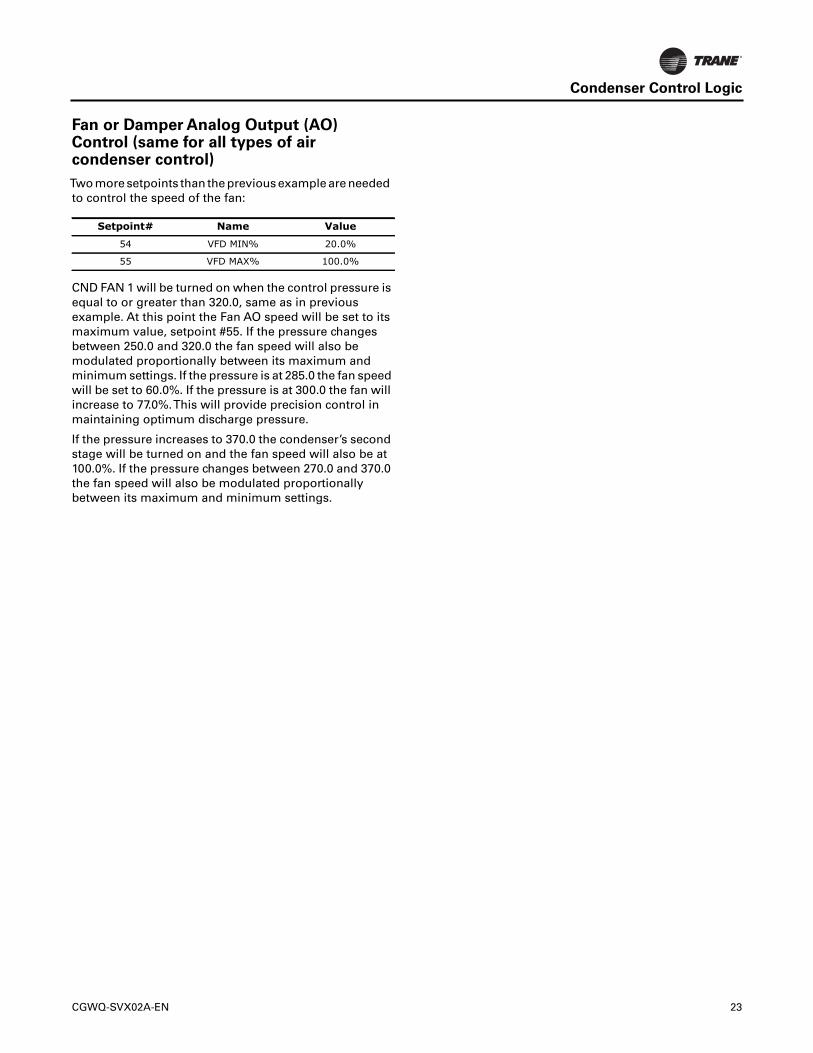
Two more setpoints than the previous example are neededto control the speed of the fan:
CND FAN 1 will be turned on when the control pressure isequal to or greater than 320.0, same as in previousexample. At this point the Fan AO speed will be set to itsmaximum value, setpoint #55. If the pressure changesbetween 250.0 and 320.0 the fan speed will also bemodulated proportionally between its maximum andminimum settings. If the pressure is at 285.0 the fan speedwill be set to 60.0%. If the pressure is at 300.0 the fan willincrease to 77.0%.This will provide precision control inmaintaining optimum discharge pressure.
If the pressure increases to 370.0 the condenser’s secondstage will be turned on and the fan speed will also be at100.0%. If the pressure changes between 270.0 and 370.0the fan speed will also be modulated proportionallybetween its maximum and minimum settings.
Setpoint# Name Value
54 VFD MIN% 20.0%
55 VFD MAX% 100.0%
CGWQ-SVX02A-EN 23
Unit Controller Alarms and Safeties
There are three types of alarms that are generated by theUnit Controller control logic:
• Information only alarms
• Unit Controller system alarms
• Chiller setpoint safety alarms
All alarms have the same format.The alarm is identifiedand is date/time stamped. Alarms can be viewed from theUnit Controller keypad by selecting the ‘Alarms’ from themain menu, or through MCS-Connect.
Information Only Alarms
System Generated Alarms
The following alarms are generated to provideinformation; they will not cause a change in the controlalgorithm such as a lock out condition or a relay outputbeing forced off.
• POWER FAILED – Generated when power to the UnitController was lost.
• POWER RETURNED – Generated when power to theUnit Controller returned.
• HW DATE INVALID –The date contained/read fromthe hardware real time clock chip is not valid. Checkbattery voltage, it should be > 2.0 vdc.
• HWTIME INVALID –The time contained/read fromthe hardware real time clock chip is not valid. Checkbattery voltage, it should be > 2.0 vdc.
• SW DATE INVALID –The date contained/read fromthe software clock is not valid.
• SWTIME INVALID –The time contained/read fromthe software clock is not valid.
• RAM INTEGRITY – the data contained in the battery-backed up RAM memory may be corrupted.This doesnot stop the Unit Controller from running. It means thehistorical data may be incorrect (run times, cycles, min/max values, and trend/graph data).
• WATCHDOG RESET –The Unit Controller has resetitself because of improper operator of the UnitController board. Please consult the manufacturer ifthis alarm has occurred.
• LOST A/D CONVTR –The Unit Controllermicroprocessor has lost communications to theAnalog to Digital converter chip (chip that convertssensor voltages to a digital number). Check for ashorted sensor that may cause.
• LOST DISPLAY – Generated when communication tothe Keypad/Display is lost.
• CF INIT ERROR –The Compact Flash card that wasinstalled cannot be initialized and therefore cannot beused. Replace the Compact Flash card with one thatworks.
• BATTERY FAILED – Generated when Unit Controlleris not getting power from the Battery.
User Initiated Alarms
The following alarms indicate that an individual tookaction: (Most require proper authorization)
• LOCKOUT RESET – Generated when a user resets acompressor other unit from a locked condition.
• COMPUTER RESET – Generated when the manualreset button on the Unit Controller is pressed.
• ALARMS CLEARED – Generated when a user clearsthe alarm history.
• STPT CHANGED – Generated when a user makes achange to a setpoint; the number of the setpoint willalso be displayed with the alarm.
• ROTO (Selected Condition) – Generated when auser manually changes the condition of a Relay Output(either AUTO, MANON, or MANOFF).
• AOTO (Selected Condition) – Generated when auser changes the condition of anAnalog Output (eitherAUTO or MANUAL. If MANUAL, then a dialog box willappear to input the number value).
• SITO (Selected Condition) – Generated when a userchanges the condition of a Sensor Input (If a digitalinput, then either AUTO, MANON, or MANOFF. If ananalog input, then either AUTO or MANUAL. IfMANUAL, then a dialog box will appear to input thenumber value).
• POINT INFO CLEAR – Generated when a user clearsall point information (run times, cycles, min/maxvalues, etc).
• CLOCK SET – Generated when a user makes a changeto the Unit Controller real time clock.
• CFG DOWNLOADED – Generated when a useruploads a new configuration file into the UnitController.
• ETHERNET CHANGE – Generated when a usermakes a change to the Ethernet settings through theKeypad/Display.
• RS485 CHANGED – Generated when a user makeschanges to the RS485 address through the Keypad/Display.
• CF CARD INSERTED – Generated when a user insertsa Compact Flash memory card into the Unit Controller.
• CF CARD REMOVED – Generated when a userremoves a Compact Flash memory card from the UnitController.
Automatic Alarms
The following alarms indicate an action that the UnitController made automatically:
24 CGWQ-SVX02A-EN
Unit Controller Alarms and Safeties
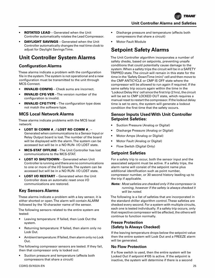
• ROTATED LEAD – Generated when the UnitController automatically rotates the Lead Compressor.
• DAYLIGHT SAVINGS – Generated when the UnitController automatically changes the real time clock toadjust for Daylight SavingsTime.
Unit Controller System Alarms
Configuration Alarms
These alarms indicate a problem with the configurationfile in the system.The system is not operational and a newconfiguration must be transmitted to the unit throughMCS-Connect.
• INVALID CONFIG – Check sums are incorrect.
• INVALID CFG VER –The version number of theconfiguration is invalid.
• INVALID CFGTYPE –The configuration type doesnot match the software type.
MCS Local Network Alarms
These alarms indicate problems with the MCS localnetwork:
• LOST SI COMM #_ / LOST RO COMM #_ –Generated when communications to a Sensor Input orRelay Output board is lost.The number of the boardwill be displayed with the alarm.The system can beaccessed but will be in a NO RUN- I/O LOST state.
• MCS-STAT OFFLINE –The Unit Controller has lostcommunications to the MCS-STAT.
• LOST IO SHUTDOWN – Generated when UnitController is running and there are no communicationsto one or more of the I/O boards.The system can beaccessed but will be in a NO RUN- I/O LOST state.
• LOST I/O RESTART – Generated when the UnitController does an automatic reset once I/Ocommunications are restored.
Key Sensors Alarms
These alarms indicate a problem with a key sensor, it iseither shorted or open.The alarm will contain ALARMfollowed by the 10-character name of the sensor.
The following sensors related to the entire system aretested:
• Leaving temperature: If failed, then Lock Out thesystem.
• Returning temperature: If failed, then alarm only noLock Out.
• Ambient temperature: If failed, then alarm only no LockOut.
The following compressor sensors are tested. If they fail,then that compressor only is locked out:
• Suction pressure and temperature (affects bothcompressors that share a circuit)
• Discharge pressure and temperature (affects bothcompressors that share a circuit)
• Motor Fault Module
Setpoint Safety Alarms
The Unit Controller algorithm incorporates a number ofsafety checks, based on setpoints, preventing unsafeconditions that could potentially cause damage to thesystem.When a safety trips the circuit will be in a SAFETYTRIPPED state.The circuit will remain in this state for thetime in the ‘Safety DownTime (min)’ cell and then move tothe CMP ANTICYCLE or CMP IS OFF state where thecompressor will be allowed to run again if required. If thesame safety trip occurs again within the time in the‘Lockout Delay Hrs’ cell since the first trip (2 hrs), the circuitwill be set to CMP LOCKED OUT state, which requires amanual reset to restart the compressor. If the lockout delaytime is set to zero, the system will generate a lockoutcondition the first time that the safety occurs.
Sensor Inputs Used With Unit ControllerSetpoint Safeties:
• Suction Pressure (Analog or Digital)
• Discharge Pressure (Analog or Digital)
• Motor Amps (Analog or Digital)
• Motor Fault (Analog or Digital)
• Flow Switch (Digital Only)
Setpoint Safeties
For a safety trip to occur, both the sensor input and theassociated setpoint must be active. If a safety trips, thealarm name will consist of the setpoint name plusadditional identification such as point number,compressor number, or 30 second history leading up tothe trip if applicable.
Note: Most safeties are checked only if the compressor isrunning, however if the safety is always checked itwill be noted.
The following is a list of safeties that are incorporated inthe standard chiller algorithm control.These safeties arechecked every second. For a system with multiple circuits,each one is tested individually. If a safety trip occurs, onlythat respective compressor will be affected, the others willcontinue to function normally.
Freeze Protection
(Safety Is Always Checked)
If the leaving temperature drops below the setpoint valuethen the entire system will Lock Out and a FREEZE alarmwill be generated.
No Flow Protection
If a flow switch is used, then the entire system will beLocked Out if setpoint #105 is active. If the setpoint isinactive, the system will determine if there is a second
CGWQ-SVX02A-EN 25
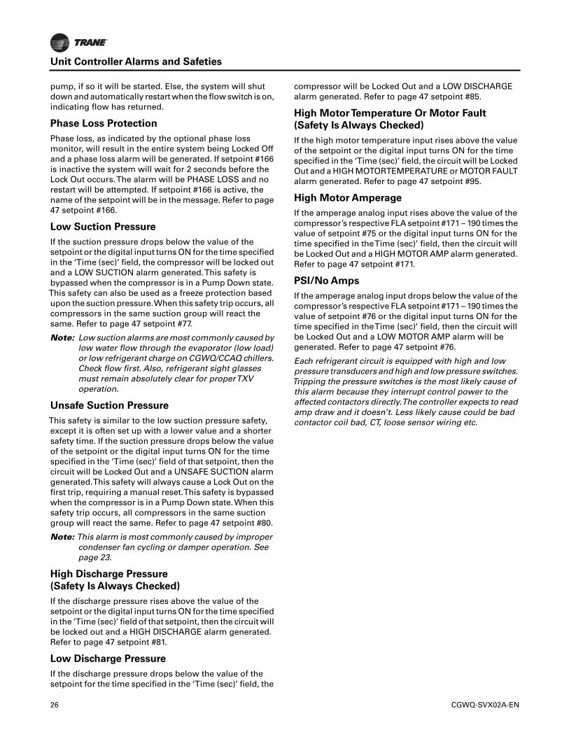
Unit Controller Alarms and Safeties
pump, if so it will be started. Else, the system will shutdown and automatically restart when the flow switch is on,indicating flow has returned.
Phase Loss Protection
Phase loss, as indicated by the optional phase lossmonitor, will result in the entire system being Locked Offand a phase loss alarm will be generated. If setpoint #166is inactive the system will wait for 2 seconds before theLock Out occurs.The alarm will be PHASE LOSS and norestart will be attempted. If setpoint #166 is active, thename of the setpoint will be in the message. Refer to page47 setpoint #166.
Low Suction Pressure
If the suction pressure drops below the value of thesetpoint or the digital input turns ON for the time specifiedin the ‘Time (sec)’ field, the compressor will be locked outand a LOW SUCTION alarm generated.This safety isbypassed when the compressor is in a Pump Down state.This safety can also be used as a freeze protection basedupon the suction pressure.When this safety trip occurs, allcompressors in the same suction group will react thesame. Refer to page 47 setpoint #77.
Note: Low suction alarms are most commonly caused bylow water flow through the evaporator (low load)or low refrigerant charge on CGWQ/CCAQ chillers.Check flow first. Also, refrigerant sight glassesmust remain absolutely clear for properTXVoperation.
Unsafe Suction Pressure
This safety is similar to the low suction pressure safety,except it is often set up with a lower value and a shortersafety time. If the suction pressure drops below the valueof the setpoint or the digital input turns ON for the timespecified in the ‘Time (sec)’ field of that setpoint, then thecircuit will be Locked Out and a UNSAFE SUCTION alarmgenerated.This safety will always cause a Lock Out on thefirst trip, requiring a manual reset.This safety is bypassedwhen the compressor is in a Pump Down state.When thissafety trip occurs, all compressors in the same suctiongroup will react the same. Refer to page 47 setpoint #80.
Note: This alarm is most commonly caused by impropercondenser fan cycling or damper operation. Seepage 23.
High Discharge Pressure
(Safety Is Always Checked)
If the discharge pressure rises above the value of thesetpoint or the digital input turns ON for the time specifiedin the ‘Time (sec)’ field of that setpoint, then the circuit willbe locked out and a HIGH DISCHARGE alarm generated.Refer to page 47 setpoint #81.
Low Discharge Pressure
If the discharge pressure drops below the value of thesetpoint for the time specified in the ‘Time (sec)’ field, the
compressor will be Locked Out and a LOW DISCHARGEalarm generated. Refer to page 47 setpoint #85.
High MotorTemperature Or Motor Fault
(Safety Is Always Checked)
If the high motor temperature input rises above the valueof the setpoint or the digital input turns ON for the timespecified in the ‘Time (sec)’ field, the circuit will be LockedOut and a HIGH MOTORTEMPERATURE or MOTOR FAULTalarm generated. Refer to page 47 setpoint #95.
High Motor Amperage
If the amperage analog input rises above the value of thecompressor’s respective FLA setpoint #171 – 190 times thevalue of setpoint #75 or the digital input turns ON for thetime specified in theTime (sec)’ field, then the circuit willbe Locked Out and a HIGH MOTOR AMP alarm generated.Refer to page 47 setpoint #171.
PSI/No Amps
If the amperage analog input drops below the value of thecompressor’s respective FLA setpoint #171 – 190 times thevalue of setpoint #76 or the digital input turns ON for thetime specified in theTime (sec)’ field, then the circuit willbe Locked Out and a LOW MOTOR AMP alarm will begenerated. Refer to page 47 setpoint #76.
Each refrigerant circuit is equipped with high and lowpressure transducers and high and low pressure switches.Tripping the pressure switches is the most likely cause ofthis alarm because they interrupt control power to theaffected contactors directly.The controller expects to readamp draw and it doesn’t. Less likely cause could be badcontactor coil bad, CT, loose sensor wiring etc.
26 CGWQ-SVX02A-EN
CGWQ-SVX02A-EN 27
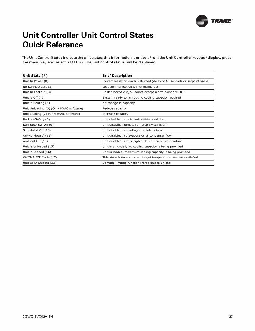
Unit Controller Unit Control States
Quick Reference
The Unit Control States indicate the unit status; this information is critical. From the Unit Controller keypad / display, pressthe menu key and select STATUS>.The unit control status will be displayed.
Unit State (#) Brief Description
Unit In Power (0) System Reset or Power Returned (delay of 60 seconds or setpoint value)
No Run-I/O Lost (2) Lost communication Chiller locked out
Unit In Lockout (3) Chiller locked out, all points except alarm point are OFF
Unit is Off (4) System ready to run but no cooling capacity required
Unit is Holding (5) No change in capacity
Unit Unloading (6) (Only HVAC software) Reduce capacity
Unit Loading (7) (Only HVAC software) Increase capacity
No Run-Safety (8) Unit disabled: due to unit safety condition
Run/Stop SW Off (9) Unit disabled: remote run/stop switch is off
Scheduled Off (10) Unit disabled: operating schedule is false
Off-No Flow(s) (11) Unit disabled: no evaporator or condenser flow
Ambient Off (13) Unit disabled: either high or low ambient temperature
Unit is Unloaded (15) Unit is unloaded, No cooling capacity is being provided
Unit is Loaded (16) Unit is loaded, maximum cooling capacity is being provided
Off TMP-ICE Made (17) This state is entered when target temperature has been satisfied
Unit DMD Unlding (22) Demand limiting function: force unit to unload
28 CGWQ-SVX02A-EN
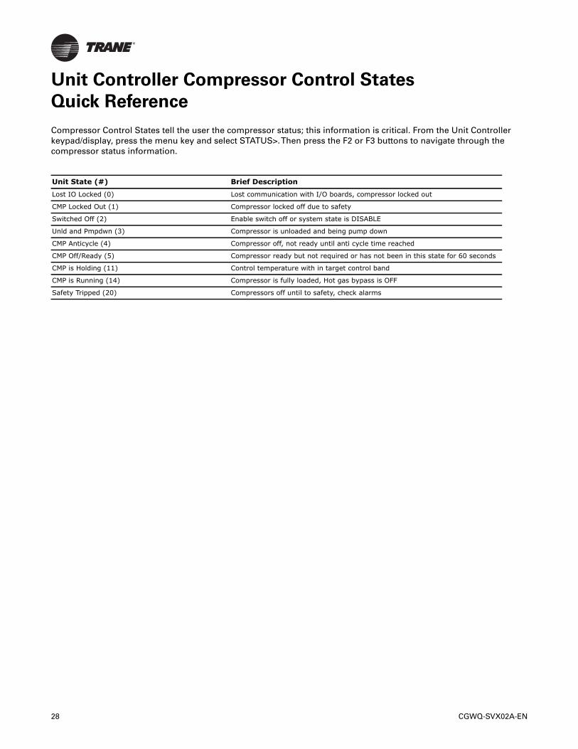
Unit Controller Compressor Control States
Quick Reference
Compressor Control States tell the user the compressor status; this information is critical. From the Unit Controllerkeypad/display, press the menu key and select STATUS>.Then press the F2 or F3 buttons to navigate through thecompressor status information.
Unit State (#) Brief Description
Lost IO Locked (0) Lost communication with I/O boards, compressor locked out
CMP Locked Out (1) Compressor locked off due to safety
Switched Off (2) Enable switch off or system state is DISABLE
Unld and Pmpdwn (3) Compressor is unloaded and being pump down
CMP Anticycle (4) Compressor off, not ready until anti cycle time reached
CMP Off/Ready (5) Compressor ready but not required or has not been in this state for 60 seconds
CMP is Holding (11) Control temperature with in target control band
CMP is Running (14) Compressor is fully loaded, Hot gas bypass is OFF
Safety Tripped (20) Compressors off until to safety, check alarms
CGWQ-SVX02A-EN 29
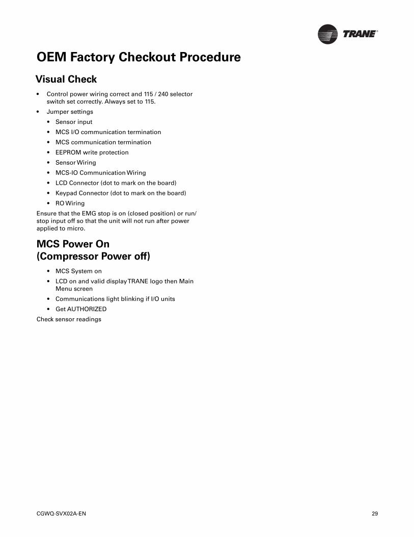
OEM Factory Checkout Procedure
Visual Check
• Control power wiring correct and 115 / 240 selectorswitch set correctly. Always set to 115.
• Jumper settings
• Sensor input
• MCS I/O communication termination
• MCS communication termination
• EEPROM write protection
• Sensor Wiring
• MCS-IO Communication Wiring
• LCD Connector (dot to mark on the board)
• Keypad Connector (dot to mark on the board)
• RO Wiring
Ensure that the EMG stop is on (closed position) or run/stop input off so that the unit will not run after powerapplied to micro.
MCS Power On
(Compressor Power off)
• MCS System on
• LCD on and valid displayTRANE logo then MainMenu screen
• Communications light blinking if I/O units
• Get AUTHORIZED
Check sensor readings
30 CGWQ-SVX02A-EN
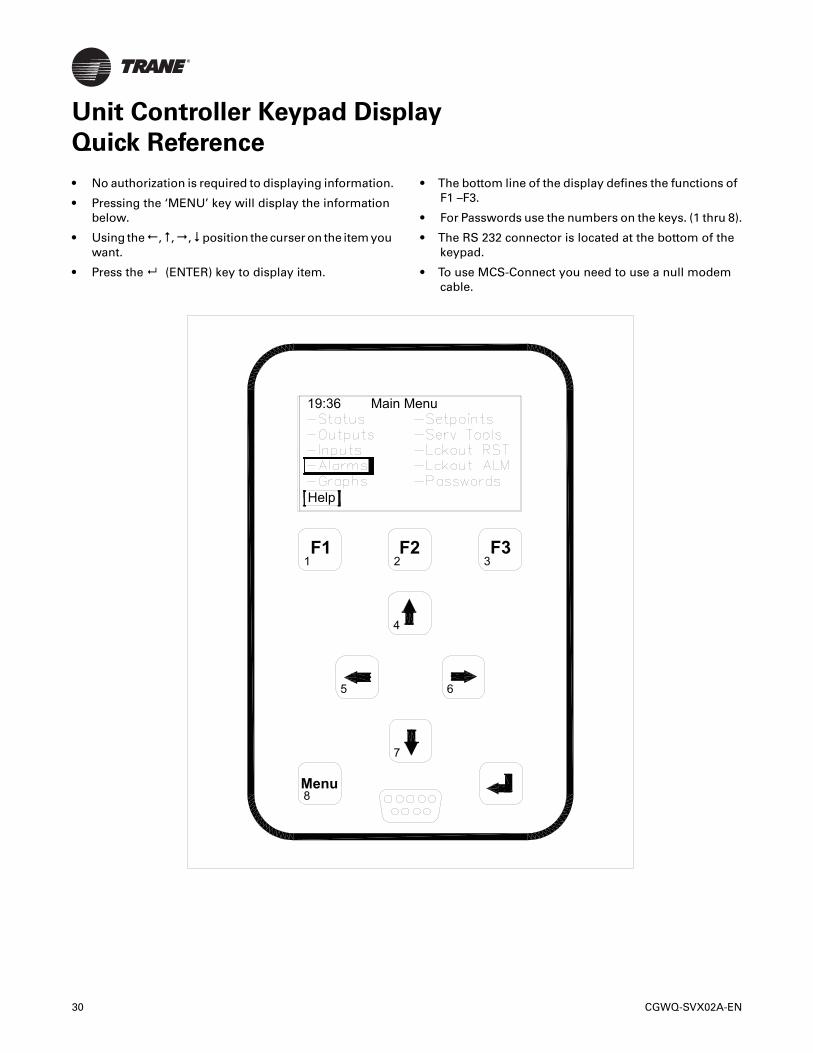
Unit Controller Keypad Display
Quick Reference
• No authorization is required to displaying information.
• Pressing the ‘MENU’ key will display the informationbelow.
• Using the,,,position the curser on the item youwant.
• Press the (ENTER) key to display item.
• The bottom line of the display defines the functions ofF1 –F3.
• For Passwords use the numbers on the keys. (1 thru 8).
• The RS 232 connector is located at the bottom of thekeypad.
• To use MCS-Connect you need to use a null modemcable.
Menu
7
5 6
4
1 2 3
4'-5
.30
3"
F2 F3F1
8
Help
19:36 Main Menu
CGWQ-SVX02A-EN 31
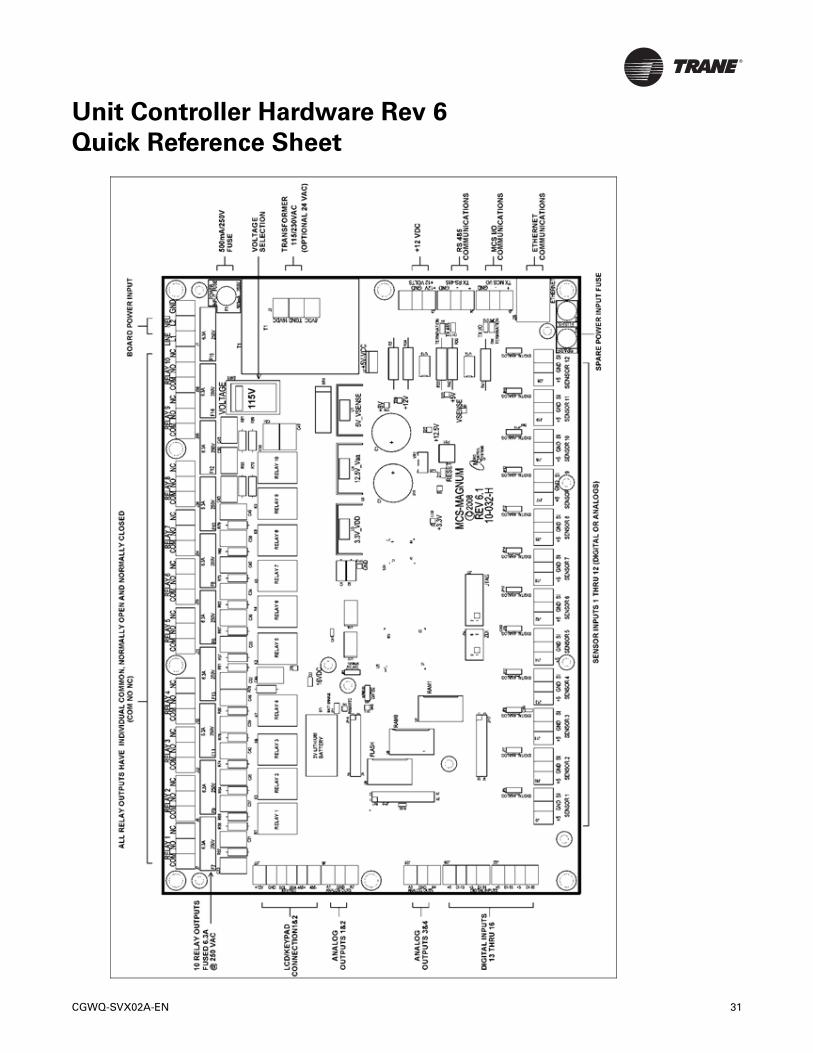
Unit Controller Hardware Rev 6
Quick Reference Sheet
32 CGWQ-SVX02A-EN
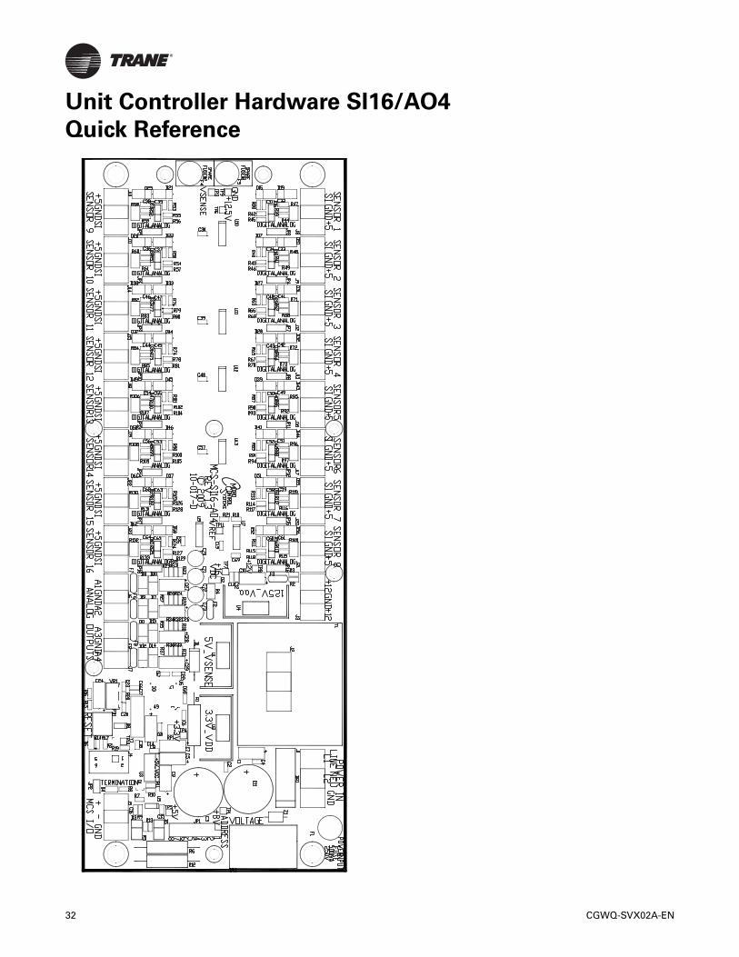
Unit Controller Hardware SI16/AO4
Quick Reference
CGWQ-SVX02A-EN 33
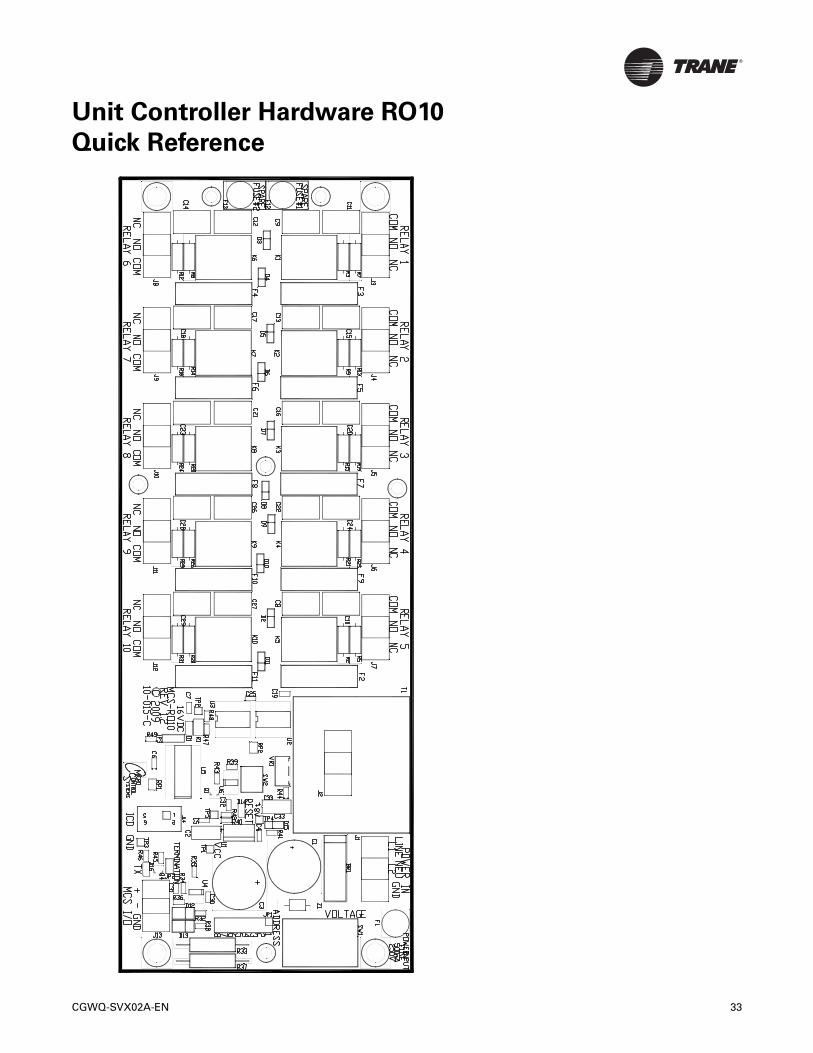
Unit Controller Hardware RO10
Quick Reference
34 CGWQ-SVX02A-EN
Unit Controller Quick Reference Sheet
(Temp and Humidity)
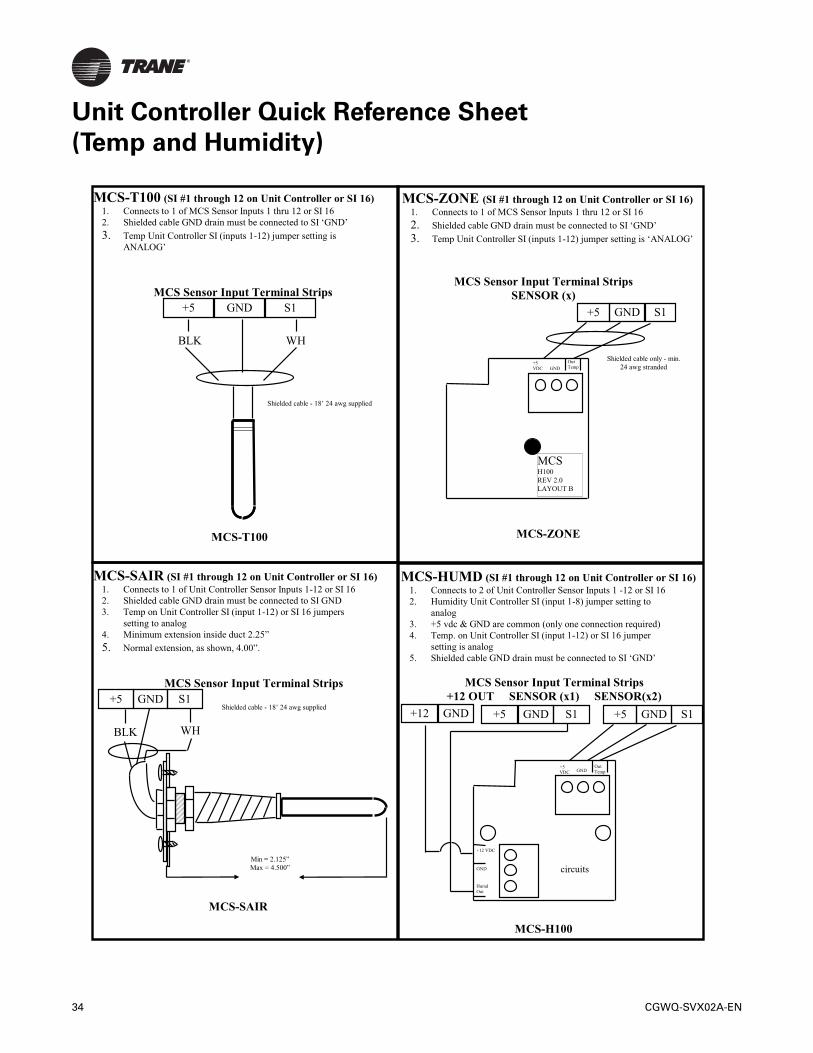
MCS-T100 (SI #1 through 12 on Unit Controller or SI 16)1. Connects to 1 of MCS Sensor Inputs 1 thru 12 or SI 162. Shielded cable GND drain must be connected to SI ‘GND’
3. Temp Unit Controller SI (inputs 1-12) jumper setting isANALOG’
MCS Sensor Input Terminal Strips
BLK WH
+5 GND S1
MCS-T100
Shielded cable - 18’ 24 awg supplied
MCS-SAIR (SI #1 through 12 on Unit Controller or SI 16)1. Connects to 1 of Unit Controller Sensor Inputs 1-12 or SI 162. Shielded cable GND drain must be connected to SI GND3. Temp on Unit Controller SI (input 1-12) or SI 16 jumpers
setting to analog4. Minimum extension inside duct 2.25”
5. Normal extension, as shown, 4.00”.
MCS Sensor Input Terminal Strips
BLK WH
+5 GND S1Shielded cable - 18’ 24 awg supplied
Min = 2.125”
Max = 4.500”
MCS-SAIR
MCS-ZONE (SI #1 through 12 on Unit Controller or SI 16)1. Connects to 1 of MCS Sensor Inputs 1 thru 12 or SI 162. Shielded cable GND drain must be connected to SI ‘GND’
3. Temp Unit Controller SI (inputs 1-12) jumper setting is ‘ANALOG’
MCS Sensor Input Terminal StripsSENSOR (x)
MCS-ZONE
MCS-HUMD (SI #1 through 12 on Unit Controller or SI 16)1. Connects to 2 of Unit Controller Sensor Inputs 1 -12 or SI 162. Humidity Unit Controller SI (input 1-8) jumper setting to
analog3. +5 vdc & GND are common (only one connection required)4. Temp. on Unit Controller SI (input 1-12) or SI 16 jumper
setting is analog5. Shielded cable GND drain must be connected to SI ‘GND’
MCS Sensor Input Terminal Strips+12 OUT SENSOR (x1) SENSOR(x2)
+12 GND +5 GND S1 +5 GND S1
+5 VDC GND
Out Temp
+12 VDC
GND
Humd Out
circuits
MCS-H100
+5 GND S1
+5 VDC GND
Out Temp
Shielded cable only - min. 24 awg stranded
MCSH100REV 2.0LAYOUT B
Unit Controller Quick Reference Sheet
(PSI, CT and Digital)
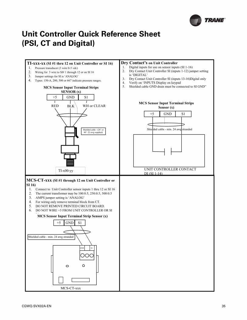
TI-xxx-xx (SI #1 thru 12 on Unit Controller or SI 16) 1. Pressure transducer (3 wire 0-5 vdc) 2. Wiring for 3 wire to SI# 1 through 12 or on SI 16 3. Jumper settings for SI is ‘ANALOG’ 4. Types: 150-A, 200, 500 or 667 indicate pressure ranges.
MCS Sensor Input Terminal Strips SENSOR (x)
RED WH or CLEAR
+5 GND S1
Shielded cable - (20’ or
40’ 22 awg supplied)
BLK
TI-x00-yy
Dry Contact’s on Unit Controller 1. Digital inputs for use on sensor inputs (SI 1-16) 2. Dry Contact Unit Controller SI (inputs 1-12) jumper setting
is ‘DIGITAL’ 3. Dry Contact Unit Controller SI (inputs 13-16)Digital only 4. Verify on ‘INPUTS Display on keypad 5. Shielded cable GND drain must be connected to SI GND”
+5 GND S1
MCS Sensor Input Terminal Strips Sensor (x)
Shielded cable - min. 24 awg stranded
UNIT CONTROLLER CONTACT DI (SI 1-14)
MCS-CT-xxx (SI #1 through 12 on Unit Controller or SI 16)
1. Connect to Unit Controller sensor inputs 1 thru 12 or SI 16 2. The current transformer may be 100:0.5, 250:0.5, 500:0.5 3. AMPS jumper setting is ‘ANALOG’ 4. For wiring only remove terminal block from CT. 5. DO NOT REMOVE PRINTED CIRCUIT BOARD. 6. DO NOT WIRE +5 FROM UNIT CONTROLLER OR SI
16
+5 GND S1
MCS Sensor Input Terminal Strip Sensor (x)
Shielded cable - min. 24 awg stranded
MCS-CT-xxx
GND S1
CGWQ-SVX02A-EN 35
Unit Controller Quick Reference Sheet (PSI, CT and Digital)
Note:
1. Sensor inputs should be shielded cable with shield tiedto ground on Unit Controller sensor input groundterminal.
2. The four digital inputs, on the Unit Controller printedcompressor board, do not require shielded cable.
All MCS boards with 24/120/240 vac must have groundswired from terminal directly to ground. (Do not jumpergrounds).
36 CGWQ-SVX02A-EN
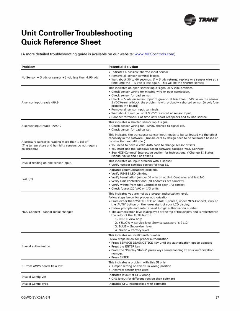
Unit ControllerTroubleshooting
Quick Reference Sheet
(A more detailed troubleshooting guide is available on our website: www.MCScontrols.com)
Problem Potential Solution
No Sensor + 5 vdc or sensor +5 vdc less than 4.90 vdc.
• Indicates a possible shorted input sensor• Remove all sensor terminal blocks.• Wait about 30 to 60 seconds. If + 5 vdc returns, replace one sensor wire at a
time until the + 5 vdc is lost again. This will be the shorted sensor.
A sensor input reads -99.9
This indicates an open sensor input signal or 5 VDC problem.• Check sensor wiring for missing wire or poor connection.• Check sensor for bad sensor.• Check + 5 vdc on sensor input to ground. If less than 5 VDC is on the sensor
5 VDC terminal block, the problem is with probably a shorted sensor. (A poly fuse protects the board)
• Remove all sensor input terminals.• Wait about 1 min. or until 5 VDC restored at sensor input.• Connect terminals 1 at time until short reappears and fix bad sensor.
A sensor input reads +999.9This indicates a shorted sensor input signal.• Check sensor wiring for +5VDC shorted to signal etc.• Check sensor for bad sensor.
A pressure sensor is reading more than 1 psi off(The temperature and humidity sensors do not require calibration.)
This indicates the transducer sensor input needs to be calibrated via the offset capability in the software. (Transducers by design need to be calibrated based on construction and altitude.)• You need to have a valid Auth code to change sensor offsets• You must use the Windows based software package ‘MCS-Connect’• See MCS-Connect’ Interactive section for instructions. (‘Change SI Status,
Manual Value and / or offset.)
Invalid reading on one sensor input.This indicates an input problem with 1 sensor.• Verify jumper settings correct for that SI.
Lost I/O
Indicates communications problem.• Verify RS485 LED blinking.• Verify termination jumper J6 only on at Unit Controller and last I/O.• Verify Unit Controller and I/O address’s set correctly.• Verify wiring from Unit Controller to each I/O correct.• Check fuses/120 VAC on I/O units
MCS-Connect– cannot make changes
This indicates you are not at a proper authorization level.Follow steps below for proper authorization• From either the SYSTEM INFO or STATUS screen, under MCS-Connect, click on
the ‘AUTH’ button on the lower right of your LCD display.• Follow prompts and enter a valid 4-digit authorization number.• The authorization level is displayed at the top of the display and is reflected via
the color of the AUTH button.1. RED = view only2. YELLOW = service level Service password is 21123. BLUE = Supervisor level4. Green = Factory level
Invalid authorization
This indicates an invalid auth number.Follow steps below for proper authorization• Press SERVICE DIAGNOSTICS key until the authorization option appears• Press the ENTER key• From the “Display Status” press keys corresponding to your authorization
number.• Press ENTER
SI from AMPS board 10 A lowThis indicates a problem with this SI only• Jumper setting on this SI in wrong position• Incorrect sensor type used
Invalid Config VerIndicates layout of CFG wrong• CFG layout for different version than software
Invalid Config Type Indicates CFG incompatible with software
CGWQ-SVX02A-EN 37
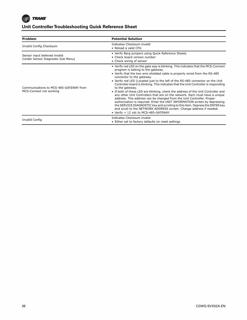
Unit ControllerTroubleshooting Quick Reference Sheet
Invalid Config ChecksumIndicates Checksum invalid• Reload a valid CFG
Sensor input believed invalid (Under Sensor Diagnostic Sub Menu)
• Verify Berg jumpers using Quick Reference Sheets• Check board version number• Check wiring of sensor
Communications to MCS-485-GATEWAY from MCS-Connect not working
• Verify red LED on the gate way is blinking. This indicates that the MCS-Connect program is talking to the gateway.
• Verify that the two wire shielded cable is properly wired from the RS-485 connector to the gateway.
• Verify red LED (Located just to the left of the RS-485 connector on the Unit Controller board is blinking. This indicates that the Unit Controller is responding to the gateway.
• If both of these LED are blinking, check the address of the Unit Controller and any other Unit Controllers that are on the network. Each must have a unique address. This address can be changed from the Unit Controller. Proper authorization is required. Enter the UNIT INFORMATION screen by depressing the SERVICE DIAGNOSTIC key and scrolling to this item. Depress the ENTER key and scroll to the NETWORK ADDRESS screen. Change address if needed.
• Verify + 12 vdc to MCS-485-GATEWAY
Invalid ConfigIndicates Checksum invalid• Either set to factory defaults on reset settings
Problem Potential Solution
38 CGWQ-SVX02A-EN
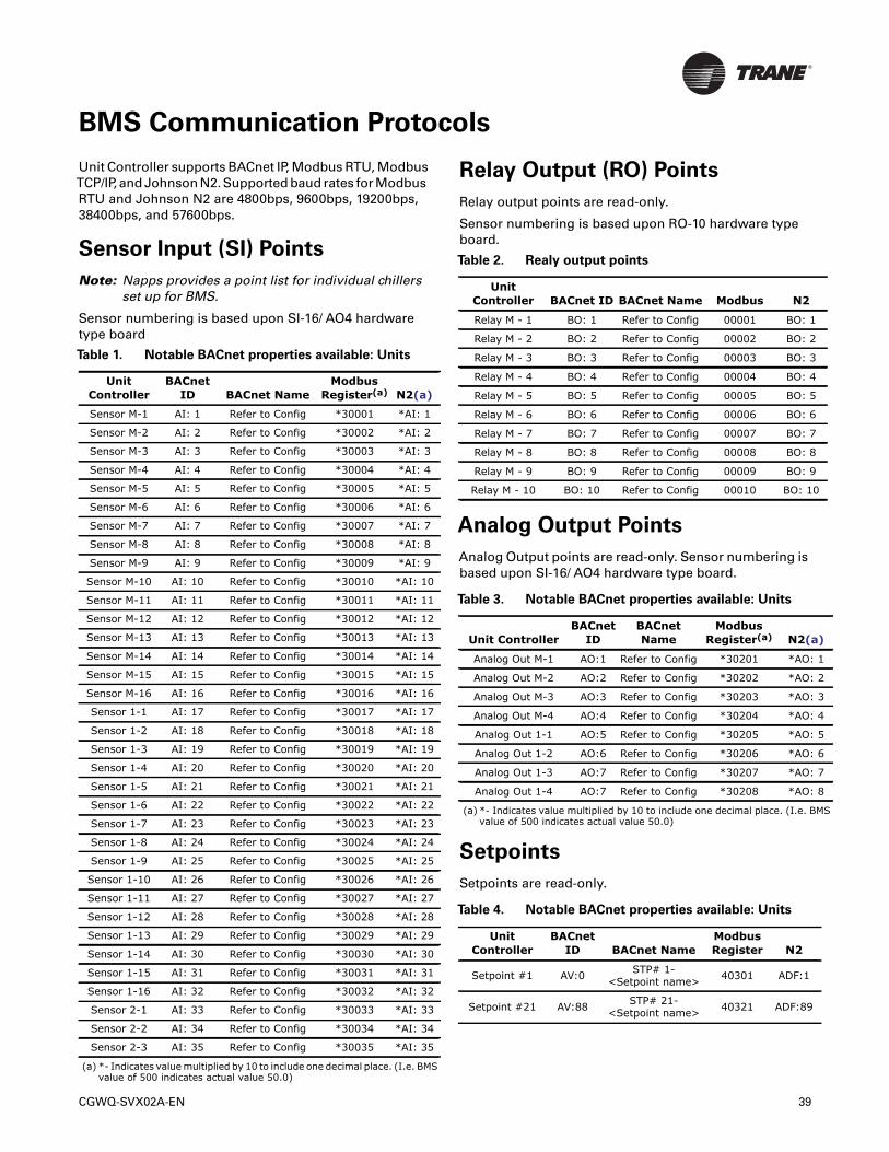
BMS Communication Protocols
Unit Controller supports BACnet IP, Modbus RTU, ModbusTCP/IP, and Johnson N2. Supported baud rates for ModbusRTU and Johnson N2 are 4800bps, 9600bps, 19200bps,38400bps, and 57600bps.
Sensor Input (SI) Points
Note: Napps provides a point list for individual chillersset up for BMS.
Sensor numbering is based upon SI-16/ AO4 hardwaretype board
Relay Output (RO) Points
Relay output points are read-only.
Sensor numbering is based upon RO-10 hardware typeboard.
Analog Output Points
Analog Output points are read-only. Sensor numbering isbased upon SI-16/ AO4 hardware type board.
Setpoints
Setpoints are read-only.
Table 1. Notable BACnet properties available: Units
Unit Controller
BACnet ID BACnet Name
Modbus Register(a)
(a) *- Indicates value multiplied by 10 to include one decimal place. (I.e. BMS value of 500 indicates actual value 50.0)
N2(a)
Sensor M-1 AI: 1 Refer to Config *30001 *AI: 1
Sensor M-2 AI: 2 Refer to Config *30002 *AI: 2
Sensor M-3 AI: 3 Refer to Config *30003 *AI: 3
Sensor M-4 AI: 4 Refer to Config *30004 *AI: 4
Sensor M-5 AI: 5 Refer to Config *30005 *AI: 5
Sensor M-6 AI: 6 Refer to Config *30006 *AI: 6
Sensor M-7 AI: 7 Refer to Config *30007 *AI: 7
Sensor M-8 AI: 8 Refer to Config *30008 *AI: 8
Sensor M-9 AI: 9 Refer to Config *30009 *AI: 9
Sensor M-10 AI: 10 Refer to Config *30010 *AI: 10
Sensor M-11 AI: 11 Refer to Config *30011 *AI: 11
Sensor M-12 AI: 12 Refer to Config *30012 *AI: 12
Sensor M-13 AI: 13 Refer to Config *30013 *AI: 13
Sensor M-14 AI: 14 Refer to Config *30014 *AI: 14
Sensor M-15 AI: 15 Refer to Config *30015 *AI: 15
Sensor M-16 AI: 16 Refer to Config *30016 *AI: 16
Sensor 1-1 AI: 17 Refer to Config *30017 *AI: 17
Sensor 1-2 AI: 18 Refer to Config *30018 *AI: 18
Sensor 1-3 AI: 19 Refer to Config *30019 *AI: 19
Sensor 1-4 AI: 20 Refer to Config *30020 *AI: 20
Sensor 1-5 AI: 21 Refer to Config *30021 *AI: 21
Sensor 1-6 AI: 22 Refer to Config *30022 *AI: 22
Sensor 1-7 AI: 23 Refer to Config *30023 *AI: 23
Sensor 1-8 AI: 24 Refer to Config *30024 *AI: 24
Sensor 1-9 AI: 25 Refer to Config *30025 *AI: 25
Sensor 1-10 AI: 26 Refer to Config *30026 *AI: 26
Sensor 1-11 AI: 27 Refer to Config *30027 *AI: 27
Sensor 1-12 AI: 28 Refer to Config *30028 *AI: 28
Sensor 1-13 AI: 29 Refer to Config *30029 *AI: 29
Sensor 1-14 AI: 30 Refer to Config *30030 *AI: 30
Sensor 1-15 AI: 31 Refer to Config *30031 *AI: 31
Sensor 1-16 AI: 32 Refer to Config *30032 *AI: 32
Sensor 2-1 AI: 33 Refer to Config *30033 *AI: 33
Sensor 2-2 AI: 34 Refer to Config *30034 *AI: 34
Sensor 2-3 AI: 35 Refer to Config *30035 *AI: 35
Table 2. Realy output points
Unit Controller BACnet ID BACnet Name Modbus N2
Relay M - 1 BO: 1 Refer to Config 00001 BO: 1
Relay M - 2 BO: 2 Refer to Config 00002 BO: 2
Relay M - 3 BO: 3 Refer to Config 00003 BO: 3
Relay M - 4 BO: 4 Refer to Config 00004 BO: 4
Relay M - 5 BO: 5 Refer to Config 00005 BO: 5
Relay M - 6 BO: 6 Refer to Config 00006 BO: 6
Relay M - 7 BO: 7 Refer to Config 00007 BO: 7
Relay M - 8 BO: 8 Refer to Config 00008 BO: 8
Relay M - 9 BO: 9 Refer to Config 00009 BO: 9
Relay M - 10 BO: 10 Refer to Config 00010 BO: 10
Table 3. Notable BACnet properties available: Units
Unit ControllerBACnet
IDBACnet Name
Modbus Register(a)
(a) *- Indicates value multiplied by 10 to include one decimal place. (I.e. BMSvalue of 500 indicates actual value 50.0)
N2(a)
Analog Out M-1 AO:1 Refer to Config *30201 *AO: 1
Analog Out M-2 AO:2 Refer to Config *30202 *AO: 2
Analog Out M-3 AO:3 Refer to Config *30203 *AO: 3
Analog Out M-4 AO:4 Refer to Config *30204 *AO: 4
Analog Out 1-1 AO:5 Refer to Config *30205 *AO: 5
Analog Out 1-2 AO:6 Refer to Config *30206 *AO: 6
Analog Out 1-3 AO:7 Refer to Config *30207 *AO: 7
Analog Out 1-4 AO:7 Refer to Config *30208 *AO: 8
Table 4. Notable BACnet properties available: Units
Unit Controller
BACnet ID BACnet Name
Modbus Register N2
Setpoint #1 AV:0 STP# 1-<Setpoint name> 40301 ADF:1
Setpoint #21 AV:88 STP# 21-<Setpoint name> 40321 ADF:89
CGWQ-SVX02A-EN 39
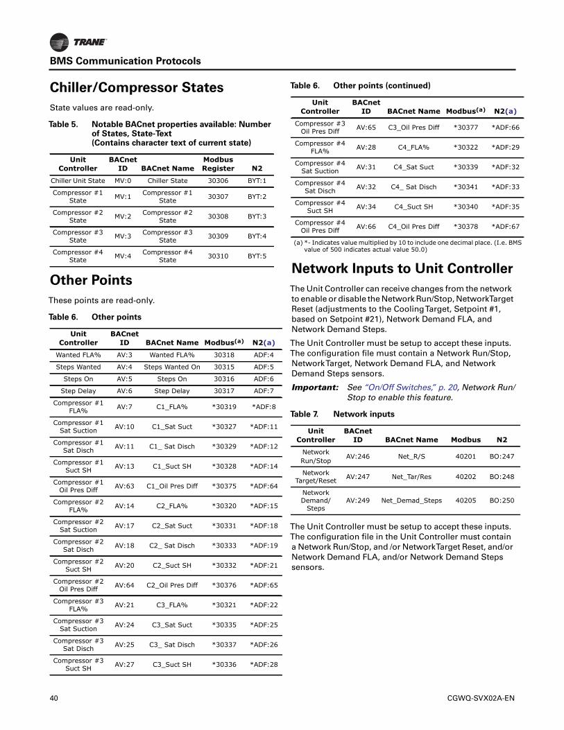
BMS Communication Protocols
Chiller/Compressor States
State values are read-only.
Other Points
These points are read-only.
Network Inputs to Unit Controller
The Unit Controller can receive changes from the networkto enable or disable the Network Run/Stop, NetworkTargetReset (adjustments to the CoolingTarget, Setpoint #1,based on Setpoint #21), Network Demand FLA, andNetwork Demand Steps.
The Unit Controller must be setup to accept these inputs.The configuration file must contain a Network Run/Stop,NetworkTarget, Network Demand FLA, and NetworkDemand Steps sensors.
Important: See “On/Off Switches,” p. 20, Network Run/Stop to enable this feature.
The Unit Controller must be setup to accept these inputs.The configuration file in the Unit Controller must containa Network Run/Stop, and /or NetworkTarget Reset, and/orNetwork Demand FLA, and/or Network Demand Stepssensors.
Table 5. Notable BACnet properties available: Numberof States, State-Text(Contains character text of current state)
Unit Controller
BACnet ID BACnet Name
Modbus Register N2
Chiller Unit State MV:0 Chiller State 30306 BYT:1
Compressor #1 State MV:1 Compressor #1
State 30307 BYT:2
Compressor #2 State MV:2 Compressor #2
State 30308 BYT:3
Compressor #3 State MV:3 Compressor #3
State 30309 BYT:4
Compressor #4 State MV:4 Compressor #4
State 30310 BYT:5
Table 6. Other points
Unit Controller
BACnet ID BACnet Name Modbus(a) N2(a)
Wanted FLA% AV:3 Wanted FLA% 30318 ADF:4
Steps Wanted AV:4 Steps Wanted On 30315 ADF:5
Steps On AV:5 Steps On 30316 ADF:6
Step Delay AV:6 Step Delay 30317 ADF:7
Compressor #1FLA% AV:7 C1_FLA% *30319 *ADF:8
Compressor #1Sat Suction AV:10 C1_Sat Suct *30327 *ADF:11
Compressor #1Sat Disch AV:11 C1_ Sat Disch *30329 *ADF:12
Compressor #1Suct SH AV:13 C1_Suct SH *30328 *ADF:14
Compressor #1 Oil Pres Diff AV:63 C1_Oil Pres Diff *30375 *ADF:64
Compressor #2 FLA% AV:14 C2_FLA% *30320 *ADF:15
Compressor #2 Sat Suction AV:17 C2_Sat Suct *30331 *ADF:18
Compressor #2 Sat Disch AV:18 C2_ Sat Disch *30333 *ADF:19
Compressor #2 Suct SH AV:20 C2_Suct SH *30332 *ADF:21
Compressor #2 Oil Pres Diff AV:64 C2_Oil Pres Diff *30376 *ADF:65
Compressor #3 FLA% AV:21 C3_FLA% *30321 *ADF:22
Compressor #3 Sat Suction AV:24 C3_Sat Suct *30335 *ADF:25
Compressor #3 Sat Disch AV:25 C3_ Sat Disch *30337 *ADF:26
Compressor #3 Suct SH AV:27 C3_Suct SH *30336 *ADF:28
Compressor #3 Oil Pres Diff AV:65 C3_Oil Pres Diff *30377 *ADF:66
Compressor #4 FLA% AV:28 C4_FLA% *30322 *ADF:29
Compressor #4 Sat Suction AV:31 C4_Sat Suct *30339 *ADF:32
Compressor #4 Sat Disch AV:32 C4_ Sat Disch *30341 *ADF:33
Compressor #4 Suct SH AV:34 C4_Suct SH *30340 *ADF:35
Compressor #4 Oil Pres Diff AV:66 C4_Oil Pres Diff *30378 *ADF:67
(a) *- Indicates value multiplied by 10 to include one decimal place. (I.e. BMS value of 500 indicates actual value 50.0)
Table 7. Network inputs
Unit Controller
BACnet ID BACnet Name Modbus N2
NetworkRun/Stop
AV:246 Net_R/S 40201 BO:247
Network Target/Reset AV:247 Net_Tar/Res 40202 BO:248
Network Demand/
StepsAV:249 Net_Demad_Steps 40205 BO:250
Table 6. Other points (continued)
Unit Controller
BACnet ID BACnet Name Modbus(a) N2(a)
40 CGWQ-SVX02A-EN
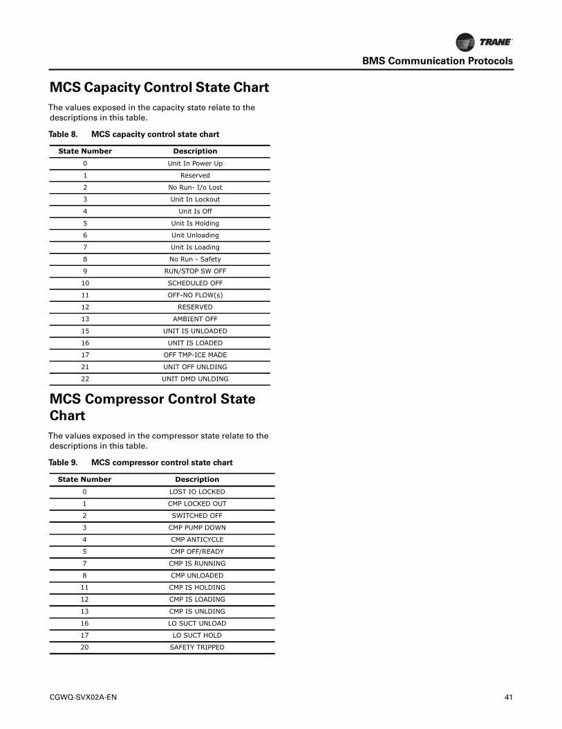
BMS Communication Protocols
MCS Capacity Control State Chart
The values exposed in the capacity state relate to thedescriptions in this table.
MCS Compressor Control State
Chart
The values exposed in the compressor state relate to thedescriptions in this table.
Table 8. MCS capacity control state chart
State Number Description
0 Unit In Power Up
1 Reserved
2 No Run- I/o Lost
3 Unit In Lockout
4 Unit Is Off
5 Unit Is Holding
6 Unit Unloading
7 Unit Is Loading
8 No Run - Safety
9 RUN/STOP SW OFF
10 SCHEDULED OFF
11 OFF-NO FLOW(s)
12 RESERVED
13 AMBIENT OFF
15 UNIT IS UNLOADED
16 UNIT IS LOADED
17 OFF TMP-ICE MADE
21 UNIT OFF UNLDING
22 UNIT DMD UNLDING
Table 9. MCS compressor control state chart
State Number Description
0 LOST IO LOCKED
1 CMP LOCKED OUT
2 SWITCHED OFF
3 CMP PUMP DOWN
4 CMP ANTICYCLE
5 CMP OFF/READY
7 CMP IS RUNNING
8 CMP UNLOADED
11 CMP IS HOLDING
12 CMP IS LOADING
13 CMP IS UNLDING
16 LO SUCT UNLOAD
17 LO SUCT HOLD
20 SAFETY TRIPPED
CGWQ-SVX02A-EN 41
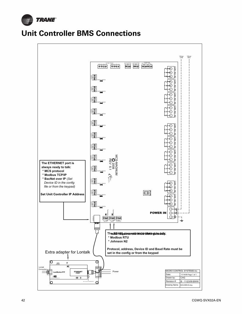
Unit Controller BMS Connections
Set Unit Controller IP Address
now requires the MCS BMS gateway.
42 CGWQ-SVX02A-EN
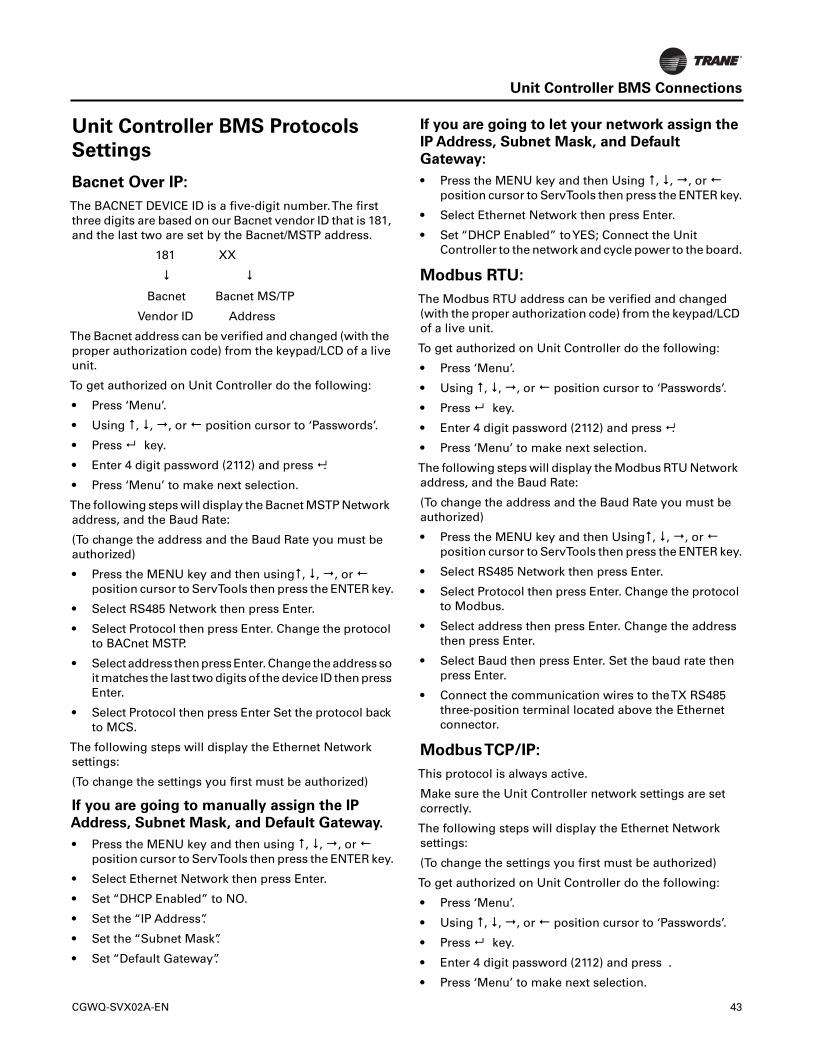
Unit Controller BMS Connections
Unit Controller BMS Protocols
Settings
Bacnet Over IP:
The BACNET DEVICE ID is a five-digit number.The firstthree digits are based on our Bacnet vendor ID that is 181,and the last two are set by the Bacnet/MSTP address.
181 XX
Bacnet Bacnet MS/TP
Vendor ID Address
The Bacnet address can be verified and changed (with theproper authorization code) from the keypad/LCD of a liveunit.
To get authorized on Unit Controller do the following:
• Press ‘Menu’.
• Using , , , or position cursor to ‘Passwords’.
• Press key.
• Enter 4 digit password (2112) and press .
• Press ‘Menu’ to make next selection.
The following steps will display the Bacnet MSTP Networkaddress, and the Baud Rate:
(To change the address and the Baud Rate you must beauthorized)
• Press the MENU key and then using, , , or position cursor to ServTools then press the ENTER key.
• Select RS485 Network then press Enter.
• Select Protocol then press Enter. Change the protocolto BACnet MSTP.
• Select address then press Enter. Change the address soit matches the last two digits of the device ID then pressEnter.
• Select Protocol then press Enter Set the protocol backto MCS.
The following steps will display the Ethernet Networksettings:
(To change the settings you first must be authorized)
If you are going to manually assign the IP
Address, Subnet Mask, and Default Gateway.
• Press the MENU key and then using , , , or position cursor to ServTools then press the ENTER key.
• Select Ethernet Network then press Enter.
• Set “DHCP Enabled” to NO.
• Set the “IP Address”.
• Set the “Subnet Mask”.
• Set “Default Gateway”.
If you are going to let your network assign the
IP Address, Subnet Mask, and Default
Gateway:
• Press the MENU key and then Using , , , or position cursor to ServTools then press the ENTER key.
• Select Ethernet Network then press Enter.
• Set “DHCP Enabled” toYES; Connect the UnitController to the network and cycle power to the board.
Modbus RTU:
The Modbus RTU address can be verified and changed(with the proper authorization code) from the keypad/LCDof a live unit.
To get authorized on Unit Controller do the following:
• Press ‘Menu’.
• Using , , , or position cursor to ‘Passwords’.
• Press key.
• Enter 4 digit password (2112) and press .
• Press ‘Menu’ to make next selection.
The following steps will display the Modbus RTU Networkaddress, and the Baud Rate:
(To change the address and the Baud Rate you must beauthorized)
• Press the MENU key and then Using, , , or position cursor to ServTools then press the ENTER key.
• Select RS485 Network then press Enter.
• Select Protocol then press Enter. Change the protocolto Modbus.
• Select address then press Enter. Change the addressthen press Enter.
• Select Baud then press Enter. Set the baud rate thenpress Enter.
• Connect the communication wires to theTX RS485three-position terminal located above the Ethernetconnector.
ModbusTCP/IP:
This protocol is always active.
Make sure the Unit Controller network settings are setcorrectly.
The following steps will display the Ethernet Networksettings:
(To change the settings you first must be authorized)
To get authorized on Unit Controller do the following:
• Press ‘Menu’.
• Using , , , or position cursor to ‘Passwords’.
• Press key.
• Enter 4 digit password (2112) and press .
• Press ‘Menu’ to make next selection.
CGWQ-SVX02A-EN 43
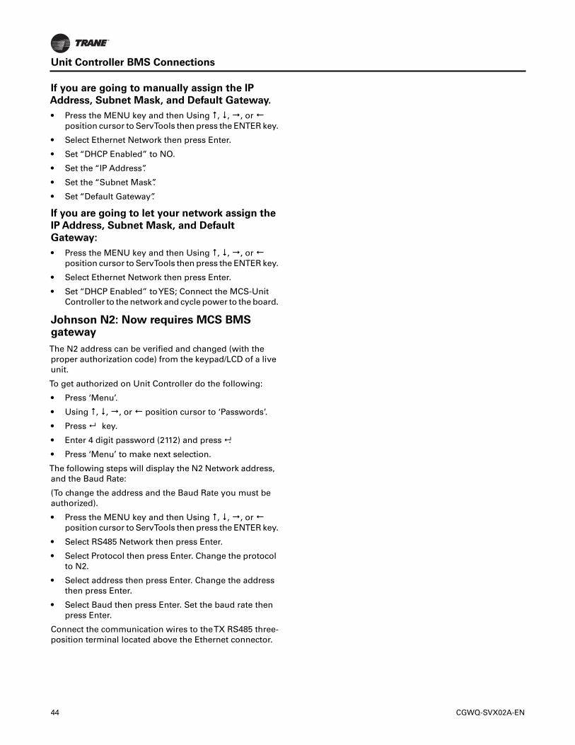
Unit Controller BMS Connections
If you are going to manually assign the IP
Address, Subnet Mask, and Default Gateway.
• Press the MENU key and then Using , , , or position cursor to ServTools then press the ENTER key.
• Select Ethernet Network then press Enter.
• Set “DHCP Enabled” to NO.
• Set the “IP Address”.
• Set the “Subnet Mask”.
• Set “Default Gateway”.
If you are going to let your network assign the
IP Address, Subnet Mask, and Default
Gateway:
• Press the MENU key and then Using , , , or position cursor to ServTools then press the ENTER key.
• Select Ethernet Network then press Enter.
• Set “DHCP Enabled” toYES; Connect the MCS-UnitController to the network and cycle power to the board.
Johnson N2: Now requires MCS BMSgateway
The N2 address can be verified and changed (with theproper authorization code) from the keypad/LCD of a liveunit.
To get authorized on Unit Controller do the following:
• Press ‘Menu’.
• Using , , , or position cursor to ‘Passwords’.
• Press key.
• Enter 4 digit password (2112) and press .
• Press ‘Menu’ to make next selection.
The following steps will display the N2 Network address,and the Baud Rate:
(To change the address and the Baud Rate you must beauthorized).
• Press the MENU key and then Using , , , or position cursor to ServTools then press the ENTER key.
• Select RS485 Network then press Enter.
• Select Protocol then press Enter. Change the protocolto N2.
• Select address then press Enter. Change the addressthen press Enter.
• Select Baud then press Enter. Set the baud rate thenpress Enter.
Connect the communication wires to theTX RS485 three-position terminal located above the Ethernet connector.
44 CGWQ-SVX02A-EN
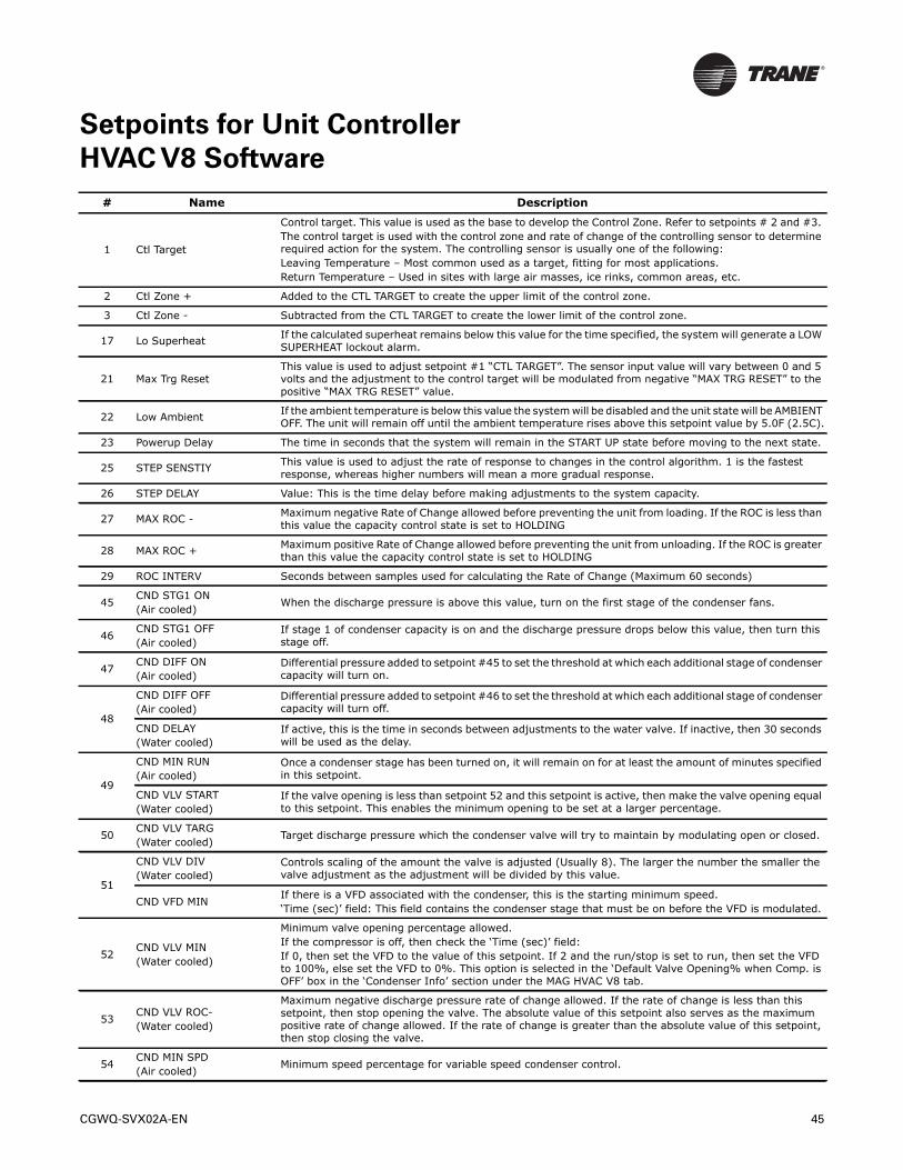
Setpoints for Unit Controller
HVAC V8 Software
# Name Description
1 Ctl Target
Control target. This value is used as the base to develop the Control Zone. Refer to setpoints # 2 and #3. The control target is used with the control zone and rate of change of the controlling sensor to determine required action for the system. The controlling sensor is usually one of the following:Leaving Temperature – Most common used as a target, fitting for most applications.Return Temperature – Used in sites with large air masses, ice rinks, common areas, etc.
2 Ctl Zone + Added to the CTL TARGET to create the upper limit of the control zone.
3 Ctl Zone - Subtracted from the CTL TARGET to create the lower limit of the control zone.
17 Lo Superheat If the calculated superheat remains below this value for the time specified, the system will generate a LOW SUPERHEAT lockout alarm.
21 Max Trg ResetThis value is used to adjust setpoint #1 “CTL TARGET”. The sensor input value will vary between 0 and 5 volts and the adjustment to the control target will be modulated from negative “MAX TRG RESET” to the positive “MAX TRG RESET” value.
22 Low Ambient If the ambient temperature is below this value the system will be disabled and the unit state will be AMBIENT OFF. The unit will remain off until the ambient temperature rises above this setpoint value by 5.0F (2.5C).
23 Powerup Delay The time in seconds that the system will remain in the START UP state before moving to the next state.
25 STEP SENSTIY This value is used to adjust the rate of response to changes in the control algorithm. 1 is the fastest response, whereas higher numbers will mean a more gradual response.
26 STEP DELAY Value: This is the time delay before making adjustments to the system capacity.
27 MAX ROC - Maximum negative Rate of Change allowed before preventing the unit from loading. If the ROC is less than this value the capacity control state is set to HOLDING
28 MAX ROC + Maximum positive Rate of Change allowed before preventing the unit from unloading. If the ROC is greater than this value the capacity control state is set to HOLDING
29 ROC INTERV Seconds between samples used for calculating the Rate of Change (Maximum 60 seconds)
45CND STG1 ON(Air cooled)
When the discharge pressure is above this value, turn on the first stage of the condenser fans.
46CND STG1 OFF(Air cooled)
If stage 1 of condenser capacity is on and the discharge pressure drops below this value, then turn this stage off.
47CND DIFF ON(Air cooled)
Differential pressure added to setpoint #45 to set the threshold at which each additional stage of condenser capacity will turn on.
48
CND DIFF OFF(Air cooled)
Differential pressure added to setpoint #46 to set the threshold at which each additional stage of condenser capacity will turn off.
CND DELAY(Water cooled)
If active, this is the time in seconds between adjustments to the water valve. If inactive, then 30 seconds will be used as the delay.
49
CND MIN RUN(Air cooled)
Once a condenser stage has been turned on, it will remain on for at least the amount of minutes specified in this setpoint.
CND VLV START(Water cooled)
If the valve opening is less than setpoint 52 and this setpoint is active, then make the valve opening equal to this setpoint. This enables the minimum opening to be set at a larger percentage.
50CND VLV TARG(Water cooled)
Target discharge pressure which the condenser valve will try to maintain by modulating open or closed.
51
CND VLV DIV(Water cooled)
Controls scaling of the amount the valve is adjusted (Usually 8). The larger the number the smaller the valve adjustment as the adjustment will be divided by this value.
CND VFD MINIf there is a VFD associated with the condenser, this is the starting minimum speed.‘Time (sec)’ field: This field contains the condenser stage that must be on before the VFD is modulated.
52CND VLV MIN(Water cooled)
Minimum valve opening percentage allowed.If the compressor is off, then check the ‘Time (sec)’ field: If 0, then set the VFD to the value of this setpoint. If 2 and the run/stop is set to run, then set the VFD to 100%, else set the VFD to 0%. This option is selected in the ‘Default Valve Opening% when Comp. is OFF’ box in the ‘Condenser Info’ section under the MAG HVAC V8 tab.
53CND VLV ROC-(Water cooled)
Maximum negative discharge pressure rate of change allowed. If the rate of change is less than this setpoint, then stop opening the valve. The absolute value of this setpoint also serves as the maximum positive rate of change allowed. If the rate of change is greater than the absolute value of this setpoint, then stop closing the valve.
54CND MIN SPD(Air cooled)
Minimum speed percentage for variable speed condenser control.
CGWQ-SVX02A-EN 45
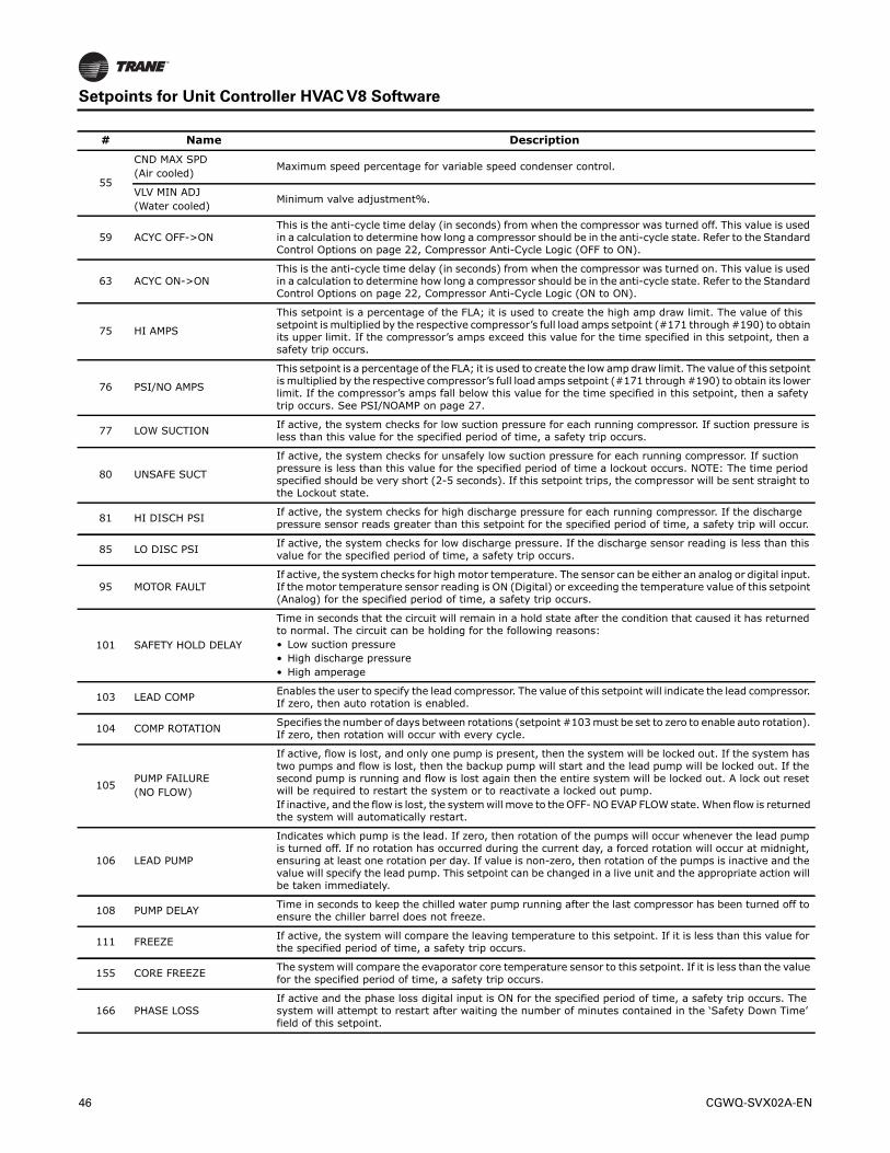
Setpoints for Unit Controller HVAC V8 Software
55
CND MAX SPD(Air cooled)
Maximum speed percentage for variable speed condenser control.
VLV MIN ADJ(Water cooled)
Minimum valve adjustment%.
59 ACYC OFF->ONThis is the anti-cycle time delay (in seconds) from when the compressor was turned off. This value is used in a calculation to determine how long a compressor should be in the anti-cycle state. Refer to the Standard Control Options on page 22, Compressor Anti-Cycle Logic (OFF to ON).
63 ACYC ON->ONThis is the anti-cycle time delay (in seconds) from when the compressor was turned on. This value is used in a calculation to determine how long a compressor should be in the anti-cycle state. Refer to the Standard Control Options on page 22, Compressor Anti-Cycle Logic (ON to ON).
75 HI AMPS
This setpoint is a percentage of the FLA; it is used to create the high amp draw limit. The value of this setpoint is multiplied by the respective compressor’s full load amps setpoint (#171 through #190) to obtain its upper limit. If the compressor’s amps exceed this value for the time specified in this setpoint, then a safety trip occurs.
76 PSI/NO AMPS
This setpoint is a percentage of the FLA; it is used to create the low amp draw limit. The value of this setpoint is multiplied by the respective compressor’s full load amps setpoint (#171 through #190) to obtain its lower limit. If the compressor’s amps fall below this value for the time specified in this setpoint, then a safety trip occurs. See PSI/NOAMP on page 27.
77 LOW SUCTION If active, the system checks for low suction pressure for each running compressor. If suction pressure is less than this value for the specified period of time, a safety trip occurs.
80 UNSAFE SUCT
If active, the system checks for unsafely low suction pressure for each running compressor. If suction pressure is less than this value for the specified period of time a lockout occurs. NOTE: The time period specified should be very short (2-5 seconds). If this setpoint trips, the compressor will be sent straight to the Lockout state.
81 HI DISCH PSI If active, the system checks for high discharge pressure for each running compressor. If the discharge pressure sensor reads greater than this setpoint for the specified period of time, a safety trip will occur.
85 LO DISC PSI If active, the system checks for low discharge pressure. If the discharge sensor reading is less than this value for the specified period of time, a safety trip occurs.
95 MOTOR FAULTIf active, the system checks for high motor temperature. The sensor can be either an analog or digital input. If the motor temperature sensor reading is ON (Digital) or exceeding the temperature value of this setpoint (Analog) for the specified period of time, a safety trip occurs.
101 SAFETY HOLD DELAY
Time in seconds that the circuit will remain in a hold state after the condition that caused it has returned to normal. The circuit can be holding for the following reasons:• Low suction pressure• High discharge pressure • High amperage
103 LEAD COMP Enables the user to specify the lead compressor. The value of this setpoint will indicate the lead compressor. If zero, then auto rotation is enabled.
104 COMP ROTATION Specifies the number of days between rotations (setpoint #103 must be set to zero to enable auto rotation). If zero, then rotation will occur with every cycle.
105PUMP FAILURE(NO FLOW)
If active, flow is lost, and only one pump is present, then the system will be locked out. If the system has two pumps and flow is lost, then the backup pump will start and the lead pump will be locked out. If the second pump is running and flow is lost again then the entire system will be locked out. A lock out reset will be required to restart the system or to reactivate a locked out pump.If inactive, and the flow is lost, the system will move to the OFF- NO EVAP FLOW state. When flow is returned the system will automatically restart.
106 LEAD PUMP
Indicates which pump is the lead. If zero, then rotation of the pumps will occur whenever the lead pump is turned off. If no rotation has occurred during the current day, a forced rotation will occur at midnight, ensuring at least one rotation per day. If value is non-zero, then rotation of the pumps is inactive and the value will specify the lead pump. This setpoint can be changed in a live unit and the appropriate action will be taken immediately.
108 PUMP DELAY Time in seconds to keep the chilled water pump running after the last compressor has been turned off to ensure the chiller barrel does not freeze.
111 FREEZE If active, the system will compare the leaving temperature to this setpoint. If it is less than this value for the specified period of time, a safety trip occurs.
155 CORE FREEZE The system will compare the evaporator core temperature sensor to this setpoint. If it is less than the value for the specified period of time, a safety trip occurs.
166 PHASE LOSSIf active and the phase loss digital input is ON for the specified period of time, a safety trip occurs. The system will attempt to restart after waiting the number of minutes contained in the ‘Safety Down Time’ field of this setpoint.
# Name Description
46 CGWQ-SVX02A-EN
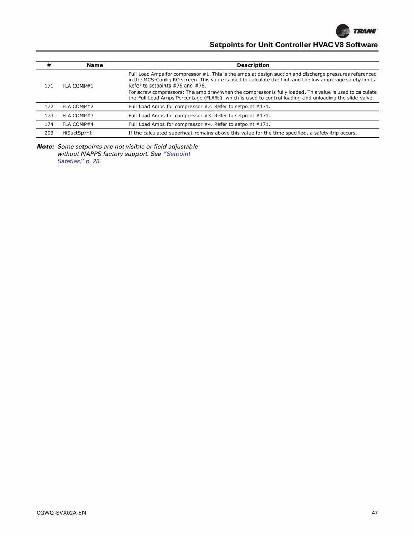
Setpoints for Unit Controller HVAC V8 Software
Note: Some setpoints are not visible or field adjustablewithout NAPPS factory support. See “SetpointSafeties,” p. 25.
171 FLA COMP#1
Full Load Amps for compressor #1. This is the amps at design suction and discharge pressures referenced in the MCS-Config RO screen. This value is used to calculate the high and the low amperage safety limits. Refer to setpoints #75 and #76.For screw compressors: The amp draw when the compressor is fully loaded. This value is used to calculate the Full Load Amps Percentage (FLA%), which is used to control loading and unloading the slide valve.
172 FLA COMP#2 Full Load Amps for compressor #2. Refer to setpoint #171.
173 FLA COMP#3 Full Load Amps for compressor #3. Refer to setpoint #171.
174 FLA COMP#4 Full Load Amps for compressor #4. Refer to setpoint #171.
203 HiSuctSprHt If the calculated superheat remains above this value for the time specified, a safety trip occurs.
# Name Description
CGWQ-SVX02A-EN 47

Trane optimizes the performance of homes and buildings around the world. A business of Ingersoll Rand, the leader increating and sustaining safe, comfortable and energy efficient environments,Trane offers a broad portfolio of advancedcontrols and HVAC systems, comprehensive building services, and parts. For more information, visit www.Trane.com.
Trane has a policy of continuous product and product data improvement and reserves the right to change design and specifications without notice.
We are committed to using environmentally
conscious print practices that reduce waste.
© 2014Trane All rights reserved
CGWQ-SVX02A-EN 12 Mar 2014
(NEW)