unit iv-basics of measurement and instrumentation part … · unit iv-basics of measurement and...
TRANSCRIPT
UNIT IV- BASICS OF MEASUREMENT AND INSTRUMENTATIONPART A
1. Write the staticcharacteristics of measurement. (N/D 15) (N/D 13)Accuracy, precision, sensitivity, linearity, Repeatablity.2. Define static error in measurements. ( N/D 14)Static error is defined as the difference between the measured value and the true value of the quantityunder measurement. A = Am -At, Where, A - Absolute static error of quantity, At - true value ofquantity, Am - Measured value of quantity.3. What is a transducer? Give example.( N/D 14 M/J 13)Transducer is a device which converts the physical quantity into an electrical quantity.ex: Thermocouple - which converts the temperature into voltage.4. What is an LVDT? What are the advantages of LVDT? (M/J 16 N/D 13)
It is a three coil inductive transducer operated in the differential mode. It consists of a primary coiland two secondary coil windings on a cylindrical former. The primary coil is connected to an alternatingsource whereas the differential output is taken from the two secondary coils.Advantages:
Wide range of linearity, Change of phase by 180 Deg When the core passes through the centerposition, Full-scale displacement is 0.1- 250mm, Sensitivity is 0.5- 2 mV.
5.A Thermistor has a resistance temperature coefficient β of -5%/ºC. If the resistance of thethermistor is 100Ω at ºC ,What is the resistance at º C? (A/M 15)Temp difference=35-25=10 deg Decrease per degree=5% soOhmic Decrease 5*10=50 ΩResistance at 35º C = 100-50=50Ω6. What is a piezoelectric effect?(A/M 15)(N/D16)When a piezoelectric material is subjected to stress or force, it generates an electrical potential or voltageproportional to the magnitude of the force. This makes this type of transducer ideal as a converter ofmechanical energy or force into electric potential..7.What is a Thermistor? Where do you deploy it. (N/D15) (M/J 13)Thermistor is a non metallic resistor used to measure the variation of temperature with lower powerdissipation. Temperature sensing applications8. Define accuracy and resolution of a measuring instrument.(N/D16)Accuracy of a measurement system is the degree of closeness of measurements of a quantity to thatquantity's true value.Resolution is the ability of the measurement system to detect and faithfully indicate small changes in thecharacteristic of the measurement result.9. How is the dynamic behavior of a measuring system determined? Name any common inputs tothe system? (M/J 16)The dynamic characteristics of any measurement system are (i)Speed of response and Response time(ii)Lag (iii) Fidelity (iv) Dynamic error

STATIC & DYNAMIC CHARACTERISTICS OF MEASUREMENT SYSTEM
The performance characteristics of an instrument are mainly divided into two categories:
i) Static characteristics
ii) Dynamic characteristics
Static characteristics:
The set of criteria defined for the instruments, which are used to measure the quantities which
are slowly varying with time or mostly constant, i.e., do not vary with time, is called ‘static
characteristics’.
The various static characteristics are:
i) Accuracy
ii) Precision
iii) Sensitivity
iv) Linearity
v) Reproducibility
vi) Repeatability
vii) Resolution
viii) Threshold
ix) Drift
x) Stability
xi) Tolerance
xii) Range or span
Accuracy:
It is the degree of closeness with which the reading approaches the true value of the quantity to

be measured. The accuracy can be expressed in following ways:
a) Point accuracy:
Such accuracy is specified at only one particular point of scale.
It does not give any information about the accuracy at any other Point on the scale.
b) Accuracy as percentage of scale span:
When an instrument as uniform scale, its accuracy may be expressed in terms of scale range.
c) Accuracy as percentage of true value:
The best way to conceive the idea of accuracy is to specify it interms of the true value of the
quantity being measured.
Precision: It is the measure of reproducibility i.e., given a fixed value of a quantity, precision is a
measure of the degree of agreement within a group of measurements. The precision is composed
of two characteristics:
a) Conformity:
Consider a resistor having true value as 2385692 , which is being measured by an ohmmeter. But
the reader can read consistently, a value as 2.4 M due to the nonavailability of proper scale. The
error created due to the limitation of the scale reading is a precision error.
b) Number of significant figures:
The precision of the measurement is obtained from the number of significant figures, in which
the reading is expressed. The significant figures convey the actual information about the
magnitude & the measurement precision of the quantity. The precision can be mathematically
expressed as:
Where, P = precision
Xn = Value of nth measurement
Xn = Average value the set of measurement values
Sensitivity:

The sensitivity denotes the smallest change in the measured variable to which the instrument
responds. It is defined as the ratio of the changes in the output of an instrument to a change in the
value of the quantity to be measured. Mathematically it is expressed as,
Thus, if the calibration curve is liner, as shown, the sensitivity of the instrument is the slope of
the calibration curve. If the calibration curve is not linear as shown, then the sensitivity varies
with the input. Inverse sensitivity or deflection factor is defined as the reciprocal of sensitivity.
Inverse sensitivity or deflection factor = 1/ sensitivity

Reproducibility:
It is the degree of closeness with which a given value may be repeatedly measured. It is specified
in terms of scale readings over a given period of time.
Repeatability:
It is defined as the variation of scale reading & random in nature
Drift: Drift may be classified into three categories:
a) zero drift:
If the whole calibration gradually shifts due to slippage, permanent set, or due to undue warming
up of electronic tube circuits, zero drift sets in.

b) span drift or sensitivity drift
If there is proportional change in the indication all along the upward scale, the drifts is called
span drift or sensitivity drift.
c) Zonal drift:
In case the drift occurs only a portion of span of an instrument, it is called zonal drift.
Resolution:
If the input is slowly increased from some arbitrary input value, it will again be found that output
does not change at all until a certain increment is exceeded. This increment is called resolution.
Threshold:
If the instrument input is increased very gradually from zero there will be some minimum value
below which no output change can be detected. This minimum value defines the threshold of the
instrument.
Stability:
It is the ability of an instrument to retain its performance throughout is
specified operating life.
Tolerance:
The maximum allowable error in the measurement is specified in terms of some value which is

called tolerance.
Range or span:
The minimum & maximum values of a quantity for which an instrument is designed to measure
is called its range or span.
DYNAMIC CHARACTERISTICS:
The set of criteria defined for the instruments, which changes rapidly with time, is
called ‘dynamic characteristics’.
The various dynamic characteristics are:
i) Speed of response
ii) Measuring lag
iii) Fidelity
iv) Dynamic error
Speed of response:
It is defined as the rapidity with which a measurement system responds to changes in the
measured quantity.
Measuring lag:
It is the retardation or delay in the response of a measurement system to changes in the measured
quantity. The measuring lags are of two types:
a) Retardation type:
In this case the response of the measurement system begins immediately after the change in
measured quantity has occurred.
b) Time delay lag :
In this case the response of the measurement system begins after a dead time after the application
of the input.
Fidelity:
It is defined as the degree to which a measurement system indicates changes in the measured
quantity without dynamic error.
Dynamic error:
It is the difference between the true value of the quantity changing with time & the value

indicated by the measurement system if no static error is assumed. It is also called measurement
error.
CLASSIFICATION OF ERRORS
Errors will creep into all measurement regardless of the care which is exerted. But it is
important for the person performing the experiment to take proper care so that the error can be
minimized. Some of the errors are of random in nature, some will be due to gross blunder on the
part of the experimenter and other will be due to the unknown reasons which are constant in
nature.Thus, we see that there are different sources of errors and generally errors are classified
mainly into three categories as follows:
(a) Gross errors
(b) Systematic errors
(c) Random errors
Gross Errors
These errors are due to the gross blunder on the part of the experimenters or observers.
These errors are caused by mistake in using instruments, recording data and calculating
measurement results. For example: A person may read a pressure gage indicating1.01 N/m2 as
1.10 N/m2. Someone may have a bad habit of memorizing data at a time of reading and writing a
number of data together at later time. This may cause error in the data. Errors may be made in
calculating the final results. Another gross error arises when an experimenter makes use (by
mistake) of an ordinary flow meter having poor sensitivity to measure low pressure in a system.
Systematic Errors
These are inherent errors of apparatus or method. These errors always give a constant
deviation. On the basis of the sources of errors, systematic errors may be divided into following
sub-categories :
Constructional Error
None of the apparatus can be constructed to satisfy all specifications completely. This is
the reason of giving guarantee within a limit. Therefore, a manufacturers always mention the
minimum possible errors in the construction of the instruments.
Errors in Reading or Observation
Following are some of the reasons of errors in results of the indicating instruments :
(a) Construction of the Scale : There is a possibility of error due to the division of the scale not
being uniform and clear.
(b) Fitness and Straightness of the Pointer : If the pointer is not fine and straight, then it always
gives the error in the reading.
(c) Parallax : Without a mirror under the pointer there may be parallax error in reading.
(d) Efficiency or Skillness of the Observer : Error in the reading is largely dependent upon the
skillness of the observer by which reading is noted accurately.
Determination Error
It is due to the indefiniteness in final adjustment of measuring apparatus. For example, Maxwell
Bridge method of measuring inductances, it is difficult to find the differences in sound of head
phones for small change in resistance at the time of final adjustment. The error varies from
person to person.

Error due to Other Factors
Temperature Variation
Variation in temperature not only changes the values of the parameters but also brings changes in
the reading of the instrument. For a consistent error, the temperature must be constant.
Effect of the Time on Instruments
There is a possibility of change in calibration error in the instrument with time. This may be
called ageing of the instrument.
Effect of External Electrostatic and Magnetic Fields
These electrostatic and magnetic fields influence the readings of instruments. These effects can
be minimized by proper shielding.
Mechanical Error
Friction between stationary and rotating parts and residual torsion in suspension wire cause
errors in instruments. So, checking should be applied. Generally, these errors may be checked
from time to time.
Random Errors
After corrections have been applied for all the parameters whose influences are known, there is
left a residue of deviation. These are random error and their magnitudes are not constant. Persons
performing the experiment have no control over the origin of these errors. These errors are due to
so many reasons such as noise and fatigue in the working persons. These errors may be either
positive or negative. To these errors the law of probability may be applied. Generally, these
errors may be minimized by taking average of a large number of readings.
TRANSDUCER CLASSIFICATION
Some of the common methods of classifying transducers are given below.
Based on their application.
Based on the method of converting the non-electric signal into electric signal.
Based on the output electrical quantity to be produced.
Based on the electrical phenomenon or parameter that may be changed due to the whole process.
Some of the most commonly electrical quantities in a transducer are resistance, capacitance,
voltage, current or inductance. Thus, during transduction, there may be changes in resistance,
capacitance and induction, which in turn change the output voltage or current.
Based on whether the transducer is active or passive.
TRANSDUCER APPLICATIONS
The applications of transducers based on the electric parameter used and the principle involved is
given below.
1. Passive Type Transducers
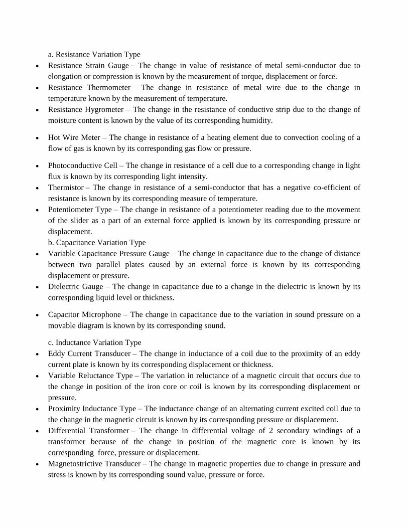
a. Resistance Variation Type
Resistance Strain Gauge – The change in value of resistance of metal semi-conductor due to
elongation or compression is known by the measurement of torque, displacement or force.
Resistance Thermometer – The change in resistance of metal wire due to the change in
temperature known by the measurement of temperature.
Resistance Hygrometer – The change in the resistance of conductive strip due to the change of
moisture content is known by the value of its corresponding humidity.
Hot Wire Meter – The change in resistance of a heating element due to convection cooling of a
flow of gas is known by its corresponding gas flow or pressure.
Photoconductive Cell – The change in resistance of a cell due to a corresponding change in light
flux is known by its corresponding light intensity.
Thermistor – The change in resistance of a semi-conductor that has a negative co-efficient of
resistance is known by its corresponding measure of temperature.
Potentiometer Type – The change in resistance of a potentiometer reading due to the movement
of the slider as a part of an external force applied is known by its corresponding pressure or
displacement.
b. Capacitance Variation Type
Variable Capacitance Pressure Gauge – The change in capacitance due to the change of distance
between two parallel plates caused by an external force is known by its corresponding
displacement or pressure.
Dielectric Gauge – The change in capacitance due to a change in the dielectric is known by its
corresponding liquid level or thickness.
Capacitor Microphone – The change in capacitance due to the variation in sound pressure on a
movable diagram is known by its corresponding sound.
c. Inductance Variation Type
Eddy Current Transducer – The change in inductance of a coil due to the proximity of an eddy
current plate is known by its corresponding displacement or thickness.
Variable Reluctance Type – The variation in reluctance of a magnetic circuit that occurs due to
the change in position of the iron core or coil is known by its corresponding displacement or
pressure.
Proximity Inductance Type – The inductance change of an alternating current excited coil due to
the change in the magnetic circuit is known by its corresponding pressure or displacement.
Differential Transformer – The change in differential voltage of 2 secondary windings of a
transformer because of the change in position of the magnetic core is known by its
corresponding force, pressure or displacement.
Magnetostrictive Transducer – The change in magnetic properties due to change in pressure and
stress is known by its corresponding sound value, pressure or force.

d. Voltage and Current Type
Photo-emissive Cell – Electron emission due to light incidence on photo-emissive surface is
known by its corresponding light flux value.
Hall Effect – The voltage generated due to magnetic flux across a semi-conductor plate with a
movement of current through it is known by its corresponding value of magnetic flux or current.
Ionisation Chamber – The electron flow variation due to the ionisation of gas caused by radio-
active radiation is known by its corresponding radiation value.
2. Active Type
Photo-voltaic Cell – The voltage change that occurs across the p-n junction due to light radiation
is known by its corresponding solar cell value or light intensity.
Thermopile – The voltage change developed across a junction of two dissimilar metals is known
by its corresponding value of temperature, heat or flow.
Piezoelectric Type – When an external force is applied on to a quartz crystal, there will be a
change in the voltage generated across the surface. This change is measured by its corresponding
value of sound or vibration.
Moving Coil Type – The change in voltage generated in a magnetic field can be measured using
its corresponding value of vibration or velocity.


THERMISTOR
• Thermistor is a contraction of a term “thermal resistor”.
• Thermistor are temperature dependent resistors. They are made of semiconductor
material which have negative temperature coefficient of resistivity i.e. their resistance
decreases with increase of temperature.
• Thermistor are widely used in application which involve measurement in the range of 0-
60º Thermistor are composed of sintered mixture of metallic oxides such as magnese,
nickle, cobalt, copper, iron and uranium
• The thermistor may be in the form of beads, rods and discs.
The thermistor provide a large change in resistance for small change in temperature. In some
cases the resistance of themistor at room temperature may decreases as much as 6% for each 1ºC
rise in temperature.

RESISTANCE THERMOMETERS
Resistance thermometers, also called resistance temperature detectors (RTDs), are sensors used
to measure temperature by correlating the resistance of the RTD element with temperature. Most
RTD elements consist of a length of fine coiled wire wrapped around a ceramic or glass core.
The element is usually quite fragile, so it is often placed inside a sheathed probe to protect it. The
RTD element is made from a pure material, typically platinum, nickel or copper. The material
has a predictable change in resistance as the temperature changes and it is this predictable change
that is used to determine temperature.
VARIABLE-INDUCTANCE TRANSDUCERS
• An inductive electromechanical transducer is a transducer which converts the physical
motion into the change in inductance.
• Inductive transducers are mainly used for displacement measurement
• The inductive transducers are of the self generating or the passive type. The self
generating inductive transducers use the basic generator principle i.e. the motion between
a conductor and magnetic field induces a voltage in the conductor.
• The variable inductance transducers work on the following principles.
• Variation in self inductance
• Variation in mutual inductance
LINEAR VARIABLE DIFFERENTIAL TRANSFORMER(LVDT)
• AN LVDT transducer comprises a coil former on to which three coils are wound.
• The primary coil is excited with an AC current, the secondary coils are wound such that
when a ferrite core is in the central linear position, an equal voltage is induced in to each
coil.
The secondary are connected in opposite so that in the central position the outputs of the
secondary cancels each other out

• The excitation is applied to the primary winding and the armature assists the induction of
current in to secondary coils.
• When the core is exactly at the center of the coil then the flux linked to both the
secondary winding will be equal. Due to equal flux linkage the secondary induced
voltages (eo1 & eo2) are equal but they have opposite polarities. Output voltage eo is
therefore zero. This position is called “null position”
PIEZO ELECTRIC TRANSDUCER
• A piezoelectric transducer is a device that transforms one type of energy to another by
taking advantage of the piezoelectric properties of certain crystals or other materials.
When a piezoelectric material is subjected to stress or force, it generates an electrical
potential or voltage proportional to the magnitude of the force. This makes this type of
transducer ideal as a converter of mechanical energy or force into electric potential.
• The high sensitivity of piezoelectric transducers makes them useful in microphones,
where they convert sound pressure into electric voltage, in precision balances, in
accelerometers and motion detectors, and as generators and detectors of ultrasound. They
are also used in non-destructive testing, in the generation of high voltages, and in many
other applications requiring the precise sensing of motion or force.
• The piezoelectric effect also works in reverse, in that a voltage applied to a piezoelectric
material will cause that material to bend, stretch, or otherwise deform. This deformation
is usually very slight and proportional to the voltage applied, and so the reverse effect
offers a method of precision movement on the micro scale. A transducer may, therefore,
be used as an actuator for the exact adjustment of fine optical instruments, lasers, and
atomic force microscopes.
