united gulf gate co. - amazon web services · 2018-05-22 · note: this test report is prepared for...
TRANSCRIPT

Note: This test report is prepared for the customer shown above and for the device described herein. It may not be duplicated or used in part without prior written consent from Bay Area Compliance Laboratories Corp. (Dongguan).
EN 55032:2015 EN 55035:2017
EN 61000-3-2:2014 EN 61000-3-3:2013
TEST REPORT For
United GULF GATE Co.
Aladel Tower,F21,Fahad Al Salem St., State of KUWAIT
Model: XT-10P
Report Type:
Amended Report
Product Type:
IP Video Intercom
Report Number: RXM180306052-01A1
Report Date: 2018-05-11
Reviewed By: Jerry Zhang EMC Manager
Test Laboratory:
Bay Area Compliance Laboratories Corp. (Dongguan) No.69 Pulongcun, Puxinhu Industry Area, Tangxia, Dongguan, Guangdong, China Tel: +86-769-86858888 Fax: +86-769-86858891 www.baclcorp.com.cn

Bay Area Compliance Laboratories Corp. (Dongguan) Report No.: RXM180306052-01A1
EN 55032:2015&EN 55035:2017 Page 2 of 39 EN 61000-3-2:2014&EN 61000-3-3:2013
TABLE OF CONTENTS DOCUMENT REVISION HISTORY ......................................................................................................................... 3
GENERAL INFORMATION ...................................................................................................................................... 4 PRODUCT DESCRIPTION FOR EQUIPMENT UNDER TEST (EUT) ................................................................... 4 OBJECTIVE ............................................................................................................................................................... 4 TEST METHODOLOGY ........................................................................................................................................... 4
SYSTEM TEST CONFIGURATION ......................................................................................................................... 5 DESCRIPTION OF TEST CONFIGURATION ......................................................................................................... 5 EQUIPMENT MODIFICATIONS ............................................................................................................................. 5 EUT EXERCISE SOFTWARE .................................................................................................................................. 5 BLOCK DIAGRAM OF TEST SETUP ...................................................................................................................... 5 SUPPORT EQUIPMENT LIST AND DETAILS ....................................................................................................... 7 SUPPORT CABLE LIST AND DETAILS ................................................................................................................. 7 TEST EQUIPMENT LIST .......................................................................................................................................... 8 ENVIRONMENTAL CONDITIONS ......................................................................................................................... 8
SUMMARY OF TEST RESULTS .............................................................................................................................. 9
2 – RADIATED EMISSIONS .................................................................................................................................... 10 MEASUREMENT UNCERTAINTY ....................................................................................................................... 10 TEST SYSTEM SETUP ........................................................................................................................................... 10 EMI TEST RECEIVER SETUP ............................................................................................................................... 11 TEST PROCEDURE ................................................................................................................................................ 11 CORRECTED AMPLITUDE & MARGIN CALCULATION ................................................................................. 12 TEST DATA ............................................................................................................................................................. 13
3 – ELECTROSTATIC DISCHARGES IEC 61000-4-2 ......................................................................................... 21 MEASUREMENT UNCERTAINTY ....................................................................................................................... 21 TEST SYSTEM SETUP ........................................................................................................................................... 21 TEST STANDARD .................................................................................................................................................. 21 TEST PROCEDURE ................................................................................................................................................ 22 TEST DATA ............................................................................................................................................................. 23
4 – CONTINUOUS RADIATED DISTURBANCES IEC 61000-4-3 ...................................................................... 26 MEASUREMENT UNCERTAINTY ....................................................................................................................... 26 TEST SYSTEM SETUP ........................................................................................................................................... 26 TEST STANDARD .................................................................................................................................................. 27 TEST LEVEL ........................................................................................................................................................... 27 TEST PROCEDURE ................................................................................................................................................ 27 TEST DATA ............................................................................................................................................................. 28
EXHIBIT A – EUT PHOTOGRAPHS...................................................................................................................... 32
EXHIBIT B – TEST SETUP PHOTOGRAPHS ...................................................................................................... 35
BELOW IS THE ORIGINAL REPORT .................................................................................................................. 39

Bay Area Compliance Laboratories Corp. (Dongguan) Report No.: RXM180306052-01A1
EN 55032:2015&EN 55035:2017 Page 3 of 39 EN 61000-3-2:2014&EN 61000-3-3:2013
DOCUMENT REVISION HISTORY
Note: This is the amended report application basing on the original report. The differences between them as following: 1) Changed the applicant to : United GULF GATE Co. (Address: Aladel Tower,F21,Fahad Al Salem St., State
of KUWAIT). 2) Changed the product name to: IP Video Intercom. 3) Changed the model name to: XT-10P. 4) Changed the trade name to: Xontel. 5) For the appearance, changed the silk-screen of trade name and the label. The changes between the original device and the current one are stated and guaranteed by the applicant, the differences between them will not affect the test results. We will keep the test results, test photos but update the related EUT photos.
Revision Number Report Number Description of Revision Date of Revision
0 RXM180205051-01 Original Report 2018-03-14
1 RXM180306052-01A1 Amended Report 2018-05-11

Bay Area Compliance Laboratories Corp. (Dongguan) Report No.: RXM180306052-01A1
EN 55032:2015&EN 55035:2017 Page 4 of 39 EN 61000-3-2:2014&EN 61000-3-3:2013
GENERAL INFORMATION Product Description for Equipment under Test (EUT)
EUT Name: IP Video Intercom EUT Model: XT-10P
Rated Input Voltage: DC 12V or PoE External Dimension: 102mm (L)*161.5mm (W)*38mm (H)
Serial Number: 180306052 EUT Received Date: 2018.04.27
Objective This report is prepared on behalf of United GULF GATE Co. in accordance with EN 55032:2015 Electromagnetic compatibility of multimedia equipment — Emission Requirements; EN 55035:2017 Information technology equipment — Immunity characteristics — Limits and methods of measurement; EN 61000-3-2:2014 Electromagnetic compatibility (EMC) – Part 3-2: Limits – Limits for harmonic current emissions (equipment input current ≤ 16 A per phase); EN 61000-3-3:2013 Electromagnetic compatibility (EMC)Part 3-3: Limits – Limitation of voltage changes, voltage fluctuations and flicker in public low-voltage supply systems, for equipment with rated current ≤ 16 A per phase and not subject to conditional connection. The objective is to determine the compliance of EUT with: EN 55032:2015 EN 55035:2017 EN 61000-3-2:2014 EN 61000-3-3:2013. Test Methodology All measurements contained in this report were conducted with EN 55032:2015 Electromagnetic compatibility of multimedia equipment — Emission Requirements; EN 55035:2017 Information technology equipment — Immunity characteristics — Limits and methods of measurement; EN 61000-3-2:2014 Electromagnetic compatibility (EMC) – Part 3-2: Limits – Limits for harmonic current emissions (equipment input current ≤ 16 A per phase); EN 61000-3-3:2013 Electromagnetic compatibility (EMC)Part 3-3: Limits – Limitation of voltage changes, voltage fluctuations and flicker in public low-voltage supply systems, for equipment with rated current ≤ 16 A per phase and not subject to conditional connection.
Bay Area Compliance Laboratories Corp. (Dongguan) Report No.: RXM180306052-01A1
EN 55032:2015&EN 55035:2017 Page 5 of 39 EN 61000-3-2:2014&EN 61000-3-3:2013
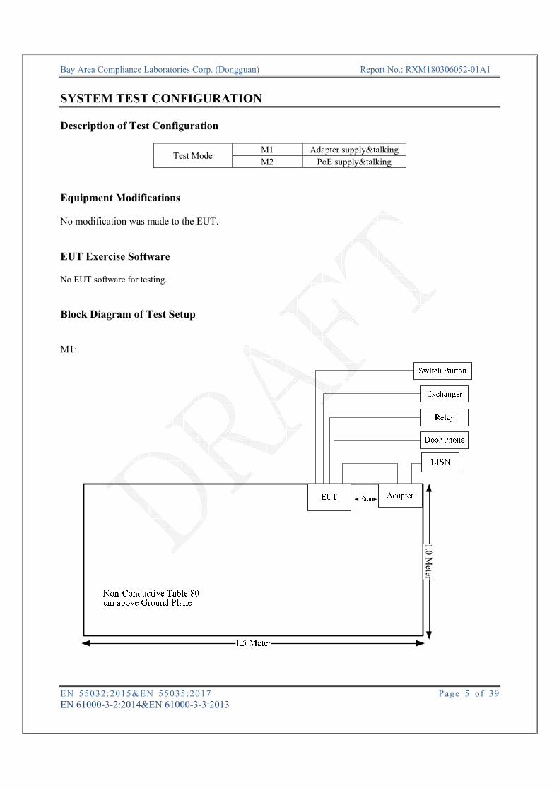
SYSTEM TEST CONFIGURATION Description of Test Configuration
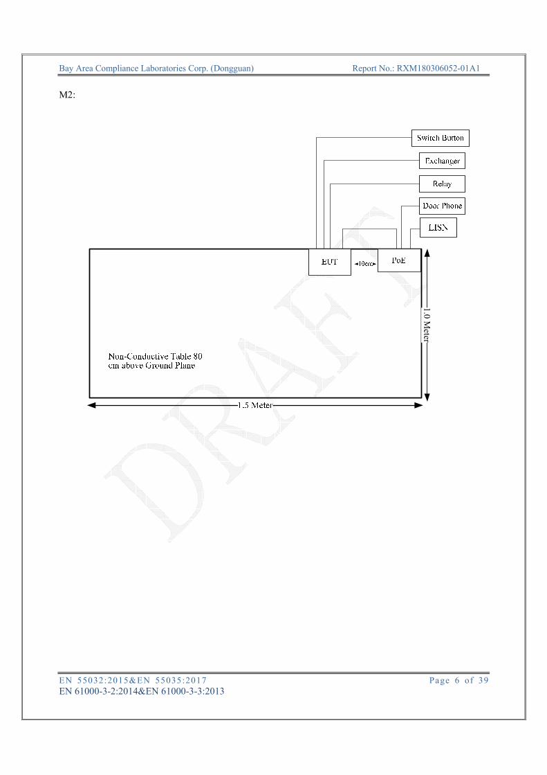
Test Mode M1 Adapter supply&talking M2 PoE supply&talking
Equipment Modifications No modification was made to the EUT. EUT Exercise Software No EUT software for testing. Block Diagram of Test Setup
M1:
1.0M
eter
Bay Area Compliance Laboratories Corp. (Dongguan) Report No.: RXM180306052-01A1
EN 55032:2015&EN 55035:2017 Page 6 of 39 EN 61000-3-2:2014&EN 61000-3-3:2013
M2:
1.0M
eter

Bay Area Compliance Laboratories Corp. (Dongguan) Report No.: RXM180306052-01A1
EN 55032:2015&EN 55035:2017 Page 7 of 39 EN 61000-3-2:2014&EN 61000-3-3:2013
Support Equipment List and Details
Support Cable List and Details
Cable Description Shielding
Type Ferrite Core Length (m)
From To
RJ45 Cable No No 5 RJ45 Port of EUT Door Phone
Signal Cable No No 5 Door Port of EUT Switch Button
Signal Cable No No 5 RS485 Port of EUT Exchanger
Signal Cable No No 5 Relay Port of EUT Relay
Power Cable No No 1.4 Power Port of EUT Adapter
RJ45 Cable No No 1 RJ45 Port of EUT PoE
RJ45 Cable No No 5 RJ45 Port of PoE Door Phone
Manufacturer Description Model Serial Number
TOTOLINK PoE G0545-480-050-POE100 N/A TP-LINK Exchanger TL-SF1008P 114A297001782 Schneider Relay RXM2LB2BD N/A AKUVOX Door Phone C313 N/A
Gouldin Switch Button N/A N/A CWT Adapter 2ABB018F N/A

Bay Area Compliance Laboratories Corp. (Dongguan) Report No.: RXM180306052-01A1
EN 55032:2015&EN 55035:2017 Page 8 of 39 EN 61000-3-2:2014&EN 61000-3-3:2013
Test Equipment List
Manufacturer Description Model Serial Number Calibration Date
Calibration Due Date
Sunol Sciences Antenna JB3 A060611-1 2017-11-10 2020-11-10R&S EMI Test Receiver ESCI 100224 2017-12-11 2018-12-11HP Amplifier 8447D 2727A05902 2017-09-05 2018-09-05N/A Coaxial Cable C-NJNJ-50 C-0400-01 2017-09-05 2018-09-05N/A Coaxial Cable C-NJNJ-50 C-0075-01 2017-09-05 2018-09-05N/A Coaxial Cable C-NJNJ-50 C-1000-01 2017-09-05 2018-09-05
ETS-Lindgren Horn Antenna 3115 000 527 35 2016-01-05 2019-01-04Agilent Spectrum Analyzer E4440A SG43360054 2018-01-04 2019-01-04
N/A Coaxial Cable C-SJSJ-50 C-0800-01 2017-09-05 2018-09-05MITEQ Amplifier AFS42-00101800-25-S-42 2001271 2017-09-05 2018-09-05Farad Test Software EZ-EMC V1.1.4.2 N/A N/A HP Signal Generator 8665B 3438a00584 2017-07-18 2018-07-18
Sunol Sciences Antenna JB3 A060611-2 2017-08-25 2020-08-25AR Power Amplifier 100W1000M1 13410 N/A N/A AR Power Amplifier 60S1G6 348711 N/A N/A
SCHAFFNER ESD Tester NSG435 005 101 2017-07-10 2018-07-10
* Statement of Traceability: Bay Area Compliance Laboratories Corp. (Dongguan) attests that all calibrations have been performed, traceable to National Primary Standards and International System of Units (SI). Environmental Conditions
Temperature: 25.1~25.9 oC
Relative Humidity: 49~59%*
ATM Pressure: 100.7~101kPa
Tester: Redick Zhang
Test Date: 2018.05.08~2018.05.09
Note: *The relative humidity of ESD test environment is 53%.

Bay Area Compliance Laboratories Corp. (Dongguan) Report No.: RXM180306052-01A1
EN 55032:2015&EN 55035:2017 Page 9 of 39 EN 61000-3-2:2014&EN 61000-3-3:2013
SUMMARY OF TEST RESULTS
SN Rule and Clause Descrption of Test Test Result
1 EN 55032 Clause A.3 Conducted emissions Compliance*
2 EN 55032 Clause A.2 Radiated emissions Compliance
3 EN 55035 Clause 4.2.1 Electrostatic discharges IEC 61000-4-2 Compliance
4 EN 55035 Clause 4.2.2.2
Continuous radiated disturbances IEC 61000-4-3 Compliance
5 EN 55035 Clause 4.2.2.3
Continuous conducted disturbances IEC 61000-4-6 Compliance*
6 EN 55035 Clause 4.2.3
Power frequency magnetic fields IEC 61000-4-8 Compliance*
7 EN 55035 Clause 4.2.4 Electrical fast transients/burst IEC 61000-4-4 Compliance*
8 EN 55035 Clause 4.2.5 Surges IEC 61000-4-5 Compliance*
9 EN 55035 Clause 4.2.6
Voltage dips and short interruptions IEC 61000-4-11 Compliance*
10 EN 61000-3-2 Harmonic current emissions Not applicable* 11 EN 61000-3-3 Voltage fluctuations and flicker Compliance* Note: Not applicable*: EUT power is less than 75w. Compliance*:Please refer to the report No.RDG180205051-021

Bay Area Compliance Laboratories Corp. (Dongguan) Report No.: RXM180306052-01A1
EN 55032:2015&EN 55035:2017 Page 10 of 39 EN 61000-3-2:2014&EN 61000-3-3:2013
2 – RADIATED EMISSIONS Measurement Uncertainty Compliance or non- compliance with a disturbance limit shall be determined in the following manner: If Ulab is less than or equal to Ucispr of Table 1, then: –compliance is deemed to occur if no measured disturbance level exceeds the disturbance limit; –non - compliance is deemed to occur if any measured disturbance level exceeds the disturbance limit. If Ulab is greater than Ucispr of Table 1, then: –compliance is deemed to occur if no measured disturbance level, increased by (Ulab − Ucispr), exceeds the disturbance limit; –non - compliance is deemed to occur if any measured disturbance level, increased by (Ulab − Ucispr), exceeds the disturbance limit. Based on CISPR 16-4-2: 2011, measurement uncertainty of radiated emission at a distance of 10m at Bay Area Compliance Laboratories Corp. (Dongguan) is:30M~200MHz: 4.55 dB for Horizontal, 4.57 dB for Vertical; 200M~1GHz: 4.66 dB for Horizontal, 4.56 dB for Vertical; measurement uncertainty of radiated emission at a distance of 3m at Bay Area Compliance Laboratories Corp. (Dongguan) is:30M~200MHz: 4.58 dB for Horizontal, 4.59 dB for Vertical; 200M~1GHz: 4.83 dB for Horizontal, 5.85 dB for Vertical 1G~6GHz: 4.45 dB, 6G~18GHz: 5.23 dB.
Table 1 – Values of Ucispr
Measurement Ucispr
Radiated disturbance (electric field strength at an OATS or in a SAC) (30 MHz to 1000 MHz) Radiated disturbance (electric field strength in a FAR) (1 GHz to 6 GHz) Radiated disturbance (electric field strength in a FAR) (6 GHz to 18 GHz)
6.3 dB5.2 dB5.5 dB
Test System Setup Below 1GHz:

Bay Area Compliance Laboratories Corp. (Dongguan) Report No.: RXM180306052-01A1
EN 55032:2015&EN 55035:2017 Page 11 of 39 EN 61000-3-2:2014&EN 61000-3-3:2013
Above 1GHz:
The radiated emission tests below 1GHz were performed in 10 meters, above 1GHz were performed in the 3 meters, using the setup accordance with the CISPR 16-1-1:2010+A1:2010, CISPR 16-1-4:2010, CISPR 16-2-3:2010. The specification used was EN 55032 Class B limits. The external I/O cables were draped along the test table and formed a bundle 30 to 40 cm long in the middle. The spacing between the peripherals was 10 cm. EMI Test Receiver Setup The system was investigated from 30 MHz to 6 GHz. During the radiated emission test, the EMI test receiver was set with the following configurations:
Frequency Range RBW Video B/W IF B/W Detector
30 MHz – 1000 MHz 120 kHz 300 kHz 120 kHz QP
Above 1 GHz 1MHz 3 MHz / Peak 1MHz 10Hz / Peak
Test Procedure During the radiated emissions, maximizing procedure was performed on the highest emissions to ensure that the EUT complied with all installation combinations.

Bay Area Compliance Laboratories Corp. (Dongguan) Report No.: RXM180306052-01A1
EN 55032:2015&EN 55035:2017 Page 12 of 39 EN 61000-3-2:2014&EN 61000-3-3:2013
Corrected Amplitude & Margin Calculation The basic equation is as follows: Result = Meter Reading+ Corrected Note: Corrected = Antenna Factor + Cable Loss - Amplifier Gain or Corrected = Antenna Factor + Cable Loss + Insertion loss of attenuator - Amplifier Gain The “Margin” column of the following data tables indicates the degree of compliance with the applicable limit. For example, a margin of 7dB means the emission is 7dB below the limit for Class B. The equation for margin calculation is as follows:
Margin = Limit – Result

Bay Area Compliance Laboratories Corp. (Dongguan) Report No.: RXM180306052-01A1
EN 55032:2015&EN 55035:2017 Page 13 of 39 EN 61000-3-2:2014&EN 61000-3-3:2013
Test Data Please refer to following table and plots: Condition: EN55032 ClassB 10m Radiation Polarization: Horizontal EUT: IP Video Intercom Power: AC 230V/50Hz Model: XT-10P Distance: 10m Test Mode: M1 Note:
No. Frequency Reading Detector Corrected Result Limit Margin (MHz) (dBμV) dB/m (dBμV/m) (dBμV/m) (dB)
1 42.6100 34.52 QP -14.42 20.10 30.00 9.90 2 149.3100 27.95 QP -12.85 15.10 30.00 14.90 3 250.1900 42.86 QP -13.56 29.30 37.00 7.70 4 384.0500 26.91 QP -8.61 18.30 37.00 18.70 5 500.4500 30.11 QP -6.21 23.90 37.00 13.10 6 587.7500 26.32 QP -3.52 22.80 37.00 14.20

Bay Area Compliance Laboratories Corp. (Dongguan) Report No.: RXM180306052-01A1
EN 55032:2015&EN 55035:2017 Page 14 of 39 EN 61000-3-2:2014&EN 61000-3-3:2013
Condition: EN55032 ClassB 10m Radiation Polarization: Vertical EUT: IP Video Intercom Power: AC 230V/50Hz Model: XT-10P Distance: 10m Test Mode: M1 Note:
No. Frequency Reading Detector Corrected Result Limit Margin (MHz) (dBμV) dB/m (dBμV/m) (dBμV/m) (dB)
1 38.7300 34.05 QP -12.15 21.90 30.00 8.10 2 87.2300 41.86 QP -18.86 23.00 30.00 7.00 3 126.0300 34.01 QP -14.51 19.50 30.00 10.50 4 250.1900 46.46 QP -13.56 32.90 37.00 4.10 5 500.4500 33.41 QP -6.21 27.20 37.00 9.80 6 587.7500 27.22 QP -3.52 23.70 37.00 13.30

Bay Area Compliance Laboratories Corp. (Dongguan) Report No.: RXM180306052-01A1
EN 55032:2015&EN 55035:2017 Page 15 of 39 EN 61000-3-2:2014&EN 61000-3-3:2013
Condition: EN55032 ClassB 10m Radiation Polarization: Horizontal EUT: IP Video Intercom Power: AC 230V/50Hz Model: XT-10P Distance: 10m Test Mode: M2 Note:
No. Frequency Reading Detector Corrected Result Limit Margin (MHz) (dBμV) dB/m (dBμV/m) (dBμV/m) (dB)
1 30.9700 29.79 QP -8.39 21.40 30.00 8.60 2 45.5200 34.66 QP -16.26 18.40 30.00 11.60 3 250.1900 40.56 QP -13.56 27.00 37.00 10.00 4 500.4500 29.91 QP -6.21 23.70 37.00 13.30 5 587.7500 30.12 QP -3.52 26.60 37.00 10.40 6 815.7000 23.07 QP -0.67 22.40 37.00 14.60

Bay Area Compliance Laboratories Corp. (Dongguan) Report No.: RXM180306052-01A1
EN 55032:2015&EN 55035:2017 Page 16 of 39 EN 61000-3-2:2014&EN 61000-3-3:2013
Condition: EN55032 ClassB 10m Radiation Polarization: Vertical EUT: IP Video Intercom Power: AC 230V/50Hz Model: XT-10P Distance: 10m Test Mode: M2 Note:
No. Frequency Reading Detector Corrected Result Limit Margin (MHz) (dBμV) dB/m (dBμV/m) (dBμV/m) (dB)
1 32.9100 33.44 QP -9.34 24.10 30.00 5.90 2 87.2300 41.16 QP -18.86 22.30 30.00 7.70 3 250.1900 46.66 QP -13.56 33.10 37.00 3.90 4 330.7000 31.66 QP -10.16 21.50 37.00 15.50 5 500.4500 32.91 QP -6.21 26.70 37.00 10.30 6 587.7500 30.02 QP -3.52 26.50 37.00 10.50

Bay Area Compliance Laboratories Corp. (Dongguan) Report No.: RXM180306052-01A1
EN 55032:2015&EN 55035:2017 Page 17 of 39 EN 61000-3-2:2014&EN 61000-3-3:2013
Condition: EN 55032 Class B(Peak) Polarization: Horizontal EUT: IP Video Intercom Power: AC 230V/50Hz Model: XT-10P Distance: 3m Test Mode: M1 Note:
No. Frequency Reading Detector Corrected Result Limit Margin (MHz) (dBμV) dB/m (dBμV/m) (dBμV/m) (dB)
1 1737.500 61.48 peak -8.20 53.28 70.00 16.72 2 1737.500 51.52 AVG -8.20 43.32 50.00 6.68 3 1800.000 52.16 peak -7.77 44.39 70.00 25.61 4 1800.000 42.37 AVG -7.77 34.60 50.00 15.40 5 2410.000 51.64 peak -6.48 45.16 70.00 24.84 6 2410.000 41.59 AVG -6.48 35.11 50.00 14.89

Bay Area Compliance Laboratories Corp. (Dongguan) Report No.: RXM180306052-01A1
EN 55032:2015&EN 55035:2017 Page 18 of 39 EN 61000-3-2:2014&EN 61000-3-3:2013
Condition: EN 55032 Class B(Peak) Polarization: Vertical EUT: IP Video Intercom Power: AC 230V/50Hz Model: XT-10P Distance: 3m Test Mode: M1 Note:
No. Frequency Reading Detector Corrected Result Limit Margin (MHz) (dBμV) dB/m (dBμV/m) (dBμV/m) (dB)
1 1500.000 46.67 peak -9.12 37.55 70.00 32.45 2 1500.000 36.72 AVG -9.12 27.60 50.00 22.40 3 1737.500 58.83 peak -8.20 50.63 70.00 19.37 4 1737.500 48.35 AVG -8.20 40.15 50.00 9.85 5 1922.500 55.01 peak -7.46 47.55 70.00 22.45 6 1922.500 45.26 AVG -7.46 37.80 50.00 12.20

Bay Area Compliance Laboratories Corp. (Dongguan) Report No.: RXM180306052-01A1
EN 55032:2015&EN 55035:2017 Page 19 of 39 EN 61000-3-2:2014&EN 61000-3-3:2013
Condition: EN 55032 Class B(Peak) Polarization: Horizontal EUT: IP Video Intercom Power: AC 230V/50Hz Model: XT-10P Distance: 3m Test Mode: M2 Note:
No. Frequency Reading Detector Corrected Result Limit Margin (MHz) (dBμV) dB/m (dBμV/m) (dBμV/m) (dB) 1 1737.500 48.11 peak -8.20 39.91 70.00 30.09 2 1737.500 38.33 AVG -8.20 30.13 50.00 19.87 3 2412.500 49.63 peak -6.47 43.16 70.00 26.84 4 2412.500 40.99 AVG -6.47 34.52 50.00 15.48 5 3375.000 47.23 peak -3.57 43.66 74.00 30.34 6 3375.000 38.44 AVG -3.57 34.87 54.00 19.13
Bay Area Compliance Laboratories Corp. (Dongguan) Report No.: RXM180306052-01A1
EN 55032:2015&EN 55035:2017 Page 20 of 39 EN 61000-3-2:2014&EN 61000-3-3:2013
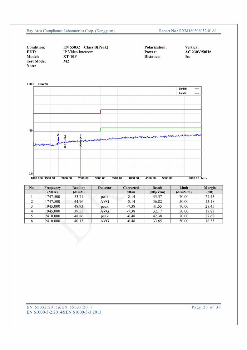
Condition: EN 55032 Class B(Peak) Polarization: Vertical EUT: IP Video Intercom Power: AC 230V/50Hz Model: XT-10P Distance: 3m Test Mode: M2 Note:
No. Frequency Reading Detector Corrected Result Limit Margin (MHz) (dBμV) dB/m (dBμV/m) (dBμV/m) (dB)
1 1747.500 53.71 peak -8.14 45.57 70.00 24.43 2 1747.500 44.96 AVG -8.14 36.82 50.00 13.18 3 1945.000 48.93 peak -7.38 41.55 70.00 28.45 4 1945.000 39.55 AVG -7.38 32.17 50.00 17.83 5 2410.000 48.86 peak -6.48 42.38 70.00 27.62 6 2410.000 40.13 AVG -6.48 33.65 50.00 16.35
Bay Area Compliance Laboratories Corp. (Dongguan) Report No.: RXM180306052-01A1
EN 55032:2015&EN 55035:2017 Page 21 of 39 EN 61000-3-2:2014&EN 61000-3-3:2013
3 – ELECTROSTATIC DISCHARGES IEC 61000-4-2 Measurement Uncertainty Ulab (measurement uncertainty of lab) and UEN (measurement uncertainty of EN 61000-4-2) please refer to the following:
Parameter UEN Ulab Rise time tr ≤15% 15%
Peak current Ip ≤7% 6.30% Current at 30 ns ≤7% 6.30% Current at 60 ns ≤7% 6.30%
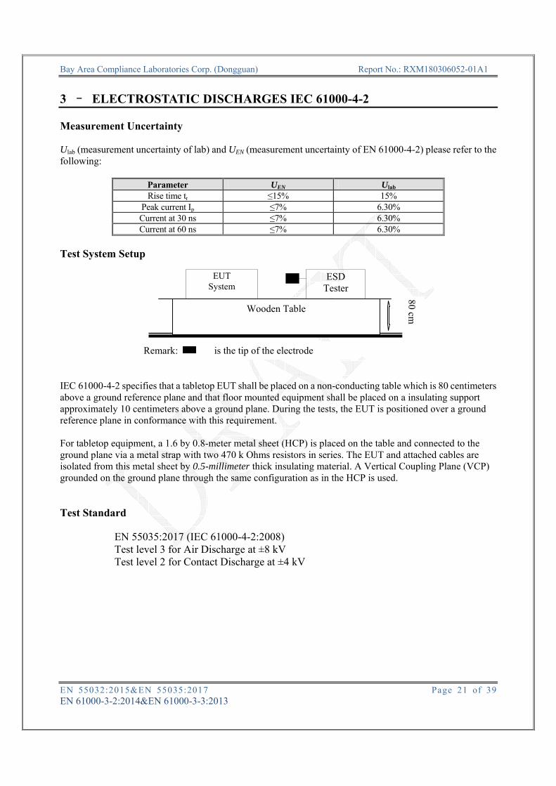
Test System Setup IEC 61000-4-2 specifies that a tabletop EUT shall be placed on a non-conducting table which is 80 centimeters above a ground reference plane and that floor mounted equipment shall be placed on a insulating support approximately 10 centimeters above a ground plane. During the tests, the EUT is positioned over a ground reference plane in conformance with this requirement. For tabletop equipment, a 1.6 by 0.8-meter metal sheet (HCP) is placed on the table and connected to the ground plane via a metal strap with two 470 k Ohms resistors in series. The EUT and attached cables are isolated from this metal sheet by 0.5-millimeter thick insulating material. A Vertical Coupling Plane (VCP) grounded on the ground plane through the same configuration as in the HCP is used. Test Standard
EN 55035:2017 (IEC 61000-4-2:2008) Test level 3 for Air Discharge at ±8 kV Test level 2 for Contact Discharge at ±4 kV
EUT System
ESD Tester
Wooden Table
Remark: is the tip of the electrode
80 cm

Bay Area Compliance Laboratories Corp. (Dongguan) Report No.: RXM180306052-01A1
EN 55032:2015&EN 55035:2017 Page 22 of 39 EN 61000-3-2:2014&EN 61000-3-3:2013
Test Level
Level Test Voltage Contact Discharge (±kV)
Test Voltage Air Discharge (±kV)
1. 2 2 2. 4 4 3. 6 8 4. 8 15 X. Special Special
Performance criteria: B
Test Procedure
Air Discharge:
This test is done on a non-conductive surface. The round discharge tip of the discharge electrode shall be approached as fast as possible to touch the EUT. After each discharge, the discharge electrode shall be removed from the EUT. The generator is then re-triggered for a new single discharge and repeated 10 times for each pre-selected test point. This procedure shall be repeated until all the air discharge completed.
Contact Discharge:
All the procedure shall be same as Section 8.3.1 of IEC 61000-4-2, except that the tip of the discharge electrode shall touch the EUT before the discharge switch is operated.
Indirect discharge for horizontal coupling plane:
At least 50 single discharges shall be applied to the horizontal coupling plane, at points on each side of the EUT. The discharge electrode positions vertically at a distance of 0.1 m from the EUT and with the discharge electrode touching the coupling plane.
Indirect discharge for vertical coupling plane:
At least 50 single discharges shall be applied to the center of one vertical edge of the coupling plane. The coupling plane, of dimensions 0.5m × 0.5m, is placed parallel to, and positioned at a distance of 0.1m from the EUT. Discharges shall be applied to the coupling plane, with this plane in sufficient different positions that the four faces of the EUT are completely illuminated.

Bay Area Compliance Laboratories Corp. (Dongguan) Report No.: RXM180306052-01A1
EN 55032:2015&EN 55035:2017 Page 23 of 39 EN 61000-3-2:2014&EN 61000-3-3:2013
Test Data Please refer to following tables: Test Mode: M1,M2 Note: Table 1: Electrostatic Discharge Immunity (Air Discharge)
Test Points Location Test Levels -2 kV +2 kV -4 kV +4 kV -8 kV +8 kV -15 kV +15 kV
Plastic Shell A A A A A A / / Port A A A A A A / / Seam A A A A A A / / Camera A A A A A A / /
Table 2: Electrostatic Discharge Immunity (Direct Contact)
Test Points Location Test Levels -2 kV +2 kV -4 kV +4 kV -6 kV +6 kV -8 kV +8 kV
Screw A A A A Button A A A A Metal Shell A A A A / / / / RJ45 Port A A A A / / / /
Table 3: Electrostatic Discharge Immunity (Indirect Contact HCP)
Test Points Location Test Levels -2 kV +2 kV -4 kV +4 kV -6 kV +6 kV -8 kV +8 kV
Front Side A A A A / / / / Back Side A A A A / / / / Left Side A A A A / / / / Right Side A A A A / / / /
Table 4: Electrostatic Discharge Immunity (Indirect Contact VCP)
Test Points Location Test Levels -2 kV +2 kV -4 kV +4 kV -6 kV +6 kV -8 kV +8 kV
Front Side A A A A / / / / Back Side A A A A / / / / Left Side A A A A / / / / Right Side A A A A / / / /
Bay Area Compliance Laboratories Corp. (Dongguan) Report No.: RXM180306052-01A1
EN 55032:2015&EN 55035:2017 Page 24 of 39 EN 61000-3-2:2014&EN 61000-3-3:2013
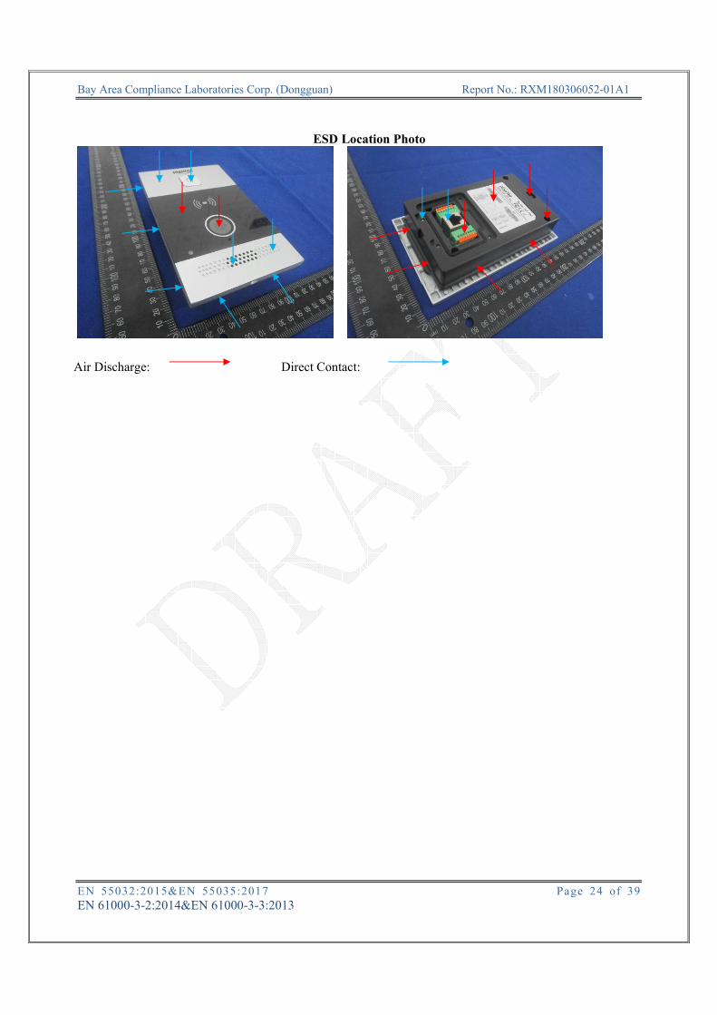
ESD Location Photo
Air Discharge: Direct Contact:
Bay Area Compliance Laboratories Corp. (Dongguan) Report No.: RXM180306052-01A1
EN 55032:2015&EN 55035:2017 Page 25 of 39 EN 61000-3-2:2014&EN 61000-3-3:2013
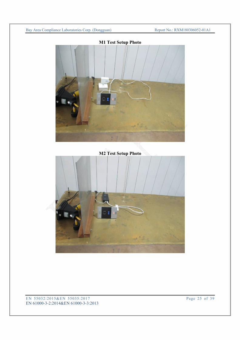
M1 Test Setup Photo
M2 Test Setup Photo

Bay Area Compliance Laboratories Corp. (Dongguan) Report No.: RXM180306052-01A1
EN 55032:2015&EN 55035:2017 Page 26 of 39 EN 61000-3-2:2014&EN 61000-3-3:2013
4 – CONTINUOUS RADIATED DISTURBANCES IEC 61000-4-3 Measurement Uncertainty Ulab (measurement uncertainty of lab) and UEN (measurement uncertainty of EN 61000-4-3) please refer to the following:
Parameter UEN Ulab Calibration process 1.88 dB 1.88 dB
Level setting 2.19 dB 2.19 dB Test System Setup Wooden table
Note: d=3m(below 1G)/1m(above 1G);
d EUT
System
80 cm
Anechoic Chamber
Power Amplifier
Signal Generator
Wooden table
Bay Area Compliance Laboratories Corp. (Dongguan) Report No.: RXM180306052-01A1
EN 55032:2015&EN 55035:2017 Page 27 of 39 EN 61000-3-2:2014&EN 61000-3-3:2013
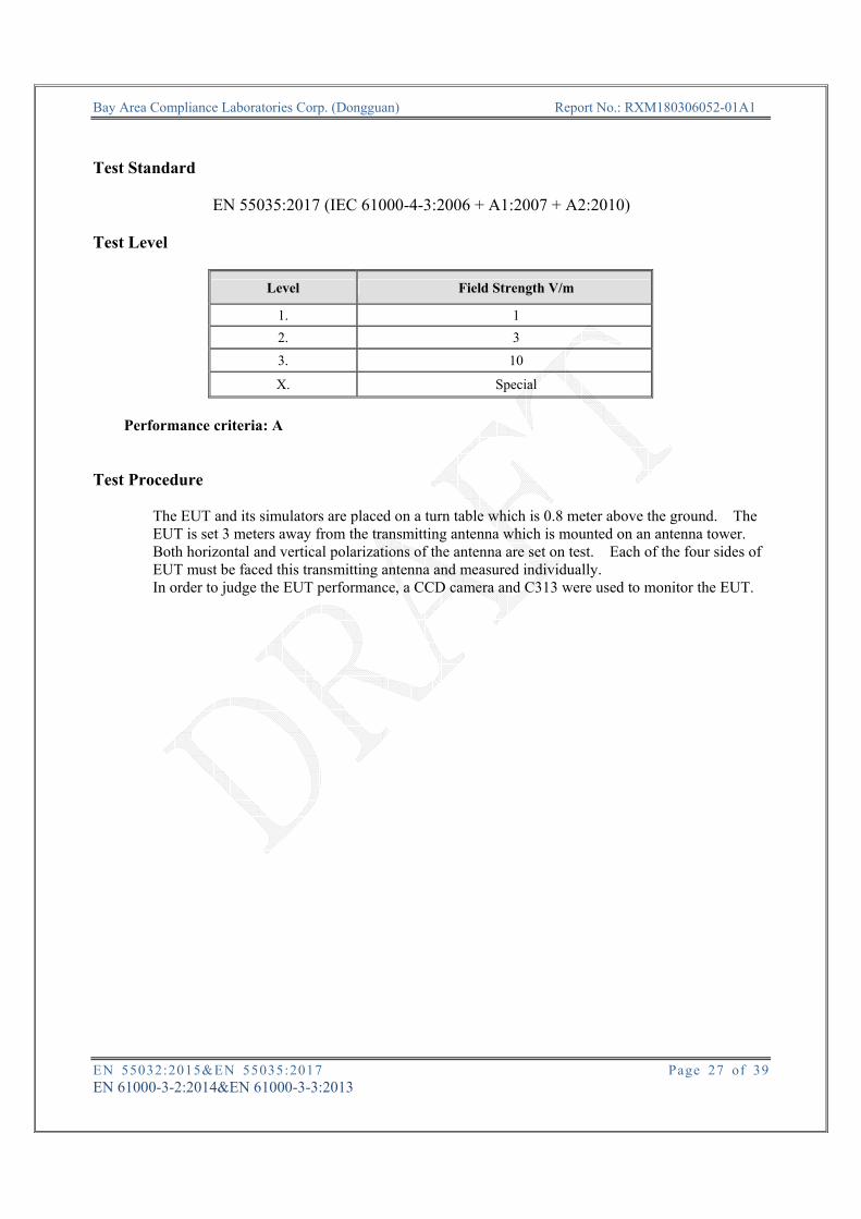
Test Standard
EN 55035:2017 (IEC 61000-4-3:2006 + A1:2007 + A2:2010) Test Level
Level Field Strength V/m
1. 1 2. 3 3. 10
X. Special
Performance criteria: A
Test Procedure
The EUT and its simulators are placed on a turn table which is 0.8 meter above the ground. The EUT is set 3 meters away from the transmitting antenna which is mounted on an antenna tower. Both horizontal and vertical polarizations of the antenna are set on test. Each of the four sides of EUT must be faced this transmitting antenna and measured individually. In order to judge the EUT performance, a CCD camera and C313 were used to monitor the EUT.
Bay Area Compliance Laboratories Corp. (Dongguan) Report No.: RXM180306052-01A1
EN 55032:2015&EN 55035:2017 Page 28 of 39 EN 61000-3-2:2014&EN 61000-3-3:2013
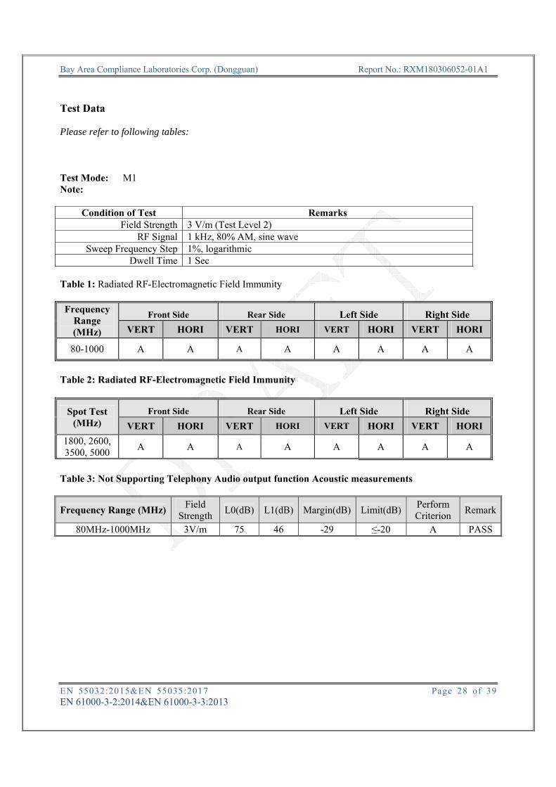
Test Data Please refer to following tables: Test Mode: M1 Note:
Condition of Test Remarks Field Strength 3 V/m (Test Level 2)
RF Signal 1 kHz, 80% AM, sine wave Sweep Frequency Step 1%, logarithmic
Dwell Time 1 Sec Table 1: Radiated RF-Electromagnetic Field Immunity Frequency
Range (MHz)
Front Side Rear Side Left Side Right Side VERT HORI VERT HORI VERT HORI VERT HORI
80-1000 A A A A A A A A
Table 2: Radiated RF-Electromagnetic Field Immunity
Spot Test (MHz)
Front Side Rear Side Left Side Right Side VERT HORI VERT HORI VERT HORI VERT HORI
1800, 2600, 3500, 5000 A A A A A A A A
Table 3: Not Supporting Telephony Audio output function Acoustic measurements
Frequency Range (MHz) Field Strength L0(dB) L1(dB) Margin(dB) Limit(dB) Perform
Criterion Remark
80MHz-1000MHz 3V/m 75 46 -29 ≤-20 A PASS

Bay Area Compliance Laboratories Corp. (Dongguan) Report No.: RXM180306052-01A1
EN 55032:2015&EN 55035:2017 Page 29 of 39 EN 61000-3-2:2014&EN 61000-3-3:2013
Table 4: Not Supporting Telephony Audio output function Acoustic measurements
Spot Test (MHz) Field Strength L0(dB) L1(dB) Margin(dB) Limit(dB) Perform
Criterion Remark
1800 3V/m 75 47 -28 ≤-20 A PASS2600 3V/m 75 48 -27 ≤-20 A PASS3500 3V/m 75 46 -29 ≤-20 A PASS5000 3V/m 75 46 -29 ≤-20 A PASS
NOTE: Electrical measurement procedures 1.Record the resulting dB(spl) level (or other appropriate unit) as the value of L0. 2.Apply the RF disturbance to the EUT and record the resulting dB(spl) level as the value of L1. 3.Calculate the interference ratio using the following formula:Acoustic Interference Ratio = L1 – L0.
M1-Test Setup Photo

Bay Area Compliance Laboratories Corp. (Dongguan) Report No.: RXM180306052-01A1
EN 55032:2015&EN 55035:2017 Page 30 of 39 EN 61000-3-2:2014&EN 61000-3-3:2013
Test Mode: M2 Note:
Condition of Test Remarks Field Strength 3 V/m (Test Level 2)
RF Signal 1 kHz, 80% AM, sine wave Sweep Frequency Step 1%, logarithmic
Dwell Time 1 Sec Table 1: Radiated RF-Electromagnetic Field Immunity Frequency
Range (MHz)
Front Side Rear Side Left Side Right Side VERT HORI VERT HORI VERT HORI VERT HORI
80-1000 A A A A A A A A
Table 2: Radiated RF-Electromagnetic Field Immunity
Spot Test (MHz)
Front Side Rear Side Left Side Right Side VERT HORI VERT HORI VERT HORI VERT HORI
1800, 2600, 3500, 5000 A A A A A A A A
Table 3: Not Supporting Telephony Audio output function Acoustic measurements
Frequency Range (MHz) Field Strength L0(dB) L1(dB) Margin(dB) Limit(dB) Perform
Criterion Remark
80MHz-1000MHz 3V/m 75 50 -25 ≤-20 A PASS
Bay Area Compliance Laboratories Corp. (Dongguan) Report No.: RXM180306052-01A1
EN 55032:2015&EN 55035:2017 Page 31 of 39 EN 61000-3-2:2014&EN 61000-3-3:2013
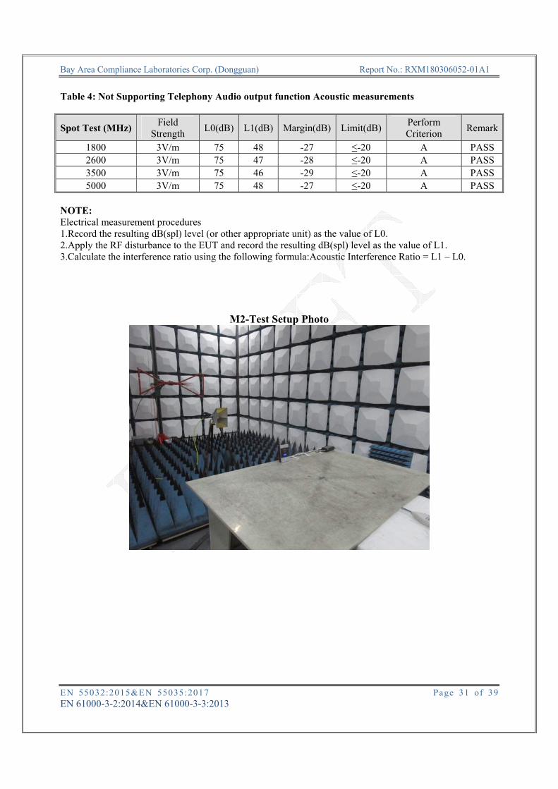
Table 4: Not Supporting Telephony Audio output function Acoustic measurements
Spot Test (MHz) Field Strength L0(dB) L1(dB) Margin(dB) Limit(dB) Perform
Criterion Remark
1800 3V/m 75 48 -27 ≤-20 A PASS2600 3V/m 75 47 -28 ≤-20 A PASS3500 3V/m 75 46 -29 ≤-20 A PASS5000 3V/m 75 48 -27 ≤-20 A PASS
NOTE: Electrical measurement procedures 1.Record the resulting dB(spl) level (or other appropriate unit) as the value of L0. 2.Apply the RF disturbance to the EUT and record the resulting dB(spl) level as the value of L1. 3.Calculate the interference ratio using the following formula:Acoustic Interference Ratio = L1 – L0.
M2-Test Setup Photo

Bay Area Compliance Laboratories Corp. (Dongguan) Report No.: RXM180306052-01A1
EN 55032:2015&EN 55035:2017 Page 32 of 39 EN 61000-3-2:2014&EN 61000-3-3:2013
EXHIBIT A – EUT PHOTOGRAPHS
EUT – All View
EUT – Bottom View

Bay Area Compliance Laboratories Corp. (Dongguan) Report No.: RXM180306052-01A1
EN 55032:2015&EN 55035:2017 Page 33 of 39 EN 61000-3-2:2014&EN 61000-3-3:2013
EUT – Side View
EUT – Label View

Bay Area Compliance Laboratories Corp. (Dongguan) Report No.: RXM180306052-01A1
EN 55032:2015&EN 55035:2017 Page 34 of 39 EN 61000-3-2:2014&EN 61000-3-3:2013
EUT – Port View

Bay Area Compliance Laboratories Corp. (Dongguan) Report No.: RXM180306052-01A1
EN 55032:2015&EN 55035:2017 Page 35 of 39 EN 61000-3-2:2014&EN 61000-3-3:2013
EXHIBIT B – TEST SETUP PHOTOGRAPHS
RE Below 1G Front-M1 View
RE Below 1G Rear-M1 View
Bay Area Compliance Laboratories Corp. (Dongguan) Report No.: RXM180306052-01A1
EN 55032:2015&EN 55035:2017 Page 36 of 39 EN 61000-3-2:2014&EN 61000-3-3:2013
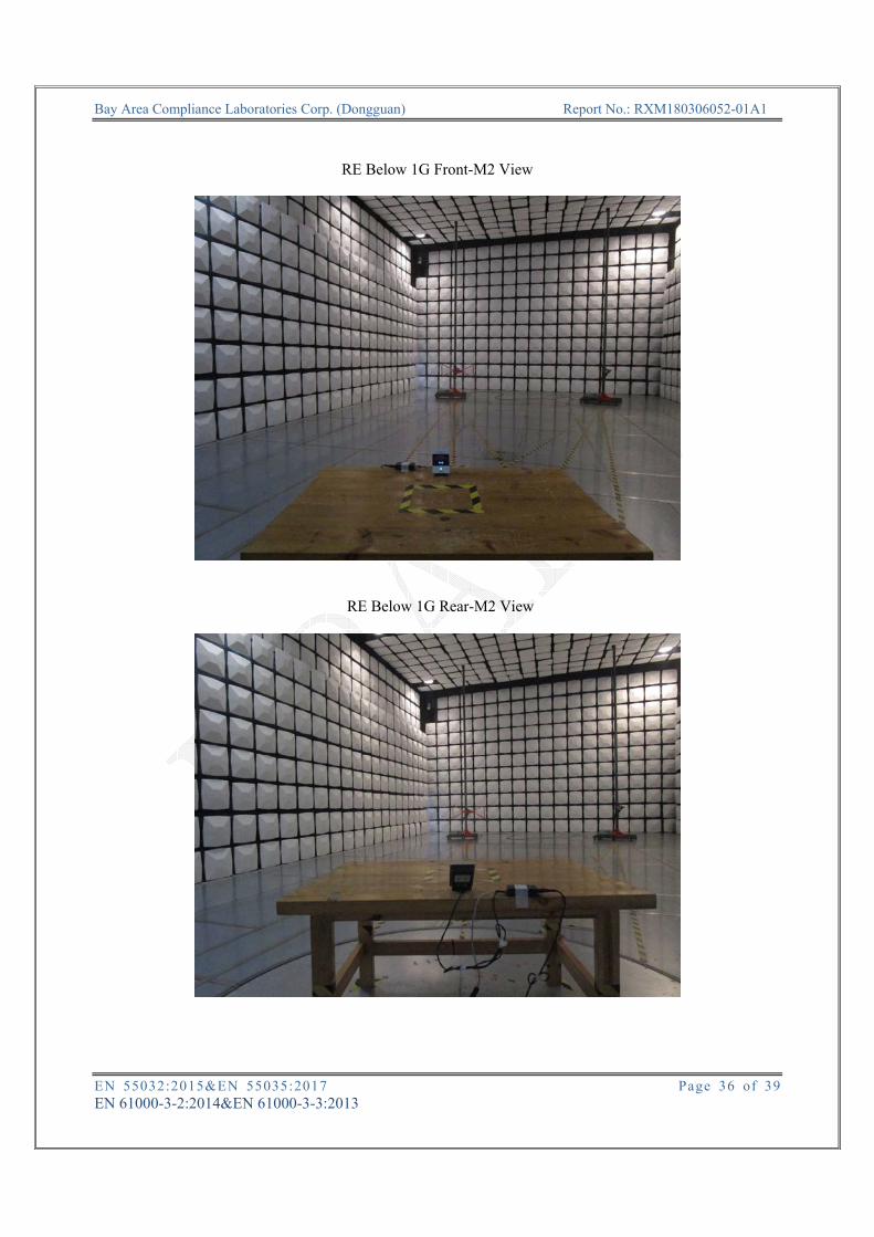
RE Below 1G Front-M2 View
RE Below 1G Rear-M2 View

Bay Area Compliance Laboratories Corp. (Dongguan) Report No.: RXM180306052-01A1
EN 55032:2015&EN 55035:2017 Page 37 of 39 EN 61000-3-2:2014&EN 61000-3-3:2013
RE Above 1G Front-M1 View
RE Above 1G Rear-M1 View

Bay Area Compliance Laboratories Corp. (Dongguan) Report No.: RXM180306052-01A1
EN 55032:2015&EN 55035:2017 Page 38 of 39 EN 61000-3-2:2014&EN 61000-3-3:2013
RE Above 1G Front-M2 View
RE Above 1G Rear-M2 View

Bay Area Compliance Laboratories Corp. (Dongguan) Report No.: RXM180306052-01A1
EN 55032:2015&EN 55035:2017 Page 39 of 39 EN 61000-3-2:2014&EN 61000-3-3:2013
BELOW IS THE ORIGINAL REPORT