united states coast guard sector new york, …
TRANSCRIPT

UNITED STATES COAST GUARD
SECTOR NEW YORK, PREVENTION DEPARTMENT
GUIDE TO PLAN SUBMITTAL
SMALL PASSENGER VESSELS INSPECTED UNDER 46 CFR SUBCHAPTER "T"
Applicability (46CFR 175.110) - Vessels of less than 100 Gross Tons that carry 150 or less passengers, or has overnight accommodations for 49 or less passengers that carry more than six
passengers for hire.
Revised Jan 2014 1

2

Revised Jan 2014 3
GUIDE TO PLAN SUBMITTAL In response to your inquiry regarding Coast Guard inspections and certification of your small passenger vessel, the applicable regulations for new or existing small passenger vessels can be found in Title 46, Code of Federal Regulations (CFR), parts 175-185, known as subchapter T. You may obtain a copy of these regulations at the U.S. Government Printing Office in Washington D. C. (202) 512-1800 or another source which carries government pubs. In addition, the Code of Federal Regulations and other pertinent Coast Guard policies can be accessed from the Internet at www.uscg.mil. The decision to build a new vessel, or convert an existing vessel, to the standards required by the U.S. Coast Guard to carry passengers is an important and difficult one that must be carefully considered. It has been our experience that many individuals who intend to buy, convert or construct a Small Passenger Vessel do not realize all that is required in obtaining a Certificate of Inspection. Consequently, many builders and new owners have had to make extensive and costly alterations to comply with the Coast Guard regulations. In many cases, such alterations could have been included in the individual's budget and could have been avoided entirely if the owner or builder had been aware of the regulations. For that reason, you should carefully prepare for the building, conversion, or alteration of your vessel -- and have your proposals reviewed by a USCG marine inspector before work begins. Prior to the initial inspection visit of your vessel by this office or the start of construction if the vessel is to be built, an application for inspection of U.S. vessel (CG-3752) must be submitted to this office. Two copies of plans listed below must also be submitted for review and approval: (a) Midship section (b) Outboard profile (c) Inboard profile (d) Arrangement of decks (e) Machinery installation (f) Electrical installation (g) Fuel tanks (h) Piping systems (i) Hull penetrations and shell connections (j) Survival craft embarkation stations (k) Lifesaving equipment locations and installation (l) Fire protection equipment installation (m) Marine sanitation device installation (n) Lines and offsets, curves of form, cross curves of stability, tank capacities Vessels carrying over 150 passengers or having overnight accommodations for more than 50 passengers are required to meet the regulations in 46 CFR 114-122, subchapter K. Plan review for these vessels will be done by the USCG Marine Safety Center (MSC); Marine Safety Center, US Coast Guard Stop 7410, 4200 Wilson Boulevard, Suite 400, Arlington, VA 20598-7410. Please visit their internet web site for information on submitting plans to that office: http://www.uscg.mil/hq/msc/PRGuidance.htm

4
Plans must be drawn to scale or dimensions indicated and submitted in duplicate. All plans should be submitted at least 3 months prior to the start of construction, or for existing vessels, 3 months before the date of initial inspection. All plans and correspondence should be submitted to this office through a single point of contact (i.e. naval architect, builder or owner). Plans submitted to this office for review that do not contain required information or in general are not needed for review will be returned without action to the submitter. In general, the vessel's hull structure must meet the standards of a recognized classification society. The classification society standards that are used are: Lloyd's Register of Shipping - All hull materials. American Bureau of Shipping - Aluminum, fiberglass and steel only. To assist you in your preparation, the enclosed package is designed as a guide for submitting plans to the Coast Guard, and to explain the process involved in obtaining a Coast Guard Certificate of Inspection. After reviewing the enclosed material and applicable Coast Guard regulations, please feel free to contact this office if additional clarification is needed, or for any questions you may have.
Commander U.S. Coast Guard New York Prevention Department/Plan Review Officer 212 Coast Guard Drive Staten Island, NY 10305 (718)-354-4283
The completeness and clarity of the information you submit for review directly affects the time it will take to go through the plan review process. Although professional drawings are not required for plan submission, a clean and legible plan detailing all required information will greatly reduce the amount of time required for review. Plans showing specific details or other systems are sometimes requested by the plan review officer to clarify confusing or complicated systems. The order given above is suggested as the order for submission of plans when a vessel first comes under consideration for certification. If the vessel under consideration fails to meet the standards of each section after being reviewed in this order, it may not be possible to continue on to other systems. Therefore, it is preferable to submit all plans in one package so that information on one plan may be used in the evaluation of other plans.

Revised Jan 2014 5
Full particulars concerning details of materials, manufacturing processes and equipment to be used in the vessel are to be submitted. It is often helpful to attach or include a "Bill of Materials" for each plan. Exact requirements for Bills of Materials are covered in detail under sections regarding each plan. Any calculations performed to determine scantlings, dimensions, sizes, etc. should be submitted with the plan. These aid in the plan review process and will be reviewed along with the plan. Any vessel which is undergoing any significant modifications (other than replacement in kind) must submit the applicable plans to the plan review officer. Failure to do so may result in the modification being removed or redone. If in doubt as to what constitutes a significant modification, contact the local OCMI for his interpretation.

6
THE STANDARDS AND WHERE TO LOOK FOR PERTINENT INFORMATION TITLE 46 CODE OF FEDERAL REGULATIONS, PARTS 166-199 Parts 175 through 185 of 46 CFR are entitled Subchapter "T", Small Passenger Vessels (hence the name "T-Boat"). This section contains most of the regulations you will need to know in regard to equipment, machinery, lifesaving equipment, and electrical installations. It also contains the regulations on Stability and Subdivision which apply to "T" boats. TITLE 33 CODE OF FEDERAL REGULATIONS, PARTS 1-199 This publication contains the Federal Regulations that pertain to navigation lights, Rules of the Road and the requirements for Marine Sanitation Devices. Many parts of this book are not applicable to Small Passenger Vessels so be sure to read the Applicability section of each part. This book is available at the same address as Title 46. The Code of Federal Regulations may be ordered at the below location or viewed on the Internet at: http://www.access.gpo.gov/nara/cfr/ AMERICAN BUREAU OF SHIPPING RULES FOR BUILDING AND CLASSIFICATION OF VESSELS The American Bureau of Shipping (ABS) is a vessel classification society which publishes standards for the evaluation of hull strength and structural adequacy. ABS standards for ship and boat construction are widely accepted and are specifically referenced in many sections of Subchapter "T". ABS rules are divided into several volumes, each dealing with a different type of construction. The most commonly used volumes are the standards for vessels constructed of steel, fiberglass or aluminum. The steel standards are further subdivided into vessels under and over 200 feet. ABS Rules are available on their web site at: http://www.eagle.org/ LLOYD'S RULES AND REGULATIONS FOR THE CLASSIFICATION OF YACHTS AND SMALL CRAFT Lloyd's is another classification society mentioned in Subchapter "T" as an acceptable standard. Lloyd's is most commonly used in evaluating the hull strength and structural adequacy of wood hull boats and is the only acceptable standard for wood boats. It is available at:

Revised Jan 2014 7
AMERICAN BOAT AND YACHTING COUNCIL SAFETY STANDARDS FOR SMALL CRAFT This manual contains a number of recommended practices that are used by the Officer in Charge, Marine Inspection (OCMI) as guidance with regard to good marine practice. The standard on Exhaust Systems (P-1) is incorporated into the Federal Regulations and vessels which comply with that standard are considered in compliance with Federal Regulations. ABYC's standards are available at http://www.abycinc.org NAVIGATION AND VESSEL INSPECTION CIRCULARS (NVIC) NVIC's are published by the Coast Guard and provide the public with Coast Guard interpretations and policies for various subjects such as Stability, Fire Protection, Lifesaving and Firefighting Equipment and Electrical Installations. NVIC's and an index to them are available on the internet at: http://www.uscg.mil/hq/g-m/nvic/

8
APPLICATION FOR INSPECTION OF U.S. VESSEL Once you have reviewed the applicable requirements and decided that you want your vessel to be certificated, you must complete form CG-3752, "APPLICATION FOR INSPECTION OF U.S. VESSEL" and return it to the Officer in Charge, Marine Inspection (OCMI) nearest to where your vessel is located. Upon receipt of your application, the plan review officer will usually be assigned to oversee the construction and initial phases of inspection. Fill out the form completely, inserting N/A where the section does not apply. Generally new vessel construction plans will be sent to MSC for review, which will take approximately 60 days. The following definitions may help: Steam Vessel: Vessel propelled by steam engines. Motor Vessel: Vessel propelled by internal combustion engine and more than 65 feet in length. Motor Boat: Vessel propelled by internal combustion engine and 65 feet or less in length. Barge: A non-self propelled vessel. Passenger Vessel: Any vessel carrying passengers for hire. No. of Passengers: Indicate the number of passengers you
wish to carry. Different requirements apply as the number of passengers increases. The Official Number (O.N.) for existing vessels will be the same as shown on the vessel's Certificate of Documentation (COD), or if state registered, the state number. For vessels under construction, the builders hull identification number will be sufficient. The Waters will be one of the following which are listed in decreasing severity: A. Oceans (a route more than 20 nautical miles offshore) B. Coastwise, not more than 20 miles offshore C. Lakes, Bays and Sounds D. Rivers Oceans and Coastwise waters are considered to be "Exposed Waters", Coastwise Not more than 20 miles OR 20 miles from a Harbor of Safe Refuge are considered "Partially Protected" and Lakes, Bays and Sounds, and Rivers are considered "Protected Waters". These definitions will become important during the review for Stability and Subdivision. The Geographical limits are usually between two easily identifiable points such as capes, towns, rivers or inlets. EXAMPLE: Coastwise: The Gulf of Mexico between Stark Point, Florida and Cape Romano, Florida, not more than 20 miles offshore, under reasonable operating conditions. Length of vessel is the overall length (LOA) measured in feet and tenths of feet. Hull material will normally be either wood, steel, aluminum, fiberglass. The inspection time and place can be arranged later after the plan review officer has completed the technical review. Several trips will be required during the construction of a new

Revised Jan 2014 9
vessel. For an existing vessel usually two trips will suffice if the applicable standards have been met. The first inspection will usually be for a credit drydocking and the second for an in the water and equipment inspection. Unless your vessel has been built under the supervision of a classification society surveyor, mark this section N/A. Do not mark this section with regard to which standard your vessel was built (i.e. ABS Rules for Shipbuilding, Lloyd's Rules, etc.). Be sure to sign the application and include a return address and a daytime telephone number.
GENERAL REQUIREMENTS All plans submitted for approval should have the following information marked on them: | VESSEL NAME:_________________________ | Official Number:_____________________ | Route:_______________________________ | Scale:_____inches = __________feet | Plan Identification:_________________ |___________________________________________ The Official Number and Route should be the same as was submitted on the Application for Inspection. The use of graph paper is highly encouraged in submitting scaled drawings for review. Scaled drawings are preferred since any dimension not listed can usually be determined by measurement. Photographs, if large enough and showing sufficient detail, may be submitted in addition to sketches and listings of measurements, dimensions and specifications. Abbreviations may be used as long as the meaning of the abbreviation is clear to the reviewing officer. In many instances, the services of a naval architect or marine surveyor will not be necessary in preparing your plans for submittal. However, all drawings should be clear, concise and of large enough scale so as to be easily legible. Plans which are of too small scale, indecipherable or overly sloppy will be returned. Plans should be submitted at least in duplicate. The Coast Guard will normally maintain one copy for our files and send the second copy to the owner stamped "Approved". If only one copy is furnished to the Coast Guard, it will remain in the vessel file, once approved.
10
INBOARD PROFILE - GENERAL The Inboard Profile is a construction profile used to show the internal structural members of the vessel. It will be used to evaluate the strength of the hull. The plan should show the following structures as a minimum: 1. The location of the collision bulkhead and load waterline. 2. The location of all watertight bulkheads. 3. The location of any vapor-tight bulkheads. 4. The keel. 5. The frames. 6. The longitudinal members in the hull. 7. The engine foundations. 8. The propeller shaft penetration(s). 9. All hatch openings and the reinforcing carlings around the openings.
10. Location of all fuel tanks and other tanks. 11. Superstructure, deckhouse, construction and details. 12. Ballast.
The following dimensions should also be shown on the inboard profile: 1. The Length Over All (LOA) - the horizontal distance between the forward-most and after-most points on the hull, not including any appurtenances (e.g., bow sprits, swim platform). 2. The Length on the Waterline (LWL) - the horizontal distance between the forward-most and after-most points on a vessel's waterline, excluding any appurtenances. 3. The scantling length which can be determined by the following equation: L = (LOA + LWL) X 0.5 4. Amidships refers to that location at the middle of the static water line. 5. Breadth (B) - The extreme breadth measured between the outer sides of the hull, excluding rubbing strakes or other projections. 6. Depth (D) - The distance measured from the bottom of the keel to the top of the upper deck or gunwale at amidships. 7. Speed (V) - The maximum speed in knots.

Revised Jan 2014 11
INBOARD PROFILE
Wood Vessels Supplementary Data
For wooden vessels, a Bill of Materials must be supplied with the Inboard (Construction) Profile either on the plan itself or on supporting worksheets. The Bill of Materials must include: 1. The species of timber used for each structural member is to be specified. 2. The timber moisture content for each member. A general statement as to the moisture content of all timbers may be made. Timbers that are to be glued or sheathed in synthetic resins are specially considered and each member should have its moisture content specified. 3. The type of preservative to be used, if any. 4. The type of glues to be used in the construction and lamination of structural members if applicable. 5. The type of metal fastenings to be used in the construction of the hull and coachwork. For vessels of unconventional form or proportion, over 100 feet long, or with a maximum speed of more than 20 knots, additional information may be required in order to evaluate the suitability of using Lloyd's Rules for scantling calculations.

12
CONSTRUCTION SECTIONS The construction sections are to show construction details at the following locations: 1. Amidships 2. At the collision bulkhead 3. At each watertight bulkhead 4. At each fume-tight bulkhead 5. In way of the deckhouse to show foundations and cabin constructions details. 6. At the engine beds. The construction sections must show details of all structural members including: 1. Type of Materials A. For wood vessels, the species of wood B. For steel or aluminum vessels, the grade of metal C. For fiberglass vessels, the type of cloth and resin. (See section on OTHER CONSIDERATIONS) 2. Scantlings - Dimensions for all members. For wood members, use true dimensions, not construction measurements. 3. Fastenings A. For wood vessels, size and materials of all nails, bolts, glues, pins, etc. B. For metal boats, the weld sizes, electrode types, weld pattern, etc. C. For fiberglass boats, overlaps, encapsulation of members, etc. The above list is not all-inclusive for all types of vessels. The plan review officer may request other information or details for a particular vessel. Other required details can be found in the sections on construction applicable to the specific type of vessel construction.

Revised Jan 2014 13
OUTBOARD PROFILE The outboard profile should show the proposed exterior view of the vessel as it will appear when completed. This view should show in solid outline the following items: 1. Hull 2. Deckhouse 3. Keel 4. Rudder(s) 5. Shaft(s) 6. Propeller(s) 7. Strut(s) 8. Deck Scuppers or Freeing Ports 9. Ventilating Cowls and Vents
10. Port Lights and Windows 11. Safety Rails and Storm Rails 12. Navigation Lights 13. Location of all Primary Lifesaving Equipment 14. Hull penetrations 15. Length of each compartment 16. Freeboard Forward, Amidships and Aft
Additionally, the plan should show the following items as dotted lines: 1. Deck(s) 2. Bulkhead(s) A. Watertight B. Collision C. Fume-tight 3. Engine(s) 4. Exhaust(s) 5. Fuel Tank(s) 6. Other Tank(s) A. Water B. MSD C. Air Receiver 7. Location of Major Auxiliary Equipment A. Generator B. MSD C. Heater 8. Means of escape from enclosed compartment(s) 9. Watertight Hatch(es) or Door(s)
10. Load Water Line 11. Ladders
14
OUTBOARD PROFILE (Continued)
The following information should be indicated on the Outboard Profile plan. For the sake of clarity, much of the information may be listed separately: 1. Length Over All - (LOA) - the horizontal distance between the forward-most and after-most points on the hull, not including any appurtenances (e.g., bow sprits, swim platform). 2. Length at Load Water Line - (LWL) - the horizontal distance between the forward-most and after-most points on a vessel's waterline, excluding any appurtenances. 3. The height of the upper side of the deck from the Load Water Line, measured forward, amidships and aft. 4. The heights of any coamings on doorways or access openings. 5. The height of all gunwales and safety rails from top to bottom and between each course. 6. The height of the sidelights above the gunwale and the height of the masthead light above the sidelights. 7. The length of all compartments between watertight bulkheads measured at the Load Water Line. 8. Depth and width of the rudder(s). 9. Type of propeller (right hand or left hand turning, viewed from the stern), and the pitch.
10. Depth, width, thickness and type of glazing used on all windows or portlights.
11. The location of deadlight covers and storm shutters.
12. The total area of freeing ports or scuppers.
Revised Jan 2014 15
GENERAL ARRANGEMENT (DECK) The General Arrangement plan should be a plan view (overhead) of each deck or cabin roof showing the following: 1. The arrangement of the various compartments including: A. Galley B. Lounge C. Pilothouse D. Accommodations E. Head(s) 2. Permanent fixed seating and aisles. 3. The locations of all permanently installed equipment. 4. The locations of all portable equipment installed as part of the vessel's equipment. 5. Deck hatches showing method of attachment and securing. 6. Ladders 7. Doors (include width) 8. Windows ( include all dimensions L x W x T). 9. Firefighting Equipment A. Fixed - a separate diagram of the fixed system may be required to avoid confusion with other systems and to properly identify all components. B. Portable - any portable extinguishers should be identified. Include type and size, e.g. B-II, Dry Chemical; B-III, Carbon Dioxide, etc.
10. Primary Lifesaving Equipment A. Life Floats, Buoyant Apparatus, Life Rafts B. Life Jackets - No. of adult, child, waterlights C. Ring Buoys - No. with line and with waterlights D. Emergency Position Indicating Radio Beacon (EPIRB)
11. Vents for machinery and fuel tank spaces, and enclosed compartments, including securing devices for vents.
12. Navigation Lights - Color; Limits and Arc of visibility 13. Freeing Ports or Scuppers 14. Fuel Shutoff Valves 15. Ground Tackle
A. Anchor - type, number and size B. Cable - type, length and size C. Windlass and hawse pipes.
16
MACHINERY INSTALLATION Plans for the machinery installation should show, in detail, the installation of all machinery on board the vessel. The machinery installation plans may be broken down into a Main Propulsion Machinery Plan and an Auxiliary Machinery Plan and should show all of the following specifications and dimensions: PROPULSION MACHINERY 1. Main Engines spec's including manufacturer, type design, shaft horsepower, maximum engine RPM. 2. Engine Foundations 3. Cooling systems with details of a. Cooling water pump b. Water pump capacity c. Sea chest and skin valve configuration and specification. 4. Gearbox spec's including manufacturer, type design, and RPM at crankshaft. 5. Fuel Systems 6. Exhaust System with details of: a. Exhaust manifold b. Exhaust hose/pipe and flexible connections c. Pitch of exhaust pipe d. Water injection e. Bulkhead penetrations 7. Ventilation of Engine Compartment 8. Shaft hull penetration fitting 9. Shafting (size, material)
10. Propeller(s) 11. Details of propeller brackets (width, depth, material,
boss, and fastenings) 12. Rudder and steering details (materials, dimensions, taper, bearings, torque,
pintles, coupling bolts, keys) 13. Auxiliary steering method 14. Drip pans
AUXILIARY MACHINERY - Generators, Aux. motors 1. Fuel oil system 2. Ventilation 3. Exhaust arrangements 4. Foundations 5. Drip Pans
Revised Jan 2014 17
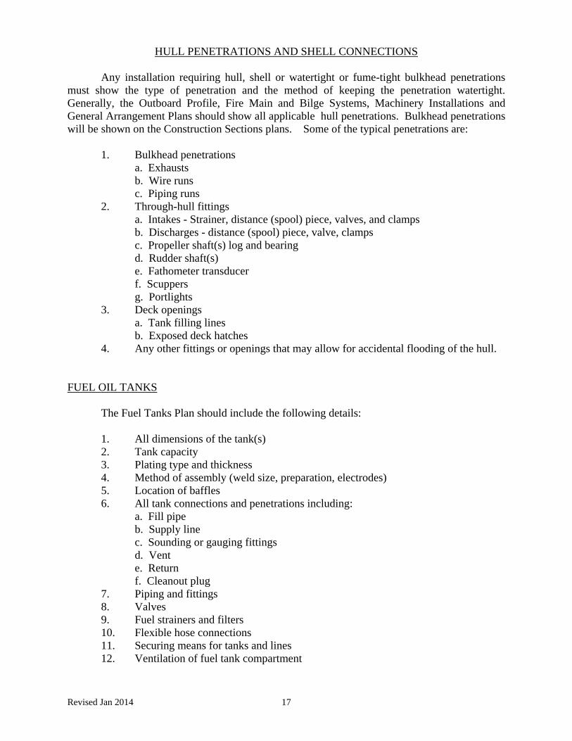
HULL PENETRATIONS AND SHELL CONNECTIONS Any installation requiring hull, shell or watertight or fume-tight bulkhead penetrations must show the type of penetration and the method of keeping the penetration watertight. Generally, the Outboard Profile, Fire Main and Bilge Systems, Machinery Installations and General Arrangement Plans should show all applicable hull penetrations. Bulkhead penetrations will be shown on the Construction Sections plans. Some of the typical penetrations are: 1. Bulkhead penetrations a. Exhausts b. Wire runs c. Piping runs 2. Through-hull fittings a. Intakes - Strainer, distance (spool) piece, valves, and clamps b. Discharges - distance (spool) piece, valve, clamps c. Propeller shaft(s) log and bearing d. Rudder shaft(s) e. Fathometer transducer f. Scuppers g. Portlights 3. Deck openings a. Tank filling lines b. Exposed deck hatches 4. Any other fittings or openings that may allow for accidental flooding of the hull. FUEL OIL TANKS The Fuel Tanks Plan should include the following details: 1. All dimensions of the tank(s) 2. Tank capacity 3. Plating type and thickness 4. Method of assembly (weld size, preparation, electrodes) 5. Location of baffles 6. All tank connections and penetrations including: a. Fill pipe b. Supply line c. Sounding or gauging fittings d. Vent e. Return f. Cleanout plug 7. Piping and fittings 8. Valves 9. Fuel strainers and filters
10. Flexible hose connections 11. Securing means for tanks and lines 12. Ventilation of fuel tank compartment

18
ELECTRICAL INSTALLATION 46 CFR 176.700 states no alterations or major repairs shall be made without the knowledge and approval of the OCMI. Proposed alterations shall be approved before work is started. The proposal may take the form of drawings, sketches, written specifications and bills of materials. Drawings are not required for repairs or replacements in kind. Compliance with this regulation is especially important for electrical systems. Many T-boat owners and operators unknowingly endanger their passengers and vessels by modifying or adding to their electrical system without approval or guidance. When electrical deficiencies are discovered during a Coast Guard inspection, the Inspector may issue a requirement to provide a drawing of the system as it presently exists. If this drawing reveals the electrical system or materials do not meet 46 CFR part 183, requirements will be issued to correct the deficiencies. This process can lead to expensive repairs and loss of revenue while the vessel is out of service, all of which could have been avoided if plans had been submitted. The first step is to obtain and review a copy of 46 CFR part 183, the T-boat electrical regulations. This step is very important because many of the regulations address items which are not part of the plan review process, i.e. specific requirements for the actual installation. If you do not review the regulations, you may be surprised when an Inspector comes to do the final installation inspection and tells you the wire nuts and spade type crimp connectors that you used are not acceptable. A bill of materials is essential information for electrical plan review. The type, manufacturer, model and rating of switches, wire, circuit breakers, enclosures, etc. should be submitted. Wire size (AWG), insulation type, temperature ratings, length of runs, or the circuit load in amps, are required for each circuit and/or conductor. In general, plan review is easier and quicker when detailed information is submitted. The ABYC Safety Standards for Small Craft, Electrical Division and NFPA Standard 302-89 (from which the ABYC Standards are derived) are an excellent source for sample electrical drawings. Where the drawing is not clear a narrative description is helpful. For example, the following is a description of the mounting details for a generator installation:
"The generator will be installed in the engine room on the centerline of the vessel just aft of the forward engine room bulkhead. The drip pan will be mounted on a frame of treated 2"x4"'s, attached to floor frames by through bolting with 1/2"x4" machine head bolts at intervals of 8 inches."
The most frequent problem encountered in electrical plan review is generator installation. You cannot replace an existing generator with one of different output without plan review. Similarly, a water cooled generator cannot be converted to air cooling, or vice versa, without plan review. This ensures the new installation shall meet 46 CFR 182.465(b), which requires special ducting for air cooled engines. When submitting plans for a generator installation, submit all of the nameplate data from the generator as required by 46 CFR 183.320(d). Also submit copies of the specification sheet or technical data from the owner's manual. When purchasing a generator, pay particular attention to the rated ambient operating temperature of the unit. The regulations require generators be rated at fifty (50) degrees C. Forty (40) degree C. generators are permitted provided they are de-rated

Revised Jan 2014 19
and fitted with a new nameplate showing the lowered ratings. There are no provisions in the regulations generators rated at ambient temperatures below 40 degrees C! If the ambient temperature of a particular generator is unknown, the Coast Guard will accept a letter of certification directly from the manufacturer specifying the ratings at 50 degrees or 40 degrees C. The generator must then be fitted with a nameplate showing the ratings certified by the manufacturer. Another frequent problem area is overcurrent protection of alternators and their output conductors. The submission should specify the type and rating of overcurrent protection for these items. Simply stating the alternator is internally protected is not sufficient; you must document the overcurrent protection with manufacturer's information, such as the internal schematic. In addition, overcurrent protection must be the manually reset type.
PIPING SYSTEMS - BILGE, FIRE, SANITARY Plans for all piping systems are to be submitted unless already a part of another system (e.g., fuel oil tank and supply piping). Such piping systems would be: 1. Bilge Piping System 2. Fire Main System 3. Sanitary Piping System The plans are to detail the following items: 1. Size and materials used for piping 2. All valves 3. Connections 4. Pumps (Location, capacities, type) 5. Filters 6. Marine Sanitation Device - specify type, approval number, tankage 7. Bulkhead and hull penetration details. 8. All fittings used, such as bells, elbows, nozzles, etc Plans should indicate whether or not any of the through-hull penetrations are located below the waterline and whether the through-bulkhead penetrations are through watertight or vapor-tight bulkheads.

20
OTHER CONSIDERATIONS PASSENGERS PERMITTED Early in the planning process, the decision must be made as to the number of passengers you wish to carry. This will depend on a variety of factors, most importantly size and stability. On the Application for Inspection, an estimate as to the number of passengers is required. This initial estimate may change up or down as the plan review, construction, stability tests and initial inspection process proceeds. Some important criteria to keep in mind are: 1. Method of computing maximum allowable passengers. 46 CFR 176.113 describes the length of rail criteria, deck area criteria and fixed seating criteria. Depending upon the configuration of your vessel, a combination of two or even all three criteria may be used. 2. Stability. All vessels undergoing initial certification in the SECTOR NEW YORK, PREVENTION DEPARTMENT zone of inspection shall conduct a simplified Stability Proof Test in the presence of a Marine Inspector. Conventional designs shall follow guidance in 46 CFR Part 178.330 while Pontoon vessels will conduct the Simplified Stability Proof Test in accordance with 46 CFR 178.340. See enclosure for a copy of the Simplified Stability Form. 3. Primary Lifesaving Equipment. 46 CFR 180 addresses required primary lifesaving equipment for oceans, coastwise, lakes, bays and sounds, and rivers service. You may wish to have your Certificate permit different numbers of passengers based on the route to save on the required primary lifesaving equipment.

Revised Jan 2014 21
CONVERSIONS OF VESSELS NOT PREVIOUSLY CERTIFICATED FOR PASSENGER SERVICE
Conversion of a commercially produced recreational vessel or fishing vessel may present unique problems. Most mass-produced vessels are not built to ABS or Lloyd's Rules for classification and therefore require additional structural reinforcement. The following is a list of common problems encountered when attempting to convert a vessel to certificated passenger service. (Cites are all 46 CFR.) 1. Collision bulkhead. All vessels certificated for more than 49 passengers, or 40 feet or more in length on a coastwise or oceans route must have a collision bulkhead. (171.040, 171.085, 179.210) 2. Watertight subdivision. Many vessels (particularly sailboats) consist of one long compartment with no subdivision. Other vessels may have bulkheads which are not watertight, or fume tight. This, along with the collision bulkhead requirement, may represent a major modification to the vessel. (171.040, 171.045 - .109, 179.210(b) 3. Hull penetrations. All hull penetrations below the margin line have special requirements. Depending on the configuration of your vessel, freeing ports or scuppers may also be required. (171.110 - .150, 178.410-.450, 179.350) 4. FRP boats constructed of non-fire retardant resins. Many vessels require extensive modifications to meet the equivalencies required in 46 CFR 177.410, NVIC 8-87 and NVIC 8-87 Ch1. Other vessels may not be able to meet the equivalencies at all. 5. Foreign built vessels. Vessels constructed in foreign countries may not be certificated for passenger vessel service. 6. Electrical installations. Many electrical installations used on recreational vessels are not satisfactory for use on certificated vessels. This includes improper or not approved equipment, cable, grounding and installation. (183) 7. Means of escape. Two means of escape are required from all enclosed areas accessible to passengers. Compartments less than 12 feet long may be permitted to have one of the escapes vertical. (177.500) 8. Rail heights. Depending on the service of the vessel, rail heights will vary from 30 inches to
39.5 inches. (177.900) 9. Fire, bilge and ballast systems. "T" vessels certificated for more than 49 passengers which are greater than 65 feet in length shall have an installed fire pump capable of delivering 50 GPM/min. Vessels certificated to carry less than 49 passengers under 65 feet may carry three 2.5 gallon buckets with lanyards in lieu of the installed fire pump. (46 CFR 181.300) All vessels must be provided with a satisfactory arrangement for draining any watertight compartment. (46 CFR 182.500) 10. Machinery installations. Cooling systems, piping systems, and ventilation for machinery often does not meet Subchapter T standards. (182)

22
11. Availability of plans. Some recreational vessel manufacturers will not release copies of their plans to the public or to the Coast Guard. In this case, unless a certificated sister can be found and proven, initial certification is almost impossible. (46 CFR 177.210) 12. Previous repairs. In particular, some of the repairs done by recreational wooden boat owners are not in accordance with Coast Guard standards. Examples include excessive sistering of rotten or cracked frames, "Dutchman"-type inserts, and improper plank replacement. Similar problems are encountered with aluminum, steel and fiberglass boats.

Midship Section
Description Midship Section and other Sections showing construction details: (1) Amidship (2) Bow at the collision bulkhead (see page F-3) (3) Immediately forward of the deckhouse (4) Transom Where a vessel is to carry more than 49 passengers, the section views should also show the construction of the watertight bulkheads. Specify species of wood, grade of steel or aluminum, welding procedure and rod. All the dimensions are to be finished sizes.
Construction Details
Construction details are to show deck and hull plating or planking, and structural members including • keel • frames • planking • floors • sheer clamps • chine (if hard chine) • bilge stringers • engine beds • deck beams • fuel tank supports • columns • fuel tank installation
Fastenings The means of fastenings to include
• type • size • material of fastening • weld design

7
M\idship Section (Continued)
Fiberglass Reinforced Plastic
The layup of the hull must be shown in detail, information including: • Size, type and manufacturer of woven roving • Size, type and manufacturer of mat • Type and manufacture of resin • Layup schedule • Joint details • Burnout test results • Tensile test results Fire retardant resins are recommended. If fire retardant resins are not used, additional requirements for fixed fire fighting systems and restrictions from overnight accommodations will be required.
Summary Drawings must clearly show the necessary details of the
vessel. When plans are approved by the OCMI, one copy will be kept by the inspection office and the other will be returned to the submitter. If plans submitted to the MSC are approved, one copy will be kept at the MSC, one copy forwarded to the OCMI, and one copy returned to the submitter. Plans returned for revision must be corrected in accordance with the comments provided in the MSC letter returned with the plans. Make all corrections required and provide explanations if requirements were not incorporated. Plans too small, indecipherable, incomplete or overly sloppy will not be reviewed.

Midship Section (Continued)
Drawing should be to scale and should include the following: Fastenings, describe material specifying, monel, copper, etc. and size.
The midship section drawing should show the construction details at various locations on the vessel I.E. In the bow at the collision bulkhead, immediately forward of the deckhouse. If the vessel is to carry more than 49 passengers, the section views should also show the construction of required watertight bulkheads.

9
Outboard Profile
Information to be Included
The outboard profile must show the exterior view of the vessel as it appears or will appear when completed. This view should show in solid outline the: • Deckhouse • Keel • Rudders • Propellers • Shafts • Struts • Deck scuppers • Freeing Ports • Port lights • Ventilation cowls • Bulkheads • Navigation lights • Safety rails • Estimated load waterline • Openings into the hull and deckhouse Dotted lines should show the outline of: • Decks • Bulkheads • Engines • Fuel tanks • Watertight hatches • Means of escape

Outboard Profile (Continued)
Example

Inboard Profile
Information to be Included
The inboard profile plan must show those internal structural members as listed under the midship sections and in addition the type of material used in construction (species, in the case of wood), location of decks, hatches, fuel tank, and engines.

Inboard Profile (Continued)
Example

Arrangement of Decks
Information to be Included
Plan view of various decks are to show the locations of : • All watertight and non-tight bulkheads • Arrangements of all compartments • All permanent installed equipment • All portable installed equipment These will include: • Toilet areas • Galley • Pilothouse • Accommodation spaces • Hatches • Ladders • Doors • Windows • Portable fire extinguishers • Fixed fire extinguisher systems • Primary life saving equipment • Freeing ports Provisions for ventilating all spaces including machinery and fuel tank spaces shall also be shown.

Arrangement of Decks (Continued)
Example
Freeing Ports (Inlcuding total square inches)
Coast Guard Approved 25 Man Lifefloat
Escape Hatch (Watertight)
Engine Room Hatch (Including coaming height)
Life Ring
Helm
Fire ExtinguishersB-II
Door (Including coaming height)

Machinery Installation
Information to be Included
Plans shall show in detail the installation of propulsion and auxiliary machinery including • Descriptions • Ratings • Locations Of particular concern are • Propulsion machinery • Auxiliary generators • Steering systems • Pressure vessels • Boilers • Heating equipment • Davits on cranes • Machinery space ventilation

Machinery Installation (Continued)
Example

Electrical Installation 46 CFR 183(T) and 46 CFR 120(K)
Information to be Included
The electrical system plan should be a schematic drawing which shows all the electrical installations. All cables must be identified by • Type • Number of conductors • Size • Approximate length of run The plan must show all system components to include • Batteries • Generators • Regulators • Disconnect switches • Light fixtures • Overload protection • Gauges • Distribution panels • Ground Systems • Cooking Equipment • Transformers • Emergency lighting • Inverters • Heating Equipment • Rectifiers • Shore Connections • Size of all loads Independent motors Name plate data and rating for each component must be included. Load calculator must be submitted for each circuit. Equipment installed in machinery spaces must be rated for service at an ambient temperature of 50 degrees C.
Voltage Requirements
Regulations regarding electrical systems are divided into two different sets of requirements as listed below. Systems operating at potentials: • less than 50 volts - 33 CFR 183.430 • 50 volts. or more - 46 CFR 183.340
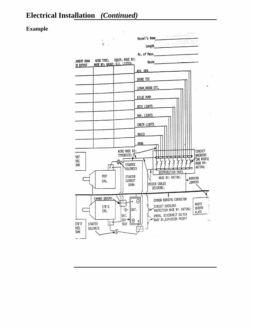
Electrical Installation (Continued)
Example

Fuel Tanks
Information to be Included
Plans must show: • Dimensions • Capacity • Thickness of material • Type of material • Method of assembly • Location of baffles • Connection of vent, fill and supply lines • Means of securing tanks to prevent movement
• Means or type of coating material, if used. (Both internal and external)

Fuel Tanks (Continued)
Example

Piping Systems
Information to be Included
Plans must show all piping systems including: • Engine cooling • Exhaust cooling • Ballast • Bilge • Fuel • Hydraulic • Drinking water • Marine Sanitation Device* system All component parts of each system are to be shown, including: • Piping size • Piping material • Valves • Pumps • Filters • Strainers • Flexible fuel hose The length of flexible fuel hose, model number and manufacture must be listed and must be Coast Guard approved. Flexible hose in excess of 30 inches is permitted as long as the hose meet SAE standard J-1942 and the end fittings meet SAE J-1475.
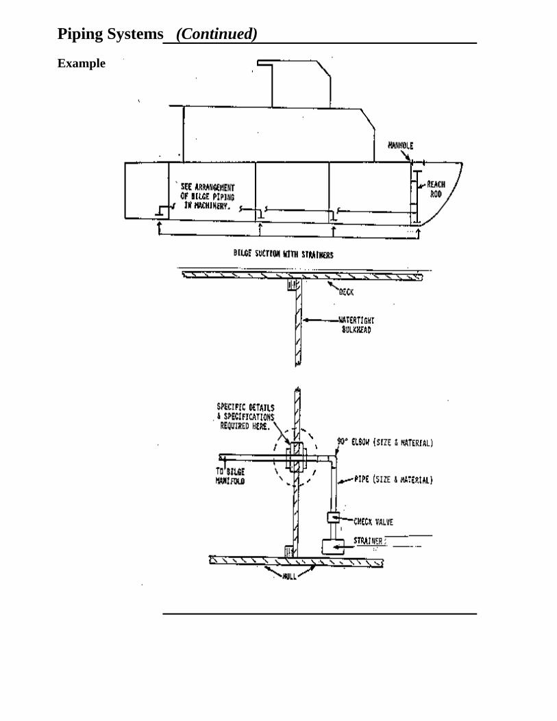
Piping Systems (Continued)
Example

Bulkhead and Deck Penetrations, and Shell Connections
Information to be Included
You must submit complete details of all piping and cable penetrations and all through-hull fittings. Drawings must show • Material specification for fittings • Method of installation • Location of valves • Methods of sealing penetrations Inclusion of these details on other plans instead of a separate plan is acceptable.
Skin Valves All shell connections within six inches of the waterline and
below are required to be fitted with a sea valve. Sea valves and shell connections are required to be metal. In the case of non-metallic hull, materials which can be demonstrated to afford an equal degree of strength and heat resistivity as that of the hull may be considered on a case by case basis.

Bulkhead and Deck Penetrations and Shell Connections (Continued)
Example