united states patent no.: stein date of patent: 0nov
TRANSCRIPT

IlllllllllllllllllllllllllllIIIIIIIIIIIIIIIIIIIlIIIIIIIIIIIIIIIIIIIIIIIIIIUS010847322B2
(12) United States PatentStein
(10) Patent No.: US 10s847s322 B2(4s) Date of Patent: 0Nov. 24, 2020
(54) BIOCIBOMI&'Al, IO ~ KR&PY CONVKRSIONC K I,I.
(sd) Refcrcnces Cited
IJ 8 PAI'IJN1 IX)&'1JMIJNTS
(71) Applicant. Bugsy Solar LLC, Los Altos Hills. CA(US)
(72) Inventor: Emily A. Stein, San Leandro. &'A (US)
4,886,7 s25,324,491 A
12 198'I 1 ovlcy6 1994 Lovley
(Continued)
(73) Assignee Bugcy Solar I,I.C, I,os Altos I lills. &'A
(US)
("
) Notice Subject to any disclaimer„ the term of tluspatent is extended or adjusted under 35U S C. 154(b) by 0 days.
('xCN
I 'Oltl il&iN PA 1 I:N'I 1XX'I )MI JN IS
1012'19/463 I 1 20081014093iS 4i2009
(Continued)
OTHER PUBLICATIONS
(21) Appl. Nox 15/962,931
(22) I'iled: Apr. 25, 2018
(65) Prior Publication Data
This patent is subject to a temiinal dis-clmmcr. JJS Dtficc Action dated.ian 19. 2017 issuui in 1/ S Appl No
14/ I S. 226
(('ontimied)
I'ri mar) Irxanii acr Shannon M (iardner(74) dtiornc/1 &lgeist, or Firm Weaver AustinYilleucuvc & Smnpson LLP
US 2018/0247771 Al Aug. 30, 2018
Related U.S. Applicatiun Data (57) ABSTRACT
(63) ('ontimiation of application No 1-1/315,226. tiled on.Iun 25, 2014. now Pat. No 10.090,1] 3
(Continued)
(51) Int. CI.H01C 9/20 (200G.01)H01 L 51/00 (200G.01)
(52) U.S. &'I.
CPC ....... H01 C 9/2010 (2013.01); H01C 9/2059(2013 01): H01C 9/2072 (2013.01),(Colltllluc'il)
(58) Field of Classification SearchNoneScm applicauon lilc for complete search lnstory.
Prcscntcd herein is a vohaic cd 1 contau»ng light harvestuigantcnnac or other biologically-based electron gcncratuigstructures optionally in a microbial populauon. an clcctronsiphon population having electron conductive propertieswith mdividuai siphons conliaured to accept electrons fromthe lirht harvesting antennae and transport the electrons toa current coilector, an optional light directing system (e.g.,a mirror). and a reguLator having sensing and regulatoryfccdback propcrtics for ihc convcrsiou of photobiochcmicaimicrgy and biochcnucal micrgy to elcctncity. Also prcsenlcxiherein is a voltaic ceil having electricity-generating abilitiesin the absence of light Also presented herein is the use of thevoltaic cell in a solar panel.
21 Claims, 23 Drawing Sheets

US 10,S47,322 B2Page 2
Related U.S..4pplication Data
(60) Provisional application No 61/991.335. filed on May9. 2014. provisional application No. &i[/879,(i12, filedon Sep. 18, 2013, provisional application No.61/957,147. Iiled on Jun. 25, 2013.
(52) U.S. Ci.CPC ....... HBJL 5//0093 (2013.01), Y02 E /0/542
(2013.01), YBJE /()&549 (2013.01)
(56) References Cited
U.S. PATENT DOCUIv[ENTS
S.283,076 B210,090,113 B2
2004 024(77( Al2006;025ii/85 Al2008«0286fi24 Al2010i00«94 6 AJ2010 OZ2424fi A I
20(0(0304189 Al20(i,iffl sl«44 Al2012 0164544 Al2014'03 i 3920 Al2016«0230206 Al
IO 201210"201812 200411"20061(«200h
3 "20109 2010
12 20106,«20116 2012
12"I0148«20(fi
Lovley et alS(einZeikus et alLos icy ei alI ovlcy ct alLovley ei alIon(iciLovley et alI ovlcy ct alKevin et alStetnI ovlcy ct al
FOREIGN PATENT DOCUMENTS
CNJPWOWOW&))VO
1026745292010-218690 A
)VO 2011«08782( A2(VO 2011«113154 AlIV&) 2014 21(D 1 6(VO2017«015306 A2
9 20129«20107«20119«2011
12«20141«2017
01 I II:R PUIII,I(14'I'IONS
Il S Fmal Office Ac(ion da(ed Jui 5. 2017 issued m U S Appl No14«3 I 5,226I S Notice of Allowance dated Jan 2G. 20(8 issued in U S ApplNo, 14«315.226L' Supplemental Notice of Allowance dated Mar 7. 20(8 issuedin I. S Appl No 14«315,226A('xammation Reporr dates( May 12, 2017. issued m ApphcationNo, 2014302421(rh &)(ficc Action dated Aug 14, 2017, issued m Application No201480041193('8 Otiice Action dated Api 16, 20th, issued in Apphcation No201480041193 3 [English sumrmuy].Iapancse Otficc Action dated Aug 16. 201&i in .IP Apphcation No201«-563(82.Iapsncsc Officc Action idatcd May 16, ZOI 7, tssucd In ApplicationNo 20(5-563182Intcinational Scmch Rcport and Wnttcn Opinion dated Mar 27,201« in PCT Appbcation No PCT«IJS20(4 044(78Inteinational Pieliminary Report on Paten(abih(y Dec 29. 2015 inPCT Application No PCT US20(4 044178Chiao, M, et al . "Micromachined nuciobuil and photosynthetic fuelcells," Journal of Micromechanics and Microengineenng. vol 16,
Apr. 26, 2006. pp 2547-2553"Dye-sensitized solm cell", Wikipedia article, as ievised Jun «,
2014 [h(tps aen isikipmba oig'wiindex phpsti(le Dye-sensitizmisolar ccffgdiff=611689947&oldid=607(i9000)I'uuerei, et al, "Genome sequence ol'icrophilus torndus am! i(sunplications for hfc aiound pH OP PNAS vol 101, No 24..(ul I«,2004, 6 pagesHc ct al . '*Self sustamcd phototi ophic nnci obis( fuel cells based onthe synergistic coopei ation between photosynthetic microorganismsand hctcrotrophic Imctenay cnvii on sm tech. Z009. 43, I &id 8-I &i 54Jochum, T et al, "The supramoleculai organization of self-asscmblnig chloiosomal bactcnochlorophyll c, d„oi c mimicsy
Proccedm s of thc National Academy of Sciences (PNAS), vol10«, No 3«, Scp 2. 200S, pp 12736-12741Kumar, A, et al "Does Bioelectrochemical Cell Configuratio andAnode Potential Affhct Biolilm Response'," Brorhem Soc Jiaas,2012. vol 40, pp 1308-1314, doi 10 1042«BST20120130Lo"an. 0 E . "Scaling up miciobial fuel cells and othei bioeiectrochenu-cal systcmsp Apiil (ficmhia/Biorec/mo/(2010), 8«, pp 166«-16 I
McKmhsy, ct al . "Insights mto Actuiobaciffus sucmnogcncs I cr-
mentattve Metabolism in a Chenucaffy Defined Growrth MediumPAppbed and EnvuonmentaJ Microbiology, vol 7(, No i(, Nov2005. 6 pagesNew(on. e( al. "Analyses of Cunent-Geneiating Mechanisms ofShcsvaoeffa lot hi ca PV4 and Shee ancffa oncidcnsis MR-I in Micro-bial iucl ( cffsp Apphed and I'nvnonmcntal Vhmobiology Vo
No 24, Dec 2009, 8 pa esNielsen, L P, et al, "Elecuic Cunents Couple Spatially SeparatedBiogeochemical Processes in Manne Seihmentp Nrr/ure. vol 463,No 25. I'eb 2010, pp 10il-1074Pant, D et al, "4 ieviesv of the substratcs used m nnciobial fuelcells (Ml Cs) foi sustainablc cncrgy pi eduction p Biorcsource 'Iech-nology (2009), doi 10 IOIG(j bioitech 2009 10 0(7zPerkins, R. '*Bactciial nanowircs not what scientists thought theywere,*'&D Mag corn. Aug, 19, 2014, 3 pages [hnp iwss«v rdmagcorn videos 2014 08 bactcrml-nanown ca-not-what-scientists-thought-they-wei e]Rabacy, K. ct sl, '*Miciobial licology Meets Ilcctrochcmistiy.Electncity-Daven and Dnving CommunitiesP 2007 InteinationalSociety for Microbial L'cology. The ISML'ouinal. Feb 2007, Vo.l,pp 9-18Rabaey. R et al, "Microbial fuel cells no~el biotechnology Iorenergy geneiationP Trends in Biotechnology vol 23, No. 6. Jun2005. pp 291-297Rahnnneiad, M, et al shbcrobial fuel ccff as new tcchnolo@ foibioelec(nci(y generation. A revieivp Alexandna L'ngineenng .Iour-nal, vol «4, 201«, pp 74«-756Rosenbmun, M, e( al, '*In Si(u Electrooxidauon of PhotobiologicaiBy«hogan in a Photobioi icchochcmicsl I uel Ccff Based on RhodobactmSphaeioidesPAmeiirair Ciremi«a)Saciei/, L'nmron Sci 6*. Technol,published Jul 9), 200«, 6 pages (A-I)Schleper, et al, "Pic@aper(its gen nov, fmn nov A Novel Aerobic,Hcterotiophic, I'hermoacidophilic Genus and I mmly ('ompnamArchaea Capable of Giosssh around pH 0" Journal of Bactenology,vol 177, No 24, Dcc 19«)5, 10 pa csSchleper, et ai, "Picrop/ahis os/irinae and Pirrophi/ai roin&ar fernnos, gen nov, sp nov., Two Species of Hypeiacidophilic.Thermophilic,Hetetouopluc, Aerobic ArchaeaP Inteinational 3oui-nal of Systematic Bac(enolo *y. vol, 46. No 3, Jul 1996. 3 PiigesStnk, D, et al, "Microbial solar ceffs applying photosynthetic andelec(rochemicaffy acuve oiganismsp Trends in Bto(rxhnolol~, vol29, No I, Jan 201(, pp 4(-49Van de Vossenber . et al, "Bioenerge(ics and cy(oplasnuc mem-brane stabilrty of the evtrcmcly acidophihc, thermophilic aichaeonPicrophilus oshimaeff Extremoplules..lun 1998, 8 pages9/m, .I, ct al, "Recent proff css m clcctrodes for nnmobiai fudcells,*'Accepted MmurnpB Broreiaurce Fechaa/ogy, 102. Jui2011, 46 pp, 10 1016 I biodcch 2011 07 019&Wintennute, E H, et al., "Emergent cooperation in mrciobial metabo-bsmp (&o(scalar Sp«&eau Broiag)s 6 407, 2010, pp 1-7
Xie X et al, "Miciobial batteiy for ethcient eneigy recovery,*'rocecdmgs
of thc National Academy of Sciences (PNAS), volIIO, No 40, Apr 18, 20(3, pp 1«925-1(930 [wmnvpnas.orgicgidoi 10 1073 pnas 1307327 UOIALI Examination Repoit dated Mar 27 2019, issued in ApplicationNo 2018201828A(I Exmnination Repoit dated Jul 19. 20(9, issued in ApplicationNo 2018201828CN Oftice Actton dated Sep 17, 201& issued in Application No201480041193 )(79 Offic Actron dated I eb 27, 2019), issumi in Apphcation No201480041193 "
.Iapanesc Officc Action dated Jun 4, 2019) in JP Application No2018-04 654

US 10,S47,322 B2Page 3
f56) References f:ited
OTHER PUBLICATIONS
Israeli Oliice Action dated Jul 14, 2019, issued in Application No243104Mexican Oflice Action dated Jun 10, 2019. issued in ApphcationNo MXrar2015 017422BR Ollice Action dated Mar 3, 2020. issued in Applicalion No1120150322220IN Oliice Action dated Dec 23, 2019. issued m Apphcation No4246 KOI.NP 2015MX Ofgce Action dated Feb 7, 2020, issued in Application NoMX a 201(r017422Tsupmurt, et al "Recent Development of Enzyme-based Biofuel('cits.'* (18 Yuasa 'Icchmcal Rcport vol 5. Xo 2, pp I -&i, lice. 25,2008, vol ( 6 pagesII Otlice Action dated May 2(i, 2020, issued in Appbcanon No243104Korean Olfice Action dated May 6. 2020. issued m Application No10-2016-7001815
U.S. Patent Nov. 24,2020 Sheet 1 of 23 US 10,847,322 B2

U.S. Patent Nov. 24,2020 Sheet 2 of 23 US 10,847,322 B2

U.S. Patent Nov. 24,2020 Sheet 3 of 23 US 10,847,322 B2

U.S. Patent Nov. 24,2020 Sheet 4 of 23 US 10,847,322 B2

U.S. Patent Nov. 24,2020 Sheet 5 of 23 US 10,847,322 B2
U.S. Patent Nov. 24,2020 Sheet 6 of 23 US 10,847,322 B2
U.S. Patent Nov. 24,2020 Sheet 7 of 23 US 10,847,322 B2

U.S. Patent Nov. 24,2020 Sheet 8 of 23 US 10,847,322 B2
m +o&M0!D Q)-oEto
C O CD
!
(pCo &C 0.0 0
!
o 0I03
0)N0)000
U.S. Patent Nov. 24,2020 Sheet 9 of 23 US 10,847,322 B2
611
607
613
601
603
ElG. 6

U.S. Patent Nov. 24,2020 Sheet 10 of 23 US 10,847,322 B2
FIG. 7

U.S. Patent Nov. 24,2020 Sheet 11 of 23 US 10,847,322 B2
802
FIG. 8

U.S. Patent Nov. 24,2020 Sheet 12 of 23 US 10,847,322 B2
902
903
904
905
FIG. 9

U.S. Patent Nov. 24,2020 Sheet 13 of 23 US 10,847,322 B2
1003
1009
04
1007 1002
03
1004
10071002
FIG. 10

U.S. Patent Nov. 24,2020 Sheet 14 of 23 US 10,847,322 B2
1101
103
1109 104
11071102
103
1104
1107
1102
FIG. 11
U.S. Patent Nov. 24,2020 Sheet 15 of 23 US 10,847,322 B2
SIDE VIEW
1206
120
eMetal Si
NetwoArrangem
1203Semi-
PermeaBarrie
pace 1 207 ConductiveMaterialin 1201
1202 Metal or e 0.22cm Pores Container/Conductive Material Vessel
U.S. Patent Nov. 24,2020 Sheet 16 of 23 US 10,847,322 B2
13061304

U.S. Patent Nov. 24,2020 Sheet 17 of 23 US 10,847,322 B2
1402(VOLTAIC CELLS) 1404 (semi-permeable
membrane)
1406e. donors in
buffer syste
1401(connective
base)A
1405e. sipho
arrangem1403
(e conductivematerial)
1402(vessel)

U.S. Patent Nov. 24,2020 Sheet 18 of 23 US 10,847,322 B2
&D
O
OlA C0
O
Q)00m cC
g) Q&0(0 0
0
0CU
0LA 0o CLIQ
00
CO
5
KEI Q)
E W

U.S. Patent Nov. 24,2020 Sheet 19 of 23 US 10,847,322 B2
thdocked
1606
electron donors
1605
16051606
161609
eleelectron dodonor
1613electron flow
direction
PARALLEL
160T
lectrondonol
electron siphonarrangement
1602 1
electron siphonarrangement
electron siphonarrangement
U.S. Patent Nov. 24,2020 Sheet 20 of 23 US 10,847,322 B2
GridMaster Cathodic
Wire
1708ster Anodic
Wire
1702
Cells
1701
Panel
06hodic
Wire
1703Grid
Grid1703
1702Cell 1 704 1 705
Gn IAnodicWire
U.S. Patent Nov. 24,2020 Sheet 21 of 23 US 10,847,322 B2
1804 Grid
Wires
1802

U.S. Patent Nov. 24,2020 Sheet 22 of 23 US 10,847,322 B2
O
OO
M
NE
CL
0
OCL
OO
OO
OOO
OOOO
OOOO
OOO
OOOO
ZvLU/(hh) le od

U.S. Patent Nov. 24,2020 Sheet 23 of 23 US 10,847,322 B2
CDCD
CDCD
CDCD
CbCNi
&D
4,
CDCD
CD
CDCD
CD
CDCD
CDCD
CD
&D
CDCD
CD
CDCD
CD
CDCD
CD
CDCD
CD ~CD
CD
z.w(e) ~a~ad

US 10,8471
BIOCHEMICAL ENERGY CONVERSIONCELL
('RO)S-Rl&l&ligliN( E I'0 Rt!I,All&I)APPLICATIONS
This application is a continuation of U.S. patent applica-tion Ser No 14/315.226. filed .Iun 25, 2014, titled "1310-('HEMICAL ENERCiY CONVERSION CELL.** which
1&1
clduns bm&etit of priority under 36 U.S.C. SS 119(c) to U.S.Provisional Applications No. 61/957,147. titled "PHOTO-VOLTAIC CELLS AND PANELS,*'iled Jun. 25, 2013,U.S. Provisional Application No. 61/S79.612, titled "l310-CHEMICAL ENERGY CONVERSION CELL," tiled Sep.I R 2013. and U S Provis&onal Application No. 61.'991,335,titled "BIOCHEMICAL VOLTAIC CEI LS." filed May 9,2014, all of which are incorporated herein in their ent&retiesfor all purposes
&o
BACKGROUND
Current volta&c cells and solar panel systems have limitedcthe&cucv'ui! rixliarc co&l&plex u&atc&1als res&flu&g u& s&g-
nihcant associated costs Many solar panels use &vafer-basedcrystallu&e s&1&con cells or cadmium or s&lmon-based tlun-film cells. 1 hase cells are fragile and must be protected frontmoisture through adding multiple protective layers. Panelsare deployed in series for increased voltage and&or in parallelfor increased current. Panels me interconnected tluoughconduc&u&g nu:tall&c w&rcs. An &uhcrcnt problem w&th com-mon systems is the susceptibility of the cells to overheat dueto reverse mirrent tlow when a ponion of thc panel &s shadedand another port&on of the panel is in direct sunlight. Another
&sinherent problem &s that solar cells become less ctlic&cnt athigher tempenstures, wh&ch limits the geographical eti'ec-
1&&cucss of hght couvcrs&ou Io electr&c&tv. Iu&p&ovcuu:nlssuch as arrayed lenses and mirrors improve the fi&cusing ofli ht to increase efficiency but have higher fabrication corn-
«&
plexity and associated costs.Dye-sensitized solar cell (DSSC) is a soLar cell teclu&ol-
ogy based on sem&conduct&ng matcual placed bctwccn a
li ht-sensitized anode and an electrolyte. Fabrication ofDSSCs is not cost-1 ill ct&vc m&d requires cxpm&s&vc matcnalssuch as platinum and mthenium. Additionally, DSSC sta-bility is a concern. as there exists a climate-related sensi-tivity of the liquid electrolyte.
Quantiun dot solar cell (QDSC) teclmology is based ondye-scns&used solar cells but utilizes low b&md gap senu- o
conductor nanoparucles, also known as qum&turn dots, wh&chinclude ('dS. ('d)e, Sb&S&, Pbg and other metalloid salts aslight absorbers 'I'he advantages of quantum dots are thatband gap preferences are dictated by particle size and thatthey offer lugh extinction coefficients. The efliciencies of s.QDSCs are st&11 low w&th over 6% demonstrated for both1&qu&d-tune&ion and sol&d-state cell types m&d Ihc fabricationcosts are st&11 prohib&uvc.
Polymer (and copolyn&er) soLsr cells are inade from tlunfilms of organic semiconducting polymers such as polyphe- ionylene vinylene and copper phthalocyanine. These cellsdifi'er fron& the aforementioned inorganic soLsr cells becausethey do not rcqu&re a bu&11-in electric Iield ol'-N tunct&onsto sc7»&rate clcctrons from holes. Instead, or dnic cellscontain an clcctron donor and an clecImn acceptor In a sspolymeric solar cell, the electron donor is excited hy aphoton. the energy of which is converted to an electron and
,322 B2
hole pa&r. Thc pair d&tl'uses to thc donor-acceptor interfacewhereby the electn&n and hole are separated and current isgcncratcd.
1&xisting photovoltaic panels produce electric&ty fmm ard&lgc ol wavelengths of 1&ght bUI cannot hatucsswt&vc-lengths in the ultraviolet and infrared ranges (except ti&r
recent conceptual studies with polymeric and copolymericsolar panels, although these etfic&encies remain low at3-4%). The available panels also produce httle electricityfrom low 1&ght or d&lliisc light. Increased eltbn in dcs&gn
concepts split light into monocluomatic wavelengths and tod&rect thcsc wavelengths to ddthrent solar cells spccilicdllytuned to those wavelengths and are projected to increase thecllic&cncy by up to 609/w but rcquirc s&gn&licdnt techn&caladvances mid are very costly.
Field experiments involving solar panel technolo y revealthat a drop of 1.1% in peak output occurs for every increasein degrees Celsius past a tlueshold tempemture of 42-44dcgrccs Celsius. Tlus is problemat&c as on hot and sunnydays, the surface temperature of a panel can exceed 90degrees Cclsnis and can often expcrim&ce localized heatbuildup within the panel cmising spots to be as high as g(N)
dcgrccs Celsius duc Io the rellcctivc laycnug nccdcd incurrm&t solar panels. Cold and su&u&y cnv&ronmcnts are thcoptimal conditions for maximal efficiency of the currentsolar panels.
Photovoltaic soLsr panels have been used since the 1950Sfor the conversion of sunlight to electricity. and decades ofteclu&ologicai advancements have only Increased the ef-ficien Io 12-2g.gq/w Rcmcntly. s&gn&licant nauoteclmolog&caladvanccmcnts have been nuulc to &ncrcasc Ilm cfficmncyfrom 10% to almost 29% but at increased design complexityand fabrication cost.
SUMMARY
('ertain aspects of the disclosure pertain to voltaic cellscharactefized by the folio&vina features (a) a buffer con-tain&n an ionically conductive med&um w&th an electrondonor popuiation provided therein& (b) a vessel at leastpartially containing thc bullbr electron donor populat&on, (c)d&1 duodc filr Icccivu&g clcclrons f&u&t& Ihc clccnou ilia&o&
pop&liat&ou dud p&ovuhug elect&ous to Bu cxlcrudl cucU&1 o&
load; and (d) a cathode for donating electrons to, e.g, aspecies m the buffer In certain embodiments, the electrondonor popuiation may be further chamctenzed by a firstspecies of microbe having a first primary metabolic pathwayand a second spccics of microbe havu&g a second prunarymeIabolic pathway, winch is complcmcntary to the tirstpnmary mctabohc pathw»y. In some &mplcmenuitions, nei-ther primary metabolic patluvay is primarily glucose fer-&l&Cutat&VC.
In certain embodiments. the voltaic cell additionallyincludes an ion permeable and electmn donor impermeablebarucr SOT&Brat&ng Ihc bulfer u&to an anode compartment anda cathode compartmm&l, Ihereby prcvcnt&ng the electrondonor population from contact&ng the cathode In someiniplen&entations, the barrier is electronically conductive. Insome implementations, the barrier contacts the anode Somevoltaic celis include a current collector in electrical com-munication with the anode.
In some implemcntanons, the tirst spccms of m&crobeand/or thc a&mond spec&cs of mwrobc comprises light har-vesting antennae. As;m example, Ihc tire& spec&cs ofm&crobeis excited by electiomagnetic radiation in a first band, and atleast one other species ofmicrobe in the buffer is excited by

US 10,847,322 B2
clcclromagnenc radiatiou ui a second banib The lirst bandand the second band do not substantially overlap
In certain embodiments, the first species of microbe is aphototmphic or chenio-tnlphic microbe In certain embodi-ments, the tirst species of microbe is a chemotroph Bnd thesecond species of microbe is a phototroph. In certaincmbodimcnts. thc tirst species ol'icrobe has pili, tibmls,fidgella. and/or a Iilamcntous shape.
In some implementations, the first primary metabolicpatlnvay oxidizes a compound containing carbon, nitrogen, in
phosphomus. or sulfur. and the second priinary metabolicpathway reduces the oxidized compound produced by thefirst primary metabolic pathway. In some implementations,the lirst species ol'icrobe has a plurality of metabolicpallmays. In some cmboduncnts, the lirsl primary metabolicpatluvay and the second pnnlary metabolic pathway eachparticipate in cellular respiration. In soine iinplementations,the firs species ofmicmbe is a naturally occurring microbialspecies.
In certain embodiments, the voltaic cell additionally zo
includes a populauon ol'lectmn siphons, whcrc each elec-tron siphon includes mi electron acceptmg component forreceiving electrons front the electron donor population. andan electmn conducting element for directly or indirectlyconducting electrons froin the electmn accepting conlponentto the anode. In some cases. the electron siphons have amedian principal dunension of at most about 500 microm-clcrs. In certain emboihmcnts, thc electron siphons logclherform an assembly witluu thc bulTer, with thc assmnblyconfi ured to conduct electnms froin the electmn donor lopopulation to the allude
Another aspect of the disclosure concerns metlxld ofconverting chemical and/or light ener y to electrical energyby operating the voltaic cell having any combination of theli:alurcs prcsenlcd above ui llus secuon. ls
Another aspect of thc disclosure penmiw lo bufii:rs forioltaic cells. Such bufibrs may bc chacdcleruzed thc follow-ing components (a) an ionically conductive medium; and(b) an electnm donor population provided in the ionicallyconductive medium In certain embodiments. the electron do
donor population includes: (i) a tirst species of micmbelliivlllg d lilst prilllaiy lllcIBbollC ptilhwdvs Bui! (11) B SCcolldspecies of microbe having a second pnmary metabolicpiilhwtiv; whlCh is ColllppclllCIlldry lo lhC tlrSI prllllsisy IIICta-bolic pathway, where neither primary metabolic pathivay isprimarily glucose fermentative
In certain embodiments. the first species of micmbeand/or the second species of microbe are light harvestingant ciuuie. As ml example. Ihc lirsl species ofnucrobc may becxcttcxt by clcctromaguetic radiation in a first band. mid at o
least onc otlu:r spccics of nucrobc in thc bufibr may beexcited by electromagnetic radiation in a second band Inthis example, the hrst hand and the second band do notsubstantially overlap
In certain embodiments, first species of microbe in the s.bufii:r is a pholotrophic or chemo-iropluc microbe. As anexample. the lira t spccws ofnucrobc is d chcmotroph and thcsecond spccics of microbe is a pholotroph.
In certain emlxldinients of the buffer, the tirst primarymetabolic patluvay oxidizes a compound containing carboii, si!
nitrogen. phosphorous, or sulfur, and the second primarymetabolic path~ay reduces the oxidized compound pro-duced by Ihc tirsl prnuary metabolic pathway. In somecx unples of the buficr. Ihc tirsl pnmary melabolic palliwayand Ihc second pnmary metabolic pathway mich participate ssin cellular respiration In some buffers, the first or secondspecies of micmbe has a plurality of inetabolic patluvays In
some bufi'cr examples. thc lirst pnmary metabolic pathwayand the second prinmry metabohc pathway each participatein cellular respiration
In some butTers. the hrst species of microbe has pili,fibrils, tlageila, and/or a filamentous shape. In some butfers,the first species of microbe is a natumslly occurring microbialSPCCICS.
In certain cmbodnuenls. the bufihr additionally uicludcs apopulation of electron siphons, where each electmn siphonincludes an electron accepting component for receivingelectrons from the electron donor population. and an elec-tron conducting element for directly or indirectly conductingelectrons from the electron accepting component to theanode In some cases. the electron siphous have a medianpuncipal dimension of at most about SOO micmmcters. Insome examples, the siphons collectively make up an assem-bly within the buffer. which assembly is configured toconduct electrons fmm the electron donor population to theanode
Another aspect of the disclosure pertains to voltaic cellscharaclenzcd by lhc following features. (a) a bufibr cun-talllillg dll iolliCally'ullduCI Ii C ulixllulu vvilll (I) Bll CICCIrolldonor pnpulation provided therein, and (ii) an electronsiphon population provided therein: (b) a vessel at leastpartially containing the butTer electron donor population; (c)an anode filr receivin electrons from the electron donorpopulation and providing electrons to an external circuit orload. Bnd (d) a cathode for donating clcctrons lo a species in.c g., the buffi:r. In certain mnbodimcnts, each clcctron siphoncontains an electron accepting component for receiving,electrons from the electmn donor population. and an elec-tron conducting element for directly or indirectly conducting,electrons from the electron accepting component to theanode
In some implemcnldiions. Ihe clcctron siphons lmvc amedian principal duucusion of al most about SOO nucrom-etcrs hl solllc illlplculcllttltiiuls, lllc cbccllon siphoustogether inake up an assembly within the buffer, whichassembly is configured to conduct electmns from the elec-tron donor population to the anode. In some implementa-tions. the electron siplmns include a docking moiety fordocking with Ihc clcctron donor population, bul nol lysulgcells conlauling Ihc clcclron donor populauon
In cirlain cmbodnnenls. thc voltaic cell additionallyincludes an ion pernleable and electron donor impermeablebarrier separating the butTer into an anode conipartment anda cathode compartment, thereby preventing the electrondonor popuiation from contacting the cathode. In certainembodiments, thc voltaic cell additionally uicludcs a currentcollector ui electrical commurucanon with thc tmodc.
Auolhcr aspect ol'he disclosure pcrlanm lo bufi'crs lorvoltaic cells. Ivhich buffers may be characterized by anionically conductive medium includiilg (i) an electrondonor population: and (ii) an electron siphon population. Incertain embodiments, each electron siphon includes an elec-troll BCCepllllg ColupullCIII for Iix'Clvillg CICCIroils flolll lllC
electron donor population. and an electron conducting elc-lllCBI fol flic'Ctlv'r llldllcctlv'oilituClillg CICCIIOIIS lrolll lllC
electron accepting component to the anode. In certainembndiments, the electron siphons have a median principaldimension of at most about 500 micrometers. In certainembodiments. the electron siphons collectively make up anassembly witlun Ihc buficr, wluch assembly I ~ conligurcd Ioconduct electrons from thc electron donor population to IhedllodC hl CCrld ill clllbodllllCIlls, IIIC CICCIroil SlphollS IBCIIBIC
a docking moiety for docking with the electron donorpopulation, but not lysina cells containing the electron donor

US 10,847,322 B2i
populanon. Thcsc aud other features ol'he disclosedenibodiments will be set forth below re ardi&ig the assoc&-
atcd draw u&gs.
'lliese and other features of the disclosure will be furtherdcscnbixl below w&th rcfcrcnce Io Ihe drawm s.
BRIEF DESCRIPTION OF THE DRAtVIN(iS
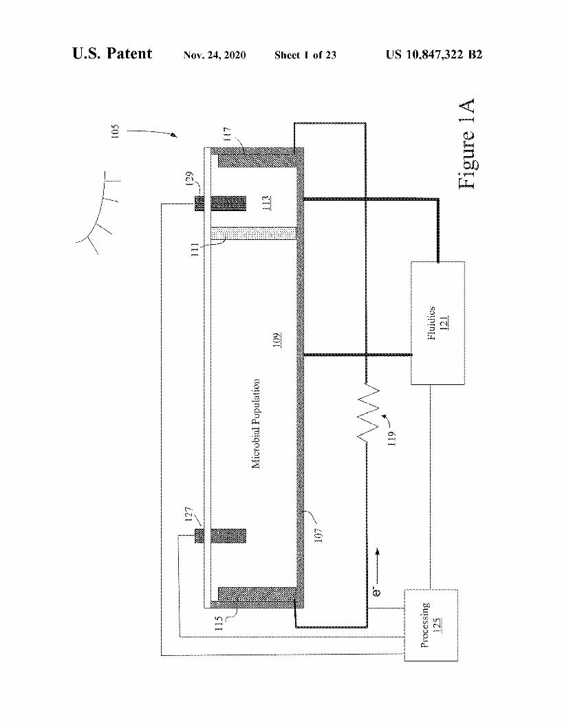
FI(i. 1A schematically depicts an energy conversion cell.FIGS. IB-1D dcpic& variauom ol'Ihe cell six&wn in FIG. &o
1A.I 1(i 2 presents an example of an inunersible open systeni
voltaic ceil.FIGS. 5 and 4 depict li ht-conversion systems employing
electron siphons. I
FIG. 5 depicts a photosystem coupled to an electrons Ip ho &1.
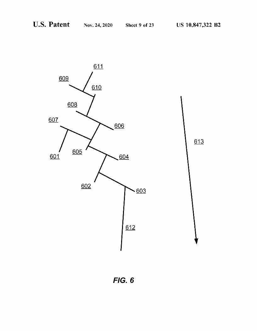
FIG. 6 presents B schematic ol'lectron siphons andelectron donor population arrangement.
FI(i 7 presents a schematic of a second arrangement of &o
electron siphons and microbial cell population.FI(i. 8 presents examples of several electron siphonsFI(i. 9 presents a schematic of a varied array of electron
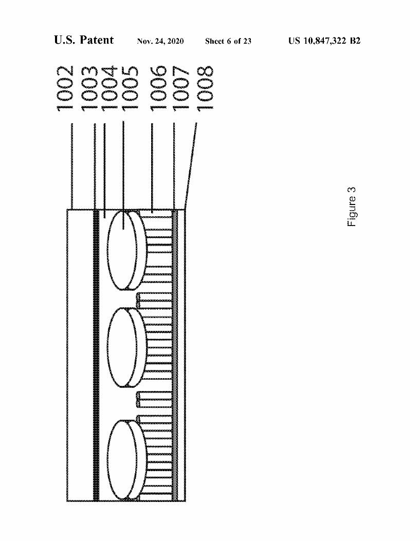
siphons.FIG. 10 shows thc use ol'hmtron siphon to capture
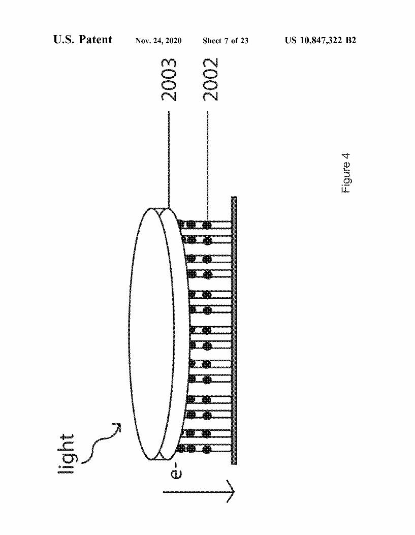
electrons generated fro&11 &1&etabolic processes.II(i 11 shows the use of electron siphon to capture
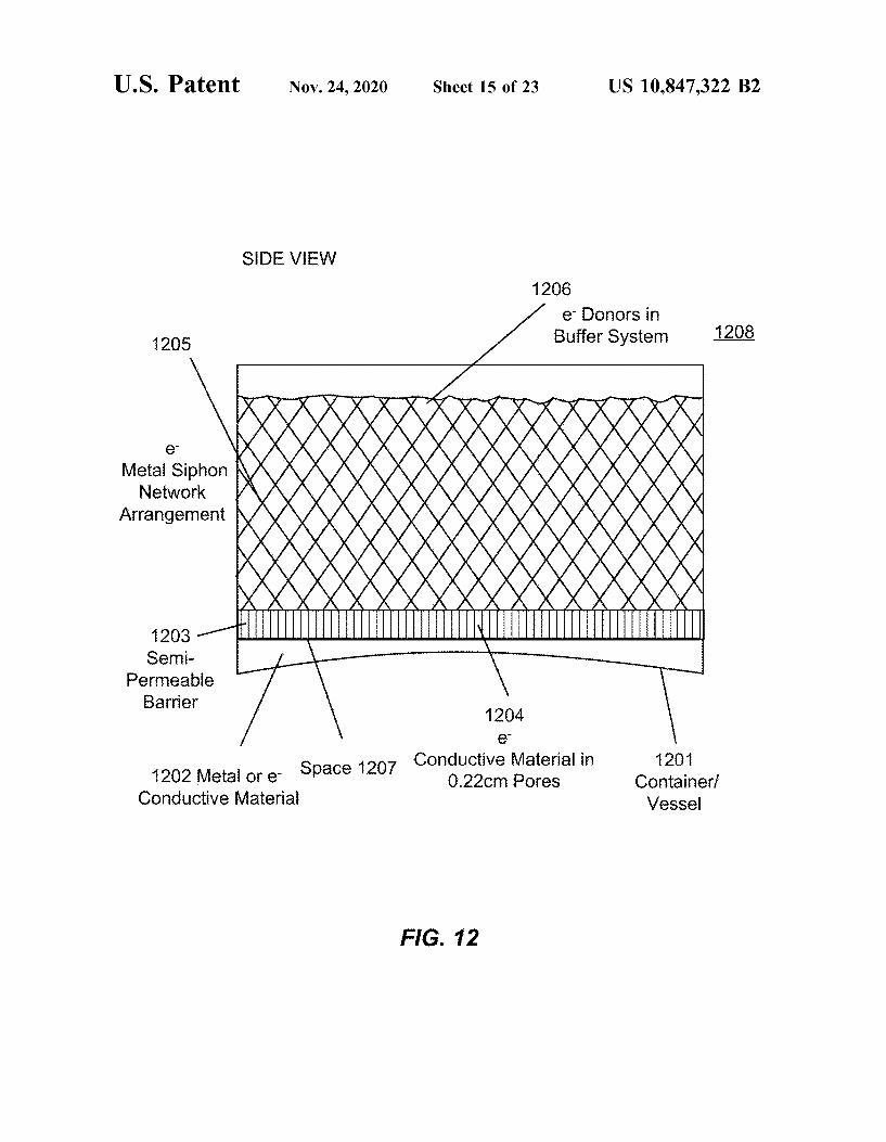
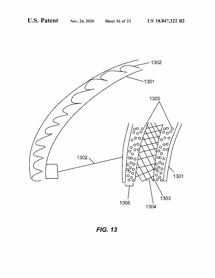
electrons generated fmm liposomes.FIG. 12 presents a side view of a voltaic cell.FIG. 13 presents a schematic of a voltaic tube. 3&l
FIG. 14 prcscnts a schema&&c of voltaic cell pillars.FIG. 15 presen&s an arrangcmcnt ol c&rcuit co&uiccni &ty &n
a voltaic cellFl(i 16 presents an arrangement of electmn donors on
electron siphous in a parallel mailner. 3&
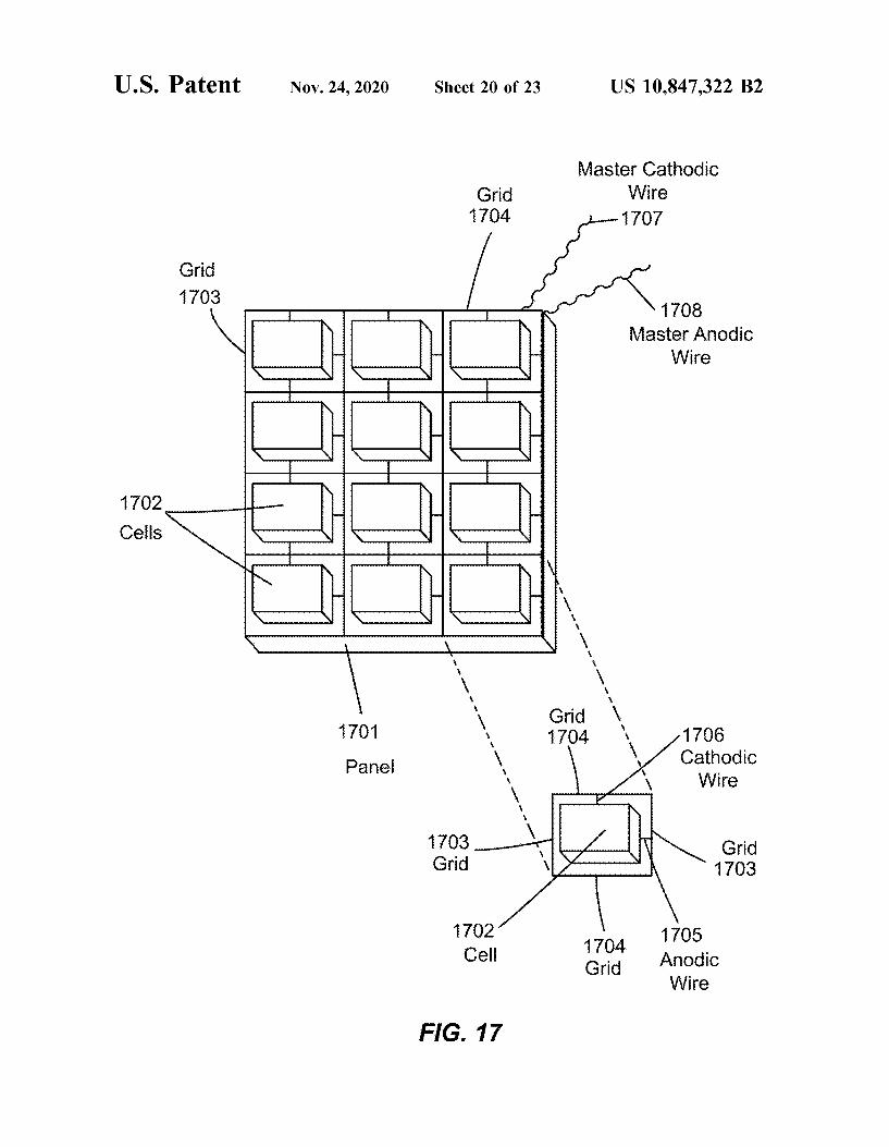
FI(i. 17 presents a schematic of an armmigement ofvoltaiccells in series.
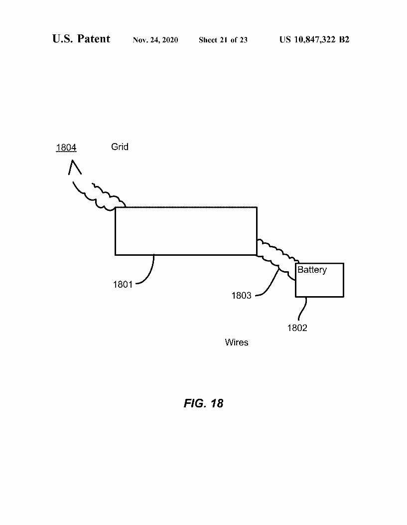
FIG. 18 presm&ts a schematic of a volta&c pm&cl and abaucry.
IIGS 19 and 20 are plots of power output over tinie for do
voltaic cells constructed in accordance with certain embodi-BIc&tts
DESCRIPTION OF AN EMBODIMENT
I )efinitions
Unless detined otherw&se. all teclmical and scientihcIcons usci! heron& have Itic saute &&&csun&g ils coun&tool)'nders&ood
by onc of ordu&ary a)all in Ihc ar&. Venous O
sc&m&tilic d&ctiooanes tha& &ncludc Ihe &amis uicludcd here&nare well known and avaiksble to those in the art Anyniethods and materials similar or equivalent to thosedescribed find use &n the pmsctice of the embodimentsdisclosed. s.
11&c terms dcliued unmcd&a&cly below are more fullyundcrs&ood by rcfi:rance Io thc spimilicdlion. 11&c deli&ut&ons
dre provided to dcscnbe particular cmbodimen&s only andaidin in understanding the complex concepts described inthis specificat&on 'I'hey are not intended to limit the full ioscope of the disclosure. Specifically, it is to be understoodthat tlfis disclosure is not lim&ted to the particular composi-tions, systems, des&gns, me&hodologies. pro&ocols, and/orreagcn&s dcscribcd, as Ihcsc may vary, dcpcndu&g upon thecontcxl Ihey are used by those of sk&ll in Ihc art. si
As used in this specitication aod appended claims, thesingular forms "a". "an", and "the" include plural referents
unless Ihe contcn& and contcx& d&ctatcs otherw&sc. Forexample. reference to "a cell" includes a combinat&on ofnvoor morc such cells. Unless u&d&cated otherwisc, an "or"co&&junction is used in its correct sense as a l3oolean logicaloperator, encompassing both Ihc select&on of features in Ihcalternative (A or l), where the selection of A is nn&tuallyexclusive from B) and the selection of features in conjunc-tion (A or 13, where both A and l3 are selected)
yL&ght-harvestin antennae" are biochemical or chemicalstructures capable of beu&g exc&ted by 1&ght cncrgy. Ofinterest. light may excite the antennae to a state allowinthem to gcncrate elcctncal or clcctrochmn&cal cucrgy. Some-times, a photosynthetic microbe conte&ns light harvestingdulC&1&&BC.
An "election donor" is a coniponent that donates electn&usas part of a process that involves conversion of energy frommsdiation (e g., light), chemical components, n&echanicalmanipulation. or other process. In this disclosure. examplesof electron donors uicludc pho&osyn&hct&c and non-pho&o-synthetic microbes, light-harvestin antennae, and pig-u&cols
A 'photosynthetic micmbe's a niicrobial cell that useslight ener y for growth mid metabolic pmcesses Suchnucrobe typically contai&is hght-harvesting antennaecapable of harnessing light energy and electron transportcomponents. which may be en&bedded in the cytoplasmicmembrane and/or mcmbrdnc invaguiauous a&xl/or mcm-branc vcsicles and/or organelles.
A "pigment" is any composit&on capable of bemg excitedby light energy, typically through wavelength-selectiveabsorpt&on A pigment is one light-harvestmg antennae or acomponent thereof. A pigment may be synthetically orbiolo ically produced.
A '*non-photosynthc&ic microbe" is a m&crob&al cell tha&
docs not need hght energy for growth and mctabohc pro-cesses. Such nucrobc may contain clcctron transpor& com-ponents, which n&ay be en&bedded in the cytoplasmic mem-brane and/or membrane invaginations and/or n&embraoeves&cles and/or organelles.
An "electron siplmn" is small structure cont)Faired tormuovc elec&rona Ibom Ihc light lrdrvcsting m&tarmac andd&rcctly or indirectly transport Ihc electrons Io a currenlcollcclo& (sonic&BI&ca sc&vulg Bs ilu clcclrodc) ol a voltaiccell. In certain embodiments, a siphon contains one or moreelectron accepting elements (e 8 . electron coordinating &noi-
eties) attached to (e, on the surface of) an electrontrmisporting structure. The electmn transporting structuremay bc a single atom tluck (e.g . a grdphenc matnx) or maybc mult&pie atoms Ihick.
Au "clcctron s&phon matnx" is a collection ol'lcctronsiphons that may substantially overlap with one another Insome embodiments. an electron siphon matrix provides aconductive pathway that spans nndtiple individual electronsiphons. In some embodiments„ the matrix provides a con-ductive pathway extcnduig Irom a current collector ol avoltB&c cell well »lto il bufibl v;1&CI'c thc mB&rix cou&Bets &I
plurality of biolog&cally-based electron gmicrat&ng stnic-tures. In some implenientations. the electron siphon nmtrixis an arrayed co&nfigumtion of elect&on siphons.
An "electron conductive material** &s a material thatenables the transfer of electrons from one location of theelectron conductive ma&anal Io ano&hcr loca&&on. Thc elec-tron conducnve material nuiy bc clcctron&cally conducuvc orsmniconducnvc. It nuiy conduct holes. In some embodi-mentg the electron tmnsporting stn&cture of an electronsiphon contains an electmn conduct&ve niaterial

US 10,847,322 B2
Introduction und ContextPhotosynthetic microbes and plants remain the most e)fi-
cient at corn erring light ener y into other usable fiinns ofenergy at about 40-50% light absorption. It is estimated thatthe average rate of energy capture by photosynthetic orgmt-isms is 130 temwatts Iobaiiy, wifich is approximatelysix-iunt:s hugt:I flan thc ciurcnt powc& ciinsUnipiion ciipa-bihiics of the hunuin civ&hzat&on (Ncdison, 1999; WIUImarsh1999: Steger. 2005; Iinergy Information Administration,200/&). Photosynthetic microbes contain iight-harvesting &0
pignients and antenna systems or reaction centers in theirmembranes to harness the energy delivered by a photon.Electron carriers senaiiy pass excited electrons tiuough theelection tidnsport chal&i Bnd suuU)tancotlsl)'acihtatc thccoo&Quid&cd cffort of prolon scpd&it&wint&cross Qu: ntcnibIiulc I
to uenentte potential energy'Hiere are two types of photosynthesis, nonoxygenic and
oxygenic Nonoxygenic photosynthesis is thought to histori-cally precede oxygenic photosynthesis and does not produceoxygen. Oxygenic photosynthesis occurs in plants nnd cya- zo
nobactcria and uses HSO as mi eicctron donor for pix&tutro-phy. Nonoxygenic photosynthesis can utilize hydro en, sul-fur and certain con£s as eiectron donors fiirphototn1phv.
1he docuniented abihty of maximal light harnessing hasbeen identified in green sulfur bacteria that reside almost I
mile below the ocean*s surface in deep-sea therma) ventswhere very muumal hght reaches these nncrobcs. Tiu:scmicrobes can uttiize n0trly 100'/o of thc residual hght tnnon-oxygenic photosynthesis i i&
'Hie use of photosynthetic micnibes to generate usableenergY has ti1cused &naiiiiy on biofuei generation
Disclosed herein is a microbe-based electricity generatingcell bavin lower energy fabrication processes. producinglugh light-io-clectuc&ty conversion rates, having regulators iidnd hdvulg lt:ss gcographnxil const&i&hits coulpBicd to et&t-
rent solar tcciuiologics Thc cell may bc rustomtzable toaddress requirements of geography, climate. season, stnic-turai needs. etc In certain embodiments. a cell has one ormore light-harvesting antennae populations and optionally do
includes one or more of the following features; electronsiphons havuig electron conducuvc properties, an op&ice)
coupluig system, and rcguiator havuig sensm and regula-tory fcedbtmk properucs In some designs. &he cell haseiectricity-uenemstmg abiiities absent light in some tmpie-mentations. the cell is deployed in a soLsr panel
In one fomi. a voltaic cell includes a vessel contaimn abufi'er system. a microbial cell population. a conductivec)cczron siphon population tmd a current collector (c.g.. aw ire). 0
In ccrtaui cmboihmcnts, a voitaic cell mcludcs a vcsseicontaining a buffer system, a micmbiai cell population, aneiectron siphon population and a current collector. In otherentbodiments. a voltaic cell includes a vessel containing abuQ'er system. a nucrobiai cell population. a conductive s.election siphon nlattlx, Bnd B wire (Bn cxanlplc iif 11 cUIrcnlco)Ice&or). In other cmboduncnts, a voitaic cell mcludcs ateasel contauun a buffi:r system, a nucrobial ccli popula-tion, a conductive eiectnxu siphon inatrix, and a currentcoiiector. In sonic aspects, a voltaic cell includes a vessel ii!
containing a light harvesting antennae popuLStion. a bufiersystem. an electron siphon population. a conductive electronsiplx&n matnx, a mirror system and a regulator system. Thec)cczron s&phon population and thc electron siphon ma&oxmay bc phystcdliy diffhrent structures. w&th ihc popuiat ton sicontaining functional groups that facilitate docking v itheiectron donor and the niatrix designed to transport electrons
from thc populauon to mi electrode. Thc stphons of thcpopulation may move aixiut ivith the micmbes while thesip)anus of the matrix may have a hxed )neat&on In soineaspects may, a voltaic cell includes a vessel containing alight harvesting antennae population. buffer system. armyedelectron siphon population. electron conductive material,nurror system a&Id regulator system. In yet other aspecIsmay. &hc voitaic cell uicludcs d vessel coute uting a m&crobiaipopulation, buffer systeni, electron siphon population, regu-iator system and char e store e device
i&i(i IA schenmticaiiy depicts an energy conversion cell105 having a contaimnent vessel 107 v hich holds in itsinterior 109 a Quid in which one or more microbiai popu-lations exist. Cell 105 also includes a cover clement 131fitted on top of vcssci 10'7. Elcmcnt 131 is trausparcni tontdiation in a ivaveien th mange to which the microbialpopulation responds Optionaiiy. cell I l)5 mciudes an ioni-cally permeabie barrier 1)1 disposed within the vessel It)7to prevent microbes and/or other electron donors in there ion 109 from passing into a compartment 113 on theopposite s&dc of pcnncablc barrier 111. It should be under-stood that permeable barrier 111 is opt&onai mid somcumcsonly a singie solution is provided within vessel It)7.
('eii lt)5 wiii include an anode )15 and a cat)inde )17eiectronicaiiy separated from one another by ionicaiiy con-ductive Quid in compartment 109 and optionally in com-partment 113 if present. During operation, the microbiaipopulation(s) in compartment 109 produces electrons Iha1
arc col)ac&cd at anode 115. These electrons work by Qowuigi&rough a load 1)9 in a circuit coupiing catliode )17 anda&aide I)5 lf conipartment 113 is used. it niay Inciude aseparate microbial population. In scute itnpienientatioits,microbes in compartment 113 donate protons or other posi-tiveiy charged species to cathode 117. The microbes in fluids109 and 113 convert energy by diifi:rent mccirdnisms. Invarious emboduncnts. at least tiu: nucrobes w&tlun compart-ment 109 are photouophic.
In certain embodinients, a Quidics systeni 121 is coupledto the vessel )07 and optionally has sepamste ports fiircompartments 109 and 113. The fluidics system 121 mayinclude various elements such as a reservoir for holdingmake up Quids Q&r compartments 109 and/or 113, one ormorc pumps, one or morc prcssure gauges, mass Qow ratemeters, baffies. and thc lii e. The Qunhcs system 121 maypmvide fresh buffer solution antffor nucrobes to cell )05 ltmay also deliver one or more of various reguiatuig agents tothese Quids. Such reguLating agents may include acid, base,salts, nutrients, dyes, and the like.
Ccli 105 may also uitcrfacc with a controlicr 125 thatcontrols Quiihc system 121. Conuollcr 125 may have onc ormore other functions. For example, &1 may reccivc inputfrom various components of the system such as the circuitcouphng anode H5. cathode 117, the fiuidics system 121,and/or sensors 127 and 129 provided in compartments 109and 113, respectively. The sensors may monitor any one ormorc rclcvant operating pdramcicrs for ceil 105. Examplesuch parameters utcludc tmnpcrature, cimmicdl properties(c g., component concentration and pH), optical properties(e g, opacity), electrical properties (e g., ionic conductiv-ity), and the like
FICi. IB depicts a variation of cell 105. Specifically. thefigure depicts an alternative ceil 135 bavin an anode plate137. a cathode piatc 139, and a compurunent 141 be&warn&
plates 137 and 139 as dciined by a spaccr 143. )9&thinconlpitrtnlcnt 141 B dn Itinnuiliv'ondUctlvc mcdiUnl. Anixh:plate 137 may contain or be made fmm a semipermeablematerial that a)in&vs ionic comnmnication between the two

US 10,847,322 B210
sides of Ihc plate but does nol pcrnut passage ofmicrobes ormicrobial components Provided on top of anode plate 137is a population 145 of phototrophic microbes containingphoton harvesting antennae.
FIG. IC depicts another variation of a cell 105. Specifi-cally, the figure depicts a first compartment 147 connectedto a second compartment 149 by a flurd comparuncnt 151.Witlml compartment 147 is a Iirst clcctrodc 153, which iselectronically conductive and may be ionically conductive.A layer of or anic photosensitive electnm generators 145 la 10
disposed on top of electrode 153The electron generators may include light harvesting
antennae Bnd. in some cases. electron siphons Bs well. Layer145 nuiy ulcludc a population of phololropluc microbcs,microbial membrane bound photosyslmn, vesiclcs conlain-ing a photosystem. and/or other photosensitive organic ehx-tron generators Within compartment 149 is a second ehx-trode 155, v hich llss the opposite polarity of electrode 153and is electronically conductive and optionally ionicallyconductive. Compartment 151 may contain a semipermeable Iomalenal Ihal allows ionic conunuiucduon belwecn compart-ments 147 mid 149 bul docs nol pemui the difl'usion ofphototnlphlc mlciobcs, ouci'oluBI luclubfBnc coulpoaculs,etc present in layer 145 from compartment 147 into conl-partment 149. Iilectrons harvested from the microbial popu-lation 145 are transferred to electrode 153 in compartment147, which then pass tluough a connected conductive ele-ment 157 (C.g., a wire). A second conductive clement 159 iscoiuuxlcd to electrode 155.
lq(i Il) depicts another variation of a cell 105. Specifi- loc;lily; thc figurc depicts a split coalpartlucllt 161 colltalillaga tirst electrode 153 as described for the embodiment of 11(i.IC bavin direct contact with a layer 145 containin pho-totrophic nucrobial Bnd/or microbial membrane componentpopulation containing photon liarvcsling mllennac. Com- 11
parnnmll 161 also contains a second electrode 155 Bs
descnbcd ul the cmboduncnt of FIG. 1C of opposite polantyseparated by a senupermeable barrier 163 enabling ionexchmlge throughout the cell but inhibiting the ditfusion ofphoton harvesting antennae 145 into the space surrounding do
electrode 155. Electrons flow to first electrode 153 Bnd thenliuough d conductive clmncnt 157 lo B circuit. Positivelychdrgcd spix'Ics BUch Bs prololls 01 holes Iuiiy'low 0110Ughthe second electrode 155 by conductive clmnenl 159. Hav-ing the same effect. electnms may flow into electrode 155fmm a load electrically connected to first electrode 153
The light-conversion system may include an anode posi-tioned directly adjacent to the electron siphon to collect theclccxrons from the siphon and pmducc an ekxlricdl currentin a circuit containing an anodeand d cathode. The circuit 0
may be coupled to a conversion module filr Bn clectncal gndol'thcl'ystc'Iu
In one form, a disclosed nucrobial energy conversion cellincludes a vessel containing a buffer system. a light harvest-ing antennae population, and a conductive electron siphon sspopllhlnou. Ill solllc Bspccm ol fllc cUlrclll ihsciosillc. thccell can ulcludc a vessel containing Ihe hghl harvestingantennae population, buifbr, conductive clcctron siphonpopulation, mirror system and regulator system.
In sonic embodiments, a light conversion system includes ioa light-harvesting antennae component popukation andmoditied conductive electron siphons for the improvedcfiiciency of light conversion to elcclncily al reduced com-plcxllv dill cost.
In ceruiin cmboduncnts, a light-conversion system siincludes a bufl'ered electmlyte solution surrolulding anlicrobe-derived light-harvesting antennae population, the
population having muluplc light-harvesting anlcnnac pcrcolnpoflcltl Bill lvhcrc tile conlpollcttt popUlatuln has Bo
abihty to harvest light over a bmad range of wavelengths,including ultraviolet and far red light and can harvest lightover a range of intensities, includin difihse hght. Thepopulation can include one or nlore microbe species includ-ing B nuxlurc ol photosynthetic aud nou-pholosvnlhelicnucrobcs, membranes components dcnved from lhcnucrobes or vesicles containing li ht-harvesting antennaecmnponents and electron carrier conlponents
In some embodimenlg a light-harvesting antennae popu-lation contains photosystenls„ lvhich include light-harvest-ing ptgntents or electron carrier molecules and reactioncenters. These clcmcnls Brc descnbcd I'urthcr regarding FIG.5 below. In some unplemmltdtions, a light-harvcstulg mltcn-nae population contains a range of different hght-harvestingpigments and photosystems and may have similar electroncarrier nlolecules I ixamples of individual conlponents of alight-harl esting antennae population of the disclosedembodiments are presented in Tables I and 2.
Thc light conversion system may contain clcctron siphonshaving clcclron-scavcngulg and conductive midior scmi-cmlductive properties over a broad tenlperature mange. I ilec-tron siphons may be modified conductive and semi-conduc-tlvC 111 llature Bfld;ll'0 lllodltled ul a otallllel'o in;ulltalllelectron conductive properties. As descnbed more idlybelow. electron siplulns can be individual or multimericnanomds. Banotubcs, ndnowircs, nauoparlicles, nanonel-works, nanolibers, quantum dots, dmidnmers. nanoclustcrs.nanocrystals or nanocomposites and can contain carbon,sihcon, nletal. metal alloys or colloidal liurther, individualelectron siphons of the disclosed embodiments can rangefrom I to 900 nm in length and nulltimers that range from0.9 to 4 um in length. In some embodunents, the microbesthemsclvcs producmi electron siphons to provide a naturalIllcchalllslu Iol cxpclllllg excess clcclrolls.
FICi 5 depicts Bn example electron siphon ul usc. In tlusexanlple, a single lvalled carbon nanotube 505 was activatedby I I(.'I, washed and modified v ith I.-Arginine by chemicalcrosslinking to generate a biologically compatible electronsiphon. The modihed carbon nanotube 505 was mixed witha nucrobial populauon conlduung Ii Jtt-harvesting pigmentsdill Ck:Ctroll Cairlcl Colupollcum 111 thClr IIIClllbldlu:S.
A pholosystcm may operdlc shown ul FICi. 5. In someembodiments, the photosystem exists in the cell membraneof a living organisnl In some enlbodiments. the photosys-tem exists in a membrane derived from a living organism butis no ion er part of that organisnl. In other embodiments, thepholosyslem is incorporated in a synthetic miccllular struc-ture. SuCh structures can bc crea(cd by tcclu»ques Intown inthe Brl such as sonicaling oil and lipid in a solvcnl withdetergent. 'tile resultin nlicellular stmctures can be spikedwith the required components of a photosystem. Such com-ponents typically include a reaction center such as a mol-ecule of chlorophyll a, light harvesting pigments, and elec-tron slniltling molccules. Certain pigment molcculcs msyserve as both thc light harvcsung pig/Beats and electronshullllllg ulolccUlcs.
As light hits the li ht-harvestin pigments in the micro-bial membrmles. the excited electrons are passed direction-ally to electron carrier conlponents (antenna accessory pi-ments ut FICi. 5i in the membrane and to an electronshullling component that passes the clcctron to a terminalelectron acceptor, ul tlus case, the modiiicd carbon nano-tube. Electron tlow oul of a microbuil membrane onto anelectron siphon results I'he electron flow can then beharnessed by a neighboring anode, such as a nletal plate or

US 10,847,322 B212
wire lo maximitm Ihc flow ol electrical currenl oui of apopulation of microbes When the net flow of electrons onone portion of a cell (at one electrode) ditfers signiticantlyfmm another portion of a cell (at a ditferent electrode), anelectrical current can be generated.
Electrons may flow from the photosystem to the anode by1 arious means Somcnrncs, thc nucrobcs are directlyattached lo Ihc anode as a lilm or other adhcrcnl slruclure.ln such cases, the electrons genenated by the plxltosysteniniove directly fmm the photosystem to the anode In other Io
cases, lhe photosystems are not attached the anode andelectron flow out of electron siphons in solution where theelectron may be captured and transported by B mediator inthe solution. In a similar nnboduncnl, the electron is dcliv-cred lo a conducUvc network hnkulg Ihc anode lo thcmicrobes or other photosystem containing elements in solu-tion Such systems may be a nanostructure network. path-way or other arnangement to maintain linkage from anelectron siplmn to the anode for example. In cermin embodi-ments, the photosystem corresponds to B light harvesting lcdiilollllii.
While photosystems arc frcqucntly described as a sourceof electrons for the disclosed embodiinents, non-photosyn-thetic biochemical pmcesses that pmduce electrons niay beused in place of or besides the photosystems go, v henappropriate. reference to photosystems Bnd similar termsmay be considered to include metabolic and other biochemi-cal systems Ihal produce ehmlrons avmlablc for donalion lodll dliixlc ill Bll cllcrgv couvclsiou cull.
Vessel and Associated I lardware for Voltaic Cell uiIn its basic embodiment. an important function of a
voltaic ceil is to harvest photons and harness excited eln-trons contained within the ceil to generate elecuical currentusing photosynthetic microbe and photosynthetic microbialmcmbranc populauous. The cell mdy mclude a leak proof liVessel or housing lhr lhc nucrobial ener y conversion ccflmcdnun and microbial population. In some emboduncnts,the niicrobial energy conversion cell additionally includeselectrodes. sensors, senti-permeable barriers, ionic conduc-tive material. v,ires and the like. do
Typicafly. the cell should be designed to accept externalradianon mid couvert Ihc energy thcrcin to cxcilcd clcclronsofthc light harvesting nitcnnae of nucrobia1 membranes andlo provide conductive matcnal for Qle harnessing of resul-tant high ener y electmns genenated by the electron trans-port chain ivithin each membrane of a microbe.
Microbial energy conversion cells of the disclosedembodiments can have hdl access to the environment andcmi be consuuctixl In a maiuicr lo enable photon conversionat lempcraturcs ranging from —20 dcgrccs Cclsnis to 65 o
degrees Celsius aud weather ranging from complete sun locloud or foa cover Micnlbial energy conversion cells of thedisclosed embodiments can also be portable and can havevariable access to the environment, as detemlined by theuser. ss
In certain nnbodimenls. vessels cmi withstand lngh tcm-pcrdlures (c g., about 50 C or greater) and uuemal pressures(above aunosphenc) of about 50 Pa to about 10 kPa, ofabout 500 Pa to about 3 kpa: of alxiut 800 Pa to about I 5
kpa Note that sonic embodiments einploy microbes whose icnatural habitat is a high pressure environment such Bs B deepsea vent.
In some embodiments. the ccfl is a closed syslnn with noflow oi'resh bufli:r or other solution into thc system and miexposure to atmosphenc gas exchange. In other nnbudi- sinients. it is a semi-closed system containing. for example, asystem of tubing, valves and ports to allow the inflow of
Ibcsh bufli:r, rcgulaung clcmcnts. fresh microbial anlcIUldcpopulation Bnd/or atmospheric gases into the system '1 heports of v hich contain 0.22 uni filters to prevent containi-nation of the system by atmosphenc niicnlbial containi-nants. In other aspects. the ports contain 0 45 lun filters toprevent contamination of the system by larger atmosphericnucrobial contanundnts.
In ycl other nnbodnnenls, the ccfl is mi open system widifull access to the environment In sonic cases. the opensystem is a body of water. such as a pond, lake. river,reservoir, stream or other open body of ivater. The opensystem may also contain a system of tubing, valves and portsto allov: the circulation of endogenous fresh microbialanlcnnac population inio thc open system microbial cncrgycollvcrsion ccfl.
lil(i 2 presents an example of an ininiersible open sys-tem Elements 807 and 811 are an anode and a cathodeElement 813 is a seniipermeable barner that permits ionicconduction but blocks transport of microbes Element 813could be an anti-microbial coating (e.g., silver). 805 and 809are conductive chmtrmdl leads from thc anode and cathode.Elcmcnt 801 is part of d circuit. part ol'a mecharucal supportstnicture, or both
Vessels bounding the voltaic cell and may be made fromany of a number of materials including, as examples, apolymer such as polyethylene. polypmpylene. or polyure-thane, glass, metal. or B combination thereof. In variousnubodunents, the vcsscl material Is a gas- and liquid-impcmicablc material.
A vessel may contain a niultilayered unit containing anoutermost layer and one or more inner layers. The outerlayer may contain clear plastic, lasx metal or other materialto provide protection agahtst the environment. In someembodiments. vessel has an outermost layer that permitspassage of valloUB spccti'ill wilvclciiglhs ol clccnonldgilclicradiation. In some cmbodimcnts, the outermost layer may bepcrmcablc to most spectral wavelengths of light cncrgy. Insome embodiments, a porfion of the vessel may contain anoutermost layer that may be impermeable to most spectralwavelengths of light energy and a second portion of thevessel that contains an outermost layer that may be perme-able to most spimtral wavelengtlw ol'ight nicrgy
In some nnboduncnis, Ihc vessel delining Ihe outcrboundary ol'he microbial nlergy conversion ceil is ngid.'I'he Ugid enclosures can contain glass or polymer with astitfness of &about I 3 (ipa and having a shape resembling,a cube, cuboid, sphere. colunm„cylinder. cone, fnlstum,pyramid or prism. The wall thickness of the enclosure canspan thc range ol'bout I mm to 20 cm. Prcli:rrcd is anenclosure with a wall tlnckncss ranguig lbom about S nuu lo2S nun.
I'he vessel volume, shape, and dimensions may be chosento complement the ovemfl structure of the energy conversionsystem ul which it resides. In some embodiments. the vesselvolmne may be in the range ofabout 0.0000001 m'o about3 m', from about 0.000001 m" lo about 2 m', I'rom about0.0001 mi lo about 1.5 m'; from about 0.01 m'o about Im', or from about 0.1 m lo about O.S m'.
'I'he vessel may be manufactured by standard methodsincluding part molding. injection molding, extmsion, Laseretclung. Iuing. soldering caulking, and other suitable tech-uiqUcs,
In some emboihmnits, the vessel dclining thc ouierboundary of the microbial energy conversion cefl Is a framehaving clcctncdlly insulanng properucs Iu some aspects ofthe disclosure, the friuned enclosure has thernial insuLatingpmperties and is foaru-fifled. Iiranies of the disclosed

13US 10,847,322 B2
14mubodimcnts include libcrglass, alumimim. stainless steel,graphite, polycarbonate. carbon fiber. polystyrene. polyeth-ylene, polyethylene, polyvinylchloride, polytetratluometh-ylene, polychlorotrifluoroethylene, polyethylene terephtha-late, meta-aramrd polymer. or copolyamid.
In other embodunents, the enclosure definin the outerboundary of Ihc microbial energy convcrsron cell rs flexrble.Exmnples ol'lcxrble enclosures ulcludc one or morc clwirpolymer v ith a stitfness of &about 1.2 (ipa and having anamorphous shape or having a shape resembling a cube, ra
cuboid, sphere. colunui, cylinder, cone, frustum, pynsmid orprism. Exaniples of suitable polymers include polypropyl-ene. polystyrene. polyethylene, polyvinylchloride. polytet-rafluoroethylcnc. polyclflorotrifluomcfllylenc. polycthylmlcterephthalatc. meta-aramal polymer, or copolyanud. Thcwall thickness of the enclosure can span, filr example theranaeofaboutfl 5 nim to 25 mm ln some embodiments, theenclosure has a wall thickness ranging, from about I nun to10 nun.
In some embodiments, a window is included in the lonncrobial energy conversion cell lbr photon cncrgy penetra-non into thc energy conversion ceil. The window may betl ll'IslrllsslVC to llgltt Ut,'1 rarlgC bCtiveCU Bbilllr 100 ulll Bill1060 nm and can contain glass, crystalline composites andpolymers such as poly(3.4-ethylenedioxythiophene. poly(3,4-ethylenedioxytlflophene, poly(styrene sulfonate). poly(4,4-dioctylcyclopentadithiophene or other tmnsparent poly-mers. In certain cmboduncnts, the windows crm bc about I
nuu to 30 mn thick. Iu some cases. Qle wuidov, s rmigc fromabout 5 mm to 25 mni in thickness Iii
In some embodiments, gaskets or seals are included in themicrobial energy conversiim cell can be used to pmvide aleak-proof seal between the frame of the cell and n windovand between the enclosure of a cell and a port or tubin .
SUltdbbc gdskcm or scdls lady'oll(Bill IfvxrcsrstBut siliciille, 3s
cure-rn-place resin, ethylcnc-propylcncdiene, closed cellrutnlc. or other Ut/-resistant gasket or sealant.
In one exaniple, a containment chamber includes a glasspanel juxtaposed to a U3aresistant gasket fitted onto acontiguous injection-molded polymeric sidewall nnd back- do
ing unit. The contiguous injection-molded polymeric srde-w afl and backuig unit having: rm ullel port mid/or an outletport for flurd aud/or 0 22 um tilter gas-cxchangc port andlit(cd clcctron flow conduit plate connected to electricalwiring for the focused flow of direct current into an alternatecurrent converter of a solar panel.
In another example, a ves~el shape is a hollo~: polymertube. In some embodiments. the vessel is shaped as acylmdcr: II roctallghx B BQUIIIC, rl sphclc: d colrilullal obicct,or a planar object. In some embodiments. flle vessel is a o
designed as fenncntcr, a growth chrunbcr or other cellculture apparatus
In certain embodiments, the cell system includes a hmis-ing fmme, a light-conversion system adapter. AC adapterand electrical cord. In some embodiments, the system can lshouse an array of light-conversion systems. In other cmbodr-IIICIILS. (hr: SOIBI'allci CBII bC fBbrlcd(L'0 ill a 111Blllu:I Silchthdt thc hollSlllg fl'rilllc crill OIIBblC thL'. ICIIIOVrll Bill lcplBci'.-ment of a light-conversion system ( ella as disclosed hereincan acme a functional role and can be used in a solar panel ioto provide electrical current to a dedicated external electricalload (e.g.. a @id) v bile other aspects of the disclosure usea porldblc photovoltmc cell to provide electrical current to adevice.
In some cmboduncnts, Ihc cell housuig rs a rigid system ssand provides a structural role in addition to a radiant energyacceptance role.
In certain cmbodimmits. thc voltmc cell can bc used ui astnictunsl and functional role and can be used in an auto-mobile and airplane as a hood. mof, sunmof, moomoof,trunk, frmne, wing, window or other Additionally, the cellcmi be used in a building as a v,all. wall curtain, roof,v indow, door. v:alkway, patio„drive way. decl. fence orother.
In other cmbodnuents, the cell housuig rs a tlcxiblcsystem that may provide a physical role rn addition to anener y conversion role lixamples of use for a flexiblenucrobial energy conversion cell are retractable elementssuch as awning~. sails, covers, tarps, cloaks. capes: andfoldable elements such as biaitkets. visors. umbrellas. para-sols, lhns and clotlnng.
Scnu-Pcrmeablc BarrierIn some aspects of the disclosure, some or all of the
nucrobial ceil population is blocked by a semi-permeablebarrier within the vessel In some embodiments, some or allof the hght Ixsrvestin antennae population is contained in acompartment at least partially defined by a semi-peuneablebarrier In some cmbodunents, a mixture of thc microbialcell populatron and d separate hght harvesting antennaepopulation may be contained in a compartnient defined bv asenti-permeable barrier. In some embodinients. a mixture ofthe electron siphon population and microbial cell popuhstionis contained in a compartment defined by a semi-permeablebarrier In some embodiments. a mixture of the electronsiphon population, microbial cell population and a scparatcllgllt llilIVCS(lllg rill(CIllldC popUhitloll IS colltBIIICd bvsenti-permeable barrier In some enibodinients. the serni-permeable harrier is electronically conductive In someexanlples, the semi-pernieable barrier contains an electronconductii e material contained by a semi-permeable barrier.In some embodiments. a mixture of the electron siphonpopulation, nucrobral ccfl population. and a separate lightharvesting antcnnac population is coutannxl by a iirst scmi-pcrmcablc barrier, imd an electron conductive materml rscmitained by a second semi-pernieable barrier
ln certain embodiments ivhere the barrier is electronicallyconductive. it makes electrical contact with an electrode ofthe voltaic cell (the anode or cathode). In some implemen-tations, contact rs made i ra a network of electron srphons.
In some cmbodimcnts. Lhe semi-pcnneablc barrier may bciu a portion of the vcsscl. In some cmboduncnts, thcsenti-permeable harrier may be present in more than oneportion of the vessel Semi-permeable barriers may pmvidecontainment of voltaic ceil components. separation (eanode and cathode compartments in a voltaic cell). polaritywithin the vessel, ctc.
Containment witlnn the vessel may bc acluevcd byboundulg a component ol'hc voltaic cell. In some embodi-iucflts, contmflinclit ivllhlll thc vcsscl Illav also bc Bchlcvcdby bounding a mixture of components of a voltaic cell. Insome embodiments, a semi-permeable barrier may containthe electron harvesting population, the electron donors of avoltaic cell, etc. In some cmboduueuts, a semi-pcnuedblcbarncr may contaui onc or morc clcctron acceptor, electronconductive ma(coal, or other component ol'a voltaic ceil. Insome embodiments. a semi-pernieable barrier rs used tocontain the electron harvesting population and the electronsiphon population. In sonic embodunents, a semi-peuneablebarrier is used to contain the electron donor population. Insome embodiments, a senn-pcnneablc barrier rs used tocontaul theclcmtron donor population mid Ihc clcctronSlpholl popilhitloll. Ill Solar: Clllbixililn:llts, d Scltli-pCmlCBblCbarrier is used to contain the electmn acceptor population Insome embodiment~, a senii-permeable barrier is used to

US 10,847,322 B2li
contain the electron donor population mid a second scmi-pemleable barrier is used to contain the electron acceptorpopulation.
Separatinn of conlponents within a voltaic cell may beachieved by using one or more than one semi-permeablebarrier to generate sub-compartments of specialized work.In onc compartment an electron donor comparlmcnlsi.pdratcil ciuuponcnls of II volldic coll BIBv convert hghlenergy or chenucal energy mto free electmns ln anothercompartment, separated conlponents of a vnltaic cell may ln
conduct the electrons in electrical current fmm the electrondonor conlparunent to a current collector for the voltaic cell.
Separation within the vessel may be by electrical, chemi-cal. osmotic, chcmiosmotic, chemoclectric, or other mccluwnisms. More thml onc senu-pcrmcablc barrier may be usedin each vessel nlay to generate a vessel ivith enhancedpolarity. An arnlngement of more than one semi-permeablebarrier widun a vessel nlay be in pansllel or in series, wherethe separation may be set up in a portion ofthe vessel or overthe expanse of the vessel. In some embodiments. n parallel 10
arrmlgmncnt of semi-pcrmcablc barncrs conuiimng elec-tron-generating populnnon may bc cncraled. In somecinbodlnlenlm B parallel Blrangciucot of scull-pcl'nlcablcbarriers containing electron recipient population nlay be
enemted In some enlbodiments. an arrangement of semi-permeable barrier contairung electron donor population mnybe connected in series with a semi-permeable barrier con-lauung dn clcclron rcclplcnl populdniin. Iu song: designs,multi-ilectrode voltmc cells ul monopolar or bipolar con-fi unsiion are used In bipolar voltaic cells. the cells are lostacked in a sandwich construction so the negative plate ofone cell beconles the positive plate of the next cell. Ill x-trodes are shared by two series-coupled electrochemicalcells in such a way that one side of the electrode acts ns nnanode in onc cell aud thc other side acts as a cathode ul the lsnext cell. The anode and cathode sections of thc conunonclccxrodcs are separated by an electron-conductulg plate ornlembrane which allows 00 flow of iona betvvecn the cellsand serves as both a partition and series connection
Examples of electmn recipient microbes include Rho- do
dopscudaraouas spp.. Geabarrer spp.. Bridirliiabamllusspp.. Shewanella spp., and other microbes with type IV pihor ehx u on accepting outcr mcmbrimc componmlts (Rcgucract al, 200(x Lcang cl al., 2010, Ricluer et al.. 2012). whichis incorporated herein by reference in its entirety I:xanlplesof electron donating microbes include I&esuflbbarieralesspp.. Desulfovibmonales spp.. Si ntrapiiabarrerales spp.,Desulfaroiuaculum spp., Desnlfosparoiunsa spp.. Desnlfos-parosiuus spp., Thermodesulfovibria spp., Thermadesulla-bacreriae spp., Theriiiodesulfobiuia spp, lrcliaeoglobris, 0
7'heruiocladiuui, Caldivi Cga, Proteus spp., Pseudamaniisspp, Salanurella spp,,'iulluraspiriilimi spp . Bacillus spp.,Desulfrmiirrubium spp, P& rubarulimi spp, C'hrisiogeaesspp., and others.
Semi-permeable bamers may contain n material that mny s.hiivc II single lav'cr or mB&'ave'. Blorc than ouc lavcl siich Iis
kuninale. In some embodiments, Qle semi-pcrmeablc bur-ner conlauls pores Iu certain implemcntauons, lhe pores ofthe semi-permeable barriers may have pore sizes less thanabout 0.45 um: less than about 0 22 um; less than about 0 I roum: or less than about 0 5 nm. The semipermeable barriermay contain a membrane: a filter: n film: a sieve: a sizeexclusion matnx, or thc like. The semi-pcmleablc barncrmay bc made lrom a synlhcuc polymer such as but nollimited to polyvinylchlorulc. polypropylmle, polyslyrmle, ssnitmcellulose, nylon, or other, a natural polymer such aslignin, cardboard. paper. silica nanoparticles Semi-penne-
16able barners containulg;m electron conductive material maybe used in the vnltaic ceil, in which case the barriers Inayserve as current cnllectors or otherwise supplement an anodeor cathode In some embodiments, the semi-permeable bar-rier is not conductive. In some embodiments. the bufler wetsthe barrier at lvhich point the barrier allows diffusion and. insome cases, conduction of iona Smni-permeable barncrsmay also contmn a lignin. polyvinylchloridc. PVDF, nitro-cellulose nr nther. 1'he barrier may have a thickness appro-priate for the application It should mamtain high ioniccmlductivity within the voltaic cell and it should not occupya large fraction of the cell*a internal volume. In someexamples, the barrier has n thickness of about 2.5 nun orless, about 200 um or less, about 50 um or less, about 750Iun or less, or about 200 lun or less. Somcumcs, the barrmrduckness may be as thin as abnut I nni to about 0 55 nm.
lilectron Cnnductive Materials filr ('urrent ( ollectorsAn electrnn cnnductive nlaterial may contain a metal,
metalloid, coiloidal. composite. silicon. or other materialtypes having conductive or semi-conductive properties.Electron conducuve malenal may contain a planar lhrm, amesh form, a brisflcxl form: a web form, a layered I'orm, astippled form; a mesh filrm or nther film& that has increasedsurface area for inlproved electron conduction
In some embndiments. a voltaic cell may contain morethan one type of electron conductive material. In someembodiments. a voltaic cell may contain multiple types ofelectron conducuvc matcmal. each maternil type having adiifi:rent clcmlron acccplulg polmllial Difli:rmlt electrodesmay have intrinsically ditferent electrochemical potentials,v hich nlay facilitate biological nr biochenucal energy con-version An electmde at ml electropositive potential Inaypotentiate the electron donating activity of cettain types ofmlcrobes.
Electron conductive malcnal may bc contained by d
smni-permeable hairier. In some mnboduncnls, a voltaic cellmay contain clcctron conductive matenal contained by asenti-permeable harrier In sonic embodiments, a voltaic cellmay contain nlultiple electron cnnductive nlaterials eachcontained by a semi-permeable barrier.
The electron conductive nlnterial may serve as a currentcollector ul a voltiuc cell. In some cmboduncnts, Ihc currcnlcollector Is Implemcnlml ds a wire or au uttcrconnccicxigroiip ol wires exlcndulg ullo B conlparnucnl 01 B vollalccell. In some embodiments, the current collector is a ponlusmaterial having a porosity of at least about 0 2. or at leastabout 0.5. or at least about 0.7. or at least about 0.9. In someembodiments. the current collector occupies a substantialportion of a chamber (c.g., an anode chamber scpardtcd froma cathode by a semi-penncable mmnbraue) ul a voltaic cell.As cxamp 1 ca. the current collector may occupy a I least ahou I
20% of the chamber volunle. or at least about 50szs of thechanlber volume, or at Ieast about 70'is of the chambervolmne. or at least about 90% of the chamber volume.
Example Constructions of Voltaic CellsDesign of a Voltaic Cell.In tlus embodiment, a voltaic cell Includes a vessel, a
ciirrcnt collector 01 clccnlciil tcmunal (c.g . 01 fllc longv ires), a first electrode. a second electrode. nucrobes. and abuffer system. In one implementation, the vessel is madefrom glass. the current collector contains copper wires. thefirst electrode contains a coatin such as an oxide (ecopper oxnlc or silicon dioxide). and u modiiicd electrodecontauls a metal. As cx;mlples. tlu: modilicdlions may be lheaddilion of a conductive mcial mesh and/or quantum dots.1'he microbes may be a heterngeneous population of aquaticnucrobes, the majority of ivhich may be capable of photo-

17US 10,847,322 B2
18synthesis. Tlu: buflbr system conhiins walls, minerals, sugars,amino acids, mnmonium salts, and ivater
Design of a flexible voltaic cellA voltaic cell may include a flexible vessel as v ell as
other components such as wires, electrode. modified elec-trode, microbes and a bufler The vessel is made of flexibleplashc tubing, closed at both ends dunng nomlal Operation.As an exmnplc, the wires may be copper wires. The elec-trode may contain the metal wire having, in nperation, acharacteristic electrical potential ranging frmn about +0.8 to inabout + I 5 V versus the standard hydrogen electnlde 1)nlessotherwise stated„afl electrode voltages listed herein areversus a standard hydrogen electrode. The metal wire has athin circumferential coating of semi-pcrmeablc mcmbrancluiving a pore size ofabout 0.2 um ul diameter. The modifiedelectrode contains metal wire having a characteristic eltx-trical potential ranghng from about —).) to abnut +0 55 V, themodifications being conductive nanoivires and/or quantunldots. The microbes are a heterogeneous popuhltion ofaquatic microbes. the majonty of which may be capable of Iophotosynthesis. Thc bufli:r includes walls, nuncrals. sugars,dnllllo IICBIS, Bluluollllun Sdlls, Bnd Wdtcl;
Design of a I ligh Surface Area Voltaic ('ellA voltaic cell may include a vessel. wires, electrnde,
nlodihed electrode, micmbes and a butTer system In oneexample, the vessel is made of glass and has dimensions ofabout I foot longxabout I foot widexabout 034 foot tall.Thc wires are copper wires. Thc cleclrodc includes sihcondioxide. lite modllied clectrodc is made of meuil mesh, thcmodifications being conductive nanotubes and/or quantunl lodots The micmbes are a heterogeneous population ofaquatic microbes. the majonty of ivhich may be capable ofphotosynthesis. The bufl'er system contains salts. minerals,sugars, anlino acids, anmlonnim salts. and water.
Design of a Fixed Voltmc Dell ul a Movulg Body of Water. IiAn inuncrsiblc voltaic cell may ulcludc a vessel, wires,
clccxrode. modilied clcctrodc, nucrobes imd a buflbr system.'I'he vessel is made of a metal box housing a battery, whichnlay provide stnmsge for electrical energy generated by theinunersible cell and/or activate microbes or other features of do
the inunersible cell. The wires Bre copper wires. The elec-trode is made ol'etal. Thc modiiicd clcctrodc containsgraplule. The moihlicatlons being conductn e nanotubes andquantum dots, prc-coated with a mlxlurc 01 pigmcnls Thcmicrobes including a heterogeneous population of aquaticmicrobes. Ihe precise composition is dependent on geogra-phy and water depth. The bufier system is ocean water. Theportion of the voltaic cell immersed in the body of waterincludes the clcxtrodc, modiiicd elcctrodc and wires Theportion ol'the voltaic cell on land contains die vessel. wires, 0
and oplioiml buucry.I.ight I larvesting AntennaeIn some embodinlents, a light-harvesting antennae conl-
ponent population may be characterized as a population ofconlponents having: (i) one nr more molecules with photon- s.dbsorphon ability. (0) Ihat can lead lo Ihe cxcilalion Of Oncor morc clcctron of thc light-absorbing molecule or of aneighboring mohxulc ul thc presence of light, mid (iii)where the excited electron can be transferred or (iv) wherethe energy from the excited electron can be tnsnsferred. As ioexplained more fully belov, the population of light-lmrvest-in antennae components may include one or more of thefollowulg. a photosyntheuc microbe, d mcmbranc denvcdfrom photosynthetic microbe, a mcmbrmle vesicle denvcdIrolu plxuosvnlhcllc innTobe. a BIBclolnolcculal conlph:x of Si
lipid and light-harvesting antennae. a recombinant hght-harvesting pmtein complexed with liposome, a micelle, a
rcvcrsc Illlccllc, d ulolloldvel or illllcr light-lltirvcsllllg dulcn-nae derived from photosynthetic micmbe conlplexed ivithliposonle, micelle, reverse micelle. mono)eyer or other
'I'he hght harvesting antennae population may serve aselectron donors and/or may contain biochemical and chemi-cal species capable of absorbing light energy. The lightharvesting antcnnac population may bc or conlaul syntheticdnd/or lliltlirafl)'-OccuITulg. plgnu:nls, light-harvcslulg coln-plexes; photnsystems; photosynthetic reaction centers; canl-tenoids; chlorophylls: chlorosonles: porphynns: chlorins;bacteriochlorins and other l,ight harvestmg antennae popu-lation may contain recombinant proteins, membrane prepa-rations from photosynthetic organismal exosome prepara-tions fmm pholosynlhchc organisms: ground andI)'ophlllzcd photosvluhctlc olgBnlstlls, llposomtil coulplcxcscnlltahlln light-harvestina antennae population: and other
In snme embodiments. Ihe light harvesting antennaepopulation contains a homogenous population. In soineembodiments. the light harvesting antennae population con-tains a heterogeneous population In some embodiments, avoltaic cell conlauls a hclerogcneous populahon of lightharvesting antennae. In some cmboduncnts, a voltaic cellcmltains a homogenous populatinn of light harvesting anten-nae.
I'he arrangement of light harvesting antennae popuhstionin a voltaic cell may vary based on use As example~. theantennae population may be armnged in solution: in aseduucnl Ia)'cl, ul Inorc lhdn onc fiver, ul II coahng ou, IolCxiiulplC, B CIIITCIu Col)CCtol"I ColltllgatCd 10 lhc SilridCC 01 Bnelectron siphon; conjugated to the surface of an electronconductive material: conjugated to a current collector suchas a wire netivork or other. 'I'he antennae population may bearran ed between electron conductive siphon and electronconductii e material (e.g., as a link in a conductive pathway);may bc arrmlged ul alternating layers with electron conduc-tive siphoiu may bc ammgixl ul alternating layers willelectron conductive mdicnah may bc arrungcd ln altcrnalulglayers with electrnn conductive siphon and electmn conduc-tive material. In some emlxldinlents, the light harvestingantennae popuiation may be arranged near the outemlostsurface of the vessel. In other embodiments, the lightharvcslulg antennae population may be contained witlun aportion of Ihc vessel. In some aspects ol'hc disclosure, Ihclight harvesting imlennac population muy be contmned by asenti-permeable barrier ivith a pore size less than about 0.45unu less than about 0.22 um: less than about 0 I um; or lessthan about 0.5 nm. In some embodiment~„ the semi-pemle-able membrane may contain an electmn conductive mate-rial In some mnbodnnenls, thc semi-pcnncablc membraneis wholly or partially inuncrsed ul thc buflbr
As cxamplcs. a hght luiri cating antclurdc population maybe nnxed with a nlicrobial cell pnpulation at a mg:mg ivetweight ratin (light harvesting antennae population mgmicrobial cell population mg) of: about 0.0000001; I: about0.000001;I: about 0.000001:I; about 0.00001 I: about0 0001: I, mid all ranges beni cen any tw o o I'hese examples.
Light harvesting anleiulac accept photom and ul doulg socxcilc clcclrons to a slate or slates w herc they arc availablefor transfer or for transferring their energy Sometimes,transfer nccurs via donation to a redox mediator or otherelectron transporter. Ligctt harvesting antennae are charac-terized by their efficiency in converting radiant energy toelcctncal cncigy. Eflicimlcy is a I'unction of wavelength,tcnlpcliihilix clc.
Thc light-harvcshng antennae cun bc sclectcd lo haveoptinlal light harvesting efiiciencies at tempenstures repre-sentative of the environnlental conditions under w:hich the

19US 10,847,322 B2
201&ght conversion system will be used. Org&misms of thcpreferred invention have light-harvesting abilities at tens-peratures rang&ng fmm —20 to 100 degrees ( elsius f I'able 2).
'Ihe antennae populations can have a plurality of lmhtharvesting efficienc&es at d&fierent wavelengths of fight. Incertain embodiments. a li ht-harvestin. antennae compo-nent populat&ou that can harvest ultraviolet, v&s&blc andfar-rcd lights sunultnncously in some cmbodnnents, theditferent populations have different bands of excitationwavelengths. In certain designs, a voltaic cell cuir&aine two u&
ditferent populations, each w:ith a distinct excitation band,&vhich bands do not substantially overlap. In other words. themajority of the wavelengths in each band does not overlap.
Light harvesting ante&ursc contain chenncal compoundslu&ving thc above fuuct&ou They may srlditionally contmnvehicles holding such compounds I ixamples of suchvehicles include con&plexes. super&nolecular assmnblies,vesicles. or anelles. nncrobes. etc
Typically. lift& harvesting antennae compounds are orcontain organic materials. In many embodiments. their zo
molecular structure is cychc orgmuc with onc or morc mc&al
iona incorporated there&n Thc metal tons u&elude, zu&c,
cadmimn, zinc, zirconiun&. molybdenmn, manganese. ntag-nesium, iron. platinum, copper. rhodium, osmium, irid&un&,
and the like.The
light-harvest &ng
antennae component population maycontain light-harvestin membranes prepared from photo-syn&hctic microbcs m&xcd with liglu-harvcstu&g liposomcs.
11&c ligh& harvcstu&g antennae msy bc u&cludu! u& aphotosynthetic nncrobe, membrane derived from plx&tosyn- &o
thetic micmbe, membrane vesicle derived fn&m plx&tosyn-thetic microbe, n&acron&olecular complex of lipid and lmht-harvesting antennae, recombmant light-harvestin proteincomplexed &vith liposome, micelle, reverse micelle. mono-laycr or other, l&ght-harvest&ng ante&u&ac dcrwml from pho- sstosyntheuc microbe complcxcd with hposomc. micclle,reverse miccllc, monolaycr, etc.
Tailored compos&tions of light harvesting antennae can beenemted by mixing ratios of different light harvesting
antennae having distinct wavelen th excitation spectm and So
growth requirements to genemste a photovoltaic cell that &s
compaublc to a cluna&c Selection cn&ena lor gcncra&ing thcpopuh&non ol 1&gh& ha&vesta&g ann:nunc'. n&chn!e: w»scion &h
cxc&tat&on spectra, thcnnopluhc&ty, hsloplnlm&ty, a&x&crobic
pmhle. m&tritional requ&rements. and compatibility v ithdifferent light harvesting antennae. I ixamples of compatibleclasses of figott harvesting antennae include plmsyntbeticmicrobes &vith compatible nutrient and growth requirementssuch as Gcobucler spp., Cblorobiuiv spp.. Sbcu ovello spp,ctcv divergen& wavelength exc&tauon spectra of monomeric o
and polymenc mc&al-based pigman&s such as utanium wh&te,titaniun& oxide 0&anotubes. nanoribbons, and others), ntan-anese violet, chmme green and others: inorganic pigntents
such as yellow ochre. mu vienna. ultramarine and others,and biopigments such as chlorophylls. carotinoids, antho- sscyanu&s, betala&ns. and others
11&c choice of microbes for usc u& a volta&c cell &s
prod&cat&xi on thc power, durab&lity and vessel rcquirmncntsfor the cell. In some exan&ples. micmbes may be selected fortheir ability to provide a holus of electrical current fmm a rounit periodically. As such. these microbes &vill optimallyhave the abihty to store electrons in their cellular compo-nents snd thus have electron su&k propen&cs. Tlmsc microbcsusually ha& c appcudagcs such as p&1&, tibnls, fiagclla or mayalso bc lilamentous &n shape. Examples of su&table microbcs sswith appendages such as pili. fibrils, tlaaella and similarstrucn&res include Reisscriu spp, Ezcbcrichiu spp.,
Eikcvellrr spp., Cogmebocrer/uzv spp., Rhodospirillu&v spp..Rhvdvbur ier spp, sguuspiri //urn spp . I'seudvvwvoz spp,I'&re/lulu spp, NI&sir&c spp, Hc/icvburler spp, (lcoborlerspp, / vlcrubvr lcr spp, I'bvlz&bur lerium spp, Brur ella spp,Borrclio spp.. &Loorrvs sppv Duzoflogelluio spp . Zoo&uv-tbellue spp, 4zo/obocier spp.„Porobusobo spp...derowovossPPv Tbcrmococcrrs sPP.. Me&burro/» rus sPPv Tbcrzvo-Plasma sPPv Pt rococcus sPP., Mclburzococcus sPPv Dcsrd-fzflzu"IJI'Ilus spp, &14&lizuvrJI'Ullr'Izs spp, .Ircbr.'JJglI&bus spp,Il bivbuci i/us spp., Svveclwcr&r r us spp, Sj&iri llaw spp, Sj&bo-
crr&ldvs spp, /luurivvbuclcr spp., Rvscobur"ler spp, andother. Examples of filamentous microbes are Desujlbrococ-mis sPP., SlrcP&owl ces sPPv SPirulvro sPPv Vorliccllo sPPvSpbucrolilvs spp., Xovlbopbyceoc spp, PropiovibuclcrimuSPPv ROS&OC SPPv LCP&O&hrf& SPP., Fruukirr SPPv Plcurv-copso spp., C I&/prof(c&us spp.. Beggruu&o spp...lvubocvospp, (rslilvgv spp, tlogvrlv&p&rillum spp, and other
'1'he microbes are selected such that said microbes areviable follovving voltaic cell-ntediated w ithdmu al of storedelectrons. The freed up electron storage components in anucrobial cell c&m then bc repopulated over tune until &he
next bolus of electr&cal current is rcqu&red by thc volu&ic cell.1ixan&plea of &nicrobes lmvina suitably robust electron stor-age capacities include Rbvdrzpscudvvwvus puluslri I,
Movrcllu Ihcmvr&oceli co, and the like 'I'imeframe of peri-odicity may be once every day. once every 3 days, onceevery 7 days. once every two &seeks. once a month or other.Thc metabolic rates of &hc selected m&crobes will dctemuncthc frcqucncy at wluch clcctrmsl current can be w&thdrawnby a voltaic cell.
In other examples, microbes n&ay be selected for theab&hty of providing a fairly constant level of electricalcurrent from a voltaic cell. Examples of such microbesinch&de ¹Isserio spp.. Esckcriclzio spp.„Rbodospirillwvsppv Rhodobocrer spp...4guospiri //urn spp., kbo-doyscudomovos spp., Pirellulo spp, .Vosloc spp., Gcvbucrcrsppv Evieroboclcr spp.. Pbolvbocrerium sppv Jtzoorcusspp., Dmrzjlugcllulo spp . Xvz»uzzlbellue spp . &Izr&rvbr&r Ierspp., Acro&I&ovr&s spp., I'lrervrucrzcr us spp., Mclbuvvp&russPP.. Tkcrulokiosulz& sPPv P&'rococcus SPPv JMclboizococcusspp., Dcsulfurococrus spp., JMerbovocolleus spp., J/rchco-globrrs spp., Tbioborillus spp., Sj'vcchococcus sppv Spi ril-lum sPP., SPlurcroiilus sPP., Ruvrivobocrcr sPPv Rvseo-bocrcr sppv Dcsulfvrococcus spp., Spirulivu sppv Vorricclluspp, Spboerr&/i/us spp . Xarzrfzr&IIII&U'cue spp, Propiovibuc-lcrivm spp,,Voslvc spp, l.cplvlbri& spp, lzruvkio spp,Plcvrocopso spp.. Cb/orof/cxus spp.. Rvoboevo sppv Gsri-logo spp.. Mogvcrosprrillwv spp.. and the lil'e. Vs such,these nucrobcs will op&unally have d&vcrsc mc&abol&c pa&h-
way raper&oircs &o cnablc them to gcncra&c free clcctronsfrom a d&vcrsc sc& of chcnucal and/or 1&gh& sources. Addi-tionally, the microbes will lmve a relatively constant rate atwhich free electrons are generated (compared with &nost
other microbes). The microbes are selected such that theyare viable foliowing continual electrical current v ithdrawalby the voltaic cell. Examples of such m&crobcs include somepho&ohctcro&rophs m&d some chcmohe&crotrophs.
In other cxamplcs, m&crobes may bc schmtcd for theirdurability 1&xamples of such microbes include Rhvdospiril-lvm spp., Rkzulrzbur ler spp ..4guuspirillum spp., /Iho-dopsevdomovos spp.. Rostoc sppv Creoboclcr sppv Evlcro-bocrer spp.. Mclboriococcus sppv Dcsulfurococmrs spp.,Thiobrrci gus spp., Swzccbococmis spp., Spirillvzv spp.,Roscoboclcr spp., Desuifurococcvs sppv Spirulivo spp.,.4mrbuevu spp., and the hkc. Durable m&crobcs arc dclincxias having the ability to &virhstand conditions in the voltaiccell in a sustained manner Variables that factor into the

21
US 10,847,322 B222
sclcchon of durable microbes ulcluihn metabolic robustness(e .. having hvo or Inore nletabolic patlnvays): aeneticrobustne~s (abihty to mutate during, emironmental stress,i e., non-phiofreading/non-editing capabilities in l)NA pnly-merase or RNA polymerase): envirorunental robustness(ability to be metabolically active over time under fluctuat-ing cnvironmmltal conditions. i.c.. Icmpemlurc, hghl, prcs-sure and other), and population robustness (abilily lo co-exist with other nlicrobial species in a comimulitv v ithoutbeing outcompeted for nutrients. etc ) I i 1
In some example~. a nutrient spike may be necessary tomaintain levels of one or more subset of rhe microbialpopulation. Examples of nutrients required periodicallyinclude. phosplrdtc, sulfiir, hydrogen sullide, sulfate, nitrate,acetic acid. CO2, 02, mnmonia, H2, Fe2+, Mg2+. Mn2+,( 02+ and their salts. or other In other examples. a waste-neutralization spike may be necessary to inaintain levels ofone or more subset of the microbial population. Elxamples ofwaste-neutralization components required periodicallyinclude; HCI. NBOH. sodium bicarbonate. caicinm blear- zo
bonatc. chelators, CO2, 02 or other.For self sustau»ng microbial pop ula holm in a voltaic cell,
nlicrobes may be selected based on their preferred metabolicsubstmte use or their preferred metabolic waste product.Pairing of selected nlicrobes may be based on complenlen-tary nletaboiisms In some examples, microbes bavin onetype of predominant metabolism may produce metabolicwaste products Ihal scrvc as subslralcs (or otherwise meetsome nutritiolml rcquiremmlts) for other microbes having asecond type of predominant metabolism, tlnis it can be said so
that one micmbial subset is symbiotic with a seomd nucro-bial subset. Such pairs of nlicmbe species are sometimessaid to be complementary In other examples, a voltaic cellcan contain a diverse population of microbes wherein two ormorc subscts'ctabohsms arc inlerachng with otlmrs ul a lssymbiotic fashion. Thc metabolic balance ol'hc microbialpopulation can bc designed or tuned to provide a self-sustained voltaic cell
Ofien, the two nlore nlicroor anisins in a butfer can becharacterized by their primary metabolic pathivays. which do
accounts for the fact that microorganisms may have multiplenlcL'Ibolic pathwilvs, bUI Bl Bnv lnsunlt ln tlute onc of thcpathways accounm for morc metabuhsm limn Ihc others.Focusulg on thc primary metabohc pathways, m certmnembodiments, conlplenientary microbes have primary meta-bolic pathv ays that. to a degree. are inverses one another.For example„one or anism may primarily oxidize a certainN, (2 S, or P-contairung compound and a complementaryorgamsm pumarily rcdtuccs thc oxidized N, C, S, or P-con-te ilung compound produced by the lirst organism. Ofcourse, o
no org;mism cxclusivcly oxnlizcs or reduces, rather it oxl-dizes some compounds and reduces others. 'I'he pairing ofcomplementary micmorganisms tiicuses on substrates andlvaste products of prunary metabolic pathways. Ideally, thelvaste product of one orgamsm is an oxidized N, C. S, or lsP-containing compound, wluch is lhe substrate of a diflcrmllorganism. In turn, the second orgalusm rix!uccs the oxidizedcompound lo produce thc substrate uf thc lirst orgrmism. Incertain embodiments. the complementary microorganisms ina buffer together make up at least about 50% of the bufl'er's iomicrobial content. or at least about 70% of the bnffer*smicrobial content. or at least about 90% of the bnffer*snncrobial content In certain embodimcnls, lhc prinulrymetabolic patlmays of Ihe complcmemary mmroorgamsnwarc respiratory pathways. %'litle the above discussion ssfocuses 011 tivo coinplcnlcntary lnichiorg'ullsinB. thc conceptnatumlly extends to three or more compleinentary microor-
ganlsnls. In siinlc cases. IU0 or nlorc nllcroolganlsnls shinethe same primary metabolic pathway or have similar pri-mary metabolic palllwdys. In other cases, each ol'uec ormore complementary microorganisms In a bulfer have dif-fcrmll primary mclnbolm pathways, bul collechvely havelittle or no net consumption of substrates or genemtion ofv aste products. For example, a first microorgamsm mayconsume compound A and produce compound B, while asecond microorganism consumes compound B and producesconlpound C: Bail II third nllcliloo dnlsm consUnlcs conl-pound C and produces compound A.
Once self-sustained populauons have bcml established ina voltaic ceil, the envimnmental conditions (daylight, tem-pcralurc, elc.), tunulg mid rale ol clcctron current wilh-drav al by the voltaic ceil and nlicrobial cell density inputcan be controlled for nlaintaining symbiosis Microbialselection ivill help to generate a sustained "homeostatic*'opulation
v, ith little turnover„but control of various inputsdnd UUtpilm nlav also IcqUlrc rcgUIBtlon. Such IcgUldhonmay be employed by the use of sensors and feedbacl loopshl lhc voltillc cell 10 help nnlhltdul billancc
Microbes can also be selected based on their indigenousmlvironmcnl. Marine wau:rs and their underlyulg scdimcnlscmistitute the Lsr est portion of the biosphere I'hey are keyfiir blogcochcmical cycling in our planet, thc composition ofmarine microbial communities. their metabolic potential andactivities and their interactions with the envtmlmtent remainpoorly understood A considemble effort has been devoted tostudy planktonic communities inlmbiting euphotic layers bymolecular and gcnomics-based methods that complemcnlclassical cultivation-based approaches. In fact, surface sea-walers have bccn dn mwirolunmlt ol'hoice for pioneershldies of microbial diversity based on the amplification,cloning and sequencing of small subunit nbosomal RNA(SSI) rRNA) genes to chronicle species diversity andgenomic diversity. However. different eater masses areendowed with different physico-chenlical characteristicsSuch dtflerences are particularly important in close seas,much morc influcnccd by coastal input and local features.For example. Mediterranean waters are very different fromopen oceanic waters. and this senna to be relkmtcd at thcmctagcnomc level. Geographic location can tlnis bc used asselective criteria for selection of micmbes for a voltaic cellfor use in a particular aeoaraphic environnient I 'or example,gcothemlal vents, fissures, brackish watersheds. brackishsedunents, ponds. salt ponds. glacial ice. oceanic sediments,Yellowstone acnl pools. clc.
In cxperimcntal nucrobial fuel cells prcsentcd in Ihehtcralurc, carbon sources present a costly hurdle in gener-ating a sustained systenl I'or example, the use of sugarfermentative organisms to fuel microbial fuel cells and/orfermentation systems winds up being cost-prohibitive andnot practical for scale-up. Therefore, in cettain embodi-nlcnls. voltaic cells inld dssocliuci! bUflbrs Blc subsL'ulnallvIrcc ol Icinlcnlatlvc olgdiusnls sUch ds I'cBst. hl sonicmubodunents, the voltam cells are substanually I'rce of sugarfennentmg organisms such as lucose fernlenting organ-lsfus
Selection and use of light-harvestin phototrophicmicrobes in combination with chemotropluc microbes pro-vides a more suslaulcd population for lasting chmlnc currentgeneration in a vollmc cell. In many phototrophs, a photonof hghl can gcncrdlc I-g Ibce electrons (dependent on Ihenucrobial species), with the v aste pmducts being ('Ol, Os,other gases, inorganic molecules, organic carbon sources

23US 10,847,322 B2
24and other molcculcs as waste products. These waste prod-ucts can be used by chemotn&phic microbes as energysources.
'lliere is significant diversity amongst chernotrophs, v ithdocumented energy sources &n the hundreds of chemicalcompounds ranging from gases, to metals. to inorganiccompounds. to organ&c compounihc The breakdown of bondcirc&go fruit& llicsc i:1&cist&st&&cs »&id flii: gi:Iii:&&itin&& of liceelectrons during the catabohc processes vary. Iixamples ofran es include I to more than (i free electrons per startiag &o
niolecule. with the metabolic waste pmducts being ('Oz. 0„other gases. or aruc carbon compound~. inorganic mol-ecules. and other molecules as waste products. These wasteproducts can bc us&xi by other chemulrophs in a populationor cm& bc used by some pholohelcmtrophs ui a population.
'lite potential for ferric iron reduction with fermentablesubstrates, fern&entation products, and coinplex org&nic niat-ter as electron donors has been investigated i&or example,even in aquatic sediments from freshwater and brock&shwater sites„microbes have demonstrated electron flow: capo- iob&flies, particularly follow&ng cnncluncnl v;&fl& glucose andlicit&ill&to. Iii fl&i:si: can&i&pic», &&or& re&lac&&or& was a i&iii&or
patlnvay for electron flow and fermentation pn&ducts accu-nnilated, v hich may be used by chemotrophs in a voltaiccell. The substitut&on of amorphous ferric oxyhvdn&xide fi&r
hen&stile in Jocose enrichments was further shown toincrease iron reduction 50-fold because the fermentorionproducts could also bc mctabohzcd with conconutant ironrixlucnon by the chcmotropluc Ace&etc, hydrogen. prop&-enate, butyn&te, etlwnol, nðanol, and trimethylamine have &o
also been shown to stimulate the reduction of amorphousferric oxyhydrox&de in enrichmeots inoculated with sedi-ments but not in uninoculated or heat-killed conuols underlab conditions. The addition of ihrric iron can inlfibit meth-ane production &n seihmcnts. Thc degree of &nlnb&t&on of &c
methane production by venous Ibm&a of fcrnc &ron 1&as beenshown lo rclalc lo lhe cflectivcness of lhcsc fcrnc com-pounds as electron acceptors for chemotrophic metabolisniof acetate. 'I'he addit&on of acetate or hydrogen to thepopulation can relieve the inhibition of methane pmducrion so
by ferric iron. The decrease of electron equivalents proceed-ing lo metl&ane ui scdnueuls supplemented w ilh unorphousli:rric oxyhydroxidcs can bc compensated for by a corrc-spondu&g incrcasc of clcctron cquivalems m fi:rrous iron.'I'herefore, iron reduction can out compete methanogenicfi&od chains for sediment organic matter finis, when amor-phous ferric oxyhydroxides are available in anaerobic sedi-ments and/or when selected for use in voltaic cells. thetransli:r of clcctrons Ihom orgmuc metier lo fi:rric &ron cm& bea malor pathway for organ&c matter dccompos&l&on and can o
be interrupted by clcctron siphons or ofl&er &em&mal clomtronacceptor and thus a source of electmn current genenstion fi&r
the voltaic cellIn another example. gas or cold seeps are enriched in
methane and can be seen directly ac bubbies coming out »from lhc sediment, or can bc dclixo:d md&roxtly by thcprcscncc of dark patches revealuig areas ol'tron redoxaoxu ily ui winch sulfate reduction by nucrobcs occurs jus&
beneath the surface. 'I'hese patches are often colonized bysiboglinid polychaetes and bivalves likely associated v ith iosymbiotic bacteria and mots of sulfide-oxidizii&g bacteria. Avoltaic cell can compnse a population of symbiotic microbesbohmcuig sulfate rcduct&on and methane production a fresh-w a ter scdnnent bulfi:r system. Examples ol'u)lite reducingboclena include Desu//ohocrer spp., Desu//ucucc»s spp., scDecu)fr&vihriu spp, /(r& ihrvhucier spp, '/'/&era»uvgu spp.,/'vrvhucii/iii» spp., /tr&seuhucier spp, RI&vd»f&ra i spp,
Pe/ohiicter spp., Ourhoxydvrhermus spp., Lu&»sou/a spp..Meth»»vivccor spp., I/iermvdes»///&hue&or/am spp, Des»/-fiirvi»&ious spp. and other I ixamples of methaoogeos areMeth»»vivccor spp, Me&hum&cu//eiis spp, Mei/iunvfi&//isspp.. Meri&uaop) rus spp., Meihuuusurciuu spp., &&dethuuo-
sphueru spp Me&hut&other&»»hurler spp . and the like.In yet miother cxamplc, ga nona-pro tco bee ten a, w luch are
the most abundant groups in lngh bactcnal-d&vers&ty sedi-ment, cmi be mixed ivith an archael plankton fractioncmitaiiiiiig (imup I ('re»archae&&iul/huumurihueiiiu, andcan be mixed &vith /f»D»rihueuiu from group I (e.g,Duhuscr/ueii&du) and group II (e, Svud&u&u)es) uiveoiutesand Rud&ozuo dominating plankton„and DI»sthokuutu andRive»/i&les, scd&ment bufihr systmu.
Many other examples can ex&st, whcrcby desirablemetabolisin, cell physiolo y. nenes, growth conditions,metabolic rates and compatibility can be selected for
While iilallv studies of lab-based n»crobial fuel cellsemploy pure microbial cultures comprising domesticatedstmins from glycerol freezer stocks. such strains may not beappropnalc for some voliam cells as d&sclosed herein. Incertain cmbod&ments. voltaic cells employ cnv&ronmcnlalnucrobes present in their natural state Microbes isolated andcultured using standard microbiolog&cal techmques havebeen shown to have lost "itness", & e, they lose genes theyno longer need under labom&tory conditions As used herein,the tern& "natural state" refers to microbes having genotypesas fl&und in their natural cnvironmcnt. prior lo bccomuiglaboratory or industrial microbcs. As such, natural siatcnucrobes tend to be more fit than their laboratory or indus-tnal counterparts. In an example. an em ironmental sedimentis placed in a voltaic cell In some exan&ples. the envimn-mental sediment is mixed with a second enviromnentalsample prior to placement in a voltaic cell. A goal of thismelhod &s lo maui&a&n as many of thc na&orally-oboe&vox)
genes as poss&ble lo maxmuze natural slate m&crobial Iilnessiu a volta&c cell fl&r oplunal elec&ocul current product&on. Asecond advantage of usino natural state mica&bes overlab-cultured microbes is their ability to withstand externalstressors and higher stress tolerance compared to lab-cul-tured microbes. The advantage of bavin a starting popula-t&on &vilh a lughcr gene abundance and uicrcascd cncrcpcrloire enables nuiny more chances Ibr a successfulself-sustained populat&on bcuig gmicralcd &n a voltaic cell, asit is nn&ch more difliculi for an lab-cultured microbe tospontaneously genemte new nenes from a smaller genoinethan it is to select for nn&dest beneficial mutations inpre-existin gene~.
For environmental isolates and miv&roumcntal popula-t&ons for usc in vol&am cells. environmental sample lesluigcan bc perlhrmed us&ng coment&ouol methods such asspectroscopy, mass spectrometry. gene sequencing and othermethods to identify the presence of desirable chemistriesand/or the presence of desirable genes known to participatein a b&ochemical and/or metabolic pathv ay.
For cxamplc, onc can look I'or parucular genes and theirrespective prole&n producm that are cousidcrcd to bc d&ag-
nosuc for particular cnzymalm pathways ond, hence, Ibrparticular inetabolic capabilities. I'hese included ammoniamonooxygenase AmoA. Amo13 and Amo('ubunits (nitri-fication). 4-hydroxybutyryl dehydratase (CO& fixation by the3-hydroxypropionate/4-hydroxybutym&te pathway). dicsimi-latory su)lite reduclasc DsrA and DsrB subun&ls (su)foieresp&mtion), d&ssinnlalory mlnte rcductasc subuiuls NirKand N&rS (nitrate respiranon). mtrogcnasc subunils N&lH andNifl) (nitrogen fixation), carbon-monoxide dehydrogenase('oxl.l&4S subunits (('0 oxidation), I(ul3&s('0 (('Os fixation),

US 10,847,322 B22i
sulphaldsc (dcgradanon of sulfoualed heteropolysacclm-rides). hydroxylamine oxidoreductase IIAO (ananunox),methyl coenzynle A reductase (susen&bic oxidation of meth-ane) and ('-P lyase (phosphonate utilization). Selectiveanalysis of envimnmental samples for desired genes is onemethod for determin&ng the desirable composition ofnncrobcs in a populat&on for use in a vol&am cell.
Archacal amo gcncs were abundm&1 in plankton, suggcsl-ing that Mern&are planhxonic 'thuuniurt huettiu are an&nxmiaoxidizers (ienes im olved in sulfate reduction„carbon mon- &0
oxide oxidation, ananlmox and sulfatases were over-repre-sented in sediment. Cienome recruitment analyses showedthat tittero norms mnc/eudu 'surface ecotype*, Pe/ugihnctertthtttut dnd &Yitrosnpliiiiitfis iiluritiiiifis werc highly'cplc-sm&tcd in 1000 m-dccp plankton. 1
In anoxic sediments, sulfate reduction is generally accon&-
panied by the activity of methanogenic archaea in deepersediment layers. In cold seep environments, such as thoseexisting in local&zed areas of the Manners Sea, some sul fate-reducing bacteria are symbiotically associated to archaea &0
cdrryu&g oul anacrob&c methane ox&dmion. One can look forthc prcsencc of methyl cocnzymc M rcduccdse, wh&chcatalyses the terminal step in methanogenesis and seems tohave a role also &n reverse methanogenesis, being charac-teristic of methane-metabolizing arclmea. 1he penes encod-ing the subunits of methyl coenzyme M from Mrttiu-iiosnrririn hurheri (McrABCDCI) and those of the nickelprolcu& involved u& thc m&aerobic ox&dation of metlru&c(McrABG) from an uncultured archacon have bema uscxl asseeds against the chosen metagenomes Iiowever, no hits 30
were detected This is &n agreement &vith both. the fact thatMa29 correspotlded to 'nonual . bottom sediment notstrongly influenced by cold seep activity and &vith the factthat it was collected fmm the surface of the sediment coredlltl hcncc ilbovc lhi: mclhiinogcncs&s Idy'cu &s
As Planctomycctcs arc relatively dbumlanl u& seduncnl,one cdn detcnn&ne lhc presence of gcncs llml could u&d&cate
the occurrence of aoan&mox activity the r(uenenitt stnttgur-tensis Bene encoding the hydn&xylamine Uxidoreductase,one of the key enzymes of the anammox reaction. Tlus 40
marker and other similar markers can be used to identifysmnples cools&nu&g a large number of ox&doreduclascs as asource of eltxtron camera that may be able to bc accessedby electron s&phons &n a vol&me cell.
Sulfatases are abundant in the genome of Pu buttin& and,in general, nmrine planctonlycetes possess a large nun&her ofthese enzymes. which they might use for the initial break-down of sulfated heteropolysaccharides, thus having animporumt role in rccycling these abundant occmnc cum-pounds. These markers can bc used to dclcrnunc sulfate- 0
rcmyclers, winch could prov&dc a means oi'encranng b&o-
useful sulhir sources to other subsets in a voltaic cell1he use of phosphonate compounds has been recently
proposed as an important source of phosphorous in P-de-pleted surface marine waters, as well as in more P-rich deep &s
waters. Known genes bul also novel pathways I'Ur plx&spho-naie unhzalton are abundant &n mclagenonnc p&coplanklon1&brarics as dcduccd from functional screenings. Tlu:scmarkers can be used to determine phosphonate use bymicrobes in a sample, which could provide a means of tc
enerating bio-useful phosphate sources to other subsets ina voltaic cell
11&c ox&dation of CO lo CO. as an alternative Ur supple-mentary m&crgy source &s widcsprcad in mm&y mannc bac-tcna mclud&ng, notably, members of ihc lughly versa&&lc and ssabundant Xttsetrhucter clade ('arbon monoxide debydrope-nase genes were detected at reLstive high abundance in deep
26Meditcrrancan waters. which suggcstcd that dccp-seanucrobes might perform a similar form of lithoheterotrophyto that sho&ved by surface bacterioplankton by oxidizing ('0'I'he possible role of CO oxidat&on in deep waters has beencnt&c&zed because the source of CO would be lu&clear at thatdepth md because carbon monoxide dehydrogenase is alsoinvolved u& some pathways Uf cm&trdl C metabol&sm, lorinstance in acelogcnic mclhdnogm&s. However, hydrother-mal activity associated with oceanic ridges and to submarinevolcanic areas, which are indeed rather extens&ve in theMediterranem&, constitutes a very likely source of ('0 in thedeep sea. Furthem&ore. sequencin of meta enonuc fosmidscontainin carbon monoxide dehydrogenase genes hasshown that they are orgaruzed in clusters bavu&g lhc lyp&calstructure ol'CO oxid&zu&g baclcna. Hcncc. 1&thohcterolrophybased on (.'0 oxidation may actually be a useful strategy topau& free energy also in the deep sea 'I'his can be leveragedin a voltaic cell, as selected micmbes employinp ('0 oxi-dation can reduce electron siphons.
The anunonium monooxygenase is the key enzyme in theIl&S& S&Cp 01 nlllll&Cdt&on. Ttitluliiulctitlt'Uttl B&C n&BIO& IBC&ols
hl lhC Ox&&hilton t&f dlunlonld 10 lull&&i: &il SOll Blltl OCCBUS i&S
sup gested by the dominance of are ha eel over bacterial amoApenes. Ilowever. not all deep-sea 7'huumurchuei&iu possessamoA, suggesting tlml many deep-sea archaea are notchemohthoautotrophic ammonia oxidizers. Amo genes canthus be used as a marker for oxidizing micmbes, which maybc used in a sub-comparnncnt ol' volta&c cell to dnvcpolCUI&ill&on 01 lhC vol ld&C Ci:11.
In addition, Ma101 i'7iuumurt huetttu seem to be chemo-litlx&autotrophic, as they cm& possess the gene for 4-hydroxy-butyryl dehydmtase. a key enzyme in the 3-hydroxypropi-onate/4-hydroxybutyrate pathway for autotmphic 00&fixation in group I archaea. In addition to this C fixationpath&vay, a nim&bcr ol nncrobcs u& a sample may con&au& lheRuB&sCO large subunit (rbcL), u&d&cdtu&g thc presence of&hemore convent&onal Cab&n cycle for CO, Iixation. Thesenucrobes can be used in a voltaic cell for nutrient generationfor additional microbial subsets &n the volta&c cell
In another example, genon&ics and gene sequencing canidentify compatible n&icrobes fi&r use in a voltaic cell. Fromnumerous studies utilizing phylogcncuc analyses of nbo-somal DNA (rDNA) sex)ucnccs from gcnc libranes madefrom cnv&ronmcntal isola&ca, nutny of Della-prolcobacienaatfiliate with the sulfate-reducin /)esn///thacteruteae, butalso w&th several linea es v ithout cultivated microbes,v hich suggest that some of them may be sulfate reducers asv ell. Among the planktonic Delta-proteobacterial rDNAscqum&ces. several have bccn &dcntilicd from the unculii-valcd group SAR324. The co-occurrence of gm&es Ibr sulfaiereducl&on &n the same wimple suggests that thc SAR324 arecapable of reducing sulfate Indeed, the presence of certainmetabolic genes in nletagenomic cloaca and the relativeabundance of this ~Coup in oxy en-depleted v aters sug-gested that SAR324 may correspond to anaerobic oruut:lUBcrophlllc olgan&sins. AilvanL'Igcs 10 Using lllionndl&onand methods detailed here encompass thc selection and uscof Desu//nhncterncene and SAR324 nucrobcs in a volia&ccell for electrical current generation.
Microbe lixanlplesIn certain embodiments, the light-harvesting antennae
component population is a population of photosyntheticnucrobcs, whcrc thc plxuosyntheuc m&crobes can cxccuienon-oxygen&c pholosynlhcs&s. In cerLiin cmboduncnls, lhe1&ghl-harvest&ng antennae component populat&on &s a popu-lation of are oxygenic pholosynthet&c nucrobes Yet in otherembodin&ents, the lip)&t-har& eating antennae component

27US 10,847,322 B2
28popuhlnon ls a nuxIUIO of oxvgcnlc and non-oxvgcnlcphotosynthetic nucrobes 'I'he photosynthetic lnicrobes maybe one species but may also be poly-species I'.xamples ofsuch micmbes and light-harvesting antennae for use with thedisclosed embodunents are hated in Table l.
The nlicrobial cell population may serve as Bn electrondonor. Thc microbial cell population may ronuiin viable ornon-1 iablc photosynthetic nucrobes, non-plxltosynlhclicnlicrobes. Ur a combination of photosynthetic microbes andnon-photosynthetic micmbes. The microbial cell population I a
in;ly colrtalil 0-100% photosyllthcilc Ulici'obc's. 01 sonicenlbodiments. the microbial cell population contains about35-g0%s photosynthetic microbes. In some embodiments. themicrobial cell populanon contmns nearly about 100% non-photosynthetic mlcrobcs. Photosynthcnc microbes, lf usixkmay be a population of hetenlgeneous species and/or strains.ln other embodiments, the photosynthetic micnlbial popu-lation In;0'olltaUI,'I homogenous species ol' holnogclnlusstrain. Non-photosynthetic microbes, if present. mny containa popuLation of hetemgeneous species and/or strains. In 10
other emboduucnts, thc non-photosynthetic mwrobes maycontilln d honlogcnoUs spcclcs ol a houiogcnoUs sndul.
In some embodlnlents, a composition of microbial cellpopulation nlay be genemited by mixing ratios of ditferentnlicrobial species; different eroironmental isolates; ditferentenvironmental samples: or other where each species: isolate,environmental sample has a distinct spectral wavelengthdbsorbance(s) and growth rcquircmem that may bc optl-mally compatible with a dcsircd climate. Selection cutcriafor enemting the population of microbes may include icwavelength excitation spectni. thermophilicity, halophilic-ity. anaerobic profile. nutritional requirements, compatibilityand other. In some embodiments. a voltaic cell containsdifl'erent nlicrobial species or strains that complement oneanother in Ianna ol'ny oue or morc of these cutcria. For lscxiunple, Iwo spccics may have similar Ihermopluhclncsand lrdlophilicitms but difli:rent nutriiiondl rcqulrcments.
A voltaic cell, used fbr the converting light energy toelectrical ener y. may contain a microbial cell populationincluding B combination of photosynthetic microbes and dc
non-photosynthetic microbes, where the photosyntheticmlcrobes outnumber thc non-photosynthetic nucrobcs atabout a 1.5:I rano, whcrc thc pholosynthcllc microbesoutnumber Ihc nou-photosynthcnc microbes al abou! a 3.1ratio; v here the photosynthetic micmbes outnumber thenon-photosynthetic microbes at about a 5 I ratio: v here thephotosynthetic micmbes outnumber the non-photosyntheticmicrobes at about a 500:I ratio; where the photosyntheticnncrobcs ouUlumber thc non-photosynlhclic nucrobcs atabout d 5,000,000.1 rano, or ranges between any Iwo Of the 0
aboie values In some lmplcmcntations. Ihe plxltosynlhclicnlicrobes oummnber the non-photosynthetic micmbes at aratio of about I 5 I to about 100:I A voltaic cell may beused for converting cellular ener y to electrical energy andcontain B micmbial cell population containing a combination 11
of non-photosynthetic mwrobcs. A volniic cell may be usedin B flexiblc manner to couvert liglu energy to electricalmlergy from umc-to-tune aud to convert cellular energy toelectrical energy fronl time-to-time contains a microbial cellpopulation containing a combination of non-photosynthetic icmicrobes and photosynthetic microbes.
The arrangement of the microbial cell population in aioltaic cell may vary based on use. Microbial cells may bedlrdngcd ul sillUtlon, ul a scduncnt Idvcl. Ul nnuc fllan Onclayer: ln a coauug, conlugatcd to Ihe surface ol'an clcmtron sssiphon: conjugated to the surface of an electron conductivenlateriah conju ated to a wire or other current collector: or
other. Microbial ccfls mdy be arrmlgcd bctwccn electronconductive siphons mid other clcxtron conductive material(which may be part of a siphon): may be arminged inalternating layers with electron conductive siphon; mny bearranged in alternatin )ayers with electmn conductive mate-rial, may be arranged in alternating layers with electronconductive siphon and ehx u on conductive ma tens 1. In somemubodunents, the microbial cell population may bc arrangodnear the outermost surface of the vessel. In other embodi-ments. the microbial cell population may be containedv ithin a portinn of the vessel.
In snme aspects of the disclosure. the micmbial cellpopulation may bc ammgol in layers ul a voltaic cell, thclayers Of which may contmn microbcs lrdvlng similar lightabsorbing wavelength range speciiicities. In some examples,the order of layers regarding the outermost vessel layer mnybe infra-red absorbing microbes then red light absorbingnucrobes then orange light absorbing microbes then yellowhght absorbing mlcrobcs then green hght absorbulgmlcrobcs then blue hght absorbing mlcrobcs then inihgolight absorbing microbes then violet light absorbinnucrobcs then ultra-violet light absorbing microbcs, or otherIbcxiucucy plogrcsslon dlong Ihc clcclronlagncltc spccnuui.More generally, other cascading wavelength arrangementsmay be einployed for the li ht harvesting antennae,nucrobes, and nidiation absorbing characteristics of thebuffer.
A diversity of microbes can donate electrons to an elec-trode or accept electrons from an elcctrodc. wluch ls ulcor-poratcd herein by rcli:rmlce ul its mltirety. Iu some cases.artihcial electron transfer facilitation is not necessary5/Icwuac//a oacideasis intemcts ivlth electrodes primarilyvia flavms that function as soluble electron shuttles. Csea-bacter sn/farrcdacear electrically contacts electrodes viaouter-surface. c-type cytocim&mes. G. sv/fiirrcdvreas is also
capable ol'ong-rangeclcc tron transport along p if, known B snucrobial nanowircs Ilrdt have metallic-hkc conductivitysunilar to that previously dcscribcd ln synthcnc conductulgpolymers. Vfli nenvorks confer conductivity to I'ai/iirrc-duccns biofilms, ivhich function as a conducting polymer,with supercapacitor and transistor functionahties, Themechaiusms by which Geoharier su/furrcdaccns transferselectrons through rcldtivcly thick (&50 micron) biolilms toclectrodcs acting as a sole electron acceptor have recentlybixu ulvcstigatcxk Biofilms of Geobccier sui/Urrcdaceasgmwn either in tiow-through systems with graphite elec-trodes as the electron acceptor or on the same graphitesurface, but with fumarate as the sole electron acceptor havebeen demonstrated to generate electrical current. Conductivenucroorganisms mid/or Ihcir nanowircs have scvcml poten-tial practical applications, but additional basic rcscarch willbc ncccssary Ibr ranonal optunization. Dcscubcx) arc elec-tron siphon devices for more efficient electmn transferbetween a microbe and an electmde Also described areelectron siphon devices for B voltaic cell Last, described arevoltaic celis for v:ster.
Liposome ExamplesA population of hght-harvesting hposomcs havulg light-
harvcstulg antcrulae molccules (such as those ul Table 2).I lxamples liposomes components include steroyl and dis-
tearoyl types of phosphatidyl chohne. palmitoyl anddipalmitoyl types of phosphatidyl choline, phosphatidylglycerol and cholesterol. The phosphatidyl glycerol Bnd/orcholcstcrol can be added to thc hposome to nupart cnhanccxltcmpcrature stablhty.
A population ulcluihng a mixture ol'ght-harvestulgantcnflBc llposoincs. tile liposonlcs contahung, a Biol'll'afioof 10 g 2 of distearoyl phosphatidyl cholme disteanlyl phos-
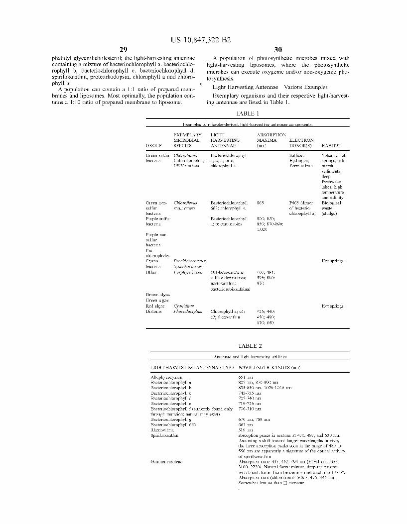
29US 10,847,322 B2
30phaudyl glycerol.cholcstcrol: thc light-harvesung antcnnaccontaitung a mixture of bactcnochlorophyll a, bactcnochlo-rophyll b, bacteriochlorophyll c, bacteriochlorophyll d,spirilloxanthin. proteorhodopsin, chlorophyll a and chloro-phyll b.
A population can contain a 1:1 nhtio ot prepared mens-brancs and hposomcs. Most oplinmlly, thc populalion con-tains a 1 10 ratio of prepared membmne to liposome.
A population of photosyntlmuc mlcrobcs mixed withlight-harvesting liposomes„ (there the photosyntheticnucrobcs can cxccutc oxygenic and/or non-oxygenic pho-tosy'nthcsls.
Light Htuvcsting Antctuuie Venous Exmnplcs
Exemplary organ)sms mtd thmr respective hght-haoest-ing antennae are listed in 1'able 1
TABLE 1
EX) VIPI (Ri'.I()HI ABSOR)'l)OVvll('RO131(I. HAR(ISIIV'G M(X)M( I I H'IRON
GROI P SPECIES AVTENCNAE (run) DONOR(S) HABITAT
Green nonsulfuiba tensPiuplc sulfurba tens
Clt)orvff xiuspp . others
GI'cali 5)dflir GI Iomhrru)r.b:u:tmia C'htnmlicrpetnn,
GSBI. otheis
Bacteno hl» phylla,c d,orccliloiophyu a
B.i tenochlninplnu663 chloroph u a
Baucno lilninphyua, b. cai. tcnnids
865
si!0 820scil 87))-)apt)
1,0 0
Siilfldc.Hydrogen,Fcrrnns iron
P865 (d meinf bactcno-hloropln:lt 5)
Vnlcanic lintsprulR5, 5:utfilarsli
le pli ah;ubk i,hplrernperthuecud s.tin tyB nlog
astelsludgci
If r6.*t r,PmchlorophmesC, aimbr
0th
Pi'cclrlurococcas.
Pr)irma I* Oubt: -,~ t o
51)lf'itc etc)i 'at'c5.nnstoxmthuaba tenonib xsnth ntl
461), 494,96, siin
87ii
Hot spi titn
Bm 5 )Sr
Grccn alaacRcd algae C 'air)if)in)i
D atoms Phrrcui)s r Inru Chlnrophi ll 5. I.. fu oxanth n
425; 44i43) I; 49i671), 6la)
Hot spi'iiig5
TABLE 2
Antennae and I)st)blat esture abilities
I I()HI u LRVFSIING (NI I VVAE IVI'E LV(VI I I M Iu IWV(it 8 ( m)
Auophy o,amnBa teno hloinphyll 5Bacter ochlcicphvll b
Bacteno hloropliyuBactcrio hlnrnpliylt dBt terio hloropliyu e
Bactcrio hlnrnpliylt f icuncntly found onlv
B. I to him ph)u 663Rh lo ib
Sp r tloxanthm
G:unnia- arntenc
6 I run8L» itin. 8 ii) 890 iini8'I 8th run, lim) 1040 nm74 -, 56 ii))1
70 -740 mn719-,"6 nm70D-710 mn
6 0 im, 788 i
rn510 ii
absorpt on peaks ui acct ne at 470 497. and 5'10 runAssum ng a shat round longer wavelengths n io,the three absmpt n peaks seen ui rhe range nf 48LI tn
ii run .ue appsrentlv 5 s goihue f the oph*al 5 I t,of spriruox»itlnnAbs» ption ai:ix. 43 . 462. 494 iun i El%1 mn 2)!"IDD 27201 I aturil fnnn minute, dccp-rcd prisins
iihbi nhluai li r b nrei + Ihu I mp177y"Ab ui In m (Hd»f »1 508 . 475. 446 am
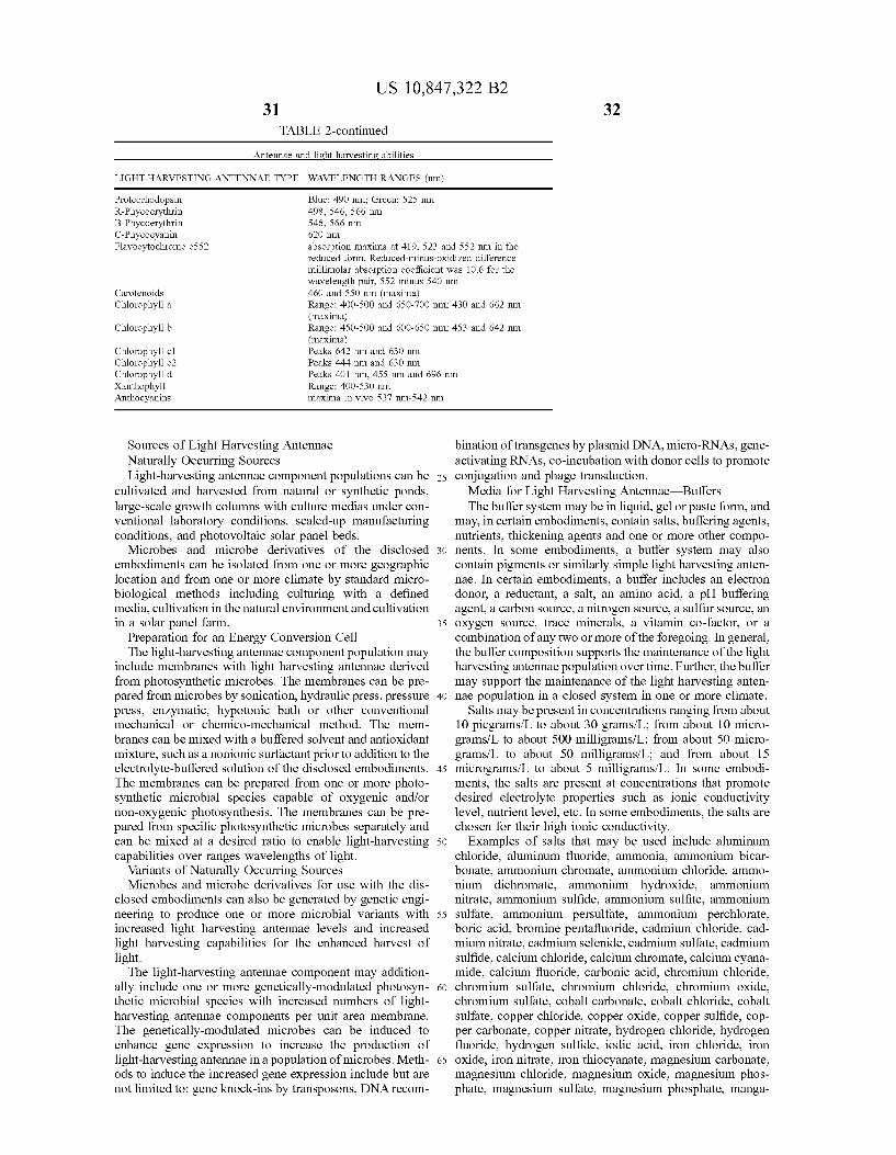
31
US 10,847,322 B232
'I'AI3I.E 2-continued
Ant nnie turd l hthuvesrn ahltes
LIGHT HARVESTING A.JTENNAE TYPE VIAVELENGTH RA.JGES fnml
Prnt nrhodopsin
It Ptn* o(tm
lieve',t brome c((7
nu otenmdsChloioph& ll s
Chloioph& ll b
Ohl »ph& ll el('hl »phyll .'-
Ohl »ph& ll 6Xanthoph, uAil&I&cava&i iis
Blue 490 nax mean . y otn49tl. 46. (66 nm&4(, S(( m
6 omabso&pt on msxnna at 419. (23 and ((2 nm n threduced foim Redu ed m nus ox d xed d aeren enullmolst &bsorpton oefhcent ass n&6 for theu av»length psn. ((2 m mis (40 um46(i s&id " tl iiitl (i&la(tilt&0
Ruire: 400-&00 md 6. (A7(it& nai. 43(i and 66 &uii
tt&1.'i(litle)
Ruigc: 430-&(io mid 60O-mti nni. 4. 3 siid 64 iun
Rmg»: 40u tu iunnisx tnn n voo 37 am (42 mn
Sources of Light Harvcsnng Ante&ulacNaturally Occurring SourcesLight-harvcsuug antennae component populat&ons can be
cultivated and harvested from natural or synthetic ponds,lar e-scale gro&vth colunms with culture medias under con-& t:nlltilydl lilboltltorv Con(hi&Cuss SCIIICd-Up n&BB&lfaCIU&ulg
cond&nous, Bnd photovoltaic solal ptlncl beds.Microbes and microbe derivatives of the disclosed lo
embodiments can be isolated fn&m one or &nore gmigraphiclocation and from one or more climate by standard nucro-biological methods including culturing with 0 definedmedia. cultivation in the natural environment and cultivationin a solar panel farm. 3(
Preparation for au Energy Conversion Celllhc light-harv caUug antenna c componcnl popui el ion may
include membranes with light harvesting antennae denvedfmm photosynthetic microbes. 'I'he membranes can be pre-parR from microbes by sonication. hydraulic press, pressure sopress. enzymatic. hypotonic bath or other conventionalmecharucal or chemico-macha&ucal method. Thc mnn-brancs can bc mixed w&lh a buflhrcd solvent ml(1 ant&oxidmlimixture. such as a uon&omc surf'scient pnor lo addilion Io thcelectrolyte-buffered solution of the disclosed embodinlents.'I'he men&bmnes can be prepared from one or more photo-synthetic microbial species capable of oxygenic and/ornon-oxygenic photosynthesis. The membranes can be pre-pared from spcxilic photosynthetic nucrobcs separately andcml be mixed at a dcs&rcd rano lo enable 1&ght-harvesting o
capabilities over ranges wavelengths of hghl.Variants of Naturally Occurring SourcesMicrobes and microbe derivatives for use with the d&s-
closed embodiments can also be generated by genetic engi-neering to produce one or more microbial variants v.ith o.
increased light harvcsnng anlcnnac levels mid increased1&ghl lrdrvest&ng capab&hncs R&r Ihe enhmlcnl harvest oflight.
'Hie light-harvesting antennae component may addition-ally include one or n&ore genetically-modulated plxitosyn- (othetic microbial spec&es with increased numbers of hght-harvesting antennae components per unit area membrane.Thc gnlclicdlly-modulated microbcs cdn be ulducnl tocnhBnct: gi:ni: expression lo ulcl crise Ihc plodUcno&1 oflight-luiri cating antennae in a popuianon ofmicrobes. Melh- 6(ods to induce the mcreased gene expression include but arenot lin&ited to gene kt&ock-&ns by transposons, DNA reconl-
bulation oftransgenes by plasm&d DNAs m&cro/RNAss cnc-act&vating RNA(, co-incubation v ith donor cells to promoteconjugal&on and phngc Iransduct&on.
Media for I ight liar&eating Antennae 13uffersThe buffer system may be in fiquid„gel or paste form, and
may, in cert&un cmbodmlentb, contain salts, buflhring agents.nulncnm. Iluckcnulg dgnlis dnd onc or morc other compo-nents. In some embodiments, a buffer systeni may alsocontain pigments or similarly simple light harvesting anten-nae In certain embodiments, a bufl'er includes an electrondonor. a reductant, a salt, an amino ac&d. a pH bufferina ent, a carbon source, a nitrogen source„a sulfur cource. anoxy'gcn sources ndcc unlit:ldls. d vltannn 00-faclon 01 acomb&nation ofany Iwo or more of the foregoing. In general,the bufli:r composit&on supports Ihc mau&icnaucc of the lightharvesting antennae population over time I 'urther, the buffermay support the maintenance of the light harvesting anten-nae population in a closed system in one or more climate.
Salts may be present in concentrations ran in from about10 picgramb/L to about 30 grmns/L, I'rom about 10 micro-grams/L 10 about 500 nulligrams/L, from about 50 nucro-grams/L to about 50 milligrams/L: and from about ISnucrograms/I to about S miliigrams/I, In some embodi-ments, the salts are present at concentmstions that promotedes&red electrolyte properties such as ionic conductivitylevel. nutrient leveL etc. In some embodiments. the salts arechosn& fi&r thc&r h&J& iomc conduct&mty.
Examples of salts thai may be uscxf include aluminumchlondc, aluminum fluoridc, lunmonia, ammonium bicar-bonate, ammonium chromate, ammonimn chloride, ammo-nium dichroniate, ammonium hydroxide, mnmoniumnitrate, anunonium sulfide. ammonium sulfite. Bnunoniumsulfate. anunonium persulfate„anmlonium perchlorate,bouc acid, bromule penlafluoride, ctxhn&um chfol&dc, cad-mnun n&traic. cadmium sclnndc, cadmnun sulfate, cddnuumsulfidc, cdlchun chio&&de, cBlc&UB& chrolnaic, cdk:1&un cvslna-nude, calcium fluoride. carbonic ac&d, chromium chloride,cluomium sulfate, chromium chloride, chromium oxide,cluomium sulfate. cobalt carbonate. cobalt chloride. cobaltsulfate. copper chk&ride, copper oxide. copper sulfide. cop-per carbonate. copper ntuaie, hydrogn& chlondcs hydrogenfluondc. hydrogen sullidc. &odm acid, &ron chlondc, &ron
ox&de, &ron n&irate, &ron lluocyanate, n&a@&cs&u&u carbonate,magnesium chloride, nlagnesium oxide, n&agnesium phos-plmte, nlagnesiunl sultate, &na nesiu&n phosphate, lnanga-

33US 10,847,322 B2
34nese oxuhn nuulg&ulcsc stdlB&c, n&Bngancsc chlolxdc, ulan-ganese fh&oride, manganese phosplmte, nickel carbonate,nickel chloride, nickel nitrate, nickel hydn&xide, nickeloxide. nitnc acid. perchloric acid, phosphorus pentabro-mide, phosplx&n&s pentaih&oride, phosphorus pentasulfide,phosplu&rus tribromide. phosphon&s trifiuoride. phosphorustniodide, plaunum chlondc, potassium alumimun fluonde,potassnim borate, potassium bmmidc. potass&um calcn&mchloride, potassimn nitrate, potassium perchlorate. potas-sium pern&anganate, potassium sulfate, potassium sultide, &n
silver chromate, silver nitmte. silver oxide„silver sulfate,silver suliide. sodium aluminate. sodium borare. sod&umbromate, sodium carbonate, sodium chloride. sodium bicar-boruue, sodium hydrosullide, so&hum hydroxxlc, sodnunhypochlonte, so&hum maugan&tc, so&hum nitrate. sodnunnitrite. sodium penodate, sodium persulfate, sodiun& phos-phate, sodium sulfate. sodium sulfide, sodiu&n thiocyanate,sulh&r dioxide, sulfuric acid, tin chloride. titanium chlonde,uranyl carbonate„zinc bromide, zinc carbonate. zinc chlo-ride, zinc fluoride. z&nc iodide. zinc oxide. zinc sulfate, zinc zo
sullidc and others.Nutrients &n thc bufibr are chosen Io mrna&au& a microbial
population In a productive state As examples, the nutrientcomponent may contain all or so&ne of nitrates. n&tntes,ammonia, sulfate. sulfite. phosphate, carbonate, an&innacids. sugars. peptone. casitone. vitamins, minerals. memlsand other components that support microbial grow:th andme&abolism. Nu&nen& couccn&cafions may rm&gc from abou&
30 picgrams/L &o abou& 300 gmms/L, from about I nucro-grams,'I to about 500 milligrams/Ix from about 50 nucro- &c
grams,'I to about 30 nulligmms/I, and from 15 nucro-grams,'I to about 5 milligrams/I
The pigments, if used. may be electron donors nnd/orprovide other roles. They absorb wavelength-specific heftand rcficct or tramm&t light at non-absorbed v,avelcngths. &I
Pigments may cuhaucc 1&ght cncrgy capture. may rcficcthgh& to &he surrounding cnv&ronmen& w itlun Ihe vessel: mayrefiect light to a neighlx&ring light harvesting antennae; mayrefiect light to a neighboring micmbe: may transmit light tothe sum&undin envimnment within the vescek may transmit Bo
li ht to a neighboring light harvesting antennae: may tmns-m&& hght &o a ncighbonug m&crobe: may subtrac& out (Iilter)onc or morc wavcleng&h ranges ol'ght, m&d/or scrvc otherroles. As cxamplcs, pigman&s may be: metal pigments suchas cadmiun&-. chmmiun&-, cobalt-, nickel-. manganese-,iron-. titanium-. zmc-, copper-containing pig&nents and oth-ers; carbon-based pigments such as carbon black, Ivoryblack, and others: cLay earth piguents; ultramarine pig-ments, b&ological organ&c p&gments such as u&d&go, Indianrcxl, Tyrian purple, and others, m&d o&her biolog&c and o
syn&hctic pigments In some cmbod&mcn&s, p&g&uen&s may beabsent fmm the buffer system. In some embodimentx pig-n&eats may be present in concentrations ranging I'ron& about5% to about 90% weight/volume (w/v): ibom abonr 15% toabout 70% (w/v): from about 25% to about 60% (w/v), fmm s.abou& 358io to about 50% (w/v) of Ihe bufii:r system.
11&c bufii:r may Include nutncn&s othcrw&sc tree&ed asw as&c. Onc such cxamplc &s was&cwater. Carbon-contauungcompounds in the wastewater may be used by microbes topn&duce clcctrons. sc
Electron SiphonsElectron siphons may contain electron-acceprin mo&eties
tha& acccp& electrons from o&her anti»cs and transport suchclccxrons by a couduc»ng a&ul/or semi-conductmg structure.Thc clcc&ron s&phons may possess one or morc such elec- sitron-acceptin moiety and may be capable of accepting oneor more electrons concurrently. In certain embodin&ents,
electron s&phons con&a&n membrane dock&ng s&tcs Ibr thcefficient siphoning of electrons from membrane-containingelectron donors. winch may be free ant&trna or part of ano&herstn&cture such as ligi&t harvesting antennae, nucrobes; elec-tron camer pmtc&ns; and other moict&cs &n or gixtaposed tomen&brane of a microbe; a membrane con&ponent, a vesicle;a chloroplast: a mitochondria or other. More generally,electron siplmns may contain moieties to facihtate docking,or simple contact with electron donors of any form.
Thc componen&s of clcc&ron siphous may bc made ofmaterial containing one or more electron carrier proteins,polymers, composites, alloys and mix&urea of carbon, car-bon, silicon, inetals, colloidals, ceramic, copper, zinc. graph-ite, stainless s&ecl, ut;mium oxulc, p&gmenka 1&ght harves&u&g
antennae, chinroplasts, mitochondrim electmn carrier Inol-ecules, other electron recipient n&olecules„and combinationsof any of these In some contexts. the electron s&phons maybe viev ed as both electron acceptors and as electron donors;they d&rect electron from donors in a bufibr toward a currentcollector in a voltaic cell. In some embodiments, the electrons&phons serve as m& elec&ron relay sys&mn betw em»he uuua1electron dnnor and the current collector Iixamples of elec-tron siphon stmctural materials include carbim, electroncarrier proteins, polymers. composites. alloys and mixturesof carbon. silica. metals. pigment~, copper. zinc. stainlesssteel, t&tanium oxide and the like
Electron s&phons may contain amorphous, crysuilline, orpartially crys&allinestructures. Thc s&ruc&urea may have atluckness that is a single atom thick or multiple atoms thickIn son&e embodiments, electron siphons have a unitary ti&rm,
v bile in other embodiments they are assen&bled, and so&ne-
times assembled into a complex. Electron s&phons may beshaped as tube~, wires, spirals, bustles. plates. ~havings,dots. particles, sphcrcs. shee&s. membranes, mesh, webs,nc&works, and &hc 1&kc. Thc electron siphon formals mayinclude a mixed populauon of &wo or morc of thcsc. Fur-thern&ore, each electron siphon may include one or morewire, thread, fiber, tube. dot. plate. particle or other elementcontain&n one or more carbon polymer, metal, metalloid,colloidal or other structure capable of electron transport. Apopulat&on of clue&&on slphons n&av'&elude II populBuon of.tube, w&rc, part&clc. do&, liber, plate, network or o&her.
Mult&pic electron s&phons may bc grouped u& a supcr-stn&cture such as an array, a matrix, a suspension. one ormore layer. a polyn&er, etc. Kith other elements of the voltaiccell such as the bufi'er. the siphons may assume many typesstn&cture such as a gel, a co-polymer. a paste. a semi-solid,and any o&hcr ordcrcd or random arrangcmmu.
Elec&ron s&pho&w have a s&ze appropnatc for Ihcir rule(e g., conduc»ng clcctrons &n &hc cell and/or acccp&u&gelectrons froin donors). Son&etimes, they are sized to inter-face v ith electron donors. In some en&bodiments. thesiphons are on the order of the cell s&ze, or smaller, e, tensof microns dovvn to nanometer scale. In some implementa-t&ons, &hc siphons have an average diamctcr of abmu 1-20&un (c.g. abou& q-5 nm);md an avcragc length ol'bout10-50 um (c.g., abou& 30 um). S&phons ol'lus s&zc can bcarranged on the external surface of a n&icrobe In certaini&nplen&entations emploYing synthetic siphons, the siphonsmay have diameters of about 2-10 nm. Assemblies of suchsiphons may have dimenshu&s of about 50-100 &un.
Exmnplcs of syn&hctic siphons include rccombu&an& p&IA
polymers having q-5 nm diame&cr and 30-80 um lang'&s.Other exmnplcs of syn&heuc siphons Include qum&turn do&s,
quantum &vires. quantum &veils. nanotubes. nanowires, andthe like I iieet&on siphons typically have dimensions on the

3iUS 10,847,322 B2
36order Of ruulomcters, bul other size scales such as microm-eters and millimeters nlay be employed
lixamples stnlctures that can be used for electrml con-ducting nanostnlctures include nanoparticles, nanopolvders,nanotubes. Uanowires„nanorods. nanofibers. quantum dots,dendrimers, nanoclusters. nanocrystals, and nanocornpos-ilcs. Thc structures can bc nuxlc from anv of venousmalenals. Includulg clcclron carrier pmlcms, polymers,composites, carbon (e g, fullerenes), silicon, metal (e g.,copper), nletal alloys (e g, stainless steel), ceramic. titaniunl I o
oxide. etcThe electron siphons may have a uniform or non-unifomt
conlposition. In a purely umfomt embodiment. the electroncdlrylug coulpoucul dud clccfrou dcccplulg clculcul drculluuiucly'uxcd lhIOUgh Ihc siphon. As Bu cxaulph: ol II I
Jlou-uoifol'Iu clccti'on siphon. thc stnlcturc coutallls B coll-ductive rod as a support substrate and be uniformly coatedwith an electron accepting moiety and docking moiety. Inanother example. the docking and/or electron acceptingmoieties may be localized on one side or region of the loconductn c substrate. Such siphon structures may be pro-dUccd bv'u ollcunl lion specific ploccssulg UILcluausul suchas a process that aligns fermmagnetic rods (a collection ofsiphon support stnlcnlres) in a common orientation duriilgapplication of an electroii accepting nloiety and/or dockiilgmoiety.
Electron siphons may contain one or more componentsubulul whcrcby thc component subunit is assmnblcd withdn electron donor. In some cmboduncnls, ml electron siphonsubunit is connected to an electnlu donor. In some embodi- loulclrtx clccll'011 siphon BUbunlts Bl'L connected llrto B nlatitxor other assembly and connected to electron donors In someembodiments, electron siphon subunits are individually con-nected to electron donors, the combination of which maythen bc connected lo other electron slphons. As cxplauxxk isclcctron siphons may contain a conductive or scnu-conduc-tn c material lo lrausport electrons accctltcd or coordulatcdwith another structure of the siphon An electmn siphon mayaccept and coordinate one or more electron simultaneouslyin the presence of an electron donor. An electron siphon may do
donate one or more electron in the presence of an electronacceptor.
lllc propmlsity ol'n electron siphon 10 accept andcoorihndlc onc or morc clcctron may, in part, dclemlincd byIhc potclrtl;ll energy rcqull'cd fof thc clccti'on Bcccptlllg 01'oordinationmoieties to receive an electron from a donor.The electron coordination moieties of the efecuon siphonmay have ovemtll negativity less than the electron donors.Elec Iron elphons may contain overall negativity less 1 lain theclcctron donors and contmn Overall more ncgauv lly llrdn the 0
clcctron BCCLTItors. Exmnples of electron coordination moi-eties include arginine, lyslne, poly-trginine. poly-lyslne,ammonium, tetrabutylammonlum, quinones„ubiquinones,biphenyls. 2.2ubipyndines. azo groups, amine groups. NO,groups, CN ~lups. Baphthalimide, [GO) fuflerenes, poly- ssthiophmles, lcrpyuduic, Inudc groups, polylnndc groups,dcrivatn c tlmreof; or other.
Electron coordulauon moieties may be confugaled toother components of an electmn siphon by various couplingchemistries to yield a covalent bond between the electron iosiplmn and the electron coordination moiety.
Electron siphons may be designed to dock w:ith but notpiercc (Or othcrwisc lyse) microbcs or membranes theyintcrfdcc with. Thc siphons may acl ds bmngn appmldagcsthat siphon electrons gcncratcd metdbohcdlly or photosyn- ssthetically Illectron siphons may contain a coupling moiety.('oupling moieties nlay have an affinity for an electron donor
or a spccics contaimng an electron donor. Examples ofcoupling moieties include antibodies and componentsthereof (e.g., ll(ab) and ll(ab')2 fragntents), protein domains,cholesterol, phosphoinositide, phospholipids. lipid A,lipopolysaccharide, mmman. Iipoarabinomannan, lipote-ichoic acid, pilin, Pills, and the like. In ceitain embodiments,lhc coUphug uiotctu:s dlc coIIIUgdlixl 10 lhc clccfrou siphonal ouc or morc surface residues to enable lonuanon of acovalent bond.
In certain embodiments. to dock with a nlembrane. thesiphon may have a hydrophobic portion I lowever, the entiresiphon structure should not be hydrophobic as this maycause the structure to pierce the membrane. Therefore, incertain embodiments. Onc portion of thc siphon structure ishydrophobic and another portion is nol hydrophobic. Insome implementations, the non-hydrophobic portion of thesiplxou stmcture is charged. either positively char ed ornegatively charged. A positive charge may be employed toattract electrons from the electron transport components inthe membrane to the siphon.
If the base siphon structure is hydroplulic (c.g., metalsiphon structures), it nccd nol bc made posiuvely cliargcd.Instead, a portion is made hydrophoblc to promote mem-brane docking. If the base siphon stmcture is hydrophobic(e g., a carbon siphon stnlctures). it needs no treatment tomal e it hydrophobic. Instead„ it may be treated to make aportion of positively charged.
In certain embodiments. thc ehx tron siphon base structureis treated 10 gnc lf dn Overall positive charge In a neutralbuffer 'I'his may be appropriate when the siphon is hydro-phobic. Iixainples of hydmphobic siphon materials includecarbon (e.g., carbon nanostructures), hydrophobic acrylics,amides. imides, carbonates, dienes. eaters. ethers. fluorocar-bons. olefins, styrenes, vinyl acetals, vinyl chlorides,vlnyhdcnc chlondcs, vinyl eaters. vuiyl clhers, kcloncs,vlnylpyridine polymers and I lnylpyrrohdone polymers.Electron siphon matcnals may bc covalently conpigatcd loac-type cytochrome, arginine. polyarginine, lysine, polyly-sine, pmtamines, histones, iron (III). Iron-sulfur clusters,and the like Electron siphon materials may have theirsurfaces lvith metal moieties such as cadmium, zinc, zirco-ullllu. UiolvbdCUUUI, ulailgailCSIX ulagucslUUJ, uou, plati-num, copper. rhodium, osmium. Indium, and the like. Fur-ther, electron siphon matcnals may have thmr surfacesmodified with other electmn bindiug components having (i)an overall positive charge, (ii) electron-binding capabilities,and (iii) capabiiity of neutralizing the toxic eflects of con-ventional synthetic conductive nlaterials (e ., carbon nano-tubes). Modflicauon ol'ynthetic clcwtron conducuve nmic-rials can be pcrfonucd by conventional chcmmdlconjugation leclunques lncludulg chck chcmislrv andchenlical crosslinking involving mlcleophilic attack andcovalent bond formation benveen the conductive materialand the positiveiy-charged electron binding moiety. Othermethods can include the use of EV irradiation to induceactivation ol a nuclcoplulc lo gcncratea covalent bond 10
form bctwccn thc conductnc matenal and thc posiuvcly-chargcd electron binding momty, also known as photo-crossiinking (ienerafly, Ihe modification covers only a por-tion of the siphon stnicture (e.g, . just an end portion of it)
As mentioned. electron siphons can have a hydrophobicportion to facilitate intemtction with a microbe, microbialmembrane. vcslclc. or other membrane dcnvatlvc contain-iug electron carncr components If lhc base material ls nolhydrophobic, moddicauon must produce a hydrophobicportiml Such hydmphobic portions can be generated by thecovalent coitjugation of stemls such as cholesteml, glycerol-

37US 10,847,322 B2
38c liter lip nl s co iita iiiiiig 1 sopi ciioid cliii itis, cv'ch1pi opaiics Birdcyclohexanes or glycerol-ester lipids such as lipid A, phos-phatindylchohne, phosphatidylethanolamine, phosphatidyl-serine. phosphatidylinositol, sphingomyelin and phospliat-dyl lycerol. Examples of materials that may requirehydrophobic treatment include metal nanostnictures. metal-loidh, colloidals, composite nanostructurcs. hydrophilicpolymers such as polysacchaudcs, polyamiims, protcxtgly-cails, afltlbodies afxl tlie like
In one example, coupling of biologic and biochentical icnioieties to enable electron siphon activity ancgor connec-tivity to one or more electron donor is achieved tluou hacid-activation followed by adding carbodiimide. amidntion,I-ethyl-3-(3-duuclhyhuninopmpyl) carbodiumdc hydro-cldonde, N-hydroxysuccinunnle, or ofter.
In some aspects. a niicrobial cell population is mixed v iththe electron siphon population In some einbodiments, themicrobial cell population may be mixed with the electronsiplmn population at about a I:I ratio; at about a I:2 ratio,at about a I:3 ratio: at about a I:4 ratio; at about a I:5 ratio, icat about a I 6 ratio, at about a I:7 rauo, al a 1.10 ratio andal about B I:30 rano.
In some emlxidinients, a light harvesting antennae popu-lation may be mixed with the electron siphon population Insome embodiments, the light harvesting, antennae populationmay be mixed with the electron siphon population at abouta I:0.5 ratio: at about a I: I mstio: at about a I:2 mtio; at about
I:3 ratio, and at about a I:4 ratio.In some mnbodunmits, thc cleciron siphon population
may be mixed with the microbial cell population and may be icmixed ivith the light harvesting antennae populatimi 'I heli ht harvestin antennae popuLBtion inay contain artificialand/or naturally occurring antennae that absorb light inwavelength ranges that complement the absorprion patternof'thc microbuil cell population. In some embodiments, the iicfccxron siphon population may be mixed with thc microbialcill population and may bc nuxed with hghl harvestingantennae population at about a 0.5 I: I ratio; at about a I I I
ratio: at about a 2 I I ratio; at about a 3 I I ratio; at abouta 4:I:I ratio: at about a 5 I:I mstio: at about a fi:I:I ratio: at soabout a 10: I: I mstio: at about a 15; I: I ratio; at about n30 I: I
raiio; al about a 40.1.1 ratio, at about a 0.5.1.2 ratio, al about1.1:2 ratio; al about a 2 I:2 rauo: at about a 3.1.2 ratio. al
about B 4.1:2 ratio, at about a 5.1.2 ratio. at about a 6 1.2ratio; at about a 10 I 2 ratio; at about a 15 I 2 ratio: at abouta 30 I 2 ratio, at alxiut a 40: I 2 ratio: at about a 0 5 I 3 ratio,at about a I:I:3 ratio: at about a 2:I:3 ratio: at about a 3 I:3ratio; at about a 4: I:3 mtio; at about a 5:I:3 ratio: at abouta 6.1:3 ratio: at about a 10.1:3 ratio: al about a 15:1.3 ratio,at about a 30.1.3 ratio, at about a 40.1:3 rauo. at abuut a c
0.5.1.4 ratio, al about a 1.1:4 ratio: Bl abuul a 2.1.4 ratio. alabout a 3:I:4 nstio, at about a 4 I 4 nstio; at about a 5 I 4ratio: at alxiut a 6 I:4 ratio: at about a 10 I:4 ratio: at abouta 15: I;4 ratio; at about a 30: I:4 ratio: at about a 40: I:4 ratio,at about a 0.5;I:4 mstio, at about a I;I:4 ratio: atnbout a 2 I:4 11
ratio; al about a 3 I 4 ratio, at about B 4.1.4 ratio; at about5.1.4 ratio: at about a 6.1:4 ratio, al about a 10.1:4 ratio,
Bt about B 15 I 4 ratio, al about a 30.1:4 ratio. Bl about a40 I 4 ratio; at about a 0 5 I 5 ratio; at about a I I:5 ratio,at about a 2 I:5 ratio; at about a 3:I 5 ratio; at about a 4 I 5 icratio; at about a 5: I;5 mtio; at about a 6:I:3 ratio: at abouta 10: I: 5 ratio: at about a 15: I 5 ratio; at about a 30: I:5 ratio,al about a 40.1:S ratio: al about a 1.1:S ratio, al aboul a 2 1.5ratio: at about a 3.1.5 ratio, at about a 4.1.S ratio: at abouta 5.1.5 rauo; at about a 6 I: S ratio, Bl about a 10.1:5 ratio, siat shorn a 15 I 5 ratio, at about a 30 I:5 nstio; at about a40 I 5 mtio: at about a I I 6 ratio; at about a 2: I 6 ratio; at
about a 3:I:6 ratio, nt about a 4 1.6 rauo: at about a 5.1:Gratio: at about a 6:I:6 ratio: at about a 10:I:6 ratio: at abouta 15: I 6 ratio, al about a 30: I:6 ratio, at about a 40: I.G ratio,at about a 2: I 7 ratio; at about a 3:I 7 ratio: at about a 4 I:7ratio, at about a 5.1:7 ratio, at about a 6.1:7 ratio, at abouta 10: I 7 ratio; at about a 15: I:7 ratio; at about a 30: I 7 nstio;at about a 40: I:7 ratio: at about a 2: I:8 mstio: at about a 3:I:8nstio; at about a -1 I:8 ratio; at about a 5 I:8 ratio; at abouta 6:I:8 ratio: at about a 10:I:8 ratio: at about a 15:I:8 ratio;al about a 30.1:8 ratio. at about a 40.1.8 rauo: at about a
2:I:9 ratio; at about a 3:I;9 ratio: at about a 4:I:9 mstio: atabout a 5.1.9 ratio; at about a 6: I 9 ratio: at about a 10.1:9matin; at about a 15 I 9 ratio; at about a 30 I: 9 ratio; at alxiuta 40: I 9 ratio, al about a 2.1:10 ratio, at about a 3:1.10 ratio,at about a 4 I:10 ratio: at about a 5 I 10 ratio: at about a6: I:10 ratio: at about a 10: I:10 ratio: at about a 15: I:10 ratio;at about a 30 I 10 ratio: at about a 40 I:10 ratio; and up toabout a 40:I;20 ratio.
Thc clcclron siphons may bc positioned ihrcctly adjacentto the light-harvestin antennae component of the disclosedembodiments. Further. lhc clcctron siphons of the dtscioscxfembodinients can be positioned directly adjacent to anelectron carrier component for the scavenging of free elec-trons generated by photon-mediated excitement of the light-harvesting antennae component popuLation. Electronsiphons can be positioned alon the surface of a microbe. amicrobe-dcuved mcmbranc component or a vewclc withmubcddcd light-hats eating antciuiac componmils.
'I'he above treatments modify the electron siphons in amanner to maintain the photo-activity of a microbe iii'ucrobe-derivedmembrane component when positioneddirectly adjacently (i.e., docked, buned or bound (e, in anantibody-antigen imnnme complex) or other). Further, themetabolic activity of a microbe mid llm electron tmnsporlcapabilitms of elccuon carrier components in a microbialmembrane may be prcsctv cd when such clcctron siphons aredocked
liurther, disclosed is a bio-safe niodihed nanostnictureunit for electron scavenging directly from a light-harvestingantennae component to enable directional electron flowacross a nano-scale unit. Further disclosed is a populauon ofthc bio-sage modtficxl nano-scale units for chwtron scavcng-iug directly from a light-Iuirscsling anterurac componentpopulation to enable directional electron flow across thepopulation of modified nano-scale components
In some embodiments, electron siphons may include anelectncafly conductin or semi-conductin matenal linked(e g., covalently) lo posiiively-charged clcctron acceptormolcculcs capable of'ontacting a microbial membranehaving one or morc hghl harvesung anterurac Thc posi-tively-charged electron acceptor niolecules of the disclosedembodinients may include arginine, lysine, poly-arginine,poly-lysine, thermo-stable electmn carrier protein or deriva-tive thereof, or other.
Thc vessel can bc Ihbncated in a maiuicr to generate a
layer of light-harvesting antennae component populationjuxtaposed to thc glass panel. wluch is fuxtaposcd lo a layerof modified conductive nano-scale coniponents. which isjuxtaposed to the electron tloiv conduit plate, which isjuxtaposed to the insulating injection-molded polymericside-wall and backing unit. The modified conductive nano-scalc components can apply to thc clcctron flow conduitplate by spraying, rolling, and printing. In some embodi-ments, applying a prc-Boxed soluuon includes: a lighl-harvesting antennae component population and a modifiedcmiductive nano-scale components, where the solution is the

39US 10,847,322 B2
40pH-bufli:rcd clcmtrolyte solution of Ihe disclosed embodi-ments directly to the electron tiow conduit plate of a lmhtconversion systenl
A light-conversion systenl of an embodiment includestempered glass top plate (FICi. 3, 1002) built to withstandlarge tenlperature msnges and optimized for lighr penerrationw iih nuiumal rclractivc properties, onc or more UV-rcsistmligasket (1003) to generate a leak-pruol sealant around the
lass top io prevent loss of the electrolyte-butTered solution(1004): a light-harvesting antennae coinponent population in in
an orientation to nlaxinlize light-absorptive etficiency(1005): that are juxtaposed to a layer of conductive nano-material (1006) to maximize photon-excited electron scav-mtging and luiulelutg away Irom Ihe light-luirvesung anten-nae population towards a conducuve bark-plate (c.g, acurrent collector), which then directs current to an externalcircuit (1007) In the depicted embodiinent, a major portionof the light conversion systenl has an enclosure of injection-molded polymeric insulating side walls and backin fmrne(1008) containing one or more access port to enable access Io10 ihC CICCII CIVIC bUflbr Soltnloll. light-lulrvCStlllg iillicllllaCcomponent population and conductive nano-scale compo-nents contained within the insulating walls.
Additionally. presented herein is the use of bio-safenlodihed nano-scale components (ltlii 4, 2002) to scavengethe excited electrons genemsted from fiptt-mediated electronexcitation on a light-harvesting antennae molecule tluou hIhc dllcci cilllidct ol illc llano-scdlc'. colupoucum 10 thclight-hart eating antcturdc component populauon (2003)
In some embodiments, microbes may be selected to lopossess or mduced to create electron conducting nanostruc-tures 10 renlove excess electrons (pnlduced plxltosyntheti-cally or metabolically). Such structures are anatomicalextensions of microbes. Such structures can be: fibrils. plh,accretion systems (types I, 11, HI, mid IV) and exosomes. IsColupiÃltliluS Ol 9Uch SIUICIIIICS Call lllChidC plolclll, pro-tcoglycan. hposomnl, llpopolysacchandc. In ccrlmnembodiments. such nlicnlbial nanostnictures couple directlyto an electronically conductive anode oi'iulductive networkattached to the anode. The structures can be induced by do
adding: exposure to light (increased intensity, tluou hICIISCS). CXp09UIC 10 IIUillCIlm 01 tipleglilduou 01 IEC gcuCSmtcodulg the eue products involved in gcncraiutg thcdlldiolulCdl CXICIISlotls IhrOUgll gcllCIIC Cllglllcellllgapproaches.
I ilectron Siphon MatrixIn some embodiments. a voltaic cell may contain one or
more electron siphon matrixes. A matrix may contain anarray of electron siphon subunlis arranged ulto a network orpolymer. Tlm network or polymeric mduix may be fabn- o
cd(ed Ilu ough Ihc covalent couphng ol subumm Imd throughthe electrostatic intemsction of subunits.
In some enlbodinlents. a microbial cell population lsdirectly conjugated to the electron siphon matrix. In someenlbodiments. a micmbial cell population is directly 19
absorbcxf onto thc electron siphon matrix. In some embodl-Iuclus. d light halvcstltlg Butcllluic'. popUlauou ls illlcctlvconjugated to thc electron siphon matrix. In some embodi-ment~. a light harvesting antennae population is directlyabsorbed onto the electron siphon matrix In some embodi- ioments, a microbial cell population and a list harvestingantennae population are directlv conjugated to the electronsiplxln matnx. In some embodiments. a nncrobial cellpopulation and u light harvcsung anieiulac population areabsorbtxf Io the electron siphon matnx. ss
In sonic embodiments, an additioiml electron conductivenlaterial is directly conjugated to the electron siphon ntatrix.
In some embodimcnis. electron conductive nuiterial isdirectly absorbed to the electron siphon matrix In soineembodiments, electron conductive material is separatedfrom the electmn siphon matrix by a semi-permeable barrier
Electron Siphon and Voltaic Cell Armsn ementsArrangement l. Electron Siphons and Electron Donor
Population ArrangcmennIll sonic cxiiulplcs. clcctrou9 orlgltlBilllg front lllclllbcrs ol
the electmn donor population in a voltaic cell may be excitedinto a lngher energy state by photon energy passage into thevoltaic cell In some exiunPle. electrons originating frommembers of the electron donor population in a voltaic cellmay be generated by the hydrolysis of covalent bond energytu 9 blochclulcal Icdciloll. Ill silluc cxtilllplcs, Ihc c'lcclroudonor population may coniaul light harvcsuug antennae. Insome exmnples, the electron donor population may containpigments In some examples. Ihe electron donor popukstionmay contain microbial cells. Iilectmn(s) originating frommembers of the electron donor population (FICiS. 6, 601 to611) may be captured by members of the electron siphonpopulation (FIG. 6, 612). lite electron siphon populationchiulncls clcctrons toward a current collector or ehmtroni-cally conductive portion of the voltaic cell, which pmvidesthe electrmls to an external load. I ilectrons captured from theelectron donor population tloiv m a direction (ill(i. 6, 613)The direction of electron floiv, also referred to as a current,may be established within a voltaic cell by an electricalpotmliial dilfcrcnce gcncrdicd spontaneously witlun Ihe vul-taic cell and may be optionally facilitated by ml cxiemaldevice establishing polarity within the voltaic cell '1 hedirection of current may be generated, in part, by thearrangement of electron siphon population in the voltaiccell. Direction of the current may further be influenced by anapplied electrical potential across a voltaic cell. Electronslphons may bc arranged ul a minuter whereby variouselectron slphons may directly connect a second clcctronsiphon mid whereby a lira( clcctron siphon may accept anelectron froin an electmn donor and whereby a secondelectron siphon may be connected to a second electronup llo11.
Arrangement 2. A Second Arrangement of ElectronSiphons and Microbial Cell Population.
Ill sonic cxaluplcs. a 91luphc Strati'tllcut of 9 ullxitilc ofelectron siphoim (FIG. 7. '706) mid a mixture of mcmbcrs ofthe electron donor population (liliiS 7. 701 to 705) may beplaced in a voltaic cell I ilectmn donors of the electron donorpopulation may contain microbes. pigments, li ht harvestinantennae or other. Electmn siphons of the electron siphonpopUIBiloll uuiy'oluaul colulUcilvc lltiuopdrilclcg colldilc-tlvc uanowircs. conductive nanotubcs, conductive mesh,conductive plate. Bttd/or other elements Electrons gcncraicxfby the electron donor may be siphoned by the electronsiphon through a tmnster eveltt of the electron from thedonor to the siphon (may also be an intermediate electronrecipient). Electron siphons may be arranged tn a mannerwhereby venous electron slphons may bearrangcd Iuxta-poscd Io one or morc electron donor. Electron siphons maybc arranged in a manner whereby onc or morc electronsiplxm nlay directly coilnect one or iuore electron donor andaccept an electron tronl the electroil doilor One or moreelectron donors serve as nodes or path elements in anelectron conductive pathway from donors to a current col-lcc lot ol B vol(die cell.
Arrangemcni 3. Arrangemcnts ol'cvcml ElccuonSlphons.
In some examples, a polynler of carbon (IT(i 8 (A-( ))may be the conductive material in an electmn siphon 'I'his

41
US 10,847,322 B242
form of carbon polymer may conuiin a sheet, mcmbranc,mesh. plate, fiber, tube, wire, dot, particle or other. In someexamples, an electron siphon may contain a nanotube. ananolvire. a nanohber, a nanoparticle or other (IIIC). 8A,802). In some examples. an electron siphon may contain ahollow nibe. a wire. a fibril, a fiber. a braid or other (FICi.8B). In sonn: examples, an clectmn siphon may contaul a
dot, nanopalticlc, mlcroparticlc. sphere, spheroid. polyhc-dmn, a hollow polyhedron or other (lq(i. 8G) Moditicationof ihe electron siphons may be made using conventional 10
activation techniques such as acid activation, which maygenemte reactive chemical moieties on one or more residueof the electron siphon. Additional modifications may begcncratcd in the prcscncc of NHS, sullb-NHS. EDC. BMPHol othcl llnkcrs. I
Arrangement 4 Varied Army of lilectron SiplmnsI ilectron siphons may be conductive or semi-conductive
ill llatlll'C alai inay'C BtvallgCd ill a iu;lllilel'o pl'ililliltC thCtravel of electron from one end of the array to the other.Arrangement of electron siphons may be manipulated by 10
natural propcrtws such as tfian der Waals forces or may bemampulatcd by synthetic mcmls such as covalent couplingof electron siphons into an array In one example, a homo-eneous collection of electnim siphons (I'l(i 9A, 9tH) may
be arrayed. Ivhereby an electron siphon (901) may be incontact with a second electron siphon in the array (903). Incertain embodiments„ the electron siphons conmin modlfi-cauons (902) to promote a linkage between ad)scent cloctronsiphons in the array, to promote the transport ol electrons, topmmote docking to an electron donor, to serve as a docking 10
site tier electron conductive material or other Sometimes,the links e is on the order of about 0 to 2 Angstronls Inanother example, a heterogeneous array of electron siphons(FICi. 9B. 905) is arrayed in a manner whereby an electronsiplxin type (901) havulg distinct electron siphon propctt tea limay bc combined with a sixond electron siphon type (904)havulg ihficlcllt elec)roll slp11011 plopc'rfics to clu:riitc Buarray of electmn siphons which promote the etfective accep-tance and transfer of electrons fmm a hetenlgeneous elec-tron donor population. These types of arrays mny serve sovarious functions and depend on the presence of variousmodilicaiions. In some examples, modilications may conlmndirect conjugation. of a positively cliargcd moiety such asbut not limited to a positively cliargcd anuno acid. cationiclipid, cation. or other, of a neutrally charged moiety such asbut not limited to hydrophobic agents, gwitterions or other,ofdipolar molecules such as nitrones, 1,2-dipole. I.g-dipole,amine oxides or others: of binding molecules such. asantibodies. rcceptors, llgands, NAD+, NADP+, FAD. FMN,FcS clusters. hcmc, cocnzyme Q or others, and oi'cnzymcs 0
such as thc oxygen-evolving complex, oxidorcductasc, orother.
Armngements 5 Hse of )ilectron Siphon to (:aptureElectrons Cienemted fmm Metabolic Processes.
The movement of iona across a membrane depends on 11
two factors. (I) thc dill'uslon lbrcc cmised by im establishedCOIICCII)ra)1011 gladlCnt Of CIICIIIICBI Spc'CICS. 111Chidulg lolls,and (ii) dlc clcctrostatic force. caused by thc electricalpotential radient, lvhereby cations (fiir exainple. protons(I I+)) difFuse down the electrical potential and anions (for ii!
example. OH ) tend to diifuse in the opposite direction.These tlvo gradients taken to ether may be expressed as anc)ccxrochcmical gradient. In blolo ucal cells and liposomcsthc lipnl layer may act as a barner for ion passage. Potentialcncrgy may result from thc buildup of an clcctrochcmical sidi tferential across a lipid layer and this energy may be storedfor use. In biological cellular membranes. protons tkiv ul an
acuvc transport manner to sct up a pH and clcctnc char cditferential across a membrane. It may be descnbed as themeasure of the potential energy stored as a combination ofpmton and voltage gradients acmss a nlembrane (difigrencesin proton concentration and electrical potential). The elec-tncal radient is a consequence of the charge separationacross thc mcmbrimc (when the protons H move without acountcrion, such as chloride Cl ) In biological systems, thcelectrocheinical gradient often serves as the proton motiveforce (PMF)
In some examples, an electron donor is a nlicrobial cellUsually of a microbial cell, a PMF ls generated by anelectron transport chain in the microbial cell membmne(FIG. 5). wluch acts as a proton pump, using thc cncrgy ofelectrons from an oxidation cvmlt of a rcduccd electroncarrier (ligi. 5) generating an oxidized electron carrier (I'l(iIUA, 1004) to pump pmtons (hydmgen ions, ill(i. It)A,IUU6) out across the membrane into the envimnnlent (I'l(i10.A. enlironmental electron. 1009; environment. 1007),separating the char es across the membmne to generate adistinct clcctron (1005), which may rc-miter thc microbialcell (1008) ulto thc cell for cncrgctic reactions (1002).
In some exanlples. an electron donor is a mitochondria,and ener v released by ihe electron transport chain is usedto move protons fmm the mitochondrial nlatrix to theinter-membrane space of the mitochondrion. Movin theprotons out of the mitoclmndrion creates a lower concen-tration of positively charged protons inside it, rcsultulg in aslighl negative charge on thc ulsidc of Ihc mcmbrmlc. Thcelectrical potential gradient is about — 170 mxf In mitochon-dria, the PMF is alnlost entirely made up of the electricalcomponent, but in chlomplasts, the PMII is nlade up mostlyof the pH gradient because the charge of protons H'sneutralized by the movenlent of Cl and other anions. Ineither case, thc PMF must be about 50 k)/mol lbr thc ATPsynthasc to make ATP.
In onc cxamplc, ml ehxuon siphon (FICi 10B. 1010) maycmltact the exterior surface of a menlbrane hosting anelectron transport chain (I'ICi IUD, IUUI) 'I'he electrontransport chain is fed electrons and pmtons from biochemi-cal and/or photochemical reactions by reduced electroncarriers (FIG. IUB, 1003), which may bc oxnlizcd (1004) bymembers of the elccuon transport chain in thc membrane.Thc SCTIaration of the electron (1005) lbom the proton (1006)may occur in an intra-nlembrane manner. 'I he proton may beexpelled (I U09) in a conventional manner into the envimn-ment (1007). The electron (1011) may be captured by anelectron siphon (1010) when the electron siphon may benext lo, ul contact with, may bc covalently lurked to or maybc cmbcddcd uitlun thc mmnbrane (1001).
Arrangemcnt 6. Usc of Electron Siphon to Capture Elec-trons (ienerated from l.iposomes.
A hght-harvesting liposome containing light harvestingagents such as pigments, light harvesting antennae, andreduced and oxidized electmn carriers, respectively (FICi.11A, 1103 and 1104) on thc ulsidc ol'hc llposomc andconlponcnm of Bn clcctloll tliulspiiit chain lu thc hposonlcmembrane (FIG. 11A, 1101) may serve as ml electron donor.('apture of light energy and subsequent tmnslation of theenergy into the form of a high ener y electmn may enablethe electron to be captured by an electron carrier (FICi. 11A,1103)„which may then transfer the electron to the electrontransport chain (FIG. 11A, 1101) to rcgcncratc an oxtdizcx)electron earner (FIG. 11A. 1104). The agents of thc clcctrontransport chain may bc capable of separaung a proton (FIG.IIA, 1106) and an electmn (ill(i. 11A, Ill)5) Under thesecmlditions, the liposome nlay not transnlit an electron to the

43US 10,847,322 B2
44mivironmcnt (Flfi. 11A, 1108) and the electron will bcdirected intravesicularly In the presence nf an electronsiphon (I'IG. I II3, 1110) niay contact the exterior surface ofa liposomal niembrane containing an electron transpnrtchain (FIG. 11B„1101) The electron siphon may be used tore-direct the path of the electron in an electron rmnsportcluim;md may promote capture of the electron (Flfi 11B,1111).
Armngement 7 Side View of a Voltaic CellIn this example, a voltaic cell includes a vessel (IIICI. 12, io
1201) containing an electnm conductive material (1202) onone or more surfaces of the vessel. The vessel mny furthercontain a semi-permeable membrane (1203) to serve ns adiscrmurmtivc burner bc(ween the electron conducIivcmatcndl (1202) and n ddlhrcnt clcctron conductn e matcnalcapable of contacting one or more electron donor (1206) Aspace (1207) ranging fmm 2 Angstroms to 50 cm may existbetiveen the semi-permeable niembrane (1202) and a currentcollector (1204) Electmnically conductive features pen-etrate space (1207) to permit conduction of electrons from Iomcmbranc (1202) to current collecior (1204). A bulli:r orother tonically conducnve medium may bc presmi! in thespace 'I'he vessel may further include an arrangenient ofelectron siphons (1205) which may contact electron donorsand may contact a bufFer system (12(fg)
Arrangement 8 Voltaic Cell Tube.In one example. a Iiexible transparent tube (FIG. 13,
1301) nuiy contain a voltaic cell (1302) contmmn cloctronconducuie matcnal (1304) that may bc sepamtod by asemi-permeable nienibrane (13(0) fmin the electmn donor iopopulation (1305) to genemte a chemoelectric potentialacross a membrane In this embodiment. the tube serves asthe voltaic cell vessel nnd serves as a conduit for ilov.ingbutfer solution. The tubular vessel may be wrapped orolhcrwisc conformed to Ihc shape of a pole or oIhcr structure iidssocldtcd vi(11 tile voltaic cell.
Arrangemcnt 9. Voltaic Cell Pillars.In this exaniple. voltaic cells (lil(i. 14, 1402) are arranged
on an electnm conductive base (1401) 'I he voltaic cells mayeach include a tmnsparent vessel, each vessel in n pillar or do
other vertical stnicture. Each vessel may contain electrondonor population (1406) nuxcd with dn ehxtron siphondrrmigmncnt (1405) surrounding the electron conductivematcndl (1403). There may bc a semi-pcnnmible mcmbranc(1404) surrounding the electron conductive material (1403 )to promote an chenloelectric potential acniss a menibrane
Arrangement 10. Arrangement of Circuit Connectivity ina Voltaic Cell
In one cxamplc, n voltaic cell may con(am an electronconductnc matenul (nlso refcrrcd as a cathode) (FIG 15, o
1503). The cathode may be connected to an clcctriiii coil-ductive wire lead (1507) I'he cathode may be coated by asemi-permeable membrane (1302) to generate charge sepa-ration benveen a second electron conductive material (re-ferred as an anode) (1501). In this example, the electron i.siphon population (1505) may bc arranged to contact thcanode (1501) and may scrvc as an uiterfacc with the cloctrondonor population (1504) to harvest clecInms (rom the donorpopulation and transniit the electrons tn the anode 'theelectrons niay then tmvel into a second conductive v ire io(1506) and eventually into the grid.
Arrangement 11. Arrangement of Electron Donors onElccuon Siphons in a Parallel Minuter
In onc example. electron donors (FIG. 16, 1605) may bedocked (1606) at an electron siphon arrmigmnent (1601). Si
Docking may contain a covalent bond fiinnation, atfinityniediated interaction (fiir example, antibody-ligand dnven
afgntty, hydrophobic-hydrophobic interaction, or other), orother lilectron tiow from an electron donor (1605) inaytravel frmn the donor to the electmn siphon (1601) andtowards conductive electron material in a voltaic cell
In one example, more than one electron donor (1605 and1607) may be docked at an electron siphon arrangement(1602). Docking may bc mediated by oue or morc manner(1606 and 1605). Elccuon liow muy occur Ibom eachelectron donnr onto the electron siphon arrangement (1602)and towards conductive electron material in a voltaic cell.
In one example. more than one docking site (1610) mayexist between an electron donor (1609) and an electronsiphon arrangement (1603). Electmn I)ow may occur fromthc electron donor through more than ouc docking site to thcelectron siphon arrimgcment.
In one exainple, more than nne electron donor may bedocked at an electron siphnn armngement (1604) ln thisexaniple, electron donors (1611 and 1612) may be docked bymore than one method and niny transfer electrons to thesame electron siplmn arrangement in a manner parallel innature, with electron (low ui onc ihrection (1613) on theCICC(roti Slplloti atrdllgCIIICIII.
A docked arrangement of the electron donors at more thanone point along the surface of an electron siphim arrange-ment enables increased electron harvest and may causeincreased eiectron flow (also known as current). Thisexample describes the design of a parallel element to be usediu a circuit Io gcncratc increased current.
Arrangement 12. Arrangcmcnt of Voltaic Cells ui Sencs.'I'he arrangement of voltaic cells in a senes may increase
the voltage and the current disproportionately. In thisarrangement, a panel (FI(i 17. 1701) may contain variousvoltaic cells (1702), each having n cathodic wire (1706) andan anodic vvire (1705) to connect it to a grid of cathode(1704) and anode (1703), respectively. Thc panel maycontaui an array of cathodes and miodcs and may bc cun-nixtcd to a master cathodic wire (1707) and master anodicwire (17(f 8, respectively.
Arrangeinent 13 Voltaic Panel and a Battery.In this arrangement. a voltaic panel (FICi 18, 1801) may
be connected to the grid (1804) nnd may also be connectedtluough wires (1803) to n bauery (1802). Iu some examples.thc bat(cry is servuig as an external polnnty-generatuigagmi( whcrcby thc polarity of the voltaic panel nmy bcdeternnned by from the positive and negative electrodes ofthe battery leading to the voltaic panel. 'I'he applied potentialmay activate or enhance the activity certain microbes, lightharvesting antennae. or other component of the voltaic cell.In some examples, cxccss power generated from thc voltmcpanel may bc stored in thc baucry.
AIIilllgCIIICIII 14 IIIIIIICISIblc Vol(SIC Cell.An immersible voltaic device for water-derived electricity
may include two electmdes cnnnected through a load andhaving ditferent electrochemical potentials when inunersed.In some exampies, the device may be fully immersed in abody of water. In other cxmnples, a portion ol'hc devicemay bc immersed ui a body of water. Examples ol'bodies ofwater may include pools. ponds, lakes. streams. nvers, bays.oceans or manmade watetways.
In sonic embodiments, a voltaic cell fiir electricity gen-emtion ui a body of water includes tv o electrodes, oneelectrode having a semi-permeable membrane surroundinthe clectrodc to prevent nncrobcs from contactuig the elec-trode but allow ious to pass. The membrane may haveanOVCrdll IICillldl Ol Sllgllt ClidlgC dlld llldy'cpcl CICC(IOIIS
and/or aninns of the surrounding medium fmm one elec-trode 1)ie membrane may also have a pore diameter of less
US 10,847,322 B24i
than or equal to about 0.22 um. Examples oi'cmbrancmaterials include polypropylene. nylon, silica. or other.Membmnes may be directly attached to the surface of theelectrode or may be in a cage surrounding the electrode
Electrodes may include solid or semi-solid forms and maybe structured as plates. mesh. lattices, bristles. foams, clus-ters, emulsions or other. Electrode surfaces may be flal,sl&pplcd. rounded, c&roam(Orcut&Bi, asynunctucal or other.
In some enibodinients. electrodes may be arranged in aspatially separated manner having about ]0 Angstroms to &0
about 10 mm of separation between the electrodes. In otherentbodiments. electrodes may be arranged in a spatiallyseparated manner having about 10 nun to about 0.5 m ofspace bctw cen Ihc elcclrodcs. In ycl other cmbod&ments. thcclcclrodcs may bc spat&ally separated from about 0.5 m toabout 2 m. In sonic enibodiments. the electrodes may befixed to a stationary surface In other emlx&diments. theelectrodes niay be tethered by wire or other conductivematerial and may be moveable in an aqueous enviro&unent.
In another form, one electrode contacts a popufistion of 10
clcmron s&phons. Somcl&mcs, lhc cleclron siplx&ns areattached lo Ihc clcctrodc by covalent, cleclroslal&c or otherforce 'I'he electron s&phons may be arranged in a collectionprior to attachment to an electmde surface or arrangeddirectly onto a surface In some e&nbodi&nents, electronsiphons may be coated onto an electrode surface. Coatingsmay be regularly or irregularly deposited. Electron siphoncoatu&gs may bc scqucnt&ally applied, whcrcby, a Iirst layerof clccuon siphons may be apphcd and a second layer ofdifferent electron siphons may be applied ln some embodi- &o
nlclrtx '10 electrode surface is modified. In some embodi-nlclrtx Bn electmde surface is modified I ilectmdes may hrstbe treated prior to electron siphon attacluuent. Treatmentsmay include acid treatment. thermal treatment, oxidizingchemical Ireauncnt or other. In some embod&ments, an 11
clcmrode surface muy be treated w&th about 1-500 mM HCI,perchlorm ac&d, form&c ac&d. acetic seal or otlmr. In someembodimeiits. an electmde surface niay be treated ivith heat.in other embodiments, an electrode surface may be treated&vith hydro en pemxide, superoxide, hydroxide bases. and do
other chemical capable of oxidizing an electrode surface.Dcs&rcd irealmenls do uot &ntcmipt thc elcclncal conduc!iondb&hl&cs of Ihc electrode.
One purpose ol electrode surlace Irealmenl is lo encratcreactive groups for attachment of electron siplxoas.I:xamples of reactive groups on an electrode surface thatmay be compatible for attachment of electron siphonsinclude OH„SH, S 0, epoxides, COOH. C 0,
H. NH, NHS, NH2. NH3, asides, thiorobcn-zcncs. Bn&des. and others In some cmbodnuenls. Bllacluncul 0
ol'electron s&phone to a treated electrode surlace may occurthrough van der Waals forces, electmstatic forces or cova-lent bonds. In some other embodiments, attachment niay befacilitated by a comb&nation of bonding and forces. Follow-ing treatntent of an electmde surface. a second treatment of 11
Ihe clcclrodc surface may bc pcrlomicd lo gc&mralc covalm&ldlt&&Chil&C&ll nion:t&CS Bs ilcedCd &0 fur&i&CI fBC&h&BIC ch:Clio&1
siphon auaciunm&t by covalent bonding.lilectron siphons may mclude aromatic amino acids,
benzenes. posit&vely charged amino acids„phenolic cont- iopounds, aromatic compounds, iron-sulh&r clusters. caroti-noids, pigments, proteins, protein filaments and others.Elcclron s&phons may also u&elude a slniclured arrangemculincludmg grapheme, carbon, menil. mclalloul, composite,colloids. or other. In some examples. clecuon s&phons may sibe niodihed. Modification of electron siphons may includethe attachment of one or more additional electron siphon In
46some cxamplcs. modilicauon to clcctron s&phone may occurprior to their arran ement in a voltaic cell. In otherI x la&plea, clccl&on siphon alod&ficdhon il&ay oci Ul Iollow Bigtheir 'ilr'ingcn&ent nl,'I voltaic cell
In onc ex&BI&pic, II portion of a prc-dirangcnicnl ofclcclronsiphons may be activated and niodified with aromatic aminoacids. phenyialanine, tryptophan. tyrosine or other. Inam&ther example, a portion of a pre-arrangenient of electronsiphons may be activated and mod&fied w&th pigments. Induo&bc& casu&pic, B porhon ol II prc-Br&dngcn&cnl of electronsiphons may be activated and modified with PIIA. c-typecylochromcs. Omcg and others.
lilectrodes modified ivith electron siphons may harvestelectrons Ibom bod&cs ol'water contuu»ng m&crobcs. Emer-sion of the electrodes into the water can generate measurablecurrent. Increased current may be generated with an elec-trode modified with electron siphons Using electron siphonsserve multiple purposes: (i) they may Increase the surfacedrca 01 thc clccnodc, (0) llicv'lav'rovah: B s&lc 01 conlaclwith a microbe in the body of water, (iii) they may providea s&tc of elcclmn harvesluig. (iv) they may prov&dc a Ilucedimensional surface to interface with a dynamic fluid. (v)they may scrvc as a solid surface of unpucl when a mechiuu-cal fi&rce is applied, or other.
A moving body Of water contuuung m&cmbcs mayincrease the collision frequency between a micmb&al surfaceand an electrode. An electrode conta&ning electron siphonsmay further increase the surface area and thus increase thenumber of collisions that can occur benveen microbes andan chmtrodc. Optimal number, arrangcmcnt m&d composit&onof electron siphons on an electrode may further increase theelectron transfi:r Ibom thc mmubraue of m& aquatic m&crobeto the surface of the electrode Iixamples of moving bodiesof water include oceans. lakes. ponds, streams, and nvcrs.and man-&nade &cater&rays such as dams, viaducts, aque-ducts. canals. or other.
In one exa&nple, a voltaic cell includes 2 electrodes, oneof wh&ch is coated &vith a semi-permeable membrane. themembrane of which luis an exclus&ou lun&l ol'bout 0.2 um(to keep microbes from contacting the electrode). The otherclectrodc may bc contcd w&lh clcctron s&phons A ponion ofthc volta&c cell &ncluihng the electrodes &s &nunerscd u& snaqueous environment lntensction of the aquatic microbesv ith an electrode niay be pass&ve or fac&litated. Iilectrontrmisfer from the microbial ntembrane to the electrode mayoccur at a rate that ntay be increased v hen an externalphys&cal force &s appl&cd. such as wuvc act&on. Force applicdIto the nucrob&al surface may d&slodge add&t&onal clcctrons,wh&ch may be captured by tiu: electron ~ &phons on anelectrode In one example. a voltaic cell includes multipleelectrodes, a subset of which is coated with semi-permeablemembranes. The other subset of which„may be modified byelectron siphons.
Optical Components Ibr Directing Extcmal Radiat&onMirrors, lens, lillcrs. rciract&on clemm&ts, or other gco-
mctric optic components mdy be pos&honed in a vcsscl ol avoltaic ceil or n&ay be positioned external to the vessel toreflect or concentnste ligiit ener y into the vessel In so&ne
embodiments. mirrors may be used in a voltaic ceil con-tainuig photosynthetic microbial cell population. Mirrorsmay contain a reflectivc suribcc capable ol'elhmung orconcentrating hghl. Voltaic cells w&th photovoltmc proper-t&cs nla)'oll&an& Bio&0 &lid&1 onc nl&rior iu&d iliolc lid&1 onclens for directing light and focus&ng light for niaximal lightcapture ability

47US 10,847,322 B2
48RegulatorsA voltaic cell may include a regulator subsystem contain-
h&g d rcgllliltu&g coulpoucut to Bficct clue i&r nlorc fcBI&i&cs ofa voltaic cell. In some mnboduuents. a regulator subsystemic used to affect one or more of the following featureselectron conduction rate. ion conduction mate, light polar-ization, reductant concentration, oxidant concentration. car-bon source concentmtion, nitro en concentration, phospho-rus concentration. sulfur concentmction. trace mineralconcentration, co-factor concentration. chelator conccntra- u&
uon, pH, electron s&phon, light harvestu&g m&tennaeconccn-tration anoyor other voltaic cell parameter Regulator sub-systen&s may also release or bind one or more of the featuresto/from the voltaic cell on a re ular or periodic bas&s.
Re ulators may release or bind one or more feanire to/fromthe voltaic cell in response to a sensed condition to serve asone or more fi:cdback rcsponsc to onc or morc cond&&ion
witlun the volta&c cell Examples ol'eatures to bu&d orrelease include acids or hydrogen iona, bases or hydroxylionc. or other spec&es that inhibit or potentiate nticrobe Ii&
metabolism. In some embodiments, a regnihator releases orscavenges one or more species on a periodic basi~. e.g . onthe order of minutes„hours, days, or weeks.
In some embodnnents, a regulator subsystem may conImnonc or more rc ulator componennu RegulaIor componentsmay contain one or n&ore of the fi&llowing sensors, det&x-tors. pumps. injectors, containers. or other components i&1 afeedback system The regulators may monitor one or morefeature of the voltaic cell including but not limited to: power,current, voltage, resistance. pH. reduction potential, oxukc- &o
uon poiential, nutucnt concentration, waste concenIration,optical dens&ty, refract&vc index. Bbsorbance. luminosity,temperature. viscosity, &omc strength, and the like.
In some embodintentc, a regulator subsystem may containone or more sensors 1'he sensor may monitor conditions of Ic
the bufi'er; products of the microbial population: products ofthe light harvesting antennae population: and/or products ofIhe conductive tenn&nal clcctron accepIor population uf acol&sic cell. Examples of scming tlmt a sm&sor may perfi&nninclude bui are not limited to: pl I, reductant concentration, do
oxidant concentration, redox potential, voltage, current,resistance, electrical power output, current, viscosity, tur-bidity. gas concentration, precsure, tempemture, amino acidconcentration, mineml concentration. carbon concentration,gas couccnttat&on or other. hl song: uuph:ulcnuct&tins, thcregulator subsystem w&11 bc unplcmemcd as a fimdbacksystem that automatically adjusts parameters in the voltaiccell. In some implementat&ons, the regulator system providesnotiticationc or slam&s when a sensed cell parameter. Suchnotifications or alarms may be presented in n computationalsystem for observation by a procecs manager or other personresponsible lhr mon&torutg and/or corrcctmg the voltaiccell* a operation.
EXAMPLES
Example I
A I.ight-('onversion Sycten& ('ontaining a 'ihennophilicPhotosynthetic Mixed-Microbial Population ac the I.mht- icHarvestin Antennae Component Population
Presented herein is a mixed-microbial population as thehght-hil&1 cst&ng dntcnuac coulpoucut popilliiuou Ii&1 usc hl II
light-corn crsion system. Thc nuxed-nucrob&al populat&ontx&ntains part Chio&ad&i&1m spp., part (. h/orof/cxux spp.. part Sc
Riixciflcrux spp and part /h&rp/ii rohdcier cpp having opti-n&al syner I in a light-conversion systein. Microbes are
culuvatcd separately using standard t&xlu»I)ucs mxl thenm&xed into stock concentrations puor to dilution m bufieredelcctrolytc solution, which &s ready for admi&us&rat&on to a
prepared light-conversion system through a sample inlet
Pot t.
Chio&uariaiii spp. belong to the photosynthetic bacter&algenus Chromaimm, &vhich can inhabit a plurality of envi-ronments. Thc species Chron&aria&ii ic/I)du&a &s a high G-Cpram-negative rod-shaped photosynthetic them&ophilic bac-tcuum This organism grows photoautotroplucally at anoptimum temperature of 48-&0 degrees ('elsiuc and usessullidc as thc clictron donor. The bactcnum synthcs&zesbacteriochlorophyll c„and carotinoids rhodovibrin andspinlloxanthin. wlfich are located in the membmne portionof the organisn&
('h/iirgf/ex&is spp. are n&embers of the green non-sulhtrbacteria. C/I/oro//exvs auraa//deus is a lilamentous thermo-pl&&l&c:lui1xygcil&c pllotohctcnItroph&c facto&linn lvtth upi&-
mal growth temperatures of 54-57 degrees Celsius but cangmw at temperatures above 70 degrees Celsius. Addition-ally, C. Cnraaiiacax can survive in the presence of oxygenand can fix inorganic carbon if necessary C in&rduniicuxsynthesizes bacteriochlorophyll a and bacteriochlorophyll c,wh&ch il&c loca&Oil hl thc nu:ulb&dnc port&ou of thc o&gBB&su&.
/6&xcif/cxas spp are members of the photosynthetic greennon-sulfur bacteria. Rcxeifici ar spp. are unbranched nndti-cellular fihcmentous thennophilec with optimal grow ib tem-perature ranges spaiufing 45-85 degrees Celsiuc. ManyRose//(rois spp. synthcs&ze bactcuorhodops&ns and bactcri-ochlorophyll a, gamma camtene denvatives as light pig;il&cuts In their u&ca&b&"llw po&'t&oi&
/'nr/Ih&:ruhciscr Ic/I/i/arias is a moderately thermophilicaerob&c heterotrophic and photosynthetic bactenum bavinan optnnal gro&vth temperature of 40 to 48 degrees Celsiusand uses organ&c carbon sources for growth. Thc bactcnumsynIhcsizcs OH-bc&a-carotene sulfate dcnvat&vcs. nostoxan-tlun and bactenorubixm&thinal as 1&ght-absorbing pigments.
I/xample 2
A Light-Conversion Systen& Contain&ng Membranes Con-tainutg Fe&u&a-Matthews-Olson Pignnent-Protein ComplexesIsolated from Grccn Sulliir Bactcua as thc L&ght-Harvestu&gAnImu&ac Component Populat&on
Photosynthct&c microbes usc a network of p&gmcnts iux-taposcd to structural protcu&s in Ihc&r membranes to usc lightener y to genencte and 1&arvest electrons from a donornx&lecule In inoct micmbes, energy is lost ac the electronsmove through the pign&ent-protein complexes In greensulhir bacteria, the eificiency of electron passage through thesystem /calhxl thc Fmmd-Matthews-Olson complex) ish&ghly cfiicient and very little energy m lost &n thc electrontransfer process.
Prcsm&tixl herein is a light-convcrs&on system contai&ungmen&branes prepared tron& green sulfi&r bactena that arecult&vated iu&der anaembic conditions by standard methods&Wah)und, 1991; Buttner, 1992). The membranes are thenprepared by French press under anoxic cond&tionc to pre-scrvc thc light-harvesting nature ol'hc p&gmcnts m&d struc-tural protcu& complexes associated with thc mcmbrimc.Rccovcrcxl membrane content is then m&xcd w&th bufibrcxielectrolyte solution and then administered to a preparedlight-conversion system through a sample inlet port

US 10,847,322 B249
Examplc3
A Light-Conversiou System Contaming Modiiicd Singlc-Walled (:arbon Nanotubes as the ( onductive Nano-ScaleComponents
('ytochrome conlplex (('yt c) is a snlall berne protein(100-104 amino acids) belonging to the cytocluome c pro-tein fiunily ( yt c is a very soluble protein that has beensuccessfully over-expressed in E ro/i and purified by cou-
l i 1ienhonal purilicauon methods (Jcn, 2002). Cyt c is nor-mally a signihcant component of mammalian mitoclmndnalmembranes. plants and mtmy mlcrobcs. Cyt c has signilicmltredox potential (0 24/I Volts) and electron transfer abilities,as It is an cssenual component ol lhc cleclron transportchain.
Presented herein is a light-conversion system containingsingle-v alled carbon nanotubes (SWN'I's) functionalizedasynuuetrically with recombinant Cyt c to generate a bio-safc inierfacc I'or chwtrou scavml m lrom a hatt-harvest- Iii
ing antennae component population. The Sit/NTS are pre-pared for functionalization by spraying diazomum salts onone portion of the SWN'I's to generate carboxylic acidmoieucs. EDC is then applied to the SWNTs to mtivatc thc
('OOI I nloieties and are stabilized in the presence of -"
sulfo-NHS. The sulfo-NHS is then Ihsplaccxi by primaryamines on surface ly sine residues of ('yt c prior to quenching(based on methods from Lerner, 2013). Conditions fornlaximal electron scavenging activity for f'yt c functional-ization of SWNTs lies in generating covalent bonds between ii)
SWNT-specdic active sites and 1-2 lysine rcsiducs of Cyt cto preserve the remaining lysine residues to coordinateclccaron buldin propcrucs.
ihe naked end of the ('yt c functionalized SWNIk aredpphcd directly to the back plate in a maiuler to enable thc('3 t c enriched end of the SWN1 s to have an outward facingorientation to enable the Cyt c enriched end to intemctdirectly with the light-harvestulg antennae component popu-lation. 40
Example 4
Synthetic conductive and/or semi-conductive matenalsused to conduct u currmlt may bc hosiilc to a biological cell.ln the exiunple of IIIII IIJ, a population of photosyntheticdnd non-photosynthetic nucrobes isolated from a brackishwater source was nlixed with an ionic butTer system and wasthen introduced into a clear polyethylene vessel with aremovable hd Placed inside the vessel v;ere a conductivecopper plate and a heat-treated conductive copper oxideplate with the face ol'ach plate posluoncd parallel to oueanother and perpendicular with respect to the microbialpopulauon/bullcr system Both conductive mclal plates had
s.portions that were Inlmersed in the inicrobial population/bufibr system (0.25 inches) with thc remmning potfionexposed to the air Measurement of voltage and currentproduced by the cell immediately upon introduction of thenlicrobial population into the vessel at time 0 v as 0 1'he cellwas then exposed to constant incandescent light and theamount of voltage and current ives ineasured at regularintervals up to I hour as measured by voluneter and armnetercvcry 13 minutes. At hour I. unmodllicd syntheuc carbonnanotubes were added to the conversion cell and a drop in sicurrmlt mid voltage was measured concomitmlt with thcappearance of lysed microbial debris on the surface of the
|0bulfcr in thc conversion cell. Tlus cxamplc suggests Ihalmodified nanotubes are needed to provide biologically safeelectron siphons.
Extunple 3
Iiurther, in EI(i. Ztl. a population of photosynthetic andnon-photosynthetic microbes isolated from a brackish watersource was mixed with an ionic bufi'er system and was thenintroduced into a clear polyethylene vessel with a removablelid. Placed inside the vessel w erc a conductive copper pin ieand a lmdt-treated conductive copper oxide plate with Iheface of each plate positioned parallel to one another andperpendicular lvith respect to the nlicrobial population/bufi'er system lioth conductive metal plates had portionsthat were inunersed in the nlicrobial population/bufi'er sys-tem (0.25 inches) with the remaining portion exposed to theair. Mcus urcment o f voltage mid rnirrcnt produced by thc cel I
immediately upon introduction of the microbial populationinto thc vcsscl is represented at hmc 0 Thc cell was thenexposed to constant incmldescent light and the amount ofvoltage and current was nleasured at regular intervals. At 4hours. biologically-conlpatible L-Ar inlne-modiiied single-v alled carbon nanotubes were introduced 701 to the micro-bull population in thc energy conversion cell and rcsultcd ina marked ulcrease m dctcctable voltage aud current. At 5
hours, thc light was turned oil'03 and thc rcsultulg powergenerated by the conversion cell decreased but did not returnto baseline levels over several hours of darkness suggestingthat the energy conversion cell ivas pmducing power fromnon-photosynthetic microbial metabolism.
Although thc foregoing has been descnbed in some deist 1
to facilitate understandulg. thc dcscwbcd cmboihmcnts arcto bc considcrcd lllustratnc and uot lunluug. It will bcapparent to one of ordinary skill in the art that certainchanges and modifications can be practiced within the scopeof the appended claims.
What is claimed isI A volt;llc cell colrlpuslllg'a)
a bufi'er comprising an ionically conductive mediumv ith (i) an electron donor population comprisin a Iirstspcclcs of Iulclobc, dlld (11) Bn clcclrou siphon popu-latloil, whclclll cdch clcctl oil slpholl coluplhcs.(I) dll clcctroll rccclvlllg colupolrcllt fol captuullg
electrons from the first species of microbe, and(2) an electron conducting element for conducting,
electrons,wherein each electron siphon of the electron siphon
populauon comprises ut least oue structuresclectixl lrom a group cousistulg ok nauopartlcles,nanopowdcrs, nanotubcs, nunowircs, uanorods,nanofiberg quantum dots. dendrimers. nanoclus-ters, nanocrystals, and nanoconlposites, and hir-ther wherein the electron conducting element isconiigured to conduct electrons. during operation,Irillu thc clcctloll rccclvulg coillpoilcllt,
(b) B vessel Bt Icilst pnrtldlly contau»ng electron donorpopulation of thc bulfer and thc clcctron siphon popu-lation;
(c) an anode conhgured for providing electrons to anexternai circuit or load: and
(d) a cathode.2 Thc voltaic cell ol'laim 1. fuithcr composing an lon
pcrmcablc and clcctron donor unpermcable barncr separat-ing lhc bulfer into dn anode compartment and a cathodecmnpartment, thereby preventing the electron dicuor popu-lation from contacting the cathode.
US 10,847,322 B2
3. Thc 1 oltaic cell of claim 2, whcrcul the lon penueablcand elccuon donor lmpcrmcablc barrier ls clcctromcallyconductive
4. The voltaic cell of claim 2. wherein the ion permeableand electron donor impernleable barrier contacts the anode.
5 '1'he voltaic cell of claim 1, wherein the first species ofnucrobc compuscs light harvcstulg muenmic.
6. Thc 1 oltaic cell of clmm 5, whereul ihe first species ofmicrobe is excited by electromagnetic radiation in a firstband, and wherein at least one other species of microbe in
Illthe butfer is excited by electnlmagnetic radiation in a secondband, wherein the first hand and the second band do notsubslantutlly overlap
7. Thc 1oltaic cell of clmm 1, whcrcul Ihc lirsi species ofmicrobe comprises a phototrophic or chemo-trophicmicrobe. I
8 'I'he voltaic cell of claim 1, wherein the first species ofmicrobe has pdi„ fibrils, fiagella. Bnd/or a filamentous shape.
9. The voltaic cell ofclaim 1, wherein the electron siphonsof thc clcctron siphon populauon have a median principaldmlension of at most about 500 nucromeicrs. 2O
10. Thc 1oltalc cell of claun 1. whcrcm Ihc electronsiphon population fonna an assembly within the buffer. saidassembly confi ured to conduct electrons fnlm the electrondonor population to the anode
11. The voltaic cell of claim 1, wherein the first species of -"
nucrobc has a lirsi pnmary mciabohc paihv,ay that partlcl-paltu ul ct:11Ular rt:splrtltlon.
12. Tile voltmc cell of claun 1, whereul, during operation,electrons generated by the electron donor population aresiphoned by one or more of the electron siplmns through atransfer event of the electron ibom the electron donor popu-lation to the structure.
13. The voltaic cell of claim 1, lvherein at least someclcctron siphons of Ihc electron slphtm popuialion are con-ligured Io scrvc as nodes or path clemcnts m ml electronconductive pathway front the electmn donors to a currentcollector of the voltaic cell
5214. Tllc voltaic ct:11 ol cldun 1, wht:real Iht: clcclron
conductin element in one or more electron siphons of theelectron siphon populauon composes carbon.
15 l'he voltaic cell of claim 14, wherein the electronsiphon population is orgmuzcd as a shcct, membrmlc, mesh.plate, fiber, tube, tvire. dot, or particle
16. The voltaic cell of cLsim 1„ further comprising:a light-conversion system having a glass top pLBte that is
optimized for light penetration:onc or morc ultraviolet (LPt') light-resistant gaskets wluch
foml a leak-proof seal around the glass top plate: andB hghl-htlrvcstulg ilnicnnac 1:onlpont:ni popUlduon
arranged for light-absorption.whcrcul Ihe hghi-harvesung animmae Brc tuxtaposcxt Io a
layer of conductive nanomateual.17. The voltaic cell of cLsim 1, wherein the electron
cmlducting elenlent conlprises a mateual selected from agtuup collsistillg tlf graphene. carbon, metal, metalloid,composite. and colloids.
18. The voitaic cell of clainl 1, v herein each electronsiphon has a docking moiety for dockin with the firstspecies of microbe. bui noi to lyse cells of thc microbcs.
19. Thc voltaic ct:11 of claim 1, w hcrcln BI least onc ol'hcamide mid the cathode conlprises a metal.
20 Tile voltaic cell of claim 1, wherein the hrst species ofmicrobe has first primary metabolic pathway, wherein theelectron donor population further comprises a second spe-cies ofmicrobe having a second primary metabolic pathway,whcrcin the lirsi punuiry mctabohc pathway produces awdslc prtttlUct thai scl'les ds 11 sUbsirtlic lor Ihc secondprimary metabolic pathway, and wherein neither primarymetabolic pathtvay is primarily glucose fermentative
21. The voitaic cell of cLsim 20. wherein the first speciesof microbe is a chemotroph and the second species ofmicrobe is a phototroph.