united states patent patent us 8,068,216 b2 caldwell … · u.s. patent nov. 29, 2011 sheet 8 of 9...
TRANSCRIPT
mu uuuu ui iiui imi uui iiui lull uui uiii um iuui uu uii mi
(12) United States PatentCaldwell et al.
(54) OPTICAL AIR DATA SYSTEMS ANDMETHODS
(75) Inventors: Loren M. Caldwell, Fort Collins, CO(US); Shoou-Yu Tang, Fort Collins, CO(US); Martin J. O'Brien, Conifer, CO(US)
(73) Assignee: Ophir Corporation, Littleton, CO (US)
(1o) Patent No.: US 8,068,216 B2(45) Date of Patent: *Nov. 29, 2011
(56) References Cited
U.S. PATENT DOCUMENTS4,483,614 A 11/1984 Rogers4,988,190 A 1/1991 Miles5,111,055 A 5/1992 Fima5,267,010 A 11/1993 Kremer et al.5,285,256 A 2/1994 Nelson et al.5,394,238 A 2/1995 Mocker et al.
(Continued)(*) Notice: Subject to any disclaimer, the term of this
patent is extended or adjusted under 35 FOREIGN PATENT DOCUMENTS
U.S.C. 154(b) by 288 days. EP 1158300 11/2001
This patent is subject to a terminal dis- (Continued)
claimer.OTHER PUBLICATIONS
(21) Appl. No.: 12/268,072Grinstead, J.H., et al "Frequency-Modulated Filtered Rayleigh Scat-
(22) Filed: Nov. 10, 2008 tering (FM-FRS): A New Technique for Real-Time Velocimetry"paper 96-0302, American Institute of Aeronautics and Astronautics,
(65) Prior Publication Data Inc., pp. I-11, 1996.
US 2010/0277715 Al Nov. 4, 2010
Related U.S. Application Data
(60) Division of application No. 11/488,259, filed on Jul.17, 2006, now Pat. No. 7,564,539, and acontinuation-in-part of application No. 11/103,020,filed onApr. 11, 2005, now Pat. No. 7,400,385, whichis a continuation of application No. 10/632,735, filedon Aug. 1, 2003, now Pat. No. 6,894,768.
(60) Provisional application No. 60/699,630, filed on Jul.15, 2005, provisional application No. 60/400,462,filed on Aug. 2, 2002.
(51) Int. Cl.GOIP 3136 (2006.01)GOIN21100 (2006.01)
(52) U.S. Cl . ....................................... 356/28.5; 356/337(58) Field of Classification Search .................... 356/28,
356/28.5, 337, 342See application file for complete search history.
(Continued)
Primary Examiner Isam Alsomiri(74) Attorney, Agent, or Firm Lathrop & Gage LLP
(57) ABSTRACT
A method for remotely sensing air outside a moving aircraftincludes generating laser radiation within a swept frequencyrange. A portion of the laser radiation is projected from theaircraft into the air to induce scattered laser radiation. Filteredscattered laser radiation, filtered laser radiation, and unfil-tered laser radiation are detected. At least one actual ratio isdetermined from data corresponding to the filtered scatteredlaser radiation and the unfiltered laser radiation. One or moreair parameters are determined by correlating the actual ratioto at least one reference ratio.
6 Claims, 9 Drawing Sheets
https://ntrs.nasa.gov/search.jsp?R=20110023463 2018-08-30T08:16:52+00:00Z

US 8,068,216 B2Page 2
U.S. PATENT DOCUMENTS5,835,252 A 11/1998 Meier et al.6,307,626 B1 10/2001 Miles et al.6,512,996 B1 1/2003 Praskovsky et al.7,106,447 B2 9/2006 Hays7,400,385 B2 * 7/2008 Caldwell et al ................. 356/287,580,127 B1 8/2009 Mayor etal.
2004/0027570 Al 2/2004 Caldwell et al.2004/0263826 Al 12/2004 Langdon2006/0140764 Al 6/2006 Smith et al.2007/0109528 Al 5/2007 Caldwell et al.2009/0046289 Al 2/2009 Caldwell et al.2009/0051896 Al 2/2009 Caldwell et al.
FOREIGN PATENT DOCUMENTSWO W09935519 7/1999WO W02004077067 9/2004
OTHER PUBLICATIONS
Ed.Boutier, A New Trends in Instrumentation for HypersonicResearch, Seasholtz, R. G. 1993: "21) Velocity and TemperatureMeasurements in High Speed Flows Based on Spectrally ResolvedRayleigh Scattering", Advanced Research NATO Workshop,ONERA, Le Fauga-Muazac, France, Apr. 27-May 1, 399-408.Kliner, D. A. V., et al,; 2002: "Efficient Second, Third, Fourth, andFifth Harmonic Generation of Yb-Doped Fiber Amplifier", OpticsCommunications, 210, 393-398.Korb, C.L.; Gentry, B. M.; Weng, C.Y. 1992: "Edge Technique:Theory and Application to the Lidar Measurement of AtmosphericWind," Applied Optics, 31, 4202.Miles, R. B.; et al., 1992: "Filtered Rayleigh Scattering Measure-ments in Supersonic/Hypersonic Facilities", AIAA 17th AerospaceGround Testing Conference, paper AIAA-92-3894, pp. 1-10.Philippe, L. C. & Hanson, R.K. 1993: "Laser Diode Wavelength-Modulation Spectroscopy for Simultaneous Measurement of Tem-perature, Pressure, and Velocity in Shock-Heated Oxygen Flows",Applied Optics, 32, 6090-6103.She, C. Y.,et al.; 1992: "High Spectral-Resolution Rayleigh-MieLidar Measurment of Aerosol and Atmospheric Profiles", OpticsLetters, 17, 541.Shimizu, H. et al., "High spectral resolution lidar system with atomicblocking filters for measuring atmospher parameters," AppliedOptics 22, 1372-1381 (1983).Wu, Y., et al.; 1995: "New Method for Acquiring a High-ResolutionAtomospheric Rayleigh-Mie Spectrum", Optical Engineering, Apr.,34, No. 4, 1195-1199.Yalin, A.P. & Miles, R. B. 1999: "Ultraviolet Filtered Rayleigh Scat-tering Temperature Measurements with a Mercury Filter", OpticsLetters, 24, 590-592.Tenti, G., et al., 1974: "On the Kinetic Model Description ofRayleigh-Brillouin Scattering From Molecular Glasses", CanadianJournal of Physics, 52, 285-290.Alvarez II, R. J., et al., 1993: "Profiling Temperature, Pressure, andAerosol Properties Using a High Spectral Resolution Lidar Employ-ing Atomic Blocking Filters", Journal of Atmospheric and OceanicTechnology, 10, 546.
PCT Application No. PCT/US03/24191; International Search Reportdated Mar. 17, 2004, 7 pages.U.S. Appl. No. 10/632,735.U.S. Appl. No. 11/103,020.U.S. Appl. No. I IA88,259; Restriction Requirement mailed Jun. 27,2008; 7 pages.U.S. Appl. No. I IA88,259; Response to Restriction Requirement;filed Jul. 28, 2008; 5 pages.U.S. Appl. No. I IA88,259; Office Action mailed Nov. 14, 2008; 8pages.U.S. Appl. No. I IA88,259; Response to Office Action filed Feb. 16,2009; 11 pages.Canadian Application 2,494,458, Office Action dated Feb. 5, 2008.Canadian Application 2,494,458, Response to Office Action filedAug. 5, 2008.European Application EP 03 749 002.6, Letter and formal drawings;Feb. 11, 2005; 12 pages.European Application EP 03 749 002.6, Amendment; Mar. 10, 2005,14 pages.European Application EP 03 749 002.6, Amendment; Apr. 13, 2005;9 pages.European Application EP 03 749 002.6, Examination Report datedMar. 2, 2006; 6 pages.European Application EP 03 749 002.6, Reply to ExaminationReport filed Aug. 25, 2006; 36 pages.European Application EP 03 749 002.6, Invitation Pursuant to Article96(2) and Rule 51(2); Consultation by Telephone; Nov. 17, 2006; 3pages.European Application EP 03 749 002.6, Result of Consultation byTelephone and Form 2036; Nov. 24, 2006; 2 pages.European Application EP 03 749 002.6, Communication about inten-tion to grant a European patent; Dec. 8, 2006; 6 pages.European Application EP 03 749 002.6, Letter dated Mar. 15, 2007;1 page.European Application EP 03 749 002.6, Decision to Grant a Euro-pean Patent, Apr. 5, 2007; 2 pages.U.S. Appl. No. 12/140,186, Notice of Allowance mailed Mar. 9,2010, 6 pages.U.S. Appl. No. 12/140,186, Examiner Interview Summary mailedJan. 22, 2010, 3 pages.U.S. Appl. No. 12/140,186, Response to Interview Summary andNotice of Incomplete Reply filed Jan. 22, 2010, 11 pages.European Application No. 09160572.5 Search Report, Sep. 25, 2009,5 pages.U.S. Appl. No. 11/488,259 Notice of Allowance mailed Apr. 16,2009, 4 pages.U.S. Appl. No. I IA88,259 Issue Fee Payment, Jun. 16, 2009, 1 page.Canadian Application 2,494,458 Notice of Allowance dated Feb. 20,2009, 1 page.U.S. Appl. No. 12/140,186 Office Action mailed Jul. 22, 2009, 8pages.U.S. Appl. No. 12/140,186 Response to Office Action filed Oct. 22,2009, 16 pages.U.S. Appl. No. 12/268,277 Notice ofAllowance mailed Oct. 8, 2010,7 pages.
* cited by examiner
U.S. Patent Nov. 29, 2011 Sheet 1 of 9 US 8,068,216 B2
E N \ \
CD
C'4 O
1
O
O LLQ 1 ,-
"I-, ^tQ
NC) I i Q
I I r-^^^ I CZ) I
I
b---^I r I
7 T' I
I I
i I^ I^ I I
r- I I
I I
I ®I 2 1 I^ 1
I r r I
I I
I IL---------------1

O ^Ctf^
r OLL-)
NLCDr
m Lnn d-
d r •C)
^ 1
N
r-LO
LO`^ r
CIO ILO
ti
Wf-
aO o^
r`U
cor
r
NV
H
car
U.S. Patent Nov. 29, 2011 Sheet 2 of 9
US 8,068,216 B2
--
I \^ l
I II ^ I
^r
I
/ II II II ^
00
/ r
1 LOi/rOLO
CDr
Q r
d'
LC)L f-)
cD LO
LLOr
LLJ rV) ) Cnr
00LO
Cfl

.E
avcv
cry
acQcn
205
0
200
Normaiizea r requency (bhz) 204
FIG.3
U.S. Patent Nov. 29, 2011 Sheet 3 of 9 US 8,068,216 B2
x x
221
U.S. Patent Nov. 29, 2011 Sheet 4 of 9
US 8,068,216 B2
/ 220
1.2
1
0.8
d
0.6
Uj 0.4
Cna0.2
0
—20 —15 —20 —5 0 5 10
Vf
Normalized Frequency (GHz)
222
15 20 25
1223
FIVe
250
^C
.a
Q
C--4-O^Ci
0C
N
U.S. Patent Nov. 29, 2011 Sheet 5 of 9 US 8,068,216 B2
1 O
zao
251— Higher Density Rayleigh with Mie
Rayleigh with Higher DensityX Normalized Rayleigh
FIG.5

QC-
0
261
U.S. Patent Nov. 29, 2011 Sheet 6 of 9 US 8,068,216 B2
260
264 96R
262
FIG.6
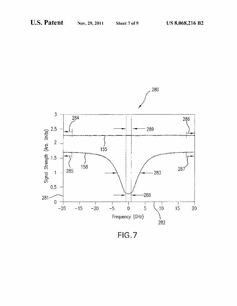
U.S. Patent Nov. 29, 2011 Sheet 7 of 9 US 8,068,216 B2
/ 280
I^
3 284
2.5
2
155
1.5
285
0.5
158a 1 —
0.5
281-
0 i
—20 —15 —20
III I
I I
^ I
289^Ii I
I I
I I
I I
^ I
III I
III I
I I
I I
I II
I I
I
I I
—_-' — 288II
—5 0 5
Frequency (GHz)
286
283
10 15 20
282
FIG.7

U.S. Patent Nov. 29, 2011 Sheet 8 of 9 US 8,068,216 B2
400401
SWEEP LASER ENERGY ACROSS A PREDETERMINED FREQUENCYSPECTRUM CENTERED ABOUT A PEAK ABSORPTION FREQUENCY
OF A VAPOR FILTER
402
DETECT LASER ENERGY AT A PLURALITY OF RECEPTION POINTSCORRESPONDING TO UNFILTERED SCATTERED LASER ENERGY,
FILTERED SCATTERED LASER ENERGY, FILTERED LASER ENERGY ANDUNFILTERED LASER ENERGY
403 404
DETERMINE NORMALIZED FILTER TRANSMISSION DETERMINE NORMALIZED ATMOSPHERIC RETURNBY DIVIDING BY A MAGNITUDE OF FILTERED BY DIVIDING A MAGNITUDE OF FILTERED
LASER ENERGY BY MAGNITUDE OF UNFILTERED SCATTERED LASER ENERGY BY A MAGNITUDELASER ENERGY ON A PULSE BY PULSE BASIS OF UNFILTERED SCATTERED LASER ENERGY ON A
PULSE BY PULSE BASIS
407406
408
DETERMINE OPTICALTRANSMISSION OF THE
VAPOR FILTER BYDIVIDING A MAGNITUDE
OF FILTERED LASERENERGY BY AMAGNITUDE OF
UNFILTERED LASERENERGY ON A PULSE BY
PULSE BASISCORRESPONDING TO
FREQUENCIES GREATERTHAN +/- 18GHz ABOUT
A PEAK ABSORPTIONFREQUENCY
DETERMINE SIGNALSTRENGTH RATIO BY
DIVIDING A MAGNITUDEOF FILTERED LASER
ENERGY BY AMAGNITUDE OF
UNFILTERED LASERENERGY ON A PULSE BY
PULSE BASISCORRESPONDING TO
FREQUENCIES BETWEEN+/- 0.5GHz
DETERMINE RAYLEIGHSCATTERING SIGNALSTRENGTH RATIO BY
DIVIDING A MAGNITUDEOF FILTERED SCATTERED
LASER ENERGY BY AMAGNITUDE OF
UNFILTERED SCATTEREDLASER ENERGY ON A
PULSE BY PULSE BASISCORRESPONDING TO
FREQUENCIES BETWEEN+/- 0.5GHz
DETERMINE MIESCATTERED SIGNAL
STRENGTH RATIO BYDIVIDING A MAGNITUDE
OF FILTERED SCATTEREDLASER ENERGY BY A
MAGNITUDE OFUNFILTERED SCATTEREDLASER ENERGY ON A
PULSE BY PULSE BASISCORRESPONDING TO
FREQUENCIES GREATERTHAN +/- 18GHz ABOUT
A PEAK ABSORPTIONFREQUENCY
409I DETERMINE RAYLEIGH LASER FILTER CONVOLUTION
410ACCESS RAYLEIGH LOOKUP TABLE CORRESPONDING
TO THEORETICAL RAYLEIGH LASER FILTER CONVOLUTIONTO DETERMINE AIR TEMPERATURE AND AIR PRESSURE
FIG. 8
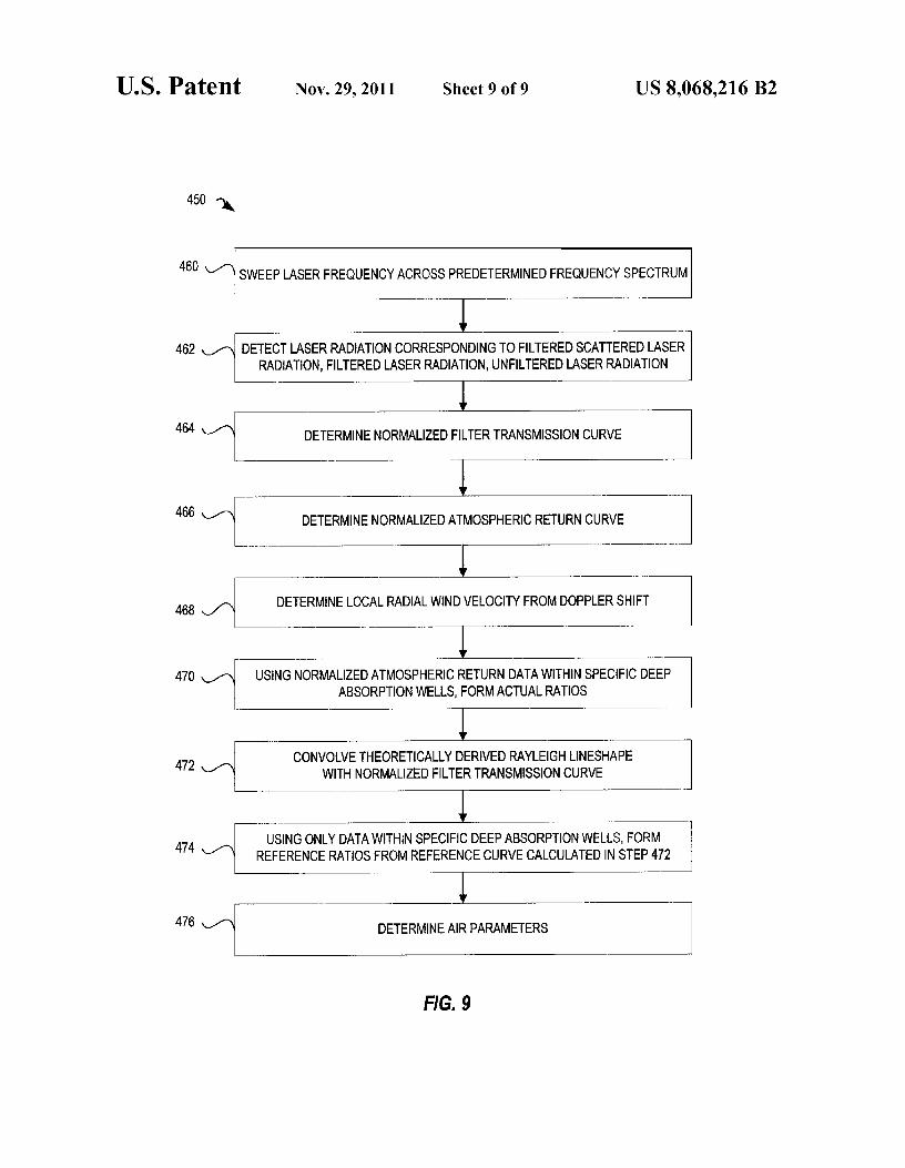
450 -)%,
SWEEP LASER FREQUENCY ACROSS PREDETERMINED FREQUENCY SPECTRUM
---- - ------
DETECT LASER RADIATION CORRESPONDING TO FILTERED SCATTERED LASERRADIATION, FILTERED LASER RADIATION, UNFILTERED LASER RADIATION
DETERMINE NORMALIZED FILTER TRANSMISSION CURVE
DETERMINE NORMALIZED ATMOSPHERIC RETURN CURVE
DETERMINE LOCAL RADIAL WIND VELOCITY FROM DOPPLER SHIFT
USING NORMALIZED ATMOSPHERIC RETURN DATA WITHIN SPECIFIC DEEPABSORPTION WELLS, FORM ACTUAL RATIOS
CONVOLVE THEORETICALLY DERIVED RAYLEIGH LINESHAPEWITH NORMALIZED FILTER TRANSMISSION CURVE
USING ONLY DATA WITHIN SPECIFIC DEEP ABSORPTION WELLS, FORMREFERENCE RATIOS FROM REFERENCE CURVE CALCULATED IN STEP 472
DETERMINE AIR PARAMETERS
460 _^
462 \,^
464 \-^
466 \_^
468
470 `/
472 \_^
474 `^
476 ,_^
U.S. Patent Nov. 29, 2011 Sheet 9 of 9 US 8,068,216 B2
FIG. 9
US 8,068,216 B21
OPTICAL AIR DATA SYSTEMS ANDMETHODS
CROSS-REFERENCE TO RELATEDAPPLICATIONS
This application is a divisional of U.S. patent applicationSer. No. 11/488,259 filed 17 Jul. 2006 now U.S. Pat. No.7,564,539, which claims benefit of priority to U.S. Provi-sional Patent Application Ser. No. 60/699,630 filed Jul. 15,2005. U.S. patent application Ser. No. 11/488,259 is also acontinuation-in-part of U.S. patent application Ser. No.11/103,020 filed 11 Apr. 2005, now U.S. Pat. No. 7,400,385,which is a continuation of U.S. patent application Ser. No.10/632,735 filed Aug. 1, 2003, now U.S. Pat. No. 6,894,768,which claims benefit of priority to U.S. Provisional PatentApplication Ser. No. 60/400,462 filedAug. 2, 2002. All of theaforementioned applications are hereby incorporated hereinby reference.
U.S. GOVERNMENT RIGHTS
This invention was made in part with the support of theU.S. Government; the U.S. Government has certain rights inthis invention as provided for by the tennis of Grant #NAS4-02043 awarded by the NASA Dryden Flight Research Center.
BACKGROUND
An Air Data System ("ADS") provides sensed telemetryinforming pilots, navigators or Vehicle Management Systemcomputers of air parameter(s) affecting aircraft stability.These air parameters include, for example, air speed, airtemperature and air pressure, each being useful for navigationand flight control. The ADS exists in many forms, forexample, as mechanical, opto-mechanical or opto-electronicdevices.
An Optical Air Data System ("OADS") uses light to deter-mine parameters of air speed. The OADS transmits lightpulses into the atmosphere and receives light that aerosolsreflect or "backscatter" towards the aircraft. Aerosols are finesolids and/or liquid particles suspended in air or other gases.The OADS may also measure the Doppler effect by receivingbackscattered light and measuring its return frequency todetermine speed. Certain prior art OADSs rely on scatteredlight that is unpredictable because of aerosol distributionsthat vary significantly with altitude and cloud content. Inaddition, some regions of the atmosphere contain too fewaerosols to enable reliable air data measurements, and such anOADS cannot determine air temperature or air pressure.
SUMMARY
In an embodiment, a method for remotely sensing air out-side a moving aircraft includes generating laser radiationwithin a swept frequency range. A portion of the laser radia-tion is projected from the aircraft into the air to induce scat-tered laser radiation. Filtered scattered laser radiation, filteredlaser radiation, and unfiltered laser radiation are detected. Atleast one actual ratio is determined from data correspondingto the filtered scattered laser radiation and the unfiltered laserradiation. One or more air parameters are determined bycorrelating the actual ratio to at least one reference ratio.
In an embodiment, a method for remotely sensing air out-side a moving aircraft includes generating laser radiationwithin a swept frequency range, wherein the swept frequencyrange includes at least two absorption features of at least one
2band stop filter. A portion of the laser radiation is projectedfrom the aircraft into the air to induce scattered radiationFiltered scattered laser radiation, filtered laser radiation, andunfiltered laser radiation are detected. A normalized atmo-
5 spheric return curve is determined from the filtered scatteredlaser radiation and the unfiltered laser radiation; a normalizedfilter transmission curve is determined from the filtered laserradiation and the unfiltered laser radiation. At least one actualratio is determined from the normalized atmospheric return
10 curve. At least one reference ratio is determined from thenormalized filter transmission curve and a Rayleigh lineshape corresponding to one or more estimated air parameters.One or more air parameters are determined by correlating theat least one actual ratio to the at least one reference ratio.
15 In an embodiment, a method for remotely sensing air out-side a moving aircraft includes generating laser radiationwithin a swept frequency range. A portion of the laser radia-tion is projected from the aircraft into the air to induce scat-tered radiation. Filtered scattered laser radiation, filtered laser
20 radiation, unfiltered scattered laser radiation, and unfilteredlaser radiation are detected. A normalized filter transmissionand a normalized atmospheric return are determined from thefiltered scattered laser radiation, filtered laser radiation, unfil-tered scattered laser radiation, and unfiltered laser radiation.
25 A plurality Doppler line shifts and a plurality of radial windvelocities are determined from a plurality of frequency shiftsbetween the normalized filter transmission and the normal-ized atmospheric return, wherein each frequency shift corre-sponds to an absorption feature of at least one band stop filter.
30 In an embodiment, a system for sensing of air outside amoving aircraft includes at least one laser for generating laserradiation and at least one transceiver for projecting the laserradiation to the air and for receiving scattered laser radiationfrom the air. Additionally, the system includes at least one
35 band stop filter selected from the group consisting of a fixedfrequency atomic vapor filter, an interference filter, a dichroicfilter, a fiber Bragg grating filter, a Rugate filter, and combi-nations thereof. Furthermore, the system includes a computerfor controlling the laser and for processing signals from the
40 transceiver to determine one or more air parameters based onthe scattered laser radiation.
In an embodiment, a software product includes instruc-tions, stored on computer-readable media, wherein theinstructions, when executed by a computer, perform steps for
45 remotely sensing air outside a moving aircraft. The softwareproduct includes instructions for generating laser radiationwithin a swept frequency range. The software product alsoincludes instructions for determining a normalized atmo-spheric return curve from filtered scattered laser radiation and
50 unfiltered laser radiation and instructions for determining anormalized filter transmission curve from filtered laser radia-tion and the unfiltered laser radiation. Furthermore, the soft-ware product includes instructions for determining at leastone actual ratio from the normalized atmospheric return
55 curve and instructions for determining at least one referenceratio from the normalized filter transmission curve and aRayleigh line shape corresponding to one or more estimatedair parameters. Also included within the software product areinstructions for determining one or more air parameters by
60 correlating the at least one actual ratio to the at least onereference ratio.
BRIEF DESCRIPTION OF THE DRAWINGS
65 FIG. 1 shows one Optical Air Data System ("OADS"),according to an embodiment.
FIG. 2 shows one OADS, according to an embodiment.
US 8,068,216 B23
FIG. 3 shows one graph useful in illustrating an exemplaryair speed calculation with an OADS, according to an embodi-ment.
FIGS. 4-7 show graphs illustrating exemplary calculationsfor other air parameters with an OADS, according to anembodiment.
FIG. 8 is a flowchart showing one exemplary method ofoperation of an OADS, according to an embodiment.
FIG. 9 is a flowchart showing one exemplary method ofoperation of an OADS, according to an embodiment.
DETAILED DESCRIPTION OF THE DRAWINGS
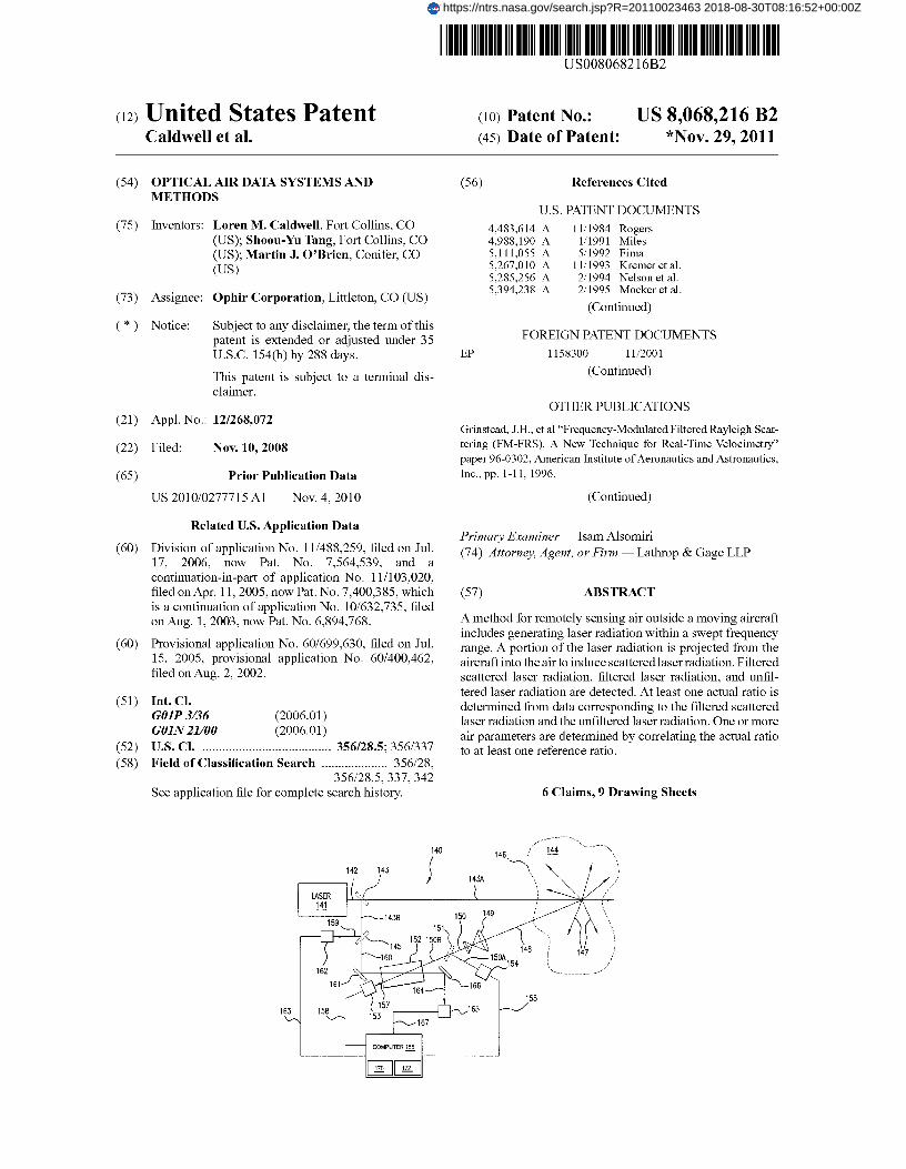
FIG.1 shows one Optical Air Data System ("OADS") 101mounted on or within an aircraft 102. In this embodiment,OADS 101 is configured for projecting laser radiation 103 toair 104. Laser radiation 103 impinges on air 104 and aerosolparticles 105 (in air 104), causing scattering of laserradiation103, which is represented in FIG. 1 as a scatter field 106.Distance between aircraft 102 and scatter field 106 is con-trolled by overlap between laser radiation 103 and the trans-ceiver 110 field of view at a distance from aircraft 102, toprovide an optimized intensity for return laser radiation 107and to eliminate possible measurement error arising fromdisplaced air proximate to aircraft 102. OADS 101 detectsbackscattered laser radiation 107 that is backscattered fromair 104 at laser scatter field 106. Radiation 107 may be in theultra-violet (UV) spectrum, for example, having a wave-length within a range of 250 mu to 270 mu; however, otherranges may alternatively be used to produce scatter field 106.
Return laser radiation 107 typically contains molecularscattered (e.g., Rayleigh) components 107A and/or aerosolscattered (e.g., Mie) components 107B. OADS 101 distin-guishes the molecular scattered components 107A from theaerosol scattered components 107B and correspondinglydetermines one or more air parameters based on backscat-tered laser radiation 107. Examples of such air parametersinclude air speed, air pressure, air temperature and/or aircraftorientation angles relative to the local wind. OADS 101 maybe configured with other aircraft as well, such as unmannedair vehicles (UAVs), helicopters, gliders and space shuttles.Although illustrated within a "nose" 108 of aircraft 102,OADS 101 may be configured in any other part of aircraft102.
As shown in FIG. 1, OADS 101 includes a laser 109 con-figured for generating laser radiation 103. Transceiver 110 isconfigured for transmitting laser radiation 103, from laser 109via optical coupling 111, and receiving backscattered laserradiation 107. Optical coupling 111 may exist in the form ofa fiber optic connection or free space transmission. Accord-ingly, transceiver 110 projects the laser radiation as laserradiation 103 to air 104. Air 104 scatters laser radiation 103 atscatter field 106 in a plurality of directions (e.g., illustrated asvectors 112). Scatter field 106 also returns, or backscatters,radiation 107 towards transceiver 110, which subsequentlyreceives the backscattered laser radiation 107. Transceiver110 converts backscattered laser radiation 107 to processableelectronic signals, via computer 113, to determine the airparameters.
Computer 113 communicatively couples with transceiver110 andprocesses signals from transceiver 110 to distinguisha molecular scattered component 107A from an aerosol scat-tered component 107B. Computer 113 determines the airparameters based on laser radiation 107 backscattered frommolecules and/or aerosols in air 104. Accordingly, as
4described below, computer 113 may employ one or moredigital signal processing algorithms to determine suchparam-eters.
While OADS 101 illustrates one transceiver 110 in an5 exemplary embodiment, a plurality of transceivers may be
used, depending on an application. For example, a helicopteremploying OADS 101 may use two transceivers 110 to deter-mine air parameters such as a forward velocity (e.g., airspeed) and a horizontal plane, or "yaw", of the helicopter. An
io airplane may use three transceivers 110 positioned in a par-ticular manner to determine various aircraft geometries, suchas angle of attack and sideslip, in addition to the air param-eters of air speed, air pressure and air temperature. In addi-tion, air vehicles (fixed wing and rotary) may employ three or
15 more transceivers and/or lasers to increase Optical Air DataSystem reliability through a redundant system architecture.Using three OADS transceivers mounted orthogonally to oneanother may fully resolve a total airspeed vector by providingthree independent measurements for the air speed vector (i.e.,
20 corresponding to three axes of a Cartesian coordinate sys-tem). The transceivers are for example located in uncommonplanes and their geometry respective of a known aircraftcenter-line. Vector algebra may then be used to determine thefull airspeed vector, including forward air speed, angle-of-
25 sideslip and angle-of-attack.FIG. 2 shows one OADS 140. OADS 140 illustrates
another embodiment used for determining air parameters,such as those described in FIG. 1, based upon laser radiationbackscattered from both air molecules and aerosols. In this
30 embodiment, OADS 140 includes laser 141 configured forgenerating laser radiation 142. Laser 141 may be a tunablelaser having a tuned center wavelength of about 253.7 mu,although other wavelengths may be used. For example, laser141 may be a frequency quadrupled, Nd:YAG (i.e., neody-
35 mium:yttrium-aluminum-garnet) pumped Ti:Sapphire (tita-nium-sapphire) laser. Alternatively, frequency-quadrupledYb-doped (ytterbium-doped) fiber lasers may be used thatoffer important benefits of smaller size, lighter weight,increased robustness and improved reliability, as compared to
4o Nd:YAG-pumped Ti: Sapphire lasers. Laser 141 may generatelaser radiation that is tunable across a frequency range ofabout 40 GHz; laser 141 may be a continuous wave laserwhich sweeps in frequency across this range, or it may be apulsed laser controlled such that each pulse has a frequency
45 distribution centered about a tunable peak frequency. In oneembodiment, the peak frequency increments by about 100MHz from each pulse to the next. Laser 141 may tune +/-20GHz about a center frequency of approximately 1182.5 THz,or c/253.7 mu, where c is the speed of light (approximately
50 3x10$ m/s). In the illustrated embodiment, laser 141 radiateslaser radiation 142 to beam splitter 143, which splits the beaminto two components, 143A and 143B. Component 143A isdirected through air 144; component 143B is directed to beamsplitter 145.
55 In particular, component 143A of laser radiation 142directed to air 144 is scattered into scatter field 146. Scatter-ing of component 143A is illustrated by scattering vectors147 in scatter field 146, whereas return scattering is illustratedby backscattered laser radiation 148. Component 143B of the
60 laser radiation 142 is used as a reference for comparison tobackscattered laser radiation 148. Such a comparison is forexample useful in determining air parameters such as airspeed, since transmitted and received frequencies of the laserradiation may be ascertained for use in a Doppler equation;
65 such a process is explained in greater detail herein below.In the illustrated embodiment, backscattered laser radia-
tion 148 is received through optics 149. In one example,
US 8,068,216 B25
optics 149 is a telescope that gathers backscattered laserradiation 148 into a beam 150. Optics 149 also directs beam150 to beam splitter 151, to split beam 150 into two compo-nents 150A/150B. Component 150B of beam 150 passesthrough vapor filter 152 to detector 153 to produce electronicsignal 158 representative of the component 150B impingingdetector 153; whereas component 150A is directed by beamsplitter 151 to detector 154.
In one embodiment, detector 154 is a photodetector thatreceives radiation 150A and converts it into an electronicsignal 155. Detector 154 connects to a central computer 156to process electronic signal 155. Similarly, detector 153 is aphotodetector configured for detecting component 150B,whichis filtered by vapor filter 152 as filtered component 157.Detector 153 converts component 157 to an electronic signal158 for processing by central computer 156.
Accordingly, electronic signal 158 corresponds to back-scattered laser radiation 148 as filtered by vapor filter 152;and electronic signal 155 corresponds to unfiltered backscat-tered laser radiation 150A. Electronic signal 155 is thus usedto nullify certain anomalies as computer 156 processes elec-tronic signal 158. For example, when processed with elec-tronic signal 158, signal 155 may be used to remove, fromsignal 158, certain laser transmission power fluctuations infiltered component 157 caused by atmospheric changes in air144. Such a process is explained in more detail in connectionwith FIGS. 4-7.
Computer 156 includes lookup tables 170 and 172 that maybe utilized to determine temperature and/or pressure as dis-cussed below.
Reference component 143B of the laser radiation 142 issplit into two components 159 and 160 by beam splitter 145.Component 160 is directed by beam splitter 145 to vapor filter152 via mirrored surface 161, to measure filter characteris-tics, whereas component 159 is directed by beam splitter 145to detector 162, to generate electronic signal 163. Electronicsignal 163 is for example used to normalize power fluctua-tions in the return of backscattered laser radiation 148 causedby power fluctuations in the generation of laser radiation 142by laser 141. Such a process is explained in more detail inFIGS. 4-7.
Vapor filter 152 filters component 160 to produce filteredcomponent 164. Filtered component 164 is directed to detec-tor 165, via mirrored surface 166, and then converted to anelectronic signal 167. Central computer 156 processes elec-tronic signal 167 to determine filter characteristics, such asfrequencies and suppression features of the band stop regionof vapor filter 152. One suchprocess is also explainedinmoredetail in context of FIGS. 4-7.
It should be noted that while FIG. 2 shows OADS 140 ashaving free space optical transmission and optical compo-nents such as beam splitters 143,145 and 151 and mirrors 161and 166, optical fiber may be used for laser 141 transmissionalong paths 142, 143A, 143B, 159, 160, 164, 150, 150A,150B and/or 157; in such an embodiment, fiber splitters maybe used in place of beam splitters 143, 151 and 145, andmirrors 161 and/or 166 may be eliminated.
It will also be appreciated that although the embodimentshown in OADS 140 of FIG. 2 employs vapor filter 152, othertypes of filters may be utilized. For example, notch or band-stop filters such as interference filters, dichroic filters, fiberBragg grating filters and/or Rugate filters may be utilized. Afilter used in place of vapor filter 152 may advantageouslyhave properties such as: (1) high optical absorption within astop-bandregion on the order of 40-60 dB or more; (2) a notchfilter absorption width between about 5 GHz and 40 GHz,with an absorption width under 10 GHz being preferred; and
6(3) steep absorption sidewalls, with a 10%-90% absorptiontransition occurring within about 5 GHz or less. Pass-bandfilters may also be used, such as when they operate in areflection mode such that a reflection produces a stop-band
5 filter. Single filters with multiple absorption features may beutilized, or optical or fiber splitters may be used to routeoptical signals through multiple filters, each filter having asingle absorption feature.
Filters other than atomic vapor filters may provide certain10 advantages. For example, while the absorption frequencies of
atomic vapor filters are reliably tied to properties of an atomicvapor used, their use may constrain an OADS to include atunable laser having output at such frequencies. However,
15 certain tunable lasers may have improved performance and/orstability at frequencies that do not conveniently match atomicvapor filter absorption frequencies. Certain filters such asinterference filters, dichroic filters, fiber Bragg grating filtersand/or Rugate filters may be designed to have absorption
20 features tuned to a preferred frequency output range of atunable laser, rather than tuning the laser to the filter. The useof a tunable laser selected on its merits, and a matching notchfilter in an OADS may thus (1) enable use of higher laseroutput power for improved return signal strength, (2) make
25 the OADS more robust with respect to thermal stability,vibration and shock, (3) eliminate hazardous materials (e.g.,mercury) from the OADS, and/or (4) reduce size, weightand/or cost of the OADS.
FIG. 3 shows one graph 200 useful in illustrating an exem-30 plary air speed calculation with OADS 140. Graph 200 shows
two curves, 201 and 202, comparing normalized laser radia-tion magnitudes as a function of frequency (signal strength,that is, normalized laser radiation magnitude, is plotted with
35 respect to axis 205, and frequency is plotted with respect toaxis 204). Curve 202 exemplifies filtered radiated laser radia-tion such as that of filtered component 164 of FIG. 2. As such,curve 202 shows filter characteristics of vapor filter 152 ofFIG. 2 determined by processing of electronic signal 167.
40 Curve 202 shows a peak absorption of filter 152 occurring ata down-translated frequency of 0 GHz. By way of example,the actual peak absorption frequency of filter 152 may beabout 1182.5 THz (i.e., having a corresponding wavelength ofabout 253.7 mu).
45 Laser radiation 142 generated by laser 141 passes throughfilter 152 to provide filtered component 164. Once filteredcomponent 164 is converted to electronic signal 167 by detec-tor 165, computer 156 analyzes and stores features of vaporfilter 152 through digital signal processing of signal 167 (e.g.,
50 computer 156 stores reference features, obtained under con-trolled conditions, for use in future calculations). As shown inthis example, features of vapor filter 152 have approximately10% normalized absorption at approximately +1-5 GHz (i.e.,0.9 normalized transmission factor at approximately +1-5
55 GHz according to axis 205) about the peak absorption fre-quency. Other types of suitable filters may include differentabsorption/transmission features.
Curve 201 exemplifies filtered backscattered laser radia-tion such as that of filtered component 157 of FIG. 2. In one
60 embodiment, curve 201 is used to determine air speed bycomparison to curve 202. For example, curve 202 illustrateshow vapor filter 152 affects laser radiation 142; curve 201similarly illustrates how vapor filter 152 affects laser radia-tion 142 as laser radiation 142 is backscattered (e.g., returns
65 as radiation 148) from air 144. Frequency shift 203 representsthe change in frequency of peak absorption for vapor filter152 between transmitted laser radiation 142 and returned

US 8,068,216 B27
laser radiation 148. Computer 156 processes algorithmsapplying Doppler velocity equation to determine air speedfrom frequency shift 203.
To determine air speed in one embodiment, computer 156determines how far in frequency the peak absorption fre-quency of filtered component 157 has shifted from the initiallaser frequency by comparing curve 202 to curve 201 (e.g.,comparing peak absorption frequencies of filtered compo-nents 157 and 164). Frequency shift 203 substantially equatesto a radial wind velocity through the Doppler velocity equa-tion:
8her of scatterers (i.e., molecules for Rayleigh, aerosols forMie) per unit volume of atmosphere.
Next, computer 156 may determine other air parameters,utilizing the result obtained for the measured intensity of the
5 returned laser energy. Such a process, for example, may beginby determining characteristics of vapor filter 152 by transmit-ting of reference laser radiation 160 through vapor filter 152.For example, measuring band stop characteristics of vaporfilter 152 with laser 141 (e.g., via component 143B to elec-
io tropic signal 167) during experimentation yields a convolu-tion of the laser wavelength and the filter according to thefollowing equation:
2VR (Eq. 1)O V = ;L
where AvD represents the Doppler frequency shift, VR repre-sents velocity component of the vehicle (e.g., aircraft 101 ofFIG. 1) along the laser direction of propagation 143A and Xrepresents the wavelength of laser radiation 142.
In one embodiment, wind velocity component VR may bemeasured by determining the frequency shift from curve 202of graph 200 as compared to curve 201 of graph 200. This isaccomplished by calculating a symmetry point of each curve201 and 202 and determining a difference in symmetry pointsbetween the two curves.
Vapor filter 152 may have a plurality of absorption features.Consequently, OADS may have a plurality of absorptionmaxima, such as those illustrated by curves 201 and 202 ofFIG. 3, which may be used to provide a more accurate esti-mate ofthevehicle's velocity. Thevehicle's velocity, VR , maybe calculated using equation 1 for each absorption feature. Anaverage velocity of the vehicle may then be calculated fromeach value of VR.
FIGS. 4-7 show graphs illustrating exemplary calculationsfor other air parameters with OADS 140. For example, afterdetermining frequency shift due to air speed as shown in FIG.3, other air parameters such as air temperature and air pres-sure may be calculated. In one example, computer 156 ini-tially determines an intensity measurement of the detectedbackscattered laser radiation (e.g., filtered component 157detected by detector 153) from electronic signal 158. Thisexperimentally verified intensity measurement of returnedlaser radiation corresponds to the following equation:
S,(v)PLTLDsT.,Esfdv fdvr ,_[L (v,, )E(v, v)(rR)(v, (v,,, OvD))+-M(v, (v,,, OvD)))] (Eq. 2)
where SS(v) is electronic signal 158 from detector 153; PL isthe laser power, TL is the transmission coefficient through air144 along laser path 143A, L(v,, ,9e„) is the laser line shapeinherent to the laser 141 output as a function of laser fre-quency v...... TR is the transmission coefficient through air144 along laser path 148, E, isoptical efficiency of the detec-tor channel though detector 153, F(v) is the band stop fre-quency range of vapor filter 152 centered at a frequency of v,R is Rayleigh scattering as a function of frequency (appli-cable to the Rayleigh regime) v,, for backscattered laser radia-tion minus the quantity of laser frequency v,,,,, minus theDoppler shift AVD, r is the Rayleigh scattering magnitudecoefficient dependent on air density and the Rayleigh back-scattering coefficient, M is Mie scattering as a function of v,,minus the quantity of v,,,,, minus AVD, m is the Mie scatter-ing magnitude coefficient dependent on aerosol concentra-tion and the Mie backscattering coefficient, and Ds isdetector153 efficiency. The Rayleigh backscattering coefficient r andthe Mie backscattering coefficient m are constant for a par-ticular atmosphere. These coefficients correspond to the num-
SF(v)=PLEFDFfdv,,,_[L(v,,,,)F'(v,,,, v)], (Eq. 3)
15 where S f,(v) is signal 167 from detector 165 as a function offrequency v (e.g., as illustrated in curve 221 of FIG. 4); E, isthe optical efficiency of filter 152 collection along paths 160and 164, and D, is detector 165 efficiency.
Note that all optical efficiencies F, and Es, capture signal20 losses that are optical in nature. For example, Ef the optical
efficiency for detector 165, includes the optical beam splittingratios for beam splitters 143 and 145, the optical transmissionand coupling across filter 152 and the optical delivery effi-ciency onto detector 165. ES the optical collection efficiency
25 for detector 153, includes the collection efficiency of tele-scope 149, the optical coupling efficiency into path 150, thebeam splitter ratio of beam splitter 151, the transmissionefficiency across filter 152 and the delivery efficiency ontodetector 153. Detector efficiencies D f,. and Ds include the
3o detector conversion efficiencies for detectors 165 and 153,respectively. Thus, D, is the conversion efficiency wherebydetector 165 converts laser radiation along path 164 into anelectrical signal 167. Likewise, Ds is the conversion effi-ciency whereby detector 153 converts laser radiation along
35 path 157 into an electrical signal 158.Backscattered laser radiation 148 may include power fluc-
tuations that are caused by laser 141 while generating laserradiation 142. Accordingly, laser radiation detected by detec-tor 162 (e.g., via component 159) may be utilized to normal-
40 ize power fluctuations attributable to laser 141. In oneembodiment, detector 162 converts component 159 into elec-tronic signal 163. In turn, computer 156 processes and nor-malizes according to the following equation:
45 SL(v) PLELD fdvL(v), (Eq. 4)
where SL(V) is the electronic signal 163 from detector 162, ELis the optical collection efficiency for detector 162, DL is theconversion efficiency of detector 162 and PL is the power oflaser 141. Note that the optical collection efficiency EL
50 includes the beam splitting ratios of beam splitters 143 and145 and the delivery efficiency of laser beam path 159 ontodetector 162.
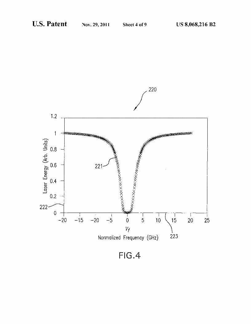
Curve 221 of graph 220 of FIG. 4 represents the magnitudeof laser radiation (component 164) filtered by vapor filter 152
55 and normalized between 0 and 1. Curve 221 represents themagnitude of the laser radiation as a function of frequency(i.e., laser radiation magnitude plotted with respect to axis222 and frequency plotted with respect to on axis 223). Curve221, therefore, illustrates filtered laser radiation via compo-
6o nent 160 as determined by computer processing of electronicsignal 167, plotted as laser radiation magnitude normalizedbetween 0 and 1, versus frequency.
In one embodiment, absorption/transmission characteris-tics of vapor filter 152 are normalized using Eq. 3 and Eq. 4.
65 Eq. 3 yields stop band characteristics of filter 152 and Eq. 4accounts for power fluctuations in the generation of laserradiation 142. With the power fluctuations of Eq. 4 substan-
US 8,068,216 B29
tially removed, a "normalization channel' is created, andpower fluctuations attributable to atmospheric changes maybe accounted for.
In one embodiment, additional power fluctuations causedby atmospheric changes in air 144 are also removed. Forexample, laser radiation detected by detector 154 (e.g., viacomponent 150A) assists in removing laser power fluctua-tions caused by atmospheric changes in air 144. Accordingly,detector 154 converts received laser radiation into electronicsignal 155. Computer 156, in turn, processes electronic signal155 to determine the normalized laser radiation magnitudeaccording to the following equation:
SN-PLTLTRENDrfdvfdvl,,_[L(v,,,_)(rR(v-(v,,_ov,,))+mM(v- (v,_ OvD)))] (E4 5)
where Sr, is the signal 155 from detector 154; Er, is opticalcollection efficiency of the detector 154 and Dr, is the con-version efficiency of detector 154.
In one embodiment, it is advantageous to normalize thevarious characteristic functions to enable a closed-loop solu-tion to the process of determining temperature and pressure.In one example, therefore, computer 156 calculates the nor-malized laser line shape according to following equation:
10
SF(v)PLEFDF J d vj ...fib vi ...)F'(vj_, - v)7
(Eq. 10)
SL( v) PLELDL f d vL(v)
5
Equation 10 simplifies to:
SF (v) EFDF O
(Eq. 11)10 - EE v
SL( v) ELDL
where LF(v) represents a convolution of functions L and F(that is, a function that represents the effects of functions L
15 and F combined at each frequency v).In one embodiment, tuning the laser 141 to a reference
frequency v, ,f far enough removed from the effects of thevapor filter 152 enables the measurement of the ratio of theoptical and detector efficiencies of the signal channels 167
20 (S,„ represented by Eq. 3 above) and 163 (Si, represented byEq. 4 above). This, in turn, enables the normalization of thesignal 167 measurement to one, for simultaneously checkingfor laser, detector and filter abnormalities on a scan-by-scanbasis:
fL (vj__)dvj_ 1 , (Eq. 6)25
where (as before) v..S... is laser line shape frequency and Ldenotes the laser line shape as a function of frequency. Inanother example, computer 156 calculates normalized Ray-leigh Function according to the following equation:
SF(v. f) EFDF (Eq. 12)
SL (v,f) - ELDL
fR (v.)dv, 1, (Eq. 7)
where R denotes the Rayleigh line shape as a function offrequency v,,, applicable to the Rayleigh regime. In anotherexample, computer 156 scales the electronic signal 167recorded from detector 165 by dividing all recorded values bythe maximum value according to the following equation:
MAX(SF(v))-1 , (Eq. 8)
where MAX denotes an operation that finds a maximum valueof a particular function, and S, denotes electronic signal 167measured from detector 165, as a function of frequency v (e.g.as illustrated in curve 221 of FIG. 4). In another example,computer 156 normalizes the Mie Function according to thefollowing equation:
SS(v)
SN (v)
MM-kv), (Eq. 9)
30 In one embodiment, LF(v) are determined to generate alook up table of the convolution of theoretical Rayleigh func-tions (calculated in terms of temperature and pressure) withthe measured filter function. Since the measured filter func-tion is already the convolution of the laser and filter spectra,
35 convolving the Rayleigh function with the measured filtersignal 167 yields the expected return signal from an atmo-sphere of pure Rayleigh scatterers.
In one embodiment, the measured signal 158, which is thebackscatter return from the atmosphere 144 that passes
40 through the vapor filter 152 (and is represented by Eq. 2above), is divided by the signal 155, which is the backscatterreturn from the atmosphere 144 that does not pass throughvapor filter 152 (and is represented by Eq. 5 above). Thiscalculation removes changes in signal transmission that areindependent of the factors to be measured:
(L(v t ...)F(v, - v)) (Eq. 13)
PL TL DsTREs^d v f d v ia,... rR(v, - (v j_ 1 - AVD )) +
mM ( v.-(V I, - A, ))
b V 1 ...)
PL TL TR EN DN fd v f d v ia,... rR(v, - (vaa,,, - Ova)) +
mM (v. - (Vl,,,, -Ova))
55 Since M is a delta function, Equation 13 simplifies to:
rLFR(va,„e, -Ova) + (Eq. 14)
SS(v) f ESDS l mLF(vj_,-Ova)60
SN(v) - LTN DNr+m
where 6(v) is the delta function.
In one embodiment, dividing the signal 167 collected fromdetector 165 (and represented by Eq. 3, above) by the signal 65163 collected from detector 162 (and represented by Eq. 4,above) removes laser 141 power fluctuations, as follows:
where LFR(v) represents a convolution of functions L, F andR in the sense of the convolution LF(v) discussed above.
In one embodiment, tuning laser 141 to reference fre-quency v,. ffar enough removed from the effects of the vaporfilter 152 enables the measurement of the ratio of the optical
US 8,068,216 B211
and detector efficiencies of the signal channels 158 (S S asrepresented by Eq. 2 above) and 155 (S r,as represented by Eq.5 above). This enables a check for abnormalities in the filteron a scan-by-scan basis:
SS(v.f) Es Ds (Eq. 15)
SN(V"f) EN DN
In one embodiment, a variable K,. fmay be defined as:
Ss(v. f) (Eq. 16)Krf=S
V"N( f)
12
Ss(vo) (Eq. 19)Ko
SN N)
5and then solving for the ratio
m = Koo LFR(vo) 1(Eq. 20)
( o) —10
Using the normalized signal return in the region of interest(i.e., the sloped region between the minimum and maximumof the signal return) and writing the result in terms of the ratio
15 of m over r, yields the following:
Once both data sets (i.e., Ss and Sr,) are symmetric aboutthe same data point, computer 156 calculates temperature andpressure from the return signal. Initially, computer 156 usestheoretical Rayleigh functions that are functions of tempera-ture and pressure in conjunction with the measured filtertransmission to generate a lookup table 170 that stores laser,Rayleigh, and filter (LFR(v)) convolutions that are dependenton atmospheric temperature and pressure. Computer 156 maythen compare a normalized return signal to a value stored inlookup table 170 to determine atmospheric temperature andpressure. In order to compare the return signal with thelookup table 170, computer 156 accounts for the magnitudeof Mie scatterers as well as any changes in air density that maychange the magnitude of the Rayleigh signal.
A vapor filter may be used as a bandstop filter; such filterstypically provide frequency stability, optical depth, and opti-mal filter shape. For the purposes of separating the Rayleighand Mie scattering, an optical depth of approximately 60 dBprovides excellent absorption of Mie scattering within a smallfrequency variance around v o (i.e., where vfis a normalizedfrequency of 0 GHz). For example, an atomic vapor filter mayprovide 60 dB of absorption in a frequency region that is notcontaminated by Mie scattering. This region may be used inacquiring initial estimates of pressure and temperature (ex-plained below in FIG. 5). Such absorption is observable inFIG. 5 below as the measured signal S, which has the mag-nitude of zero centered about v, This data provides informa-tion about pure Rayleigh scattering that may be used to cal-culate the ratio of Mie scattering to Rayleigh scattering, asshown in Eq. 17:
Ss(vo) — Es Ds ] rLFR(vo) + mLF(vo) (Eq. 17)
SN N) EN DN r+m
Since the vapor filter fully attenuates the Mie scattering in thi sregion:
Ss(vo) Es Ds 1IrLFR(vo) (Eq. 18)
SN(vo) — LEN DN r+m
where LFR(v o) is the value of the theoretical return signal atparticular atmospheric temperature and pressure. Accord-ingly, computer 156 calculates the ratio of Mie scattering byfirst defining a variable Ko as follows:
Ss (V)LFR(v) + mLF(v) (Eq. 21)
= Ka20 SN (v) 1 + m
r
Substituting the ratio of m and r of Eq. 20 into Eq. 21 yields:
25
Ss ( V) LFR(v)Ko (Eq. 22)
SN (v) — Ka
LFR(vo) +LF(v)II — KaLFR(vo)1
30 Solving for LFR(v) yields:
Ss(v) LFR(vo) 1 LFR(vo) (Eq. 23)LFR(v) =
SN (v) Ka +LF(v)^K̂ — Ko
35
where the measured signal return LFR(v) is written in termsof measured quantities and the theoretical values of LFR(vo).Computer 156 then calculates LFR(v) and compares it to thelookup table 170 to determine atmospheric temperature and
40 pressure, described in greater detail in FIG. 5.Accounting for power fluctuations, optical efficiencies and
detector efficiencies as described herein allows for an inde-pendent check on vapor filter 152 while OADS 140 operates.With variable characteristics of detector channels and power
45 fluctuations accounted for, computer 156 may determine, forexample, the substantially constant characteristics of vaporfilter 152, such that more accurate measurements of receivedbackscattered laser radiation (e.g., laser radiation 148) areobtained.
50 In one embodiment, the normalization channel depicted inFIG. 4 is used to remove atmospheric power fluctuations oflaser radiation 148. In doing so, computer 156 measuresRayleigh and Mie components of laser radiation 147 in termsof optical efficiencies and detector efficiencies. Such efficien-
55 cies are typically measured on a shot-by-shot basis during theanalysis process. In an exemplary embodiment of operation,laser 141 generates and transmits laser radiation 142 as aseries of pulses at a particular pulse repetition frequency("PRF"), while in other embodiments laser 141 is a continu-
60 ous wave laser (as discussed in connection with FIG. 2).Computer 156 then measures the Rayleigh and Mie compo-nents in terms of optical efficiencies and detector efficiencieson a pulse-by-pulse basis.
To measure Rayleigh components and Mie components, in65 one embodiment, OADS 140 tunes the frequency of the laser
radiation 142 transmittedby laser 141. For example, laser 141transmits the laserradiation 142 at distal frequencies from the

US 8,068,216 B213
14peak absorption frequency of filter 152 (illustrated by vfin
increasing temperature increases the Rayleigh lineshape
FIG. 4) to provide a frequency-independent measurement. width while increasing pressure increases the Rayleigh line-Computer 156 then determines the line shape of laser radia- shape height. Accordingly, for each incremental value of tem-tion 142 through filter 152. perature and/or pressure, the Rayleigh lineshape is unique.
In one embodiment, measured intensity of the detected 5 Such scattering theory is discussed in "On The Kinetic Modelbackscattered laser radiation (e.g., as determined by elec- Description Of Rayleigh-Brillouin Scattering From Molecu-tronic signal 158) is functionally compared to normalized
lar Gases", G. C. Tenti, D. Boley and R. C. Desai, Canadian
atmospheric factors. The measured intensity often depends
Journal of Physics, vol. 52, pg. 285-290 (1974).upon Mie scatterers (e.g., aerosols) and air density changes
In one example, computer 156 determines air density
due to altitude changes and temperature changes. The air io changes by aligning peak absorption frequencies of curvesdensity changes and the temperature changes are not, how- 241, 242 and 243, illustrated at frequency of Since curve 243ever, removed through the normalization processes described
represents detected backscattered laser radiation containing
herein. For computer 156 to accurately determine air param- substantially no Mie scattering, curve 243 may be used as aeters such as temperature and pressure of air 144, air density reference where Mie scattering has been eliminated. In onechanges are removed from the detected backscattered laser 15 example, computer 156, therefore, uses curve 243 to removeradiation so that computer 156 may accurately determine the the effects of Mie scattering by aligning curves 241, 242 andair parameters. 243 and by calculating a ratio of the detected backscattered
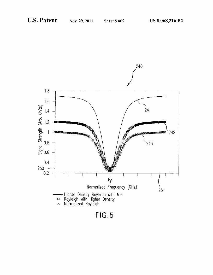
FIG. 5 shows graph 240 with curves 241 (detected back- laser radiation to theoretically pure Rayleigh scattering (thescattered laser radiation at a higher air density causing both
ratio of curves 241 and 242) which may be utilized to deter-
Rayleigh and Mie scattering), 242 (detected backscattered 20 mine air density. Mie scattering effects are then removed bylaser radiation at an air density causing Rayleigh scattering)
subtracting curve 243 from the calculated ratio of curves 241
and 243 (normalized Rayleigh scattering). Curves 241, 242
and 242. With Mie scattering essentially removed from theand 243 illustrate laser radiation magnitudes (plotted with
measurement, computer 156 more accurately determines air
respect to axis 250) as a function of frequency (plotted with
temperatures and air pressures.respect to axis 251). In one embodiment, computer 156 pro- 25 FIGS. 6 and 7 show other exemplary graphs that may becesses data from curves 241, 242 and 243 to determine other used in determining air pressure and air temperature. FIG. 6air parameters. For example, Mie scattering effects are sub- illustrates a graph 260 of electronic signals 163 and 167 ofstantially isolated and removed from calculations to deter- FIG. 2 respectively generated by detectors 162 and 165 ofmine air temperature and air pressure, since these Mie scat- FIG. 2. Graph 260 shows electronic signals 163 and 167, thattering effects produce inaccurate measurements due to so represent light intensity as a function of normalized signalinconsistent aerosol concentrations. strength (axis 261), versus frequency (axis 262). FIG. 7 illus-
In one embodiment, to determine the air temperature and
trates a graph 280 of electronic signals 158 and 155 (see FIG.air pressure, computer 156 processes the data from curves
2) generatedby detectors 153 and 154 respectively, represent-
241, 242 and 243 to substantially isolate and remove the Mie
ing light intensity as a function of normalized signal strengthscattering effects, such as those found in curve 241. In pro- 35 (axis 281), versus frequency (axis 282). These four lightcessing the data from curves 241, 242 and 243, computer 156
intensities (represented by electronic signals 163, 167, 158
calculates lookup table 170 in substantially real time using a and 155) may be measured, over time, through transmissionmeasured laser/filter profile (i.e., as measured at detector 165
and collection of light corresponding to laser pulses, or they
of FIG. 2) convolved with theoretical Rayleigh functions for maybe measured through transmission and collection of lighta particular temperature and pressure (e.g., illustrated by 40 corresponding to a continuous wave laser whose frequencycurves 242 and 243). Computer 156 then scales the measured
varies continuously. In one example, a transmission fre-
return signal LFR(v) (i.e., illustrated by curve 241 in this quency of laser radiation 142 of FIG. 2 generated by laser 141example) with the ratio of m to r determined by Eq. 20. at a certain PRE may sweep such that each laser pulse isComputer 156 then analyzes data near the deepest portion of
emitted at a different frequency. Electronic signals 163 and
the filter attenuation (i.e., approximately +1-0.5 GHz from vf) 45 167 therefore illustrate how laser radiation 142 of laser 141to estimate pressure and/or temperature. This portion corre- may sweep in frequency across an absorption band 263 of thesponds to a 60 dB region of absorption that is not contami- vapor filter 152. Illustratively, FIG. 6 shows one completenated by Mie scattering. Use of this region is a preferred
frequency sweep of laser radiation 142 generated by laser 141
aspect of the calculation technique that provides temperature and detected by detectors 162 and 165. Similarly, electronicand pressure accuracy by providing a reliable temperature 50 signals 155 and 158 of FIG. 7 show detected signals of detec-base from which to increment temperature and/or pressure tors 153 and 154 as laser radiation 142 of laser 141 performsestimates. a complete sweep in frequency across absorption band 283 of
Computer 156 calculates theoretical Rayleigh return vapor filter 152.assuming an initial temperature estimate and performs a
From signals 163 and 167, computer 156 may for example
Least Square Error (LSE) calculation to determine the accu- 55 determine a normalized filter transmission, by dividing dis-racy of the temperature with respect to the theoretical Ray- crete points of electronic signal 167 by corresponding dis-leigh function. Computer 156 repeats the process with incre- crete points of signal 163. Similarly, computer 156 may deter-mental changes to temperature and/or pressure until an mine a normalized atmospheric return though vapor filter 152optimal fit (i.e., an LSE calculation that corresponds to design
by dividing discrete points of signal 158 by corresponding
specifications) is achieved. Although discussed in detail with 6o discrete points of signal 155. These discrete points, describedrespect to LSE, other approximation methods, such as New- herein, correspond to individual pulses of laser radiation 142.ton-Raphson and Monte Carlo, may be used in alternative
Using normalized calculations of filter transmission (e.g.,
embodiments. Accordingly this disclosure teaches by way of
from graph 260) and the normalized calculations of atmo-example and not by limitation. spheric return (e.g., from graph 280), computer 156 deter-
Temperature affects air density in a manner that is recip- 65 mines relative optical efficiencies in the vapor filter 152.rocal to pressure; increasing pressure increases density, while
In one embodiment, computer 156 determines optical
increasing temperature decreases density. Additionally, transmission for vapor filter 152 using the frequency inde-
US 8,068,216 B215
16pendent components of data from graph 260, FIG. 6 (there is tered through the filter (e.g., component 157 of FIG. 2). Forsubstantially no change in amplitude for signals 163 and 167
simplicity, these components are hereinafter referred to as: 1)
at frequencies greater in magnitude than ±18 GHz from 0
unfiltered laser radiation; 2) filtered laser radiation; 3) unfil-GHz illustrated at points 264, 265, 266 and 267). Computer tered backscattered laser radiation or unfiltered scattered156 therefore determines a ratio of optical transmission for 5 laser radiation; and 4) filtered backscattered laser radiation orvapor filter 152 by calculating a ratio of signal 167 to signal
filtered scattered laser radiation.
163, via frequency corresponding points of the signals, for
After detecting the four components of laser radiation, apoints representing frequencies greater in magnitude than computer (e.g., computer 156, FIG. 2), determines normal-±18 GHz from 0 GHz. ized filter transmission of the vapor filter, in step 403. For
Similarly, computer 156 determines a magnitude of inten- io example, the computer, in one embodiment, processes thesity of atmospheric-returned laser radiation received through
unfiltered laser radiation and filtered laser radiation by divid-
vapor filter 152 using the frequency independent parts of the
ing the magnitude of the filtered laser radiation by the mag-data from graph 280, FIG. 7 (there is substantially no change nitude of the unfiltered laser radiation. In one embodiment,in amplitude for signals 155 and 158 at frequencies greater in the division is performed on a pulse by pulse basis, wheremagnitude than ±18 GHz from 0 GHz illustrated at points 15 divided magnitudes of the pulses have corresponding fre-284, 285, 286 and 287). Computer 156 thereby determines a quencies.ratio of atmospheric return with the laser power measurement
The computer also determines, in one embodiment, a nor-
by calculating a ratio of signal 158 to signal 155 via frequency malized atmospheric return of the laser radiation, in step 404.corresponding points of the signals for points representing the
For example, the computer may process the filtered backscat-
frequencies greater in magnitude than ±18 GHz from 0 GHz. 20 tered laser radiation and unfiltered backscattered laser radia-In one embodiment, computer 156 calculates a ratio of
tion by dividing the magnitude of the filtered backscattered
signal 158 to signal 155 for frequencies between ±0.5 GHz
laser radiation by the magnitude of the unfiltered backscat-(illustrated at points 288 and 289). Such a frequency range tered laser radiation. Again, in one embodiment, division isincludes substantially no Mie scattering of laser radiation 142
performed on a pulse by pulse basis, where divided magni-
for air 144; it thus corresponds to substantially pure Rayleigh 25 tudes of the pulses have corresponding frequencies.scattering. Computer 156 thus compares a Rayleigh to Mie
Once normalized filter transmission and normalized atmo-
scattering strength based upon the ratio of signal 158 to signal
spheric return of the laser radiation are determined, the com-155. Computer 156 determines Rayleigh to Mie scattering puter determines signal strengths for each of the filter trans-strength by comparing a ratio of signal 158 to signal 155 at mission and the atmospheric return. For example, thefrequencies between ±0.5 GHz to the ratio of signal 158 to 30 computer determines the optical transmission through thesignal 155 at frequencies greater than ±18 GHz from 0 GHz. filter by calculating a ratio of the filtered laser radiation to theIn one embodiment, computer 156 performs similar calcula- unfiltered laser radiation at particular frequency ranges, intions for "non-scattered" laser radiation 142 (e.g., component steps 405 and 407. The computer similarly determines the143B of FIG. 2) based on data illustrated in FIG. 6 using atmospheric return (scattering) signal strength through thepoints 268 and 269. Such a process is further described in 35 filter by calculating a ratio of the filtered backscattered laserFIG. 8. radiation to the unfiltered laser radiation at particular fre-
Ratios determined for the non-scattered laser radiation 142
quency ranges, in steps 406 and 408.and for the scattered laser radiation 142 may be used in
The computer also determines a signal strength ratio for the
tandem to numerically calculate Laser-Rayleigh-Filter con- normalized filter transmission by dividing filtered laser radia-volution (e.g., LRF(v)) from data. The Laser-Rayleigh-Filter 40 tion by unfiltered laser radiation, again on a pulse by pulseconvolution is in turn compared to a look up table of theoreti- basis, at frequencies greater in magnitude than about +/-18cal Laser-Rayleigh-Filter convolution values to determine
GHz about the peak absorption frequency, in step 407. The
temperature and pressure. computer further determines a signal strength ratio for theFIG. 8 shows a flowchart of one exemplary methodical
normalized filter transmission by dividing filtered laser radia-
operation 400 of an OADS. Method 400 may be partially or 45 tion by unfiltered laser radiation on a pulse by pulse basis atfully performed by computer 156 of OADS 140; computer
frequencies between about +1-0.5 GHz, in step 405. These
156 may receive operating instructions from software and/or signal strength determinations correspond to frequencyfirmware. A laser (e.g., laser 141 of FIG. 2) sweeps laser ranges where Mie scattering (e.g., +/-18 GHz) and Rayleighradiation across a predetermined frequency spectrum, in step scattering (e.g., +1-0.5 GHz) are most prevalent, and are thus401. The laser may sweep the laser radiation across a fre- 50 useful when combined with similar signal strength determi-quency range of about +/-20 GHz by transmitting laser radia- nations for the normalized atmospheric return. The computertion at a certain PRF (or it may sweep frequency continuously, determines a Mie scattering signal strength ratio for the nor-as discussed in connection with FIG. 2 above). In one malized atmospheric return of the laser radiation by dividingembodiment, the PRF is about 1 kHz, with a pulse width
filtered backscattered laser radiation by unfiltered backscat-
between about 50 ns and 100 ns, and a swept frequency range 55 tered laser radiation, again on a pulse by pulse basis, at fre-is centered about a frequency corresponding to apeak absorp- quencies greater in magnitude than about +/-18 GHz abouttion frequency (e.g., 260 mu) of a filter (e.g., vapor filter 152, the peak absorption frequency, in step 408. The computer alsoFIG. 2). determines a Rayleigh scattering signal strength ratio for the
Laser radiation is typically split into four distinct paths normalized atmospheric return of the laserradiation by divid-such that the laser radiation may be detected as four different 60 ing filtered scattered laser radiation by unfiltered backscat-inputs, in step 402. These four paths of laser radiation corre- tered laser radiation on a pulse by pulse basis at frequenciesspond to: 1) laser radiation transmitted by the laser (e.g., between about +1-0.5 GHz in step 406.component 159 of FIG. 2); 2) laser radiation transmitted by
With signal optical transmission for the filter and signal
the laser through the filter (e.g., component 164 of FIG. 2); 3)
strengths for both Rayleigh scattering and Mie scatteringlaser radiation transmitted by the laser into the air and back- 65 determined, the computer determines a Rayleigh laser filterscattered (e.g., component 150A of FIG. 2); and 4) laser convolution in step 409. For example, the computer, in oneradiation transmitted by the laser into the air and backscat- embodiment, performs a convolution of the optical transmis-

US 8,068,216 B217
sion with the Rayleigh and Mie scattering signal strengthscorresponding to the frequency ranges for Rayleigh and Miescattering of +1-0.5 GHz and +/-18 GHz, respectively. Thecomputer then accesses a lookup table, such as lookup table170 of FIG. 2, that has theoretical Rayleigh laser filter con-volution values to determine temperature and pressure of theair, in step 410.
It is also possible to calculate a convolution of a measuredfilter function with a theoretical Rayleigh-Brillouin return(Rayleigh line shape), and directly compare the convolutionwith filtered scattered laser radiation. This allows calculationof atmospheric parameters without calculating a deconvolu-tion of the Rayleigh-Brillouin signal, reducing the complex-ity of real-time calculations required to determine the atmo-spheric parameters. In particular, ratios of measured signalsmay be compared directly to theoretical ratios of a Rayleighline shape convolved with measured filter functions to allowself calibrating measurements. For example, signal strengthvariations across data gathering channels and power of scat-tered laser radiation may be inherently normalized when suchratios are used. Certain ratios of measured data at laser fre-quencies that lie within filtered bands of band-stop filters(e.g., absorption features of an atomic vapor cell, or equiva-lent features of other filters, as discussed above) may beuseful for determining temperature and pressure, since Miescattering is eliminated from the measured data. Calculationof convolutions may represent a lower computational burdenon a computer (e.g., computer 156 of OADS 140) as com-pared to calculating deconvolutions of measured data into andout of a Rayleigh-Brillouin representation.
For example, filtered scattered laser radiation data in asignal channel may characterized by the equation:
S,(v)PLTLTREsD ffdvidv L (v,,, )F'(vi—v)(rR(v-(v, OvD))+mM(v—(v, OvD))) (Eq. 24)
where parameters are as previously defined, and a subscript 1indicates a measurement frequency 1. Eq. 24 may be simpli-fied by using the notation LFR(v) for the convolution of laser,filter function and Rayleigh return, as defined above, and asimilar notation LFM(v) for a convolution of laser, filterfunction, and Mie scattering return:
Ss(v i )=PLi T,.TRiE,.Ds i [rLFR(v i )+mLFM(v i)] (Eq. 25)
If frequency 1 is located in a filter absorption band, the Miescattering term is effectively eliminated, yielding:
S,(v i)PL. TL. TniE,.Dsi rLFR (v i) (Eq. 26)
Forming a ratio of a signal obtained at frequency 1 with asignal obtained at another frequency 2 in another filterabsorption band yields:
Ss( v i) — [ PL LL TRH,EsaDs, ][ r,(rb +me)^^LFR(vi)^ (Eq. 27)
Ss( v2) Pu, Lu, TRb Esb Dsb rb(ra +m^,) LFR(v2)
where frequency 1 is measured at time a and frequency 2 ismeasured at time b. If times a and b are close enough to eachother that no atmospheric changes occur between time a andtime b (or if measurements are interspersed in such a way thataverage values of parameters such as P, L, T, E, D and r areidentical over a time span of the measurements) then the ratioof Eq. 27 simplifies further to:
18
Ss(v i ) LFR(v i ) (Eq. 28)
Ss(v2) LFR(v2)
5In one embodiment, a lookup table stores temperature and
pressure pairs that correspond with two of the measurementratios defined in Eq. 28. The two ratios essentially define twoequations withtwo unknowns (i.e., a single suchratio may not
10 determine both pressure and temperature). Data may also betaken in more than three filtered bands, yielding more thantwo of the Eq. 28 ratios; when more than two such ratios areavailable, multiple values of temperature and pressure may bedetermined that may be averaged or used in "best fit' methods
15 to improve temperature and pressure determination in a noisymeasurement environment.
In an embodiment, theoretical Rayleigh line shapes corre-sponding to temperature and pressure combinations arestored in a lookup table. A reference curve is calculated by
20 obtaining a Rayleigh line shape corresponding to an esti-mated temperature and pressure from the lookup table andconvolving the Rayleigh line shape with a normalized atmo-spheric return curve. Values of LFR(v) at absorption feature
25 maxima may thenbe determined from the reference curve andused to determine one or more air parameters (e.g. tempera-ture and/or pressure) using Eq. 28.
Calculating convolution of the measured filter functionwith the theoretical Rayleigh line shape also enables utiliza-
30 tion of curve fitting routines to map the convolved curves totrue temperature and pressure conditions, such that the decon-volution calculations suggested by the Tenti, Boley and Desaipaper above are not required. An OADS may store a pre-compiled table of stored curve shapes that are generated by
35 modeling large databases of known temperature and pressurevalues (e.g., the table may be stored in computer 156 ofOADS 140). As measurements are taken, data curves may begenerated from measured data, and curve-fitting routines maybe used to compare the data curves to the stored curve shapes
40 to derive true temperature and pressure. The utilization ofcurve-fitting routines may also have less sensitivity to noisydata, as compared to deconvolution calculations, making thedetermination of true temperature and pressure more robust.
FIG. 9 is a flowchart showing one exemplary method of45 operation 450 of an OADS, which may be used to calculate
one or more air parameters. Method 450 may be partially orfully performed by computer 156 of OADS 140; computer156 may receive operating instructions from software and/orfirmware.
50 In an embodiment of step 460, a laser (e.g., laser 141 ofFIG. 2) sweeps laser radiation across a predetermined fre-quency range (swept frequency range) that is centered abouta deep absorption line of a filter. The laser may sweep the laserradiation across a swept frequency range of about +/-20 GHz
55 by transmitting the laser radiation at a certain PRE, or bysweeping the frequency of a continuous wave laser. In oneembodiment, a PRE is about 1 kHz, with a pulse widthbetween about 50 ns and 100 ns, and the swept frequencyrange is centered about a frequency corresponding to a peak
6o absorption frequency (e.g., 260 mu) of a filter (e.g., vaporfilter 152, FIG. 2, or an interference filter, a fiber Bragggrating filter, a dichroic filter or a Rugate filter). In an embodi-ment, the swept frequency range includes frequencies corre-sponding to at least two absorption features of at least one
65 band stop filter. In another embodiment, the swept frequencyrange includes frequencies corresponding to at least threeabsorption features of at least one band stop filter.
US 8,068,216 B219
Step 462 detects laser radiation corresponding to filteredscattered laser radiation (e.g. component 157 of FIG. 2),filtered laser radiation (e.g. component 164 of FIG. 2), andunfiltered laser radiation (e.g. component 159 of FIG. 2) ateach frequency; each step 460 and 462 is for example per-formed for each laser pulse in the swept frequency range.
Step 464 determines a normalized filter transmission curveby dividing a magnitude of filtered laser radiation by a mag-nitude of unfiltered laser radiation for each pulse in the sweptfrequency range; step 466 determines a normalized atmo-spheric return curve by dividing a magnitude of filtered scat-tered laser radiation by a magnitude of unfiltered laser radia-tion for each pulse in the swept frequency range. It will beappreciated that since the data required for the calculations insteps 464 and 466 are collected by the operation of steps 460and 462, steps 464 and 466 may be done in any order or inparallel.
Step 468 calculates a Doppler shift AvD that is a frequencyshift between the normalized filter transmission curve (cal-culated in step 464) and the normalized atmospheric returncurve (calculated in step 466), then calculates a local radialwind velocity vR using Eq. 1 above. As was stated above, aband stop filter may have a plurality of absorption features;consequently, a plurality of Doppler shift AvD and radial windvelocity vR calculations may be calculated in step 468.
Step 470 utilizes only normalized atmospheric return curvemagnitude values (calculated in step 466) within three ormore specific filter absorption bands to form two or morenormalized atmospheric return ratios (actual ratios). Forexample, if atmospheric return data is derived for frequencies1, 2, and 3 (at times that are close enough together, as dis-cussed with reference to Eq. 28 above), then two ratios maybeformed using one of the frequencies as a baseline (denomi-nator), such as
SS(VI) and
SS(v3)
SS( v2) SS(v2)
Atmospheric return curve magnitude values corresponding toabsorption feature maxima of one or more band stop filtersmay be used. One atmospheric return ratio (actual ratio) maybe determined if for example only one air parameter (e.g.pressure or temperature) is to be calculated.
Step 472 obtains theoretical temperature and pressure datafrom a lookup table of normalized filter transmission con-volved with theoretically derived Rayleigh line shapes, at thefrequencies utilized in step 470. One or more air parameters(e.g. temperature and/or pressure) are then estimated. A Ray-leigh line shape corresponding to the estimated one or moreair parameters is for example obtained from a lookup table. Areference curve is then calculated by convolving the Rayleighline shape with the normalized filter transmission curve fromstep 464.
In step 474, ratios corresponding to the ratios formed instep 470 are formed from magnitude values of the referencecurve calculated in step 472. The ratios formed in step 474may be referred to as reference ratios.
In step 476, one or more air parameters (e.g. temperatureand pressure) are determined. An error corresponding to thedifferences between the one or more actual ratios and thecorresponding one or more reference ratios may be calcu-lated: if the error is within an acceptable range, the estimatedone or more air parameters (corresponding to the Rayleighline shape) are published as the actual one or more air param-eters; but if the error is not within an acceptable range, steps
20472, 474, and 476 are repeated with one or more differentestimated air parameters until the error is within an accept-able range.
The error of step 476 may be calculated using a least mean5 square error algorithm. Steps 470, 474, and 476 may be
optional; the normalized atmospheric return curve calculatedin step 466 is for example correlated to the reference curvecalculated in step 472 using curve fitting routines.
Certain advantages of embodiments described above mayio include:
(1) Obtaining accurate computations of various airparam-eters, such as air speed, air temperature and air pressure,substantially regardless of altitude and/or Mie scatter-ing;
15 (2) Obtaining a system that accurately performs in a varietyof vibrational environments;
(3) Obtaining an ability to determine temperature and pres-sure within a particular region of atmosphere without aprior knowledge of the atmosphere;
20 (4) Reducing need for on-aircraft system calibrations andsystem health checks, as compared to existing systems;
(5) Providing robustness with respect to high vibrationenvironments;
(6) Obtaining faster calculations and/or reduced computa-25 tional requirements placed on aircraft computers, as
compared to existing systems;(7)Ability to accurately calculate velocity in environments
with changing temperature and/or pressure; and/or(8) Ability to accurately calculate one or more air param-
30 eters (e.g. velocity, temperature, and/or pressure) with-out precise control of laser frequency.
Since certain changes may be made in the above methodsand systems without departing from the scope of the disclo-sure herein, it is intended that all matter contained in the
35 above description or shown in the accompanying drawings beinterpreted as illustrative and not in a limiting sense. By wayof example, those skilled in the art should appreciate that theOADS and the OADS transceivers, as described herein, maybe constructed, connected, arranged, and/or combined in
40 ways that are equivalent to what is shown.What is claimed is:1. A method for remotely sensing air outside a moving
aircraft, comprising generating laser radiation within a sweptfrequency range;
45 projecting a portion of the laser radiation from the aircraftinto the air to induce scattered radiation;
detecting filtered scattered laser radiation, filtered laserradiation, unfiltered scattered laser radiation, and unfil-tered laser radiation;
50 determining a normalized filter transmission and a normal-ized atmospheric return from the filtered scattered laserradiation, filtered laser radiation, unfiltered scatteredlaser radiation, and unfiltered laser radiation; and
determining a plurality Doppler line shifts and a plurality55 of radial wind velocities from a plurality of frequency
shifts between the normalized filter transmission and thenormalized atmospheric return, each frequency shiftcorresponding to an absorption feature of at least oneband stop filter.
60 2. The method of claim 1, wherein the at least one band stopfilter is selected from the group consisting of a fixed fre-quency atomic vapor filter, an interference filter, a dichroicfilter, a fiber Bragg grating filter, a Rugate filter, and combi-nations thereof.
65 3. The method of claim 1, the step of generating comprisinggenerating the laser radiation in pulses, each pulse having adifferent peak frequency within the swept frequency range.
US 8,068,216 B221
4. The method of claim 1, the step of generating comprisingsweeping a frequency of a laser continuously across the sweptfrequency range.
5. The method of claim 1, wherein the swept frequencyrange includes frequencies corresponding to at least two 5
absorption features of the at least one band stop filter.6. A software product comprising instructions, stored on
computer-readable media, wherein the instructions, whenexecuted by a computer, perforin the steps for remotely sens-
10ing air outside a moving aircraft, comprising:instructions for generating laser radiation within a swept
frequency range;
22instructions for determining a normalized filter transmis-
sion and a normalized atmospheric return from filteredscattered laser radiation, filtered laser radiation, unfil-tered scattered laser radiation, and unfiltered laser radia-tion; and
instructions for determining a plurality Doppler line shiftsand a plurality of radial wind velocities from a pluralityof frequency shifts between the normalized filter trans-mission and the normalized atmospheric return, eachfrequency shift corresponding to an absorption featureof at least one band stop filter.