united states patent us 7,145,611 b2 - ntrs.nasa.gov · u.s. patent dec. 5,2006 sheet 9 of 9 us...
TRANSCRIPT

(12) United States Patent Dubin et al.
(io) Patent No.: (45) Date of Patent:
US 7,145,611 B2 Dec. 5,2006
(54) SEAMLESS TILED DISPLAY SYSTEM
(75) Inventors: Matthew B. Dubin, Scottsdale, AZ (US); Brent D. Larson, Cave Creek, AZ (US); Aleksandra Kolosowsky, Phoenix, AZ (US)
(73) Assignee: Honeywell International, Inc., Morristown, NJ (US)
Subject to any disclaimer, the term of this patent is extended or adjusted under 35 U.S.C. 154(b) by 417 days.
( * ) Notice:
(21) Appl. No.: 09/746,739
(22) Filed: Dec. 22, 2000
(65) Prior Publication Data
US 200210080302 A1 Jun. 27, 2002
(51) Int. C1.
(52) U.S. C1. ............................................. 349/5; 349173 (58) Field of Classification Search .................... 34915,
349173; 353130, 94; 3581482, 483; 3591254, 3591263, 622, 318, 435
G02F 1/133 (2006.01)
See application file for complete search history.
(56) References Cited
U.S. PATENT DOCUMENTS
4,257,041 A 3/1981 Masucci 4,365,869 A 12/1982 Hareng et al. 4,735,495 A 4/1988 Henkes ....................... 303/345 5,576,725 A 11/1996 Shimada 5,598,281 A * 1/1997 Zimmerman et al. .......... 349/5 5,626,410 A 5/1997 Chambers et al. ............ 353/94 5,661,531 A 8/1997 Greene et al. ................ 349/73 5,777,782 A * 7/1998 Sheridon .................... 359/296 5,805,117 A 9/1998 Mazurek et al. ............... 345/1 5,847,784 A 12/1998 Finnila et al. ................ 349/73
5,902,033 A 5/1999 Levis et al. 6,005,649 A 12/1999 Kmsius et 6,014,232 A * 1/2000 Clarke ........................ 358/482 6,097,455 A 8/2000 Babuka et al. ................ 349/73 6,104,447 A 8/2000 Faris ............................. 349/5 6,115,092 A 9/2000 Greene et al. ................ 349/74 6,124,974 A 9/2000 Burger ....................... 359/621 6,128,054 A * 10/2000 Schwarzenberger .......... 349/73
6,540,363 B1 * 4/2003 Steffensmeier ............... 353/31 6,611,241 B1 8/2003 Firester et al.
6,337,724 B1 * 1/2002 Itoh et al. 349/75
FOREIGN PATENT DOCUMENTS
EP 0777389 A 6/1997 EP 1118901 A 7/2001 FR 2607301 A 5/1968
* cited by examiner
Primary Examiner-Andrew Schechter Assistant Examiner-Richard Kim (74) Attorney, Agent, or Firm-Ingrassia Fisher & Lorenz
(57) ABS TRAC ’I
A modular and scalable seamless tiled display apparatus includes multiple display devices, a screen, and multiple lens assemblies. Each display device is subdivided into multiple sections, and each section is configured to display a sectional image. One of the lens assemblies is optically coupled to each of the sections of each of the display devices to project the sectional image displayed on that section onto the screen. The multiple lens assemblies are configured to merge the projected sectional images to form a single tiled image. The projected sectional images may be merged on the screen by magnifying and shifting the images in an appro- priate manner. The magnification and shifting of these images eliminates any visual effect on the tiled display that may result from dead-band regions defined between each pair of adjacent sections on each display device, and due to gaps between multiple display devices.
31 Claims, 9 Drawing Sheets
\6 4
4
I , , , I , I
https://ntrs.nasa.gov/search.jsp?R=20080008629 2018-07-14T10:31:52+00:00Z
f
5=
/
f
ss f s
e e
4;:
b
4;:

U.S. Patent Dec. 5,2006 Sheet 2 of 9 US 7,145,611 B2
cc 6
CE 6
f %?
4 s

U.S. Patent Dec. 5,2006 Sheet 3 of 9 US 7,145,611 B2

U.S. Patent Dec. 5,2006 Sheet 4 of 9 US 7,145,611 B2

U.S. Patent Dec. 5,2006 Sheet 5 of 9 US 7,145,611 B2

U.S. Patent Dec. 5,2006 Sheet 6 of 9
5 \
US 7,145,611 B2

U.S. Patent Dec. 5,2006 Sheet 7 of 9 US 7,145,611 B2

U.S. Patent Dec. 5,2006 Sheet 8 of 9
140
C
B I
US 7,145,611 B2
4 2

U.S. Patent Dec. 5,2006 Sheet 9 of 9 US 7,145,611 B2
160
I 1
162 hr
\62 - 162 hl
(166
Ay 9
100

US 7,145,611 B2 1
SEAMLESS TILED DISPLAY SYSTEM
STATEMENT REGARDING FEDERALLY SPONSORED RESEARCH OR DEVELOPMENT
This invention was made with Government support under contract NAS 1-2021 9 awarded by NASA. The Government has certain rights in this invention.
FIELD OF THE INVENTION
The present invention generally relates to the field of displays, and more particularly relates to seamless tiled display systems including multiple display devices (i.e., tiles) tiled together via projection to produce a larger andor higher-resolution image.
BACKGROUND
Many types of displays are commercially available in a variety of sizes and resolutions. These known types of displays include flat-panel displays (FPDs), such as liquid crystal displays (LCDs), plasma displays and organic light- emitting diode (OLED) displays, and non-FPDs, such as cathode ray tube (CRT) displays and projection displays.
While many applications are well served by these existing displays, there are other applications with size and resolu- tion requirements that are not met by any single display. Such higher-end applications are likely to become more common due to the convergence of a variety of computa- tional and information technologies that are creating an increasing need for larger, higher-resolution displays which are capable of effectively displaying large amounts of infor- mation. Unfortunately, various factors make it impractical to simply adapt existing display technologies to meet the needs of such higher-end display applications. For example, the size and resolution of LCDs are both limited by manufac- turing and yield issues, and by the need to provide control signals to each pixel within the LCD. Because of the limits on the size and resolution of existing displays, the ability to design larger and higher-resolution displays to effectively present large amounts of information is limited.
Attempts have been made to produce larger and higher- resolution displays by combining smaller display tiles together to form tiled display systems. For example, one known type of tiled display system is constructed by physi- cally joining an array of FPD tiles together, with adjacent FPD tiles placed into close physical abutment. Such sys- tems, however, tend to contain visually disturbing seams between the tiles resulting from the gaps between adjacent pixels on adjacent tiles, and from any components (e.g., interconnects, adhesives, seals, mechanical alignment com- ponents, etc.) located between adjacent tiles.
Another known type of tiled display system includes multiple FPD tiles which are tiled together via projection. In such systems, a single projection lens is placed in front of each FPD tile to project the displayed image onto a screen, and the projected images from the multiple FPD tiles are merged together to form a single tiled image. Such systems, unfortunately, suffer from several problems. One problem is that the depth or thickness of such systems may be relatively large due to the limited practical field of view of the single projection lens, which requires that the distance from the lens to its associated FPD tile be proportional to the size of that FPD tile. If, for example, each FPD tile comprises an LCD having 1280x1024 pixels in a 338x270 mm viewing area (Le., 3.8 dotsimm), the distance of the single projection
2 lens from the LCD must be proportional to the relatively large size of the LCD, which will hamper efforts to make the system thin. Another problem is that the projection lens may require high-quality optical characteristics to meet minimal
5 system resolution and distortion requirements, which is expensive. If, for example, each FPD tile comprises an LCD having 1280x1024 pixels, the single projection lens may have no more than 0.06% distortion to ensure that the error is kept within half of a pixel in the comer.
Thus, there is a need for a display system that is suitable for the larger size, higher-resolution requirements of many new applications. There is also a need for a tiled display system which does not include visually disturbing seams between the tiles. Further, there is a need for a tiled display
15 system which merges together projected images from mul- tiple tiles to form a tiled image, but which does not require high-quality (and expensive) optics. Also, there is a need for a projection tiled display system which has minimal depth. In addition, there is a need for a modular and scalable
20 high-definition display system. Further, there is a need for a high-resolution display system which is low cost and easy to fabricate.
i o
SUMMARY OF THE INVENTION 25
According to one aspect of the invention, a tiled display apparatus includes a plurality of display devices, a screen, and a plurality of lens assemblies. Each display device is subdivided into a plurality of sections, with each section
30 configured to display a sectional image. One of the lens assemblies is optically coupled to each section of each of the display devices to project the sectional image displayed on that section onto the screen. The lens assemblies are con- figured to merge the projected images into a single tiled
According to another aspect of the invention, a method of generating a tiled display includes the steps of providing a plurality of display devices, subdividing each of the display devices into a plurality of sections, displaying a sectional
40 image on each section of each display device, and projecting the sectional image displayed on each section of each display device onto a screen with the projected sectional images merged into a tiled image.
Other aspects of the present invention will be apparent 45 upon reading the following detailed description of the inven-
tion and viewing the drawings that form a part thereof.
35 image.
BRIEF DESCRIPTION OF THE DRAWINGS
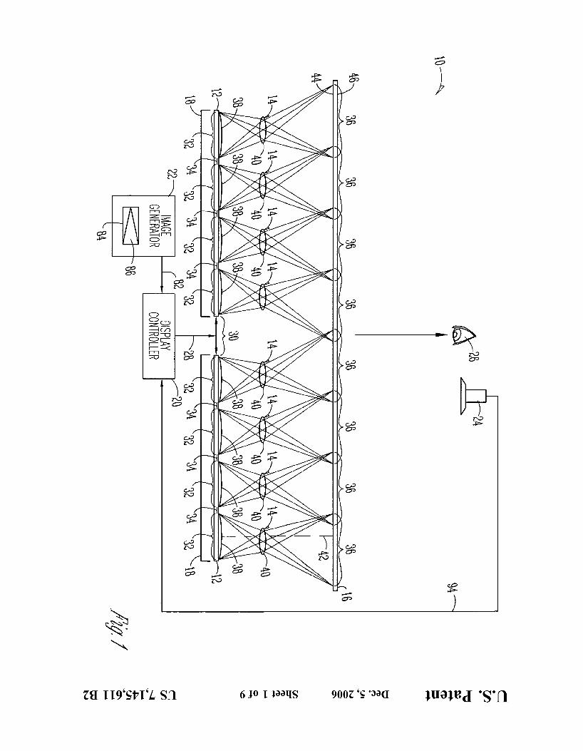
50 FIG. 1 is a system block diagram showing a seamless tiled display system including multiple display devices (e.g., LCDs) tiled together via projection to produce a larger andor higher-resolution image in accordance with one embodiment of the invention;
FIG. 2 is a system block diagram showing a seamless tiled display system including multiple display devices (e.g., LCDs) tiled together via projection to produce a larger andor higher-resolution image in accordance with another embodiment of the invention;
FIG. 3 is a block diagram of an exemplary embodiment of a unit cell projector for the tiled display system of FIG. 1, including a backlight system employing fiber bundles;
FIG. 4 is a block diagram showing another exemplary embodiment of a unit cell projector for the tiled display
65 system of FIG. 1, including a light pipe backlight system; FIG. 5 is a simplified diagram showing the electronic and
optical image processing performed by the display controller
55
60

US 7,145,611 B2 3 4
and optics shown in FIG. 1, wherein a desired image modular construction of system 10 allows for the modular undergoes several intermediate processing steps before construction of a display having any pixel count, and being displayed on the screen; decouples the ultimate size and resolution of the display
FIG. 6 is a simplified block diagram illustrating one from current manufacturing and yield limitations. exemplary optical system for projecting an image displayed 5 Gap 30 represents a space between adjacent display on one of the display devices of FIG. 1 onto a screen; devices 12 that may be filled with components for mounting
FIG. 7 is a simplified block diagram illustrating another display devices 12 within tiled display system 10. For exemplary optical system for projecting an image displayed example, interconnects, adhesives, seals or mechanical on one of the display devices of FIG. 1 onto a screen; alignment components (not shown) may be located in gap 30
FIG. 8 is a simplified block diagram illustrating another i o between adjacent display devices 12. In one embodiment, exemplary optical system for projecting an image displayed the width of gap 30 is the same or substantially the same as on one of the display devices of FIG. 1 onto a screen; the width of the gaps of known tiled display systems
FIG. 9 is a side view of one embodiment of an apparatus constructed by physically joining an array of FPD tiles for mounting and aligning an array of ball lenses; and together, with adjacent FPD tiles placed into close physical
FIG. 10 is a side view of another embodiment of an 15 abutment. For example, in one embodiment, adjacent dis- apparatus for mounting and aligning an array of ball lenses. play devices 12 are separated by a 12 mm gap. Thus, gap 30
would result in a visually disturbing seam if display devices DETAILED DESCRIPTION 12 were viewed directly by viewer 26. However, system 10
uses projection to eliminate the gap 30 between adjacent In the following detailed description, reference is made to 20 display devices 12 from disturbing the image on Screen 16.
the accompanying drawings, which form a part hereof, and Each display device 12 is subdivided into a plurality of in which is shown by way of illustration specific embodi- sections 32, and each section 32 is configured to display a ments in which the invention may be practiced. These sectional image. As described in reference to FIG. 5, display embodiments are described in sufficient detail to enable controller 20 accounts for the subdivision of display devices those skilled in the art to practice the invention, and it is to 25 12 (electronically, or using a software program) when gen- be understood that the embodiments may be combined, or erating display control signals 28 so that, when display that other embodiments may be utilized and that structural, control signals 28 are applied to display devices 12, sections logical, optical and electrical changes may be made without 32 display appropriate sectional images that can then be departing from the spirit and the scope of the invention. The projected and merged into a single desired image. In the following detailed description is, therefore, not to be taken 30 embodiment ofFIG. 1, each display device 12 is subdivided in a limiting sense, and the scope of the present invention is into four (4) sections 32 along the x-axis (i.e., horizontally), defined by the appended claims and their equivalents. and may further be subdivided along the y-axis (i.e., into the
Referring to FIG. 1, an exemplary seamless tiled display paper). Alternatively, each display device 12 may be subdi- system 10 in accordance with the present invention includes vided into other integral numbers (i.e., 2, 3, 4, etc.) of a plurality of display devices 12, a plurality of lens assem- 35 sections along either the x or y-axis. In this embodiment, a blies 14, a screen 16, a plurality of backlight assemblies 18, dead-band region 34 is also defined between each pair of a display controller 20, an image generator 22, and a detector adjacent sections 32 on display devices 12. As described 24. Tiled display system 10 is configured to generate a below, while the sectional image displayed on each section seamless, tiled image which is viewable by a viewer 26 32 is projected onto Screen 16, any images that appear in located in front of screen 16. 40 dead-band regions 34 will not be projected onto screen 16.
Each display device 12 is capable of generating an image Thus, any pixels within dead-band regions 34 will not be in response to display control signals 28 received from used. display controller 20. In one embodiment, each display One of lens assemblies 14 is optically coupled to each of device 12 comprises a flat-panel display (FPD), such as an sections 32 of each of display devices 12 to project the active-matrix or passive liquid-crystal display (LCD), a 45 sectional image displayed on that section onto screen 16. plasma display, an organic light-emitting diode (OLED) These images, referred to as projected sectional images, are display, etc. In another embodiment, each display device 12 projected onto screen 16 at screen sections 36. As shown in comprises a non-FPD, such as a cathode ray tube (CRT) FIG. 1, these projected sectional images may overlap. display, a projection display, etc. Each display device 12 In one embodiment, each lens assembly 14 includes a includes an array of pixels, and may be a monochrome (Le., 50 field lens 38 and a projection lens 40. Each field lens 38 is gray-scale) or a color display. A variety of FPD and non- located adjacent to one section 32 of display device 12, and FPD displays are commercially available in a variety of is optically coupled to that section 32 to focus light passing sizes and resolutions. In one embodiment, each display through that section onto a respective projection lens 40. device 12 comprises a Samsung SyncMaster 700 TFT panel, Without field lens 38, the light passing through that section which has 1280x1024 pixels in a 338x270 mm viewable 55 32 of display device 12 would spread out, and only a area, for a pixel pitch of 3.8 pixelsimm. However, other relatively small portion would reach projection lens 40. The display devices may also be used in system 10. focal length of each field lens 38 will be determined by the
Display devices 12 are arranged as an array of co-planar design of system 10. Each projection lens 40 is supported display “tiles”, with a gap 30 being located between each between its respective field lens 38 and screen 16, and is pair of adjacent devices. Although only two display devices 60 configured to project the light provided by that field lens 38 12 (arranged in a 2x1 array) are shown in FIG. 1, tiled onto screen 16. Thus, each field lens 38 focuses a sectional display system 10 may include any number of display image onto its projection lens 40, and each projection lens devices 12 that are arranged in any size array (i.e., any mxn 40 projects that image onto screen 16 to form a projected array of display devices 12, wherein m and n are any positive sectional image. integers). Thus, system 10 is a scalable and modular display 65 The plurality of lens assemblies 14 are configured to system since the number of display devices 12 can be merge the projected sectional images to form a seamless selected to meet the needs of a particular application. The tiled image on screen 16. To form this image, lens assem-

US 7,145,611 B2 5
blies 14 provide a combination of magnification having a magnitude of greater than 1 (e.g., +1.1; -1.1) and sideways shifting. In particular, lens assemblies 14 provide magnifi- cation such that the projected sectional images on screen 16 are larger than the corresponding sectional images on dis- play devices 12. By providing such magnification, adjacent projected sectional images can be merged together while eliminating any visual disturbance resulting from the dead- band region 34 between each pair of adjacent sections 32 (which are not projected onto screen 16). Such magnifica-
6 when the left edge of field lens 38 is aligned with the left edge of section 32, field lens 38 and projection lens 40 would each share a common normal axis. Then, any excess portion of field lens 38 extending over the right edge of section 32
Referring to FIG. 2, a tiled display system 50 in accor- dance with an alternative embodiment of the present inven- tion is shown. The components and structure of system 50 are generally the same as those of system 10, with differ-
i o ences in the subdivision of each display device 12, and the
5 would be cut off.
tion also helps eliminate any visual disturbance resulting parameters of lens assemblies 14. In particular, the width of from the gap 30 which separates adjacent display devices 12. the dead-band regions 34 defined between each pair of The amount of magnification will depend on the particular adjacent sections 32 on display devices 12 is now substan- design of tiled display system 10, but will be greater than lx . tially equal to the width of the gap 30 between devices 12,
Lens assemblies 14 also provide sideways shifting. In 15 and the lens assemblies 14 are now configured to merge the particular, at least one lens assembly 14 is configured to projected sectional images to form a seamless tiled image on provide a shift so that the projected sectional image on screen 16 using magnification, but without using sideways screen 16 is shifted sideways with respect to an axis normal shifting. to the corresponding sectional image. Such a normal axis 42 Lens assemblies 14 of system 50 provide magnification is shown in FIG. 1 for the right-most lens assembly 14 only. 20 such that the size of each projected sectional image on In the embodiment of FIG. 1, shifts to the left or right are screen 16 is equal to (or greater than) the size of the implemented by shifting or offsetting projection lenses 40 to corresponding sectional image on the display device 12 plus the left or right of the axis normal to the respective section the size of the dead-band region 34. If the projected sectional 32. Since this results in the object sections (Le., the sectional images are greater than this sum, the projected sectional images) being shifted to one side of the projection lens axis 25 images will overlap. Also, the projection lenses 40 of lens (Le., the axis normal to the projection lens), the image assemblies 14 are no longer offset with respect to the axis 42 sections (i.e., the projected sectional images) are shifted to that is normal to the corresponding sectional image, thereby the opposite side of the projection lens axis. Thus, for eliminating the shifts provided by the lens assembly con- example, since projection lens 40 of the right-most lens figurations shown in FIG. 1. Thus, since the width of assembly 14 in FIG. 1 is shifted to the right, the respective 30 dead-band regions 34 is now substantially equal to the width projected sectional image on screen 16 is also shifted to the of gap 30, and because the amount of magnification is right with respect to its corresponding sectional image on sufficient to bridge the dead-band regions 34, the amount of section 32. magnification is also sufficient to bridge gap 30. Therefore,
As shown in FIG. 1, some of lens assemblies 14 are neither dead-band regions 34 nor gap 30 will cause a visual configured to provide a right shift such that the respective 35 disturbance on screen 16. projected sectional image is shifted right with respect to an In FIG. 2, each section 32 is shown as being substantially axis normal to the corresponding sectional image, while the same size as deadbands 34 and gap 30. This configura- others of lens assemblies 14 are configured to provide a left tion disadvantageously wastes a relatively large percentage shift. For example, the lens assembly 14 on the left side of of pixels (since each unused dead-band 34 is as large as each gap 30 is configured to provide a right shift, while the lens 40 used section 32). Alternatively, each section 32 may be assembly on the right side of gap 30 is configured to provide defined to be larger than dead-bands 34 and gap 30 (with a left shift. By configuring these two lens assemblies 14 dead-bands 34 and gap 30 still being substantially the same adjacent to gap 30 to shift the respective projected sectional size), thereby decreasing the percentage of pixels in display images sideways towards each other, any visual disturbance devices 12 that will not be used. System 10 shown in FIG. resulting from gap 30 can be eliminated from the tiled 45 1 may be modified to create such a system by mounting the image.
Thus, by configuring lens assemblies 14 to provide an appropriate amount of magnification in combination with appropriate amounts and directions of sideways shifting, the projected sectional images are merged together to form a single, seamless tiled image on screen 16. The combination of magnification and shifting eliminates visual disturbances that would otherwise result from the dead-band regions 34 between each pair of adjacent sections 32, and from the gap 30 which separates adjacent display devices 12. By choosing an appropriate combination, dead-band regions 34 and gap
display devices 12 closer together such that gap 30 has substantially the same width as dead-bands 34, eliminating the offsets of projection lenses 40 to eliminate any shifts, and changing the magnification that is provided by each lens
50 assembly 14 to provide an appropriate amount of overlap. Although each lens assembly 14 is depicted in FIGS. 1
and 2 as being an optical cell with both a field lens and a projection lens, other forms of optical cells may be used. For example, an optical cell including only a single projection
55 lens configured to project the light coming through each section 32 of display device 12 onto screen 16 may be used.
30 can be bridged without wasting a large percentage of the Such a lens could be placed relatively close to the respective pixels located within the dead-band regions 34. section 32 to aid in collecting light. Other optical cells, with
In another embodiment, the optical axis of each field lens other numbers and types of optical lenses, may also be used. 38 is the same as the optical axis of its respective projection 60 In two embodiments of the present invention, each section lens 40. The optical axis of lenses 38 and 40 can be aligned 32 of display devices 12 forms a square, or a rectangle. In by, for example, increasing the size or width of field lens 38, another embodiment, each section 32 forms a hexagon. aligning the axis of field lens 38 with the axis of projection Making each section 32 a hexagon may result in tighter lens 40, and then cutting off any portion of field lens 38 that packaging and smaller image circle requirements, thus goes beyond an edge of its respective section 32. Referring 65 resulting in a simpler design. In the hexagon embodiment, to the right-most section 32 shown in FIG. 1, for example, each display device 12 will include half and quarter hexa- field lens 38 would be made wider than section 32 such that, gons surrounding the edges. The gaps may be filled from the

US 7,145,611 B2 7
adjacent display device, or each lens may be cut in half (or may not require electronic distortion correction may be in quarters for the corners) with a mirror placed between the used. Since the optical design can be simple, and the display devices 12 (so that the image associated with each performance requirements for each lens can be relaxed, it display device 12 will come only from that display device). may be possible to make the lenses out of molded plastic. Alternatively, shapes other than these may be used for each 5 The use of molded plastic lenses would be advantageous in section of display devices 12. terms of cost, weight and ease of assembly. It is also possible
Screen 16 comprises a rear projection screen having a rear to mold arrays of lenses for each display device 12, thereby side 44 and a front side 46. The sectional images from reducing the complexity of assembly. It may also be possible display devices 12 are projected onto rear side 44 by lens to use identical lenses in different locations for each subdi- assemblies 14, and the resulting tiled image is viewable by i o vision. For example, a three-lens system that requires only viewer 26 from front side 46. two molds could be used.
In one embodiment, the tiled image is used as the object for a high-magnification projection lens. The advantages of this approach include the thin size of the total image engine, and the ability to package the tiled, sensitive-to-motion parts 15 in one rugged box.
one advantage of the present invention is that tiled display system 10 can be made thin in comparison with
Backlight Assemblies
Referring back to FIG. 1, tiled display system 10 may also include a backlight assembly 18 optically coupled to each of display devices 12, if required by devices 12. Each backlight assembly 18 includes one or more sources that generate light
previous display systems due to the tradeoff between the that is applied to the associated display device 12. If the number of lens assemblies 14 provided for each display 20 display device is an LCD, for example, the LCD includes a device 12, and the depth of system 10. The practical field of plurality of light valves that are selectively clear or opaque, view for each projection lens is limited, which requires that under the control of display control signals 28 from display the distance from the projection lens to the display device be controller 20. When a particular light valve is clear, the light proportional to the size of the object image (i.e., the sec- from the backlight assembly 18 passes through. However, if tional image at section 32) for that lens. Thus, by decreasing 25 the light valve is opaque, the light from the backlight the size of the sectional images and increasing the number assembly 18 is blocked. Thus, by generating appropriate of projection lenses needed to cover display devices 12, the display control signals 28, display controller 20 is capable of
proportionately reduced. Therefore, the depth of tiled dis- to generate an image on those devices 12. play system 10 can be reduced, within practical limits, 30 In one embodiment, each backlight assembly 18 com- simply by increasing the number of lens assemblies 14, with prises a florescent light and a cavity, with the cavity being
distance from those lenses to the display devices can be selectively controlling the light valves of display devices 12
each lens assembly covering a smaller section 32. For example, ifthe number of lens assemblies 14 shown in FIG.
used to distribute the light generated by the florescent light onto the back of associated display device 12. While such a
1 was increased from four to eight per display device, and backlight assembly is very simple and can advantageously the size of each section was cut in half, then the thickness of 35 be made thin, the resulting backlight may not be efficient. In tiled display system 10 could be cut roughly in half. another embodiment, a single light source provides light to
Another advantage of tiled display system 10 is that each multiple display devices 12. projection lens 40 covers only a relatively small area. As the In another embodiment, each backlight assembly 18 is field of view for each lens 40 is decreased by making the subdivided into a plurality of backlight channels, with each subdivisions smaller, the minimum resolution that each lens 40 channel configured to provide backlighting for one section 40 must support decreases. Thus, the performance require- 32 of the corresponding display device 12. The subdivision ments of lenses 40 may be significantly relaxed in compari- of the backlighting scheme may thus match the above- son with systems that use only a single projection lens for described subdivision of the projection scheme. By subdi- each display device. Also, since each subdivision has less viding the backlight into multiple channels, the area covered area, each subdivision requires less light. Thus, the light 45 by each backlight channel can be significantly reduced as source for each subdivision can advantageously be made compared to an undivided backlight. Since backlight assem- smaller. Further, since the image of the source in each blies require a minimum useful length to provide a desired projection lens is smaller, the diameter of each projection level of uniform backlighting for a given output size, reduc- lens can be made smaller, thus resulting in a lighter and ing the area covered by each backlight channel can result in cheaper design for the projection lenses. 50 a reduction in the thickness of the backlight assembly. This
Still another advantage of tiled display system 10 involves reduction in the thickness of the backlight assembly can the ease of distortion correction due to the subdivision of further reduce the thickness of the overall tiled display each display device 12 into smaller sections. For a single- system 10. projection lens solution with a 1280x1024 pixel display Referring to FIG. 3, an exemplary embodiment of a “unit panel, distortion of only 0.06% would cause an error of half 55 cell” projector 60 is for use with a tiled display system of a pixel in the comer. However, by subdividing the panel including a backlighting system employing fiber bundles. into a plurality of 100x100 pixel sections, each projection Projector 60 is a “unit cell” projector since it is configured lens could have almost 1% distortion and still have an error to project one section 32 of display device 12 onto screen 16. of half of a pixel. By making the sections smaller, the The tiled display system would include an array of unit cell acceptable amount of distortion could be made even larger. 60 projectors 60 for each display device 12. Projector 60 Distortion can be corrected to a desired level simply by provides a backlight channel 62 for each section 32 that using an optical surface substantially removed from the includes a fiber bundle 64 and a condenser 66. Fiber bundle aperture stop of the lens. Further, by using lens assemblies 64 is configured to communicate light received from a light which provide magnification having a magnitude of close to source 68 (e.g., an arc lamp, LED, etc.) onto condenser 66, 1 (e.g., +1.1; -l.l), an optical design with a high degree of 65 and condenser 66 is configured to concentrate the light symmetry can be used. Thus, odd aberrations such as received from light source 68 via fiber bundle 64 onto the distortion will be small, and a simple optical system which respective section 32 of display device 12. Light passing

US 7,145,611 B2 9
through this section 32 is focused by field lens 38 onto projection lens 40, and is projected onto screen 16 to form a projected sectional image viewable by viewer 26.
In one embodiment where sideways shifting is used with unit cell projectors 60, the optical axis of condenser 66, field lens 38 and projection lens 40 of each projector 60 are the same. This is done in a manner similar to that described above for aligning the optical axis of field lens 38 and its respective projection lens 40 in the embodiment of FIG. 1.
Referring to FIG. 4, another embodiment of a “unit cell”
10 display signals 82 received from image generator 22. Image generator 22 is any device which generates signals 82 indicative of a desired image, such as image 84 (which may, for example, be a pennant 86). Thus, image generator 22
5 may be a computer system configured to generate images. Display controller 20 processes display signals 82 to form display control signals 28, and may be implemented in hardware or software. For example, display controller 20 may be implemented as a hardware circuit external to image
i o generator 22, as an image-processing circuit board mounted projector 70 is for use with a tiled display system including internally to image generator 22, or as a software program a backlighting system employing tapered light pipes. Pro- executed by image generator 22. Exemplary processing jector 70 provides a backlight channel 72 for each section 32 steps performed by display controller 20 are described in of display device 12, with each channel 72 including a light reference to FIG. 5. guide 74 and a tapered light pipe 76. Light guide 74 is part 15 Referring to FIG. 5, and working from bottom to top, of a system for distributing light from light source 68 to light display controller 20 receives display signals 82 indicative pipe 76. Tapered light pipe 76 uses the principle of internal of desired image 84 from image generator 22. In this reflection to obtain a desired level of light uniformity at its example, desired image 84 comprises pennant 86. Then, exit pupil 78. The minimum length of light pipe 76 from display controller 20 subdivides desired image 84 into a entrance pupil 80 to exit pupil 78 that is required to obtain 20 number of panels in accordance with the arrangement of a desired level of light uniformity is relatively small due to display devices 12 in tiled display system 10. For example, the subdivision of the backlighting system. Since the tiled since tiled display system 10 includes two display devices display system would include an array of unit cell projectors 12 along the x-axis, as shown in FIG. 1, display controller 70 corresponding to the array of sections 32 on each display 20 subdivides desired image 84 into two panels, as shown at device 12, there would be an array of light pipes 76 for each 25 reference numeral 88 in FIG. 5. In this example, these two device 12. The light passing through the respective section panels now include the left and right portions of pennant 86. 32 of display device 12 is focused by field lens 38 onto Then, display controller 20 subdivides each panel of projection lens 40, and is then projected onto screen 16 to desired image 84 into a number of sub-panels in accordance form a projected sectional image. with the number of sections 32 defined on each display
A number of methods may be used to distribute light to 30 device 12. For example, since each display device 12 the array of light pipes 76 on each display device 12. For includes four sections 32, each panel of desired image 84 is example, light source 68 may comprise a single light source subdivided into four sub-panels. To account for dead-band (which may be monolithic, or may include a plurality of regions 34 between each pair of adjacent sections 32 of light sources) for each display device 12, or may include display device 12, display controller 20 also inserts a dead- multiple light sources for each display device 12. The light 35 band region between each pair of adjacent sub-panels. The guide 74 may comprise a separate component for each light pixels in these dead-band regions will not be projected onto pipe 76, or may include a single component used for guiding screen 16 by lens assemblies 14. Also, since each lens light to a plurality of light pipes 76. Light guide 74 may assembly 14 is configured to reverse (Le., rotate) each include, for example, fiber bundles, solid light guides such sectional image as that image is optically projected from as liquid light guides or large plastic fibers, or slab 40 display device 12 to screen 16, display controller 20 also waveguides cut from one original piece. Alternatively, light guide 74 may be omitted, with light from light source 68 being coupled directly to light pipe 76.
By using tapered light pipes 76, the backlighting system can apply well-collimated light (i.e., light having relatively 45 small angles) to display device 12. Since this will result in the light passing through display device 12 being well collimated as well, field lens 38 can focus this light onto a relatively small spot where this light goes through projection lens 40. Thus, the design of projection lens 40 can be made 50
reverses each sub-panel. Display controller 20 then gener- ates display control signals 28 which, when applied to display devices 12, generate images on display devices 12 as shown at reference numeral 90 in FIG. 5. If these images were viewed directly, viewer 26 would see four sectional images on each display device 12, with each pair of adjacent sectional images being separated by a dead-band region, and with each sectional image reversed.
Alternatively, if lens assemblies 14 were configured to project the sectional images without reversing these images,
simpler due to its smaller aperture. the display controller would not reverse each sub-panel. In another embodiment, a light source could be placed Once the sectional images are displayed on display
behind a lens, and the lens could be configured to control the devices 12, lens assemblies 14 operate to project these size and numerical aperture of the backlight. Light sources sectional images onto screen 16 to form projected sectional which do not require any conditioning could also be used, 55 images. These projected sectional images are merged by such as light-emitting diodes (LEDs). In another embodi- being magnified and (possibly) shifted to form the single ment, one or more slab waveguides that have extraction dots tiled image shown at reference numeral 92 of FIG. 5. Thus, could be positioned behind display devices 12, with each the tiled image shown at reference numeral 92 is the same waveguide covering a portion of one display device 12, an as the desired image at reference numeral 84. entire display device 12 or multiple display devices 12. 60 The particular processing performed by display controller These dots would then act as the source for light pipes, 20 will depend upon the parameters of tiled display system lenses, or other conditioning optics. 10, such as the arrangement of display devices 12, the
subdivision of display devices 12 into sections, and the dead-band 34 between each section.
As suggested by FIG. 5, another advantage of projecting subdivisions of display devices 12 is the natural division of the processing workload. This natural division means that
Display Controller 6 5
Referring back to FIG. 1, display controller 20 is config- ured to generate display control signals 28 in response to
US 7,145,611 B2 11 12
parallel processing may be easily implemented for display projection optics with a narrow field of view (i.e., small device blocks, for each display device, for multiple subdi- angles). It may also be possible to use a single or dual-sided visions of each display device, or for each individual sub- lenticular prescreen to remove the shift variance, or a fiber division. Since many sections may require the same type of faceplate, or a screen that has small grooves etched into its processing, pipelining may be used. If there are several steps 5 back surface. The vertical surfaces made by the grooves will involved in processing each subdivision, a separate proces- reflect the light entering each post, so the output from each sor may be used to perform each step, thus allowing for the post will have light coming from up to four directions, use of several relatively simple processors in series to resulting in the equivalent of overlap taking place on the perform the work of fewer relatively complex processors. sub-pixel level.
10 Distortion Control EXAMPLES
Distortion refers to errors that may occur between the Other exemplary optical systems for use in the present actual locations of pixels on screen 16, and the desired invention are shown in FIGS. 6-8. The systems in the locations of the pixels. As indicated above, the subdivision 15 examples of FIGS. 6 and 7 are configured to project the of each display device 12 may allow any distortion correc- sectional images displayed on one of display devices 12 onto tion to be performed optically, thus eliminating the need for screen 16. Thus, a tiled display system would use one of electronic distortion control. If, however, it is not desirable these optical systems per display device 12. The optical or suficient to correct for distortion optically, electronic system shown in FIG. 8 is configured to project one sec- distortion correction may be used. Generally, electronic 20 tional image on one of display devices 12. Thus, a tiled distortion correction involves generating feedback signals display system would use a plurality of these unit optical representative of the distortion, and using the feedback cells per display device 12. signals to cancel out the distortion. In creating these examples, a number of design assump-
To provide for electronic distortion correction, tiled dis- play system 10 may include detector 24, which is configured to detect the tiled image produced on screen 16, and to generate feedback signals 94 used by display controller 20 to correct for any distortion. In one embodiment, display controller 20 generates signals 28 to display a particular pattern (e.g., a grid of dots, gridlines, etc.) on screen 16. Detector 24 senses the resulting pattern produced on screen 16, and generates feedback signal 94. Display controller 20 uses feedback signal 94 to characterize any errors between
tions and constraints were used, including: each display 25 device 12 will comprise a Samsung SyncMaster 700 TFT
panel, which has 1280x1024 pixels in a 338 mmx270 mm viewable area, for a pitch of 3.8 pixelsimm; a 12 mm dead-band will be around each LCD; root-mean-square (RMS) spot size (diameter) will be less than the pixel size;
30 the total thickness of the system will be less than 100 mm (not including the backlight); distortion will be limited to half of a pixel; the entrance pupil will have a minimum diameter of four mm; the backlight design will be matched
the commanded and the actual patterns, and introduces an to the lens pupil; and the lenses will be restricted to singlets equal and opposite amount of error to cancel out the distor- 35 or air-spaced doublets. The actual design assumptions and tion. constraints would depend upon the particular application,
In another embodiment, detector 24 comprises a move- and may be the same as or different from those set forth in able camera or detector configured to generate a detection this paragraph. For example, in one embodiment, triplet signal when the camera passes over the location of a dot lenses could be used instead of doublet lenses. within a grid of dots, with the location of each dot deter- 40 In each of these three examples, a symmetrical optical mined by the location of the detector when the dot is system was selected based upon a geometrical analysis detected. In another embodiment, with detector 24 in a fixed indicating that only minimal magnification (e.g., 1.1~) was location, one line is turned on at a time, and the location of required, and based upon the need for excellent distortion that line on screen 16 is detected. Then, when it is desired control. By having only a small angle cone of light going to to create a line at a location on screen 16, the appropriate line 45 each image point, a slight defocus can achieve the desired is turned on. This latter embodiment may provide faster magnification. By choosing a symmetrical optical system, distortion correction since detector 24 does not move. distortion is minimized, thereby eliminating the need for
In still another embodiment, detector 24 comprises a complex image warping electronics. The absence of all pixelated camera configured to take a picture of screen 16. aberrations of the field except astigmatism and field curva- The pixels of display devices 12 and the camera will form 50 ture allows for a wide-angle design. Also, by making both a Moirk pattern (Le., since the pixelated camera and display lenses in a doublet of identical lenses, costs can be reduced devices 12 both have a periodic structure, superimposing via commonality of parts and because only one mold would these structures will yield a low-frequency periodic structure be required for plastic lenses. Also, where plastic lenses are showing the difference between these two frequencies). A used, manufacturing costs can also be reduced by molding variety of schemes can be used to find the phase map from 55 an array of plastic lenses for projecting an array of sectional a fringe pattern, including fringe center detection and phase images onto the screen. shifting algorithms. The phase information may then be Referring to FIG. 6, an exemplary optical system 100 converted into a distortion map, and this map may then be includes five projection lenses 102 arranged to cover the inverted by display controller 20 to produce a pre-warped longer (338 mm) side of the LCD, with each lens covering image. 60 ?A of the length (67.6 mm). System 100 also includes four
Besides distortion, viewing angle variations in the lumi- projection lenses 102 arranged to cover the shorter (270 nance may create another artifact that may need to be mm) side of the LCD, with each lens covering ?A of the controlled. This artifact arises from the shift variant behavior width (67.5 mm). Thus, to cover the entire LCD, system 100 of projection screens. Methods for controlling this artifact includes a total of 20 projection lenses 102 arranged in a 5x4 may include using a relatively large amount of overlap 65 array, with each lens covering a substantially square area. between adjacent tiles on screen 16 (which will give a Optical system 100 was designed to minimize the number of gradual transition from one side to the other), or using projection lenses per LCD. In system 100, a display surface

US 7,145,611 B2 13 14
104 of device 12 forms the object, with an infinite radius of Referring to FIG. 8, another exemplary optical system curvature. Each projection lens 102 is an air-spaced sym- 140 uses a ball lens 142 for projecting each sectional image metrical doublet, including a first lens 106 having an outer on display device 12 onto screen 16. In this design, the radius of curvature of 6,779 and an inner radius of angular extent of the light coming from the LCD may be
of 7,272 mm, and a second lens 108 having an 5 limited by the backlight assembly. While this may increase inner radius of curvature of -7.272 nun and an outer radius the complexity of the backlight assembly, this of of -6,779 nun, In this embodiment, projection may be more than offset by cost reductions in the projection
Optics and manufacturing process since inexpensive, and mounting and alignment considerations are through each projection lens 102, and an image surface 112
i o simpler. By using a ball lens, distortion, coma and astigma- of screen 16, each have an infinite radius of curvature. tism are removed, and the only third-order aberrations Distance a between surface 104 and the outer surface of first present are spherical and field curvature, In one embodi- lens lo6 is 37'31 Distance between the Outer and ment, ball lens 142 is an acrylic ball, or section thereof. her surfaces Of first lens lo6 is 5.414 mm. Distance Distance a from a display surface 144 of device 12 to surface
2.532 nun. Distance between stop and the her 146 to opposite surface 148 of ball lens 142 (Le., the surface of second lens 108 is 2.535 nun. Distance e between diameter of ball lens 142) is 36,0 mm, Distance from the inner and outer surfaces of second lens 108 is 5.414 nun, surface 148 to an image surface 150 of screen 16 is 35,07 and distance f between the outer surface of second lens 108 nun, Thus, the thickness of system 140 (i,e,, from display and image surface '12 is 41.89 nun. Thus, the Overall 20 surface 144 to image surface 150) is about 101.5 mm. Note
entrance pupil is 4 nun or smaller, image quality will be surface 104 to image surface 112) is about 95.1 nun. Referring to FIG. 7, another exemplary optical system acceptable over a 50 nun circle.
120 includes 12 projection lenses 122 arranged to cover the Referring to FIG, 9, an apparatus 160 for mounting and longer (338 mm) side ofthe LCD, With each, lens covering 25 aligning an array of ball lenses 162 for use in a display %2 ofthe length (28.2 nun). System 100 also includes Seven device in accordance with one embodiment of the invention Projection lenses 122 arranged to cover the h r t e r (270 includes a first plate 164 and a second plate 166. Plate 164 nun) side of the LCD, With each lens covering ?h of the has an array of circular holes 168 formed therein (e.g., by width (38.6 nun). Thus, to cover the LCD, system 120 drilling) and plate 166 has an array of circular holes 170 includes a total of 84 Projection lenses 122 arranged in a 30 formed therein (e.g.. by drilling). The diameters ofholes 168 12x7 array, each lens covering a rectangular area. In corn- and 170 is less than the diameter of each ball lens 162 so Parison With system 100, optical system 120 was designed that, when lenses 162 are sandwiched between plates 164 to limit the field of view for each projection lens. In system and 166, lenses 162 are held by plates 164 and 166. In one 120, a display surface 124 of device 12 forms the object, embodiment, the diameter of holes 168 is equal to the with an infinite radius of curvature. Each projection lens 122 35 diameter of holes 170, In another embodiment, the diameter is an air-sPaced symmetrical doublet, including a first lens of holes 168 is less than or greater than the diameter of holes 126 having an outer radius of curvature of 16.29 nun and an 170, ne diameter of holes 168 and 170 is large enough to inner radius of curvature of 60.07 nun, and a second lens 128 provide a suficiently bright image on the display, The having an inner radius of Curvature of -60.07 and an spacing of holes 168 in plate 164, and of holes 170 in plate outer radius of curvature of -16.29 111111. In this embodiment, 40 166, is configured to provide spacing of lenses 162 which is Projection lenses 122 are made of Polystyrene. A stop 130, appropriate for the particular configuration of the display passing through each projection lens 122, and image surface device, 132 of screen 16, each have an infinite radius of curvature. In one embodiment, mounting and alignment apparatus Distance a between surface 124 and the outer surface of first 160 is formed by providing plate 166, placing ball lenses lens 126 is 32.73 mm. Distance b between the Outer and 45 162 on top of plate 166, shaking plate 166 until the ball inner surfaces of first lens 126 is 12.50 mm. Distance C lenses 162 have fallen into holes 170 in plate 166, and then between the inner surface of first lens 126 and stop 130 is placing plate 164 on top of lenses 162. In this manner, ball 1.935 nun. Distance d between stop 130 and the inner lenses 162 are conveniently and inexpensively mounted and surface of second lens 128 is 1.935 nun. Distance e between aligned, the inner and outer surfaces of second lens 128 is 12.50 nun, 50 Referring to FIG. 10, another apparatus 180 for mounting and distance f between the outer surface of second lens 128 and aligning an array of cylindrical ball lenses 182 (only one and image surface 132 is 37.38 111111. The thickness of system shown) for use in a display device in accordance with one 120 (from display surface 124 to image surface 132) is about embodiment of the invention includes a plate 184. Lenses 99.0 nun. 182 have a spherical top 186, a spherical bottom 188 and a
By limiting the field of view for each projection lens 122 55 cylindrical middle portion 190. Lenses 182 may be formed, relative to that of system 100, system 120 may simplify the for example, by taking a core from a spherical ball. Plate 184 complexity of the backlight assembly, and decrease the has a thickness on the order of, but less than, the diameter likelihood of tiling non-uniformities due to screen properties of lenses 182 (Le., the distance from top 186 to bottom 188). in comparison to system 100. Further, by dividing the LCD Plate 184 has an array of holes 192 (only one shown) formed into smaller pieces, the performance requirements of pro- 60 therein (e.g., by drilling). Each hole 192 is formed by jection lenses 122 may be relaxed in comparison to those of drilling a first bore having a diameter D1 less than the projection lenses 102. This relaxation may allow looser diameter of cylindrical middle portion 190 completely tolerances, which may allow the lenses to be less expensive. through plate 184, and then drilling a second bore having a System 120 also has a larger entrance pupil for the light from diameter D2 slightly greater than the diameter of cylindrical display device 12. In one embodiment, the pupil has a 65 middle portion 190 partially through plate 184 in direction diameter of 6.4 mm, allowing 20% more light to pass 194 so as to leave an abutment 196 of plate 184 in hole 192 through. (e.g., by drilling the second bore only 90% through plate
lenses 102 are made of polystyrene, A stop 110, passing lenses are
between the inner Of first lens lo6 and stop 110 is 15 146 ofball lens 142 is 30.47 mm, Distance b from surface
thickness Of system loo (i.e.> the distance from that, provided the stop is formed by the backlight and the
US 7,145,611 B2 15
184). Then, lens 182 is placed into hole 192 until bottom 188 comes into contact with abutment 196. At this point, spheri- cal bottom 188 extends outwardly from the bottom of plate 184, and spherical top 186 extends outwardly from the top of plate 184. In one embodiment, an adhesive secures lens 182 in hole 192. In another embodiment, a thin plate (not shown) having an array of holes having a diameter less than the diameter of cylindrical middle portion 190 is mounted to the top of plate 184 to secure lenses 182 within plate 184. Thus, cylindrical ball lenses 182 are conveniently and inex- pensively mounted and aligned.
In another embodiment, the sides of a cylindrical ball lens are shaped inwardly from the spherical top and bottom of the lens towards the midpoint of the middle portion (e.g., similar to a core of an apple that has been eaten around the circumference). The middle portion is painted black to provide a cylindrical ball lens having an aperture in the center.
Conclusion
The above description is intended to be illustrative, and not restrictive. Many other embodiments will be apparent to those of skill in the art. For example, a tiled display system in accordance with the present invention may include dif- ferent size arrays of display devices, each display device may be subdivided into different numbers of sections, and different optical systems may be used to project each sec- tional image onto the screen. The amount of magnification andor shifting provided by the optical systems may also be different, as may the size of the dead-bands between sections andor gaps between display devices. The scope of the invention should therefore be determined with reference to the appended claims, along with the full scope of equivalents to which such claims are entitled.
What is claimed is: 1. A tiled display apparatus, comprising: a plurality of display devices, wherein each display device
is subdivided into a plurality of sections with each section separately configured to display a sectional image, each display device including a dead-band region between each pair of adjacent sections;
a screen; and a plurality of lens assemblies, wherein each lens assembly
is optically coupled to a corresponding one of the sections of each of the display devices to project the sectional image displayed on that section onto the screen, and the plurality of lens assemblies are config- ured to merge the projected sectional images to form a single tiled image, at least one lens assembly is con- figured to provide magnification having a magnitude of greater than 1 such that the respective projected sec- tional image on the screen is larger than the corre- sponding sectional image on the display device, wherein the lens assemblies provide magnification to merge adjacent projected sectional images together to eliminate the dead-band regions from the tiled image, at least one lens assembly being configured to provide a shift so the respective projected sectional image on the screen is shifted sideways with respect to an axis normal to the corresponding sectional image.
2. The apparatus of claim 1, wherein each display device
3. The apparatus of claim 2, wherein each display device
4. The apparatus of claim 1, wherein each display device
comprises a flat-panel display (FPD).
comprises a liquid-crystal display (LCD).
comprises a non-FPD.
5
10
15
20
25
30
35
40
45
50
55
60
6 5
16 5. The apparatus of claim 4, wherein each display device
is selected from the group consisting of a cathode ray tube (CRT) display and a projection display.
6. The apparatus of claim 1, wherein the screen comprises a rear projection screen having a rear side and a front side, and wherein the sectional images are projected onto the rear side and the tiled image is viewable from the front side.
7. The apparatus of claim 1, wherein each of the lens assemblies includes a projection lens for projecting the respective sectional image onto the screen.
8. The apparatus of claim 7, wherein each projection lens is symmetric.
9. The apparatus of claim 8, wherein each projection lens includes a doublet of identical lenses.
10. The apparatus of claim 8, wherein eachprojection lens includes a triplet of lenses.
11. The apparatus of claim 8, wherein eachprojection lens includes a ball lens.
12. The apparatus of claim 7, wherein each lens assembly also includes a field lens for focusing the respective sec- tional image onto the respective projection lens.
13. The apparatus of claim 12, wherein the projection lens of each lens assembly has an optical axis and the field lens of each lens assembly has the same optical axis.
14. The apparatus of claim 12, wherein the projection lens of each lens assembly has a first optical axis, the field lens of each lens assembly has a second optical axis, and the first and the second optical axis of at least one lens assembly are different.
15. The apparatus of claim 1, wherein each lens assembly includes a plastic lens.
16. The apparatus of claim 15, wherein the plurality of lens assemblies includes an array of plastic lenses for projecting an array of sectional images onto the screen.
17. The apparatus of claim 1, wherein adjacent display devices are separated by a gap, and at least one lens assembly adjacent to the gap is configured to shift the respective projected sectional image sideways with respect to the normal axis and towards the gap so as to eliminate at least part of the gap from the tiled image.
18. The apparatus of claim 17, wherein both of the lens assemblies adjacent to the gap are configured to shift the respective projected sectional images sideways towards each other so as to eliminate the gap from the tiled image.
19. The apparatus of claim 1, further comprising a plu- rality of backlight assemblies, each backlight assembly optically coupled to one of the display devices.
20. The apparatus of claim 19, wherein each backlight assembly provides a plurality of backlight channels, and each backlight channel is configured to provide a separate backlight for one of the sections of the corresponding display device.
21. The apparatus of claim 20, wherein each backlight channel includes a condenser for concentrating light received from a light source onto the section.
22. The apparatus of claim 20, wherein each backlight channel includes a fiber bundle for communicating light received from a light source onto the section.
23. The apparatus of claim 20, wherein each backlight channel includes a tapered light pipe for communicating light from a light source onto the section.
24. The apparatus of claim 1, further comprising means for distortion control.
25. Amethod of generating a tiled display, comprising the steps of
providing a plurality of display devices;
US 7,145,611 B2 17
subdividing each of the display devices into a plurality of separate display sections such that there is a dead-band region between each pair of adjacent sections on each display device;
displaying a sectional image on each section of each display device; and
projecting the sectional image displayed on each section of each display device onto a screen with the projected sectional images merged into a tiled image, wherein projecting the sectional image displayed on each sec- tion includes magnifying at least one of the sectional images such that the respective projected sectional image on the screen is larger than the corresponding sectional image on the display device and magnifying adjacent sectional images on either side of the dead- band regions to eliminate the dead-band regions from the tiled images the projecting step includes shifting at least one of the projected sectional images sideways on the screen with respect to an axis normal to the corre- sponding sectional image.
26. The method of claim 25, wherein the projecting step includes focusing the respective sectional image onto a projection lens for projecting the sectional image.
27. The method of claim 25, wherein the projecting step includes projecting an array of sectional images onto the screen using an array of plastic projection lenses.
28. The method of claim 25, wherein the providing step includes defining a gap separating adjacent display devices, and the projecting step includes shifting at least one pro- jected sectional image adjacent to the gap sideways with respect to the axis and towards the gap so as to eliminate at least part of the gap from the tiled image.
29. The method of claim 28, wherein the projecting step includes shifting a pair of projected sectional images adja-
18 cent to the gap sideways towards each other so as to eliminate the gap from the tiled image.
30. The method of claim 25, further comprising optically coupling a backlight to each of the sections of each of the display devices.
31. An apparatus for generating a tiled display, compris- ing:
10
15
20
25
30
a plurality of display devices; a screen; means for subdividing each display device into a plurality
of separate display sections such that each display device includes a dead-band region between each pair of adjacent sections;
means for displaying a sectional image on each section of each display device; and
means for projecting the sectional image displayed on each section of each display device onto the screen with the projected images merged into a tiled image, the projecting means including means for magnifying at least one of the sectional images so the projected sectional image on the screen is larger than the corre- sponding sectional image on the display device, and wherein the projecting means includes means for mag- nifying adjacent sectional images to merge adjacent projected sectional images together to eliminate the dead-band regions from the tiled image, the projecting means including means for shifting at least one of the projected sectional images sideways on the screen with respect to an axis normal to the corresponding sectional image on the display device.
* * * * *