united states steel corporation midwest plant portage, indiana · {b3687835.1} united states steel...
TRANSCRIPT
{B3687835.1}
United States Steel Corporation Midwest Plant Portage, Indiana
Wastewater Treatment
O & M Manual and Preventative Maintenance Program Plan
Effective Date: DRAFT 04-13-2018
U. S. Steel - O & M Manual/Preventative Maintenance Program Plan – Wastewater Treatment
TABLE OF CONTENTS
{B3687835.1} Table of Contents-i Rev. Date: 04/11/2018
Preface
Revision Log Distribution Log O & M Manual and Preventative Maintenance Program Plan
Introduction ................................................................................................................................ 2
I. National Pollutant Discharge Elimination System (NPDES) Permit Overview ..................... 2
I.A. NPDES Part I: Limits, Monitoring and Reporting Requirements .................................. 2
I.B. NPDES Part II: Standard Conditions ........................................................................... 3
I.C. NPDES Part III: Other Requirements .......................................................................... 3
I.D. NPDES Part IV: Cooling Water Intake Structures........................................................ 3
II. Description of Wastewater Treatment and Associated Process Equipment ........................ 4
II.A. Total Treatment Overview ............................................................................................ 4
II.B. Oil Pretreatment System .............................................................................................. 4
1. Process Description ................................................................................................. 4
2. Process Flow Diagrams ............................................................................................ 5
3. Equipment Description ............................................................................................. 5
4. Operating Procedure(s) ............................................................................................ 6
5. Preventive Maintenance Program ............................................................................ 6
7. Forms ....................................................................................................................... 6
II.C. Chrome Treatment Plant .............................................................................................. 6
1. Process Description ................................................................................................. 6
2. Process Flow Diagrams ............................................................................................ 7
3. Equipment Description ............................................................................................. 7
4. Operating Procedure(s) ............................................................................................ 7
5. Preventive Maintenance Program ............................................................................ 8
6. Forms ....................................................................................................................... 9
II.D. Final Treatment Plant ................................................................................................... 9
1. Process Description ................................................................................................. 9
2. Process Flow Diagrams ...........................................................................................10
3. Equipment Description ............................................................................................10
4. Operating Procedure(s) ...........................................................................................10
5. Preventive Maintenance Program ...........................................................................11
6. Forms ......................................................................................................................11
II.E. Sludge Dewatering......................................................................................................11
1. Process Description ................................................................................................11
2. Process Flow Diagrams ...........................................................................................12
3. Equipment Description ............................................................................................12
4. Operating Procedure(s) ...........................................................................................12
5. Preventive Maintenance Program ...........................................................................12
6. Forms ......................................................................................................................13
II.F. Zebra Mussel Control ..................................................................................................13
1. Process Description ................................................................................................13
2. Process Flow Diagrams ...........................................................................................13
3. Equipment Description ............................................................................................13
II.G. Job Descriptions - WWT Assigned Personnel .............................................................13
U. S. Steel - O & M Manual/Preventative Maintenance Program Plan – Wastewater Treatment
TABLE OF CONTENTS
{B3687835.1} Table of Contents-ii Rev. Date: 04/11/2018
1. Chrome Plant Operator – (Advanced Position) ........................................................13
2. Final Treatment Plant Operator – (Intermediate Position) ........................................14
3. Sludge Dewatering Plant Operator – (Advanced Position) .......................................14
4. Utilities Helper – (Entry Position) .............................................................................14
5. Instrument Repairman .............................................................................................15
6. Mechanical Repairman ............................................................................................15
7. Electrical Repairman ...............................................................................................15
8. Centrifuge Operator – (Contractor) ..........................................................................15
9. Zebra / Quagga Mussel Control Personnel – (Contractor) .......................................15
10. Chemical Supplier – (Contractor) ............................................................................16
11. Sample Collection and Analysis – (Contractor) ........................................................16
III. Laboratory Requirements ...............................................................................................16
IV. Recordkeeping Requirements ........................................................................................16
V. Plan for Inspection, Cleaning and Maintenance of Outfall Channels ..............................17
VI. Preventive Maintenance Program Plan...........................................................................17
VII. Review of O&M Plan ......................................................................................................17
Appendices
Appendix I.A. NPDES Permit Part I – Effluent Limits, Monitoring, & Conditions
Appendix I.B. NPDES Permit Part II – Standard Permit Conditions
Appendix I.C. NPDES Permit Section Part III – Other Requirements
Appendix I.D. NPDES Permit Section Part IV – Cooling Water Intake Structures
Appendix II Process Flow Diagrams
U. S. Steel - O & M Manual/Preventative Maintenance Program Plan – Wastewater Treatment
{B3687835.1} Preface
PREFACE
U. S. Steel - O & M Manual/Preventative Maintenance Program Plan – Wastewater Treatment
{B3687835.1} Preface
REVISION LOG
Revision Number Revision Date Sections Revised
U. S. Steel - O & M Manual/Preventative Maintenance Program Plan – Wastewater Treatment
{B3687835.1} Preface
DISTRIBUTION LOG
Copy Location Number of Copies at
Location Electronic or Hardcopy
U. S. Steel - O & M Manual/Preventative Maintenance Program Plan – Wastewater Treatment
{B3687835.1}
O & M Manual and
Preventative Maintenance Program
Plan
U. S. Steel - O & M Manual/Preventative Maintenance Program Plan – Wastewater Treatment
{B3687835.1} Page 2 Rev. Date: 04/11/2018
Introduction This Operation and Maintenance Manual and Preventative Maintenance Program Plan (Manual) for the Midwest Plant’s Wastewater Treatment Facilities is intended to satisfy the requirements set forth in the Consent Decree dated April 2, 2018. This document also supersedes and replaces the existing Chrome Plant Containment Trench Operating and Maintenance Plan. I. National Pollutant Discharge Elimination System (NPDES) Permit Overview Midwest is authorized to discharge into the waters of the State of Indiana under the National Pollutant Discharge Elimination System (NPDES) Permit No. IN0000337 (Permit). The State of Indiana is authorized by the United States Environmental Protection Agency (USEPA) to administer the NPDES program. The Indiana Department of Environmental Management (IDEM) is the state agency responsible for administering and enforcing Midwest’s NPDES permit. NPDES permits are issued for a 5-year period but can generally be administratively extended as long as the application for renewal was submitted complete and on time. The Permit is a legal document and all requirements, limits and conditions must be adhered to while the Permit is in effect. Any violation of Permit conditions could result in civil or criminal action. This section of the Manual contains a summary of Permit requirements. This is only a summary and is not intended to substitute for the actual language of the Permit. The actual Permit language should be consulted for compliance (see Appendix I). Generally speaking, the Permit consists of four parts, as described below in Parts I.A through Part I.D of this Manual. I.A. NPDES Part I: Limits, Monitoring and Reporting Requirements Part I of the NPDES permit contains the following subsections that pertain to the limits, monitoring and reporting requirements that apply to Midwest:
• Part I.A – Effluent Limitations and Monitoring Requirements – This subsection contains the numerical limits for the constituents to be monitored at each outfall.
• Part I.B – Narrative Water Quality Standards – This subsection details the narrative water quality standards such as oil sheens, odor, color, etc. that must be monitored.
• Part I.C – Monitoring and Reporting - This subsection further describes the discharge monitoring and reporting requirements within the Permit. The Midwest Facility uses a certified third-party laboratory to collect, analyze and report all required samples. Data is summarized on Daily Monitoring Reports (DMR) as well as Monthly Monitoring Reports (MMR), which are required to be submitted electronically each month. The DMR and MMR are signed by U. S. Steel prior to submittal to IDEM and USEPA.
• Part I.D – Storm Water Monitoring and Non-Numeric Effluent Limits – This subsection contains the non-numeric Permit conditions, including the inspection requirements associated with the Facility’s storm water discharges.
• Part I.E – Storm Water Pollution Prevention Plan (SWPPP) – This subsection outlines the required content and implementation of the Facility’s SWPPP.
• Part I.F – Chronic Biomonitoring Program Requirements – This subsection outlines the Permit’s whole effluent toxicity testing requirements and the components of the subsequent toxicity reduction evaluation schedule of compliance, as needed.
• Part I.G – Pollution Minimization Program – This subsection sets forth the goals and requirements of the pollution minimization program for applicable pollutants
U. S. Steel - O & M Manual/Preventative Maintenance Program Plan – Wastewater Treatment
{B3687835.1} Page 3 Rev. Date: 04/11/2018
• Part I.H – Toxic Organic Pollutant Management Plan – This subsection identifies the requirement for the Facility to submit a toxic organic management plan and also identifies the components of the plan.
• Part I.I – Reopening Clauses – This subsection outlines the circumstances under which the Permit may be modified or revoked.
• Part I.J – Reporting Requirements for Solvents, Degreasing Agents, Rolling Oils, Water Treatment Chemicals and Biocides – This subsection outlines the Facility’s annual requirement to report the quantity of certain chemicals that are used at the Facility and also the amount of those chemicals that may be present in any of the Facility’s outfalls.
• Part I.K – Schedule of Compliance – This subsection identifies the schedule of tasks required to achieve compliance with the effluent limitations for Lead and Nickel at Outfall 004.
Refer to Appendix I.A. for NPDES Permit Section Part I – Effluent Limits, Monitoring, & Conditions. I.B. NPDES Part II: Standard Conditions Part II contains the following standard conditions that apply to all NPDES permits, including the Facility’s Permit:
• Part II.A – General Conditions – This subsection includes descriptions of the duties to comply, mitigate adverse effects on the environmental and reapply for the Permit. It also covers civil penalties, causes for modifying, revoking or terminating a permit, toxic pollutant obligations, wastewater treatment plant operator certification requirements, and Facility inspections by IDEM.
• Part II.B – Management Requirements – This subsection pertains to the requirements for operating and maintaining treatment systems and also the procedures and conditions under which bypasses and upsets are permitted,
• Part II.C – Reporting Requirements – This subsection pertains to reporting requirements associated with planned changes to the Facility or its discharges, as well as other requirements regarding compliance/noncompliance reporting, signatory requirements and changes in the discharge of toxic substances.
Refer to Appendix I.B. for NPDES Permit Section Part II – Standard Permit Conditions. I.C. NPDES Part III: Other Requirements Part III of the Permit contains requirements regarding the discharges of thermal effluent and polychlorinated biphenyls (PCBs) Refer to Appendix I.C. for NPDES Permit Section Part III – Other Requirements. I.D. NPDES Part IV: Cooling Water Intake Structures Part IV of the Permit contains requirements that are associated with the cooling water intake structures located at the Midwest Facility. These requirements are primarily related to the Best Technology Available (BTA) determination and the associated requirements to submit certain reports and information to IDEM. Refer to Appendix I.C. for NPDES Permit Section Part IV – Cooling Water Intake Structures.
U. S. Steel - O & M Manual/Preventative Maintenance Program Plan – Wastewater Treatment
{B3687835.1} Page 4 Rev. Date: 04/11/2018
II. Description of Wastewater Treatment and Associated Process Equipment
II.A. Total Treatment Overview The Midwest wastewater treatment facilities are designed to handle the wastewater streams generated by the various production lines for flat rolled steel. These lines include:
• Pickle line for removal of oxides with acid;
• Tandem lines to reduce strip thickness;
• Electrolytic cleaning for oil removal;
• Annealing for increased steel ductility;
• Temper lines for increasing coil hardness;
• Galvanizing lines for zinc coating; and,
• Coating lines including tin and chrome plating. As shown on Figure MWE-04, the Midwest Plant has five wastewater treatment systems: (1) an Oil Pretreatment System, (2) a Chrome Treatment Plant (Chrome Plant), (3) a Final Treatment Plant (Final Treat), (4) sludge dewatering, and (5) zebra mussel control. As explained in greater detail below, oil-containing wastewater streams are discharged primarily to the Oil Pretreatment System where oil is separated through the API’s, decanting and centrifuge. The separated oil is sent offsite for recycling to a licensed oil processor. The wastewater flows from the oil separation system to the Final Treatment Plant. Wastewater systems that contain chromium are collected in dedicated conveyances that becomes the influent to the Chrome Treatment Plant. This facility reduces hexavalent chrome to trivalent chrome so that it can be removed from the wastewater. The effluent from this facility is discharged through NPDES Internal Outfall 204 and ultimately discharges through NPDES Outfall 004 into Burns Waterway. The remaining wastewater streams (non-chromium) and the discharge from the Oil Pretreatment System and sludge dewatering facilities flow into the Final Treat. Additionally, some backwash and non-contact cooling water is also sent to the Final Treat. Wastewaters entering the Final Treatment Plant are treated through this system to adjust pH, remove solids and remove any remaining oil. The effluent from this facility is discharged through NPDES Internal Outfall 104 and ultimately through NPDES Outfall 004 into Burns Waterway. The sludge dewatering facility receives underflow solids from the Final Treatment Plant and uses filter presses to dewater the sludge for disposal in the onsite permitted landfill (Greenbelt II). The wastewater from the pressed sludge/solids is returned to the Final Treatment Plant influent. Midwest also has a Zebra and Quagga Mussel control water treatment program. This treatment program is a process that chlorinates all the service water pumped into the plant beginning in June and ending in October to kill mussel veligers (larvae). The chlorinated service water is dechlorinated prior to discharge from the Midwest NPDES permitted outfalls. II.B. Oil Pretreatment System 1. Process Description
Wastewaters containing animal fat, vegetable oil, mineral oil and petroleum-based oils are processed through the Oil Pretreatment System (APIs) where oils are removed prior to discharge into the Final Treatment Plant.
U. S. Steel - O & M Manual/Preventative Maintenance Program Plan – Wastewater Treatment
{B3687835.1} Page 5 Rev. Date: 04/11/2018
Oily wastewaters flow into the Oil Interceptor 75,000-gallon Equalization (EQ) Tank. From here, the wastewater flows into the North Interceptor Mix Tank for additions of polymers and/or tannins to chemically aid oil separation. Effluent from the Mix Tank is split between the North Oil Interceptor’s East and West basins where oil is skimmed off and sent to the Oil Holding Tanks. The skimmed effluent wastewaters then flow to either the Final Treatment Plant or to the South Oil Interceptor. Effluent from the North Oil Interceptor to the South Oil Interceptor flows into the South Mix Tank that feeds the oily wastewaters into the South Oil Interceptor (Monroe) where oil is skimmed off and sent to the Oil Holding Tanks. The skimmed effluent wastewaters then flow into the Dissolved Air Filtration (DAF) units for additional oil removal. The oil removed in the DAF units are sent to the Oil Holding Tanks. DAF effluent wastewaters flow into the Final Treatment Plant. The Oil Holding Tanks (North and South) are heated to improve oil separation and the decant water is returned to the EQ Tank. The oil is pumped to a centrifuge for final oil separation. The centrifuged oil is collected in an Oil Storage Tank for offsite recycling at a licensed oil processing facility. The clean water discharge from the centrifuge flows back into the EQ Tank.
2. Process Flow Diagrams Refer to Appendix II for Process Flow Diagrams:
• USS Process Flow Diagram No. MWE-03 Outfalls
• USS Process Flow Diagram No. MWE-04 Outfalls 104 and 204 Wastewater Treatment Processes
• USS Process Flow Diagram No. MWM-04 Pretreatment Area
• Chemtreat Graphic No. KV291 API Oil Interceptor
• Chemtreat Graphic No. ML1457 Monroe API Oil Interceptor 3. Equipment Description
a. Oil EQ Tank – Tank with a capacity of 75,000 gallons which receives oily wastewater from the Oil Waste Pad Sump, the 80” and 52” Mills, the DCR Mill and the Tin Mill Temper Mill.
b. North Oil Interceptor – Named API Oil Interceptors East and West each with a capacity of 111,000 gallons.
c. North Oil Interceptor Tanks – Named North Oil Holding Tank and South Oil Holding Tank each with a capacity of 30,000 gallons.
d. South Oil Interceptor – Named Monroe API with a capacity of 16,000 gallons. e. Dissolved Air Floatation Units – Named DAF East and West each with a capacity
of 18,000 gallons. f. Centrifuge – An Alfa-Laval centrifuge with a processing rate of 3,000-5,000 gallons
per Day, which can produce approximately 1,000-1,650 gallons of finished oil (or equivalent) per Day.
g. Centrifuge Oil Tank – Receives oil from the centrifuge with a capacity of 5,000 gallons.
U. S. Steel - O & M Manual/Preventative Maintenance Program Plan – Wastewater Treatment
{B3687835.1} Page 6 Rev. Date: 04/11/2018
4. Operating Procedure(s)
Procedure Description Procedure Number Oil Separation Process Overview NSCS-M-P-7093-02-44 Handling Oil and Chemicals Shipped NSCS-M-P-7091-56 Greenbelt Landfill, Oil Waste Pad NSCS-M-P-7094-19 Incompatible Wastes UT03-17 Oil Recovery System NSCS-M-P-7093-02-13
5. Preventive Maintenance Program
Equipment Maintenance Description
Frequency
EQ Tank Visual Inspection Semi-annual EQ Tank Non-Destructive Testing Every 10 years North Interceptors Visual Inspection Semi-annual North Interceptors Sludge depth Annual North Interceptor Oil Tanks Visual Inspection Semi-annual North Interceptor Oil Tanks Non-Destructive Testing Every 10 years South Interceptors Visual Inspection Semi-annual South Interceptors Non-Destructive Testing Every 10 years South Interceptor screw and chain motors
Motor thermal check Quarterly
DAF Visual Inspection Semi-annual DAF Non-Destructive Testing Every 10 years DAF air blower motor Motor thermal check Quarterly Centrifuge (Contractor operated)
Contractor Contractor
6. Key Equipment Calibration
Instrument Description Calibration Schedule Oil Holding Tanks Temperature Probe Quarterly Oil Holding Tank Level Control Quarterly
7. Forms
• Form 7010-01 Dump Log Sheet
• Form 7091-10 Basin Skimming Log Sheet
• Form 7093-10 Interceptor Log Sheet
• Form 7010-14 Utilities WWT Report
II.C. Chrome Treatment Plant 1. Process Description
Wastewater systems containing chrome and chrome rinse waters are collected in dedicated conveyances which are directed into the 60,000-gallon Equalization Tank. Additionally, intermittent basement sump flow from the tin production areas is also sent to the Equalization Tank. The Equalization Tank feeds wastewater to one of two parallel chrome treatment systems. The first step of chrome reduction treatment process converts

U. S. Steel - O & M Manual/Preventative Maintenance Program Plan – Wastewater Treatment
{B3687835.1} Page 7 Rev. Date: 04/11/2018
hexavalent chrome (Cr+6) to trivalent chrome (Cr+3) in the Reduction Tank. Sulfuric acid and sodium bisulfite are reagents added to and mixed with the wastewater to facilitate the reduction of chrome. From the Reduction Tank, the wastewater flows into the pH Adjustment Tank where the pH is raised to precipitate the reduced chrome into chrome floc. The wastewater flows from the pH Adjustment Tank into a “fast” mix tank, which is part of the lamella clarifier, where coagulant polymer is added to agglomerate the floc particles. The agglomerated flow continues into the “slow” Mix Tank, also integral to the lamella clarifier, where flocculant polymer is added to create larger particles. The flocculated wastewater then flows through the Lamella Clarifier where the flocculated solids settle and the clean effluent flows into a continuous backwash sand filter. The effluent from the filter goes into a holding tank. The effluent is discharged through NPDES Internal Outfall 204 and ultimately discharged through NPDES Outfall 004 into Burns Waterway. The settled solids from the Lamella Clarifier are pumped into a sludge holding tank which feeds the chrome filter press. The pressed sludge is removed in waste boxes to an offsite licensed disposal facility. The supernatant from the filter press and the backwash from the filters along with any washdown or extraneous waters throughout the process are collected in a building sump and returned to the Equalization Tank for processing.
2. Process Flow Diagrams Refer to Appendix II for Process Flow Diagrams:
• USS Process Flow Diagram No. MWE-03 Outfalls
• USS Process Flow Diagram No. MWE-04 Outfalls 104 and 204 Wastewater Treatment Processes
• USS Process Flow Diagram No. MWM-04 Pretreatment Area
• Chemtreat Graphic No. AG2002 Chrome Treatment Plant 3. Equipment Description
• Equalization Tank – Tank which receives process wastewater from the Tin and Tin-Free Process Lines with a capacity of 60,000 gallons
• Chrome Reduction Tanks – Two tanks, one for each train, each with a capacity of 11,090 gallons
• Sulfuric Acid Tank – Tank with a capacity of 6,400 gallons
• Sodium Bisulfite Tanks – Two tanks, which can feed either Train, each with a capacity of 7,000 gallons
• pH Adjustment Tank – Two tanks, one for each Train, each with a capacity of 5,430 gallons
• Sodium Hydroxide Tank – Tank with a capacity of 7,000 gallons
• Coagulant Tank – Tank with a capacity of 1,100 gallons
• Flocculant Tank – Tank with a capacity of 540 gallons, which feeds a make-up system
• Lamella Clarifier – Two clarifiers, one for each train, each equipped with a Fast Mixing Tank, and Slow Mixing Tank and 1,135 ft2 of plate area
• Sand Filters – Two Dynasand Filter 100 ft2 systems, one for each Train
• Sludge Holding Tank – Tank with a capacity of 5,000 gallons
• Filter Press – Plate and frame filter press
4. Operating Procedure(s)
U. S. Steel - O & M Manual/Preventative Maintenance Program Plan – Wastewater Treatment
{B3687835.1} Page 8 Rev. Date: 04/11/2018
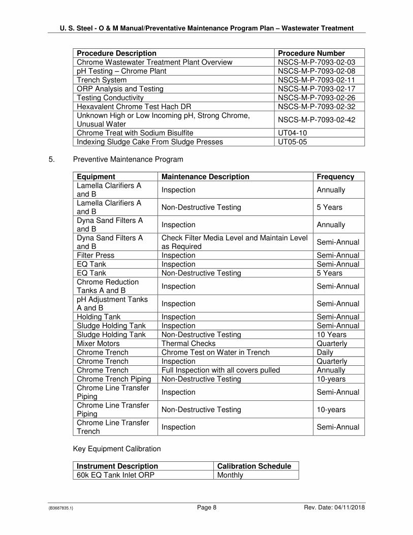
Procedure Description Procedure Number Chrome Wastewater Treatment Plant Overview NSCS-M-P-7093-02-03 pH Testing – Chrome Plant NSCS-M-P-7093-02-08 Trench System NSCS-M-P-7093-02-11 ORP Analysis and Testing NSCS-M-P-7093-02-17 Testing Conductivity NSCS-M-P-7093-02-26 Hexavalent Chrome Test Hach DR NSCS-M-P-7093-02-32 Unknown High or Low Incoming pH, Strong Chrome, Unusual Water
NSCS-M-P-7093-02-42
Chrome Treat with Sodium Bisulfite UT04-10 Indexing Sludge Cake From Sludge Presses UT05-05
5. Preventive Maintenance Program
Equipment Maintenance Description Frequency Lamella Clarifiers A and B
Inspection Annually
Lamella Clarifiers A and B
Non-Destructive Testing 5 Years
Dyna Sand Filters A and B
Inspection Annually
Dyna Sand Filters A and B
Check Filter Media Level and Maintain Level as Required
Semi-Annual
Filter Press Inspection Semi-Annual EQ Tank Inspection Semi-Annual EQ Tank Non-Destructive Testing 5 Years Chrome Reduction Tanks A and B
Inspection Semi-Annual
pH Adjustment Tanks A and B
Inspection Semi-Annual
Holding Tank Inspection Semi-Annual Sludge Holding Tank Inspection Semi-Annual Sludge Holding Tank Non-Destructive Testing 10 Years Mixer Motors Thermal Checks Quarterly Chrome Trench Chrome Test on Water in Trench Daily Chrome Trench Inspection Quarterly Chrome Trench Full Inspection with all covers pulled Annually Chrome Trench Piping Non-Destructive Testing 10-years Chrome Line Transfer Piping
Inspection Semi-Annual
Chrome Line Transfer Piping
Non-Destructive Testing 10-years
Chrome Line Transfer Trench
Inspection Semi-Annual
Key Equipment Calibration
Instrument Description Calibration Schedule 60k EQ Tank Inlet ORP Monthly
U. S. Steel - O & M Manual/Preventative Maintenance Program Plan – Wastewater Treatment
{B3687835.1} Page 9 Rev. Date: 04/11/2018
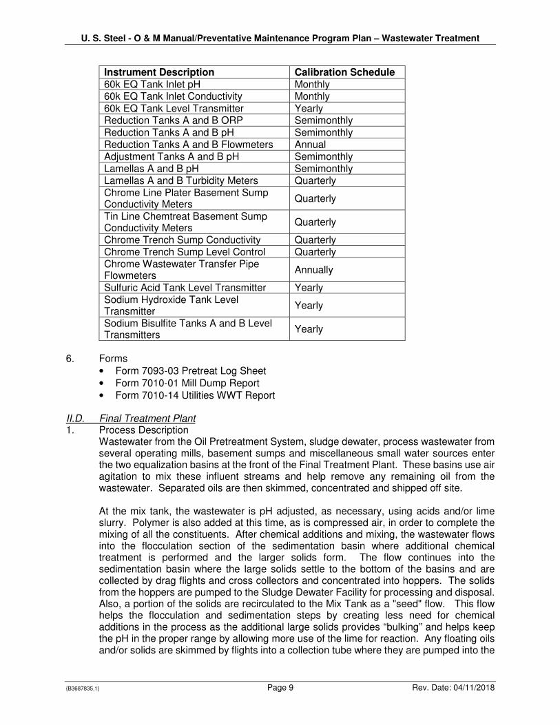
Instrument Description Calibration Schedule 60k EQ Tank Inlet pH Monthly 60k EQ Tank Inlet Conductivity Monthly 60k EQ Tank Level Transmitter Yearly Reduction Tanks A and B ORP Semimonthly Reduction Tanks A and B pH Semimonthly Reduction Tanks A and B Flowmeters Annual Adjustment Tanks A and B pH Semimonthly Lamellas A and B pH Semimonthly Lamellas A and B Turbidity Meters Quarterly Chrome Line Plater Basement Sump Conductivity Meters
Quarterly
Tin Line Chemtreat Basement Sump Conductivity Meters
Quarterly
Chrome Trench Sump Conductivity Quarterly Chrome Trench Sump Level Control Quarterly Chrome Wastewater Transfer Pipe Flowmeters
Annually
Sulfuric Acid Tank Level Transmitter Yearly Sodium Hydroxide Tank Level Transmitter
Yearly
Sodium Bisulfite Tanks A and B Level Transmitters
Yearly
6. Forms
• Form 7093-03 Pretreat Log Sheet
• Form 7010-01 Mill Dump Report
• Form 7010-14 Utilities WWT Report
II.D. Final Treatment Plant 1. Process Description
Wastewater from the Oil Pretreatment System, sludge dewater, process wastewater from several operating mills, basement sumps and miscellaneous small water sources enter the two equalization basins at the front of the Final Treatment Plant. These basins use air agitation to mix these influent streams and help remove any remaining oil from the wastewater. Separated oils are then skimmed, concentrated and shipped off site. At the mix tank, the wastewater is pH adjusted, as necessary, using acids and/or lime slurry. Polymer is also added at this time, as is compressed air, in order to complete the mixing of all the constituents. After chemical additions and mixing, the wastewater flows into the flocculation section of the sedimentation basin where additional chemical treatment is performed and the larger solids form. The flow continues into the sedimentation basin where the large solids settle to the bottom of the basins and are collected by drag flights and cross collectors and concentrated into hoppers. The solids from the hoppers are pumped to the Sludge Dewater Facility for processing and disposal. Also, a portion of the solids are recirculated to the Mix Tank as a "seed" flow. This flow helps the flocculation and sedimentation steps by creating less need for chemical additions in the process as the additional large solids provides “bulking” and helps keep the pH in the proper range by allowing more use of the lime for reaction. Any floating oils and/or solids are skimmed by flights into a collection tube where they are pumped into the
U. S. Steel - O & M Manual/Preventative Maintenance Program Plan – Wastewater Treatment
{B3687835.1} Page 10 Rev. Date: 04/11/2018
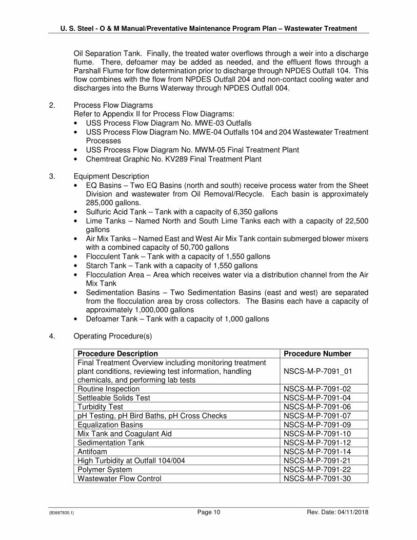
Oil Separation Tank. Finally, the treated water overflows through a weir into a discharge flume. There, defoamer may be added as needed, and the effluent flows through a Parshall Flume for flow determination prior to discharge through NPDES Outfall 104. This flow combines with the flow from NPDES Outfall 204 and non-contact cooling water and discharges into the Burns Waterway through NPDES Outfall 004.
2. Process Flow Diagrams Refer to Appendix II for Process Flow Diagrams:
• USS Process Flow Diagram No. MWE-03 Outfalls
• USS Process Flow Diagram No. MWE-04 Outfalls 104 and 204 Wastewater Treatment Processes
• USS Process Flow Diagram No. MWM-05 Final Treatment Plant
• Chemtreat Graphic No. KV289 Final Treatment Plant 3. Equipment Description
• EQ Basins – Two EQ Basins (north and south) receive process water from the Sheet Division and wastewater from Oil Removal/Recycle. Each basin is approximately 285,000 gallons.
• Sulfuric Acid Tank – Tank with a capacity of 6,350 gallons
• Lime Tanks – Named North and South Lime Tanks each with a capacity of 22,500 gallons
• Air Mix Tanks – Named East and West Air Mix Tank contain submerged blower mixers with a combined capacity of 50,700 gallons
• Flocculent Tank – Tank with a capacity of 1,550 gallons
• Starch Tank – Tank with a capacity of 1,550 gallons
• Flocculation Area – Area which receives water via a distribution channel from the Air Mix Tank
• Sedimentation Basins – Two Sedimentation Basins (east and west) are separated from the flocculation area by cross collectors. The Basins each have a capacity of approximately 1,000,000 gallons
• Defoamer Tank – Tank with a capacity of 1,000 gallons
4. Operating Procedure(s)
Procedure Description Procedure Number Final Treatment Overview including monitoring treatment plant conditions, reviewing test information, handling chemicals, and performing lab tests
NSCS-M-P-7091_01
Routine Inspection NSCS-M-P-7091-02 Settleable Solids Test NSCS-M-P-7091-04 Turbidity Test NSCS-M-P-7091-06 pH Testing, pH Bird Baths, pH Cross Checks NSCS-M-P-7091-07 Equalization Basins NSCS-M-P-7091-09 Mix Tank and Coagulant Aid NSCS-M-P-7091-10 Sedimentation Tank NSCS-M-P-7091-12 Antifoam NSCS-M-P-7091-14 High Turbidity at Outfall 104/004 NSCS-M-P-7091-21 Polymer System NSCS-M-P-7091-22 Wastewater Flow Control NSCS-M-P-7091-30
U. S. Steel - O & M Manual/Preventative Maintenance Program Plan – Wastewater Treatment
{B3687835.1} Page 11 Rev. Date: 04/11/2018
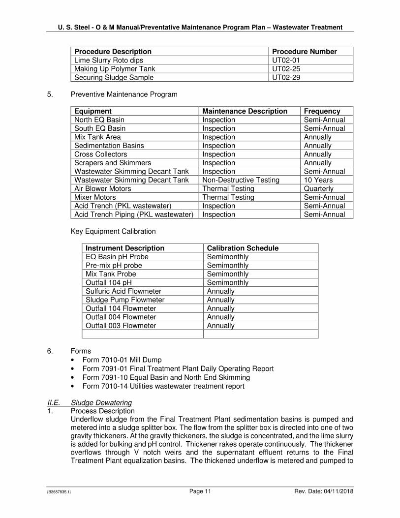
Procedure Description Procedure Number Lime Slurry Roto dips UT02-01 Making Up Polymer Tank UT02-25 Securing Sludge Sample UT02-29
5. Preventive Maintenance Program
Equipment Maintenance Description Frequency North EQ Basin Inspection Semi-Annual South EQ Basin Inspection Semi-Annual Mix Tank Area Inspection Annually Sedimentation Basins Inspection Annually Cross Collectors Inspection Annually Scrapers and Skimmers Inspection Annually Wastewater Skimming Decant Tank Inspection Semi-Annual Wastewater Skimming Decant Tank Non-Destructive Testing 10 Years Air Blower Motors Thermal Testing Quarterly Mixer Motors Thermal Testing Semi-Annual Acid Trench (PKL wastewater) Inspection Semi-Annual Acid Trench Piping (PKL wastewater) Inspection Semi-Annual
Key Equipment Calibration
Instrument Description Calibration Schedule EQ Basin pH Probe Semimonthly Pre-mix pH probe Semimonthly Mix Tank Probe Semimonthly Outfall 104 pH Semimonthly Sulfuric Acid Flowmeter Annually Sludge Pump Flowmeter Annually Outfall 104 Flowmeter Annually Outfall 004 Flowmeter Annually Outfall 003 Flowmeter Annually
6. Forms
• Form 7010-01 Mill Dump
• Form 7091-01 Final Treatment Plant Daily Operating Report
• Form 7091-10 Equal Basin and North End Skimming
• Form 7010-14 Utilities wastewater treatment report II.E. Sludge Dewatering 1. Process Description
Underflow sludge from the Final Treatment Plant sedimentation basins is pumped and metered into a sludge splitter box. The flow from the splitter box is directed into one of two gravity thickeners. At the gravity thickeners, the sludge is concentrated, and the lime slurry is added for bulking and pH control. Thickener rakes operate continuously. The thickener overflows through V notch weirs and the supernatant effluent returns to the Final Treatment Plant equalization basins. The thickened underflow is metered and pumped to
U. S. Steel - O & M Manual/Preventative Maintenance Program Plan – Wastewater Treatment
{B3687835.1} Page 12 Rev. Date: 04/11/2018
one of two filter presses. The filter press cycle of sludge followed by compressed air is then performed. The water pressed out returns to the Final Treatment EQ Basins and the dried sludge is dropped into a sludge box for disposal at the onsite landfill.
2. Process Flow Diagrams Refer to Appendix II for Process Flow Diagrams:
• USS Process Flow Diagram No. MWE-03 Outfalls
• USS Process Flow Diagram No. MWE-04 Outfalls 104 and 204 Wastewater treatment Processes
• USS Process Flow Diagram No. MWM-05 Final Treatment Area
• Chemtreat Graphic No. KV293 Sludge Dewatering Plant
3. Equipment Description
• Thickener Tanks – Two Tanks named East and West Thickener Tanks each with a capacity of 285,000 gallons.
• Lime Tank – Tank with a capacity of 104,000 dry pounds.
• Mix Tank – Tank equipped with a blower mixer to slake lime.
• Filter Presses – Two plate and frame filter presses named North and South Filter Press each equipped with 120 plates.
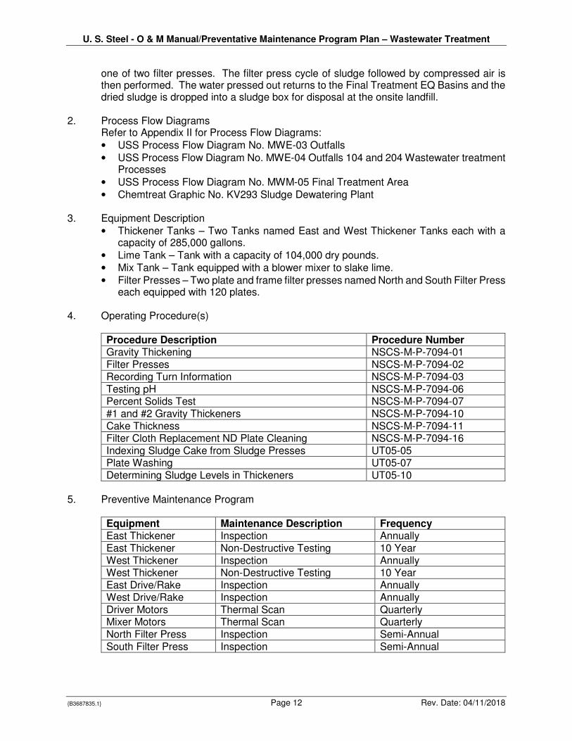
4. Operating Procedure(s)
Procedure Description Procedure Number Gravity Thickening NSCS-M-P-7094-01 Filter Presses NSCS-M-P-7094-02 Recording Turn Information NSCS-M-P-7094-03 Testing pH NSCS-M-P-7094-06 Percent Solids Test NSCS-M-P-7094-07 #1 and #2 Gravity Thickeners NSCS-M-P-7094-10 Cake Thickness NSCS-M-P-7094-11 Filter Cloth Replacement ND Plate Cleaning NSCS-M-P-7094-16 Indexing Sludge Cake from Sludge Presses UT05-05 Plate Washing UT05-07 Determining Sludge Levels in Thickeners UT05-10
5. Preventive Maintenance Program
Equipment Maintenance Description Frequency East Thickener Inspection Annually East Thickener Non-Destructive Testing 10 Year West Thickener Inspection Annually West Thickener Non-Destructive Testing 10 Year East Drive/Rake Inspection Annually West Drive/Rake Inspection Annually Driver Motors Thermal Scan Quarterly Mixer Motors Thermal Scan Quarterly North Filter Press Inspection Semi-Annual South Filter Press Inspection Semi-Annual
U. S. Steel - O & M Manual/Preventative Maintenance Program Plan – Wastewater Treatment
{B3687835.1} Page 13 Rev. Date: 04/11/2018
6. Forms
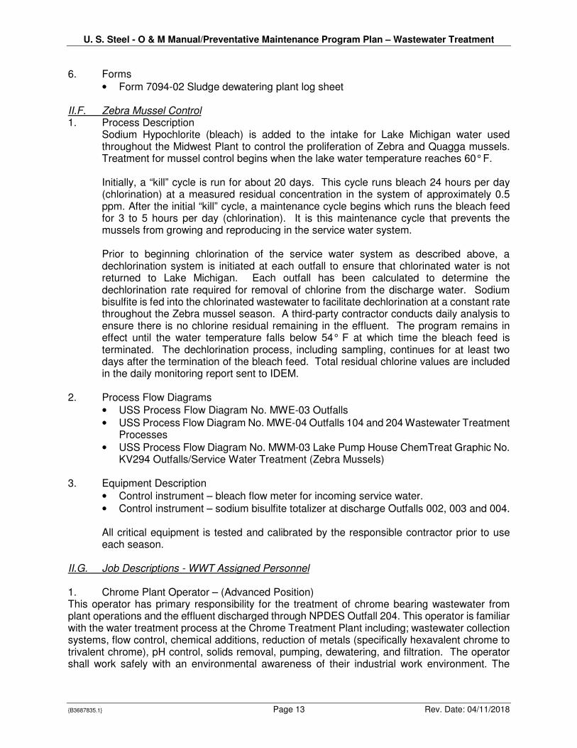
• Form 7094-02 Sludge dewatering plant log sheet II.F. Zebra Mussel Control 1. Process Description
Sodium Hypochlorite (bleach) is added to the intake for Lake Michigan water used throughout the Midwest Plant to control the proliferation of Zebra and Quagga mussels. Treatment for mussel control begins when the lake water temperature reaches 60° F. Initially, a “kill” cycle is run for about 20 days. This cycle runs bleach 24 hours per day (chlorination) at a measured residual concentration in the system of approximately 0.5 ppm. After the initial “kill” cycle, a maintenance cycle begins which runs the bleach feed for 3 to 5 hours per day (chlorination). It is this maintenance cycle that prevents the mussels from growing and reproducing in the service water system. Prior to beginning chlorination of the service water system as described above, a dechlorination system is initiated at each outfall to ensure that chlorinated water is not returned to Lake Michigan. Each outfall has been calculated to determine the dechlorination rate required for removal of chlorine from the discharge water. Sodium bisulfite is fed into the chlorinated wastewater to facilitate dechlorination at a constant rate throughout the Zebra mussel season. A third-party contractor conducts daily analysis to ensure there is no chlorine residual remaining in the effluent. The program remains in effect until the water temperature falls below 54° F at which time the bleach feed is terminated. The dechlorination process, including sampling, continues for at least two days after the termination of the bleach feed. Total residual chlorine values are included in the daily monitoring report sent to IDEM.
2. Process Flow Diagrams
• USS Process Flow Diagram No. MWE-03 Outfalls
• USS Process Flow Diagram No. MWE-04 Outfalls 104 and 204 Wastewater Treatment Processes
• USS Process Flow Diagram No. MWM-03 Lake Pump House ChemTreat Graphic No. KV294 Outfalls/Service Water Treatment (Zebra Mussels)
3. Equipment Description
• Control instrument – bleach flow meter for incoming service water.
• Control instrument – sodium bisulfite totalizer at discharge Outfalls 002, 003 and 004. All critical equipment is tested and calibrated by the responsible contractor prior to use each season.
II.G. Job Descriptions - WWT Assigned Personnel
1. Chrome Plant Operator – (Advanced Position) This operator has primary responsibility for the treatment of chrome bearing wastewater from plant operations and the effluent discharged through NPDES Outfall 204. This operator is familiar with the water treatment process at the Chrome Treatment Plant including; wastewater collection systems, flow control, chemical additions, reduction of metals (specifically hexavalent chrome to trivalent chrome), pH control, solids removal, pumping, dewatering, and filtration. The operator shall work safely with an environmental awareness of their industrial work environment. The
U. S. Steel - O & M Manual/Preventative Maintenance Program Plan – Wastewater Treatment
{B3687835.1} Page 14 Rev. Date: 04/11/2018
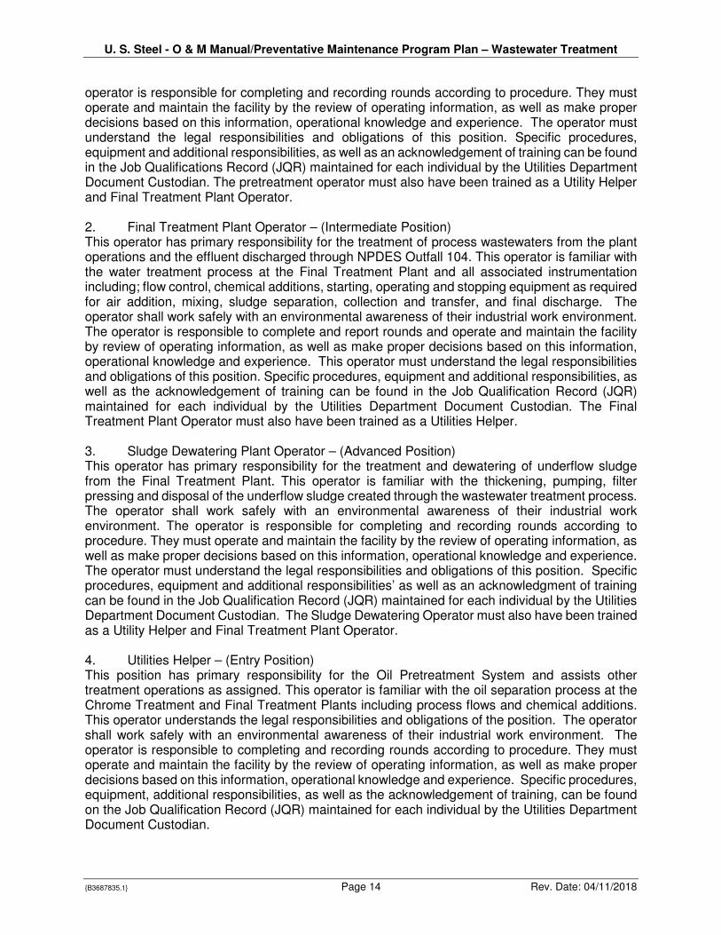
operator is responsible for completing and recording rounds according to procedure. They must operate and maintain the facility by the review of operating information, as well as make proper decisions based on this information, operational knowledge and experience. The operator must understand the legal responsibilities and obligations of this position. Specific procedures, equipment and additional responsibilities, as well as an acknowledgement of training can be found in the Job Qualifications Record (JQR) maintained for each individual by the Utilities Department Document Custodian. The pretreatment operator must also have been trained as a Utility Helper and Final Treatment Plant Operator. 2. Final Treatment Plant Operator – (Intermediate Position) This operator has primary responsibility for the treatment of process wastewaters from the plant operations and the effluent discharged through NPDES Outfall 104. This operator is familiar with the water treatment process at the Final Treatment Plant and all associated instrumentation including; flow control, chemical additions, starting, operating and stopping equipment as required for air addition, mixing, sludge separation, collection and transfer, and final discharge. The operator shall work safely with an environmental awareness of their industrial work environment. The operator is responsible to complete and report rounds and operate and maintain the facility by review of operating information, as well as make proper decisions based on this information, operational knowledge and experience. This operator must understand the legal responsibilities and obligations of this position. Specific procedures, equipment and additional responsibilities, as well as the acknowledgement of training can be found in the Job Qualification Record (JQR) maintained for each individual by the Utilities Department Document Custodian. The Final Treatment Plant Operator must also have been trained as a Utilities Helper.
3. Sludge Dewatering Plant Operator – (Advanced Position) This operator has primary responsibility for the treatment and dewatering of underflow sludge from the Final Treatment Plant. This operator is familiar with the thickening, pumping, filter pressing and disposal of the underflow sludge created through the wastewater treatment process. The operator shall work safely with an environmental awareness of their industrial work environment. The operator is responsible for completing and recording rounds according to procedure. They must operate and maintain the facility by the review of operating information, as well as make proper decisions based on this information, operational knowledge and experience. The operator must understand the legal responsibilities and obligations of this position. Specific procedures, equipment and additional responsibilities’ as well as an acknowledgment of training can be found in the Job Qualification Record (JQR) maintained for each individual by the Utilities Department Document Custodian. The Sludge Dewatering Operator must also have been trained as a Utility Helper and Final Treatment Plant Operator.
4. Utilities Helper – (Entry Position) This position has primary responsibility for the Oil Pretreatment System and assists other treatment operations as assigned. This operator is familiar with the oil separation process at the Chrome Treatment and Final Treatment Plants including process flows and chemical additions. This operator understands the legal responsibilities and obligations of the position. The operator shall work safely with an environmental awareness of their industrial work environment. The operator is responsible to completing and recording rounds according to procedure. They must operate and maintain the facility by the review of operating information, as well as make proper decisions based on this information, operational knowledge and experience. Specific procedures, equipment, additional responsibilities, as well as the acknowledgement of training, can be found on the Job Qualification Record (JQR) maintained for each individual by the Utilities Department Document Custodian.
U. S. Steel - O & M Manual/Preventative Maintenance Program Plan – Wastewater Treatment
{B3687835.1} Page 15 Rev. Date: 04/11/2018
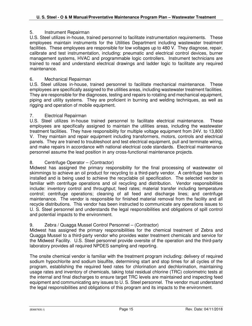
5. Instrument Repairman U.S. Steel utilizes in-house, trained personnel to facilitate instrumentation requirements. These employees maintain instruments for the Utilities Department including wastewater treatment facilities. These employees are responsible for low voltages up to 480 V. They diagnose, repair, calibrate and test instrumentation, including: pneumatic and electrical control devices, burner management systems, HVAC and programmable logic controllers. Instrument technicians are trained to read and understand electrical drawings and ladder logic to facilitate any required maintenance. 6. Mechanical Repairman U.S. Steel utilizes in-house, trained personnel to facilitate mechanical maintenance. These employees are specifically assigned to the utilities areas, including wastewater treatment facilities. They are responsible for the diagnoses, testing and repairs to rotating and mechanical equipment, piping and utility systems. They are proficient in burning and welding techniques, as well as rigging and operation of mobile equipment. 7. Electrical Repairman U.S. Steel utilizes in-house trained personnel to facilitate electrical maintenance. These employees are specifically assigned to maintain the utilities areas, including the wastewater treatment facilities. They have responsibility for multiple voltage equipment from 24V. to 13,800 V. They maintain and repair equipment including transformers, motors, controls and electrical panels. They are trained to troubleshoot and test electrical equipment, pull and terminate wiring, and make repairs in accordance with national electrical code standards. Electrical maintenance personnel assume the lead position in any cross-functional maintenance projects. 8. Centrifuge Operator – (Contractor) Midwest has assigned the primary responsibility for the final processing of wastewater oil skimmings to achieve an oil product for recycling to a third-party vendor. A centrifuge has been installed and is being used to achieve the recyclable oil specification. The selected vendor is familiar with centrifuge operations and oil recycling and distribution. Vendor responsibilities include: inventory control and throughput; feed rates; material transfer including temperature control; centrifuge operations; cleaning of all feed and discharge lines; and centrifuge maintenance. The vendor is responsible for finished material removal from the facility and all recycle distributions. This vendor has been instructed to communicate any operations issues to U. S. Steel personnel and understands the legal responsibilities and obligations of spill control and potential impacts to the environment.
9. Zebra / Quagga Mussel Control Personnel – (Contractor) Midwest has assigned the primary responsibilities for the chemical treatment of Zebra and Quagga Mussel to a third-party vendor who provides water treatment chemicals and service for the Midwest Facility. U.S. Steel personnel provide oversite of the operation and the third-party laboratory provides all required NPDES sampling and reporting.
The onsite chemical vendor is familiar with the treatment program including: delivery of required sodium hypochlorite and sodium bisulfite, determining start and stop times for all cycles of the program, establishing the required feed rates for chlorination and dechlorination, maintaining usage rates and inventory of chemicals, taking total residual chlorine (TRC) colorimetric tests at the internal and final discharges to ensure target TRC levels are maintained and inspecting feed equipment and communicating any issues to U. S. Steel personnel. The vendor must understand the legal responsibilities and obligations of this program and its impacts to the environment.
U. S. Steel - O & M Manual/Preventative Maintenance Program Plan – Wastewater Treatment
{B3687835.1} Page 16 Rev. Date: 04/11/2018
10. Chemical Supplier – (Contractor) This Chemical Supplier recommends water treatment products and is responsible for the ordering and delivery of wastewater treatment chemicals. They monitor chemical consumption and chemical tank levels, provide field testing as needed, and communicate and document treatment results. This vendor provides an account manager and trained, qualified personnel who have technical water treatment backgrounds and experience in steel operations, specifically at the Midwest Facility. Further, all vendor employees are trained in U. S. Steel requirements including immediate notification to U. S. Steel personnel of any issues, and maintaining an understanding of the legal responsibilities and obligations of spill control, operational issues and other potential impacts to the environment. 11. Sample Collection and Analysis – (Contractor) Midwest has assigned the primary responsibility for NPDES field services and analysis to a third-party vendor. This vendor provides all NPDES and groundwater sampling, operation and maintenance of required monitoring, sampling and flow monitoring equipment, sample transport to the laboratory per required procedures and all field analysis and report preparation as required by the NPDES permit. This vendor provides a project manager and trained, qualified personnel who are familiar with all sampling protocols for permits, orders and agency requirements associated with the Midwest Facility. Further, all vendor employees are trained in U. S. Steel requirements, including immediate notification to U. S. Steel personnel of any issues. The vendor employees must understand the legal responsibilities and obligations of spill control, operational issues and other potential impacts to the environment. III. Laboratory Requirements Midwest has assigned primary responsibility for analytical testing to a third-party laboratory. This testing includes analysis of all NPDES required testing, including internal locations, but does not include all process control testing. The contracted laboratory is directly associated with the field services group that collects the samples for analysis. U. S. Steel requires that the laboratory meet all the regulatory requirements. All analytical methods are approved by standard methods and undergo validation prior to their approval for use in the laboratory. The approval methods contain criteria for quality control and performance throughout all stages of analysis including sample preparation. The laboratory also performs internal audits of all systems by a quality assurance manager at each facility. Accreditation, certification and licensing bodies also perform audits to ensure laboratory conformance to all standards and regulations. The vendor has achieved accreditation from NELAC and various other industry programs including:
• EPA and OECD Good Laboratory Practices
• National Environmental Laboratory Accreditation Program
• U.S. Environmental Protection Agency
• North American Proficiency Testing Program
• National Voluntary Laboratory Accreditation Program The vendor has been instructed to immediately notify U. S. Steel personnel when any analysis exceeds NPDES permit or U. S. Steel internal limits. The vendor must understand the legal responsibilities of the permits, orders and impacts to the environment. IV. Recordkeeping Requirements

U. S. Steel - O & M Manual/Preventative Maintenance Program Plan – Wastewater Treatment
{B3687835.1} Page 17 Rev. Date: 04/11/2018
U. S. Steel complies with the recordkeeping requirements of this Operating and Maintenance Manual / Preventative Maintenance Program and the Permit by maintaining the appropriate data and records for a minimum of five years. V. Plan for Inspection, Cleaning and Maintenance of Outfall Channels The final outfalls are monitored for visual water quality on a daily basis. Maintenance inspections of the Outfall structures are conducted on an annual basis. Maintenance and cleaning activities are conducted, as necessary, based on these inspections. A third-party contractor is responsible for flow measurements at the Outfalls. They maintain and calibrate each flow meter per manufacturer recommendations. The flow meters are capable of accurate readings in varying flow conditions. VI. Preventive Maintenance Program Plan U. S. Steel conducts a Preventative Maintenance Program designed to help prevent breakdowns, reduce wear, improve efficiency and extend the life of its wastewater treatment infrastructure. Schedules for preventative maintenance inspections and testing are integrated into this Operating and Maintenance Manual for each wastewater treatment system at the Facility. The calibration schedules for key equipment and infrastructure for each treatment system are also provided above. U. S. Steel requires all contractors to maintain their own maintenance and preventative maintenance systems and procedures. VII. Review of O&M Plan and Preventative Maintenance Program Plan At least annually, U. S. Steel will review the O&M Manual, including the Preventative Maintenance Program, to determine whether modifications to the Manual are necessary for the proper operation and maintenance of the wastewater treatment process equipment. The results of the review will be documented and kept with the O&M Manual. The results will also be submitted along with the first semi-annual report due after completion of the annual O&M Manual review.

United States Steel O & M Manual – Waste Water Treatment
Appendix I.A. NPDES Permit Part I
Effluent Limits, Monitoring, & Conditions
Page 1 of 75 Permit No. IN0000337
STATE OF INDIANA
DEPARTMENT OF ENVIRONMENTAL MANAGEMENT
AUTHORIZATION TO DISCHARGE UNDER THE
NATIONAL POLLUTANT DISCHARGE ELIMINATION SYSTEM
In compliance with the provisions of the Federal Water Pollution Control Act, as amended, (33 U.S.C. 1251 et seq., the “Act”), and IDEM’s authority under IC13-15,
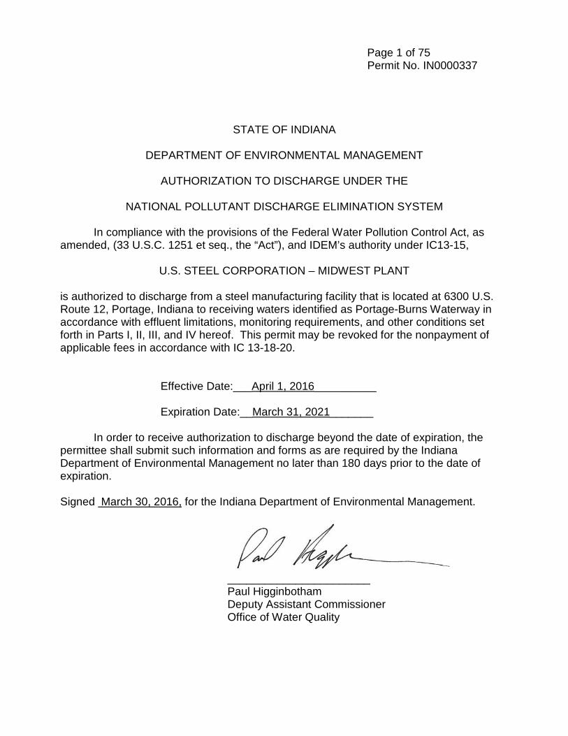
U.S. STEEL CORPORATION – MIDWEST PLANT is authorized to discharge from a steel manufacturing facility that is located at 6300 U.S. Route 12, Portage, Indiana to receiving waters identified as Portage-Burns Waterway in accordance with effluent limitations, monitoring requirements, and other conditions set forth in Parts I, II, III, and IV hereof. This permit may be revoked for the nonpayment of applicable fees in accordance with IC 13-18-20.
Effective Date:___April 1, 2016__________
Expiration Date:__March 31, 2021_______ In order to receive authorization to discharge beyond the date of expiration, the permittee shall submit such information and forms as are required by the Indiana Department of Environmental Management no later than 180 days prior to the date of expiration. Signed March 30, 2016, for the Indiana Department of Environmental Management.
_______________________ Paul Higginbotham
Deputy Assistant Commissioner Office of Water Quality
Page 2 of 75 Permit No. IN0000337
Table of Contents PART I
A. Effluent Limitations and Monitoring Requirements……….……………………………….…………………………..…….5
Outfall 002….…………………………………………………………………5 Outfall 003…………………………………………………………………….8 Outfall 004……………………………………………………………………11 Outfall 104 and 204……………………………………………………..…..13 Outfall 304……………………………………………………………..…….16
B. Narrative Water Quality Standards…………………………………………………19 C. Monitoring and Reporting………….……………………………………………….19
1. Representative Sampling……………………………………………..………….19 2. Discharge Monitoring Reports…………………………………………………...19 3. Definitions….……………………………………………………………………….20 4. Test Procedures……………………………………………………………………23 5. Recording of Results………………………………………………………………24 6. Additional Monitoring by Permittee …………………………………………..….24 7. Records Retention …………………………………………...…..……………….25
D. Storm Water Monitoring and Non-Numeric Conditions…………………………..25 E. Storm Water Pollution Prevention Plan…………………………………………….37 F. Chronic Biomonitoring Program Requirements……………………………………44 G. Pollution Minimization Program……………………………………………………..50 H. Toxic Pollutant Management Program……………………………………………..51 I. Reopening Clause…………………………………………………………………….52 J. Reporting Requirements for Solvents, Degreasing Agents, Rolling Oils, Water
Treatment Chemicals and Biocides………………………………………………….53 K. Schedule of Compliance………………………………………………………………53
PART II STANDARD CONDITIONS FOR NPDES PERMITS A. General Conditions
1. Duty to Comply………………………………………………………………...55 2. Duty to Mitigate………………………………………………………………...55 3. Duty to Reapply………………………………………………………………..55 4. Permit Transfer………………………………………………………………...56 5. Permit Actions……………………………………………………………….…56 6. Property Rights………………………………………………………………...57 7. Severability……………………………………………………………………..57 8. Oil and Hazardous Substance Liability……………………………………...58 9. State Laws……………………………………………………………………...58 10. Penalties for Violation of Permit Conditions………………………………..58 11. Penalties for Tampering of Falsification…………………………………….58 12. Toxic Pollutants………………………………………………………………...59 13. Wastewater treatment plant certified operators…………………………….59 14. Construction Permit…………………………………………………………….59 15. Inspection and Entry……………………………………………………………60 16. New or Increased Discharge of Pollutants into an OSRW…………………60
B. Management Requirements 1. Property Operations and Maintenance………………………………………61 2. Bypass of Treatment Facilities…………………………………………….61
Page 3 of 75 Permit No. IN0000337
3. Upset Conditions……………………………………………………………63 4. Removed Substances………………………………………………………64
C. Reporting Requirements……………………………………………………………..64 1. Planned Changes in Facility of Discharge………………………………..64 2. Monitoring and Reporting…………………………………………………..65 3. Twenty-Four Hour Reporting Requirements……………………………...65 4. Other Compliance/Noncompliance Reporting……………………………66 5. Other Information…………………………………………………………….67 6. Signatory Requirements…………………………………………………….67 7. Availability of Reports………………………………………………………..68 8. Penalties for Falsification of Reports………………………………………68 9. Changes in Discharge of Toxic Substances………………………………68
PART III OTHER REQUIREMENTS A. Thermal Effluent Requirements………………………………………………………70 B. Polychlorinated Biphenyl (PCB)………………………………………………………73
Part IV Cooling Water Intake Structure A. Best Technology Available (BTS) Determination……………………………….….74 B. Permit Requirements………………………………………………………………….74
Page 5 of 75 Permit No. IN0000337
A. EFFLUENT LIMITATIONS AND MONITORING REQUIREMENTS
1. The permittee is authorized to discharge from the outfall listed below in
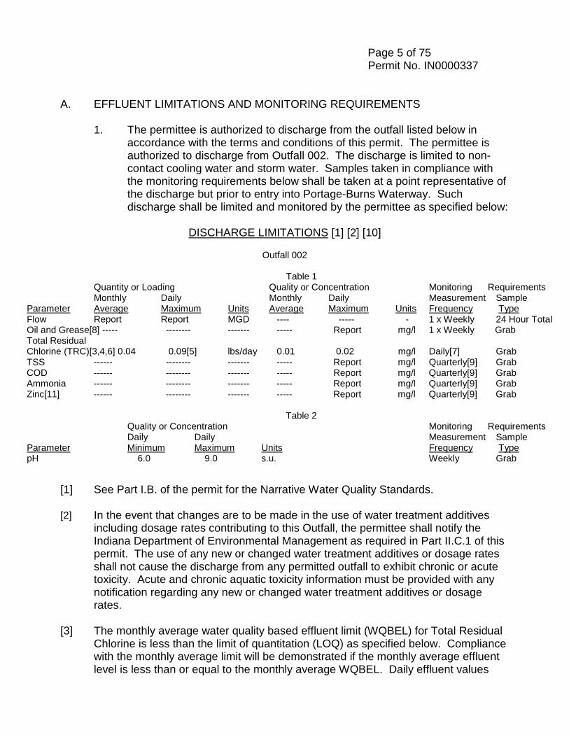
accordance with the terms and conditions of this permit. The permittee is authorized to discharge from Outfall 002. The discharge is limited to non-contact cooling water and storm water. Samples taken in compliance with the monitoring requirements below shall be taken at a point representative of the discharge but prior to entry into Portage-Burns Waterway. Such discharge shall be limited and monitored by the permittee as specified below:
DISCHARGE LIMITATIONS [1] [2] [10]
Outfall 002
Table 1
Quantity or Loading Quality or Concentration Monitoring Requirements Monthly Daily Monthly Daily Measurement Sample
Parameter Average Maximum Units Average Maximum Units Frequency Type Flow Report Report MGD ---- ----- - 1 x Weekly 24 Hour Total Oil and Grease[8] ----- -------- ------- ----- Report mg/l 1 x Weekly Grab Total Residual Chlorine (TRC)[3,4,6] 0.04 0.09[5] lbs/day 0.01 0.02 mg/l Daily[7] Grab TSS ------ -------- ------- ----- Report mg/l Quarterly[9] Grab COD ------ -------- ------- ----- Report mg/l Quarterly[9] Grab Ammonia ------ -------- ------- ----- Report mg/l Quarterly[9] Grab Zinc[11] ------ -------- ------- ----- Report mg/l Quarterly[9] Grab
Table 2 Quality or Concentration Monitoring Requirements
Daily Daily Measurement Sample Parameter Minimum Maximum Units Frequency Type pH 6.0 9.0 s.u. Weekly Grab
[1] See Part I.B. of the permit for the Narrative Water Quality Standards. [2] In the event that changes are to be made in the use of water treatment additives
including dosage rates contributing to this Outfall, the permittee shall notify the Indiana Department of Environmental Management as required in Part II.C.1 of this permit. The use of any new or changed water treatment additives or dosage rates shall not cause the discharge from any permitted outfall to exhibit chronic or acute toxicity. Acute and chronic aquatic toxicity information must be provided with any notification regarding any new or changed water treatment additives or dosage rates.
[3] The monthly average water quality based effluent limit (WQBEL) for Total Residual
Chlorine is less than the limit of quantitation (LOQ) as specified below. Compliance with the monthly average limit will be demonstrated if the monthly average effluent level is less than or equal to the monthly average WQBEL. Daily effluent values
Page 6 of 75 Permit No. IN0000337
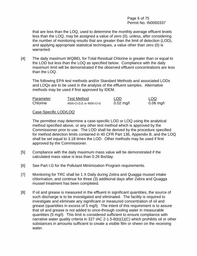
that are less than the LOQ, used to determine the monthly average effluent levels less than the LOQ, may be assigned a value of zero (0), unless, after considering the number of monitoring results that are greater than the limit of detection (LOD), and applying appropriate statistical techniques, a value other than zero (0) is warranted.
[4] The daily maximum WQBEL for Total Residual Chlorine is greater than or equal to
the LOD but less than the LOQ as specified below. Compliance with the daily maximum limit will be demonstrated if the observed effluent concentrations are less than the LOQ.
The following EPA test methods and/or Standard Methods and associated LODs
and LOQs are to be used in the analysis of the effluent samples. Alternative methods may be used if first approved by IDEM.
Parameter Test Method LOD LOQ Chlorine 4500-Cl-D,E or 4500-Cl-G 0.02 mg/l 0.06 mg/l Case-Specific LOD/LOQ The permittee may determine a case-specific LOD or LOQ using the analytical
method specified above, or any other test method which is approved by the Commissioner prior to use. The LOD shall be derived by the procedure specified for method detection limits contained in 40 CFR Part 136, Appendix B, and the LOQ shall be set equal to 3.18 times the LOD. Other methods may be used if first approved by the Commissioner.
[5] Compliance with the daily maximum mass value will be demonstrated if the
calculated mass value is less than 0.26 lbs/day. [6] See Part I.G for the Pollutant Minimization Program requirements. [7] Monitoring for TRC shall be 1 X Daily during Zebra and Quagga mussel intake
chlorination, and continue for three (3) additional days after Zebra and Quagga mussel treatment has been completed.
[8] If oil and grease is measured in the effluent in significant quantities, the source of
such discharge is to be investigated and eliminated. The facility is required to investigate and eliminate any significant or measured concentration of oil and grease (quantities in excess of 5 mg/l). The intent of this requirement is to assure that oil and grease is not added to once-through cooling water in measurable quantities (5 mg/l). This limit is considered sufficient to ensure compliance with narrative water quality criteria in 327 IAC 2-1.5-8(b)(1)(C) which prohibits oil or other substances in amounts sufficient to create a visible film or sheen on the receiving water.

Page 7 of 75 Permit No. IN0000337 [9] All samples shall be collected from the discharge resulting from a storm event that
is greater than 0.1 inches and at least 72 hours from the previously measurable (greater than 0.1 inch rainfall) storm event. For each sample taken, the permittee shall record the duration and total rainfall of the storm event, the number of hours between beginning of the storm measured and the end of the previous measurable rain event, and the outside temperature at the time of sampling.
A grab sample shall be taken during the first thirty (30) minutes of the discharge (or as soon thereafter as practicable).
[10] The Storm Water Monitoring and Non Numeric Effluent Limits and the Storm Water Pollution Prevention Plan (SWPPP) requirements can be found in Part I.D. and I.E. of this permit.
[11] The permittee shall measure and report the identified metal in total recoverable
form.
Page 8 of 75 Permit No. IN0000337
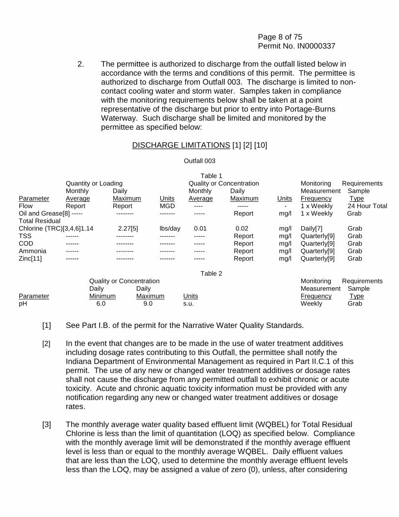
2. The permittee is authorized to discharge from the outfall listed below in accordance with the terms and conditions of this permit. The permittee is authorized to discharge from Outfall 003. The discharge is limited to non-contact cooling water and storm water. Samples taken in compliance with the monitoring requirements below shall be taken at a point representative of the discharge but prior to entry into Portage-Burns Waterway. Such discharge shall be limited and monitored by the permittee as specified below:
DISCHARGE LIMITATIONS [1] [2] [10]
Outfall 003
Table 1
Quantity or Loading Quality or Concentration Monitoring Requirements Monthly Daily Monthly Daily Measurement Sample
Parameter Average Maximum Units Average Maximum Units Frequency Type Flow Report Report MGD ---- ----- - 1 x Weekly 24 Hour Total Oil and Grease[8] ----- -------- ------- ----- Report mg/l 1 x Weekly Grab Total Residual Chlorine (TRC)[3,4,6]1.14 2.27[5] lbs/day 0.01 0.02 mg/l Daily[7] Grab TSS ------ -------- ------- ----- Report mg/l Quarterly[9] Grab COD ------ -------- ------- ----- Report mg/l Quarterly[9] Grab Ammonia ------ -------- ------- ----- Report mg/l Quarterly[9] Grab Zinc[11] ------ -------- ------- ----- Report mg/l Quarterly[9] Grab
Table 2 Quality or Concentration Monitoring Requirements
Daily Daily Measurement Sample Parameter Minimum Maximum Units Frequency Type pH 6.0 9.0 s.u. Weekly Grab
[1] See Part I.B. of the permit for the Narrative Water Quality Standards. [2] In the event that changes are to be made in the use of water treatment additives
including dosage rates contributing to this Outfall, the permittee shall notify the Indiana Department of Environmental Management as required in Part II.C.1 of this permit. The use of any new or changed water treatment additives or dosage rates shall not cause the discharge from any permitted outfall to exhibit chronic or acute toxicity. Acute and chronic aquatic toxicity information must be provided with any notification regarding any new or changed water treatment additives or dosage rates.
[3] The monthly average water quality based effluent limit (WQBEL) for Total Residual
Chlorine is less than the limit of quantitation (LOQ) as specified below. Compliance with the monthly average limit will be demonstrated if the monthly average effluent level is less than or equal to the monthly average WQBEL. Daily effluent values that are less than the LOQ, used to determine the monthly average effluent levels less than the LOQ, may be assigned a value of zero (0), unless, after considering
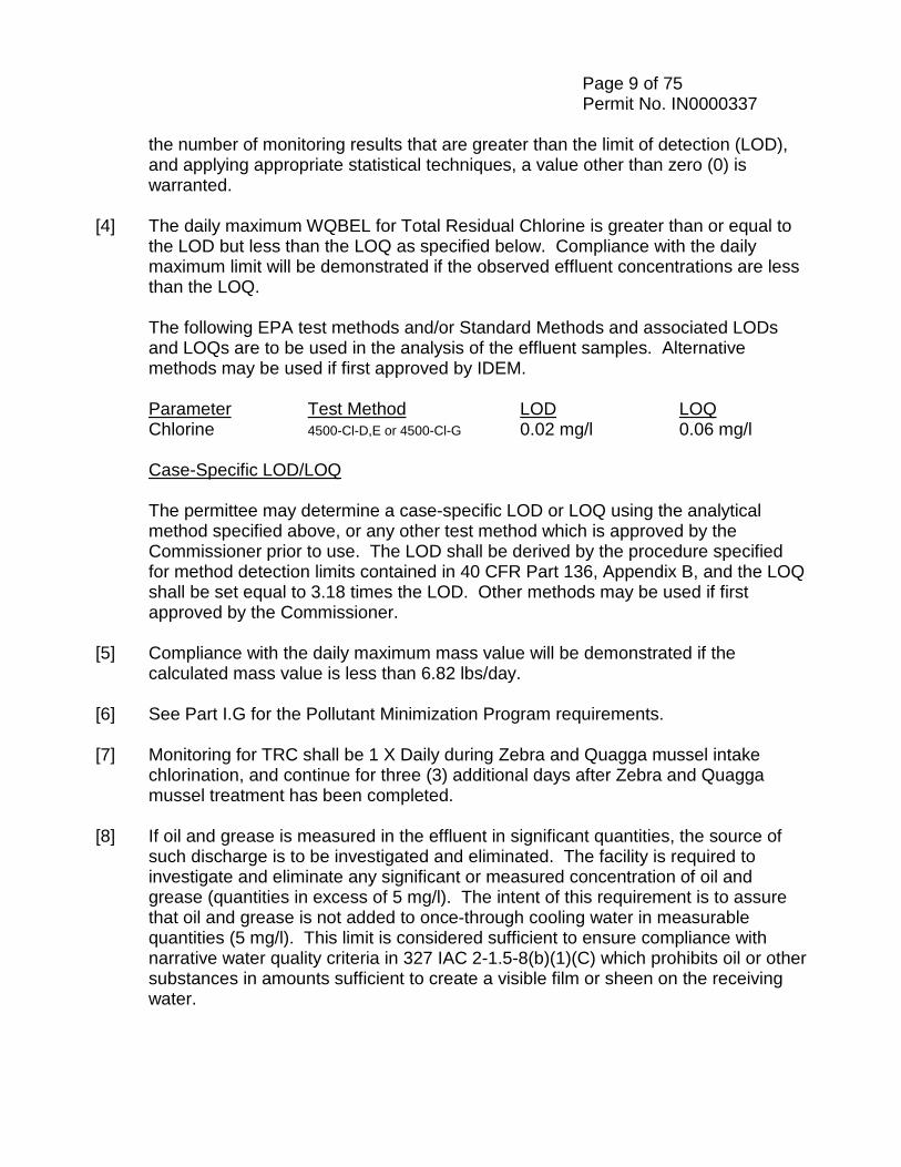
Page 9 of 75 Permit No. IN0000337
the number of monitoring results that are greater than the limit of detection (LOD), and applying appropriate statistical techniques, a value other than zero (0) is warranted.
[4] The daily maximum WQBEL for Total Residual Chlorine is greater than or equal to
the LOD but less than the LOQ as specified below. Compliance with the daily maximum limit will be demonstrated if the observed effluent concentrations are less than the LOQ.
The following EPA test methods and/or Standard Methods and associated LODs
and LOQs are to be used in the analysis of the effluent samples. Alternative methods may be used if first approved by IDEM.
Parameter Test Method LOD LOQ Chlorine 4500-Cl-D,E or 4500-Cl-G 0.02 mg/l 0.06 mg/l Case-Specific LOD/LOQ The permittee may determine a case-specific LOD or LOQ using the analytical
method specified above, or any other test method which is approved by the Commissioner prior to use. The LOD shall be derived by the procedure specified for method detection limits contained in 40 CFR Part 136, Appendix B, and the LOQ shall be set equal to 3.18 times the LOD. Other methods may be used if first approved by the Commissioner.
[5] Compliance with the daily maximum mass value will be demonstrated if the
calculated mass value is less than 6.82 lbs/day. [6] See Part I.G for the Pollutant Minimization Program requirements. [7] Monitoring for TRC shall be 1 X Daily during Zebra and Quagga mussel intake
chlorination, and continue for three (3) additional days after Zebra and Quagga mussel treatment has been completed.
[8] If oil and grease is measured in the effluent in significant quantities, the source of
such discharge is to be investigated and eliminated. The facility is required to investigate and eliminate any significant or measured concentration of oil and grease (quantities in excess of 5 mg/l). The intent of this requirement is to assure that oil and grease is not added to once-through cooling water in measurable quantities (5 mg/l). This limit is considered sufficient to ensure compliance with narrative water quality criteria in 327 IAC 2-1.5-8(b)(1)(C) which prohibits oil or other substances in amounts sufficient to create a visible film or sheen on the receiving water.
Page 10 of 75 Permit No. IN0000337 [9] All samples shall be collected from the discharge resulting from a storm event that
is greater than 0.1 inches and at least 72 hours from the previously measurable (greater than 0.1 inch rainfall) storm event. For each sample taken, the permittee shall record the duration and total rainfall of the storm event, the number of hours between beginning of the storm measured and the end of the previous measurable rain event, and the outside temperature at the time of sampling.
A grab sample shall be taken during the first thirty (30) minutes of the discharge (or as soon thereafter as practicable).
[10] The Storm Water Monitoring and Non Numeric Effluent Limits and the Storm
Water Pollution Prevention Plan (SWPPP) requirements can be found in Part I.D. and I.E. of this permit.
[11] The permittee shall measure and report the identified metal in total recoverable
form.
Page 11 of 75 Permit No. IN0000337
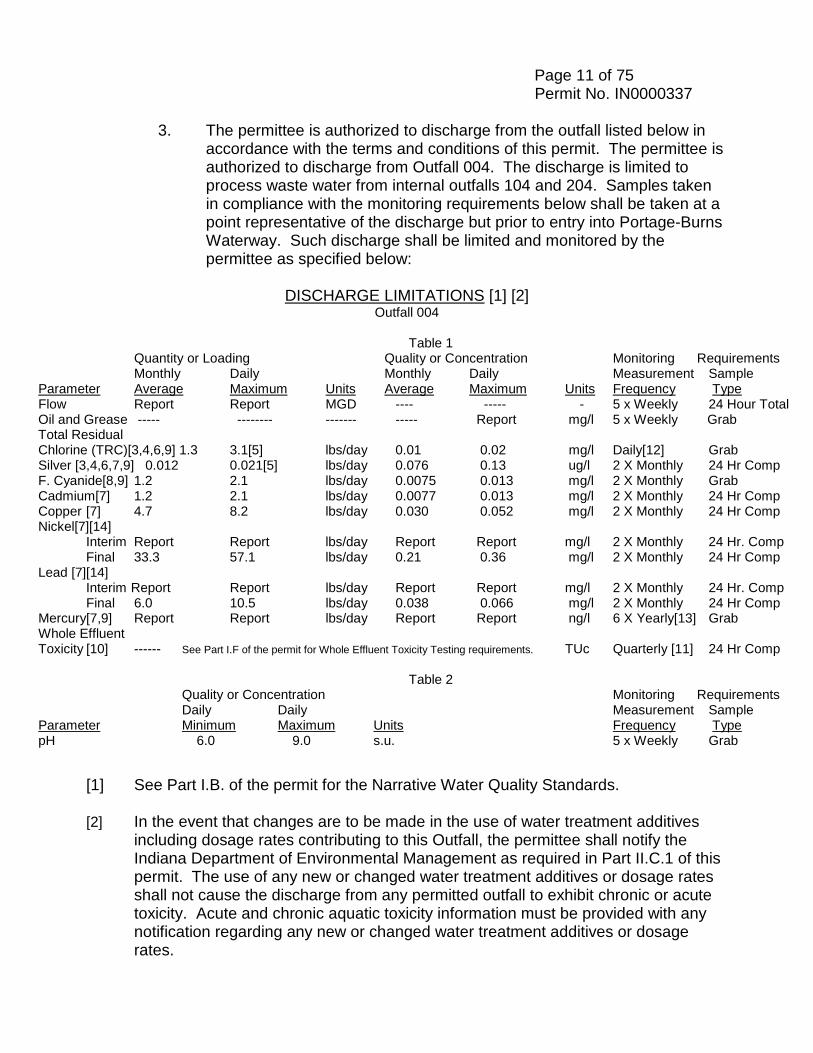
3. The permittee is authorized to discharge from the outfall listed below in accordance with the terms and conditions of this permit. The permittee is authorized to discharge from Outfall 004. The discharge is limited to process waste water from internal outfalls 104 and 204. Samples taken in compliance with the monitoring requirements below shall be taken at a point representative of the discharge but prior to entry into Portage-Burns Waterway. Such discharge shall be limited and monitored by the permittee as specified below:
DISCHARGE LIMITATIONS [1] [2]
Outfall 004
Table 1 Quantity or Loading Quality or Concentration Monitoring Requirements
Monthly Daily Monthly Daily Measurement Sample Parameter Average Maximum Units Average Maximum Units Frequency Type Flow Report Report MGD ---- ----- - 5 x Weekly 24 Hour Total Oil and Grease ----- -------- ------- ----- Report mg/l 5 x Weekly Grab Total Residual Chlorine (TRC)[3,4,6,9] 1.3 3.1[5] lbs/day 0.01 0.02 mg/l Daily[12] Grab Silver [3,4,6,7,9] 0.012 0.021[5] lbs/day 0.076 0.13 ug/l 2 X Monthly 24 Hr Comp F. Cyanide[8,9] 1.2 2.1 lbs/day 0.0075 0.013 mg/l 2 X Monthly Grab Cadmium[7] 1.2 2.1 lbs/day 0.0077 0.013 mg/l 2 X Monthly 24 Hr Comp Copper [7] 4.7 8.2 lbs/day 0.030 0.052 mg/l 2 X Monthly 24 Hr Comp Nickel[7][14]
Interim Report Report lbs/day Report Report mg/l 2 X Monthly 24 Hr. Comp Final 33.3 57.1 lbs/day 0.21 0.36 mg/l 2 X Monthly 24 Hr Comp
Lead [7][14] Interim Report Report lbs/day Report Report mg/l 2 X Monthly 24 Hr. Comp Final 6.0 10.5 lbs/day 0.038 0.066 mg/l 2 X Monthly 24 Hr Comp Mercury[7,9] Report Report lbs/day Report Report ng/l 6 X Yearly[13] Grab Whole Effluent Toxicity [10] ------ See Part I.F of the permit for Whole Effluent Toxicity Testing requirements. TUc Quarterly [11] 24 Hr Comp
Table 2 Quality or Concentration Monitoring Requirements
Daily Daily Measurement Sample Parameter Minimum Maximum Units Frequency Type pH 6.0 9.0 s.u. 5 x Weekly Grab
[1] See Part I.B. of the permit for the Narrative Water Quality Standards. [2] In the event that changes are to be made in the use of water treatment additives
including dosage rates contributing to this Outfall, the permittee shall notify the Indiana Department of Environmental Management as required in Part II.C.1 of this permit. The use of any new or changed water treatment additives or dosage rates shall not cause the discharge from any permitted outfall to exhibit chronic or acute toxicity. Acute and chronic aquatic toxicity information must be provided with any notification regarding any new or changed water treatment additives or dosage rates.
Page 12 of 75 Permit No. IN0000337 [3] The monthly average water quality based effluent limit (WQBEL) for Total Residual
Chlorine and Silver is less than the limit of quantitation (LOQ) as specified below (see footnote [9]). Compliance with the monthly average limit will be demonstrated if the monthly average effluent level is less than or equal to the monthly average WQBEL. Daily effluent values that are less than the LOQ, used to determine the monthly average effluent levels less than the LOQ, may be assigned a value of zero (0), unless, after considering the number of monitoring results that are greater than the limit of detection (LOD), and applying appropriate statistical techniques, a value other than zero (0) is warranted.
[4] The daily maximum WQBEL for Total Residual Chlorine and Silver is greater than
or equal to the LOD but less than the LOQ as specified below (see footnote [9]). Compliance with the daily maximum limit will be demonstrated if the observed effluent concentrations are less than the LOQ.
Case-Specific LOD/LOQ The permittee may determine a case-specific LOD or LOQ using the analytical
method specified above, or any other test method which is approved by the Commissioner prior to use. The LOD shall be derived by the procedure specified for method detection limits contained in 40 CFR Part 136, Appendix B, and the LOQ shall be set equal to 3.18 times the LOD. Other methods may be used if first approved by the Commissioner.
[5] Compliance with the daily maximum mass value will be demonstrated if the
calculated mass value is less than 9.51 lbs/day for Total Residual Chlorine and 0.1 lbs/day for Silver.
[6] See Part I.G for the Pollutant Minimization Program requirements. [7] The permittee shall measure and report the identified metal in total recoverable
form. [8] Sample preservation procedures and maximum allowable holding times for total
cyanide, or available (free) cyanide are prescribed in Table II of 40 CFR Part 136. Note the footnotes specific to cyanide. Preservation and holding time information in Table II takes precedence over information in specific methods or elsewhere.
[9] The following EPA test methods and/or Standard Methods and associated LODs
and LOQs are to be used in the analysis of the effluent samples. Alternative methods may be used if first approved by IDEM.
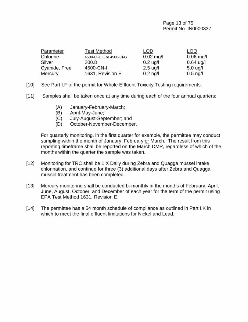
Page 13 of 75 Permit No. IN0000337
Parameter Test Method LOD LOQ Chlorine 4500-Cl-D,E or 4500-Cl-G 0.02 mg/l 0.06 mg/l Silver 200.8 0.2 ug/l 0.64 ug/l Cyanide, Free 4500-CN-I 2.5 ug/l 5.0 ug/l Mercury 1631, Revision E 0.2 ng/l 0.5 ng/l [10] See Part I.F of the permit for Whole Effluent Toxicity Testing requirements.
[11] Samples shall be taken once at any time during each of the four annual quarters: (A) January-February-March; (B) April-May-June; (C) July-August-September; and (D) October-November-December.
For quarterly monitoring, in the first quarter for example, the permittee may conduct sampling within the month of January, February or March. The result from this reporting timeframe shall be reported on the March DMR, regardless of which of the months within the quarter the sample was taken.
[12] Monitoring for TRC shall be 1 X Daily during Zebra and Quagga mussel intake
chlorination, and continue for three (3) additional days after Zebra and Quagga mussel treatment has been completed.
[13] Mercury monitoring shall be conducted bi-monthly in the months of February, April,
June, August, October, and December of each year for the term of the permit using EPA Test Method 1631, Revision E.
[14] The permittee has a 54 month schedule of compliance as outlined in Part I.K in
which to meet the final effluent limitations for Nickel and Lead.
Page 14 of 75 Permit No. IN0000337
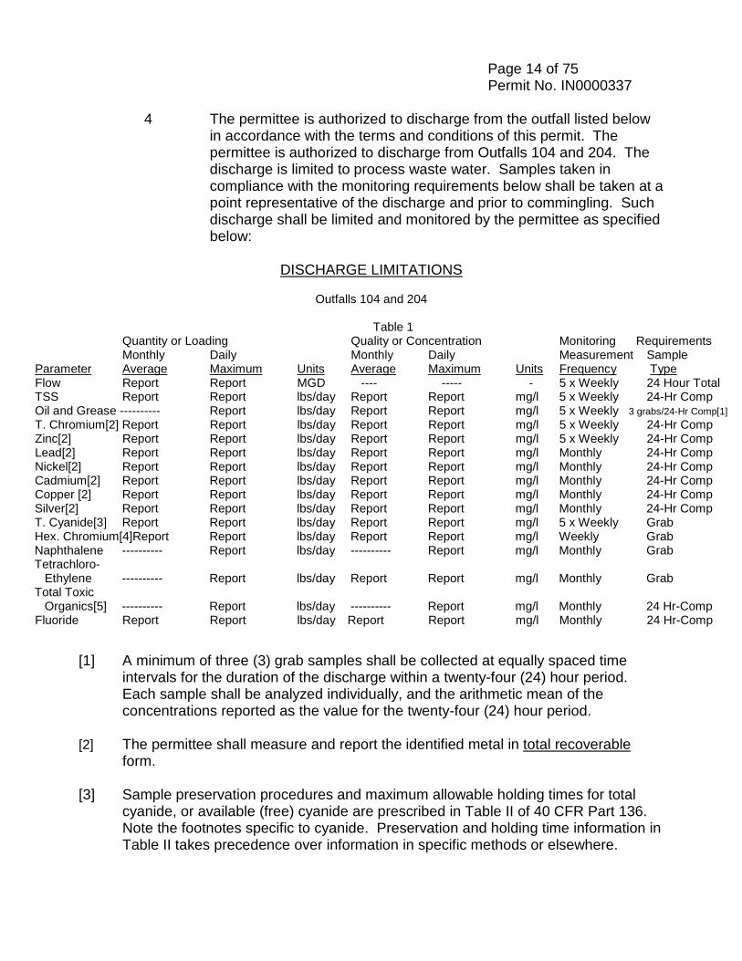
4 The permittee is authorized to discharge from the outfall listed below in accordance with the terms and conditions of this permit. The permittee is authorized to discharge from Outfalls 104 and 204. The discharge is limited to process waste water. Samples taken in compliance with the monitoring requirements below shall be taken at a point representative of the discharge and prior to commingling. Such discharge shall be limited and monitored by the permittee as specified below:
DISCHARGE LIMITATIONS
Outfalls 104 and 204
Table 1
Quantity or Loading Quality or Concentration Monitoring Requirements Monthly Daily Monthly Daily Measurement Sample
Parameter Average Maximum Units Average Maximum Units Frequency Type Flow Report Report MGD ---- ----- - 5 x Weekly 24 Hour Total TSS Report Report lbs/day Report Report mg/l 5 x Weekly 24-Hr Comp Oil and Grease ---------- Report lbs/day Report Report mg/l 5 x Weekly 3 grabs/24-Hr Comp[1] T. Chromium[2] Report Report lbs/day Report Report mg/l 5 x Weekly 24-Hr Comp Zinc[2] Report Report lbs/day Report Report mg/l 5 x Weekly 24-Hr Comp Lead[2] Report Report lbs/day Report Report mg/l Monthly 24-Hr Comp Nickel[2] Report Report lbs/day Report Report mg/l Monthly 24-Hr Comp Cadmium[2] Report Report lbs/day Report Report mg/l Monthly 24-Hr Comp Copper [2] Report Report lbs/day Report Report mg/l Monthly 24-Hr Comp Silver[2] Report Report lbs/day Report Report mg/l Monthly 24-Hr Comp T. Cyanide[3] Report Report lbs/day Report Report mg/l 5 x Weekly Grab Hex. Chromium[4]Report Report lbs/day Report Report mg/l Weekly Grab Naphthalene ---------- Report lbs/day ---------- Report mg/l Monthly Grab Tetrachloro- Ethylene ---------- Report lbs/day Report Report mg/l Monthly Grab Total Toxic Organics[5] ---------- Report lbs/day ---------- Report mg/l Monthly 24 Hr-Comp Fluoride Report Report lbs/day Report Report mg/l Monthly 24 Hr-Comp
[1] A minimum of three (3) grab samples shall be collected at equally spaced time intervals for the duration of the discharge within a twenty-four (24) hour period. Each sample shall be analyzed individually, and the arithmetic mean of the concentrations reported as the value for the twenty-four (24) hour period.
[2] The permittee shall measure and report the identified metal in total recoverable
form. [3] Sample preservation procedures and maximum allowable holding times for total
cyanide, or available (free) cyanide are prescribed in Table II of 40 CFR Part 136. Note the footnotes specific to cyanide. Preservation and holding time information in Table II takes precedence over information in specific methods or elsewhere.
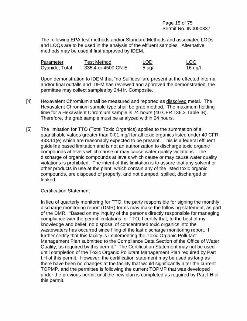
Page 15 of 75 Permit No. IN0000337
The following EPA test methods and/or Standard Methods and associated LODs and LOQs are to be used in the analysis of the effluent samples. Alternative methods may be used if first approved by IDEM.
Parameter Test Method LOD LOQ Cyanide, Total 335.4 or 4500 CN-E 5 ug/l 16 ug/l
Upon demonstration to IDEM that “no Sulfides” are present at the effected internal and/or final outfalls and IDEM has reviewed and approved the demonstration, the permittee may collect samples by 24-Hr. Composite.
[4] Hexavalent Chromium shall be measured and reported as dissolved metal. The Hexavalent Chromium sample type shall be grab method. The maximum holding
time for a Hexavalent Chromium sample is 24 hours (40 CFR 136.3 Table IB). Therefore, the grab sample must be analyzed within 24 hours.
[5] The limitation for TTO (Total Toxic Organics) applies to the summation of all
quantifiable values greater than 0.01 mg/l for all toxic organics listed under 40 CFR 433.11(e) which are reasonably expected to be present. This is a federal effluent guideline based limitation and is not an authorization to discharge toxic organic compounds at levels which cause or may cause water quality violations. The discharge of organic compounds at levels which cause or may cause water quality violations is prohibited. The intent of this limitation is to assure that any solvent or other products in use at the plant, which contain any of the listed toxic organic compounds, are disposed of properly, and not dumped, spilled, discharged or leaked.
Certification Statement
In lieu of quarterly monitoring for TTO, the party responsible for signing the monthly discharge monitoring report (DMR) forms may make the following statement, as part of the DMR: “Based on my inquiry of the persons directly responsible for managing compliance with the permit limitations for TTO, I certify that, to the best of my knowledge and belief, no disposal of concentrated toxic organics into the wastewaters has occurred since filing of the last discharge monitoring report. I further certify that this facility is implementing the Toxic Organic Pollutant Management Plan submitted to the Compliance Data Section of the Office of Water Quality, as required by this permit.” The Certification Statement may not be used until completion of the Toxic Organic Pollutant Management Plan required by Part I.H of this permit. However, the certification statement may be used as long as there have been no changes at the facility that would significantly alter the current TOPMP, and the permittee is following the current TOPMP that was developed under the previous permit until the new plan is completed as required by Part I.H of this permit.
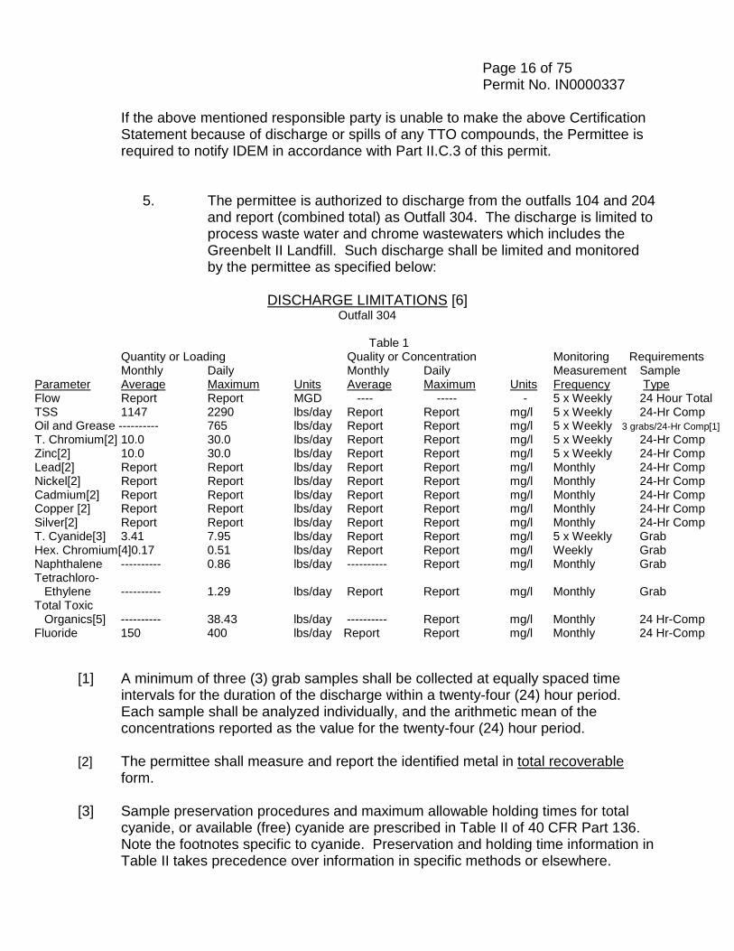
Page 16 of 75 Permit No. IN0000337
If the above mentioned responsible party is unable to make the above Certification Statement because of discharge or spills of any TTO compounds, the Permittee is required to notify IDEM in accordance with Part II.C.3 of this permit.
5. The permittee is authorized to discharge from the outfalls 104 and 204 and report (combined total) as Outfall 304. The discharge is limited to process waste water and chrome wastewaters which includes the Greenbelt II Landfill. Such discharge shall be limited and monitored by the permittee as specified below:
DISCHARGE LIMITATIONS [6]
Outfall 304
Table 1 Quantity or Loading Quality or Concentration Monitoring Requirements
Monthly Daily Monthly Daily Measurement Sample Parameter Average Maximum Units Average Maximum Units Frequency Type Flow Report Report MGD ---- ----- - 5 x Weekly 24 Hour Total TSS 1147 2290 lbs/day Report Report mg/l 5 x Weekly 24-Hr Comp Oil and Grease ---------- 765 lbs/day Report Report mg/l 5 x Weekly 3 grabs/24-Hr Comp[1] T. Chromium[2] 10.0 30.0 lbs/day Report Report mg/l 5 x Weekly 24-Hr Comp Zinc[2] 10.0 30.0 lbs/day Report Report mg/l 5 x Weekly 24-Hr Comp Lead[2] Report Report lbs/day Report Report mg/l Monthly 24-Hr Comp Nickel[2] Report Report lbs/day Report Report mg/l Monthly 24-Hr Comp Cadmium[2] Report Report lbs/day Report Report mg/l Monthly 24-Hr Comp Copper [2] Report Report lbs/day Report Report mg/l Monthly 24-Hr Comp Silver[2] Report Report lbs/day Report Report mg/l Monthly 24-Hr Comp T. Cyanide[3] 3.41 7.95 lbs/day Report Report mg/l 5 x Weekly Grab Hex. Chromium[4]0.17 0.51 lbs/day Report Report mg/l Weekly Grab Naphthalene ---------- 0.86 lbs/day ---------- Report mg/l Monthly Grab Tetrachloro- Ethylene ---------- 1.29 lbs/day Report Report mg/l Monthly Grab Total Toxic Organics[5] ---------- 38.43 lbs/day ---------- Report mg/l Monthly 24 Hr-Comp Fluoride 150 400 lbs/day Report Report mg/l Monthly 24 Hr-Comp
[1] A minimum of three (3) grab samples shall be collected at equally spaced time
intervals for the duration of the discharge within a twenty-four (24) hour period. Each sample shall be analyzed individually, and the arithmetic mean of the concentrations reported as the value for the twenty-four (24) hour period.
[2] The permittee shall measure and report the identified metal in total recoverable
form. [3] Sample preservation procedures and maximum allowable holding times for total
cyanide, or available (free) cyanide are prescribed in Table II of 40 CFR Part 136. Note the footnotes specific to cyanide. Preservation and holding time information in Table II takes precedence over information in specific methods or elsewhere.
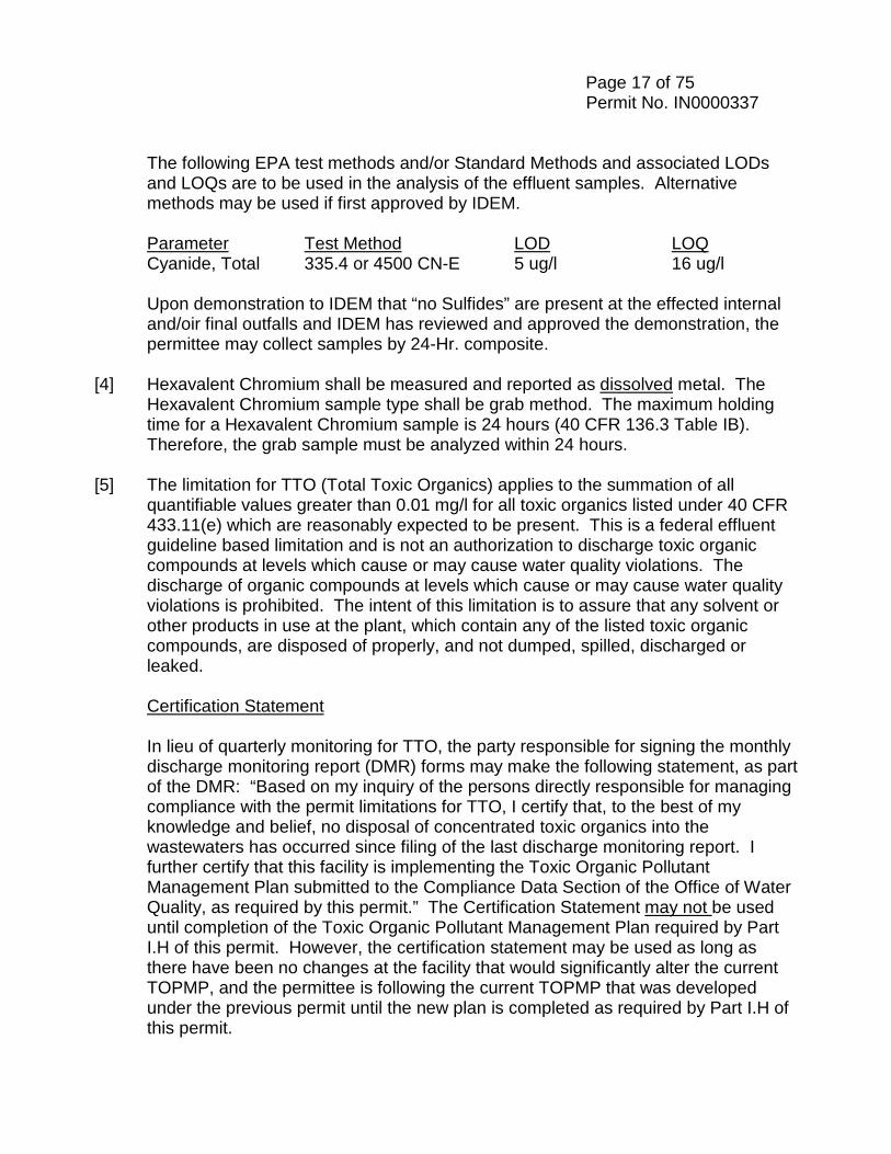
Page 17 of 75 Permit No. IN0000337
The following EPA test methods and/or Standard Methods and associated LODs and LOQs are to be used in the analysis of the effluent samples. Alternative methods may be used if first approved by IDEM.
Parameter Test Method LOD LOQ Cyanide, Total 335.4 or 4500 CN-E 5 ug/l 16 ug/l
Upon demonstration to IDEM that “no Sulfides” are present at the effected internal and/oir final outfalls and IDEM has reviewed and approved the demonstration, the permittee may collect samples by 24-Hr. composite.
[4] Hexavalent Chromium shall be measured and reported as dissolved metal. The Hexavalent Chromium sample type shall be grab method. The maximum holding
time for a Hexavalent Chromium sample is 24 hours (40 CFR 136.3 Table IB). Therefore, the grab sample must be analyzed within 24 hours.
[5] The limitation for TTO (Total Toxic Organics) applies to the summation of all
quantifiable values greater than 0.01 mg/l for all toxic organics listed under 40 CFR 433.11(e) which are reasonably expected to be present. This is a federal effluent guideline based limitation and is not an authorization to discharge toxic organic compounds at levels which cause or may cause water quality violations. The discharge of organic compounds at levels which cause or may cause water quality violations is prohibited. The intent of this limitation is to assure that any solvent or other products in use at the plant, which contain any of the listed toxic organic compounds, are disposed of properly, and not dumped, spilled, discharged or leaked.
Certification Statement
In lieu of quarterly monitoring for TTO, the party responsible for signing the monthly discharge monitoring report (DMR) forms may make the following statement, as part of the DMR: “Based on my inquiry of the persons directly responsible for managing compliance with the permit limitations for TTO, I certify that, to the best of my knowledge and belief, no disposal of concentrated toxic organics into the wastewaters has occurred since filing of the last discharge monitoring report. I further certify that this facility is implementing the Toxic Organic Pollutant Management Plan submitted to the Compliance Data Section of the Office of Water Quality, as required by this permit.” The Certification Statement may not be used until completion of the Toxic Organic Pollutant Management Plan required by Part I.H of this permit. However, the certification statement may be used as long as there have been no changes at the facility that would significantly alter the current TOPMP, and the permittee is following the current TOPMP that was developed under the previous permit until the new plan is completed as required by Part I.H of this permit.
Page 18 of 75 Permit No. IN0000337
If the above mentioned responsible party is unable to make the above Certification Statement because of discharge or spills of any TTO compounds, the Permittee is required to notify IDEM in accordance with Part II.C.3 of this permit.
[6] The reported mass for each parameter shall be calculated as a sum of mass in
lbs/day of both internal Outfalls 104 and 204 and reported as 304. Samples for discharges from Outfalls 104 and 204 shall be taken on the same day.
Page 19 of 75 Permit No. IN0000337 B. NARRATIVE WATER QUALITY STANDARDS
At all times the discharge from any and all point sources specified within this permit shall not cause receiving waters: 1. including the mixing zone, to contain substances, materials, floating debris,
oil, scum, or other pollutants:
a. that will settle to form putrescent or otherwise objectionable deposits; b. that are in amounts sufficient to be unsightly or deleterious; c. that produce color, visible oil sheen, odor, or other conditions in such
degree as to create a nuisance; d. which are in amounts sufficient to be acutely toxic to , or to otherwise
severely injure or kill aquatic life, other animals, plants, or humans; e. which are in concentrations or combinations that will cause or
contribute to the growth of aquatic plants or algae to such a degree as to create a nuisance, be unsightly, or otherwise impair the designated uses.
2. outside the mixing zone, to contain substances in concentrations which on
the basis of available scientific data are believed to be sufficient to injure, be chronically toxic to, or be carcinogenic, mutagenic, or teratogenic to humans, animals, aquatic life, or plants.
C. MONITORING AND REPORTING 1. Representative Sampling
Samples and measurements taken as required herein shall be representative of the volume and nature of the discharge.
2. Discharge Monitoring Reports
a. For parameters with monthly average water quality based effluent limitations (WQBELs) below the LOQ, daily effluent values that are less than the limit of quantitation (LOQ) may be assigned a value of zero (0).
b. For all other parameters for which the monthly average WQBEL is
equal to or greater than the LOQ, calculations that require averaging of measurements of daily values (both concentration and mass) shall use an arithmetic mean. When a daily discharge value is below the
Page 20 of 75 Permit No. IN0000337
LOQ, a value of zero (0) shall be used for that value in the calculation to determine the monthly average unless otherwise specified or approved by the Commissioner.
c. Effluent concentrations less than the LOD shall be reported on the Discharge Monitoring Report (DMR) forms as < (less than) the value of the LOD. For example, if a substance is not detected at a concentration of 0.1 µg/l, report the value as <0.1 µg/l.
d. Effluent concentrations greater than or equal to the LOD and less than the LOQ that are reported on a DMR shall be reported as the actual value and annotated on the DMR to indicate that the value is not quantifiable.
e. Mass discharge values which are calculated from concentrations reported as less than the value of the limit of detection shall be reported as less than the corresponding mass discharge value. f. Mass discharge values that are calculated from effluent concentrations greater than the limit of detection shall be reported as the calculated value.
The permittee shall submit federal and state discharge monitoring reports to the Indiana Department of Environmental Management containing results obtained during the previous month which shall be postmarked no later than the 28th day of the month following each completed monitoring period. The first report shall be submitted by the 28th day of the month following the month in which the permit becomes effective. All reports shall be either be mailed to IDEM, Office of Water Quality, Compliance Data Section, 100 North Senate Ave., Indianapolis, Indiana 46204-2251 or submitted electronically by using the NetDMR application, upon registration and approval receipt. Electronically submitted reports (using NetDMR) have the same deadline as mailed reports. After December 31, 2016, all reports shall be submitted using NetDMR and paper reports will no longer be accepted. The Regional Administrator may request the permittee to submit monitoring reports to the Environmental Protection Agency if it is deemed necessary to assure compliance with the permit.
3. Definitions
a. Monthly Average
(1) Mass Basis - The “monthly average” discharge means the total mass discharge during a calendar month divided by the number of days in the month that the production or commercial facility was discharging. Where less than daily samples is required by
Page 21 of 75 Permit No. IN0000337
this permit, the monthly average discharge shall be determined by the summation of the measured daily mass discharges divided by the number of days during the calendar month when the measurements were made.
(2) Concentration Basis - The “monthly average” concentration
means the arithmetic average of all daily determinations of concentration made during a calendar month. When grab samples are used, the daily determination of concentration shall be the arithmetic average (weighted by flow value) of all the samples collected during the calendar day.
b. “Daily Discharge”
(1) Mass Basis – The “daily discharge” means the total mass discharge by weight during any calendar day.
(2) Concentration Basis – The “daily discharge” means the
average concentration over the calendar day or any twenty-four (24) hour period that reasonably represents the calendar day for the purposes of sampling.
c. “Daily Maximum”
(1) Mass Basis – The “daily maximum” means the maximum daily discharge mass value for any calendar day.
(2) Concentration Basis – The “daily maximum” means the
maximum daily discharge value for any calendar day. (3) Temperature Basis – The “daily maximum” means the highest
temperature value measured for any calendar day. d. A 24-hour composite sample consists of at least 3 individual flow-
proportioned samples of wastewater, taken by the grab sample method or by an automatic sampler, which are taken at approximately equally spaced time intervals for the duration of the discharge within a 24-hour period and which are combined prior to analysis. A flow-proportioned composite sample may be obtained by:
(1) recording the discharge flow rate at the time each individual
sample is taken,
(2) adding together the discharge flow rates recorded from each individuals sampling time to formulate the “total flow” value,
Page 22 of 75 Permit No. IN0000337
(3) the discharge flow rate of each individual sampling time is divided by the total flow value to determine its percentage of the total flow value,
(4) then multiply the volume of the total composite sample by each
individual sample’s percentage to determine the volume of that individual sample which will be included in the total composite sample.
e. Concentration -The weight of any given material present in a unit
volume of liquid. Unless otherwise indicated in this permit, concentration values shall be expressed in milligrams per liter (mg/l).
f. The “Regional Administrator” is defined as the Region 5 Administrator,
U.S. EPA, located at 77 West Jackson Boulevard, Chicago, Illinois 60604.
g. The “Commissioner” is defined as the Commissioner of the Indiana
Department of Environmental Management, which is located at the following address: 100 North Senate Avenue, Indianapolis, Indiana 46204.
h. “Limit of Detection” or “LOD” means a measurement of the
concentration of a substance that can be measured and reported with ninety-nine percent (99%) confidence that the analyte concentration is greater than zero (0) for a particular analytical method and sample matrix. The LOD is equivalent to the method detection level or MDL.
i. “Limit of Quantitation” or “LOQ” means a measurement of the
concentration of a contaminant obtained by using a specified laboratory procedure calibrated at a specified concentration above the method detection level. It is considered the lowest concentration at which a particular contaminant can be quantitatively measured using a specified laboratory procedure for monitoring of the contaminant. This term is also sometimes called limit quantification or quantification level.
j. “Method Detection Level” or “MDL” means the minimum concentration
of an analyte (substance) that can be measured and reported with a ninety-nine percent (99%) confidence that the analyte concentration is greater than zero (0) as determined by procedure set forth in 40 CFR 136, Appendix B. The method detection level or MDL is equivalent to the LOD.
Page 23 of 75 Permit No. IN0000337
4. Test Procedures
The analytical and sampling methods used shall conform to the current version of 40 CFR 136. Multiple editions of Standard Methods for the Examination of Water and Wastewater are currently approved for most methods, however, 40 CFR Part 136 should be checked to ascertain if a particular method is approved for a particular analyte. The approved methods may be included in the texts listed below. However, different but equivalent methods are allowable if they receive the prior written approval of the Commissioner and the U.S. Environmental Protection Agency.
a. Standard Methods for the Examination of Water and Wastewater 18th, 19th, or 20th Editions, 1992, 1995, or 1998, American Public Health Association, Washington, D.C. 20005.
b. A.S.T.M. Standards, Parts 23, Water; Atmosphere Analysis 1972 American Society for Testing and Materials, Philadelphia, PA 19103.
c. Methods for Chemical Analysis of Water and Wastes June 1974, Revised, March 1983, Environmental Protection Agency,
Water Quality Office, Analytical Quality Control Laboratory, 1014 Broadway, Cincinnati, OH 45202.
d. The following analytical method and limits of detection and limits of
quanititation shall be used:
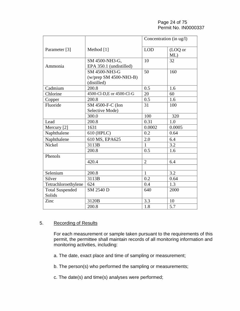
Page 24 of 75 Permit No. IN0000337
Parameter [3]
Method [1]
Concentration (in ug/l) LOD (LOQ or
ML) Ammonia
SM 4500-NH3-G, EPA 350.1 (undistilled)
10 32
SM 4500-NH3-G (w/prep SM 4500-NH3-B) (distilled)
50 160
Cadmium 200.8 0.5 1.6 Chlorine 4500-Cl-D,E or 4500-Cl-G 20 60 Copper 200.8 0.5 1.6 Fluoride SM 4500-F-C (Ion
Selective Mode) 31 100
300.0 100 320 Lead 200.8 0.31 1.0 Mercury [2] 1631 0.0002 0.0005 Naphthalene 610 (HPLC) 0.2 0.64 Naphthalene 610 MS, EPA625 2.0 6.4 Nickel 3113B 1 3.2
200.8 0.5 1.6 Phenols
420.4 2 6.4
Selenium 200.8 1 3.2
Silver 3113B 0.2 0.64 Tetrachloroethylene 624 0.4 1.3 Total Suspended Solids
SM 2540 D 640 2000
Zinc
3120B 3.3 10 200.8 1.8 5.7
5. Recording of Results
For each measurement or sample taken pursuant to the requirements of this permit, the permittee shall maintain records of all monitoring information and monitoring activities, including:
a. The date, exact place and time of sampling or measurement; b. The person(s) who performed the sampling or measurements; c. The date(s) and time(s) analyses were performed;
Page 25 of 75 Permit No. IN0000337
d. The person(s) who performed the analyses; e. The analytical techniques or methods used; and f. The results of such measurements and analyses.
6. Additional Monitoring by Permittee
If the permittee monitors any pollutant at the location(s) designated herein more frequently than required by this permit, using approved analytical methods as specified above, the results of this monitoring shall be included in the calculation and reporting of the values required in the monthly Discharge Monitoring Report (DMR) and Monthly Monitoring Report (MMR). Such increased frequency shall also be indicated. Other monitoring data not specifically required in this permit (such as internal process or internal waste stream data) which is collected by or for the permittee need not be submitted unless requested by the Commissioner.
7. Records Retention
All records and information resulting from the monitoring activities required by this permit, including all records of analyses performed and calibration and maintenance of instrumentation and recording from continuous monitoring instrumentation, shall be retained for a minimum of three (3) years. In cases where the original records are kept at another location, a copy of all such records shall be kept at the permitted facility. The three years shall be extended: a. automatically during the course of any unresolved litigation regarding
the discharge of pollutants by the permittee or regarding promulgated effluent guidelines applicable to the permittee; or
b. as requested by the Regional Administrator or the Indiana Department
of Environmental Management.
D. STORM WATER MONITORING AND NON-NUMERIC EFFLUENT LIMITS Within twelve (12) months of the effective date of this permit, the permittee shall
implement the non-numeric permit conditions in this Section of the permit for the entire site as it relates to storm water associated with industrial activity regardless which outfall the storm water is discharged from.
1. Control Measures and Effluent Limits
In the technology-based limits included in Part D.2-4., the term “minimize” means reduce and/or eliminate to the extent achievable using control measures (including best management practices) that are technologically
Page 26 of 75 Permit No. IN0000337
available and economically practicable and achievable in light of best industry practice.
2. Control Measures Select, design, install, and implement control measures (including best
management practices) to address the selection and design considerations in Part D.3 to meet the non-numeric effluent limits in Part D.4. The selection, design, installation, and implementation of these control measures must be in accordance with good engineering practices and manufacturer’s specifications. Any deviation from the manufacturer’s specifications shall be documented. If the control measures are not achieving their intended effect in minimizing pollutant discharges, the control measures must be modified as in accordance with the corrective action requirements in Part I.D.6. Regulated storm water discharges from the facility include storm water run-on that commingles with storm water discharges associated with industrial activity at the facility.
3. Control Measure Selection and Design Considerations
When selecting and designing control measures consider the following:
a. preventing storm water from coming into contact with polluting materials is generally more effective, and cost-effective, than trying to remove pollutants from storm water;
b. use of control measures in combination is more effective than use of
control measures in isolation for minimizing pollutants in storm water discharge;
c. assessing the type and quantity of pollutants, including their potential
to impact receiving water quality, is critical to designing effective control measures that will achieve the limits in this permit;
d. minimizing impervious areas at your facility and infiltrating runoff onsite (including bioretention cells, green roofs, and pervious
pavement, among other approaches), can reduce runoff and improve groundwater recharge and stream base flows in local streams, although care must be taken to avoid ground water contamination;
e. flow can be attenuated by use of open vegetated swales and natural
depressions; f. conservation and/or restoration of riparian buffers will help protect
streams from storm water runoff and improve water quality; and
Page 27 of 75 Permit No. IN0000337
g. use of treatment interceptors (e.g. swirl separators and sand filters) may be appropriate in some instances to minimize the discharge of pollutants.
4. Technology-Based Effluent Limits (BPT/BAT/BCT): Non-Numeric Effluent
Limits a. Minimize Exposure
Minimize the exposure of manufacturing, processing, and material storage areas (including loading and unloading, storage, disposal, cleaning, maintenance, and fueling operations) to rain, snow, snowmelt, and runoff. To the extent technologically available and economically practicable and achievable, either locate industrial materials and activities inside or protect them with storm resistant coverings in order to minimize exposure to rain, snow, snowmelt, and runoff (although significant enlargement of impervious surface area is not recommended). In minimizing exposure, pay particular attention to the following areas:
Note: Industrial materials do not need to be enclosed or covered if storm water runoff from affected areas will not be discharged to receiving waters.
b. Good Housekeeping
Keep clean all exposed areas that are potential sources of pollutants, using such measures as sweeping at regular intervals, store materials in appropriate containers, identify and control all on-site sources of dust to minimize stormwater contamination from the deposition of dust on areas exposed to precipitation, keep all dumpsters under cover or fit with a lid that must remain closed when not in use, and ensure that waste, garbage, and floatable debris are not discharged to receiving waters by keeping exposed areas free of such materials or by intercepting them before they are discharged. As part of the developed good housekeeping program, include a cleaning and maintenance program for all impervious areas of the facility where particulate matter, dust, or debris may accumulate, especially areas where material loading and unloading, storage, handling, and processing occur; and where practicable, the paving of areas where vehicle traffic or material storage occur but where vegetative or other stabilization methods are not practicable (institute a sweeping program in these areas too). For unstabilized areas where sweeping is not practicable, consider using storm water management devices such as sediment traps, vegetative buffer strips,
Page 28 of 75 Permit No. IN0000337
filter fabric fence, sediment filtering boom, gravel outlet protection, or other equivalent measures that effectively trap or remove sediment.
c. Maintenance Maintain all control measures which are used to achieve the effluent limits required by this permit in effective operating condition. Nonstructural control measures must also be diligently maintained (e.g., spill response supplies available, personnel appropriately trained). If control measures need to be replaced or repaired, make the necessary repairs or modifications as expeditiously as practicable.
d. Spill Prevention and Response Procedures
You must minimize the potential for leaks, spills and other releases that may be exposed to storm water and develop plans for effective response to such spills if or when they occur. At a minimum, you must implement: (1) Procedures for plainly labeling containers (e.g., "Used Oil",
"Spent Solvents", "Fertilizers and Pesticides", etc.) that could be susceptible to spillage or leakage to encourage proper handling and facilitate rapid response if spills or leaks occur;
(2) Preventive measures such as barriers between material
storage and traffic areas, secondary containment provisions, and procedures for material storage and handling;
(3) Procedures for expeditiously stopping, containing, and cleaning
up leaks, spills, and other releases. Employees who may cause, detect or respond to a spill or leak must be trained in these procedures and have necessary spill response equipment available. If possible, one of these individuals should be a member of your storm water pollution prevention team;
(4) Procedures for notification of appropriate facility personnel,
emergency response agencies, and regulatory agencies. State or local requirements may necessitate reporting spills or discharges to local emergency response, public health, or drinking water supply agencies. Contact information must be in locations that are readily accessible and available;
(5) A procedure for documenting all significant spills and leaks of
oil or toxic or hazardous pollutants that actually occurred at exposed areas, or that drained to a storm water conveyance.

Page 29 of 75 Permit No. IN0000337 e. Erosion and Sediment Controls
Through the use of structural and/or non-structural control measures stabilize, and contain runoff from, exposed areas to minimize onsite erosion and sedimentation, and the resulting discharge of pollutants. Among other actions to meet this limit, place flow velocity dissipation devices at discharge locations and within outfall channels where necessary to reduce erosion and/or settle out pollutants. In selecting, designing, installing, and implementing appropriate control measures for erosion and sediment control, you are encouraged to check out information from both the State and EPA websites. The following two websites are given as information sources: http://www.in.gov/idem/stormwater/2363.htm and http://water.epa.gov/polwaste/npdes/stormwater/Stormwater-Pollution-Prevention-Plans-for-Construction-Activities.cfm
f. Management of Runoff
Divert, infiltrate, reuse, contain or otherwise reduce storm water runoff, to minimize pollutants in the discharge.
g. Salt Storage Piles or Piles Containing Salt
Enclose or cover storage piles of salt, or piles containing salt, used for deicing or other commercial or industrial purposes, including maintenance of paved surfaces. You must implement appropriate measures (e.g., good housekeeping, diversions, containment) to minimize exposure resulting from adding to or removing materials from the pile. Piles do not need to be enclosed or covered if storm water runoff from the piles is not discharged.
h. Employee Training
Train all employees who work in areas where industrial material or activities are exposed to storm water, or who are responsible for implementing activities necessary to meet the conditions of this permit (e.g., inspectors, maintenance personnel), including all members of your Pollution Prevention Team. The following personnel must understand the requirements of Part I.D. and Part I.E. of this permit and their specific responsibilities with respect to those requirements: Personnel who are responsible for the design, installation, maintenance, and/or repair of controls (including pollution prevention measures); personnel responsible for the storage
Page 30 of 75 Permit No. IN0000337
and handling of chemicals and materials that could become contaminants in stormwater discharges; personnel who are responsible for conducting and documenting monitoring and inspections related to storm water; and personnel who are responsible for taking and documenting corrective actions as required in Part I.D.6.
Personnel must be trained in at least the following if related to the scope of their job duties (e.g., only personnel responsible for conducting inspections need to understand how to conduct inspections): an overview of what is in the SWPPP; spill response procedures, good housekeeping, maintenance requirements, and material management practices; the location of all controls on the site required by this permit, and how they are to be maintained; the proper procedures to follow with respect to the permit’s pollution prevention requirements; and when and how to conduct inspections, record applicable findings, and take corrective actions.
i. Non-Storm water Discharges
You must determine if any non-storm water discharges not authorized by an NPDES permit exist. Any non-storm water discharges discovered must either be eliminated or modified into this permit. The following non-storm water discharges are authorized and should be documented when they occur in accordance with Part I.E.2.c. of the permit:
Discharges from fire-fighting activities; Fire Hydrant flushings; Potable water, including water line flushings;
Uncontaminated condensate from air conditioners, coolers, and other compressors and from the outside storage of refrigerated gases or liquids; Irrigation drainage; Landscape watering provided all pesticides, herbicides, and fertilizer have been applied in accordance with the approved labeling; Pavement wash water where no detergents are used and no spills or leaks of toxic or hazardous material have occurred (unless all spilled material has been removed); Routine external building washdown that does not use detergents; Uncontaminated ground water or spring water; Foundation or footing drains where flows are not contaminated with process materials;
Page 31 of 75 Permit No. IN0000337
Incidental windblown mist from cooling towers that collects on rooftops or adjacent portions of the facility, but not intentional discharges from cooling towers (e.g., “piped cooling tower blowdown or drains);
Vehicle wash- waters where uncontaminated water without detergents or solvents is utilized; and
j. Dust Generation and Vehicle Tracking of Industrial
Materials
You must minimize generation of dust and off-site tracking of raw, final, or waste materials.
5. Annual Review
At least once every 12 months, you must submit an Annual Report which includes the following: the results or a summary of your past year’s routine facility inspection documentation and quarterly visual assessment documentation; information copied or summarized from the corrective action documentation required (if applicable). If corrective action is not yet completed at the time of submission of this Annual Report, you must describe the status of any outstanding corrective action(s); benchmark monitoring results, the rationale for why you believe that no further pollutant reductions are achievable (i.e., technologically available and economically practicable and achievable in light of best industry practices); and any incidents of noncompliance observed or, if there is no noncompliance, a certification signed by a responsible corporate officer, general partner or the proprietor, executive officer or ranking elected official, stating the facility is in compliance with this permit. You must also submit the report to the Industrial NPDES Permit Section on an annual basis.
6. Corrective Actions – Conditions Requiring Review
a. If any of the following conditions occur, you must review your SWPPP to determine if and where revisions may need to be made to eliminate the condition and prevent its reoccurrence:
(1) An unauthorized release or discharge (e.g., spill, leak, or
discharge of non-stormwater not authorized by this NPDES permit) occurs at your facility;
(2) Your control measures are not stringent enough for the
discharge to meet applicable water quality standards; (3) A required control measure was never installed, was installed
incorrectly, or is not being properly operated or maintained;
Page 32 of 75 Permit No. IN0000337
(4) Visual assessments indicate obvious signs of stormwater
pollution (e.g., color, odor, floating solids, settled solids, suspended solids, foam); or
(5) The average of four sampling results exceeds a benchmark. b. If the following condition occurs, you must review and revise
the selection, design, installation, and implementation of your control measures to determine if modifications are necessary to meet the effluent limits in this permit: construction or a change in design, operation, or maintenance at your facility that significantly changes the nature of pollutants discharged in storm water from your facility, or significantly increases the quantity of pollutants discharge.
7. Corrective Action Deadlines
If additional changes are necessary, a new or modified control must be installed and made operational, or a repair completed, before the next storm event if possible, and within 45 calendar days from the time of discovery by a member of the Stormwater Pollution Prevention Team. If it is infeasible to complete the installation or repair within 45 calendar days, , the reason(s) must be documented. A schedule for completing the work must also be identified, which must be done as soon as practicable after the 45-day timeframe but no longer than 90 days after discovery.
Where corrective actions result in changes to any of the controls or procedures documented in the SWPPP, the SWPPP must be modified accordingly within 14 calendar days of completing corrective action work. These time intervals are not grace periods, but are schedules considered reasonable for documenting your findings and for making repairs and improvements. They are included in this permit to ensure that the conditions prompting the need for these repairs and improvements are not allowed to persist indefinitely.
8. Corrective Action Report
The existence of any of the conditions listed in Part I.D.6 must be documented within 24 hours of a member of the Stormwater Pollution Prevention Team becoming aware of such condition. The following information must be included in the documentation:
Page 33 of 75 Permit No. IN0000337
(a) Identification and description of the condition triggering the need for corrective action review. For any spills or leaks, include the following information: a description of the incident including material, date/time, amount, location, and reason for spill, and any leaks, spills or other releases that resulted in discharges of pollutants to waters of U.S., through stormwater or otherwise;
(b) Date the condition was identified; and (c) A discussion of whether the triggering condition requires corrective
action. For any spills or leaks, include response actions, the date/time clean-up completed, notifications made, and staff involved. Also include any measures taken to prevent the reoccurrence of such releases.
You must also document the corrective actions taken that occurred as a result of the conditions listed in Part I.D.6. within 45 days from the time of discovery by a member of the Stormwater Pollution Prevention Team of any of those conditions. Provide the dates when each corrective action was initiated and completed (or is expected to be completed). If applicable, document why it is infeasible to complete necessary installations or repairs within the 45-day timeframe and document your schedule for installing the controls and making them operational as soon as practicable after the 45-day timeframe.
9. Inspections
(a) Routine Facility Inspections
During normal facility operating hours you must conduct inspections of areas of the facility covered by the requirements in this permit, including the following:
(1) Areas where industrial materials or activities are exposed to
stormwater; (2) Areas identified in the SWPPP and those that are potential
pollutant sources; (3) Areas where spills and leaks have occurred in the past 3 years. (4) Discharge points; and (5) Control measures used to comply with the effluent limits
contained in this permit.
Inspections must be conducted at least quarterly (i.e., once each calendar quarter), or in some instances more frequently (e.g., monthly), as appropriate. Increased frequency may be appropriate for some types of equipment, processes and stormwater control
Page 34 of 75 Permit No. IN0000337
measures, or areas of the facility with significant activities and materials exposed to stormwater. At least one of your routine inspections must be conducted during a period when a stormwater discharge is occurring.
Inspections must be performed by qualified personnel (as defined in Appendix A) with at least one member of your stormwater pollution prevention team participating. Inspectors must consider the results of visual and analytical monitoring (if any) for the past year when planning and conducting inspections.
During the inspection you must examine or look out for the following:
(6) Industrial materials, residue or trash that may have or could
come into contact with stormwater; (7) Leaks or spills from industrial equipment, drums, tanks and
other containers; (8) Offsite tracking of industrial or waste materials, or sediment
where vehicles enter or exit the site; (9) Tracking or blowing of raw, final or waste materials from areas
of no exposure to exposed areas; and (10) Control measures needing replacement, maintenance or repair.
As part of conducting your routine facility inspections at least quarterly, address all potential sources of pollutants, including (if applicable) air pollution control equipment. Also inspect all process and material handling equipment (e.g., conveyors, cranes, and vehicles) for leaks, drips, or the potential loss of material; and material storage areas (e.g., piles, bins, or hoppers for storing coke, coal, scrap, or slag, as well as chemicals stored in tanks and drums) for signs of material losses due to wind or stormwater runoff.
During an inspection occurring during a stormwater discharge, control measures implemented to comply with effluent limits must be observed to ensure they are functioning correctly. Discharge outfalls must also be observed during this inspection. If such discharge locations are inaccessible, nearby downstream locations must be inspected.
(b) Routine Facility Inspection Documentation
The findings of facility inspections must be documented and the report maintained with your SWPPP. Findings must be summarized in the
Page 35 of 75 Permit No. IN0000337
annual report. Document all findings, including but not limited to, the following information:
(1) The inspection date and time; (2) The name(s) and signature(s) of the inspector(s); (3) Weather information; (4) All observations relating to the implementation of control
measures at the facility, including: (a) A description of any discharges occurring at the time of
the inspection; (b) Any previously unidentified discharges and/or pollutants
from the site; (c) Any evidence of, or the potential for, pollutants entering
the drainage system; (d) Observations regarding the physical condition of and
around all outfalls including any flow dissipation devices, and evidence of pollutants in discharges and/or the receiving water;
(e) Any control measures needing maintenance, repairs, or replacement;
(5) Any additional control measures needed to comply with the permit requirements; and
(6) Any incidents of noncompliance observed.
Any corrective action required as a result of a routine facility inspection must be performed consistent with Part I.D.6. of this permit.
If the discharge was visual assessed, as required in Part I.D.9.c., during the facility inspection, you may include the results of the assessment with the report required in Part I.D.9.a., as long as all components of both types of inspections are included in the report.
(c) Quarterly Visual Assessment Procedures
Once each quarter for the entire permit term, you must collect a stormwater sample from each outfall and conduct a visual assessment of each of these samples. These samples are not required to be collected consistent with 40 CFR Part 136 procedures but should be collected in such a manner that the samples are representative of the stormwater discharge. Guidance on monitoring is available at: http://water.epa.gov/polwaste/npdes/stormwater/EPA-Multi-Sector-General-Permit-MSGP.cfm
Page 36 of 75 Permit No. IN0000337
The visual assessment must be made:
(1) Of a sample in a clean, clear glass, or plastic container, and examined in a well-lit area;
(2) On samples collected within the first 30 minutes of an actual discharge from a storm event. If it is not possible to collect the sample within the first 30 minutes of discharge, the sample must be collected as soon as practicable after the first 30 minutes and you must document why it was not possible to take samples within the first 30 minutes. In the case of snowmelt, samples must be taken during a period with a measurable discharge from your site; and
(3) For storm events, on discharges that occur at least 72 hours (3 days) from the previous discharge. The 72-hour (3-day) storm interval does not apply if you document that less than a 72-hour (3-day) interval is representative for local storm events during the sampling period.
You must visually inspect or observe the sample for the following water quality characteristics:
(4) Color; (5) Odor; (6) Clarity (diminished); (7) Floating solids; (8) Settled solids; (9) Suspended solids; (10) Foam;
(11) Oil sheen; and (12) Other obvious indicators of stormwater pollution.
Whenever the visual assessment shows stormwater discharges are not in compliance with narrative water quality criteria, initiate the corrective action procedures in Part I.D.6.
(d) Quarterly Visual Assessment Documentation
Results of visual assessments must be documented and the documentation maintained onsite with the SWPPP. Documentation of the visual assessment must include, but is not be limited to:
(1) Sample location(s); (2) Sample collection date and time, and visual assessment date
and time for each sample; (3) Personnel collecting the sample and performing visual
assessment, and their signatures;
Page 37 of 75 Permit No. IN0000337
(4) Nature of the discharge (i.e., runoff or snowmelt); (5) Results of observations of the stormwater discharge; (6) Probable sources of any observed stormwater contamination;
and (7) If applicable, why it was not possible to take samples within the
first 30 minutes.
Any corrective action required as a result of a quarterly visual assessment must be performed consistent with Part I.D.6. of this permit.
(e) Exceptions to Quarterly Visual Assessments
(1) Adverse Weather Conditions: When adverse weather
conditions prevent the collection of samples during the quarter, you must take a substitute sample during the next qualifying storm event. Documentation of the rationale for no visual assessment for the quarter must be included with your SWPPP records. Adverse conditions are those that are dangerous or create inaccessibility for personnel, such as local flooding, high winds, or electrical storms, or situations that otherwise make sampling impractical, such as extended frozen conditions.
(2) Snow: In areas subject to snow, if possible, at least one
quarterly visual assessment must capture snowmelt discharge, taking into account the exception described above for climates with irregular stormwater runoff.
E. STORM WATER POLLUTION PREVENTION PLAN 1. Development of Plan
Within 12 months from the effective date of this permit, the permittee is required to review and update the current Storm Water Pollution Prevention Plan (SWPPP) for the permitted facility. The SWPPP does not contain effluent limitations. The SWPPP is intended to document the selection, design, and installation of control measures. As distinct from the SWPPP, the additional documentation requirements are intended to document the implementation (including inspection, maintenance, monitoring, and corrective action) of the permit requirements. The plan shall at a minimum include the following: a. Identify potential sources of pollution, which may reasonably be
expected to affect the quality of storm water discharges associated with industrial activity from the facility. Storm water associated with industrial activity (defined in 40 CFR 122.26(b)(14)) includes, but is
Page 38 of 75 Permit No. IN0000337
not limited to, the discharge from any conveyance which is used for collecting and conveying storm water and which is directly related to manufacturing, processing or materials storage areas at an industrial plant;
b. Describe practices and measure to be used in reducing the potential
for pollutants to be exposed to storm water; and
c. Assure compliance with the terms and conditions of this permit.
2. Contents The plan shall include, at a minimum, the following items:
a. Pollution Prevention Team – The SWWPPP must identify the staff
members (by name or title) that comprise the facility’s stormwater pollution prevention team as well as their individual responsibilities. The stormwater pollution prevention team is responsible for overseeing development of the SWPPP, any later modifications to it, and for compliance with permit Parts I.D. and I.E. of this permit. Each member of the stormwater pollution prevention team must have ready access to either an electronic or paper copy of applicable portions of this permit, the most updated copy of the SWPPP, other relevant documents or information that must be kept with the SWPPP.
b. Site Description – As a minimum, the plan shall contain the following: (1) Activities at the Facility. Provide a description of the nature of
the industrial activities at your facility.
(2) General location map. Provide a general location map (e.g., U.S. Geological Survey (USGS) quadrangle map) with enough detail to identify the location of your facility and all receiving waters for your stormwater discharges.
(3) Site map. Provide a map showing:
(A) Boundaries of the property and the size of the property
in acres; (B) Location and extent of significant structures and
impervious surfaces; (C) Directions of stormwater flow (use arrows); (D) Locations of all stormwater control measures; (E) Locations of all receiving waters, including wetlands, in
the immediate vicinity of your facility. Indicate which
Page 39 of 75 Permit No. IN0000337
waterbodies are listed as impaired and which are identified by the State of Indiana or EPA as Tier 2 or Tier 2.5 waters;
(F) Locations of all stormwater conveyances including ditches, pipes, and swales;
(G) Locations of potential pollutant sources identified; (H) Locations where significant spills or leaks identified have
occurred; (I) Locations of all stormwater monitoring points; (J) Locations of stormwater inlets and outfalls, with a unique
identification code for each outfall (e.g., Outfall No. 1, No. 2), indicating if you are treating one or more outfalls as “substantially identical”, and an approximate outline of the areas draining to each outfall;
(K) If applicable, municipal separate storm sewer systems and where your stormwater discharges to them;
(L) Areas of federally-listed critical habitat for endangered or threatened species, if applicable.
(M) Locations of the following activities where such activities are exposed to precipitation: o fueling stations; i. vehicle and equipment maintenance and/or
cleaning areas; ii. loading/unloading areas; iii. locations used for the treatment, storage, or
disposal of wastes; iv. liquid storage tanks; v. processing and storage areas; vi. immediate access roads and rail lines used or
traveled by carriers of raw materials, manufactured products, waste material, or by-products used or created by the facility;
vii. transfer areas for substances in bulk; and viii. machinery
(N) Locations and sources of run-on to your site from
adjacent property that contains significant quantities of pollutants.
(O) Identify in the SWPPP where any of the following activities may be exposed to precipitation or surface runoff: storage or disposal of wastes such as spent solvents and baths, sand, slag and dross; liquid storage tanks and drums; processing areas including pollution control equipment (e.g., baghouses); and storage areas of raw material such as coal, coke, scrap, sand, fluxes, refractories, or metal in any form. In addition, indicate
Page 40 of 75 Permit No. IN0000337
where an accumulation of significant amounts of particulate matter could occur from such sources as furnace or oven emissions, losses from coal and coke handling operations, etc., and could result in a discharge of pollutants to waters of the United States.
(P) Include in the inventory of materials handled at the site that potentially may be exposed to precipitation or runoff, areas where deposition of particulate matter from process air emissions or losses during material-handling activities are possible .
(c) Potential Pollutant Sources:
The SWPPP must document areas at your facility where industrial materials or activities are exposed to stormwater or from which allowable non-stormwater discharges may be released. Industrial materials or activities include, but are not limited to: material handling equipment or activities; industrial machinery; raw materials; industrial production and processes; and intermediate products, by-products, final products, and waste products. Material handling activities include, but are not limited to: the storage, loading and unloading, transportation, disposal, or conveyance of any raw material, intermediate product, final product or waste product. For structures located in areas of industrial activity, you must be aware that the structures themselves are potential sources of pollutants. This could occur, for example, when metals such as aluminum or copper are leached from the structures as a result of acid rain.
For each area identified, the description must include:
(1) Activities in the Area. A list of the industrial activities exposed to
stormwater (e.g., material storage; equipment fueling, maintenance, and cleaning; cutting steel beams).
(2) Pollutants. A list of the pollutant(s) or pollutant constituents
(e.g., crankcase oil, zinc, sulfuric acid, and cleaning solvents) associated with each identified activity, which could be exposed to rainfall or snowmelt and could be discharged from your facility. The pollutant list must include all significant materials that have been handled, treated, stored, or disposed, and that have been exposed to stormwater in the three years prior to the date the SWPPP is prepared or amended.
(3) Spills and Leaks. The SWPPP must document where potential
spills and leaks could occur that could contribute pollutants to stormwater discharges, and the corresponding outfall(s) that
Page 41 of 75 Permit No. IN0000337
would be affected by such spills and leaks. The SWPPP must document all significant spills and leaks of oil or toxic or hazardous pollutants that actually occurred at exposed areas, or that drained to a stormwater conveyance, in the three years prior to the date the SWPPP is prepared or amended.
(4) Non-Storm water Discharges – The SWPPP must document
that you have evaluated for the presence of non-storm water discharges not authorized by an NPDES permit. Any non-storm water discharges have either been eliminated or incorporated into this permit. Documentation of non-storm water discharges shall include:
A written non-storm water assessment, including the following:
(A) The date of the evaluation; (B) A description of the evaluation criteria used; (C) A list of the outfalls or onsite drainage points that were
directly observed during the evaluation; and
(D) The action(s) taken, such as a list of control measures used to eliminate unauthorized discharge(s), or documentation that a separate NPDES permit was obtained. For example, a floor drain was sealed, a sink drain was re-routed to sanitary, or an NPDES permit application was submitted for an unauthorized cooling water discharge.
(5) Salt Storage - The location of any storage piles containing salt
used for deicing or other commercial or industrial purposes must be documented in the SWPPP.
(6) Sampling Data - All stormwater discharge sampling data
collected at your facility during the previous permit term must be summarized in the SWPPP.
(7) Description of Control Measures to Meet Technology-Based
Effluent Limits.
The location and type of control measures you have specifically chosen and/or designed to comply with Permit Part I.D. must be documented in the SWPPP.
Page 42 of 75 Permit No. IN0000337
Regarding your control measures, the following must be documented as appropriate:
(a) How the selection and design considerations of control
measures were addressed. (b) How the control measures address the pollutant sources
identified.
(d) Schedules and Procedures
The following must be documented in your SWPPP:
(1) Good Housekeeping – A schedule for regular pickup and disposal of waste materials, along with routine inspections for leaks and conditions of drums, tanks and containers;
(2) Maintenance – Preventative maintenance procedures, including
regular inspections, testing, maintenance and repair of all control measures to avoid situations that may result in leaks, spills, and other releases, and any back-up practices in place should a runoff event occur while a control measure is off-line. The SWPPP shall include the schedule or frequency for maintaining all control measures used to comply with the storm water requirements.
(3) Spill Prevention and Response Procedures – Procedures for
preventing and responding to spills and leaks, including notification procedures. For preventing spills, include in your SWPPP the control measures for material handling and storage, and the procedures for preventing spills that can contaminate stormwater. Also specify cleanup equipment, procedures and spill logs, as appropriate, in the event of spills. You may reference the existence of other plans for Spill Prevention Control and Countermeasure (SPCC) developed for the facility under Section 311 of the CWA or BMP programs otherwise required by an NPDES permit for the facility, provided that you keep a copy of that other plan onsite and make it available for review;
(4) Erosion and Sediment Control – If you use polymers and/or
other chemical treatments as part of your controls, you must identify the polymers and/or chemicals used and the purpose; and
Page 43 of 75 Permit No. IN0000337
(5) Employee Training – The elements of your employee training plan shall include all, but not be limited to, the requirements set forth in Permit Part.I.D., and also the following: (a) The content of the training; The frequency/schedule of
training for employees who have duties in areas of industrial activities subject to this permit;
(b) A log of the dates on which specific employees received training.
(e) Pertaining to Inspections
You must document in your SWPPP your procedures for performing, as appropriate, the types of inspections specified by this permit, including:
(a) Routine facility inspections and; (b) Quarterly visual assessment of stormwater discharges.
For each type of inspection performed, your SWPPP must identify:
(c) Person(s) or positions of person(s) responsible for inspection;
(d) Schedules for conducting inspections, including tentative schedule for irregular stormwater runoff discharges; and
(e) Specific items to be covered by the inspection, including schedules for specific outfalls.
(f) Pertaining to Monitoring
You must document in your SWPPP your procedures for conducting the five types of analytical monitoring specified by this permit, where applicable to your facility, including Benchmark monitoring;
For each type of monitoring, your SWPPP must document:
(a) Locations where samples are collected, including any
determination that two or more outfalls are substantially identical;
(b) Parameters for sampling and the frequency of sampling for each parameter;
(c) Schedules for monitoring at your facility, including schedule for alternate monitoring periods for climates with irregular stormwater runoff;
Page 44 of 75 Permit No. IN0000337
(d) Any numeric control values (benchmarks, effluent limitations guidelines, TMDL-related requirements, or other requirements) applicable to discharges from each outfall; and
(e) Procedures (e.g., responsible staff, logistics, laboratory to be used) for gathering storm event data.
g. General Requirements – The SWPPP must meet the following general
requirements:
(1) The SWPPP shall be prepared in accordance with good engineering practices and to industry standards. The SWPPP may be developed by either a person on your staff or a third party you hire, and it shall be certified in accordance with the signature requirements, under Part II.C.6.
(2) You must retain a complete copy of your current SWPPP
required by this permit at the facility in any accessible format. A complete SWPPP includes any documents incorporated by reference and all documentation supporting your permit eligibility pursuant to Part 5.2.6 of this permit, as well as your signed and dated certification page. Regardless of the format, the SWPPP must be immediately available to facility employees, EPA, a state or tribe, the operator of an MS4 receiving discharges from the site; and representatives of the U.S. Fish and Wildlife Service (USFWS) or the National Marine Fisheries Service (NMFS) at the time of an onsite inspection. Your current SWPPP or certain information from your current SWPPP described below must also be made available to the public (except any confidential business information (CBI) or restricted information, but you must clearly identify those portions of the SWPPP that are being withheld from public access.
(3) Where your SWPPP refers to procedures in other facility
documents, such as a Spill Prevention, Control and Countermeasure (SPCC) Plan or an Environmental Management System (EMS), copies of the relevant portions of those documents must be kept with your SWPPP.
Page 45 of 75 Permit No. IN0000337 F. CHRONIC BIOMONITORING PROGRAM REQUIREMENTS
The 1977 Clean Water Act explicitly states, in Section 101(3) that it is the national policy that the discharge of toxic pollutants in toxic amounts be prohibited. In support of this policy the U.S. EPA in 1995 amended 40 CFR 136.3 (Tables IA and II) by adding testing method for measuring acute and short-term chronic toxicity of whole effluents and receiving waters. To adequately assess the character of the effluent, and the effects of the effluent on aquatic life, the permittee shall conduct Whole Effluent Toxicity Testing. Part 1 of this section describes the testing procedures, Part 2 describes the Toxicity Reduction Evaluation (TRE) which is only required if the effluent demonstrated toxicity, as described in section 1.f.
1. Whole Effluent Toxicity Tests
The permittee shall continue with their current schedule for the series of bioassay tests described below to monitor the toxicity of the discharge from Outfall 004. If toxicity is demonstrated as defined under section f. below, the permittee is required to conduct a toxicity reduction evaluation (TRE). a. Bioassay Test Procedures and Data Analysis
(1) All test organisms, test procedures and quality assurance criteria used shall be in accordance with the Short-term Methods for Estimating the Chronic Toxicity of Effluents and Receiving Water to Freshwater Organisms; Fourth Edition Section 13, Cladoceran (Ceriodaphnia dubia) Survival and Reproduction Test Method 1002.0; and Section 11, Fathead Minnow (Pimephales promelas) Larval Survival and Growth Test Method, (1000.0) EPA 821-R-02-013, October 2002, or most recent update.
(2) Any circumstances not covered by the above methods, or that
required deviation from the specified methods shall first be approved by the IDEM’s Permit Branch.
(3) The determination of effluent toxicity shall be made in
accordance with the Data Analysis general procedures for chronic toxicity endpoints as outlined in Section 9, and in Sections 11 and 13 of the respective Test Method (1000.0 and 1002.0) of Short-term Methods of Estimating the Chronic Toxicity of Effluent and Receiving Water to Freshwater Organisms (EPA-821-R-02-013), Fourth Edition, October 2002, or most recent update.
Page 46 of 75 Permit No. IN0000337
b. Types of Bioassay Tests
(1) The permittee shall conduct 7-day Daphnid (Ceriodaphnia dubia) Survival and Reproduction Test and a 7-day Fathead Minnow (Pimephales promelas) Larval Survival and Growth Test on samples of final effluent. All tests will be conducted on 24-hour composite samples of final effluent. All test solutions shall be renewed daily. On days three and five fresh 24-hour composite samples of the effluent collected on alternate days shall be used to renew the test solutions.
(2) If, in any control, more than 10% of the test organisms die in 96
hours, or more than 20% of the test organisms die in 7 days, that test shall be repeated. In addition, if in the Ceriodaphnia dubia test control the number of newborns produced per surviving female is less than 15, or if 60% of surviving control females have less than three broods; and in the fathead minnow test if the mean dry weight of 7-day old surviving fish in the control group is less than 0.25 mg, that test shall also be repeated. Such testing will determine whether the effluent affects the survival, reproduction, and/or growth of the test organisms. Results of all tests regardless of completion must be reported to IDEM.
c. Effluent Sample Collection and Chemical Analysis
(1) Samples taken for the purposes of Whole Effluent Toxicity Testing will be taken at a point that is representative of the discharge, but prior to discharge. The maximum holding time for whole effluent is 36 hours for a 24 hour composite sample. Bioassay tests must be started within 36 hours after termination of the 24 hour composite sample collection. Bioassay of effluent sampling may be coordinated with other permit sampling requirements as appropriate to avoid duplication.
(2) Chemical analysis must accompany each effluent sample taken
for bioassay test, especially the sample taken for the repeat or confirmation test as outlined in section f.3. below. The analysis detailed under Part I.A. should be conducted for the effluent sample. Chemical analysis must comply with approved EPA test methods.
d. Testing Frequency and Duration
The chronic toxicity test specified in section b. above shall be conducted quarterly for the duration of the permit. After three tests
Page 47 of 75 Permit No. IN0000337
have been completed, and if no toxicity is demonstrated, as defined in section f. below, the permittee may reduce the number of species tested to only include the most sensitive to the toxicity in the effluent. In the absence of toxicity with either species in the monthly testing for three (3) months in the current tests, sensitive species will be selected based on frequency and failure of whole effluent toxicity tests with one or the other species in the immediate past. If toxicity is demonstrated as defined under section f., the permittee is required to conduct a toxicity reduction evaluation (TRE) as specified in Section 2.
e. Reporting
(1) Results shall be reported according to EPA 821-R-02-013, October 2002, Section 10 (Report Preparation). The completed report for each test shall be submitted to the Compliance Data Section of IDEM no later than 60 days after completion of the test.
In lieu of mailing reports, reports may be submitted to IDEM electronically as an e-mail attachment. E-mails should be sent to [email protected].
(2) For quality control, the report shall include the results of
appropriate standard reference toxic pollutant tests for chronic endpoints and historical reference toxic pollutant data with mean values and appropriate ranges for the respective test species Ceriodaphnia dubia and Pimephales promelas. Biomonitoring reports must also include copies of Chain-of-Custody Records and Laboratory raw data sheets.
(3) Statistical procedures used to analyze and interpret toxicity
data including critical values of significance to evaluate each point of toxicity should be described and included as part of the biomonitoring report.
f. Demonstration of Toxicity
(1) Acute toxicity will be demonstrated if the effluent is observed to have exceeded 1.0 TUa (acute toxic units) based on 100% effluent for the test organism in 48 and 96 hours for Ceriodaphnia dubia or Pimephales promelas, respectively.
Page 48 of 75 Permit No. IN0000337
(2) Chronic toxicity will be demonstrated if the effluent is observed to have exceeded 1.9 TUc (chronic toxic units) for Ceriodaphnia dubia or Pimephales promelas.
(3) If toxicity is found in any of the tests as specified above, a
confirmation toxicity test using the specified methodology and same test species shall be conducted within two weeks of the completion of the failed test to confirm results. During the sampling for any confirmation test the permittee shall also collect and preserve sufficient effluent samples for use in any Toxicity Identification Evaluation (TIE) and/or Toxicity Reduction Evaluation (TRE), if necessary. If any two (2) consecutive tests, including any and all confirmation tests, indicate the presence of toxicity, the permittee must begin the implementation of a Toxicity Reduction Evaluation (TRE) as described below. The whole effluent toxicity tests required above may be suspended (upon approval from IDEM) while the TRE/TIE are being conducted.
g. Definitions
(1) TUc is defined as 100/NOEC or 100/IC25, where the NOEC or
IC25 are expressed as a percent effluent in the test medium.
(2) TUa is defined as 100/LC50 where the LC50 is expressed as a percent effluent in the test medium of an acute whole effluent toxicity (WET) test that is statistically or graphically estimated to be lethal to fifty percent (50%) of the test organisms.
(3) “Inhibition concentration 25” or “IC25” means the toxicant
(effluent) concentration that would cause a twenty-five percent (25%) reduction in a nonquantal biological measurement for the test population. For example, the IC25 is the concentration of toxicant (effluent) that would cause a twenty-five percent (25%) reduction in mean young per female or in growth for the test population.
(4) “No observed effect concentration” or “NOEC” is the highest
concentration of toxicant (effluent) to which organisms are exposed in a full life cycle or partial life cycle (short term) test, that causes no observable adverse effects on the test organisms, that is, the highest concentration of toxicant (effluent) in which the values for the observed responses are not statistically significantly different from the controls.
Page 49 of 75 Permit No. IN0000337 2. Toxicity Reduction Evaluation (TRE) Schedule of Compliance
The development and implementation of a TRE (including any post-TRE biomonitoring requirements) is only required if toxicity is demonstrated as defined in Part 1, section f. above. a. Development of TRE Plan
Within 90 days of determination of toxicity, the permittee shall submit plans for an effluent toxicity reduction evaluation (TRE) to the Compliance Data Section, Office of Water Quality of the IDEM. The TRE plan shall include appropriate measures to characterize the causative toxicants and the variability associated with these compounds. Guidance on conducting effluent toxicity reduction evaluations is available from EPA and from the EPA publications list below:
(1) Methods for Aquatic Toxicity Identification Evaluations:
Phase I Toxicity Characteristics Procedures, Second Edition (EPA/600/6-91/003, February 1991.
Phase II Toxicity Identification Procedures (EPA 600/R-92/080), September 1993.
Phase III Toxicity Confirmation Procedures (EPA 600/R-92/081), September 1993.
(2) Toxicity Identification Evaluation: Characterization of
Chronically Toxic Effluents, Phase I. EPA/600/6-91/005F, May 1992.
(3) Generalized Methodology for Conducting Industrial Toxicity
Reduction Evaluations (TREs), (EPA/600/2-88/070), April 1989.
(4) Toxicity Reduction Evaluation Protocol for Municipal Wastewater Treatments Plants (EPA/833-B-99-022) August 1999.
b. Conduct the Plan
Within 30 days after the submission of the TRE plan to IDEM, the permittee must initiate an effluent TRE consistent with the TRE plan. Progress reports shall be submitted every 90 days to the Compliance Data Section, Office of Water Quality of the IDEM beginning 90 days after initiation of the TRE study.

Page 50 of 75 Permit No. IN0000337 c. Reporting
Within 90 days of the TRE study completion, the permittee shall submit to the Compliance Data Section, Office of Water Quality of the IDEM, the final study results and a schedule for reducing the toxicity to acceptable levels through control of the toxicant source or treatment of whole effluent.
d. Compliance Date
The permittee shall complete items a, b, and c from Section 2 above and reduce the toxicity to acceptable levels as soon as possible, but no later than three years after the date of determination of toxicity.
e. Post-TRE Biomonitoring Requirements (Only Required After
Completion of a TRE)
After the TRE, the permittee shall conduct monthly toxicity tests with 2 or more species for a period of three months. Should three consecutive monthly tests demonstrate no toxicity, the permittee may reduce the number of species tested to only include the species demonstrated to be most sensitive to the toxicity in the effluent, (see section 1.d. above for more specifics on this topic), and conduct chronic tests quarterly for the duration of the permit.
If toxicity is demonstrated, as defined in paragraph 1.f. above, after the initial three month period, testing must revert to a TRE as described in Part 2 (TRE) above.
f. In lieu of mailing reports, reports may be submitted to IDEM
electronically via e-mail. E-mails should be sent to [email protected].
G. POLLUTION MINIMIZATION PROGRAM
The permittee is required to develop and conduct a pollutant minimization program (PMP) for each pollutant with a WQBEL below the LOQ. This permit contains a WQBEL below the LOQ for Total Residual Chlorine and Silver. a. The goal of the pollutant minimization program shall be to maintain the
effluent at or below the WQBEL. The pollutant minimization program shall include, but is not limited to, the following:
(1) Submit a control strategy designed to proceed toward the goal
within 180 days of the effective date of this permit.
Page 51 of 75 Permit No. IN0000337
(2) Implementation of appropriate cost-effective control measures,
consistent with the control strategy within 365 days of the effective date of this permit.
(3) Monitor as necessary to record the progress toward the goal.
Potential sources of the pollutant shall be monitored on a semi-annual basis. Quarterly monitoring of the influent of the wastewater treatment system is also required. The permittee may request a reduction in this monitoring requirement after four quarters of monitoring data.
(4) Submit an annual status to the Commissioner at the address listed in
Part I.C.3.g. to the attention of the Office of Water Quality, Compliance Data Section, by January 31 of each year that includes the following information:
(i) All minimization program monitoring results for the
previous year.
(ii) A list of potential sources of the pollutant.
(iii) A summary of all actions taken to reduce or eliminate the identified sources of the pollutant.
(5) A pollution minimization program may include the submittal of pollution
prevention strategies that use changes in production process technology, materials, processes, operations, or procedures to reduce or eliminate the source of the pollutant.
b. No pollution minimization program is required if the permittee demonstrates
that the discharge of a pollutant with a WQBEL below the LOQ is reasonably expected to be in compliance with the WQBEL at the point of discharge into the receiving water. This demonstration may include, but is not limited to, the following:
(1) Treatment information, including information derived from modeling
the destruction of removal of the pollutant in the treatment process.
(2) Mass balance information.
(3) Fish tissue studies or other biological studies. c. In determining appropriate cost-effective control measures to be
implemented in a pollution minimization program, the following factors may be considered:
Page 52 of 75 Permit No. IN0000337
(1) Significance of sources.
(2) Economic and technical feasibility.
(3) Treatability. H. TOXIC ORGANIC POLLUTANT MANAGEMENT PLAN
In order to use the Certification Statement for Total Toxic Organics on Pages 15 and 17 of this permit, the Permittee is required to submit a management plan for toxic organic pollutants. The Toxic Organic Pollutant Management Plan is to be submitted to the Compliance Data Section of the Office of Water Quality within ninety (90) days of the effective date of this permit, and is to include a listing of toxic organic compounds used, the method of disposal, and procedure for ensuring that these compounds do not routinely spill or leak into the process wastewater, noncontact cooling water, groundwater, stormwater, or other surface waters. Upon review by IDEM of the above report the Permittee may be required to perform additional specific monitoring for toxic organics, or may be allowed to use the Certification Statement.
I. REOPENING CLAUSES
This permit may be modified, or alternately, revoked and reissued, after public notice and opportunity for hearing: 1. to comply with any applicable effluent limitation or standard issued or
approved under 301(b)(2)(C),(D) and (E), 304 (b)(2), and 307(a)(2) of the Clean Water Act, if the effluent limitation or standard so issued or approved:
a. contains different conditions or is otherwise more stringent than any
effluent limitation in the permit; or b. controls any pollutant not limited in the permit.
2. to incorporate any of the reopening clause provisions cited at 327 IAC 5-2-16.
3. to include a case-specific Limit of Detection (LOD) and/or Limit of
Quantitation (LOQ). The permittee must demonstrate that such action is warranted in accordance with the procedures specified under Appendix B, 40 CFR Part 136, using the most sensitive analytical methods approved by EPA under 40 CFR Part 136, or approved by the Commissioner.
Page 53 of 75 Permit No. IN0000337
4. to specify the use of a different analytical method if a more sensitive analytical method has been specified in or approved under 40 CFR 136 or approved by the Commissioner to monitor for the presence and amount in the effluent of the pollutant for which the WQBEL is established. The permit shall specify, in accordance with 327 IAC 5-2-11.6(h)(2)(B), the LOD and LOQ that can be achieved by use of the specified analytical method.
5. to comply with any applicable standards, regulations and requirements
issued or approved under section 316(b) of the Clean Water Act. 6. to allow for the existing thermal model whereby the permit may be reopened
to include such a provision for compliance. Any revision to the existing model must limit the mixing zone to one-half the width of Portage-Burns Waterway and account for: the range of the upstream flows and temperature and effluent flows and temperature expected at the site; and the combined effect of the discharges from Outfall 002, 003 and 004 on the temperature at the edge of the mixing zone.
J. REPORTING REQUIREMENTS FOR SOLVENTS, DEGREASING AGENTS,
ROLLING OILS, WATER TREATMENT CHEMICALS AND BIOCIDES Annually, US Steel Midwest Plant will report, as part of the forth monthly Discharge
Monitoring Report of the following year, the total quantity (lbs/yr) of each solvent, degreasing agent, water treatment chemical, rolling oil and biocide that was purchased for that year and which can be present in any outfall regulated by this permit. This reporting requirement includes all surfactants, anionic cationic and non-ionic, which may be used in part or wholly as a constituent in these compounds.
US Steel Midwest Plant may submit the annual SARA 312 chemical inventory
report, in lieu of a separate chemical report, by the end of the first quarter of each year.
US Steel Midwest Plan will maintain these files for a period of ten (10) years. Files
will include the Material Safety Data Sheet, FIFRA Label for each biocide, chemical name and CAS number for each compound used. If these compounds contain proprietary material, US Steel Midwest Plant may maintain this information in a separate file that can be accessed by U.S. EPA or IDEM personnel with appropriate authority.
K. SCHEDULE OF COMPLIANCE 1. The permittee shall achieve compliance with the effluent limitations specified
for Nickel and Lead at Outfall 004 in accordance with the following schedule:
a. The permittee shall submit a written progress report to the Compliance Data Section of the Office of Water Quality (OWQ) twelve
Page 54 of 75 Permit No. IN0000337
(12) months from the effective date of this permit. The progress report shall include a description of the progress the permittee has made in characterizing discharges.
b. The permittee shall submit a written progress report to the Compliance Data Section of the Office of Water Quality (OWQ) twenty-one (21) months from the effective date of this permit. The progress report shall include a description of the method(s) selected for meeting the newly imposed limitation for Nickel and Lead, in addition to any other relevant information. The progress report shall also include a specific time line specifying when each of the steps will be taken. The new effluent limits for Nickel and Lead are deferred for the term of this compliance schedule, unless the new effluent limits can be met at an earlier date. The permittee shall notify the Compliance Data Section of OWQ as soon as the newly imposed effluent limits for Nickel and Lead can be met. Upon receipt of such notification by OWQ, the final limits for Nickel and Lead will become effective, but no later than fifty four (54) months from the effective date of this permit. Monitoring and reporting of the effluent for these parameters is required during the interim period.
c. The permittee shall submit a subsequent progress report thirty-three
(33) and forty five (45) months from the effective date of this permit. This report shall include detailed information on the steps the permittee has taken to achieve compliance with the final effluent limitations and whether the permittee is meeting the time line set out in the initial progress report.
d. The permittee shall comply with the final effluent limitations for Nickel and Lead at outfall 004 fifty-four (54) months from the effective date of this permit.
PART II
STANDARD CONDITIONS FOR NPDES PERMITS A. GENERAL CONDITIONS
1. Duty to Comply

United States Steel O & M Manual – Waste Water Treatment
Appendix I.B. NPDES Permit Part II
Standard Permit Conditions
Page 54 of 75 Permit No. IN0000337
(12) months from the effective date of this permit. The progress report shall include a description of the progress the permittee has made in characterizing discharges.
b. The permittee shall submit a written progress report to the Compliance Data Section of the Office of Water Quality (OWQ) twenty-one (21) months from the effective date of this permit. The progress report shall include a description of the method(s) selected for meeting the newly imposed limitation for Nickel and Lead, in addition to any other relevant information. The progress report shall also include a specific time line specifying when each of the steps will be taken. The new effluent limits for Nickel and Lead are deferred for the term of this compliance schedule, unless the new effluent limits can be met at an earlier date. The permittee shall notify the Compliance Data Section of OWQ as soon as the newly imposed effluent limits for Nickel and Lead can be met. Upon receipt of such notification by OWQ, the final limits for Nickel and Lead will become effective, but no later than fifty four (54) months from the effective date of this permit. Monitoring and reporting of the effluent for these parameters is required during the interim period.
c. The permittee shall submit a subsequent progress report thirty-three
(33) and forty five (45) months from the effective date of this permit. This report shall include detailed information on the steps the permittee has taken to achieve compliance with the final effluent limitations and whether the permittee is meeting the time line set out in the initial progress report.
d. The permittee shall comply with the final effluent limitations for Nickel and Lead at outfall 004 fifty-four (54) months from the effective date of this permit.
PART II
STANDARD CONDITIONS FOR NPDES PERMITS A. GENERAL CONDITIONS
1. Duty to Comply
Page 55 of 75 Permit No. IN0000337
The permittee shall comply with all terms and conditions of this permit in accordance with 327 IAC 5-2-8(1) and all other requirements of 327 IAC 5-2-8. Any permit noncompliance constitutes a violation of the Clean Water Act and IC 13 and is grounds for enforcement action or permit termination, revocation and reissuance, modification, or denial of a permit renewal application.
It shall not be a defense for a permittee in an enforcement action that it would have been necessary to halt or reduce the permitted activity in order to maintain compliance with the conditions of the permit.
2. Duty to Mitigate
In accordance with 327 IAC 5-2-8(3), the permittee shall take all reasonable steps to minimize or correct any adverse impact to the environment resulting from noncompliance with this permit. During periods of noncompliance, the permittee shall conduct such accelerated or additional monitoring for the affected parameters, as appropriate or as requested by IDEM, to determine the nature and impact of the noncompliance.
3. Duty to Reapply
If the permittee wishes to continue an activity regulated by this permit after the expiration date of this permit, the permittee must obtain and submit an application for renewal of this permit in accordance with 327 IAC 5-2-8(2). It is the permittee’s responsibility to obtain and submit the application. In accordance with 327 IAC 5-2-3(c), the owner of the facility or operation from which a discharge of pollutants occurs is responsible for applying for and obtaining the NPDES permit, except where the facility or operation is operated by a person other than an employee of the owner in which case it is the operator’s responsibility to apply for and obtain the permit. Pursuant to 327 IAC 5-3-2(a)(2), the application must be submitted at least 180 days before the expiration date of this permit. This deadline may be extended if:
a. permission is requested in writing before such deadline; b. IDEM grants permission to submit the application after the deadline; and c. the application is received no later than the permit expiration date. Under the terms of the proposed Federal E-Reporting Rule, the permittee may be required to submit its application for renewal electronically in the future.
4. Permit Transfers
Page 56 of 75 Permit No. IN0000337
In accordance with 327 IAC 5-2-8(4)(D), this permit is nontransferable to any person except in accordance with 327 IAC 5-2-6(c). This permit may be transferred to another person by the permittee, without modification or revocation and reissuance being required under 327 IAC 5-2-16(c)(1) or 16(e)(4), if the following occurs:
a. the current permittee notified the Commissioner at least thirty (30) days in
advance of the proposed transfer date;
b. a written agreement containing a specific date of transfer of permit responsibility and coverage between the current permittee and the transferee (including acknowledgment that the existing permittee is liable for violations up to that date, and the transferee is liable for violations from that date on) is submitted to the Commissioner;
c. the transferee certifies in writing to the Commissioner their intent to operate the
facility without making such material and substantial alterations or additions to the facility as would significantly change the nature or quantities of pollutants discharged and thus constitute cause for permit modification under 327 IAC 5-2-16(d). However, the Commissioner may allow a temporary transfer of the permit without permit modification for good cause, e.g., to enable the transferee to purge and empty the facility’s treatment system prior to making alterations, despite the transferee’s intent to make such material and substantial alterations or additions to the facility; and
d. the Commissioner, within thirty (30) days, does not notify the current permittee
and the transferee of the intent to modify, revoke and reissue, or terminate the permit and to require that a new application be filed rather than agreeing to the transfer of the permit.
The Commissioner may require modification or revocation and reissuance of the permit to identify the new permittee and incorporate such other requirements as may be necessary under the Clean Water Act or state law.
5. Permit Actions
In accordance with 327 IAC 5-2-16(b) and 327 IAC 5-2-8(4), this permit may be modified, revoked and reissued, or terminated for cause, including, but not limited to, the following:
a. Violation of any terms or conditions of this permit; b. Failure of the permittee to disclose fully all relevant facts or misrepresentation of
any relevant facts in the application, or during the permit issuance process; or
c. A change in any condition that requires either a temporary or a permanent reduction or elimination of any discharge controlled by the permit, e.g., plant
Page 57 of 75 Permit No. IN0000337
closure, termination of discharge by connection to a POTW, a change in state law that requires the reduction or elimination of the discharge, or information indicating that the permitted discharge poses a substantial threat to human health or welfare.
Filing of either of the following items does not stay or suspend any permit condition: (1) a request by the permittee for a permit modification, revocation and reissuance, or termination, or (2) submittal of information specified in Part II.A.3 of the permit including planned changes or anticipated noncompliance.
The permittee shall submit any information that the permittee knows or has reason to believe would constitute cause for modification or revocation and reissuance of the permit at the earliest time such information becomes available, such as plans for physical alterations or additions to the permitted facility that:
1. could significantly change the nature of, or increase the quantity of
pollutants discharged; or 2. the commissioner may request to evaluate whether such cause exists.
In accordance with 327 IAC 5-1-3(a)(5), the permittee must also provide any information reasonably requested by the Commissioner.
6. Property Rights
Pursuant to 327 IAC 5-2-8(6) and 327 IAC 5-2-5(b), the issuance of this permit does not convey any property rights of any sort or any exclusive privileges, nor does it authorize any injury to persons or private property or invasion of other private rights, any infringement of federal, state, or local laws or regulations. The issuance of the permit also does not preempt any duty to obtain any other state, or local assent required by law for the discharge or for the construction or operation of the facility from which a discharge is made.
7. Severability
In accordance with 327 IAC 1-1-3, the provisions of this permit are severable and, if any provision of this permit or the application of any provision of this permit to any person or circumstance is held invalid, the invalidity shall not affect any other provisions or applications of the permit which can be given effect without the invalid provision or application.
8. Oil and Hazardous Substance Liability
Nothing in this permit shall be construed to relieve the permittee from any responsibilities, liabilities, or penalties to which the permittee is or may be subject to under Section 311 of the Clean Water Act.
Page 58 of 75 Permit No. IN0000337 9. State Laws
Nothing in this permit shall be construed to preclude the institution of any legal action or relieve the permittee from any responsibilities, liabilities, or penalties established pursuant to any applicable state law or regulation under authority preserved by Section 510 of the Clean Water Act or state law.
10. Penalties for Violation of Permit Conditions
Pursuant to IC 13-30-4, a person who violates any provision of this permit, the water pollution control laws; environmental management laws; or a rule or standard adopted by the Environmental Rules Board is liable for a civil penalty not to exceed twenty-five thousand dollars ($25,000) per day of any violation. Pursuant to IC 13-30-5, a person who obstructs, delays, resists, prevents, or interferes with (1) the department; or (2) the department’s personnel or designated agent in the performance of an inspection or investigation performed under IC 13-14-2-2 commits a class C infraction.
Pursuant to IC 13-30-10-1.5(k), a person who willfully or recklessly violates any NPDES permit condition or filing requirement, any applicable standards or limitations of IC 13-18-3-2.4, IC 13-18-4-5, IC 13-18-8, IC 13-18-9, IC 13-18-10, IC 13-18-12, IC 13-18-14, IC 13-18-15, or IC 13-18-16, or who knowingly makes any false material statement, representation, or certification in any NPDES form, notice, or report commits a Class C misdemeanor. Pursuant to IC 13-30-10-1.5(l), an offense under IC 13-30-10-1.5(k) is a Class D felony if the offense results in damage to the environment that renders the environment unfit for human or vertebrate animal life. An offense under IC 13-30-10-1.5(k) is a Class C felony if the offense results in the death of another person.
11. Penalties for Tampering or Falsification
In accordance with 327 IAC 5-2-8(9), the permittee shall comply with monitoring, recording, and reporting requirements of this permit. The Clean Water Act, as well as IC 13-30-10-1, provides that any person who knowingly or intentionally (a) destroys, alters, conceals, or falsely certifies a record that is required to be maintained under the terms of a permit issued by the department; and may be used to determine the status of compliance, (b) renders inaccurate or inoperative a recording device or a monitoring device required to be maintained by a permit issued by the department, or (c) falsifies testing or monitoring data required by a permit issued by the department commits a Class B misdemeanor.
12. Toxic Pollutants
Page 59 of 75 Permit No. IN0000337
If any applicable effluent standard or prohibition (including any schedule of compliance specified in such effluent standard or prohibition) is established under Section 307(a) of the Clean Water Act for a toxic pollutant injurious to human health, and that standard or prohibition is more stringent than any limitation for such pollutant in this permit, this permit shall be modified or revoked and reissued to conform to the toxic effluent standard or prohibition in accordance with 327 IAC 5-2-8(5). Effluent standards or prohibitions established under Section 307(a) of the Clean Water Act for toxic pollutants injurious to human health are effective and must be complied with, if applicable to the permittee, within the time provided in the implementing regulations, even absent permit modification.
13. Wastewater treatment plant and certified operators
The permittee shall have the wastewater treatment facilities under the responsible charge of an operator certified by the Commissioner in a classification corresponding to the classification of the wastewater treatment plant as required by IC 13-18-11-11 and 327 IAC 5-22. In order to operate a wastewater treatment plant the operator shall have qualifications as established in 327 IAC 5-22-7.
327 IAC 5-22-10.5(a) provides that a certified operator may be designated as being in responsible charge of more than one (1) wastewater treatment plant, if it can be shown that he will give adequate supervision to all units involved. Adequate supervision means that sufficient time is spent at the plant on a regular basis to assure that the certified operator is knowledgeable of the actual operations and that test reports and results are representative of the actual operations conditions. In accordance with 327 IAC 5-22-3(11), “responsible charge operator” means the person responsible for the overall daily operation, supervision, or management of a wastewater facility.
Pursuant to 327 IAC 5-22-10(4), the permittee shall notify IDEM when there is a change of the person serving as the certified operator in responsible charge of the wastewater treatment facility. The notification shall be made no later than thirty (30) days after a change in the operator.
14. Construction Permit
In accordance with IC 13-14-8-11.6, a discharger is not required to obtain a state permit for the modification or construction of a water pollution treatment or control facility if the discharger has an effective NPDES permit.
Page 60 of 75 Permit No. IN0000337
If the discharger modifies their existing water pollution treatment or control facility or constructs a new water pollution treatment or control facility for the treatment or control of any new influent pollutant or increased levels of any existing pollutant, then, within thirty (30) days after commencement of operation, the discharger shall file with the Department of Environment Management a notice of installation for the additional pollutant control equipment and a design summary of any modifications.
The notice and design summary shall be sent to the Office of Water Quality, Industrial NPDES Permits Section, 100 North Senate Avenue, Indianapolis, IN 46204-2251.
15. Inspection and Entry
In accordance with 327 IAC 5-2-8(7), the permittee shall allow the Commissioner, or an authorized representative, (including an authorized contractor acting as a representative of the Commissioner) upon the presentation of credentials and other documents as may be required by law, to:
a. Enter upon the permittee’s premises where a point source, regulated facility, or
activity is located or conducted, or where records must be kept pursuant to the conditions of this permit;
b. Have access to and copy, at reasonable times, any records that must be kept
under the terms and conditions of this permit;
c. Inspect at reasonable times any facilities, equipment or methods (including monitoring and control equipment), practices, or operations regulated or required pursuant to this permit; and
d. Sample or monitor at reasonable times, any discharge of pollutants or internal wastestreams for the purposes of evaluating compliance with the permit or as otherwise authorized.
16. New or Increased Discharge of Pollutants into an OSRW
This permit prohibits the permittee from undertaking any action that would result in the following:
a. A new or increased discharge of a bioaccumulative chemical of concern (BCC), other than mercury.
b. A new or increased discharge of mercury or a new or increased permit
limit for a regulated pollutant that is not a BCC unless one of the following is completed prior to the commencement of the action:
(1) Information is submitted to the Commissioner demonstrating that
the proposed new or increased discharges will not cause a
Page 61 of 75 Permit No. IN0000337
significant lowering of water quality as defined under 327 IAC 2-1.3-2(50). Upon review of this information, the Commissioner may request additional information or may determine that the proposed increase is a significant lowering of water quality and require the permittee to do the following:
(i) Submit an antidegradation demonstration in accordance
with 327 IAC 2-1.3-5; and (ii) Implement or fund a water quality improvement project in
the watershed of the OSRW that results in an overall improvement in water quality in the OSRW in accordance with 327 IAC 2-1.3-7.
(2) An antidegradation demonstration is submitted to and approved by
the Commissioner in accordance with 327 IAC 2-1.3-5 and 327 IAC 2-1.3-6 and the permittee implements or funds a water quality improvement project in the watershed of the OSRW that results in an overall improvement in water quality in the OSRW in accordance with 327 IAC 2-1.3-7.
B. MANAGEMENT REQUIREMENTS
1. Proper Operation and Maintenance
The permittee shall at all times maintain in good working order and efficiently operate all facilities and systems (and related appurtenances) for the collection and treatment which are installed or used by the permittee and which are necessary for achieving compliance with the terms and conditions of this permit in accordance with 327 IAC 5-2-8(8). Neither 327 IAC 5-2-8(8), nor this provision, shall be construed to require the operation of installed treatment facilities that are unnecessary for achieving compliance with the terms and conditions of the permit.
2. Bypass of Treatment Facilities Pursuant to 327 IAC 5-2-8(11): a. Terms as defined in 327 IAC 5-2-8(11)(A):
(1) “Bypass” means the intentional diversion of a waste stream from any portion of a treatment facility.
(2) “Severe property damage” means substantial physical damage
to property, damage to the treatment facilities which would cause them to become inoperable, or substantial and
Page 62 of 75 Permit No. IN0000337
permanent loss of natural resources which can reasonably be expected to occur in the absence of a bypass. Severe property damage does not mean economic loss caused by delays in production.
b. The permittee may allow a bypass to occur that does not cause a
violation of the effluent limitations in the permit, but only if it is also for essential maintenance to assure efficient operation. These bypasses are not subject to the provisions of Part II.B.2.c., e, and f of this permit.
c. Bypasses, as defined in (a) above, are prohibited, and the
Commissioner may take enforcement action against a permittee for bypass, unless the following occur:
(1) The bypass was unavoidable to prevent loss of life, personal
injury, or severe property damage, as defined above;
(2) There were no feasible alternatives to the bypass, such as the use of auxiliary treatment facilities, retention of untreated wastes, or maintenance during normal periods of equipment downtime. This condition is not satisfied if adequate back-up equipment should have been installed in the exercise of reasonable engineering judgment to prevent a bypass that occurred during normal periods of equipment downtime or preventive maintenance; and
(3) The permittee submitted notices as required under Part II.B.2.e;
or
(4) The condition under Part II.B.2.b above is met.
d. Bypasses that result in death or acute injury or illness to animals or humans must be reported in accordance with the “Spill Response and Reporting Requirements” in 327 IAC 2-6.1, including calling 888/233-7745 as soon as possible, but within two (2) hours of discovery. However, under 327 IAC 2-6.1-3(1), when the constituents of the bypass are regulated by this permit, and death or acute injury or illness to animals or humans does not occur, the reporting requirements of 327 IAC 2-6.1 do not apply.
e. The permittee must provide the Commissioner with the following
notice:
(1) If the permittee knows or should have known in advance of the need for a bypass (anticipated bypass), it shall submit prior written notice. If possible, such notice shall be provided at least
Page 63 of 75 Permit No. IN0000337
ten (10) days before the date of the bypass for approval by the Commissioner.
(2) The permittee shall orally report an unanticipated bypass that
exceeds any effluent limitations in the permit within 24 hours of becoming aware of the bypass noncompliance. The permittee must also provide a written report within five (5) days of the time the permittee becomes aware of the bypass event. The written report must contain a description of the noncompliance and its cause; the period of noncompliance, including exact dates and times; if the cause of noncompliance has not been corrected, the anticipated time it is expected to continue; and steps taken or planned to reduce, eliminate and prevent recurrence of the bypass event. If a complete fax or e-mail submittal is provided within 24 hours of the time that the permittee became aware of the unanticipated bypass event, then that report will satisfy both the oral and written reporting requirement. E-mails should be sent to [email protected].
f. The Commissioner may approve an anticipated bypass, after
considering its adverse effects, if the Commissioner determines that it will meet the conditions listed above in Part II.B.2.c. The Commissioner may impose any conditions determined to be necessary to minimize any adverse effects.
3. Upset Conditions
Pursuant to 327 IAC 5-2-8(12):
a. “Upset” means an exceptional incident in which there is unintentional
and temporary noncompliance with technology-based permit effluent limitations because of factors beyond the reasonable control of the permittee. An upset does not include noncompliance to the extent caused by operational error, improperly designed treatment facilities, inadequate treatment facilities, lack of preventive maintenance, or careless or improper operation.
b. An upset shall constitute an affirmative defense to an action brought
for noncompliance with such technology-based permit effluent limitations if the requirements of Paragraph c of this section, are met.
c. A permittee who wishes to establish the affirmative defense of upset
shall demonstrate, through properly signed, contemporaneous operating logs or other relevant evidence, that:
Page 64 of 75 Permit No. IN0000337
(1) An upset occurred and the permittee has identified the specific cause(s) of the upset;
(2) The permitted facility was at the time being properly operated;
(3) The permittee complied with any remedial measures required
under Part II.A.2; and
(4) The permittee submitted notice of the upset as required in the “Twenty-Four Hour Reporting Requirements,” Part II.C.3, or 327 IAC 2-6.1, whichever is applicable. However, under 327 IAC 2-6.1-3(1), when the constituents of the discharge are regulated by this permit, and death or acute injury or illness to animals or humans does not occur, the reporting requirements of 327 IAC 2-6.1 do not apply.
d. In any enforcement proceeding, the permittee seeking to establish the
occurrence of an upset has the burden of proof pursuant to 40 CFR 122.41(n)(4).
4. Removed Substances
Solids, sludges, filter backwash, or other pollutants removed from or resulting from treatment or control of wastewaters shall be disposed of in a manner such as to prevent any pollutant from such materials from entering waters of the State and to be in compliance with all Indiana statutes and regulations relative to liquid and/or solid waste disposal. The discharge of pollutants in treated wastewater is allowed in compliance with the applicable effluent limitations in Part I. of this permit.
C. REPORTING REQUIREMENTS
1. Planned Changes in Facility or Discharge
Pursuant to 327 IAC 5-2-8(10)(F), the permittee shall give notice to the Commissioner as soon as possible of any planned physical alterations or additions to the permitted facility. In this context, permitted facility refers to a point source discharge, not a wastewater treatment facility. Notice is required only when either of the following applies: a. The alteration or addition may meet one of the criteria for determining
whether the facility is a new source as defined in 327 IAC 5-1.5. b. The alteration or addition could significantly change the nature of, or
increase the quantity of, pollutants discharged. This notification
Page 65 of 75 Permit No. IN0000337
applies to pollutants that are subject neither to effluent limitations in Part I.A. nor to notification requirements in Part II.C.9. of this permit.
Following such notice, the permit may be modified to revise existing pollutant limitations and/or to specify and limit any pollutants not previously limited.
2. Monitoring Reports
Pursuant to 327 IAC 5-2-8(9) and 327 IAC 5-2-13 through 15, monitoring results shall be reported at the intervals and in the form specified in “Discharge Monitoring Reports”, Part I.C.2.
3. Twenty-Four Hour Reporting Requirements
Pursuant to 327 IAC 5-2-8(10)(C), the permittee shall orally report to the Commissioner information on the following types of noncompliance within 24 hours from the time permittee becomes aware of such noncompliance. If the noncompliance meets the requirements of item b (Part II.C.3.b) or 327 IAC 2-6.1, then the report shall be made within those prescribed time frames. However, under 327 IAC 2-6.1-3(1), when the constituents of the discharge that is in noncompliance are regulated by this permit, and death or acute injury or illness to animals or humans does not occur, the reporting requirements of 327 IAC 2-6.1 do not apply. a. Any unanticipated bypass which exceeds any effluent limitation in the
permit;
b. Any noncompliance which may pose a significant danger to human health or the environment. Reports under this item shall be made as soon as the permittee becomes aware of the noncomplying circumstances;
c. Any upset (as defined in Part II.B.3 above) that causes an
exceedance of any effluent limitation in the permit; d. Violation of a maximum daily discharge limitation for any of the
following toxic pollutants:
Cadmium, Hex. Chromium, T. Chromium, Copper, T. Cyanide, Lead, Nickel, Silver, Zinc, Naphthalene, Tetrachloro-ethylene, and Total Toxic Organics.
The permittee can make the oral reports by calling (317)232-8670 during regular business hours or by calling (317) 233-7745 ((888)233-7745 toll free in Indiana) during non-business hours. A written submission shall also be provided within 5 days of the time the permittee becomes aware of the
Page 66 of 75 Permit No. IN0000337
circumstances. The written submission shall contain a description of the noncompliance and its cause; the period of noncompliance, including exact dates and times, and, if the noncompliance has not been corrected, the anticipated time it is expected to continue; and steps taken or planned to reduce and eliminate the noncompliance and prevent its recurrence. The Commissioner may waive the written report on a case-by-case basis if the oral report has been received within 24 hours. Alternatively the permittee may submit a “Bypass/Overflow Report” (State Form 48373) or a “Noncompliance 24-Hour Notification Report” (State Form 54215), whichever is appropriate, to IDEM at (317) 232-8637 or [email protected]. If a complete fax or e-mail submittal is sent within 24 hours of the time that the permittee became aware of the occurrence, then the fax report will satisfy both the oral and written reporting requirements. Upon its effectiveness, the proposed Federal E-Reporting Rule will require these reports to be submitted electronically.
4. Other Compliance/Noncompliance Reporting
Pursuant to 327 IAC 5-2-8(10)(D), the permittee shall report any instance of noncompliance not reported under the “Twenty-Four Hour Reporting Requirements” in Part II.C.3, or any compliance schedules at the time the pertinent Discharge Monitoring Report is submitted. The report shall contain the information specified in Part II.C.3; The permittee shall also give advance notice to the Commissioner of any planned changes in the permitted facility or activity which may result in noncompliance with permit requirements; and All reports of compliance or noncompliance with, or any progress reports on, interim and final requirements contained in any compliance schedule of this permit shall be submitted no later than 14 days following each schedule date. Upon its effectiveness, the proposed Federal E-Reporting Rule will require these reports to be submitted electronically.
5. Other Information
Pursuant to 327 IAC 5-2-8(10)(E), where the permittee becomes aware of a failure to submit any relevant facts or submitted incorrect information in a permit application or in any report, the permittee shall promptly submit such facts or corrected information to the Commissioner.
6. Signatory Requirements
Page 67 of 75 Permit No. IN0000337 Pursuant to 327 IAC 5-2-22 and 327 IAC 5-2-8(14):
a. All reports required by the permit and other information requested by the Commissioner shall be signed and certified by a person described below or by a duly authorized representative of that person:
(1) For a corporation: by a responsible corporate officer defined as
a president, secretary, treasurer, any vice-president of the corporation in charge of a principal business function, or any other person who performs similar policymaking or decision making functions for the corporation or the manager of one or more manufacturing, production or operating facilities employing more than two hundred fifty (250) persons or having the gross annual sales or expenditures exceeding twenty-five million dollars ($25,000,000) (in second quarter 1980 dollars), if authority to sign documents has been assigned or delegated to the manager in accordance with corporate procedures.
(2) For a partnership or sole proprietorship: by a general partner or
the proprietor, respectively; or (3) For a Federal, State, or local government body or any agency
or political subdivision thereof: by either a principal executive officer or ranking elected official.
(4) Under the proposed Federal E-Reporting Rule, a method will
be developed for submittal of all affected reports and documents using electronic signatures that is compliant with the Cross-Media Electronic Reporting Regulation (CROMERR). Enrollment and use of NetDMR currently provides for CROMERR-compliant report submittal.
b. A person is a duly authorized representative only if:
(1) The authorization is made in writing by a person described above.
(2) The authorization specifies either an individual or a position
having responsibility for the overall operation of the regulated facility or activity, such as the position of plant manager, operator of a well or a well field, superintendent, or a position of equivalent responsibility. (A duly authorized representative may thus be either a named individual or any individual occupying a named position.); and
(3) The authorization is submitted to the Commissioner.
Page 68 of 75 Permit No. IN0000337
c. Certification. Any person signing a document identified under Part II.C.6. shall make the following certification:
“I certify under penalty of law that this document and all attachments
were prepared under my direction or supervision in accordance with a system designed to assure that qualified personnel properly gather and evaluate the information submitted. Based on my inquiry of the person or persons who manage the system, or those persons directly responsible for gathering the information, the information submitted is, to the best of my knowledge and belief, true, accurate, and complete. I am aware that there are significant penalties for submitting false information, including the possibility of fine and imprisonment for knowing violations.”
7. Availability of Reports
Except for data determined to be confidential under 327 IAC 12.1, all reports prepared in accordance with the terms of this permit shall be available for public inspection at the offices of the Indiana Department of Environmental Management and the Regional Administrator. As required by the Clean Water Act, permit applications, permits, and effluent data shall not be considered confidential.
8. Penalties for Falsification of Reports
IC 13-30 and 327 IAC 5-2-8(14) provides that any person who knowingly makes any false statement, representation, or certification in any record or other document submitted or required to be maintained under this permit, including monitoring reports or reports of compliance, shall, upon conviction, be punished by a fine of not more than $10,000 per violation, or by imprisonment for not more than 180 days per violation, or by both.
9. Changes in Discharge of Toxic Substances
Pursuant to 40 CFR 122.42(a)(1), 40 CFR 122.42(a)(2), and 327 IAC 5-2-9, the permittee shall notify the Commissioner as soon as it knows or has reason to believe: a. That any activity has occurred or will occur which would result in the
discharge, on a routine or frequent basis, of any pollutant identified as toxic pursuant to Section 307(a) of the Clean Water Act which is not limited in the permit, if that discharge will exceed the highest of the following “notification levels.”
(1) One hundred micrograms per liter (100µg/l);
Page 69 of 75 Permit No. IN0000337
(2) Two hundred micrograms per liter (200 µg/l) for acrolein and acrylonitrile; five hundred micrograms per liter (500µg/l) for 2,4-dinitrophenol and 2-methyl-4,6-dinitophenol; and one milligram per liter (1mg/l) for antimony;
(3) Five (5) times the maximum concentration value reported for
that pollutant in the permit application in accordance with 40 CFR 122.21(g)(7); or
(4) A notification level established by the Commissioner on a case-
by-case basis, either at his own initiative or upon a petition by the permittee. This notification level may exceed the level specified in subdivisions (1), (2), or (3) but may not exceed the level which can be achieved by the technology-based treatment requirements applicable to the permittee under the CWA (see 327 IAC 5-5-2).
b. That any activity has occurred or will occur which would result in
any discharge, on a non-routine or infrequent basis, of a toxic pollutant which is not limited in the permit, if that discharge will exceed the highest of the following “notification levels”:
(1) Five hundred micrograms per liter (500 µg/l);
(2) One milligram per liter (1 mg/l) for antimony; (3) Ten (10) times the maximum concentration value reported for that pollutant in the permit application in accordance with Sec. 122.21(g)(7).
(4) A notification level established by the Commissioner on a case-by-case basis, either at his own initiative or upon a petition by the permittee. This notification level may exceed the level specified in subdivisions (1), (2), or (3) but may not exceed the level which can be achieved by the technology-based treatment requirements applicable to the permittee under the CWA (see 327 IAC 5-5-2).
c. That it has begun or expects to begin to use or manufacture, as an
intermediate or final product or byproduct, any toxic pollutant which was not reported in the permit application under 40 CFR 122.21(g)(9).

United States Steel O & M Manual – Waste Water Treatment
Appendix I.C. NPDES Permit Part III Other Requirements
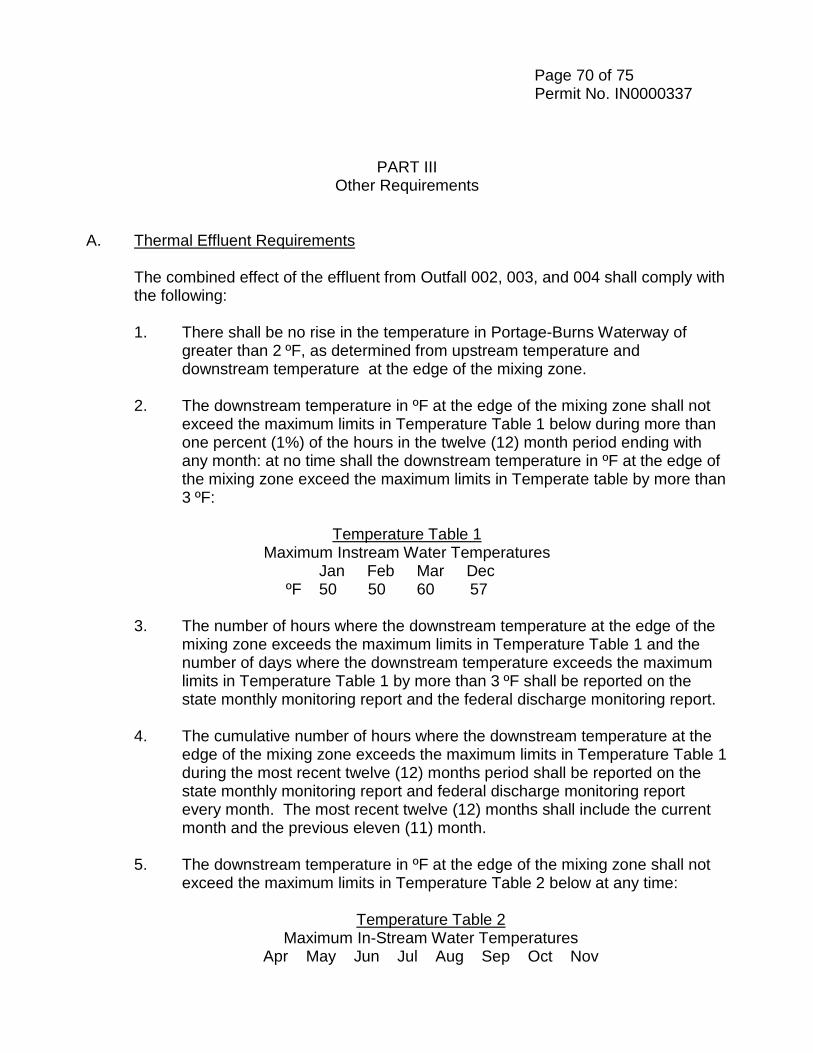
Page 70 of 75 Permit No. IN0000337
PART III Other Requirements
A. Thermal Effluent Requirements The combined effect of the effluent from Outfall 002, 003, and 004 shall comply with
the following:
1. There shall be no rise in the temperature in Portage-Burns Waterway of greater than 2 ºF, as determined from upstream temperature and downstream temperature at the edge of the mixing zone.
2. The downstream temperature in ºF at the edge of the mixing zone shall not
exceed the maximum limits in Temperature Table 1 below during more than one percent (1%) of the hours in the twelve (12) month period ending with any month: at no time shall the downstream temperature in ºF at the edge of the mixing zone exceed the maximum limits in Temperate table by more than 3 ºF:
Temperature Table 1
Maximum Instream Water Temperatures Jan Feb Mar Dec
ºF 50 50 60 57
3. The number of hours where the downstream temperature at the edge of the mixing zone exceeds the maximum limits in Temperature Table 1 and the number of days where the downstream temperature exceeds the maximum limits in Temperature Table 1 by more than 3 ºF shall be reported on the state monthly monitoring report and the federal discharge monitoring report.
4. The cumulative number of hours where the downstream temperature at the
edge of the mixing zone exceeds the maximum limits in Temperature Table 1 during the most recent twelve (12) months period shall be reported on the state monthly monitoring report and federal discharge monitoring report every month. The most recent twelve (12) months shall include the current month and the previous eleven (11) month.
5. The downstream temperature in ºF at the edge of the mixing zone shall not
exceed the maximum limits in Temperature Table 2 below at any time:
Temperature Table 2 Maximum In-Stream Water Temperatures
Apr May Jun Jul Aug Sep Oct Nov
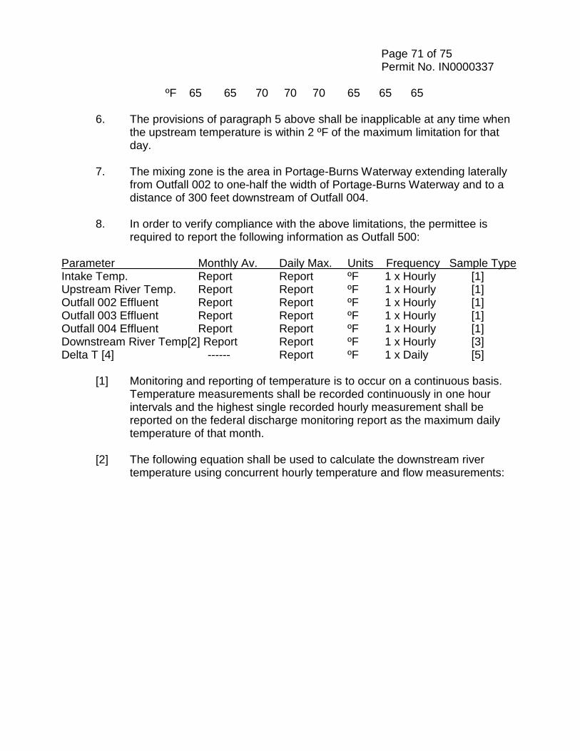
Page 71 of 75 Permit No. IN0000337
ºF 65 65 70 70 70 65 65 65 6. The provisions of paragraph 5 above shall be inapplicable at any time when
the upstream temperature is within 2 ºF of the maximum limitation for that day.
7. The mixing zone is the area in Portage-Burns Waterway extending laterally
from Outfall 002 to one-half the width of Portage-Burns Waterway and to a distance of 300 feet downstream of Outfall 004.
8. In order to verify compliance with the above limitations, the permittee is
required to report the following information as Outfall 500:
Parameter Monthly Av. Daily Max. Units Frequency Sample Type Intake Temp. Report Report ºF 1 x Hourly [1] Upstream River Temp. Report Report ºF 1 x Hourly [1] Outfall 002 Effluent Report Report ºF 1 x Hourly [1] Outfall 003 Effluent Report Report ºF 1 x Hourly [1] Outfall 004 Effluent Report Report ºF 1 x Hourly [1] Downstream River Temp[2] Report Report ºF 1 x Hourly [3] Delta T [4] ------ Report ºF 1 x Daily [5]
[1] Monitoring and reporting of temperature is to occur on a continuous basis. Temperature measurements shall be recorded continuously in one hour intervals and the highest single recorded hourly measurement shall be reported on the federal discharge monitoring report as the maximum daily temperature of that month.
[2] The following equation shall be used to calculate the downstream river
temperature using concurrent hourly temperature and flow measurements:
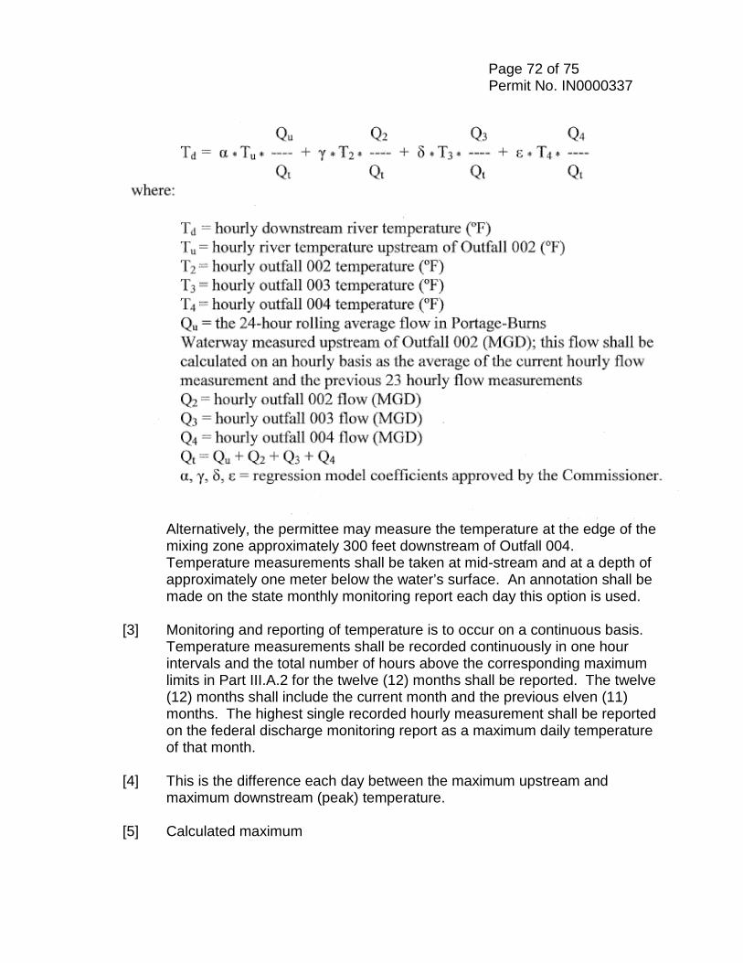
Page 72 of 75 Permit No. IN0000337
Alternatively, the permittee may measure the temperature at the edge of the mixing zone approximately 300 feet downstream of Outfall 004. Temperature measurements shall be taken at mid-stream and at a depth of approximately one meter below the water’s surface. An annotation shall be made on the state monthly monitoring report each day this option is used.
[3] Monitoring and reporting of temperature is to occur on a continuous basis.
Temperature measurements shall be recorded continuously in one hour intervals and the total number of hours above the corresponding maximum limits in Part III.A.2 for the twelve (12) months shall be reported. The twelve (12) months shall include the current month and the previous elven (11) months. The highest single recorded hourly measurement shall be reported on the federal discharge monitoring report as a maximum daily temperature of that month.
[4] This is the difference each day between the maximum upstream and
maximum downstream (peak) temperature. [5] Calculated maximum
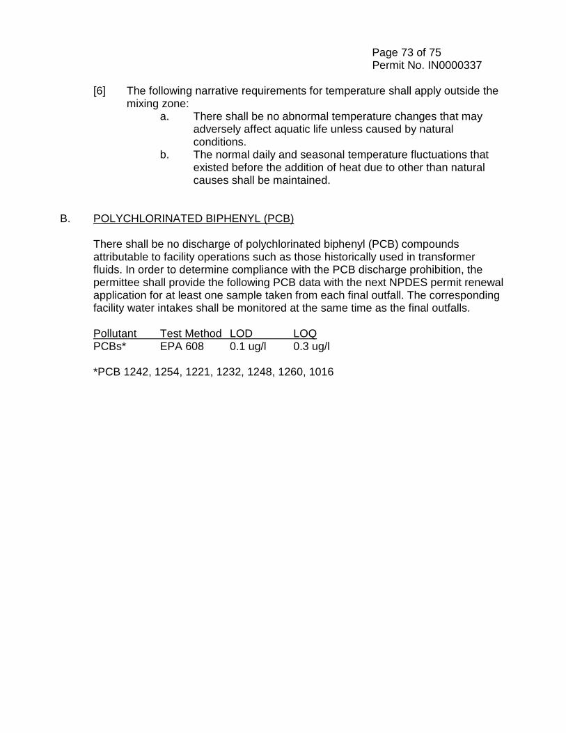
Page 73 of 75 Permit No. IN0000337
[6] The following narrative requirements for temperature shall apply outside the mixing zone:
a. There shall be no abnormal temperature changes that may adversely affect aquatic life unless caused by natural conditions.
b. The normal daily and seasonal temperature fluctuations that existed before the addition of heat due to other than natural causes shall be maintained.
B. POLYCHLORINATED BIPHENYL (PCB)
There shall be no discharge of polychlorinated biphenyl (PCB) compounds attributable to facility operations such as those historically used in transformer fluids. In order to determine compliance with the PCB discharge prohibition, the permittee shall provide the following PCB data with the next NPDES permit renewal application for at least one sample taken from each final outfall. The corresponding facility water intakes shall be monitored at the same time as the final outfalls. Pollutant Test Method LOD LOQ PCBs* EPA 608 0.1 ug/l 0.3 ug/l *PCB 1242, 1254, 1221, 1232, 1248, 1260, 1016
U. S. Steel - O & M Manual/Preventative Maintenance Program Plan – Wastewater Treatment
{B3687835.1}
Appendix I.D. NPDES Permit Part IV
Cooling Water Intake Structures
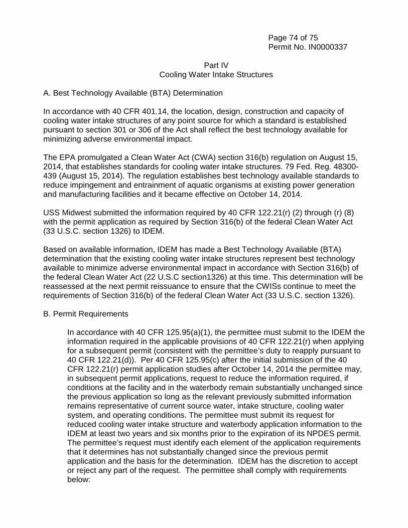
Page 74 of 75 Permit No. IN0000337
Part IV Cooling Water Intake Structures
A. Best Technology Available (BTA) Determination In accordance with 40 CFR 401.14, the location, design, construction and capacity of cooling water intake structures of any point source for which a standard is established pursuant to section 301 or 306 of the Act shall reflect the best technology available for minimizing adverse environmental impact. The EPA promulgated a Clean Water Act (CWA) section 316(b) regulation on August 15, 2014, that establishes standards for cooling water intake structures. 79 Fed. Reg. 48300-439 (August 15, 2014). The regulation establishes best technology available standards to reduce impingement and entrainment of aquatic organisms at existing power generation and manufacturing facilities and it became effective on October 14, 2014. USS Midwest submitted the information required by 40 CFR 122.21(r) (2) through (r) (8) with the permit application as required by Section 316(b) of the federal Clean Water Act (33 U.S.C. section 1326) to IDEM. Based on available information, IDEM has made a Best Technology Available (BTA) determination that the existing cooling water intake structures represent best technology available to minimize adverse environmental impact in accordance with Section 316(b) of the federal Clean Water Act (22 U.S.C section1326) at this time. This determination will be reassessed at the next permit reissuance to ensure that the CWISs continue to meet the requirements of Section 316(b) of the federal Clean Water Act (33 U.S.C. section 1326). B. Permit Requirements
In accordance with 40 CFR 125.95(a)(1), the permittee must submit to the IDEM the information required in the applicable provisions of 40 CFR 122.21(r) when applying for a subsequent permit (consistent with the permittee’s duty to reapply pursuant to 40 CFR 122.21(d)). Per 40 CFR 125.95(c) after the initial submission of the 40 CFR 122.21(r) permit application studies after October 14, 2014 the permittee may, in subsequent permit applications, request to reduce the information required, if conditions at the facility and in the waterbody remain substantially unchanged since the previous application so long as the relevant previously submitted information remains representative of current source water, intake structure, cooling water system, and operating conditions. The permittee must submit its request for reduced cooling water intake structure and waterbody application information to the IDEM at least two years and six months prior to the expiration of its NPDES permit. The permittee’s request must identify each element of the application requirements that it determines has not substantially changed since the previous permit application and the basis for the determination. IDEM has the discretion to accept or reject any part of the request. The permittee shall comply with requirements below:
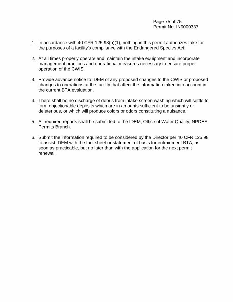
Page 75 of 75 Permit No. IN0000337
1. In accordance with 40 CFR 125.98(b)(1), nothing in this permit authorizes take for the purposes of a facility’s compliance with the Endangered Species Act.
2. At all times properly operate and maintain the intake equipment and incorporate
management practices and operational measures necessary to ensure proper operation of the CWIS.
3. Provide advance notice to IDEM of any proposed changes to the CWIS or proposed
changes to operations at the facility that affect the information taken into account in the current BTA evaluation.
4. There shall be no discharge of debris from intake screen washing which will settle to
form objectionable deposits which are in amounts sufficient to be unsightly or deleterious, or which will produce colors or odors constituting a nuisance.
5. All required reports shall be submitted to the IDEM, Office of Water Quality, NPDES
Permits Branch. 6. Submit the information required to be considered by the Director per 40 CFR 125.98
to assist IDEM with the fact sheet or statement of basis for entrainment BTA, as soon as practicable, but no later than with the application for the next permit renewal.

United States Steel O & M Manual – Waste Water Treatment
Appendix II Process Flow Diagrams
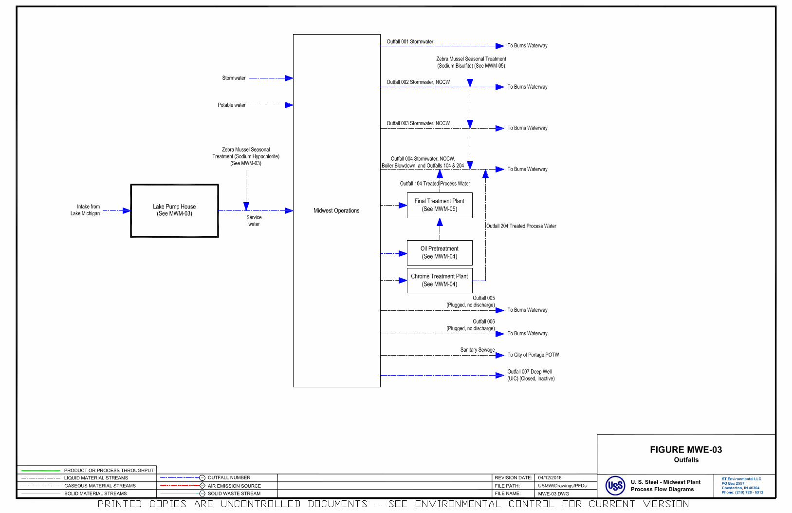
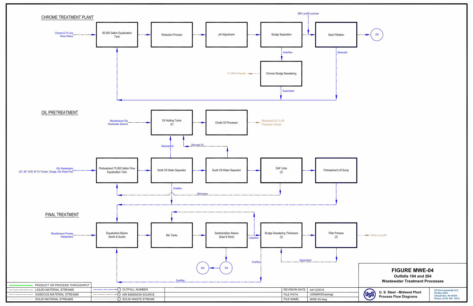
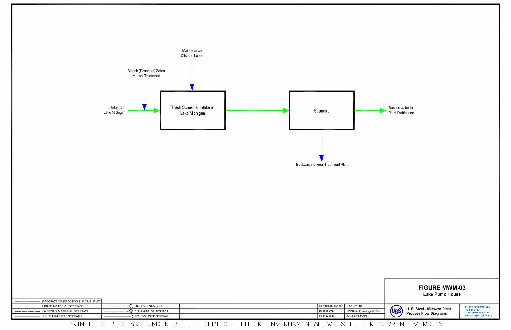
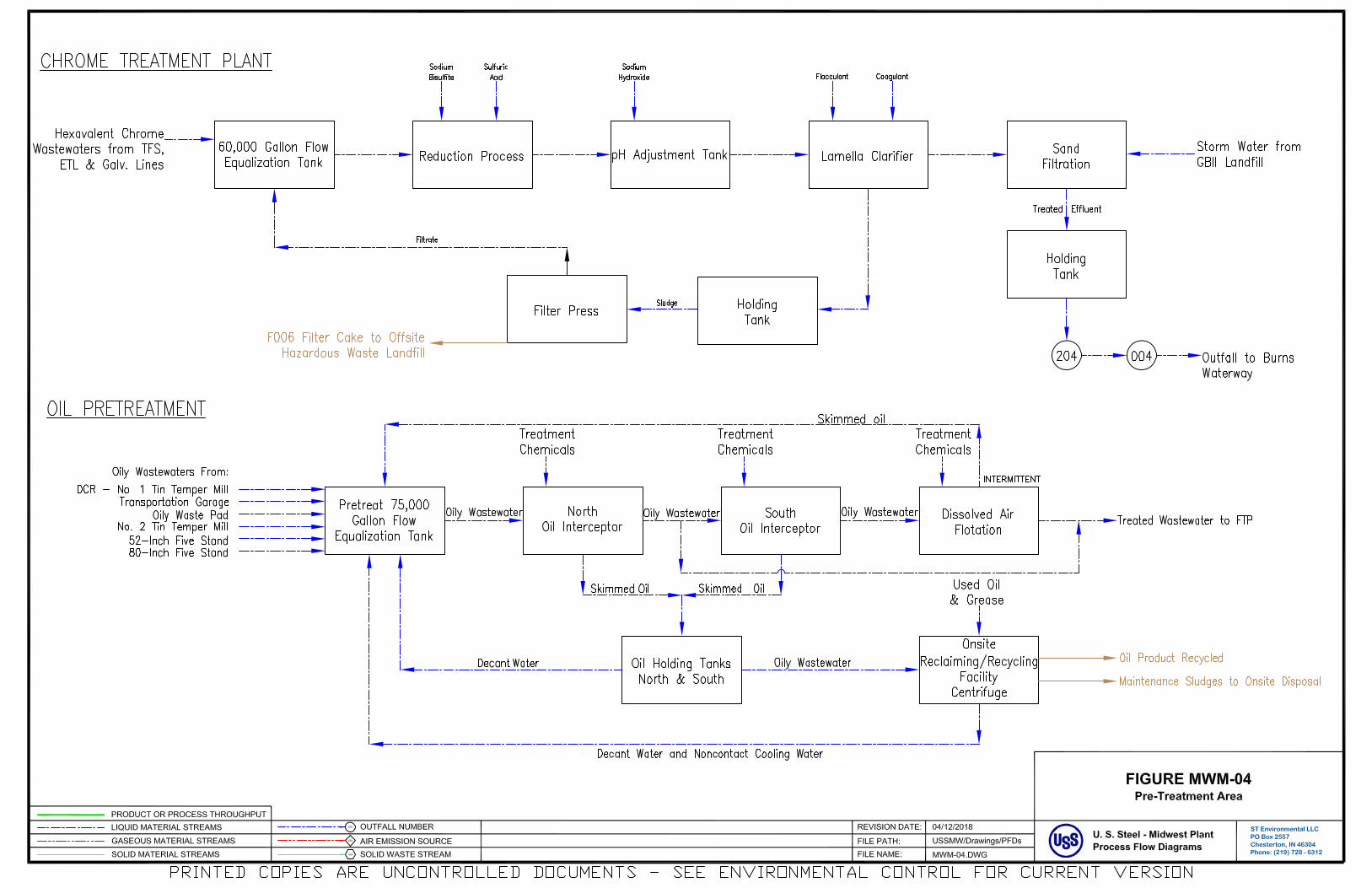
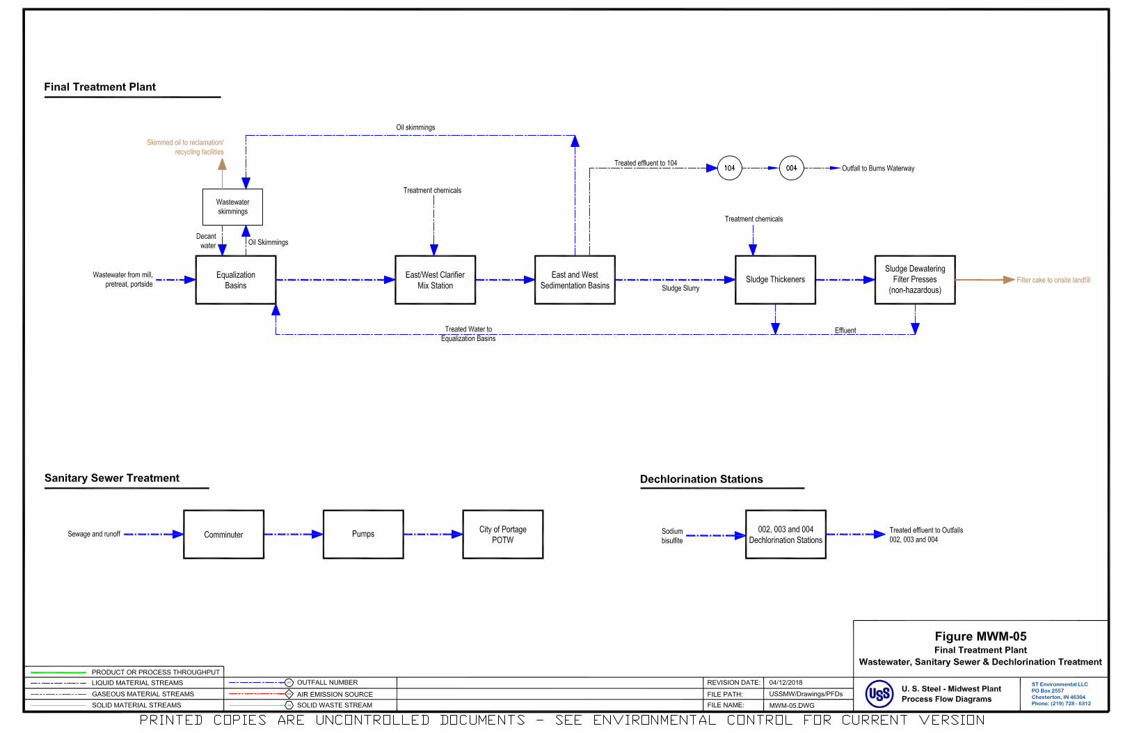
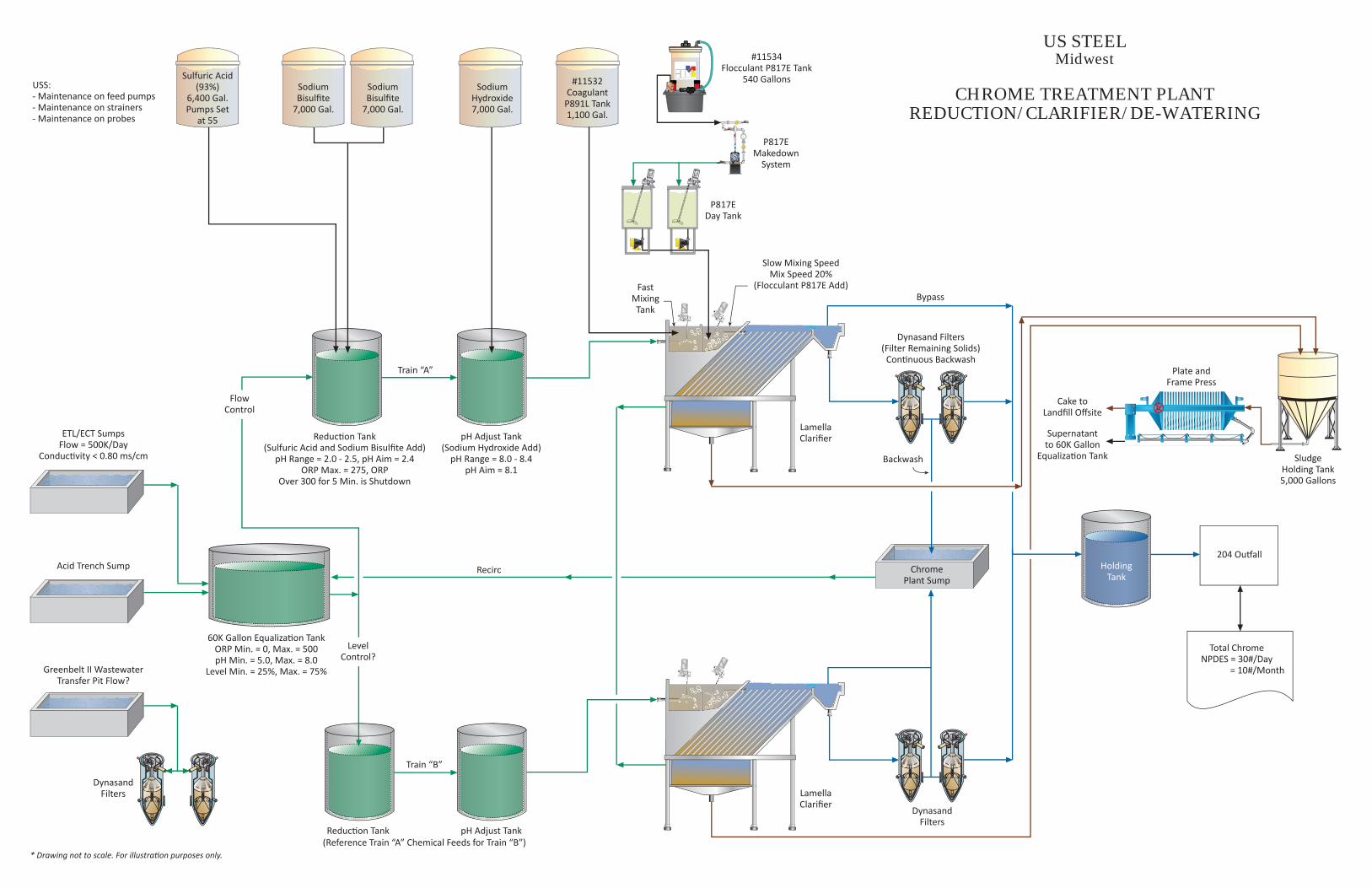
US STEELMidwest
CHROME TREATMENT PLANTREDUCTION/CLARIFIER/DE-WATERING
* Drawing not to scale. For illustra on purposes only.
Cake toLandfill Offsite
Supernatantto 60K Gallon
Equaliza on Tank
HoldingTank
Recirc
DynasandFilters
DynasandFilters
Dynasand Filters(Filter Remaining Solids)
Con nuous Backwash
LamellaClarifier
LamellaClarifier
ChromePlant Sump
Backwash
Total ChromeNPDES = 30#/Day
= 10#/Month
204 Ou all
Plate andFrame Press
SludgeHolding Tank5,000 Gallons
Bypass
Slow Mixing SpeedMix Speed 20%
(Flocculant P817E Add)FastMixingTank
P817EDay Tank
P817EMakedown
System
#11534Flocculant P817E Tank
540 Gallons#11532Coagulant
P891L Tank1,100 Gal.
Sulfuric Acid(93%)
6,400 Gal.Pumps Set
at 55
SodiumHydroxide7,000 Gal.
SodiumBisulfite
7,000 Gal.
SodiumBisulfite
7,000 Gal.
USS:- Maintenance on feed pumps- Maintenance on strainers- Maintenance on probes
ETL/ECT SumpsFlow = 500K/Day
Conduc vity < 0.80 ms/cm
60K Gallon Equaliza on TankORP Min. = 0, Max. = 500pH Min. = 5.0, Max. = 8.0
Level Min. = 25%, Max. = 75%
Reduc on Tank(Sulfuric Acid and Sodium Bisulfite Add)
pH Range = 2.0 - 2.5, pH Aim = 2.4ORP Max. = 275, ORP
Over 300 for 5 Min. is Shutdown
pH Adjust Tank(Sodium Hydroxide Add)
pH Range = 8.0 - 8.4pH Aim = 8.1
Reduc on Tank pH Adjust Tank
Acid Trench Sump
Greenbelt II WastewaterTransfer Pit Flow?
LevelControl?
FlowControl
Train “A”
Train “B”
(Reference Train “A” Chemical Feeds for Train “B”)
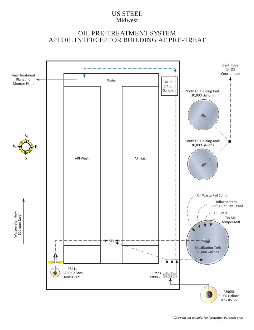
US STEELMidwest
OIL PRE-TREATMENT SYSTEMAPI OIL INTERCEPTOR BUILDING AT PRE-TREAT
* Drawing not to scale. For illustra on purposes only.
Weirs
API EastAPI West
P841L1,700 GallonsTank #5121
PumpsP8905L
P8905L5,200 GallonsTank #5122
Equaliza on Tank75,000 Gallons
Oil Waste Pad Sump
Influent From:- 80” + 52” Five Stand
South Oil Holding Tank30,000 Gallons
North Oil Holding Tank30,000 Gallons
Centrifugefor Oil
ConcentrateFinal TreatmentPlant and
Monroe Plant Oil Pit2,400
Gallons
DCR MillTin Mill
Temper Mill
Was
tew
ater
Flo
w60
0 gp
m (a
vg)
Mix
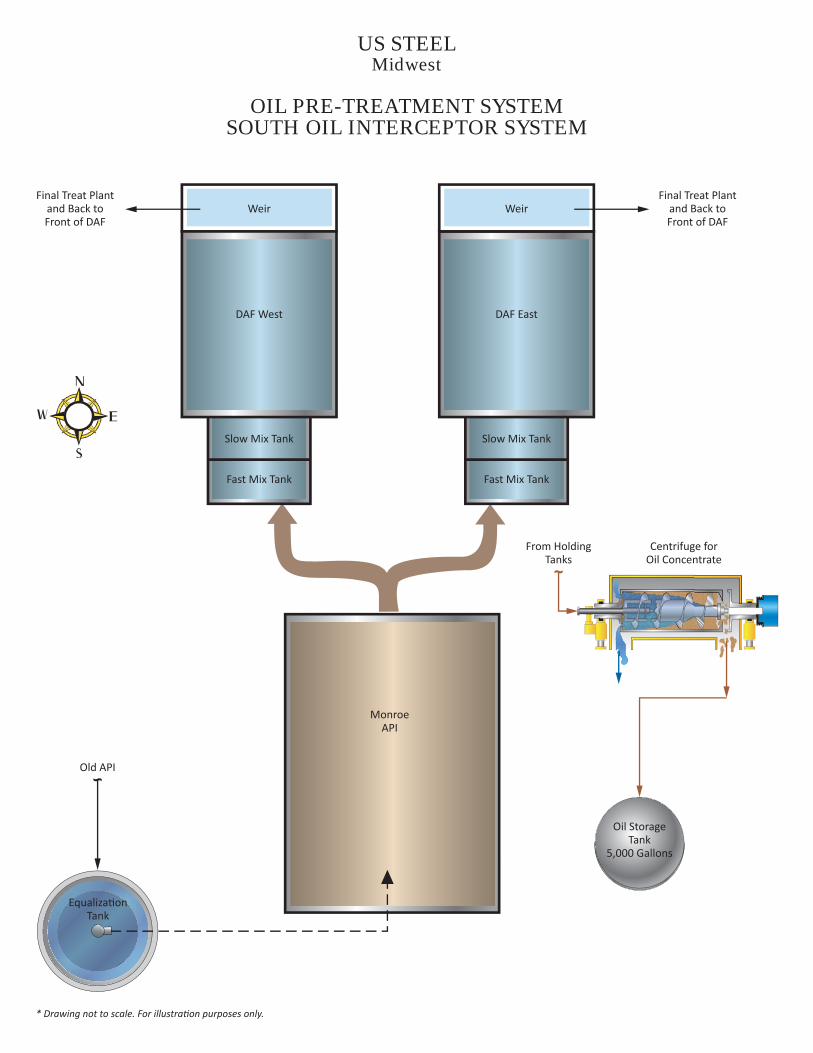
MonroeAPI
US STEELMidwest
OIL PRE-TREATMENT SYSTEMSOUTH OIL INTERCEPTOR SYSTEM
* Drawing not to scale. For illustra on purposes only.
Slow Mix Tank
Fast Mix Tank
DAF East
Slow Mix Tank
Fast Mix Tank
DAF West
Final Treat Plantand Back toFront of DAF
Final Treat Plantand Back toFront of DAF
Old API
Equaliza onTank
Oil StorageTank
5,000 Gallons
From HoldingTanks
Centrifuge forOil Concentrate
Weir Weir

US STEELMidwest
FINAL TREATMENT
* Drawing not to scale. For illustra on purposes only.
Feed: Lime, AcidRecircula on SludgepH Probe: Equaliza on Basin
A and B Mix Tank(50,700 Gallons)
❶
❷ Tank #5302 S101: 1,550 GallonsTank #5301 P891L: 1,550 Gallons
❸
❶
South Equaliza onBasin
North Equaliza onBasin
Opera ngBuilding
Air IncomingFlow
Wastewater SkimmingsTank Skimming fromSedimenta on andEqualiza on Basins.Decant the Water
Air
South LimeTank
22,500 Gallons
Tank #5120P817E
850 Gallons
SpenceBlowers
Feed P817E1% Solu on
Height = 28 . Weirs Final EffluentChannel
Tank#5118
CL240(Feed AsNeeded)
F01201,000 Gal.
PretreatLi Pumps
PretreatChannel
SulfuricAcid Tank
6,350 Gallons
North LimeTank
22,500 Gallons
❷
Air MixTanks
Distribu onChannel
Floccula onArea
CrossCollectors
North andSouth
104Ou all
004Ou all
pH = 6 - 9Limit
Sludge is Collected and Sentto SDW Plant and Recircula on
West Sedimenta on Basin
East Sedimenta on Basin
Height = 20 .
Weirs
❸
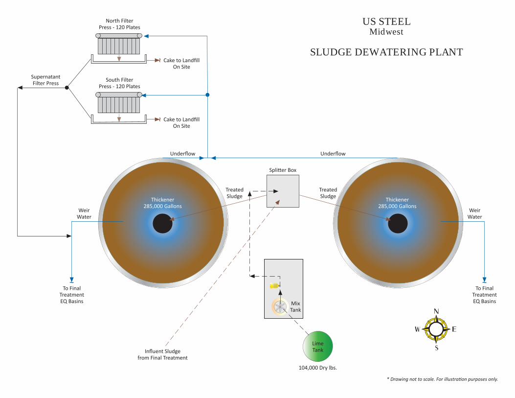
US STEELMidwest
SLUDGE DEWATERING PLANT
* Drawing not to scale. For illustra on purposes only.
Thickener285,000 Gallons
Thickener285,000 Gallons
Underflow Underflow
104,000 Dry lbs.
To FinalTreatmentEQ Basins
To FinalTreatmentEQ Basins
Cake to LandfillOn Site
Cake to LandfillOn Site
SupernatantFilter Press
WeirWater
WeirWater
TreatedSludge
TreatedSludge
Spli er Box
Influent Sludgefrom Final Treatment
LimeTank
MixTank
North FilterPress - 120 Plates
South FilterPress - 120 Plates
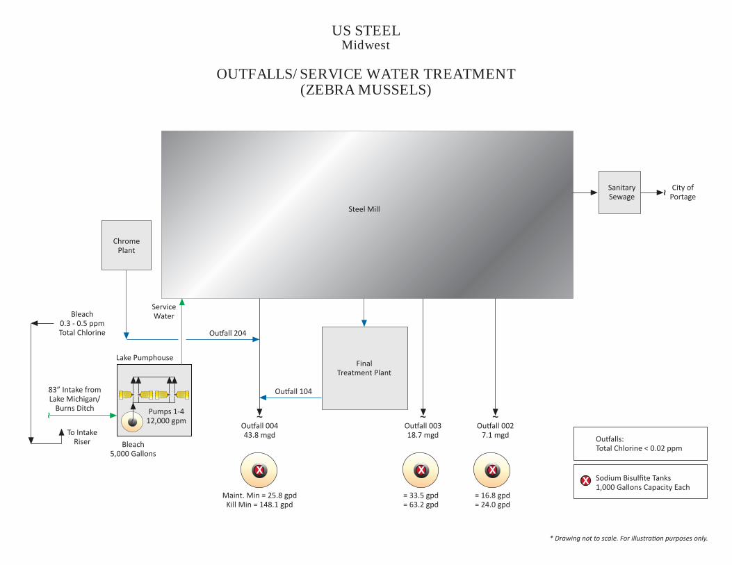
US STEELMidwest
OUTFALLS/SERVICE WATER TREATMENT(ZEBRA MUSSELS)
* Drawing not to scale. For illustra on purposes only.
Steel Mill
SanitarySewage
City ofPortage
ChromePlant
Ou all 104
Ou all 204
FinalTreatment Plant
Ou all 0027.1 mgd
Ou all 00318.7 mgd
Ou all 00443.8 mgd
Maint. Min = 25.8 gpdKill Min = 148.1 gpd
= 33.5 gpd= 63.2 gpd
= 16.8 gpd= 24.0 gpd
Ou alls:Total Chlorine < 0.02 ppm
Sodium Bisulfite Tanks1,000 Gallons Capacity Each
ServiceWaterBleach
0.3 - 0.5 ppmTotal Chlorine
83” Intake fromLake Michigan/
Burns Ditch
To IntakeRiser
Lake Pumphouse
Pumps 1-412,000 gpm
Bleach5,000 Gallons