unity pro system block library -...
TRANSCRIPT

3300
2539
.02
Unity ProSystemBlock Library
June 2005

2

Table of Contents
About the Book . . . . . . . . . . . . . . . . . . . . . . . . . . . . . . . . . . . . . . .7
Part I General information . . . . . . . . . . . . . . . . . . . . . . . . . . . . . . 9Introduction . . . . . . . . . . . . . . . . . . . . . . . . . . . . . . . . . . . . . . . . . . . . . . . . . . . . . . 9
Chapter 1 Block types and their applications . . . . . . . . . . . . . . . . . . . . . . 11Introduction . . . . . . . . . . . . . . . . . . . . . . . . . . . . . . . . . . . . . . . . . . . . . . . . . . . . . 11Block types . . . . . . . . . . . . . . . . . . . . . . . . . . . . . . . . . . . . . . . . . . . . . . . . . . . . . 12FFB Structure . . . . . . . . . . . . . . . . . . . . . . . . . . . . . . . . . . . . . . . . . . . . . . . . . . . 13EN and ENO . . . . . . . . . . . . . . . . . . . . . . . . . . . . . . . . . . . . . . . . . . . . . . . . . . . . 16
Chapter 2 Availability of the function block on different hardware platforms . . . . . . . . . . . . . . . . . . . . . . . .19Introduction . . . . . . . . . . . . . . . . . . . . . . . . . . . . . . . . . . . . . . . . . . . . . . . . . . . . . 23
Chapter 3 HALT: Stopping the program . . . . . . . . . . . . . . . . . . . . . . . . . .25
Chapter 4 ITCNTRL : Triggering of TIMER type event processing . . . . . 27
Chapter 5 MASKEVT: Global masking of events . . . . . . . . . . . . . . . . . . .31
Chapter 6 UNMASKEVT: Global unmasking of events. . . . . . . . . . . . . . . 33
Part III Hot Stand By. . . . . . . . . . . . . . . . . . . . . . . . . . . . . . . . . . . 35Introduction . . . . . . . . . . . . . . . . . . . . . . . . . . . . . . . . . . . . . . . . . . . . . . . . . . . . . 35
Chapter 7 HSBY_RD: Reading the Hot Standby command register . . . . . . . . . . . . . . . . . . . . . . . . . . . . . . . . . . . . . . . . . . . . 37
Chapter 8 HSBY_ST: Reading the Hot Standby status register . . . . . . . 41
Chapter 9 HSBY_WR: Writing to the Hot Standby command register. . . . . . . . . . . . . . . . . . . . . . . . . . . . . . . . . . . . . . . . . . . . .45
Chapter 10 REV_XFER: Writing and reading the two Reverse-Transfer-Registers. . . . . . . . . . . . . . . . . . . . . . . . . . . . 49
3

Part IV SFC Management. . . . . . . . . . . . . . . . . . . . . . . . . . . . . . . . 53Introduction . . . . . . . . . . . . . . . . . . . . . . . . . . . . . . . . . . . . . . . . . . . . . . . . . . . . . 53
Chapter 11 CLEARCHART: Reset all active steps . . . . . . . . . . . . . . . . . . . 55
Chapter 12 FREEZECHART: Freeze sequence . . . . . . . . . . . . . . . . . . . . . . 59
Chapter 13 INITCHART: Reset all active steps and start sequence normally . . . . . . . . . . . . . . . . . . . . . . . . . . 63
Chapter 14 RESETSTEP: Reset a specific step in the sequence . . . . . . . 67
Chapter 15 SETSTEP: Set a specific step in the sequence. . . . . . . . . . . . 69
Chapter 16 SFCCNTRL: SFC Control . . . . . . . . . . . . . . . . . . . . . . . . . . . . . 71Overview . . . . . . . . . . . . . . . . . . . . . . . . . . . . . . . . . . . . . . . . . . . . . . . . . . . . . . . 71Description . . . . . . . . . . . . . . . . . . . . . . . . . . . . . . . . . . . . . . . . . . . . . . . . . . . . . . 72Parameter description . . . . . . . . . . . . . . . . . . . . . . . . . . . . . . . . . . . . . . . . . . . . . 77
Part V SysClock. . . . . . . . . . . . . . . . . . . . . . . . . . . . . . . . . . . . . . . 83Introduction . . . . . . . . . . . . . . . . . . . . . . . . . . . . . . . . . . . . . . . . . . . . . . . . . . . . . 83
Chapter 17 FREERUN: Free-running timer . . . . . . . . . . . . . . . . . . . . . . . . . 85
Chapter 18 PTC: Reading the stop date and code . . . . . . . . . . . . . . . . . . . 87
Chapter 19 RRTC_DT: Reading the system date . . . . . . . . . . . . . . . . . . . . 89
Chapter 20 R_NTPC: Network real-time clock function. . . . . . . . . . . . . . . 91
Chapter 21 SCHEDULE: Real-time clock function . . . . . . . . . . . . . . . . . . . 95
Chapter 22 WRTC_DT: Updating the system date . . . . . . . . . . . . . . . . . . . 99
4
Appendices . . . . . . . . . . . . . . . . . . . . . . . . . . . . . . . . . . . . . . . . . . . . . 101Introduction . . . . . . . . . . . . . . . . . . . . . . . . . . . . . . . . . . . . . . . . . . . . . . . . . . . . 101
Appendix A System objects . . . . . . . . . . . . . . . . . . . . . . . . . . . . . . . . . . . . .103At a Glance . . . . . . . . . . . . . . . . . . . . . . . . . . . . . . . . . . . . . . . . . . . . . . . . . . . . 103System bit introduction . . . . . . . . . . . . . . . . . . . . . . . . . . . . . . . . . . . . . . . . . . . 104Description of system bits %S0 to %S7 . . . . . . . . . . . . . . . . . . . . . . . . . . . . . . 105Description of system bits %S15 to %S21 . . . . . . . . . . . . . . . . . . . . . . . . . . . . 106Description of system bits %S30 to %S59 . . . . . . . . . . . . . . . . . . . . . . . . . . . . 109Description of system words %SW12 to %SW18 . . . . . . . . . . . . . . . . . . . . . . . 112Description of system words %SW48 to %SW59 . . . . . . . . . . . . . . . . . . . . . . . 114Description of System Words %SW60 to %SW63: . . . . . . . . . . . . . . . . . . . . . . 116
Glossary . . . . . . . . . . . . . . . . . . . . . . . . . . . . . . . . . . . . . . . . . . . . . 119
Index . . . . . . . . . . . . . . . . . . . . . . . . . . . . . . . . . . . . . . . . . . . . . 135
5

6
About the Book
At a Glance
Document Scope This document describes the functions and function blocks of the System library.This document is valid for Unity Pro Version 2.1.
Validity Note The data and illustrations found in this document are not binding. We reserve the right to modify our products in line with our policy of continuous product development. The information in this document is subject to change without notice and should not be construed as a commitment by Schneider Electric.
Product Related Warnings
Schneider Electric assumes no responsibility for any errors that may appear in this document. If you have any suggestions for improvements or amendments or have found errors in this publication, please notify us. No part of this document may be reproduced in any form or by any means, electronic or mechanical, including photocopying, without express written permission of Schneider Electric.All pertinent state, regional, and local safety regulations must be observed when installing and using this product. For reasons of safety and to ensure compliance with documented system data, only the manufacturer should perform repairs to components.When controllers are used for applications with technical safety requirements, please follow the relevant instructions.Failure to use Schneider Electric software or approved software with our hardware products may result in injury, harm, or improper operating results.Failure to observe this product related warning can result in injury or equipment damage.
User Comments We welcome your comments about this document. You can reach us by e-mail at [email protected]
7

About the Book
8

I
General informationIntroduction
Overview This section provides general information on the System library
What's in this Part?
This part contains the following chapters:
Chapter Chapter Name Page
1 Block types and their applications 11
2 Availability of the function block on different hardware platforms
19
9

General information
10
1
Block types and their applicationsIntroduction
Overview This chapter describes the different block types and their applications.
What's in this Chapter?
This chapter contains the following topics:
Topic Page
Block types 12
FFB Structure 13
EN and ENO 16
11
Block types and their applications
Block types
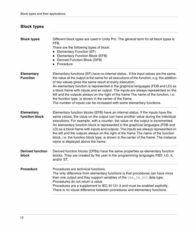
Block types Different block types are used in Unity Pro. The general term for all block types is FFB.There are the following types of block:� Elementary Function (EF)� Elementary Function Block (EFB)� Derived Function Block (DFB)� Procedure
Elementary Function
Elementary functions (EF) have no internal status.. If the input values are the same, the value at the output is the same for all executions of the function, e.g. the addition of two values gives the same result at every execution.An elementary function is represented in the graphical languages (FDB and LD) as a block frame with inputs and an output. The inputs are always represented on the left and the outputs always on the right of the frame The name of the function, i.e. the function type, is shown in the center of the frame.The number of inputs can be increased with some elementary functions.
Elementary function block
Elementary function blocks (EFB) have an internal status. If the inputs have the same values, the value on the output can have another value during the individual executions. For example, with a counter, the value on the output is incremented.An elementary function block is represented in the graphical languages (FDB and LD) as a block frame with inputs and outputs. The inputs are always represented on the left and the outputs always on the right of the frame The name of the function block, i.e. the function block type, is shown in the center of the frame. The instance name is displayed above the frame.
Derived function block
Derived function blocks (DFBs) have the same properties as elementary function blocks. They are created by the user in the programming languages FBD, LD, IL and/or ST.
Procedure Procedures are technical functions.The only difference from elementary functions is that procedures can have more than one output and they support variables of the VAR_IN_OUT data type.Procedures do not return a value.Procedures are a supplement to IEC 61131-3 and must be enabled explicitly.There is no visual difference between procedures and elementary functions.
12

Block types and their applications
FFB Structure
Structure Each FFB is made up of an operation (name of the FFB), the operands required for the operation (formal and actual parameters) and an instance name for elementary/derived function blocks.Call of a function block in the FBD programming language:
Formal call of a function block in the ST programming language:
Operation The operation determines which function is to be executed with the FFB, e.g. shift register, conversion operations.
Instance Name Operation(FFB name)
Operand
Formal parameter
TON
ENABLE
EXAMP
TIME1
EN
IN
PT
ENO
Q
ET
ERROR
OUT
TIME2
MY_TON
Actual parameter
Instance NameFormal parameters (inputs)
MY_TON (EN:=ENABLE, IN:=EXAMP, PT:=TIME1, ENO=>ERROR, Q=>OUT, ET=>TIME2);
Actual parameters (inputs)
Formal parameters (outputs)
Actual parameters (outputs)
Operands
Operands
13

Block types and their applications
Operand The operand specifies what the operation is to be executed with. With FFBs, this consists of formal and actual parameters.
Formal/actual parameters
Inputs and outputs are required to transfer values to or from an FFB. These are called formal parameters.Objects are linked to formal parameters; these objects contain the current process states. They are called actual parameters.At program runtime, the values from the process are transferred to the FFB via the actual parameters and then output again after processing. The data type of the actual parameters must match the data type of the input/output (formal parameters). The only exceptions are generic inputs/outputs whose data type is determined by the actual parameter. If all actual parameters consist of literals, a suitable data type is selected for the function block.
FFB Call in IL/ST In text languages IL and ST, FFBs can be called in formal and in informal form. Details can be found in the Reference manual.Example of a formal function call:out:=LIMIT (MN:=0, IN:=var1, MX:=5) ;Example of an informal function call:out:=LIMIT (0, var1, 5) ;
Note: Take note that the use of EN and ENO is only possible for formal calls.
14
Block types and their applications
VAR_IN_OUT variable
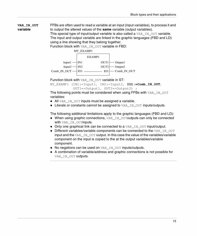
FFBs are often used to read a variable at an input (input variables), to process it and to output the altered values of the same variable (output variables).This special type of input/output variable is also called a VAR_IN_OUT variable.The input and output variable are linked in the graphic languages (FBD and LD) using a line showing that they belong together.Function block with VAR_IN_OUT variable in FBD:
Function block with VAR_IN_OUT variable in ST:MY_EXAMP1 (IN1:=Input1, IN2:=Input2, IO1:=Comb_IN_OUT,
OUT1=>Output1, OUT2=>Output2) ; The following points must be considered when using FFBs with VAR_IN_OUT variables: � All VAR_IN_OUT inputs must be assigned a variable.� Literals or constants cannot be assigned to VAR_IN_OUT inputs/outputs.
The following additional limitations apply to the graphic languages (FBD and LD): � When using graphic connections, VAR_IN_OUToutputs can only be connected
with VAR_IN_OUTinputs. � Only one graphical link can be connected to a VAR_IN_OUT input/output.� Different variables/variable components can be connected to the VAR_IN_OUT
input and the VAR_IN_OUT output. In this case the value of the variables/variable component on the input is copied to the at the output variables/variable component.
� No negations can be used on VAR_IN_OUT inputs/outputs.� A combination of variable/address and graphic connections is not possible for
VAR_IN_OUT outputs.
EXAMP1
Comb_IN_OUTIO1
IN1Input1
IN2Input2
IO1Comb_IN_OUT
MY_EXAMP1
Output1OUT1
Output2OUT2
15
Block types and their applications
EN and ENO
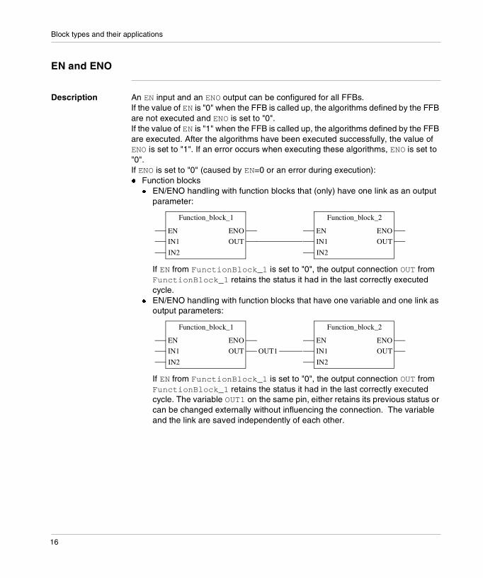
Description An EN input and an ENO output can be configured for all FFBs.If the value of EN is "0" when the FFB is called up, the algorithms defined by the FFB are not executed and ENO is set to "0".If the value of EN is "1" when the FFB is called up, the algorithms defined by the FFB are executed. After the algorithms have been executed successfully, the value of ENO is set to "1". If an error occurs when executing these algorithms, ENO is set to "0".If ENO is set to "0" (caused by EN=0 or an error during execution):� Function blocks
� EN/ENO handling with function blocks that (only) have one link as an output parameter:
If EN from FunctionBlock_1 is set to "0", the output connection OUT from FunctionBlock_1 retains the status it had in the last correctly executed cycle.
� EN/ENO handling with function blocks that have one variable and one link as output parameters:
If EN from FunctionBlock_1 is set to "0", the output connection OUT from FunctionBlock_1 retains the status it had in the last correctly executed cycle. The variable OUT1 on the same pin, either retains its previous status or can be changed externally without influencing the connection. The variable and the link are saved independently of each other.
Function_block_1
EN
IN2
ENO
IN1 OUT
Function_block_2
EN
IN2
ENO
IN1 OUT
Function_block_1
EN
IN2
ENO
IN1 OUT
Function_block_2
EN
IN2
ENO
IN1 OUTOUT1
16

Block types and their applications
� Functions/ProceduresAs defined in IEC61131-3, the outputs from deactivated functions (EN-input set to "0") is undefined. (The same applies to procedures.) Here nevertheless an explanation of the output statuses in this case:� EN/ENO handling with function/procedure blocks that (only) have one link as
an output parameter:
If EN from Function/Procedure_1 is set to "0", the output connection OUT from Function/Procedure_1 is also set to "0".
� EN/ENO handling with function/procedure blocks that have one variable and one link as output parameters:
If EN from Function/Procedure_1 is set to "0", the output connection OUT from Function/Procedure_1 is also set to "0", however the variable OUT1 on the same pin retains its previous value. In this way it is possible for the variable and the link to have different values.
The output behavior of the FFBs does not depend on whether the FFBs are called up without EN/ENO or with EN=1.
Conditional/Unconditional FFB Call
"Unconditional" or "conditional" calls are possible with each FFB. The condition is realized by pre-linking the input EN.� EN connected
conditional calls (the FFB is only processed if EN = 1)� EN shown, hidden, and marked TRUE, or shown and not occupied
unconditional calls (FFB is always processed)
Note for IL and ST
The use of EN and ENO is only possible in the text languages for a formal FFB call, e.g.MY_BLOCK (EN:=enable, IN1:=var1, IN2:=var2,ENO=>error, OUT1=>result1, OUT2=>result2);Assigning the variables to ENO must be done with the operator =>.With an informal call, EN and ENO cannot be used.
Function/Procedure_1
EN
IN2
ENO
IN1 OUT
Function/Procedure_2
EN
IN2
ENO
IN1 OUT
Function/Procedure_1
EN
IN2
ENO
IN1 OUT
Function/Procedure_2
EN
IN2
ENO
IN1 OUTOUT1
17

Block types and their applications
18

2
Availability of the function block on different hardware platformsAvailability of the block on the various hardware platforms
Introduction Not all blocks are available on all hardware platforms. The blocks available on your hardware platform can be found in the following tables.
Events Availability of the blocks:
Note: The functions and function blocks in this library are not defined in IEC 61131-3.
Block name Block type Premium Quantum
HALT Procedure + +
ITCNTRL Procedure + +
MASKEVT Procedure + +
UNMASKEVT Procedure + +
Legend:
+ Yes
- No
19

Availability of the function block
Hot Standby Availability of the blocks:
SFC Management
Availability of the blocks:
Block name Block type Premium Quantum
HSBY_RD EFB - 140 CPU 671 60
HSBY_ST EFB - 140 CPU 671 60
HSBY_WR EFB - 140 CPU 671 60
REV_XFER EFB - 140 CPU 671 60
Legend:
+ Yes
- No
Block name Block type Premium Quantum
CLEARCHART EF + +
FREEZECHART EF + +
INITCHART EF + +
RESETSTEP Procedure + +
SETSTEP Procedure + +
SFCCNTRL EFB + +
Legend:
+ Yes
- No
20
Availability of the function block
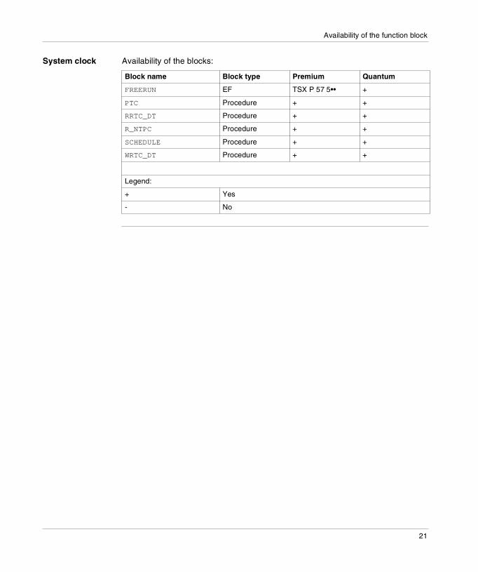
System clock Availability of the blocks:
Block name Block type Premium Quantum
FREERUN EF TSX P 57 5•• +
PTC Procedure + +
RRTC_DT Procedure + +
R_NTPC Procedure + +
SCHEDULE Procedure + +
WRTC_DT Procedure + +
Legend:
+ Yes
- No
21

Availability of the function block
22
II
EventsIntroduction
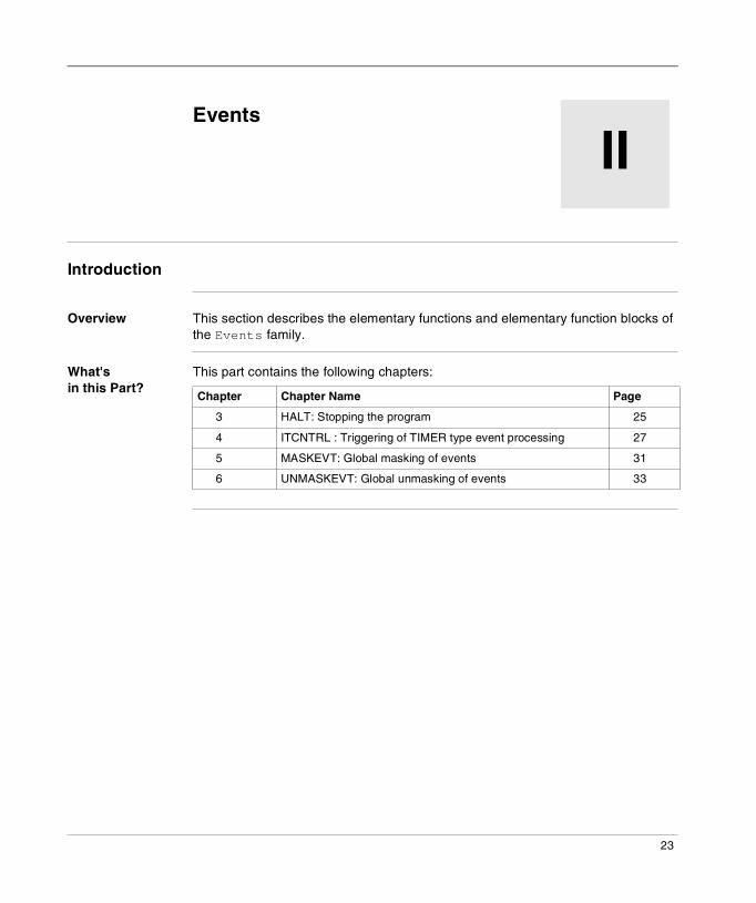
Overview This section describes the elementary functions and elementary function blocks of the Events family.
What's in this Part?
This part contains the following chapters:
Chapter Chapter Name Page
3 HALT: Stopping the program 25
4 ITCNTRL : Triggering of TIMER type event processing 27
5 MASKEVT: Global masking of events 31
6 UNMASKEVT: Global unmasking of events 33
23

Events
24

3
HALT: Stopping the programDescription
Description of the function
The HALT function in an application program can be used to halt its execution (stop all tasks), which effectively freezes the variable objects of this program.
In order for execution to resume, a program halted in this way must be initialized (using the INIT command). The instructions that follow the HALT instruction are therefore not executed.Caution; when the PLC is in HALT, all tasks are stopped. Check the behavior of the associated I/Os.
The additional parameters EN and ENO can be configured.
FBD representation
Representation:
LD representation
Representation:
HALT
ENOEN
HALT
ENOEN
25
HALT
IL representation Representation:HALT
ST representation
Representation:HALT();
26
4
ITCNTRL : Triggering of TIMER type event processingDescription
Description of the function
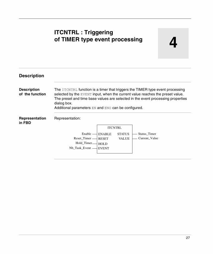
The ITCNTRL function is a timer that triggers the TIMER type event processing selected by the EVENT input, when the current value reaches the preset value.The preset and time base values are selected in the event processing properties dialog box.Additional parameters EN and ENO can be configured.
Representation in FBD
Representation:
ITCNTRL
Enable Status_TimerReset_Timer Current_Value
Hold_Timer
Nb_Task_Event
STATUSENABLERESET
EVENTHOLD
VALUE
27
ITCNTRL
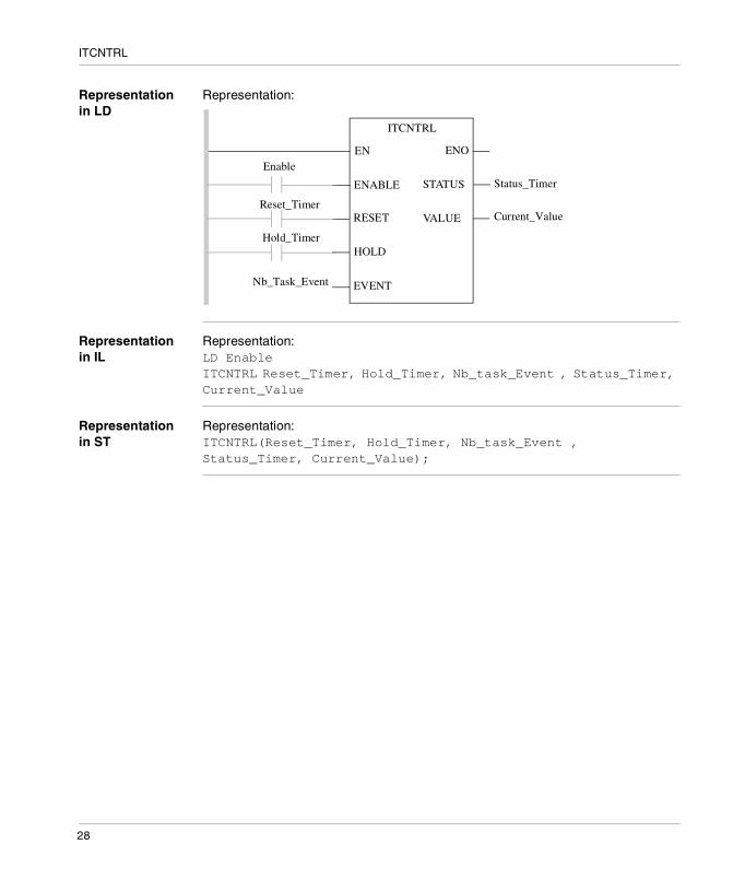
Representation in LD
Representation:
Representation in IL
Representation:LD EnableITCNTRL Reset_Timer, Hold_Timer, Nb_task_Event , Status_Timer, Current_Value
Representation in ST
Representation:ITCNTRL(Reset_Timer, Hold_Timer, Nb_task_Event , Status_Timer, Current_Value);
Status_Timer
Current_Value
ITCNTRL
Enable
Reset_Timer
Hold_Timer
Nb_Task_Event
ENOEN
STATUSENABLE
RESET
EVENT
HOLD
VALUE
28

ITCNTRL
Description of the parameters
The following table describes the input parameters:
The following table describes the output parameters:
Parameter Type Comment
Enable BOOL Enable input selected,.on state 1: the event processing is triggered when the timer has elapsed. on state 0: no event is emitted
Reset_Timer BOOL On state 1 reset the timer
Hold_Timer BOOL On state 1 freeze the timer incrementation.
Nb_Task_Event BYTE Input word which determines the TIMER event processing number to be triggered.
Parameter Type Comment
Status_Timer WORD Status word :� bit0 = 1 execution delayed by a masking of the interruption.� bit 1 =1 event processing number not valid� bit 2 = 1 validated timer (Enable input image).� bit 3 = 1 "frozen" timer (Hold_Timer input image).� bit 4 =1 as soon as ITCNTRL is called the first time with the
input Reset_Timer or Hold_Timer at 1 (out-of-phase mode). It is reset to 0 on a cold start.
� bit 5 = 1 FIFO memory stack of the saturated interruptions.
Current_Value TIME Current timer value.This value is increased by 0 to the preset value. When the preset value is reached, it is reset to 0. If the associated TIMER type event processing is confirmed, it is executed.
29

ITCNTRL
30
5
MASKEVT: Global masking of eventsDescription
Description of the function
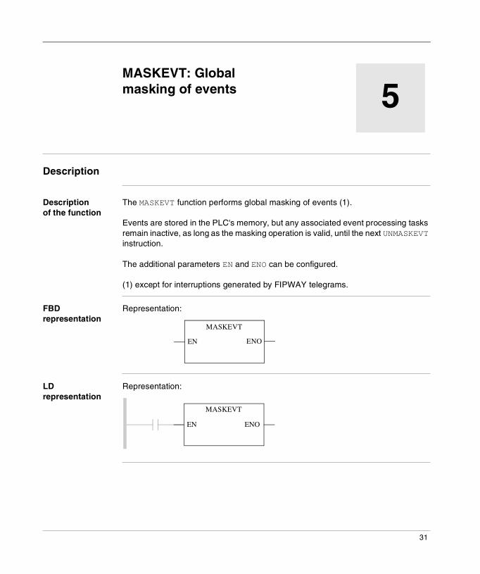
The MASKEVT function performs global masking of events (1).
Events are stored in the PLC's memory, but any associated event processing tasks remain inactive, as long as the masking operation is valid, until the next UNMASKEVT instruction.
The additional parameters EN and ENO can be configured.
(1) except for interruptions generated by FIPWAY telegrams.
FBD representation
Representation:
LD representation
Representation:
MASKEVT
ENOEN
ENOEN
MASKEVT
31

MASKEVT
IL representation Representation:MASKEVT
ST representation
Representation:MASKEVT();
32
6
UNMASKEVT: Global unmasking of eventsDescription
Description of the function
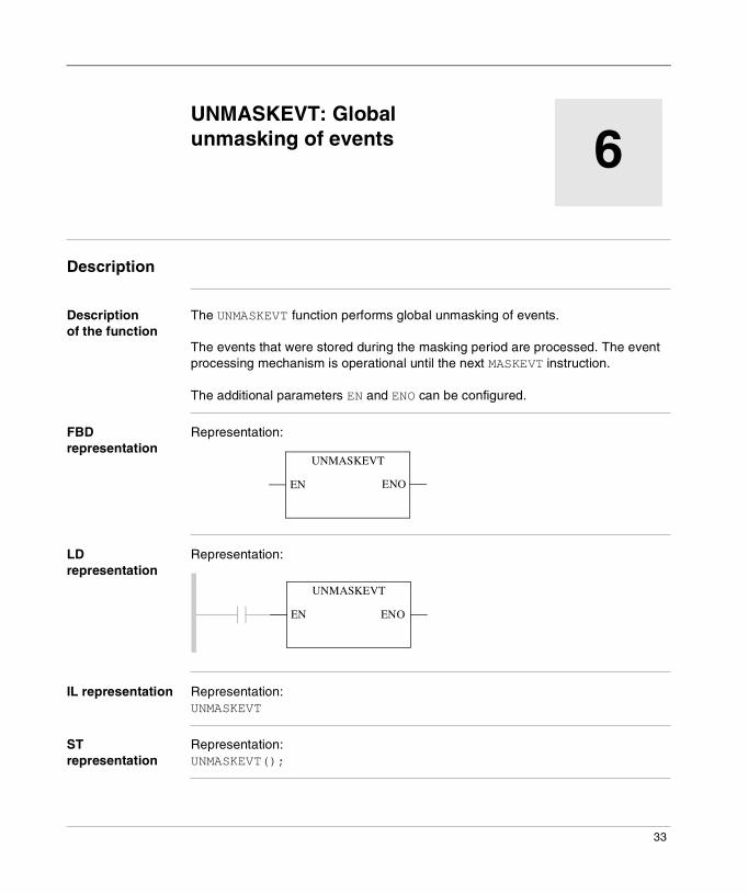
The UNMASKEVT function performs global unmasking of events.
The events that were stored during the masking period are processed. The event processing mechanism is operational until the next MASKEVT instruction.
The additional parameters EN and ENO can be configured.
FBD representation
Representation:
LD representation
Representation:
IL representation Representation:UNMASKEVT
ST representation
Representation:UNMASKEVT();
UNMASKEVT
ENOEN
ENOEN
UNMASKEVT
33

UNMASKEVT
34

III
Hot Stand ByIntroduction
Overview This section describes the elementary functions and elementary function blocks of the Hot Stand By family.
What's in this Part?
This part contains the following chapters:
Chapter Chapter Name Page
7 HSBY_RD: Reading the Hot Standby command register 37
8 HSBY_ST: Reading the Hot Standby status register 41
9 HSBY_WR: Writing to the Hot Standby command register 45
10 REV_XFER: Writing and reading the two Reverse-Transfer-Registers
49
35

Hot Stand By
36

7
HSBY_RD: Reading the Hot Standby command registerDescription: HSBY_RD
Function description
This EFB allows you to use the Hot Standby function. It searches (together with other EFBs in the Hot Standby family) the configuration of the respective Quantum PLC for the required components. These components always refer to hardware that is actually connected.Therefore the correct behavior of this EFB on the simulators cannot be guaranteed. The EFB HSBY_RD independently checks if a Hot Standby configuration exists (%SW60 (See Detailed Description, p. 116)). If a configuration is present the contents of the command register are given and the HSBY output is set to "1". If there is no Hot Standby configuration present the output is set to "0".EN and ENO can be configured as additional parameters.
Representation in FBD
Representation:
HSBY_ConfigurationFound
HSBY_RD
InvalidateKeypadPLC_A_Running
PLC_B_Running
StandbyOff
ExecUpdateSwapAddressModbusPort1
HSBY
INV_KEY
PCA_RUN
PCB_RUN
SBY_OFF
EXC_UPD
SWP_MB1
SWP_MB2
SWP_MB3
HSBY_RD_Instance
37

HSBY_RD
Representation in LD
Representation:
Representation in IL
Representation:CAL HSBY_RD_Instance (HSBY=>HSBY_ConfigurationFound, INV_KEY=>InvalidateKeypad, PCA_RUN=>PLC_A_Running, PCB_RUN=>PLC_B_Running, SBY_OFF=>StandbyOff, EXC_UPD=>ExecUpdate, SWP_MB1=>SwapAddressModbusPort1)
Representation in ST
Representation:HSBY_RD_Instance (HSBY=>HSBY_ConfigurationFound, INV_KEY=>InvalidateKeypad, PCA_RUN=>PLC_A_Running, PCB_RUN=>PLC_B_Running, SBY_OFF=>StandbyOff, EXC_UPD=>ExecUpdate, SWP_MB1=>SwapAddressModbusPort1);
ENOEN
HSBY_ConfigurationFound
HSBY_RD
InvalidateKeypad
PLC_A_Running
PLC_B_Running
StandbyOff
ExecUpdate
SwapAddressModbusPort1
HSBY
INV_KEY
PCA_RUN
PCB_RUN
SBY_OFF
EXC_UPD
SWP_MB1
SWP_MB2
SWP_MB3
HSBY_RD_Instance
38

HSBY_RD
Parameter description
Description of the output parameters:
Parameter Data type Meaning
HSBY BOOL "1" = Hot Standby configuration found
INV_KEY BOOL "1" = The submenu for the Hot Standby PLC button is disabled.
PCA_RUN BOOL "1" = The PLC with the Hot Standby CPU1. function is "A" on local rack2. Command Register is selected RUN
"0" = The PLC with the Hot Standby CPU1. function is "A" on local rack2. Command Register is selected OFFLINE
PCB_RUN BOOL "1" = The PLC with the Hot Standby CPU1. function is "B" on local rack2. Command Register is selected RUN
"0" = The PLC with the Hot Standby CPU1. function is "B" on local rack2. Command Register is selected OFFLINE
SBY_OFF BOOL "1" = The standby PLC switches to the offline mode as soon as both PLCs receive a different program.
EXC_UPD BOOL "1" = Exec-(Operating system-)Update in the Standby-PLC is possible with the primary PLC still running. (After Exec-Update the standby PLC changes back to the online mode.)
SWP_MB1 BOOL If a switchover has occurred,"1" = No Swap address of Modbus ports 1."0" = Swap address of Modbus ports 1.
SWP_MB2 BOOL Not used. Reserved
SWP_MB3 BOOL Not used. Reserved
39

HSBY_RD
40
8
HSBY_ST: Reading the Hot Standby status registerDescription: HSBY_ST
Function description
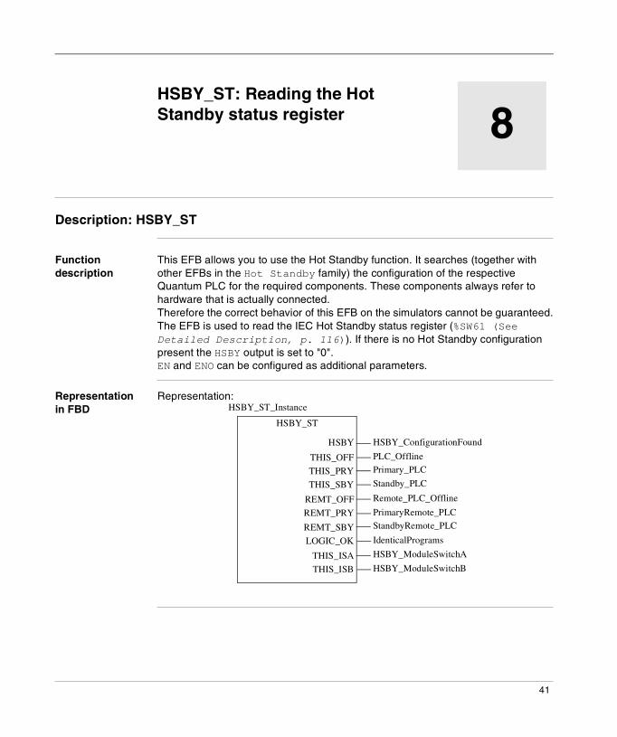
This EFB allows you to use the Hot Standby function. It searches (together with other EFBs in the Hot Standby family) the configuration of the respective Quantum PLC for the required components. These components always refer to hardware that is actually connected.Therefore the correct behavior of this EFB on the simulators cannot be guaranteed.The EFB is used to read the IEC Hot Standby status register (%SW61 (See Detailed Description, p. 116)). If there is no Hot Standby configuration present the HSBY output is set to "0".EN and ENO can be configured as additional parameters.
Representation in FBD
Representation:
HSBY_ConfigurationFound
HSBY_ST
PLC_OfflinePrimary_PLC
Standby_PLC
Remote_PLC_Offline
PrimaryRemote_PLCStandbyRemote_PLC
IdenticalPrograms
HSBY_ModuleSwitchA
HSBY_ModuleSwitchB
HSBY
THIS_OFF
THIS_PRY
THIS_SBY
REMT_OFF
REMT_PRY
REMT_SBY
LOGIC_OK
THIS_ISA
THIS_ISB
HSBY_ST_Instance
41
HSBY_ST
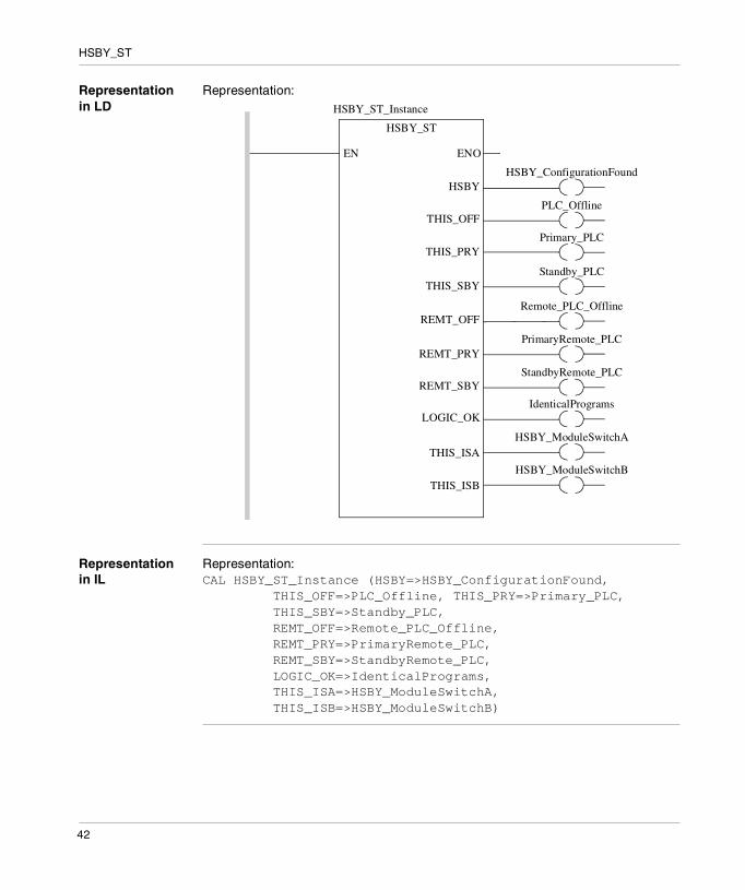
Representation in LD
Representation:
Representation in IL
Representation:CAL HSBY_ST_Instance (HSBY=>HSBY_ConfigurationFound, THIS_OFF=>PLC_Offline, THIS_PRY=>Primary_PLC, THIS_SBY=>Standby_PLC, REMT_OFF=>Remote_PLC_Offline, REMT_PRY=>PrimaryRemote_PLC, REMT_SBY=>StandbyRemote_PLC, LOGIC_OK=>IdenticalPrograms, THIS_ISA=>HSBY_ModuleSwitchA, THIS_ISB=>HSBY_ModuleSwitchB)
ENOEN
HSBY_ConfigurationFound
HSBY_ST
PLC_Offline
Primary_PLC
Standby_PLC
Remote_PLC_Offline
PrimaryRemote_PLC
StandbyRemote_PLC
IdenticalPrograms
HSBY_ModuleSwitchA
HSBY
THIS_OFF
THIS_PRY
THIS_SBY
REMT_OFF
REMT_PRY
REMT_SBY
LOGIC_OK
THIS_ISA
HSBY_ModuleSwitchBTHIS_ISB
HSBY_ST_Instance
42
HSBY_ST
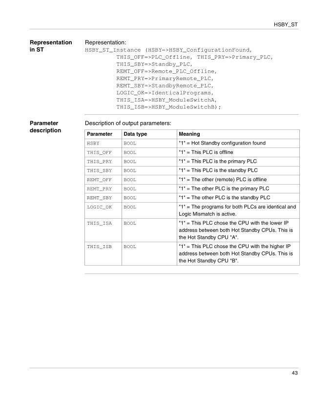
Representation in ST
Representation:HSBY_ST_Instance (HSBY=>HSBY_ConfigurationFound, THIS_OFF=>PLC_Offline, THIS_PRY=>Primary_PLC, THIS_SBY=>Standby_PLC, REMT_OFF=>Remote_PLC_Offline, REMT_PRY=>PrimaryRemote_PLC, REMT_SBY=>StandbyRemote_PLC, LOGIC_OK=>IdenticalPrograms, THIS_ISA=>HSBY_ModuleSwitchA, THIS_ISB=>HSBY_ModuleSwitchB);
Parameter description
Description of output parameters:
Parameter Data type Meaning
HSBY BOOL "1" = Hot Standby configuration found
THIS_OFF BOOL "1" = This PLC is offline
THIS_PRY BOOL "1" = This PLC is the primary PLC
THIS_SBY BOOL "1" = This PLC is the standby PLC
REMT_OFF BOOL "1" = The other (remote) PLC is offline
REMT_PRY BOOL "1" = The other PLC is the primary PLC
REMT_SBY BOOL "1" = The other PLC is the standby PLC
LOGIC_OK BOOL "1" = The programs for both PLCs are identical and Logic Mismatch is active.
THIS_ISA BOOL "1" = This PLC chose the CPU with the lower IP address between both Hot Standby CPUs. This is the Hot Standby CPU "A".
THIS_ISB BOOL "1" = This PLC chose the CPU with the higher IP address between both Hot Standby CPUs. This is the Hot Standby CPU "B".
43

HSBY_ST
44
9
HSBY_WR: Writing to the Hot Standby command registerDescription: HSBY_WR
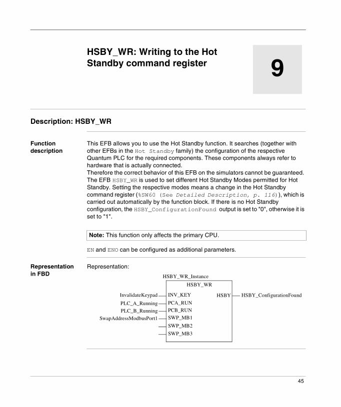
Function description
This EFB allows you to use the Hot Standby function. It searches (together with other EFBs in the Hot Standby family) the configuration of the respective Quantum PLC for the required components. These components always refer to hardware that is actually connected.Therefore the correct behavior of this EFB on the simulators cannot be guaranteed. The EFB HSBY_WR is used to set different Hot Standby Modes permitted for Hot Standby. Setting the respective modes means a change in the Hot Standby command register (%SW60 (See Detailed Description, p. 116)), which is carried out automatically by the function block. If there is no Hot Standby configuration, the HSBY_ConfigurationFound output is set to "0", otherwise it is set to "1".
EN and ENO can be configured as additional parameters.
Representation in FBD
Representation:
Note: This function only affects the primary CPU.
HSBY_ConfigurationFound
HSBY_WR
InvalidateKeypad
PLC_A_Running
PLC_B_Running
SwapAddressModbusPort1
HSBYINV_KEY
PCA_RUNPCB_RUN
SWP_MB1
SWP_MB2
SWP_MB3
HSBY_WR_Instance
45
HSBY_WR
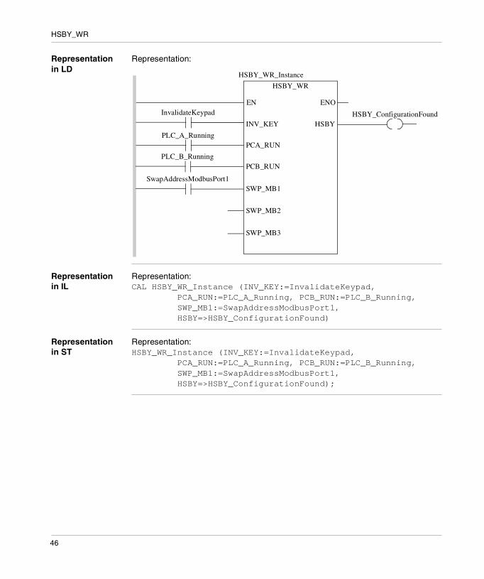
Representation in LD
Representation:
Representation in IL
Representation:CAL HSBY_WR_Instance (INV_KEY:=InvalidateKeypad, PCA_RUN:=PLC_A_Running, PCB_RUN:=PLC_B_Running, SWP_MB1:=SwapAddressModbusPort1, HSBY=>HSBY_ConfigurationFound)
Representation in ST
Representation:HSBY_WR_Instance (INV_KEY:=InvalidateKeypad, PCA_RUN:=PLC_A_Running, PCB_RUN:=PLC_B_Running, SWP_MB1:=SwapAddressModbusPort1, HSBY=>HSBY_ConfigurationFound);
ENOEN
HSBY_WR
HSBYINV_KEY
PCA_RUN
PCB_RUN
SWP_MB1
SWP_MB2
SWP_MB3
InvalidateKeypad
PLC_A_Running
PLC_B_Running
SwapAddressModbusPort1
HSBY_ConfigurationFound
HSBY_WR_Instance
46
HSBY_WR
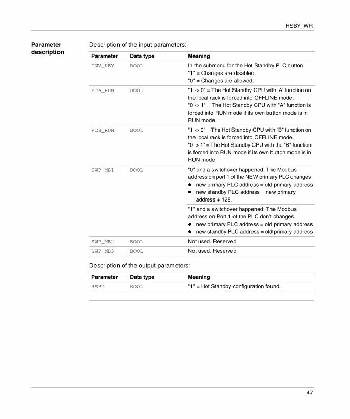
Parameter description
Description of the input parameters:
Description of the output parameters:
Parameter Data type Meaning
INV_KEY BOOL In the submenu for the Hot Standby PLC button"1" = Changes are disabled."0" = Changes are allowed.
PCA_RUN BOOL "1 -> 0" = The Hot Standby CPU with ‘A’ function on the local rack is forced into OFFLINE mode."0 -> 1" = The Hot Standby CPU with "A" function is forced into RUN mode if its own button mode is in RUN mode.
PCB_RUN BOOL "1 -> 0" = The Hot Standby CPU with "B" function on the local rack is forced into OFFLINE mode."0 -> 1" = The Hot Standby CPU with the "B" function is forced into RUN mode if its own button mode is in RUN mode.
SWP MB1 BOOL "0" and a switchover happened: The Modbus address on port 1 of the NEW primary PLC changes.� new primary PLC address = old primary address� new standby PLC address = new primary
address + 128.
"1" and a switchover happened: The Modbus address on Port 1 of the PLC don’t changes.� new primary PLC address = old primary address� new standby PLC address = old primary address
SWP_MB2 BOOL Not used. Reserved
SWP MB3 BOOL Not used. Reserved
Parameter Data type Meaning
HSBY BOOL "1" = Hot Standby configuration found.
47

HSBY_WR
48
10
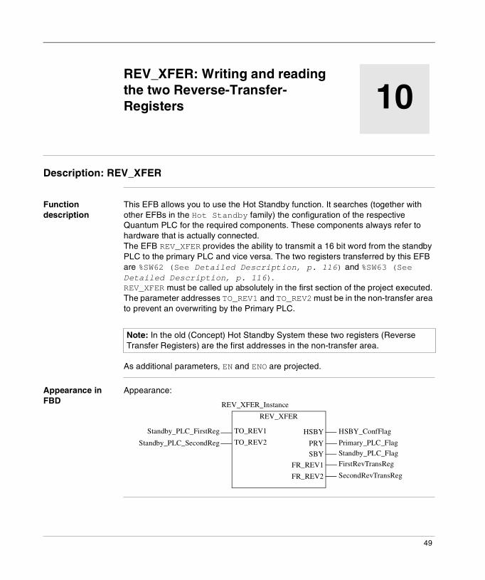
REV_XFER: Writing and reading the two Reverse-Transfer-RegistersDescription: REV_XFER
Function description
This EFB allows you to use the Hot Standby function. It searches (together with other EFBs in the Hot Standby family) the configuration of the respective Quantum PLC for the required components. These components always refer to hardware that is actually connected.The EFB REV_XFER provides the ability to transmit a 16 bit word from the standby PLC to the primary PLC and vice versa. The two registers transferred by this EFB are %SW62 (See Detailed Description, p. 116) and %SW63 (See Detailed Description, p. 116). REV_XFER must be called up absolutely in the first section of the project executed. The parameter addresses TO_REV1 and TO_REV2 must be in the non-transfer area to prevent an overwriting by the Primary PLC.
As additional parameters, EN and ENO are projected.
Appearance in FBD
Appearance:
Note: In the old (Concept) Hot Standby System these two registers (Reverse Transfer Registers) are the first addresses in the non-transfer area.
HSBY_ConfFlag
REV_XFER
Standby_PLC_FirstReg
Standby_PLC_SecondReg Primary_PLC_FlagStandby_PLC_Flag
FirstRevTransReg
SecondRevTransReg
HSBY
PRY
SBY
FR_REV1
FR_REV2
TO_REV1
TO_REV2
REV_XFER_Instance
49

REV_XFER
Appearance in LD
Appearance:
Appearance in IL Appearance:CAL REV_XFER_Instance (TO_REV1:=Standby_PLC_FirstReg, TO_REV2:=Standby_PLC_SecondReg, HSBY=>HSBY_ConfFlag, PRY=>Primary_PLC_Flag, SBY=>Standby_PLC_Flag, FR_REV1=>FirstRevTransReg, FR_REV2=>SecondtRevTransReg)
Appearance in ST
Appearance:REV_XFER_Instance (TO_REV1:=Standby_PLC_FirstReg, TO_REV2:=Standby_PLC_SecondReg, HSBY=>HSBY_ConfFlag, PRY=>Primary_PLC_Flag, SBY=>Standby_PLC_Flag, FR_REV1=>FirstRevTransReg, FR_REV2=>SecondtRevTransReg);
ENOEN
HSBY_ConfFlag
REV_XFER
Primary_PLC_Flag
Standby_PLC_Flag
HSBY
PRY
SBY
FR_REV1
FR_REV2
TO_REV1
TO_REV2Standby_PLC_SecondReg
Standby_PLC_FirstReg
FirstRevTransReg
SecondRevTransReg
REV_XFER_Instance
50

REV_XFER
Parameter description
Description of input parameters:
Description of the output parameters:
Parameter Data type Description
TO_REV1 INT Describes the first reverse transfer register if this PLC is the standby PLC.
TO_REV2 INT Describes the second reverse transfer register if this PLC is the standby PLC.
Parameter Data type Description
HSBY BOOL "1" = Hot Standby configuration
PRY BOOL 1 = This PLC is the primary PLC.
SBY BOOL 1 = This PLC is the standby PLC.
FR_REV1 INT Content of first reverse transfer register (%SW62 (See Detailed Description, p. 116)). Output only if HSBY is "1".
FR_REV2 INT Content of second reverse transfer register (%SW63 (See Detailed Description, p. 116)). Output only if HSBY is "1".
51

REV_XFER
52

IV
SFC ManagementIntroduction
Overview This section describes the elementary functions and elementary function blocks of the SFC Management family.
What's in this Part?
This part contains the following chapters:
Chapter Chapter Name Page
11 CLEARCHART: Reset all active steps 55
12 FREEZECHART: Freeze sequence 59
13 INITCHART: Reset all active steps and start sequence normally
63
14 RESETSTEP: Reset a specific step in the sequence 67
15 SETSTEP: Set a specific step in the sequence 69
16 SFCCNTRL: SFC Control 71
53

SFC Management
54
11
CLEARCHART: Reset all active stepsDescription
Function description
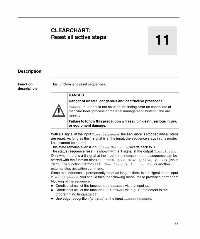
This function is to reset sequences.
With a 1 signal at the input ClearSequence, the sequence is stopped and all steps are reset. As long as the 1 signal is at the input, the sequence stays in this mode, i.e. it cannot be started.This state remains even if input ClearSequence reverts back to 0. The status (sequence reset) is shown with a 1 signal at the output ClearState. Only when there is a 0 signal at the input ClearSequence, the sequence can be started with the function block SFCCNTRL (See Description, p. 72) (Input INIT), the function INITCHART (See Description, p. 63) or another external step activation command.Since the sequence is permanently reset as long as there is a 1 signal at the input ClearSequence, you should take the following measures to prevent a permanent blocking of the sequence:� Conditional call of the function CLEARCHART via the input EN.� Conditional call of the function CLEARCHART via e.g. IF statement in the
programming language ST.� Use edge recognition (R_TRIG) at the input ClearSequence.
DANGER
Danger of unsafe, dangerous and destructive processes.
CLEARCHART should not be used for finding error on controllers of machine tools, process or material management system if the are running.
Failure to follow this precaution will result in death, serious injury, or equipment damage.
55
CLEARCHART
EN and ENO can be configured as additional parameters.
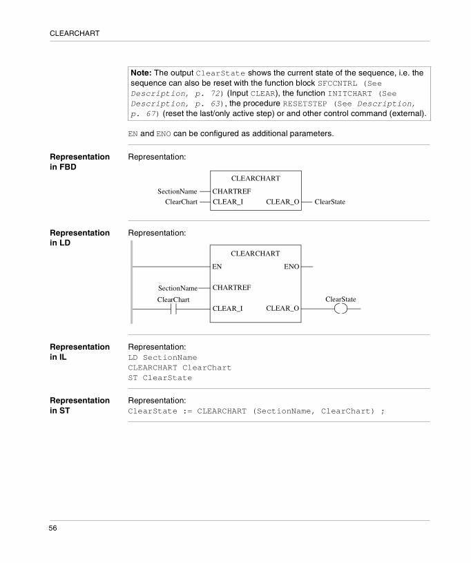
Representation in FBD
Representation:
Representation in LD
Representation:
Representation in IL
Representation:LD SectionNameCLEARCHART ClearChartST ClearState
Representation in ST
Representation:ClearState := CLEARCHART (SectionName, ClearChart) ;
Note: The output ClearState shows the current state of the sequence, i.e. the sequence can also be reset with the function block SFCCNTRL (See Description, p. 72) (Input CLEAR), the function INITCHART (See Description, p. 63), the procedure RESETSTEP (See Description, p. 67) (reset the last/only active step) or and other control command (external).
CLEARCHART
CHARTREFSectionName
CLEAR_IClearChart ClearStateCLEAR_O
CLEARCHART
ENOEN
SectionName
ClearChart
CHARTREF
CLEAR_IClearState
CLEAR_O
56

CLEARCHART
Parameter description
Description of input parameters:
Description of output parameters:
Parameter Data type Description
CHARTREF SFCCHART_STATE Association with the SFC section to be controlled is done via the name of the section.If an SFC section is created then it is automatically assigned with a variable of data type SFCCHART_STATE. The variable that is created always has the name of the respective SFC section.)
CLEAR_I BOOL 0->1: Reset all active steps in the sequence.
Parameter Data type Description
CLEAR_O BOOL 1: Sequence was reset, i.e. the sequence has no active step
57

CLEARCHART
58
12
FREEZECHART: Freeze sequenceDescription
Function description
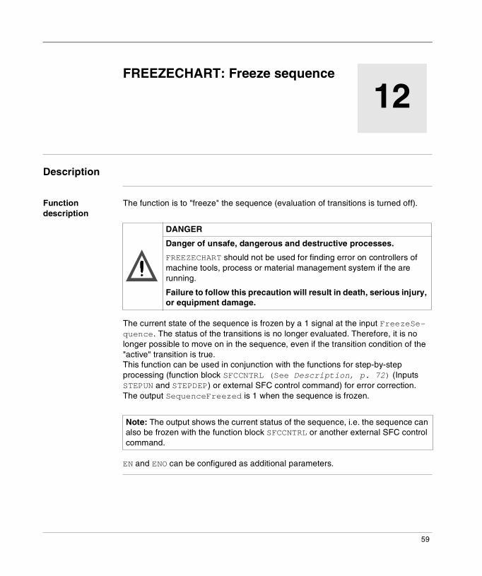
The function is to "freeze" the sequence (evaluation of transitions is turned off).
The current state of the sequence is frozen by a 1 signal at the input FreezeSe-quence. The status of the transitions is no longer evaluated. Therefore, it is no longer possible to move on in the sequence, even if the transition condition of the "active" transition is true. This function can be used in conjunction with the functions for step-by-step processing (function block SFCCNTRL (See Description, p. 72) (Inputs STEPUN and STEPDEP) or external SFC control command) for error correction.The output SequenceFreezed is 1 when the sequence is frozen.
EN and ENO can be configured as additional parameters.
DANGER
Danger of unsafe, dangerous and destructive processes.
FREEZECHART should not be used for finding error on controllers of machine tools, process or material management system if the are running.
Failure to follow this precaution will result in death, serious injury, or equipment damage.
Note: The output shows the current status of the sequence, i.e. the sequence can also be frozen with the function block SFCCNTRL or another external SFC control command.
59
FREEZECHART
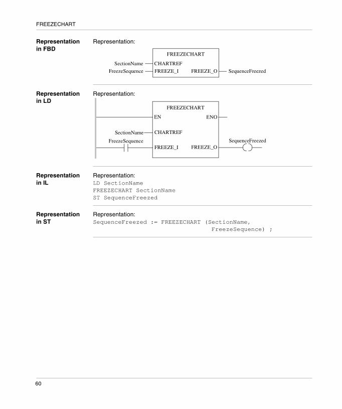
Representation in FBD
Representation:
Representation in LD
Representation:
Representation in IL
Representation:LD SectionNameFREEZECHART SectionNameST SequenceFreezed
Representation in ST
Representation:SequenceFreezed := FREEZECHART (SectionName, FreezeSequence) ;
FREEZECHART
CHARTREFSectionName
FREEZE_IFreezeSequence SequenceFreezedFREEZE_O
FREEZECHART
ENOEN
SectionName
FreezeSequence
CHARTREF
FREEZE_ISequenceFreezed
FREEZE_O
60
FREEZECHART
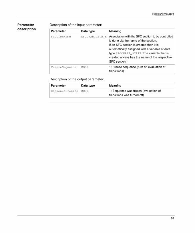
Parameter description
Description of the input parameter:
Description of the output parameter:
Parameter Data type Meaning
SectionName SFCCHART_STATE Association with the SFC section to be controlled is done via the name of the section.If an SFC section is created then it is automatically assigned with a variable of data type SFCCHART_STATE. The variable that is created always has the name of the respective SFC section.)
FreezeSequence BOOL 1: Freeze sequence (turn off evaluation of transitions)
Parameter Data type Meaning
SequenceFreezed BOOL 1: Sequence was frozen (evaluation of transitions was turned off)
61

FREEZECHART
62

13
INITCHART: Reset all active steps and start sequence normallyDescription
Function description
This function is to reset and normally start sequences.
In relation to all functions and function blocks for sequence control, INITCHART has the highest priority.� Reset sequence
With a 1 signal at the input InitSequence, the sequence is stopped and all steps are reset. As long as the 1 signal is at the input, the sequence stays in this mode, i.e. it cannot be started.Since the sequence is permanently reset as long as there is a 1 signal at the input InitSequence, you should take the following measures to prevent a permanent blocking of the sequence:� Conditional call of the function INITCHART via the input EN.� Conditional call of the function INITCHART via e.g. IF statement in the
programming language ST.� Use edge recognition (R_TRIG) at the input InitSequence.
� Start sequence normallyWith a 1->0 edge at the input InitSequence, the sequence is started normally, i.e. the initial step is activated. This is shown for one cycle with a 1 signal at the output InitState.
DANGER
Danger of unsafe, dangerous and destructive processes.
INITCHART should not be used for finding error on controllers of machine tools, process or material management system if the are running.
Failure to follow this precaution will result in death, serious injury, or equipment damage.
63

INITCHART
EN and ENO can be configured as additional parameters.
Representation in FBD
Representation:
Representation in LD
Representation:
Representation in IL
Representation:LD SectionNameINITCHART InitializeChartST InitState
Representation in ST
Representation:InitState := INITCHART (SectionName, InitializeChart) ;
Note: The output InitState shows the current status of the sequence, i.e. the sequence can also be normally started with the function block SFCCNTRL (See Description, p. 72) (input INIT) or another external control command.
INITCHART
CHARTREFSectionName
INIT_IInitializeChart InitStateINIT_O
INITCHART
ENOEN
SectionName
InitializeChart
CHARTREF
INIT_IInitState
INIT_O
64
INITCHART
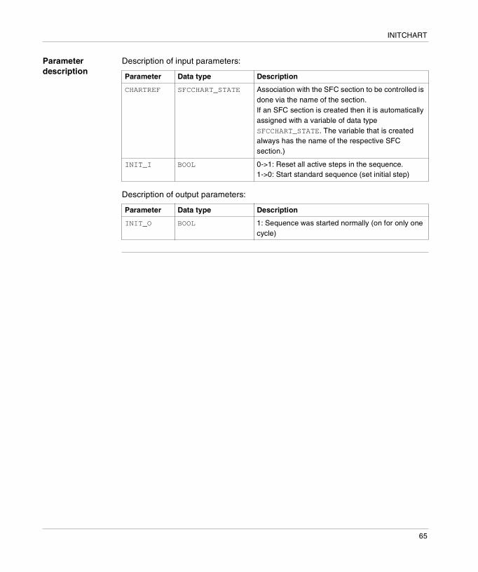
Parameter description
Description of input parameters:
Description of output parameters:
Parameter Data type Description
CHARTREF SFCCHART_STATE Association with the SFC section to be controlled is done via the name of the section.If an SFC section is created then it is automatically assigned with a variable of data type SFCCHART_STATE. The variable that is created always has the name of the respective SFC section.)
INIT_I BOOL 0->1: Reset all active steps in the sequence.1->0: Start standard sequence (set initial step)
Parameter Data type Description
INIT_O BOOL 1: Sequence was started normally (on for only one cycle)
65

INITCHART
66

14
RESETSTEP: Reset a specific step in the sequenceDescription
Function description
This procedure is to reset a step in a sequence.
This procedure resets the specific step.Since the step stays reset as long as this procedure is running (the procedure is run cyclically), you should take the following measures to prevent a permanent blocking of the sequence:� Conditional call of the procedure RESETSTEP via the input EN.� Conditional call of the procedure RESETSTEP via e.g. IF statement in the
programming language ST.� Use edge recognition (R_TRIG) at the input.When the last/only active step of the sequence is reset, the sequence can only be restarted with the function block SFCCNTRL (See Description, p. 72) (input INIT), the function INITCHART (See Description, p. 63) or the procedure SETSTEP (See Description, p. 69) or another external step activation command.
EN and ENO can be configured as additional parameters.
Note: The procedure can only be used in the operation mode "Multi-Token".
DANGER
Danger of unsafe, dangerous and destructive processes.
RESETSTEP should not be used for finding error on controllers of machine tools, process or material management system if the are running.
Failure to follow this precaution will result in death, serious injury, or equipment damage.
67

RESETSTEP
Representation in FBD
Representation:
Representation in LD
Representation:
Representation in IL
Representation:LD StepNameRESETSTEP
Representation in ST
Representation:RESETSTEP (StepName);
Parameter description
Description of the input parameter:
RESETSTEP
STEPNAMEStepName
RESETSTEP
ENOEN
StepName STEPNAME
Parameter Data type Meaning
StepName SFCSTEP_STATE Assignment of the step to be reset via the name of the step.(If an SFC step is created then it is automatically assigned with a variable of data type SFCSTEP_STATE. The variable that is created always has the name of the respective SFC step. )
68

15
SETSTEP: Set a specific step in the sequenceDescription
Function description
This procedure is to set a step in a sequence.
This procedure sets the specific step, in addition to the already active step(s). Already active steps are not affected by this procedure.Since the step stays set as long as this procedure is running (the procedure is run cyclically), you should take the following measures to prevent a permanent setting of the sequence:� Conditional call of the procedure SETSTEP via the input EN.� Conditional call of the procedure SETSTEP via e.g. IF statement in the
programming language ST.� Use edge recognition (R_TRIG) at the input.
EN and ENO can be configured as additional parameters.
Note: The procedure can only be used in the operation mode "Multi-Token".
DANGER
Danger of unsafe, dangerous and destructive processes.
SETSTEP should not be used for finding error on controllers of machine tools, process or material management system if the are running.
Failure to follow this precaution will result in death, serious injury, or equipment damage.
69

SETSTEP
Representation in FBD
Representation:
Representation in LD
Representation:
Representation in IL
Representation:LD StepNameSETSTEP
Representation in ST
Representation:SETSTEP (StepName);
Parameter description
Description of the input parameter:
SETSTEP
STEPNAMEStepName
SETSTEP
ENOEN
StepName STEPNAME
Parameter Data type Meaning
StepName SFCSTEP_STATE Assignment of the step to be set via the name of the step.(If an SFC step is created then it is automatically assigned with a variable of data type SFCSTEP_STATE. The variable that is created always has the name of the respective SFC step. )
70
16
SFCCNTRL: SFC ControlOverview
Introduction This chapter describes the SFCCNTRL block.
What's in this Chapter?
This chapter contains the following topics:
Topic Page
Description 72
Parameter description 77
71

SFCCNTRL
Description
Function description
This function block is to control the execution sequences.For example, you can go through step by step, processing transition conditions can be turned on or off or the sequence can be reset to its initialization state.
EN and ENO can be configured as additional parameters.
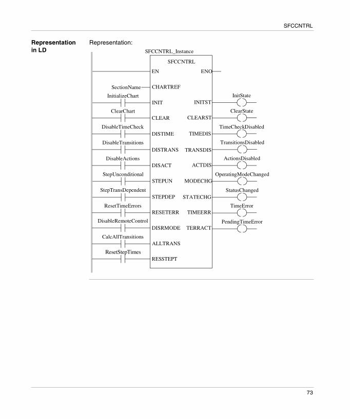
Representation in FBD
Representation:
DANGER
Danger of unsafe, dangerous and destructive processes.
INIT, CLEAR, DISTRANS, DISACT, STEPUN and STEPDEP should not be used for finding errors when controlling machine tools, processes or material management systems, if they are running.
Failure to follow this precaution will result in death, serious injury, or equipment damage.
SFCCNTRL
ClearStateCLEARST
TimeCheckDisabledTIMEDIS
TransitionsDisabledTRANSDIS
CHARTREFSectionName
INITInitializeChart
CLEARClearChart
DISTIMEDisableTimeCheck
DISTRANSDisableTransitions
DISACTDisableActions
SFCCNTRL_Instance
InitStateINITST
ActionsDisabledACTDIS
STEPUNStepUnconditional
STEPDEPStepTransDependent
RESETERRResetTimeErrors
DISRMODEDisableRemoteControl
OperatingModeChangedMODECHG
StatusChangedSTATECHG
TimeErrorTIMEERRPendingTimeErrorTERRACT
ALLTRANSCalcAllTransitions
RESSTEPTResetStepTimes
72
SFCCNTRL
Representation in LD
Representation:
SFCCNTRL
ENOEN
SFCCNTRL_Instance
SectionName
InitializeChart
ClearChart ClearState
DisableTimeCheck TimeCheckDisabled
DisableTransitions TransitionsDisabled
DisableActions
CHARTREF
INIT
CLEAR
DISTIME
DISTRANS
DISACT
CLEARST
TIMEDIS
TRANSDIS
InitStateINITST
ActionsDisabledACTDIS
StepUnconditionalSTEPUN
StepTransDependent
ResetTimeErrors
DisableRemoteControl
STEPDEP
RESETERR
DISRMODE
OperatingModeChanged
StatusChanged
TimeError
MODECHG
STATECHG
TIMEERR
PendingTimeErrorTERRACT
CalcAllTransitions
ResetStepTimes
ALLTRANS
RESSTEPT
73

SFCCNTRL
Representation in IL
Representation:CAL SFCCNTRL_Instance (CHARTREF:=SectionName, INIT:=InitializeChart, CLEAR:=ClearChart, DISTIME:=DisableTimeCheck, DISTRANS:=DisableTransitions, DISACT:=DisableActions, STEPUN:=StepUnconditional, STEPDEP:=StepTransDependent, RESETERR:=ResetTimeErrors, DISRMODE:=DisableRemoteControl, ALLTRANS:=CalcAllTransitions, RESSTEPT:=ResetStepTimes, INITST=>InitState, CLEARST=>ClearState, TIMEDIS=>TimeCheckDisabled, TRANSDIS=>TransitionsDisabled, ACTDIS=>ActionsDisabled, MODECHG=>OperatingModeChanged, STATECHG=>StatusChanged, TIMEERR=>TimeError, TERRACT=>PendingTimeError)
Representation in ST
Representation:SFCCNTRL_Instance (CHARTREF:=SectionName, INIT:=InitializeChart, CLEAR:=ClearChart, DISTIME:=DisableTimeCheck, DISTRANS:=DisableTransitions, DISACT:=DisableActions, STEPUN:=StepUnconditional, STEPDEP:=StepTransDependent, RESETERR:=ResetTimeErrors, DISRMODE:=DisableRemoteControl, ALLTRANS:=CalcAllTransitions, RESSTEPT:=ResetStepTimes, INITST=>InitState, CLEARST=>ClearState, TIMEDIS=>TimeCheckDisabled, TRANSDIS=>TransitionsDisabled, ACTDIS=>ActionsDisabled, MODECHG=>OperatingModeChanged, STATECHG=>StatusChanged, TIMEERR=>TimeError, TERRACT=>PendingTimeError) ;
74

SFCCNTRL
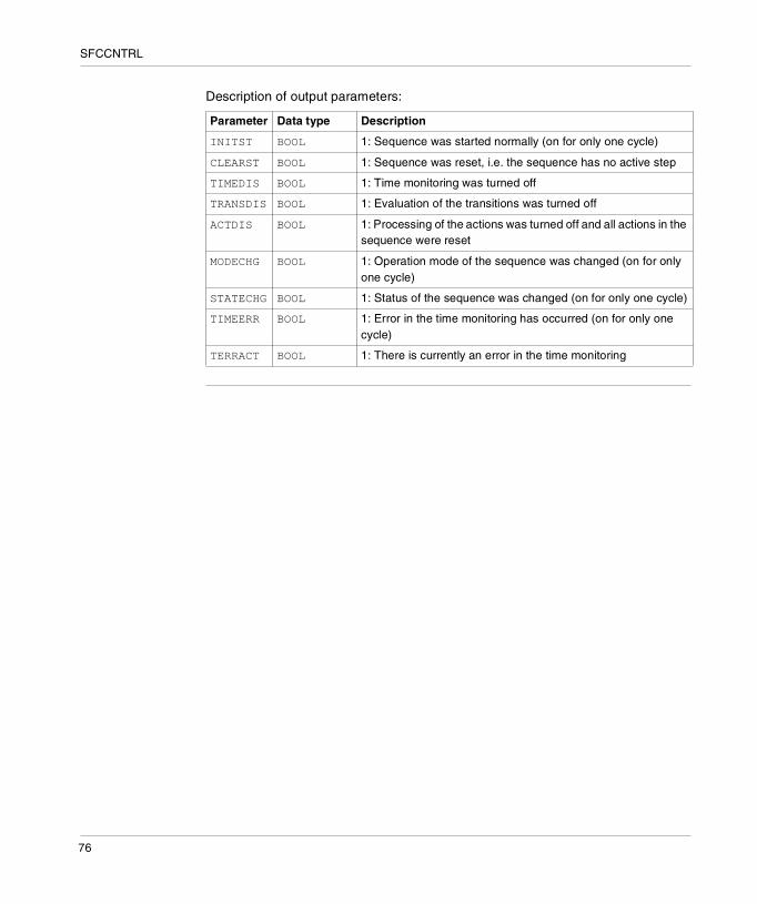
Parameter description
Description of input parameters:
Parameter Data type Description
CHARTREF SFCCHART_STATE
Association with the SFC section to be controlled is done via the name of the sectionIf an SFC section is created then it is automatically assigned with a variable of data type SFCCHART_STATE. The variable that is created always has the name of the respective SFC section.)
INIT BOOL 0->1: Reset all active steps in the sequence.1->0: Start standard sequence (set initial step)
CLEAR BOOL 0->1: Reset all active steps in the sequence.
DISTIME BOOL 1: Turn off time monitoring
DISTRANS BOOL 1: Turn of evaluation of the transitions (freeze sequence)
DISACT BOOL 1: Turn off processing of the actions and reset all actions in the sequence
STEPUN BOOL 0->1: Activate the next step, independent of the transition condition
STEPDEP BOOL 0->1: Activate the next step, dependent on the transition condition
RESETERR BOOL 0->1: Reset the time monitoring error.
DISRMOTE BOOL 1: Prevent control of the sequence using processing parameters of the Online Animation Panel
ALLTRANS BOOL 1: Calculate all transition sections
RESSTEPT BOOL 0->1: Deactivate and reset time calculation1->0: Restart time calculation
75
SFCCNTRL
Description of output parameters:
Parameter Data type Description
INITST BOOL 1: Sequence was started normally (on for only one cycle)
CLEARST BOOL 1: Sequence was reset, i.e. the sequence has no active step
TIMEDIS BOOL 1: Time monitoring was turned off
TRANSDIS BOOL 1: Evaluation of the transitions was turned off
ACTDIS BOOL 1: Processing of the actions was turned off and all actions in the sequence were reset
MODECHG BOOL 1: Operation mode of the sequence was changed (on for only one cycle)
STATECHG BOOL 1: Status of the sequence was changed (on for only one cycle)
TIMEERR BOOL 1: Error in the time monitoring has occurred (on for only one cycle)
TERRACT BOOL 1: There is currently an error in the time monitoring
76

SFCCNTRL
Parameter description
General
CHARTREF Association with the SFC to be controlled.If an SFC section is created then it is automatically assigned with a variable of data type SFCCHART_STATE. The variable that is created always has the name of the respective SFC section. This variable is used for assigning the function block SFCCNTRL to the SFC section to be controlled.
DANGER
Danger of unsafe, dangerous and destructive processes.
INIT, CLEAR, DISTRANS, DISACT, STEPUN and STEPDEP should not be used for finding errors when controlling machine tools, processes or material management systems, if they are running.
Failure to follow this precaution will result in death, serious injury, or equipment damage.
77
SFCCNTRL
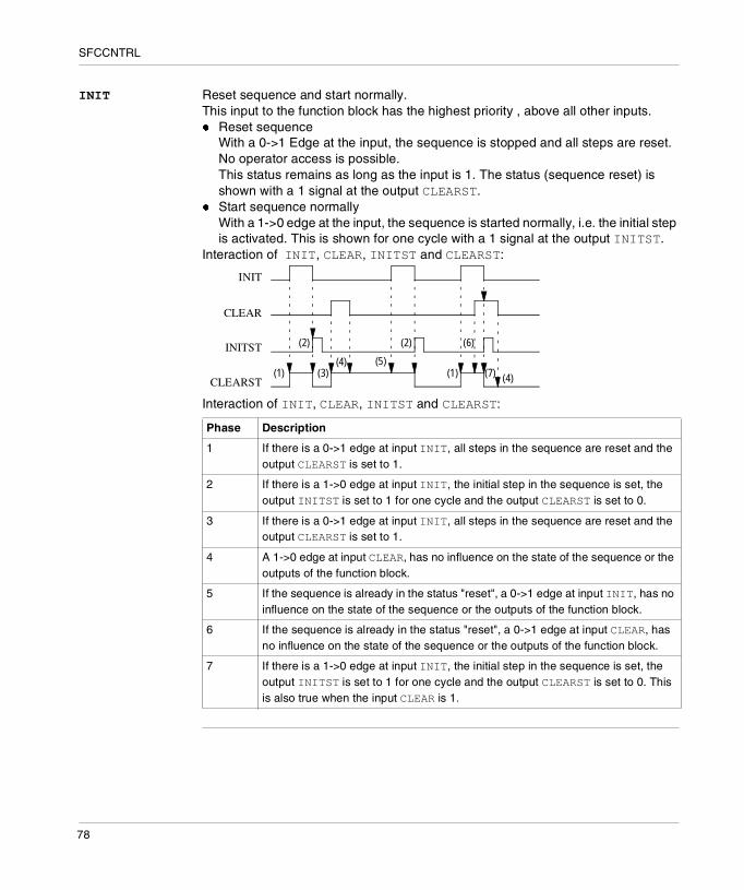
INIT Reset sequence and start normally.This input to the function block has the highest priority , above all other inputs.� Reset sequence
With a 0->1 Edge at the input, the sequence is stopped and all steps are reset. No operator access is possible.This status remains as long as the input is 1. The status (sequence reset) is shown with a 1 signal at the output CLEARST.
� Start sequence normallyWith a 1->0 edge at the input, the sequence is started normally, i.e. the initial step is activated. This is shown for one cycle with a 1 signal at the output INITST.
Interaction of INIT, CLEAR, INITST and CLEARST:
Interaction of INIT, CLEAR, INITST and CLEARST:
Phase Description
1 If there is a 0->1 edge at input INIT, all steps in the sequence are reset and the output CLEARST is set to 1.
2 If there is a 1->0 edge at input INIT, the initial step in the sequence is set, the output INITST is set to 1 for one cycle and the output CLEARST is set to 0.
3 If there is a 0->1 edge at input INIT, all steps in the sequence are reset and the output CLEARST is set to 1.
4 A 1->0 edge at input CLEAR, has no influence on the state of the sequence or the outputs of the function block.
5 If the sequence is already in the status "reset", a 0->1 edge at input INIT, has no influence on the state of the sequence or the outputs of the function block.
6 If the sequence is already in the status "reset", a 0->1 edge at input CLEAR, has no influence on the state of the sequence or the outputs of the function block.
7 If there is a 1->0 edge at input INIT, the initial step in the sequence is set, the output INITST is set to 1 for one cycle and the output CLEARST is set to 0. This is also true when the input CLEAR is 1.
INIT
CLEAR
INITST
CLEARST
(2)
(4)(1) (1)
(2)
(3)(5)
(7) (4)
(6)
78
SFCCNTRL
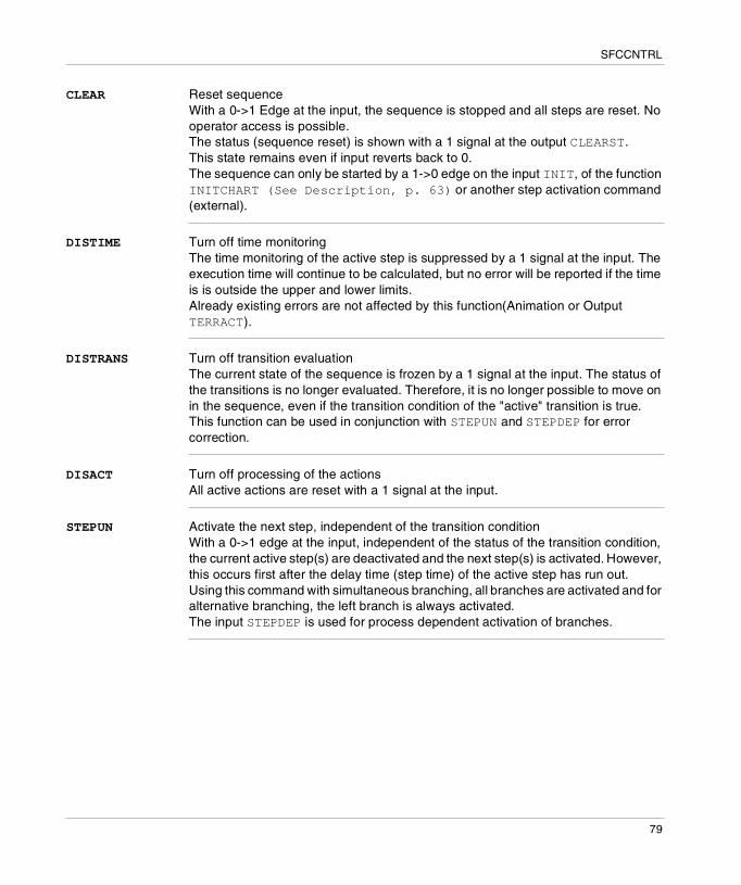
CLEAR Reset sequenceWith a 0->1 Edge at the input, the sequence is stopped and all steps are reset. No operator access is possible.The status (sequence reset) is shown with a 1 signal at the output CLEARST. This state remains even if input reverts back to 0. The sequence can only be started by a 1->0 edge on the input INIT, of the function INITCHART (See Description, p. 63) or another step activation command (external).
DISTIME Turn off time monitoringThe time monitoring of the active step is suppressed by a 1 signal at the input. The execution time will continue to be calculated, but no error will be reported if the time is is outside the upper and lower limits.Already existing errors are not affected by this function(Animation or Output TERRACT).
DISTRANS Turn off transition evaluationThe current state of the sequence is frozen by a 1 signal at the input. The status of the transitions is no longer evaluated. Therefore, it is no longer possible to move on in the sequence, even if the transition condition of the "active" transition is true. This function can be used in conjunction with STEPUN and STEPDEP for error correction.
DISACT Turn off processing of the actionsAll active actions are reset with a 1 signal at the input.
STEPUN Activate the next step, independent of the transition conditionWith a 0->1 edge at the input, independent of the status of the transition condition, the current active step(s) are deactivated and the next step(s) is activated. However, this occurs first after the delay time (step time) of the active step has run out.Using this command with simultaneous branching, all branches are activated and for alternative branching, the left branch is always activated.The input STEPDEP is used for process dependent activation of branches.
79
SFCCNTRL
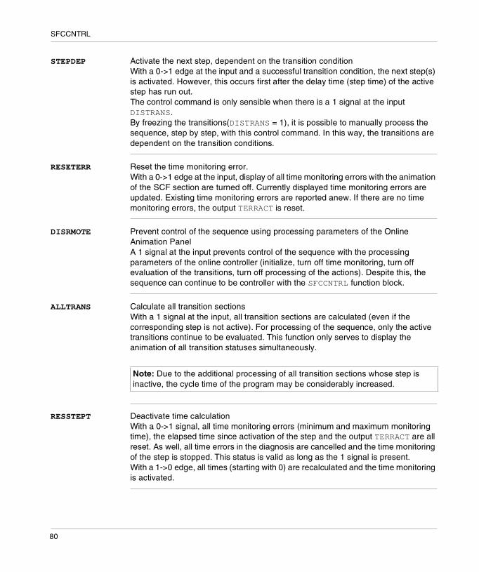
STEPDEP Activate the next step, dependent on the transition conditionWith a 0->1 edge at the input and a successful transition condition, the next step(s) is activated. However, this occurs first after the delay time (step time) of the active step has run out.The control command is only sensible when there is a 1 signal at the input DISTRANS.By freezing the transitions(DISTRANS = 1), it is possible to manually process the sequence, step by step, with this control command. In this way, the transitions are dependent on the transition conditions.
RESETERR Reset the time monitoring error.With a 0->1 edge at the input, display of all time monitoring errors with the animation of the SCF section are turned off. Currently displayed time monitoring errors are updated. Existing time monitoring errors are reported anew. If there are no time monitoring errors, the output TERRACT is reset.
DISRMOTE Prevent control of the sequence using processing parameters of the Online Animation PanelA 1 signal at the input prevents control of the sequence with the processing parameters of the online controller (initialize, turn off time monitoring, turn off evaluation of the transitions, turn off processing of the actions). Despite this, the sequence can continue to be controller with the SFCCNTRL function block.
ALLTRANS Calculate all transition sectionsWith a 1 signal at the input, all transition sections are calculated (even if the corresponding step is not active). For processing of the sequence, only the active transitions continue to be evaluated. This function only serves to display the animation of all transition statuses simultaneously.
RESSTEPT Deactivate time calculationWith a 0->1 signal, all time monitoring errors (minimum and maximum monitoring time), the elapsed time since activation of the step and the output TERRACT are all reset. As well, all time errors in the diagnosis are cancelled and the time monitoring of the step is stopped. This status is valid as long as the 1 signal is present. With a 1->0 edge, all times (starting with 0) are recalculated and the time monitoring is activated.
Note: Due to the additional processing of all transition sections whose step is inactive, the cycle time of the program may be considerably increased.
80

SFCCNTRL
INITST Sequence started normallyWith a 1->0 edge at the input INIT, the sequence is started normally, i.e. the initial step is activated. This is shown for one cycle with a 1 signal at the output INITST.see also INIT, p. 78
CLEARST Sequence was resetWith a 0->1 Edge at the input INIT or CLEAR , the sequence is stopped and all steps are reset.This state is maintained until a 1->0 edge at the input INIT occurs.see also INIT, p. 78
TIMEDIS Time monitoring was turned offThe output is 1 if the display of the time error was turned off, independent of if the display was turned off with the function block itself (input DISTIME) or via SFC control commands.
TRANSDIS Evaluation of the transitions was turned offThe output is 1 if the evaluation of the transitions was stopped.
ACTDIS Processing of the actions was turned off and all actions in the sequence were resetThe output is 1 if the display of the actions was stopped, independent of if the display was stopped with the function block itself (input DISACT) or via SFC control commands.
Note: The output shows the current status of the sequence, i.e. the sequence can also be normally started with the function INITCHART (See Description, p. 63) or another external control command.
Note: The output shows the current status of the sequence, i.e. the sequence can also be reset with the function INITCHART (See Description, p. 63), CLEARCHART (See Description, p. 55) or RESETSTEP (See Description, p. 67) (reset the last/only active step) or another external control command.
Note: The output shows the current status of the sequence, i.e. the sequence can also be frozen with the function FREEZECHART (See Description, p. 59) or another external SFC control command.
81
SFCCNTRL
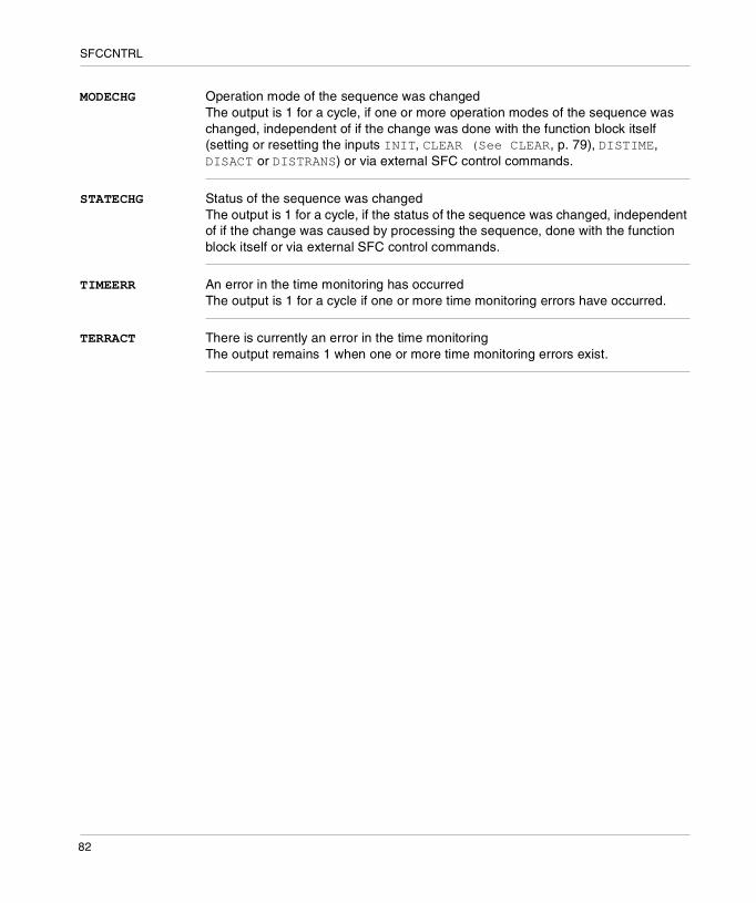
MODECHG Operation mode of the sequence was changedThe output is 1 for a cycle, if one or more operation modes of the sequence was changed, independent of if the change was done with the function block itself (setting or resetting the inputs INIT, CLEAR (See CLEAR, p. 79), DISTIME, DISACT or DISTRANS) or via external SFC control commands.
STATECHG Status of the sequence was changedThe output is 1 for a cycle, if the status of the sequence was changed, independent of if the change was caused by processing the sequence, done with the function block itself or via external SFC control commands.
TIMEERR An error in the time monitoring has occurredThe output is 1 for a cycle if one or more time monitoring errors have occurred.
TERRACT There is currently an error in the time monitoringThe output remains 1 when one or more time monitoring errors exist.
82

V
SysClockIntroduction
Overview This section describes the elementary functions and elementary function blocks of the SysClock family.
What's in this Part?
This part contains the following chapters:
Chapter Chapter Name Page
17 FREERUN: Free-running timer 85
18 PTC: Reading the stop date and code 87
19 RRTC_DT: Reading the system date 89
20 R_NTPC: Network real-time clock function 91
21 SCHEDULE: Real-time clock function 95
22 WRTC_DT: Updating the system date 99
83

SysClock
84
17
FREERUN: Free-running timerDescription
Function description
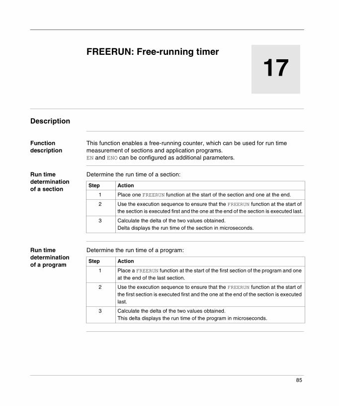
This function enables a free-running counter, which can be used for run time measurement of sections and application programs.EN and ENO can be configured as additional parameters.
Run time determination of a section
Determine the run time of a section:
Run time determination of a program
Determine the run time of a program:
Step Action
1 Place one FREERUN function at the start of the section and one at the end.
2 Use the execution sequence to ensure that the FREERUN function at the start of the section is executed first and the one at the end of the section is executed last.
3 Calculate the delta of the two values obtained.Delta displays the run time of the section in microseconds.
Step Action
1 Place a FREERUN function at the start of the first section of the program and one at the end of the last section.
2 Use the execution sequence to ensure that the FREERUN function at the start of the first section is executed first and the one at the end of the section is executed last.
3 Calculate the delta of the two values obtained.This delta displays the run time of the program in microseconds.
85
FREERUN
Representation in FBD
Representation:
Representation in LD
Representation:
Representation in IL
Representation:FREERUNST MeasuredTime
Representation in ST
Representation:MeasuredTime := FREERUN () ;
Parameter description
Description of the output parameter:
MeasuredTime
FREERUN
OUT
ENOEN
FREERUN
MeasuredTimeOUT
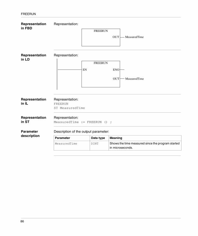
Parameter Data type Meaning
MeasuredTime DINT Shows the time measured since the program started in microseconds.
86

18
PTC: Reading the stop date and codeDescription
Description of the function
The PTC function reads the date and code of the most recent PLC stop, and saves the information in an integer table.
The additional parameters EN and ENO can be configured.
FBD representation
Representation:
LD representation
Representation:
IL representation Representation:PTCST Stop_Date
ST representation
Representation:PTC (Stop_Date);
PTC
Stop_DateENOEN
OUT
PTC
ENOEN
Stop_DateOUT
87

PTC
Description of the parameters
The following table describes the output parameters:
Parameter Type Comment
Stop_Date ARRAY [0..4] OF INT
Table of 5 integers containing the date in the first four words (equivalent of %SW54 to %SW57) and the error code in the last word. The error code is the one indicated in the %SW58 system word:� 1 = switch from RUN to STOP by the terminal,� 2 = stop on software fault (PLC task overflow),� 4 = mains power cut,� 5 = stop on hardware fault,� 6 = stop on HALT instruction.
Example: Stop at 22:53:10 on January 8, 2001. The contents of Stop_Date were as follows:Stop_Date[0]=16#0010
Stop_Date[1]=16#2253
Stop_Date[2]=16#0108
Stop_Date[3]=16#2001
88

19
RRTC_DT: Reading the system dateDescription
Description of the function
The RRTC_DT function captures the current date from the PLC's real-time clock.
The additional parameters EN and ENO can be configured.
FBD representation
Representation:
LD representation
Representation:
IL representation Representation:RRTC_DTST Result_Date
ST representation
Representation:RRTC_DT(Result_Date);
ENOEN
RRTC_DT
Result_DateOUT
ENOEN
Result_Date
RRTC_DT
OUT
89

RRTC_DT
Description of the parameters
The following table describes the output parameters:
Parameter Type Comment
Result_Date DT Result_Date contains the current date value in DT format.
90
20
R_NTPC: Network real-time clock functionDescription
Description of the Function
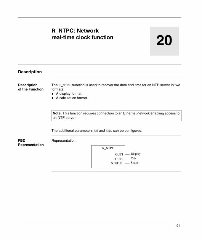
The R_NTPC function is used to recover the date and time for an NTP server in two formats:� A display format.� A calculation format.
The additional parameters EN and ENO can be configured.
FBD Representation
Representation:
Note: This function requires connection to an Ethernet network enabling access to an NTP server.
R_NTPC
DisplayOUT1CalcOUT2StatusSTATUS
91
R_NTPC
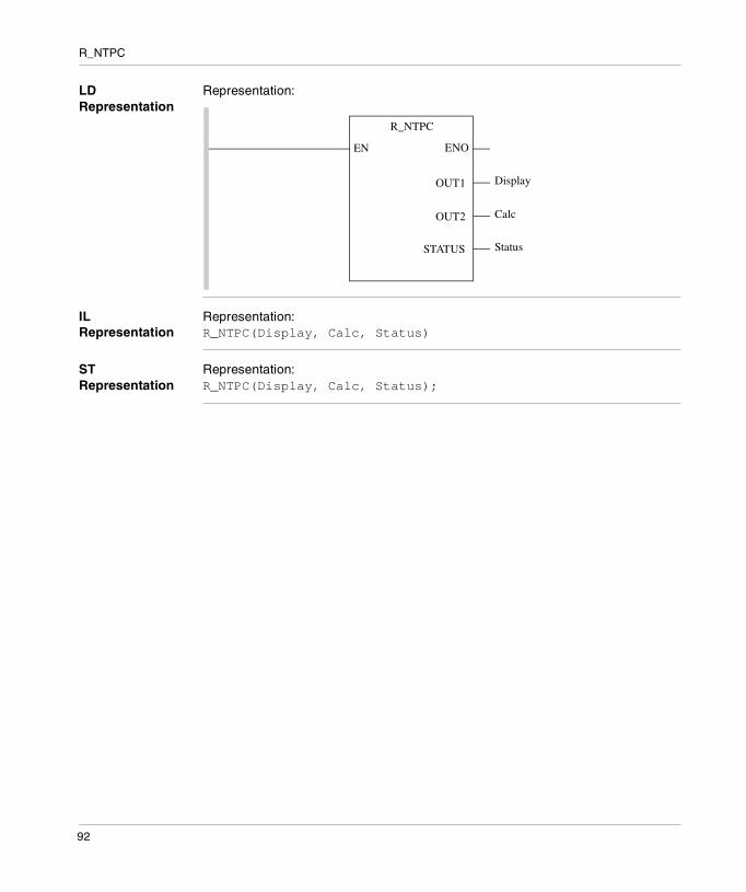
LD Representation
Representation:
IL Representation
Representation:R_NTPC(Display, Calc, Status)
ST Representation
Representation:R_NTPC(Display, Calc, Status);
R_NTPC
ENOEN
DisplayOUT1
CalcOUT2
StatusSTATUS
92

R_NTPC
Description of the Parameters
The following table describes the output parameters:
Parameter Type Comment
Display Display_NTPC The Display output contains the date and time acquired on an NTP server. The Display_NTPC type is a predefined structure comprising a DT type element and an INT type element. This gives us:� Display.DT_value containing the date, � Display.Milisecond containing the number of
milliseconds of this date, as the second is the minimum measurement unit for the DT format.
Calc Calc_NTPC The Calc output contains the date and time acquired on an NTP server (as in a Display variable, only with a different format). The Calc_NTPC type is a predefined structure comprising a UDINT type element and an INT type element. This gives us:� Calc.Seconds containing the number of seconds
passed since January 1, 1900, at 00:00. � Calc.Fraction_Second containing the number of
milliseconds to add for the precision of the result to be around a millisecond.
Status INT The Status variable indicates the validity of the R_NTPC function result. Status is:� 0 if the result is not valid, � 1 if the result is valid, and if the precision of the result
is less than 10 ms.
93

R_NTPC
94
21
SCHEDULE: Real-time clock functionDescription
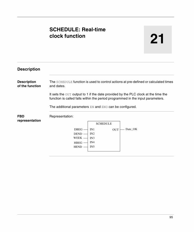
Description of the function
The SCHEDULE function is used to control actions at pre-defined or calculated times and dates.
It sets the OUT output to 1 if the date provided by the PLC clock at the time the function is called falls within the period programmed in the input parameters.
The additional parameters EN and ENO can be configured.
FBD representation
Representation:
SCHEDULE
DBEG
DENDWEEK
HBEGHEND
Date_OKIN1
IN2
IN3IN4
IN5
OUT
95
SCHEDULE
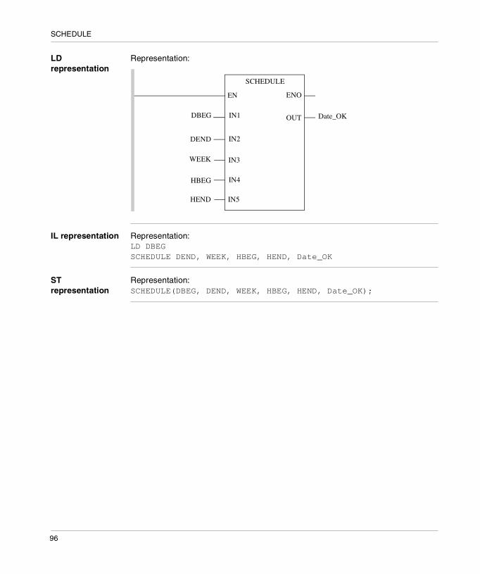
LD representation
Representation:
IL representation Representation:LD DBEGSCHEDULE DEND, WEEK, HBEG, HEND, Date_OK
ST representation
Representation:SCHEDULE(DBEG, DEND, WEEK, HBEG, HEND, Date_OK);
SCHEDULE
ENOEN
DBEG
DEND
WEEK
HBEG
HEND
IN1 Date_OKOUT
IN2
IN3
IN4
IN5
96
SCHEDULE
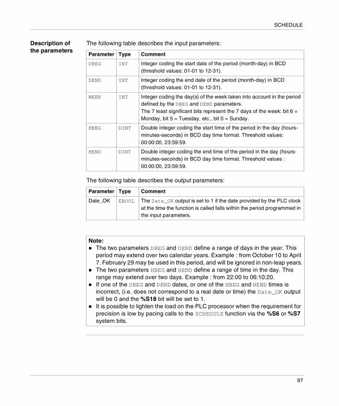
Description of the parameters
The following table describes the input parameters:
The following table describes the output parameters:
Parameter Type Comment
DBEG INT Integer coding the start date of the period (month-day) in BCD (threshold values: 01-01 to 12-31).
DEND INT Integer coding the end date of the period (month-day) in BCD (threshold values: 01-01 to 12-31).
WEEK INT Integer coding the day(s) of the week taken into account in the period defined by the DBEG and DEND parameters.The 7 least significant bits represent the 7 days of the week: bit 6 = Monday, bit 5 = Tuesday, etc., bit 0 = Sunday.
HBEG DINT Double integer coding the start time of the period in the day (hours-minutes-seconds) in BCD day time format. Threshold values: 00:00:00, 23:59:59.
HEND DINT Double integer coding the end time of the period in the day (hours-minutes-seconds) in BCD day time format. Threshold values : 00:00:00, 23:59:59.
Parameter Type Comment
Date_OK EBOOL The Date_OK output is set to 1 if the date provided by the PLC clock at the time the function is called falls within the period programmed in the input parameters.
Note: � The two parameters DBEG and DEND define a range of days in the year. This
period may extend over two calendar years. Example : from October 10 to April 7. February 29 may be used in this period, and will be ignored in non-leap years.
� The two parameters HBEG and HEND define a range of time in the day. This range may extend over two days. Example : from 22:00 to 06:10:20.
� If one of the DBEG and DEND dates, or one of the HBEG and HEND times is incorrect, (i.e. does not correspond to a real date or time) the Date_OK output will be 0 and the %S18 bit will be set to 1.
� It is possible to lighten the load on the PLC processor when the requirement for precision is low by pacing calls to the SCHEDULE function via the %S6 or %S7 system bits.
97
SCHEDULE
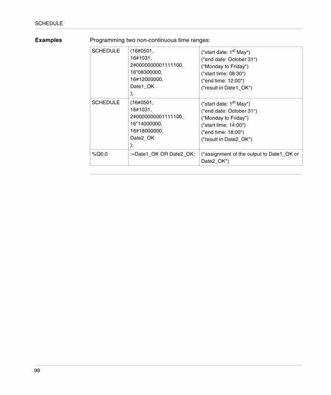
Examples Programming two non-continuous time ranges:
SCHEDULE (16#0501,16#1031,2#0000000001111100,16"08300000,16#12000000,Date1_OK);
(*start date: 1st May*)(*end date: October 31*)(*Monday to Friday*)(*start time: 08:30*)(*end time: 12:00*)(*result in Date1_OK*)
SCHEDULE (16#0501,16#1031,2#0000000001111100,16"14000000,16#18000000,Date2_OK);
(*start date: 1st May*)(*end date: October 31*)(*Monday to Friday*)(*start time: 14:00*)(*end time: 18:00*)(*result in Date2_OK*)
%Q0.0 :=Date1_OK OR Date2_OK; (*assignment of the output to Date1_OK or Date2_OK*)
98
22
WRTC_DT: Updating the system dateDescription
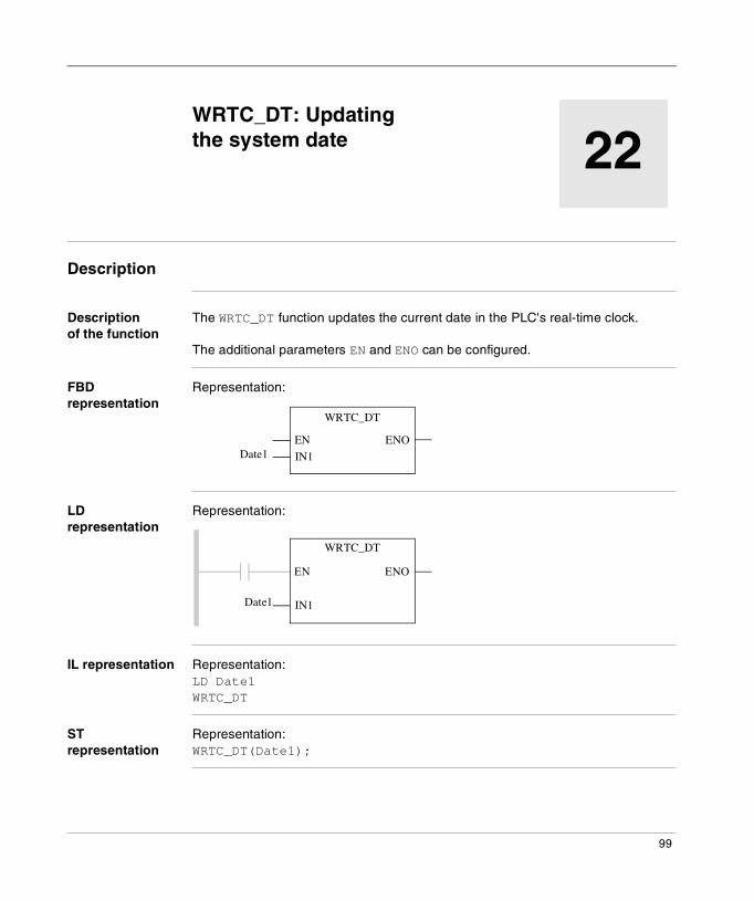
Description of the function
The WRTC_DT function updates the current date in the PLC's real-time clock.
The additional parameters EN and ENO can be configured.
FBD representation
Representation:
LD representation
Representation:
IL representation Representation:LD Date1WRTC_DT
ST representation
Representation:WRTC_DT(Date1);
WRTC_DT
Date1 IN1
ENOEN
WRTC_DT
Date1
ENOEN
IN1
99
WRTC_DT
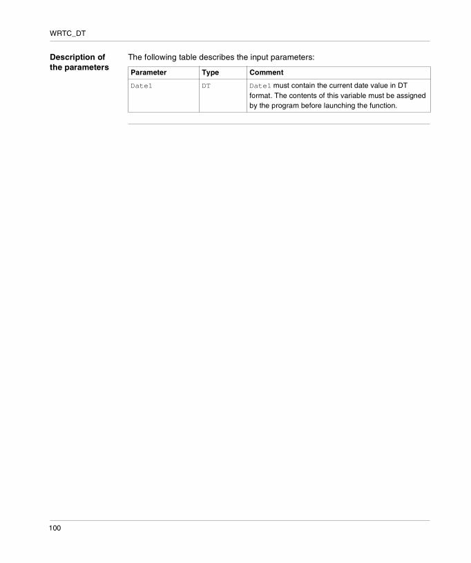
Description of the parameters
The following table describes the input parameters:
Parameter Type Comment
Date1 DT Date1 must contain the current date value in DT format. The contents of this variable must be assigned by the program before launching the function.
100
Appendices
Introduction
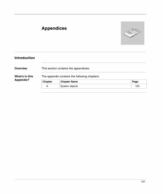
Overview This section contains the appendicies.
What's in this Appendix?
The appendix contains the following chapters:
Chapter Chapter Name Page
A System objects 103
101

Appendices
102
A
System objectsAt a Glance
Subject of this Chapter
This chapter describes the system bits and words of Unity Pro language.
Note: The symbols, associated with each bit object or system word, mentioned in the descriptive tables of these objects, are not implemented as standard in the software, but can be entered using the data editor.They are proposed in order to ensure the homogeneity of their names in the different applications.
What's in this Chapter?
This chapter contains the following topics:
Topic Page
System bit introduction 104
Description of system bits %S0 to %S7 105
Description of system bits %S15 to %S21 106
Description of system bits %S30 to %S59 109
Description of system words %SW12 to %SW18 112
Description of system words %SW48 to %SW59 114
Description of System Words %SW60 to %SW63: 116
103
System objects
System bit introduction
General The Premium, Atrium and Quantum PLCs use %Si system bits which indicate the state of the PLC, or they can be used to control how it operates.These bits can be tested in the user program to detect any functional development requiring a set processing procedure.Some of these bits must be reset to their initial or normal state by the program. However, the system bits that are reset to their initial or normal state by the system must not be reset by the program or by the terminal.
104

System objects
Description of system bits %S0 to %S7
Detailed description
Description of system bits %S0 to %S7:
BitSymbol
Function Description Initial state
Quantum Premium Atrium
%S0COLDSTART
Cold start Normally on 0, this bit is set on 1 by:� power restoral with loss of data (battery
fault),� the user program,� the terminal,� a change of cartridge.� program loading.This bit is set to 1 during the first complete restored cycle of the PLC either in RUN or in STOP mode. It is reset to 0 by the system before the following cycle.
1(1 cycle)
YES YES
%S1WARMSTART
Warm restart
Normally at 0, this bit is set to 1 by :� power restoral with data save,� the user program,� the terminal,� action on change of cartridge.It is reset to 0 by the system at the end of the first complete cycle and before the outputs are updated.
0 YES YES
%S4TB10MS
Timebase 10 ms
An internal timer regulates the change in status of this bit.It is asynchronous in relation to the PLC cycle.Graph:
- YES YES
%S5TB100MS
Timebase 100 ms
Idem %S4 - YES YES
%S6TB1SEC
Time base 1 s
Idem %S4 - YES YES
%S7TB1MIN
Time base 1 min
Idem %S4 - YES YES
5ms 5ms
105

System objects
Description of system bits %S15 to %S21
Detailed description
Description of system bits %S15 to %S21:
BitSymbol
Function Description Initial state
Quantum Premium Atrium
%S15STRINGERROR
Character string fault
Normally set to 0, this is set to 1 when the destination zone for a character string transfer is not of sufficient size (including the amount of characters and the end character of the character string) to receive this character string. The application stops in error state if the %S78 bit has been to set to 1.This bit must be reset to 0 by the application.
0 YES YES
%S16IOERRTSK
Task input/output fault
Normally set to 1, this is set to 0 by the system when a fault occurs on an in-rack I/O module or a Fipio device configured in the task.This bit must be reset to 1 by the user.
1 YES YES
%S17CARRY
Rotate shift output
Normally at 0.During a rotate shift operation, this takes the state of the outgoing bit.
0 YES YES
106
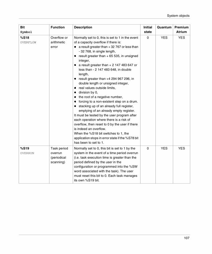
System objects
%S18OVERFLOW
Overflow or arithmetic error
Normally set to 0, this is set to 1 in the event of a capacity overflow if there is:� a result greater than + 32 767 or less than
- 32 768, in single length,� result greater than + 65 535, in unsigned
integer,� a result greater than + 2 147 483 647 or
less than - 2 147 483 648, in double length,
� result greater than +4 294 967 296, in double length or unsigned integer,
� real values outside limits,� division by 0,� the root of a negative number,� forcing to a non-existent step on a drum.� stacking up of an already full register,
emptying of an already empty register.It must be tested by the user program after each operation where there is a risk of overflow, then reset to 0 by the user if there is indeed an overflow.When the %S18 bit switches to 1, the application stops in error state if the %S78 bit has been to set to 1.
0 YES YES
%S19OVERRUN
Task period overrun (periodical scanning)
Normally set to 0, this bit is set to 1 by the system in the event of a time period overrun (i.e. task execution time is greater than the period defined by the user in the configuration or programmed into the %SW word associated with the task). The user must reset this bit to 0. Each task manages its own %S19 bit.
0 YES YES
BitSymbol
Function Description Initial state
Quantum Premium Atrium
107

System objects
%S20INDEXOVF
Index overflow
Normally set to 0, this is set to 1 when the address of the indexed object becomes less than 0 or exceeds the number of objects declared in the configuration.In this case, it is as if the index were equal to 0.It must be tested by the user program after each operation where there is a risk of overflow, then reset to 0 if there is indeed an overflow. When the %S20 bit switches to 1, the application stops in error state if the %S78 bit has been to set to 1.
0 YES YES
%S211RSTTASKRUN
First task cycle
Tested in a task (Mast, Fast, Aux0, Aux1, Aux2 Aux3), the bit %S21 indicates the first cycle of this task. %S21 is set to 1 at the start of the cycle and reset to zero at the end of the cycle.Notes: the bit %S21 does not have the same meaning in PL7 as in Unity Pro.
0 YES YES
BitSymbol
Function Description Initial state
Quantum Premium Atrium
CAUTION
%S16 for Quantum PLCs
On Quantum, communication errors from modules (NOM, NOE, NWM, CRA, CRP) and MMS modules are not reported on bits %S10 and %S16.It is entirely your responsibility to ensure that these system bits are used correctly
Failure to follow this precaution can result in injury or equipment damage.
108

System objects
Description of system bits %S30 to %S59
Detailed description
Description of system bits %S30 to %S59:
BitSymbol
Function Description Initial state
Quantum Premium Atrium
%S30MASTACT
Activation/deactivation of the master task
Normally set to 1, the user setting the bit to 0 deactivates the master task.This bit is taken into consideration by the system at the end of each MAST task cycle.
1 YES YES
%S31FASTACT
Activation/deactivation of the fast task
Idem %S30 for the FAST task. 0 YES YES
%S32AUX0ACT
Activation/deactivation of the auxiliary task 0
Idem %S30 for the AUX0 task. 0 YES YES
%S33AUX1ACT
Activation/deactivation of the auxiliary task 1
Idem %S30 for the AUX1 task. 0 YES YES
%S34AUX2ACT
Activation/deactivation of the auxiliary task 2
Idem %S30 for the AUX2 task. 0 YES YES
%S35AUX3ACT
Activation/deactivation of the auxiliary task 3
Idem %S30 for the AUX3 task. 0 YES YES
%S38ACTIVEVT
Enabling/inhibition of events
Normally set to 1, the user setting the bit to 0 causes events to be inhibited.
1 YES YES
%S39EVTOVR
Saturation in event processing
This bit is set to 1 by the system to indicate that one or more events cannot be processed following saturation of the queues.The user must reset this bit to 0.
0 YES YES
109
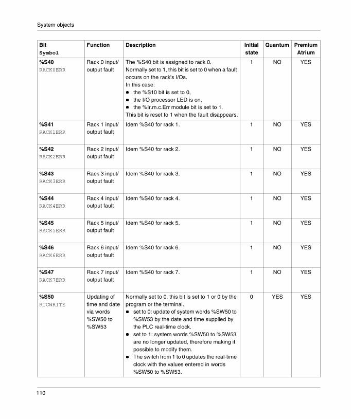
System objects
%S40RACK0ERR
Rack 0 input/output fault
The %S40 bit is assigned to rack 0. Normally set to 1, this bit is set to 0 when a fault occurs on the rack's I/Os. In this case:� the %S10 bit is set to 0,� the I/O processor LED is on,� the %Ir.m.c.Err module bit is set to 1.This bit is reset to 1 when the fault disappears.
1 NO YES
%S41RACK1ERR
Rack 1 input/output fault
Idem %S40 for rack 1. 1 NO YES
%S42RACK2ERR
Rack 2 input/output fault
Idem %S40 for rack 2. 1 NO YES
%S43RACK3ERR
Rack 3 input/output fault
Idem %S40 for rack 3. 1 NO YES
%S44RACK4ERR
Rack 4 input/output fault
Idem %S40 for rack 4. 1 NO YES
%S45RACK5ERR
Rack 5 input/output fault
Idem %S40 for rack 5. 1 NO YES
%S46RACK6ERR
Rack 6 input/output fault
Idem %S40 for rack 6. 1 NO YES
%S47RACK7ERR
Rack 7 input/output fault
Idem %S40 for rack 7. 1 NO YES
%S50RTCWRITE
Updating of time and date via words %SW50 to %SW53
Normally set to 0, this bit is set to 1 or 0 by the program or the terminal.� set to 0: update of system words %SW50 to
%SW53 by the date and time supplied by the PLC real-time clock.
� set to 1: system words %SW50 to %SW53 are no longer updated, therefore making it possible to modify them.
� The switch from 1 to 0 updates the real-time clock with the values entered in words %SW50 to %SW53.
0 YES YES
BitSymbol
Function Description Initial state
Quantum Premium Atrium
110
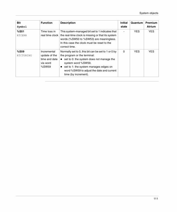
System objects
%S51RTCERR
Time loss in real time clock
This system-managed bit set to 1 indicates that the real-time clock is missing or that its system words (%SW50 to %SW53) are meaningless. In this case the clock must be reset to the correct time.
- YES YES
%S59RTCTUNING
Incremental update of the time and date via word %SW59
Normally set to 0, this bit can be set to 1 or 0 by the program or the terminal:� set to 0: the system does not manage the
system word %SW59,� set to 1: the system manages edges on
word %SW59 to adjust the date and current time (by increment).
0 YES YES
BitSymbol
Function Description Initial state
Quantum Premium Atrium
111
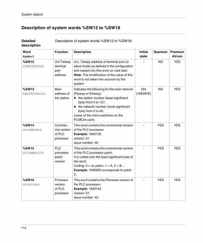
System objects
Description of system words %SW12 to %SW18
Detailed description
Description of system words %SW12 to %SW18:
WordSymbol
Function Description Initial state
Quantum Premium Atrium
%SW12UTWPORTADDR
Uni-Telway terminal port address
Uni_Telway address of terminal port (in slave mode) as defined in the configuration and loaded into this word on cold start.Note: The modification of the value of this word is not taken into account by the system
- NO YES
%SW13XWAYNETWADDR
Main address of the station
Indicates the following for the main network (Fipway or Ethway):� the station number (least significant
byte) from 0 to 127,� the network number (most significant
byte) from 0 to 63,(value of the micro-switches on the PCMCIA card).
254(16#00FE)
NO YES
%SW14OSCOMMVERS
Commer-cial version of PLC processor
This word contains the commercial version of the PLC processor.Example: 16#0135version: 01issue number: 35
- YES YES
%SW15OSCOMMPATCH
PLC processor patch version
This word contains the commercial version of the PLC processor patch.It is coded onto the least significant byte of the word.Coding: 0 = no patch, 1 = A, 2 = B...Example: 16#0003 corresponds to patch C.
- YES YES
%SW16OSINTVERS
Firmware version of PLC processor
This word contains the Firmware version of the PLC processor.Example: 16#0143version: 01issue number: 43
- YES YES
112
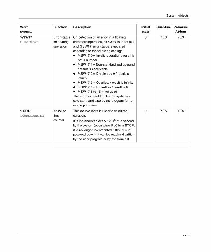
System objects
%SW17FLOATSTAT
Error status on floating operation
On detection of an error in a floating arithmetic operation, bit %SW18 is set to 1 and %SW17 error status is updated according to the following coding:� %SW17.0 = Invalid operation / result is
not a number� %SW17.1 = Non-standardized operand
/ result is acceptable� %SW17.2 = Division by 0 / result is
infinity� %SW17.3 = Overflow / result is infinity� %SW17.4 = Underflow / result is 0� %SW17.5 to 15 = not usedThis word is reset to 0 by the system on cold start, and also by the program for re-usage purposes.
0 YES YES
%SD18100MSCOUNTER
Absolute time counter
This double word is used to calculate duration.
It is incremented every 1/10th of a second by the system (even when PLC is in STOP, it is no longer incremented if the PLC is powered down). It can be read and written by the user program or by the terminal.
0 YES YES
WordSymbol
Function Description Initial state
Quantum Premium Atrium
113
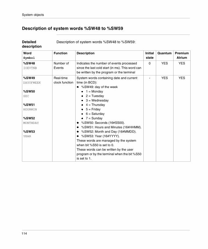
System objects
Description of system words %SW48 to %SW59
Detailed description
Description of system words %SW48 to %SW59:
WordSymbol
Function Description Initial state
Quantum Premium Atrium
%SW48IOEVTNB
Number of Events
Indicates the number of events processed since the last cold start (in ms). This word can be written by the program or the terminal
0 YES YES
%SW49DAYOFWEEK
%SW50SEC
%SW51HOURMIN
%SW52MONTHDAY
%SW53YEAR
Real-time clock function
System words containing date and current time (in BCD):� %SW49: day of the week
� 1 = Monday� 2 = Tuesday� 3 = Wednesday� 4 = Thursday� 5 = Friday� 6 = Saturday� 7 = Sunday
� %SW50: Seconds (16#SS00).� %SW51: Hours and Minutes (16#HHMM).� %SW52: Month and Day (16#MMDD).� %SW53: Year (16#YYYY).These words are managed by the system when bit %S50 is set to 0.These words can be written by the user program or by the terminal when the bit %S50 is set to 1.
- YES YES
114
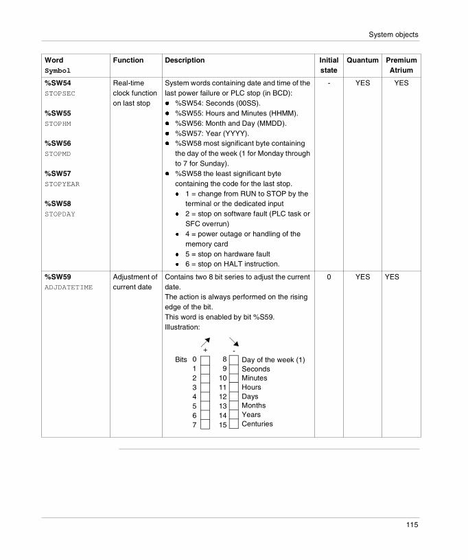
System objects
%SW54STOPSEC
%SW55STOPHM
%SW56STOPMD
%SW57STOPYEAR
%SW58STOPDAY
Real-time clock function on last stop
System words containing date and time of the last power failure or PLC stop (in BCD):� %SW54: Seconds (00SS).� %SW55: Hours and Minutes (HHMM).� %SW56: Month and Day (MMDD).� %SW57: Year (YYYY).� %SW58 most significant byte containing
the day of the week (1 for Monday through to 7 for Sunday).
� %SW58 the least significant byte containing the code for the last stop.� 1 = change from RUN to STOP by the
terminal or the dedicated input� 2 = stop on software fault (PLC task or
SFC overrun)� 4 = power outage or handling of the
memory card� 5 = stop on hardware fault� 6 = stop on HALT instruction.
- YES YES
%SW59ADJDATETIME
Adjustment of current date
Contains two 8 bit series to adjust the current date.The action is always performed on the rising edge of the bit.This word is enabled by bit %S59.Illustration:
0 YES YES
WordSymbol
Function Description Initial state
Quantum Premium Atrium
01234567
89
101112131415
Bits+ -
Day of the week (1)SecondsMinutesHoursDaysMonthsYearsCenturies
115
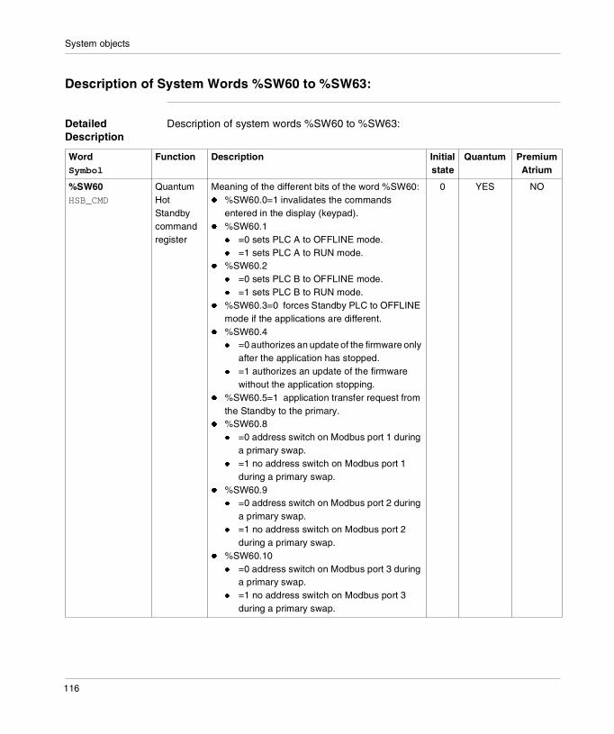
System objects
Description of System Words %SW60 to %SW63:
Detailed Description
Description of system words %SW60 to %SW63:
WordSymbol
Function Description Initial state
Quantum PremiumAtrium
%SW60HSB_CMD
Quantum Hot Standby command register
Meaning of the different bits of the word %SW60:� %SW60.0=1 invalidates the commands
entered in the display (keypad).� %SW60.1
� =0 sets PLC A to OFFLINE mode.� =1 sets PLC A to RUN mode.
� %SW60.2� =0 sets PLC B to OFFLINE mode.� =1 sets PLC B to RUN mode.
� %SW60.3=0 forces Standby PLC to OFFLINE mode if the applications are different.
� %SW60.4� =0 authorizes an update of the firmware only
after the application has stopped.� =1 authorizes an update of the firmware
without the application stopping.� %SW60.5=1 application transfer request from
the Standby to the primary.� %SW60.8
� =0 address switch on Modbus port 1 during a primary swap.
� =1 no address switch on Modbus port 1 during a primary swap.
� %SW60.9� =0 address switch on Modbus port 2 during
a primary swap.� =1 no address switch on Modbus port 2
during a primary swap.� %SW60.10
� =0 address switch on Modbus port 3 during a primary swap.
� =1 no address switch on Modbus port 3 during a primary swap.
0 YES NO
116
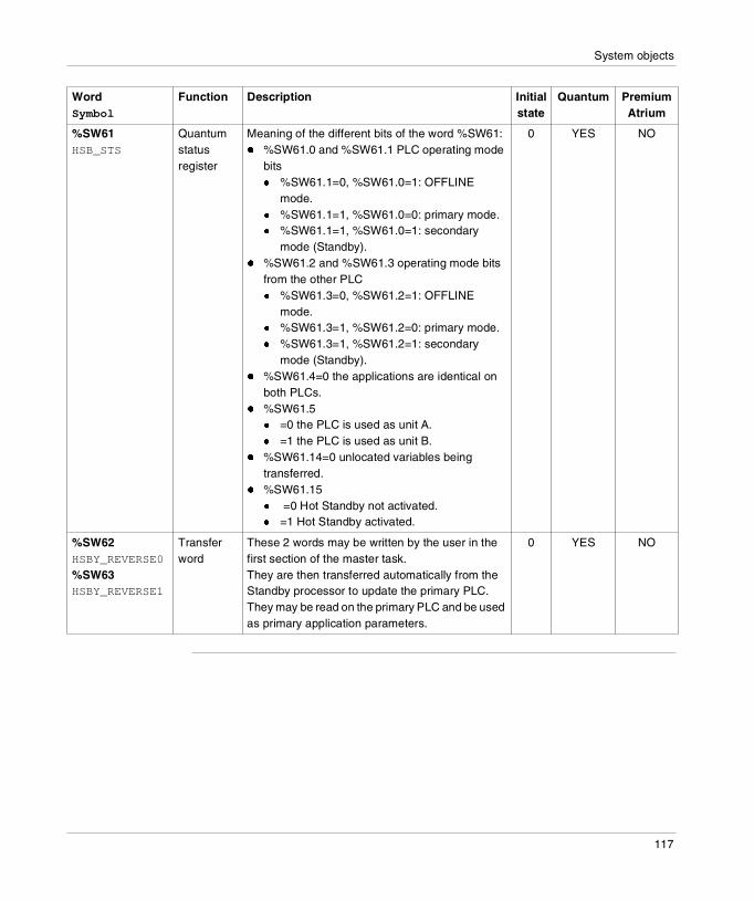
System objects
%SW61HSB_STS
Quantum status register
Meaning of the different bits of the word %SW61:� %SW61.0 and %SW61.1 PLC operating mode
bits� %SW61.1=0, %SW61.0=1: OFFLINE
mode.� %SW61.1=1, %SW61.0=0: primary mode.� %SW61.1=1, %SW61.0=1: secondary
mode (Standby).� %SW61.2 and %SW61.3 operating mode bits
from the other PLC� %SW61.3=0, %SW61.2=1: OFFLINE
mode.� %SW61.3=1, %SW61.2=0: primary mode.� %SW61.3=1, %SW61.2=1: secondary
mode (Standby).� %SW61.4=0 the applications are identical on
both PLCs.� %SW61.5
� =0 the PLC is used as unit A.� =1 the PLC is used as unit B.
� %SW61.14=0 unlocated variables being transferred.
� %SW61.15� =0 Hot Standby not activated.� =1 Hot Standby activated.
0 YES NO
%SW62 HSBY_REVERSE0
%SW63HSBY_REVERSE1
Transfer word
These 2 words may be written by the user in the first section of the master task. They are then transferred automatically from the Standby processor to update the primary PLC.They may be read on the primary PLC and be used as primary application parameters.
0 YES NO
WordSymbol
Function Description Initial state
Quantum PremiumAtrium
117

System objects
118
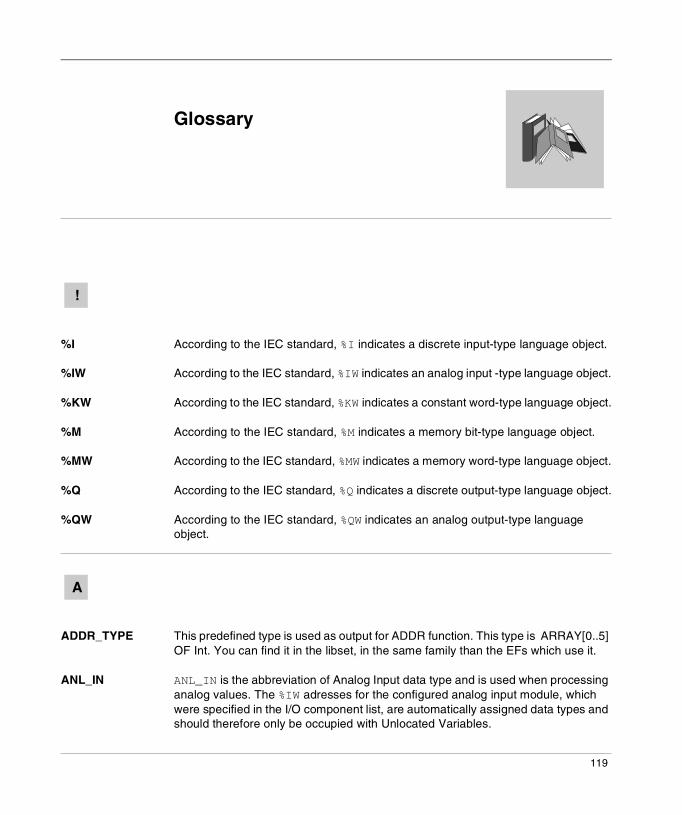
Glossary
%I According to the IEC standard, %I indicates a discrete input-type language object.
%IW According to the IEC standard, %IW indicates an analog input -type language object.
%KW According to the IEC standard, %KW indicates a constant word-type language object.
%M According to the IEC standard, %M indicates a memory bit-type language object.
%MW According to the IEC standard, %MW indicates a memory word-type language object.
%Q According to the IEC standard, %Q indicates a discrete output-type language object.
%QW According to the IEC standard, %QW indicates an analog output-type language object.
ADDR_TYPE This predefined type is used as output for ADDR function. This type is ARRAY[0..5] OF Int. You can find it in the libset, in the same family than the EFs which use it.
ANL_IN ANL_IN is the abbreviation of Analog Input data type and is used when processing analog values. The %IW adresses for the configured analog input module, which were specified in the I/O component list, are automatically assigned data types and should therefore only be occupied with Unlocated Variables.
!
A
119
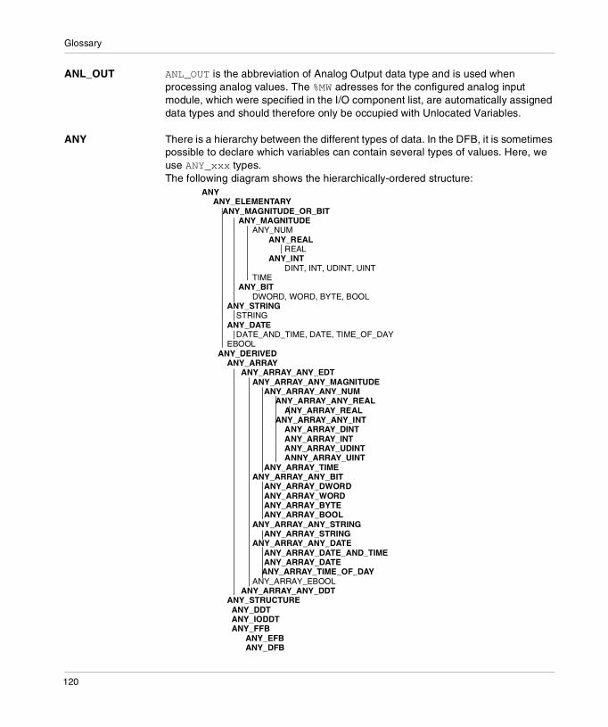
Glossary
ANL_OUT ANL_OUT is the abbreviation of Analog Output data type and is used when processing analog values. The %MW adresses for the configured analog input module, which were specified in the I/O component list, are automatically assigned data types and should therefore only be occupied with Unlocated Variables.
ANY There is a hierarchy between the different types of data. In the DFB, it is sometimes possible to declare which variables can contain several types of values. Here, we use ANY_xxx types. The following diagram shows the hierarchically-ordered structure:
ANY ANY_ELEMENTARY ANY_MAGNITUDE_OR_BIT ANY_MAGNITUDE ANY_NUM ANY_REAL REAL ANY_INT DINT, INT, UDINT, UINT TIME ANY_BIT DWORD, WORD, BYTE, BOOL ANY_STRING STRING ANY_DATE DATE_AND_TIME, DATE, TIME_OF_DAY EBOOL ANY_DERIVED ANY_ARRAY ANY_ARRAY_ANY_EDT ANY_ARRAY_ANY_MAGNITUDE ANY_ARRAY_ANY_NUM ANY_ARRAY_ANY_REAL ANY_ARRAY_REAL ANY_ARRAY_ANY_INT ANY_ARRAY_DINT ANY_ARRAY_INT ANY_ARRAY_UDINT ANNY_ARRAY_UINT ANY_ARRAY_TIME ANY_ARRAY_ANY_BIT ANY_ARRAY_DWORD ANY_ARRAY_WORD ANY_ARRAY_BYTE ANY_ARRAY_BOOL ANY_ARRAY_ANY_STRING ANY_ARRAY_STRING ANY_ARRAY_ANY_DATE ANY_ARRAY_DATE_AND_TIME ANY_ARRAY_DATE ANY_ARRAY_TIME_OF_DAY ANY_ARRAY_EBOOL ANY_ARRAY_ANY_DDT ANY_STRUCTURE ANY_DDT ANY_IODDT ANY_FFB ANY_EFB ANY_DFB
120
Glossary
ARRAY An ARRAY is a table of elements of the same type.The syntax is as follows: ARRAY [<terminals>] OF <Type>Example:ARRAY [1..2] OF BOOL is a one-dimensional table made up of two BOOL-type elements.ARRAY [1..10, 1..20] OF INT is a two-dimensional table made up of 10x20 INT-type elements.
Base 10 literals A literal value in base 10 is used to represent a decimal integer value. This value can be preceded by the signs "+" and "-". If the character "_" is employed in this literal value, it is not significant.Example:-12, 0, 123_456, +986
Base 16 Literals An literal value in base 16 is used to represent an integer in hexadecimal. The base is determined by the number "16" and the sign "#". The signs "+" and "-" are not allowed. For greater clarity when reading, you can use the sign "_" between bits.Example:16#F_F or 16#FF (in decimal 255)16#F_F or 16#FF (in decimal 224)
Base 2 Literals A literal value in base 2 is used to represent a binary integer. The base is determined by the number "2" and the sign "#". The signs "+" and "-" are not allowed. For greater clarity when reading, you can use the sign "_" between bits.Example:2#1111_1111 or 2#11111111 (in decimal 255)2#1110_0000 or 2#11100000 (in decimal 224)
Base 8 Literals A literal value in base 8 is used to represent an octal integer. The base is determined by the number "8" and the sign "#". The signs "+" and "-" are not allowed. For greater clarity when reading, you can use the sign "_" between bits.Example:8#3_77 or 8#377 (in decimal 255)8#34_0 or 8#340 (in decimal 224)
B
121

Glossary
BCD BCD is the abbreviation of Binary Coded Decimal format BCD is used to represent decimal numbers between 0 and 9 using a group of four bits (half-byte).In this format, the four bits used to code the decimal numbers have a range of unused combinations.Example of BCD coding: � the number 2450 � is coded: 0010 0100 0101 0000
BOOL BOOL is the abbreviation of Boolean type. This is the elementary data item in computing. A BOOL type variable has a value of either: 0 (FALSE) or 1 (TRUE).A BOOL type word extract bit, for example: %MW10.4.
BYTE When 8 bits are put together, this is callad a BYTE. A BYTE is either entered in binary, or in base 8.The BYTE type is coded in an 8 bit format, which, in hexadecimal, ranges from 16#00 to 16#FF
DATE The DATE type coded in BCD in 32 bit format contains the following information: � the year coded in a 16-bit field,� the month coded in an 8-bit field,� the day coded in an 8-bit field.The DATE type is entered as follows: D#<Year>-<Month>-<Day> This table shows the lower/upper limits in each field:
DATE_AND_TIME
see DT
D
Field Limits Comment
Year [1990,2099] Year
Month [01,12] The left 0 is always displayed, but can be omitted at the time of entry
Day [01,31] For the months 01\03\05\07\08\10\12
[01,30] For the months 04\06\09\11
[01,29] For the month 02 (leap years)
[01,28] For the month 02 (non leap years)
122
Glossary
DBCD Representation of a Double BCD-format double integer.The Binary Coded Decimal (BCD) format is used to represent decimal numbers between 0 and 9 using a group of four bits.In this format, the four bits used to code the decimal numbers have a range of unused combinations.Example of DBCD coding: � the number 78993016� is coded: 0111 1000 1001 1001 0011 0000 0001 0110
DDT DDT is the abbreviation of Derived Data Type.A derived data type is a set of elements of the same type (ARRAY) or of various types (structure)
DFB DFB is the abbrevation of Derived Function Block.DFB types are function blocks that can be programmed by the user ST, IL, LD or FBD.By using DFB types in an application, it is possible to:� simplify the design and input of the program,� increase the legibility of the program,� facilitate the debugging of the program,� reduce the volume of the generated code.
DINT DINT is the abbrevation of Double Integer format (coded on 32 bits). The lower and upper limits are as follows: -(2 to the power of 31) to (2 to the power of 31) - 1.Example:-2147483648, 2147483647, 16#FFFFFFFF.
DT DT is the abbreviation of Date and Time.The DT type coded in BCD in 64 bit format contains the following information:� The year coded in a 16-bit field,� the month coded in an 8-bit field,� the day coded in an 8-bit field,� the hour coded in a 8-bit field,� the minutes coded in an 8-bit field,� the seconds coded in an 8-bit field.
The DT type is entered as follows:DT#<Year>-<Month>-<Day>-<Hour>:<Minutes>:<Seconds>
Note: The 8 least significant bits are unused.
123
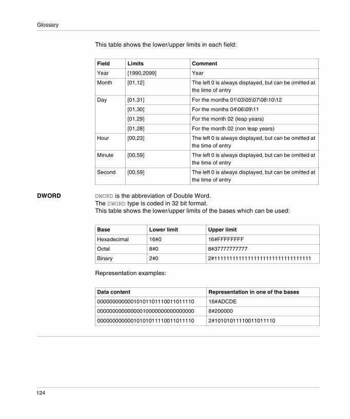
Glossary
This table shows the lower/upper limits in each field:
DWORD DWORD is the abbreviation of Double Word.The DWORD type is coded in 32 bit format.This table shows the lower/upper limits of the bases which can be used:
Representation examples:
Field Limits Comment
Year [1990,2099] Year
Month [01,12] The left 0 is always displayed, but can be omitted at the time of entry
Day [01,31] For the months 01\03\05\07\08\10\12
[01,30] For the months 04\06\09\11
[01,29] For the month 02 (leap years)
[01,28] For the month 02 (non leap years)
Hour [00,23] The left 0 is always displayed, but can be omitted at the time of entry
Minute [00,59] The left 0 is always displayed, but can be omitted at the time of entry
Second [00,59] The left 0 is always displayed, but can be omitted at the time of entry
Base Lower limit Upper limit
Hexadecimal 16#0 16#FFFFFFFF
Octal 8#0 8#37777777777
Binary 2#0 2#11111111111111111111111111111111
Data content Representation in one of the bases
00000000000010101101110011011110 16#ADCDE
00000000000000010000000000000000 8#200000
00000000000010101011110011011110 2#10101011110011011110
124

Glossary
EBOOL EBOOL is the abbrevation of Extended Boolean type. It can be used to manage rising or falling edges, as well as forcing.An EBOOL type variable takes up one byte of memory.
EF Is the abbreviation of Elementary Function.This is a block which is used in a program, and which performs a predefined software function.A function has no internal status information. Multiple invocations of the same function using the same input parameters always supply the same output values. Details of the graphic form of the function invocation can be found in the "[Functional block (instance)] ". In contrast to the invocation of the function blocks, function invocations only have a single unnamed output, whose name is the same as the function. In FBD each invocation is denoted by a unique [number] via the graphic block, this number is automatically generated and can not be altered.You position and set up these functions in your program in order to carry out your application. You can also develop other functions using the SDKC development kit.
EFB Is the abbreviation for Elementary Function Block.This is a block which is used in a program, and which performs a predefined software function.EFBs have internal statuses and parameters. Even where the inputs are identical, the output values may be different. For example, a counter has an output which indicates that the preselection value has been reached. This output is set to 1 when the current value is equal to the preselection value.
Elementary Function
see EF
EN EN means ENable, this is an optional block input. When EN is activated, an ENO output is automatically drafted. If EN = 0, the block is not activated, its internal program is not executed and ENO is set to 0.If EN = 1, the internal program of the block is executed, and ENO is set to 1 by the system. If an error occurs, ENO is set to 0.If EN is not connected, it is automatically set to 1.
E
125
Glossary
ENO ENO means Error NOtification, this is the output associated to the optional input EN. If ENO is set to 0 (caused by EN=0 or in case of an execution error),� the outputs of function blocks remain in the status they were in for the last correct
executed scanning cycle and� the output(s) of functions and procedures are set to "0".
FBD FBD is the abbreviation of Function Block Diagram. FBD is a graphic programming language that operates as a logic diagram. In addition to the simple logic blocks (AND, OR, etc.), each function or function block of the program is represented using this graphic form. For each block, the inputs are located to the left and the outputs to the right. The outputs of the blocks can be linked to the inputs of other blocks to form complex expressions.
FFB Collective term for EF (Elementary Function), EFB (Elementary Function Block) and DFB (Derived Function block)
Function see EF
Function Block Diagram
see FBD
F
126

Glossary
GRAY Gray or "reflected binary" code is used to code a numerical value being developed into a chain of binary configurations that can be differentiated by the change in status of one and only one bit. This code can be used, for example, to avoid the following random event: in pure binary, the change of the value 0111 to 1000 can produce random numbers between 0 and 1000, as the bits do not change value altogether simultaneously.Equivalence between decimal, BCD and Gray:
IEC 61131-3 International standard: Programmable Logic Controls Part 3: Programming languages.
IL IL is the abbreviation of Instruction List.This language is a series of basic instructions. This language is very close to the assembly language used to program processors.Each instruction is composed of an instruction code and an operand.
INF Used to indicate that a number overruns the allowed limits. For a number of Integers, the value ranges (shown in gray) are as follows:
When a calculation result is: � less than -3.402824e+38, the symbol -INF (for -infinite) is displayed,� greater than +3.402824e+38, the symbol INF (for +infinite) is displayed.
G
Decimal 0 1 2 3 4 5 6 7 8 9
BCD 0000 0001 0010 0011 0100 0101 0110 0111 1000 1001
Gray 0000 0001 0011 0010 0110 0111 0101 0100 1100 1101
I
-3.402824e+38 3.402824e+38-1.1754944e-38 1.1754944e-380.0
INF-INF
127
Glossary
INT INT is the abbreviation of single integer format (coded on 16 bits). The lower and upper limits are as follows: -(2 to the power of 15) to (2 to the power of 15) - 1.Example:-32768, 32767, 2#1111110001001001, 16#9FA4.
Integer Literals Integer literal are used to enter integer values in the decimal system. The values can have a preceding sign (+/-). Individual underlines (_ ) between numbers are not significant.Example:-12, 0, 123_456, +986
IODDT IODDT is the abbreviation of Input/Output Derived Data Type. The term IODDT designates a structured data type representing a module or a channel of a PLC module. Each application expert module possesses its own IODDTs.
Keyword A keyword is a unique combination of characters used as a syntactical programming language element (See annex B definition of the IEC standard 61131-3. All the key words used in Unity Pro and of this standard are listed in annex C of the IEC standard 61131-3. These keywords cannot be used as identifiers in your program (names of variables, sections, DFB types, etc.)).
LD LD is the abbreviation of Ladder Diagram. LD is a programming language, representing the instructions to be carried out in the form of graphic diagrams very close to a schematic electrical diagram (contacts, coils, etc.).
Located variables
A located variable is a variable for which it is possible to know its position in the PLC memory. For example, the variable Water_pressure, is associated with%MW102. Water_pressure is said to be localized.
K
L
128
Glossary
Multiple Token Operating mode of an SFC. In multitoken mode, the SFC may possess several active steps at the same time.
Naming conventions (Identifier)
An identifier is a sequence of letters, numbers and underlines beginning with a letter or underline (e.g. name of a function block type, an instance, a variable or a section). Letters from national character sets (e.g: ö,ü, é, õ) can be used except in project and DFB names. Underlines are significant in identifiers; e.g. A_BCD and AB_CD are interpreted as different identifiers. Multiple leading underlines and consecutive underlines are invalid.Identifiers cannot contain spaces. Not case sensitive; e.g. ABCD and abcd are interpreted as the same identifier. According to IEC 61131-3 leading digits are not allowed in identifiers. Nevertheless, you can use them if you activate in dialog Tools → Project settings in tab Language extensions the ceck box Leading digits.Identifiers cannot be keywords.
NAN Used to indicate that a result of an operation is not a number (NAN = Not A Number).Example: calculating the square root of a negative number.
M
N
Note: The IEC 559 standard defines two classes of NAN: quiet NAN (QNAN) and signaling NaN (SNaN) QNAN is a NAN with the most significant fraction bit set and a SNAN is a NAN with the most significant fraction bit clear (Bit number 22). QNANs are allowed to propagate through most arithmetic operations without signaling an exception. SNAN generally signal an invalid-operation exception whenever they appear as operands in arithmetic operations (See %SW17 and %S18).
129
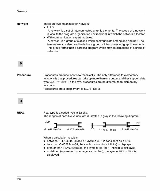
Glossary
Network There are two meanings for Network.� In LD:
A network is a set of interconnected graphic elements. The scope of a network is local to the program organization unit (section) in which the network is located.
� With communication expert modules: A network is a group of stations which communicate among one another. The term network is also used to define a group of interconnected graphic elements. This group forms then a part of a program which may be composed of a group of networks.
Procedure Procedures are functions view technically. The only difference to elementary functions is that procedures can take up more than one output and they support data type VAR_IN_OUT. To the eye, procedures are no different than elementary functions. Procedures are a supplement to IEC 61131-3.
REAL Real type is a coded type in 32 bits.The ranges of possible values are illustrated in gray in the following diagram:
When a calculation result is: � between -1.175494e-38 and 1.175494e-38 it is considerd as a DEN,� less than -3.402824e+38, the symbol -INF (for - infinite) is displayed,� greater than +3.402824e+38, the symbol INF (for +infinite) is displayed,� undefined (square root of a negative number), the symbol NAN or NAN is
displayed.
P
R
-3.402824e+38 3.402824e+38-1.1754944e-38 1.1754944e-380.0
INF-INF
130
Glossary
Real Literals An literal real value is a number expressed in one or more decimals.Example:-12.0, 0.0, +0.456, 3.14159_26
Real Literals with Exponent
An Literal decimal value can be expressed using standard scientific notation. The representation is as follows: mantissa + exponential.Example:-1.34E-12 or -1.34e-121.0E+6 or 1.0e+61.234E6 or 1.234e6
SFC SFC is the abbreviation of Sequential Function Chart.SFC enables the operation of a sequential automation device to be represented graphically and in a structured manner. This graphic description of the sequential behavior of an automation device, and the various situations which result from it, is performed using simple graphic symbols.
Single Token Operating mode of an SFC chart for which only a single step can be active at any one time.
ST ST is the abbreviation of Structured Text language.Structured Text language is an elaborated language close to computer programming languages. It enables you to structure series of instructions.
STRING A variable of the type STRING is an ASCII standard character string. A character string has a maximum length of 65534 characters.
Note: The IEC 559 standard defines two classes of NAN: quiet NAN (QNAN) and signaling NaN (SNaN) QNAN is a NAN with the most significant fraction bit set and a SNAN is a NAN with the most significant fraction bit clear (Bit number 22). QNANs are allowed to propagate through most arithmetic operations without signaling an exception. SNAN generally signal an invalid-operation exception whenever they appear as operands in arithmetic operations (See %SW17 and %S18).
Note: when an operand is a DEN (Denormalized number) the result is not significant.
S
131

Glossary
TIME The type TIME expresses a duration in milliseconds. Coded in 32 bits, this type
makes it possible to obtain periods from 0 to 2 32-1 milliseconds.The units of type TIME are the following: the days (d), the hours (h), the minutes (m), the seconds (s) and the milliseconds (ms). A literal value of the type TIME is represented by a combination of previous types preceded by T#, t#, TIME# or time#.Examples: T#25h15m, t#14.7S, TIME#5d10h23m45s3ms
Time literals The units of type TIME are the following: the days (d), the hours (h), the minutes (m), the seconds (s) and the milliseconds (ms). A literal value of the type TIME is represented by a combination of previous types preceded by T#, t#, TIME# or time#.Examples: T#25h15m, t#14.7S, TIME#5d10h23m45s3ms
TIME_OF_DAY see TOD
TOD TOD is the abbreviation of Time of Day.The TOD type coded in BCD in 32 bit format contains the following information:� the hour coded in a 8-bit field,� the minutes coded in an 8-bit field,� the seconds coded in an 8-bit field.
The Time of Day type is entered as follows: TOD#<Hour>:<Minutes>:<Seconds>This table shows the lower/upper limits in each field:
Example: TOD#23:59:45.
Token An active step of an SFC is known as a token.
T
Note: The 8 least significant bits are unused.
Field Limits Comment
Hour [00,23] The left 0 is always displayed, but can be omitted at the time of entry
Minute [00,59] The left 0 is always displayed, but can be omitted at the time of entry
Second [00,59] The left 0 is always displayed, but can be omitted at the time of entry
132

Glossary
TOPO_ADDR_TYPE
This predefined type is used as output for READ_TOPO_ADDR function. This type is an ARRAY[0..4] OF Int. You can find it in the libset, in the same family than the EFs which use it.
UDINT UDINT is the abbreviation of Unsigned Double Integer format (coded on 32 bits) unsigned. The lower and upper limits are as follows: 0 to (2 to the power of 32) - 1.Example:0, 4294967295, 2#11111111111111111111111111111111, 8#37777777777, 16#FFFFFFFF.
UINT UINT is the abbreviation of Unsigned integer format (coded on 16 bits). The lower and upper limits are as follows: 0 to (2 to the power of 16) - 1.Example:0, 65535, 2#1111111111111111, 8#177777, 16#FFFF.
Unlocated variable
An unlocated variable is a variable for which it is impossible to know its position in the PLC memory. A variable which have no address assigned is said to be unlocated.
Variable Memory entity of the type BOOL, WORD, DWORD, etc., whose contents can be modified by the program during execution.
U
V
133

Glossary
WORD The WORD type is coded in 16 bit format and is used to carry out processing on bit strings.This table shows the lower/upper limits of the bases which can be used:
Representation examples
W
Base Lower limit Upper limit
Hexadecimal 16#0 16#FFFF
Octal 8#0 8#177777
Binary 2#0 2#1111111111111111
Data content Representation in one of the bases
0000000011010011 16#D3
1010101010101010 8#125252
0000000011010011 2#11010011
134
CBAIndex
Symbols%S0, 105%S1, 105%S15, 106%S16, 106%S17, 106%S18, 107%S19, 107%S20, 108%S21, 108%S30, 109%S31, 109%S32, 109%S33, 109%S34, 109%S35, 109%S38, 109%S39, 109%S4, 105%S40, 110%S41, 110%S42, 110%S43, 110%S44, 110%S45, 110%S46, 110%S47, 110%S5, 105%S50, 110%S51, 111%S59, 111%S6, 105
%S7, 105%SD18, 113%SW12, 112%SW13, 112%SW14, 112%SW15, 112%SW16, 112%SW17, 113%SW48, 114%SW49, 114%SW50, 114%SW51, 114%SW52, 114%SW53, 114%SW54, 115%SW55, 115%SW56, 115%SW57, 115%SW58, 115%SW59, 115%SW60, 116%SW61, 117%SW62, 117%SW63, 117
Numerics100MSCOUNTER, 1131RSTTASKRUN, 108
135
Index
AACTIVEVT, 109ADJDATETIME, 115AUX0ACT, 109AUX1ACT, 109AUX2ACT, 109AUX3ACT, 109
BBlock types, 12
CCARRY, 106CLEARCHART, 55COLDSTART, 105Conditional FFB Call, 17
DDAYOFWEEK, 114Derived function block, 12
EElementary Function, 12Elementary function block, 12EN, 16ENO, 16Event management
HALT, 25MASKEVT, 31UNMASKEVT, 33
Events managementITCNTRL, 27
EVTOVR, 109
FFASTACT, 109FLOATSTAT, 113FREERUN, 85Free-running timer
FREERUN, 85
136
Freeze SequenceFREEZECHART, 59
FREEZECHART, 59
GGlobal masking of events
MASKEVT, 31
HHALT, 25Hot Stand By
HSBY_RD, 37HSBY_ST, 41HSBY_WR, 45REV_XFER, 49
HOURMIN, 114HSB_CMD, 116HSB_STS, 117HSBY_RD, 37HSBY_REVERSEi, 117HSBY_ST, 41HSBY_WR, 45
IIEVTNB, 114INDEXOVF, 108INITCHART, 63IOERRTSK, 106ITCNTRL, 27
LLesen des Hot Standby Befehlsregisters
HSBY_RD, 37
MMASKEVT, 31MASTACT, 109MONTHDAY, 114
Index
NNetwork real-time clock function
R_NTPC, 91
OOSCOMMPATCH, 112OSCOMMVERS, 112OSINTVERS, 112OVERFLOW, 107OVERRUN, 107
PProcedure, 12PTC, 87
RR_NTPC, 91RACK0ERR, 110RACK1ERR, 110RACK2ERR, 110RACK3ERR, 110RACK4ERR, 110RACK5ERR, 110RACK6ERR, 110RACK7ERR, 110Reading the Hot Standby Status register
HSBY_ST, 41Reading the stop date and code
PTC, 87Reading the system date
RRTC_DT, 89Real-time clock function
SCHEDULE, 95Reset a specific step in the sequence
RESETSTEP, 67Reset all active steps
CLEARCHART, 55Reset all active steps and start sequence normally
INITCHART, 63RESETSTEP, 67REV_XFER, 49
RRTC_DT, 89RTCERR, 111RTCTUNING, 111RTCWRITE, 110
SSCHEDULE, 95SEC, 114Set a specific step in the sequence
SETSTEP, 69SETSTEP, 69SFC Control
SFCCNTRL, 71SFC Management
CLEARCHART, 55FREEZECHART, 59INITCHART, 63RESETSTEP, 67SETSTEP, 69SFCCNTRL, 71
SFCCNTRL, 71STOPDAY, 115STOPHM, 115STOPMD, 115Stopping the program
HALT, 25STOPSEC, 115STOPYEAR, 115STRINGERROR, 106SysClock
FREERUN, 85System
ITCNTRL, 27System clock
PTC, 87R_NTPC, 91RRTC_DT, 89SCHEDULE, 95WRTC_DT, 99
137
Index
TTB100MS, 105TB10MS, 105TB1MIN, 105TB1SEC, 105
UUnconditional FFB Call, 17UNMASKEVT, 33Unmasking events
UNMASKEVT, 33Updating the system date
WRTC_DT, 99UTWPORTADDR, 112
138
WWARMSTART, 105Writing and reading the two Reverse-Transfer-Registers
REV_XFER, 49Writing to the Hot Standby command register
HSBY_WR, 45WRTC_DT, 99
XXWAYNETWADDR, 112
YYEAR, 114