unityplus installation planning - agilent · sun computers ... 87-195320-00 g0994 unityplus...
TRANSCRIPT
InstallationPlanning Guide
UNITYplus
™
NMR Spectrometer Systems
Pub. No. 87-195320-00, Rev. G0994
nuclear magnetic resonance instruments
Installation Planning Guide UNITY
plus
™
NMR Spectrometer Systems Pub. No. 87-195320-00, Rev. G0994
Applicability of manual:Varian UNITY
plus
NMR spectrometer systems
Technical writer: Dan Steel
Copyright ©1994–1995 by Varian Associates, Inc.,Nuclear Magnetic Resonance Instruments3120 Hansen WayPalo Alto, California 94304-1030All rights reserved. Printed in the United States.
The information in this document has been carefully checked and is believed to be entirely reliable. However, no responsibility is assumed for inaccuracies. Statements in this document are not intended to create any warranty, expressed or implied. Specifications and performance characteristics of the software described in this manual may be changed at any time without notice. Varian reserves the right to make changes in any products herein to improve reliability, function, or design. Varian does not assume any liability arising out of the application or use of any product or circuit described herein; neither does it convey any license under its patent rights nor the rights of others. Inclusion in this document does not imply that any particular feature is standard on the instrument.
UNITY
plus
and ASM-100 are trademarks of Varian Associates, Inc.Sun and the Sun logo are trademarks of Sun Microsystems, Inc.SPARC and SPARCstation are trademarks of SPARC International.Tygon is a trademark of DuPont Company.Ethernet is a trademark of Xerox Corporation.Oxford is a registered trademark of Oxford Instruments, Ltd.Other product names are trademarks or registered trademarks of their respective holders.
87-195320-00 G0994 UNITYplus Installation Planning Guide
iii
Table of Contents
Introduction
................................................................................................................ 1
Safety Precautions
.................................................................................................... 1
Installation Site Requirements
................................................................................. 2Accessibility of Site .......................................................................................... 2Site Size ............................................................................................................ 4Ceiling Height Requirements............................................................................ 5Structural Strength of Floor .............................................................................. 6
Magnet Weight Distribution—No Antivibration System ....................... 6Magnet Weight Distribution—With Antivibration System .................... 6
Antivibration Bolt-Down Requirement ............................................................ 7Floor Vibration Requirements........................................................................... 8Magnetic Environment...................................................................................... 8Safety Hazards of Strong Magnetic Fields ..................................................... 10Radio-Frequency Environment ....................................................................... 13Radio-Frequency Emissions from Varian NMR Equipment........................... 13Ambient Temperature and Humidity .............................................................. 16Ventilation....................................................................................................... 17Maximum Altitude.......................................................................................... 17
Installation Site Preparation
................................................................................... 18Line Voltage Variation..................................................................................... 18Uninterrupted Power Supply (UPS)................................................................ 18Electrical Outlets............................................................................................. 18Separate Air Sources for System Options....................................................... 20Compressed Air Supply .................................................................................. 21AC Power and Air Conditioning..................................................................... 22Compressed Nitrogen Gas .............................................................................. 23Telephones ...................................................................................................... 23Electrostatic Discharges.................................................................................. 23
Installation Supplies and Equipment
.................................................................... 24Liquid Helium Supply .................................................................................... 25Liquid Nitrogen Supply ................................................................................. 26Helium Gas Supply ........................................................................................ 27Nitrogen Gas Supply for Magnet Installation................................................. 27Face Mask and Thermal Gloves...................................................................... 28Heat Gun ......................................................................................................... 28Nonferromagnetic Ladder .............................................................................. 28Hoist................................................................................................................ 28Isopropyl Alcohol and Acetone (Systems with an Oxford Magnet) ............... 28Cryogenic Equipment Rack (Recommended) ................................................ 28
iv
UNITYplus Installation Planning Guide 87-195320-00 G0994
Electrical Power Surge Protector (Recommended) ......................................... 29Monitor Degaussing Coil (Recommended)..................................................... 29
Computer Preparation
............................................................................................. 30Magnetic Field Considerations for Computers and Peripherals...................... 30Sun Computers ................................................................................................ 30Sun Peripherals ................................................................................................ 31SunOS Media................................................................................................... 31SunOS Installation........................................................................................... 31Sun Documentation ......................................................................................... 32Computer Preparation Checklist...................................................................... 32Configuration and Peripherals ......................................................................... 33Collecting System and Network Information.................................................. 33
System Configuration Type ................................................................... 33Selecting a Hostname............................................................................ 33Obtaining the IP Address....................................................................... 34Selecting a Subnet Mask ....................................................................... 34Selecting the Name Service Type.......................................................... 34Entering the Hostname and IP Address of the Name Server................. 34Domain Name ....................................................................................... 34Setting the Time Zone ........................................................................... 34Disk Layout ........................................................................................... 34
Pre-Installation Worksheet............................................................................... 35
Receiving Preparations
........................................................................................... 36
Postdelivery Instructions
........................................................................................ 37Inspecting for Shipping Damage ..................................................................... 37Moving the System.......................................................................................... 37
Appendix A. Installation Checklists
....................................................................... 39Predelivery....................................................................................................... 39Postdelivery ..................................................................................................... 39
Appendix B. Stray Field Plots
................................................................................. 41
Appendix C. Posting Requirements for Magnetic Field Warning Signs
............ 50Warning Signs.................................................................................................. 50Public Access Areas......................................................................................... 50Safety Training ................................................................................................ 51
Appendix D. System Cable Lengths and Room Layouts
..................................... 54Cable Lengths for 200-500 MHz Systems Without Options........................... 54Cable Lengths for High-Field Systems and Systems With Options................ 55Cable Lengths for Systems With Ultra•nmr™ Shims ..................................... 56Minimum Space for 200/54 or 300/54 System Without Options .................... 57Standard Layout for 200/54 or 300/54 System Without Options .................... 58Recommended for 200/54 or 300/54 System With Options............................ 59Recommended for 400/54 or Any 89-mm System Without Options............... 60Recommended for 400/54, 500/51, or Any 89-mm System With Options...... 61Typical Layout for 600/51 System .................................................................. 62
Appendix E. Peripheral Compatibility
................................................................... 63
87-195320-00 G0994 UNITYplus Installation Planning Guide
v
Explanation of Status Listing.......................................................................... 63Printer and Plotter Compatibility.................................................................... 63
Hewlett-Packard ThinkJet (HP2225D)................................................. 63Hewlett-Packard QuietJet (HP2227A) ................................................. 63Hewlett-Packard DeskJet...................................................................... 63Hewlett-Packard LaserJet III (HP33449A) .......................................... 63Hewlett-Packard LaserJet 4 .................................................................. 63IBM/Lexmark Color Jetprinter (PS 4079)............................................ 63Hewlett-Packard HP7475 (HP7475A).................................................. 64Hewlett-Packard HP7550 (HP7550B).................................................. 64Hewlett-Packard DraftPro (HP7570A)................................................. 64
Terminal Compatibility................................................................................... 64GraphOn 240 (GO-240) ....................................................................... 64Tektronix 4207 (TEK 4207) ................................................................. 64
Computer Compatibility ................................................................................. 64Sun SPARCsystem 600 MP series........................................................ 64
Terminal Emulator Compatibility ................................................................... 65TextTerm+Graphics .............................................................................. 65VersaTerm Pro ...................................................................................... 65
X-Server Software Compatibility ................................................................... 65MacX .................................................................................................... 65eXodus.................................................................................................. 65
Appendix F. Varian Sales and Service Centers
..................................................... 66United States ................................................................................................... 66International .................................................................................................... 66
Index
......................................................................................................................... 67
vi
UNITYplus Installation Planning Guide 87-195320-00 G0994
List of Figures
Figure 1.
Plan views of floor contact points of magnet stands................................... 6
Figure 2.
Platform antivibration system leg placements and sizes............................. 7
Figure 3.
Magnet leg antivibration systems leg placement and sizes......................... 7
Figure 4.
Typical radial distances at which 5-gauss levels exist .............................. 10
Figure 5.
Typical vertical stray fields for 400/54, 500/51, 600/51, and 750/51 magnets 12
Figure 6.
Internal wiring of gradient cabinet............................................................ 19
Figure 7.
Stray field plots for 200/54 and 200/89 magnets ..................................... 42
Figure 8.
Stray field plots for 300/54 and 300/89 magnets ...................................... 43
Figure 9.
Stray field plots for 400/54 and 400/89 magnets ...................................... 45
Figure 10.
Stray field plots for the 500/51 magnet................................................... 46
Figure 11.
Stray field plots for 600/51 magnets ....................................................... 47
Figure 12.
Stray field plots for 750/51 magnets ....................................................... 49
Figure 13.
10-gauss warning sign (Pub. No. 87-250302-00) ................................... 51
Figure 14.
5-gauss warning sign (Pub. No. 87-250303-00) ..................................... 51
Figure 15.
Magnet area danger sign (Pub. No. 87-250301-00)................................ 52

87-195320-00 G0994 UNITYplus Installation Planning Guide
vii
List of Tables
Table 1.
Cabinets dimensions and weights ................................................................. 2
Table 2.
Magnet dimensions and weights .................................................................. 3
Table 3.
System accessories dimensions and weights ................................................ 4
Table 4.
Ceiling minimum height ............................................................................... 5
Table 5.
Interaction between common objects and a magnetic field .......................... 9
Table 6.
Stray field data for Oxford and Varian magnets ......................................... 11
Table 7.
Spectrometer and nuclei operating frequencies .......................................... 13
Table 8.
Results of rf emissions tests on Varian NMR equipment .......................... 14
Table 9.
IEEE/ANSI C95.1 - 1991 standard for RF radiation levels ....................... 15
Table 10.
Ambient temperature and relative humidity ............................................. 16
Table 11.
Liquid helium displacement for room ventilation considerations ............ 17
Table 12.
Models of Techron gradient amplifiers ..................................................... 20
Table 13.
Compressed air supply source .................................................................. 21
Table 14.
Maximum air conditioning requirements ................................................. 22
Table 15.
Initial on-site and short notice liquid helium supplies ............................. 25
Table 16.
Initial on-site liquid nitrogen supply ........................................................ 26
Table 17.
Helium gas supply .................................................................................... 27
Table 18.
Sun systems, architecture, SunOS, and Solaris versions ......................... 30
Table 19.
Stray field data for NMR magnet systems ................................................ 41

viii
UNITYplus Installation Planning Guide 87-195320-00 G0994
87-195320-00 G0994 UNITYplus Installation Planning Guide
1
Introduction
This guide assists in selecting and preparing a site to install a Varian UNITY
plus
NMR superconducting spectrometer system, including preparing the computer system. Using the predelivery and postdelivery checklists provided and following the information presented should bring about a smooth transition from delivery to installation.
Varian's delivery responsibility ends at Varian's factory shipping dock or at the customer's receiving dock, depending upon the type of insurance obtained by the customer. In either case, the customer must provide a moving crew to move the shipping crates holding the system from the delivery truck (or storage location) to the installation site.
Certain supplies not provided by Varian, such as helium and nitrogen supplies, must be obtained by the customer
before
the Varian installation engineer can start the installation. This guide describes these supplies in detail.
We at Varian make every effort to ensure that the ownership of your new NMR spectrometer is a lasting and pleasurable experience. If you have any questions or problems, please call your local sales representative, listed in “Appendix F. Varian Sales and Service Centers” on page 66 of this guide, or to contact the factory at the following address:
Varian Nuclear Magnetic Resonance InstrumentsCustomer Support Group3120 Hansen Way, MS D-421Palo Alto, CA 94304-1030
Telephone: (415) 424-4643
Safety Precautions
This guide contains important warnings and cautions that you should read and follow carefully. These safety precautions have the following format and meaning:
WARNING
Warnings
are used when failure to observe instructions or precautions could result in injury or death to humans or animals,
or significant property damage.
CAUTION
Cautions
are used when failure to observe instructions could result in permanent damage to equipment or data.
Installation Site Requirements
2
UNITYplus Installation Planning Guide 87-195320-00 G0994
Installation Site Requirements
Factors to consider when selecting the installation site include:
•
Accessibility to the delivery location
•
Site size and ceiling height
•
Floor rigidity and structural strength
•
Magnetic and radio frequency environment
•
Ambient temperature and humidity
•
Air ventilation
Each item is described in detail in the following sections.
Accessibility of Site
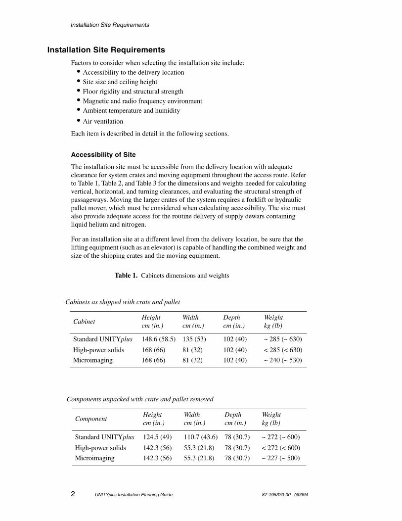
The installation site must be accessible from the delivery location with adequate clearance for system crates and moving equipment throughout the access route. Refer to Table 1, Table 2, and Table 3 for the dimensions and weights needed for calculating vertical, horizontal, and turning clearances, and evaluating the structural strength of passageways. Moving the larger crates of the system requires a forklift or hydraulic pallet mover, which must be considered when calculating accessibility. The site must also provide adequate access for the routine delivery of supply dewars containing liquid helium and nitrogen.
For an installation site at a different level from the delivery location, be sure that the lifting equipment (such as an elevator) is capable of handling the combined weight and size of the shipping crates and the moving equipment.
Table 1. Cabinets dimensions and weights
Cabinets as shipped with crate and pallet
CabinetHeightcm (in.)
Widthcm (in.)
Depthcm (in.)
Weightkg (lb)
Standard UNITYplus 148.6 (58.5) 135 (53) 102 (40) ~ 285 (~ 630)
High-power solids 168 (66) 81 (32) 102 (40) < 285 (< 630)
Microimaging 168 (66) 81 (32) 102 (40) ~ 240 (~ 530)
Components unpacked with crate and pallet removed
ComponentHeightcm (in.)
Widthcm (in.)
Depthcm (in.)
Weightkg (lb)
Standard UNITYplus 124.5 (49) 110.7 (43.6) 78 (30.7) ~ 272 (~ 600)
High-power solids 142.3 (56) 55.3 (21.8) 78 (30.7) < 272 (< 600)
Microimaging 142.3 (56) 55.3 (21.8) 78 (30.7) ~ 227 (~ 500)
Installation Site Requirements
87-195320-00 G0994 UNITYplus Installation Planning Guide
3
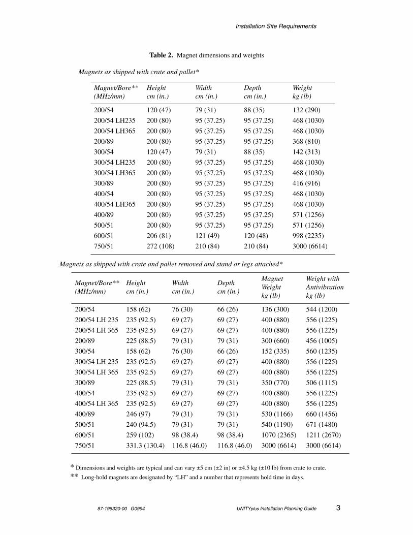
Table 2. Magnet dimensions and weights
Magnets as shipped with crate and pallet*
Magnet/Bore**(MHz/mm)
Height cm (in.)
Widthcm (in.)
Depthcm (in.)
Weightkg (lb)
200/54 120 (47) 79 (31) 88 (35) 132 (290)
200/54 LH235 200 (80) 95 (37.25) 95 (37.25) 468 (1030)
200/54 LH365 200 (80) 95 (37.25) 95 (37.25) 468 (1030)
200/89 200 (80) 95 (37.25) 95 (37.25) 368 (810)
300/54 120 (47) 79 (31) 88 (35) 142 (313)
300/54 LH235 200 (80) 95 (37.25) 95 (37.25) 468 (1030)
300/54 LH365 200 (80) 95 (37.25) 95 (37.25) 468 (1030)
300/89 200 (80) 95 (37.25) 95 (37.25) 416 (916)
400/54 200 (80) 95 (37.25) 95 (37.25) 468 (1030)
400/54 LH365 200 (80) 95 (37.25) 95 (37.25) 468 (1030)
400/89 200 (80) 95 (37.25) 95 (37.25) 571 (1256)
500/51 200 (80) 95 (37.25) 95 (37.25) 571 (1256)
600/51 206 (81) 121 (49) 120 (48) 998 (2235)
750/51 272 (108) 210 (84) 210 (84) 3000 (6614)
Magnets as shipped with crate and pallet removed and stand or legs attached*
Magnet/Bore**(MHz/mm)
Heightcm (in.)
Widthcm (in.)
Depthcm (in.)
MagnetWeightkg (lb)
Weight with Antivibrationkg (lb)
200/54 158 (62) 76 (30) 66 (26) 136 (300) 544 (1200)
200/54 LH 235 235 (92.5) 69 (27) 69 (27) 400 (880) 556 (1225)
200/54 LH 365 235 (92.5) 69 (27) 69 (27) 400 (880) 556 (1225)
200/89 225 (88.5) 79 (31) 79 (31) 300 (660) 456 (1005)
300/54 158 (62) 76 (30) 66 (26) 152 (335) 560 (1235)
300/54 LH 235 235 (92.5) 69 (27) 69 (27) 400 (880) 556 (1225)
300/54 LH 365 235 (92.5) 69 (27) 69 (27) 400 (880) 556 (1225)
300/89 225 (88.5) 79 (31) 79 (31) 350 (770) 506 (1115)
400/54 235 (92.5) 69 (27) 69 (27) 400 (880) 556 (1225)
400/54 LH 365 235 (92.5) 69 (27) 69 (27) 400 (880) 556 (1225)
400/89 246 (97) 79 (31) 79 (31) 530 (1166) 660 (1456)
500/51 240 (94.5) 79 (31) 79 (31) 540 (1190) 671 (1480)
600/51 259 (102) 98 (38.4) 98 (38.4) 1070 (2365) 1211 (2670)
750/51 331.3 (130.4) 116.8 (46.0) 116.8 (46.0) 3000 (6614) 3000 (6614)
* Dimensions and weights are typical and can vary ±5 cm (±2 in) or ±4.5 kg (±10 lb) from crate to crate.
** Long-hold magnets are designated by “LH” and a number that represents hold time in days.
Installation Site Requirements
4
UNITYplus Installation Planning Guide 87-195320-00 G0994
If it is not possible to gain access to the installation site unless the system is uncrated, contact a Varian service representative for further instructions. Do not uncrate the system except with direct instructions from an authorized service representative.
Site Size
The site must be large enough to allow free access to all sides of the system and magnet for operation, maintenance, and cryogenic service. Table 1, Table 2, and Table 3 list the dimensions of the system components, and “Appendix D. System Cable Lengths and Room Layouts” on page 54, contains floor plans for the NMR laboratory area or room. The plans are suggestions and not specifications.
All cabinets have casters for easy movement, which allows the system to be placed in a location as small as that illustrated in the section “Minimum Space for 200/51 or 300/51 System Without Options” in Appendix D on page 54, as long as sufficient space exists for the cabinets to be moved to provide for access to all sides. For comfort and convenience, however, and to provide space for an automatic sample changer or other options, the larger layouts shown in Appendix D on page 54 are highly recommended. The minimum dimensions do
not
include compensation for external magnetic and rf interference that may be present. Each individual site must be analyzed to ensure optimum system performance.
Table 3. System accessories dimensions and weights
SMS Autosampler system
ConfigurationHeightcm (in.)
Widthcm (in.)
Depthcm (in.)
Weightkg (lb)
With crate and pallet 23 (50)
Crate and pallet removed 71 (28) 34.3 (13.5) 34.3 (13.5) 17 (38)
UNITYplus work table
ConfigurationHeightcm (in.)
Widthcm (in.)
Depthcm (in.)
Weightkg (lb)
In carton 31 (12) 198 (78) 91 (36) 53 (117)
Assembled 67 (26.5) 183 (72) 76 (30) 48 (107)
Ultra•nmr Shims accessory
ItemHeightcm (in.)
Widthcm (in.)
Depthcm (in.)
Weightkg (lb)
Interface (HIM) Box 13 (5) 27 (11) 20 (8)
Power Supply 86 (34) 55.5 (22) 78.5 (31) 68 (150)
Installation Site Requirements
87-195320-00 G0994 UNITYplus Installation Planning Guide 5
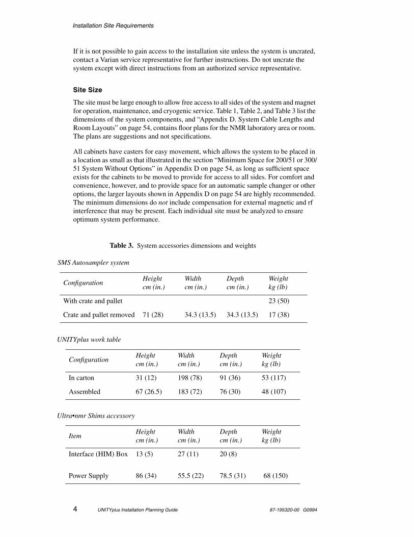
Ceiling Height Requirements
The ceiling must provide sufficient headroom to insert the liquid helium transfer tube into the magnet dewar and the storage dewar. The height of the ceiling (or that part of the ceiling located directly above the magnet) without obstructions such as lighting and heating ducts must be equal to or greater than the minimum heights in Table 4. On 600-MHz magnets, minimum ceiling height includes a flexible helium level sensor probe.
These ceiling minimums allow enough headroom to insert the standard helium flutter tube and refill transfer tubes into the magnet dewar. They also allow use of the standard power stick for running up the magnet field. If one of the larger capacity liquid helium storage dewars is used with the magnet, however, additional ceiling clearance may be necessary. In general, the ceiling height must be at least twice the height of liquid helium storage dewar above the floor. Oxford magnets can be provided with optional hinged top-loading components that reduces the minimum ceiling height requirements. Contact Oxford for details.
Most of the antivibration (vibration isolation) systems add nothing to the ceiling height requirements, with the exception of the 200/54 and 300/54 magnets when placed on an antivibration table system. For these cases add 20 cm (8 in) to the ceiling height requirements.
Table 4. Ceiling minimum height
Magnet/Bore (MHz/mm)
Ceiling Minimumcm (in.)
With Optional Helium Level Sensor, cm (in.)
200/54 252 (99) Not applicable
200/54 LH235 321 (126.5) 365 cm (144 in)
200/54 LH365 321 (126.5) 365 cm (144 in)
200/89 311 (122.5) 355 cm (140 in)
300/54 252 (99) Not applicable
300/54 LH235 321 (126.5) 365 cm (144 in)
300/54 LH365 321 (126.5) 365 cm (144 in)
300/89 311 (122.5) 355 cm (140 in)
400/54 321 (126.5) 365 cm (144 in)
400/54 LH365 321 (126.5) 365 cm (144 in)
400/89 321 (126.5) 344 cm (135.5 in)
500/51 311 (122.5) 345 cm (136 in)
600/51 334 (131.2) Includes flexible helium level probe
750/51 400 (157.5)
Installation Site Requirements
6 UNITYplus Installation Planning Guide 87-195320-00 G0994
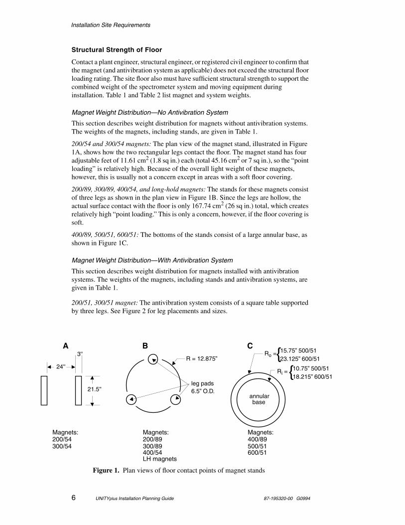
Structural Strength of Floor
Contact a plant engineer, structural engineer, or registered civil engineer to confirm that the magnet (and antivibration system as applicable) does not exceed the structural floor loading rating. The site floor also must have sufficient structural strength to support the combined weight of the spectrometer system and moving equipment during installation. Table 1 and Table 2 list magnet and system weights.
Magnet Weight Distribution—No Antivibration System
This section describes weight distribution for magnets without antivibration systems. The weights of the magnets, including stands, are given in Table 1.
200/54 and 300/54 magnets: The plan view of the magnet stand, illustrated in Figure 1A, shows how the two rectangular legs contact the floor. The magnet stand has four adjustable feet of 11.61 cm2 (1.8 sq in.) each (total 45.16 cm2 or 7 sq in.), so the “point loading” is relatively high. Because of the overall light weight of these magnets, however, this is usually not a concern except in areas with a soft floor covering.
200/89, 300/89, 400/54, and long-hold magnets: The stands for these magnets consist of three legs as shown in the plan view in Figure 1B. Since the legs are hollow, the actual surface contact with the floor is only 167.74 cm2 (26 sq in.) total, which creates relatively high “point loading.” This is only a concern, however, if the floor covering is soft.
400/89, 500/51, 600/51: The bottoms of the stands consist of a large annular base, as shown in Figure 1C.
Magnet Weight Distribution—With Antivibration System
This section describes weight distribution for magnets installed with antivibration systems. The weights of the magnets, including stands and antivibration systems, are given in Table 1.
200/51, 300/51 magnet: The antivibration system consists of a square table supported by three legs. See Figure 2 for leg placements and sizes.
3''
24''
21.5''
A B C
Ri = 10.75” 500/5118.215” 600/51{
Ro = 15.75” 500/5123.125” 600/51{
annularbase
R = 12.875”
leg pads6.5” O.D.
Figure 1. Plan views of floor contact points of magnet stands
Magnets:200/89300/89
Magnets:200/54300/54
Magnets:400/89500/51
400/54 600/51LH magnets
Installation Site Requirements
87-195320-00 G0994 UNITYplus Installation Planning Guide 7
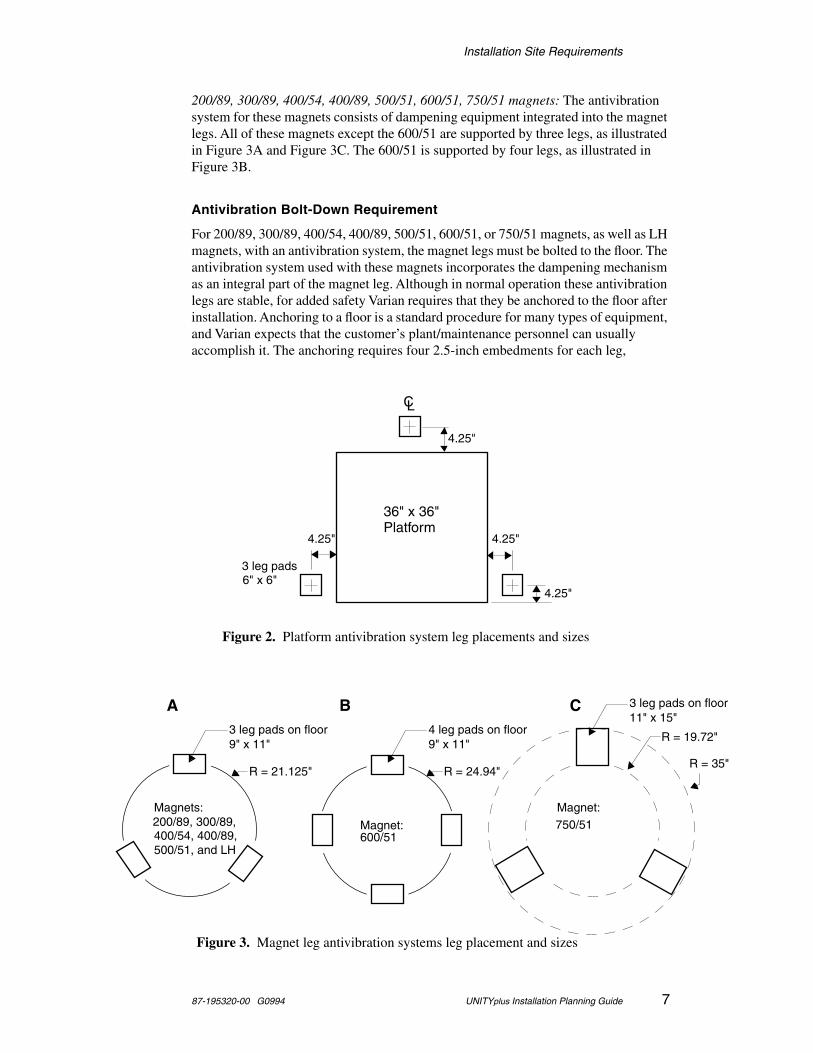
200/89, 300/89, 400/54, 400/89, 500/51, 600/51, 750/51 magnets: The antivibration system for these magnets consists of dampening equipment integrated into the magnet legs. All of these magnets except the 600/51 are supported by three legs, as illustrated in Figure 3A and Figure 3C. The 600/51 is supported by four legs, as illustrated in Figure 3B.
Antivibration Bolt-Down Requirement
For 200/89, 300/89, 400/54, 400/89, 500/51, 600/51, or 750/51 magnets, as well as LH magnets, with an antivibration system, the magnet legs must be bolted to the floor. The antivibration system used with these magnets incorporates the dampening mechanism as an integral part of the magnet leg. Although in normal operation these antivibration legs are stable, for added safety Varian requires that they be anchored to the floor after installation. Anchoring to a floor is a standard procedure for many types of equipment, and Varian expects that the customer’s plant/maintenance personnel can usually accomplish it. The anchoring requires four 2.5-inch embedments for each leg,
CL
36" x 36"Platform
4.25"
4.25"4.25"
4.25"
3 leg pads6" x 6"
Figure 2. Platform antivibration system leg placements and sizes
R = 21.125"
3 leg pads on floor9" x 11"
4 leg pads on floor9" x 11"
R = 24.94"
A B
Magnets:
400/54, 400/89,500/51, and LH
Figure 3. Magnet leg antivibration systems leg placement and sizes
200/89, 300/89, Magnet:600/51
R = 19.72"
3 leg pads on floor11" x 15"
C
Magnet:750/51
R = 35"
Installation Site Requirements
8 UNITYplus Installation Planning Guide 87-195320-00 G0994
anchored using 0.5 inch bolts. Details are provided in the Antivibration System Installation Manual; this note is provided for information purposes only.
Floor Vibration Requirements
The floor must be sufficiently rigid to reduce the vibration from adjacent dynamic loads to a negligible level, defined as no single peak vibration greater than 20 µg (for 400-, 500-, 600-, 750-MHz and long-hold magnets) or 100 µg (200- and 300-MHz magnets) acceleration from 0 to 100 Hz.
Measurement is made with an Ono Sokki Model CF 200 field FFT analyzer (or a Hewlett-Packard Model 3561A signal analyzer or equivalent) using 16 rms time averages and with a seismic accelerometer with 10 V/g sensitivity (Wilcoxen Model 731 or equivalent).
Magnetic Environment
The site must have a minimum of environmental magnetic fields. Common sources of magnetic interference are fluctuating loads on adjacent power lines, radio or television transmissions, heavy-duty transformers, elevator motors, and similar electromagnetic devices. Allow a separation of at least 4.6 m (15 ft) between the magnet and other high-field electromagnets, elevators, or forklift trucks.
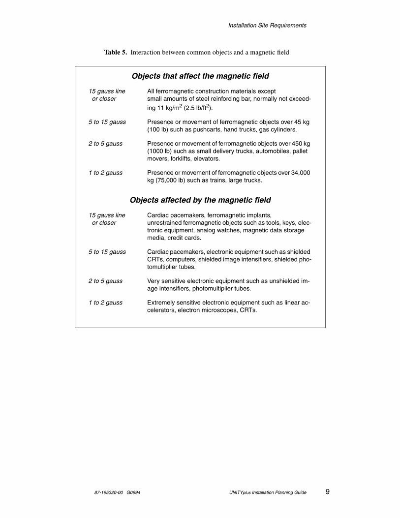
Similar separation distances must also be maintained between the magnet and anything that can cause a detrimental effect on the field homogeneity or the structural integrity of the magnet. Conditions that could interfere with the magnet include (but by no means limited to) a wall with metal sheathing or steel studding, a concrete support column with steel reinforcing bars, and a storage area containing steel dewars for cryogenic storage. Each site must be carefully analyzed to ensure optimum performance of the system. See Table 5 for examples of objects that affect or are affected by the magnetic field.
The CRT in color monitors needs to be degaussed in magnetic fields above 1 to 2 gauss. Above 5 gauss, color monitors may need additional shielding to prevent display distortion. Sun computers and peripherals are also affected by the magnetic field; refer to “Computer Preparation” on page 30 for a discussion of magnetic field considerations.
WARNING Cardiac pacemaker wearers must remain more than 4.5 m or 15 ft (6.1 m or 25 ft for the 750/51) away in all directions from the magnet until safety is clearly established. An NMR superconducting magnet generates strong magnetic and electromagnetic fields that can inhibit operation of some cardiac pacemakers, resulting in death or serious injury to the user. Consult the pacemaker user's manual, contact the manufacturer, or confer with a physician to determine the effect on a specific pacemaker. Varian provides signs with each system to warn pacemaker wearers of this hazard. Post the signs at least 4.5 m or 15 ft (6.1m or 25 ft for the 750/51) from the magnet.
Installation Site Requirements
87-195320-00 G0994 UNITYplus Installation Planning Guide 9
Objects that affect the magnetic field
15 gauss line All ferromagnetic construction materials except or closer small amounts of steel reinforcing bar, normally not exceed-
ing 11 kg/m2 (2.5 lb/ft2).
5 to 15 gauss Presence or movement of ferromagnetic objects over 45 kg (100 lb) such as pushcarts, hand trucks, gas cylinders.
2 to 5 gauss Presence or movement of ferromagnetic objects over 450 kg (1000 lb) such as small delivery trucks, automobiles, pallet movers, forklifts, elevators.
1 to 2 gauss Presence or movement of ferromagnetic objects over 34,000 kg (75,000 lb) such as trains, large trucks.
Objects affected by the magnetic field
15 gauss line Cardiac pacemakers, ferromagnetic implants, or closer unrestrained ferromagnetic objects such as tools, keys, elec-
tronic equipment, analog watches, magnetic data storage media, credit cards.
5 to 15 gauss Cardiac pacemakers, electronic equipment such as shielded CRTs, computers, shielded image intensifiers, shielded pho-tomultiplier tubes.
2 to 5 gauss Very sensitive electronic equipment such as unshielded im-age intensifiers, photomultiplier tubes.
1 to 2 gauss Extremely sensitive electronic equipment such as linear ac-celerators, electron microscopes, CRTs.
Table 5. Interaction between common objects and a magnetic field
Installation Site Requirements
10 UNITYplus Installation Planning Guide 87-195320-00 G0994
Safety Hazards of Strong Magnetic Fields
The potential safety hazards of strong magnetic fields to devices such as certain pacemakers must be understood and planned for. A set of plots indicating the magnitude of the stray fields for each type of magnet is included in Appendix B on page 41. These plots show typical levels of stray field. Actual levels may vary and should be checked after a particular magnet has been installed.
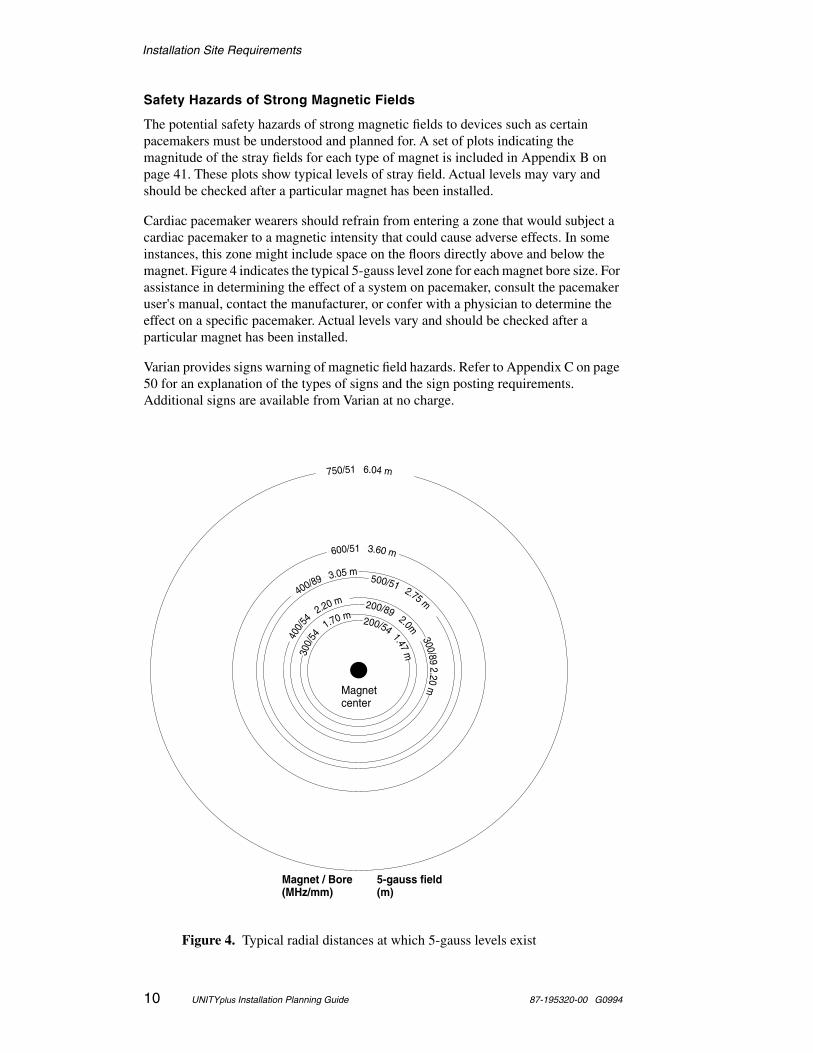
Cardiac pacemaker wearers should refrain from entering a zone that would subject a cardiac pacemaker to a magnetic intensity that could cause adverse effects. In some instances, this zone might include space on the floors directly above and below the magnet. Figure 4 indicates the typical 5-gauss level zone for each magnet bore size. For assistance in determining the effect of a system on pacemaker, consult the pacemaker user's manual, contact the manufacturer, or confer with a physician to determine the effect on a specific pacemaker. Actual levels vary and should be checked after a particular magnet has been installed.
Varian provides signs warning of magnetic field hazards. Refer to Appendix C on page 50 for an explanation of the types of signs and the sign posting requirements. Additional signs are available from Varian at no charge.
Figure 4. Typical radial distances at which 5-gauss levels exist
Magnet center
Magnet / Bore(MHz/mm)
5-gauss field (m)
750/51 6.04 m
600/51 3.60 m
300/
54
1.70 m
400/89 3.05 m500/51 2.75 m
400/5
42.20 m
300/892.20
m
200/892.0m200/54
1.47m
Installation Site Requirements
87-195320-00 G0994 UNITYplus Installation Planning Guide 11
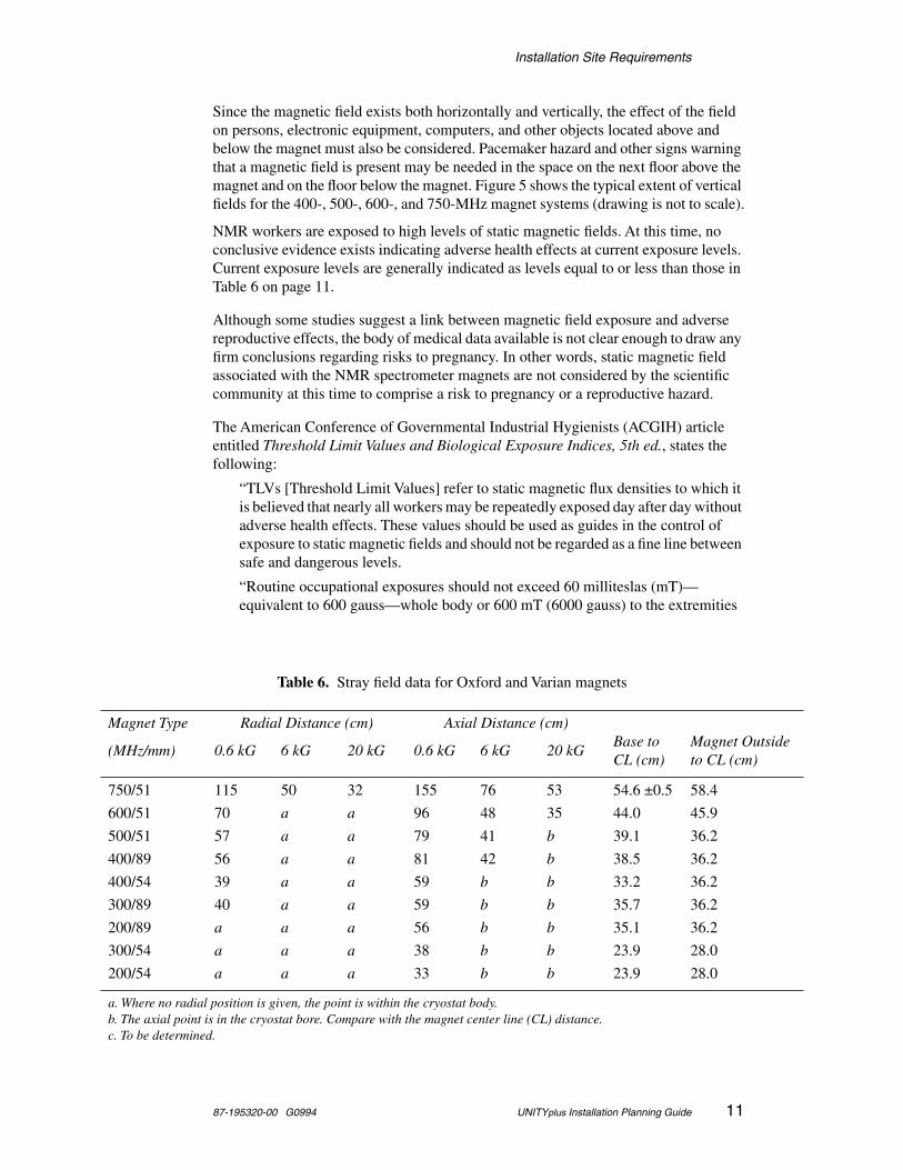
Since the magnetic field exists both horizontally and vertically, the effect of the field on persons, electronic equipment, computers, and other objects located above and below the magnet must also be considered. Pacemaker hazard and other signs warning that a magnetic field is present may be needed in the space on the next floor above the magnet and on the floor below the magnet. Figure 5 shows the typical extent of vertical fields for the 400-, 500-, 600-, and 750-MHz magnet systems (drawing is not to scale).
NMR workers are exposed to high levels of static magnetic fields. At this time, no conclusive evidence exists indicating adverse health effects at current exposure levels. Current exposure levels are generally indicated as levels equal to or less than those in Table 6 on page 11.
Although some studies suggest a link between magnetic field exposure and adverse reproductive effects, the body of medical data available is not clear enough to draw any firm conclusions regarding risks to pregnancy. In other words, static magnetic field associated with the NMR spectrometer magnets are not considered by the scientific community at this time to comprise a risk to pregnancy or a reproductive hazard.
The American Conference of Governmental Industrial Hygienists (ACGIH) article entitled Threshold Limit Values and Biological Exposure Indices, 5th ed., states the following:
“TLVs [Threshold Limit Values] refer to static magnetic flux densities to which it is believed that nearly all workers may be repeatedly exposed day after day without adverse health effects. These values should be used as guides in the control of exposure to static magnetic fields and should not be regarded as a fine line between safe and dangerous levels.
“Routine occupational exposures should not exceed 60 milliteslas (mT)—equivalent to 600 gauss—whole body or 600 mT (6000 gauss) to the extremities
Table 6. Stray field data for Oxford and Varian magnets
Magnet Type Radial Distance (cm) Axial Distance (cm)
(MHz/mm) 0.6 kG 6 kG 20 kG 0.6 kG 6 kG 20 kGBase to CL (cm)
Magnet Outside to CL (cm)
750/51 115 50 32 155 76 53 54.6 ±0.5 58.4
600/51 70 a a 96 48 35 44.0 45.9
500/51 57 a a 79 41 b 39.1 36.2
400/89 56 a a 81 42 b 38.5 36.2
400/54 39 a a 59 b b 33.2 36.2
300/89 40 a a 59 b b 35.7 36.2
200/89 a a a 56 b b 35.1 36.2
300/54 a a a 38 b b 23.9 28.0
200/54 a a a 33 b b 23.9 28.0
a. Where no radial position is given, the point is within the cryostat body.b. The axial point is in the cryostat bore. Compare with the magnet center line (CL) distance.c. To be determined.

Installation Site Requirements
12 UNITYplus Installation Planning Guide 87-195320-00 G0994
Figure 5. Typical vertical stray fields for 400/54, 500/51, 600/51, and 750/51 magnets
3.45 m (500) Typical 5-gauss
vertical zone
Typical 10-gauss vertical zone
7.60 m (750)4.55 m (600)
2.80 m (400)
2.70 m (500)
6.04 m (750)3.60 m (600)
2.24 m (400)
Magnet room floor
Centerline to floor 400/54 1.16 m500/51 1.24 m600/51 1.35 m750/51 1.38 m
Installation Site Requirements
87-195320-00 G0994 UNITYplus Installation Planning Guide 13
on a daily [8 hour], time-weighted average basis. A flux density of 2 teslas (20,000 gauss) is recommended as a ceiling value.”
Radio-Frequency Environment
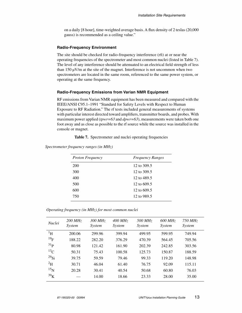
The site should be checked for radio-frequency interference (rfi) at or near the operating frequencies of the spectrometer and most common nuclei (listed in Table 7). The level of any interference should be attenuated to an electrical field strength of less than 150 µV/m at the site of the magnet. Interference is not uncommon when two spectrometers are located in the same room, referenced to the same power system, or operating at the same frequency.
Radio-Frequency Emissions from Varian NMR Equipment
RF emissions from Varian NMR equipment has been measured and compared with the IEEE/ANSI C95.1–1991 “Standard for Safety Levels with Respect to Human Exposure to RF Radiation.” The rf tests included general measurements of systems with particular interest directed toward amplifiers, transmitter boards, and probes. With maximum power applied (tpwr=63 and dpwr=63), measurements were taken both one foot away and as close as possible to the rf source while the source was installed in the console or magnet.
Table 7. Spectrometer and nuclei operating frequencies
Spectrometer frequency ranges (in MHz)
Proton Frequency Frequency Ranges
200 12 to 309.5
300 12 to 309.5
400 12 to 489.5
500 12 to 609.5
600 12 to 609.5
750 12 to 989.5
Operating frequency (in MHz) for most common nuclei
Nuclei200 MHzSystem
300 MHzSystem
400 MHz System
500 MHzSystem
600 MHzSystem
750 MHzSystem
1H 200.06 299.96 399.94 499.95 599.95 749.9419F 188.22 282.20 376.29 470.39 564.45 705.5631P 80.98 121.42 161.90 202.39 242.85 303.5613C 50.31 75.43 100.58 125.73 150.87 188.5929Si 39.75 59.59 79.46 99.33 119.20 148.982H 30.71 46.04 61.40 76.75 92.09 115.1115N 20.28 30.41 40.54 50.68 60.80 76.0339K — 14.00 18.66 23.33 28.00 35.00
Installation Site Requirements
14 UNITYplus Installation Planning Guide 87-195320-00 G0994
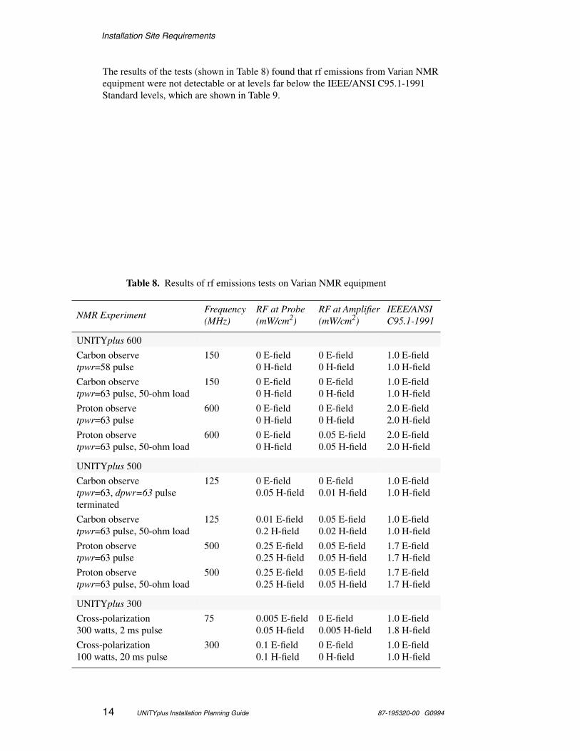
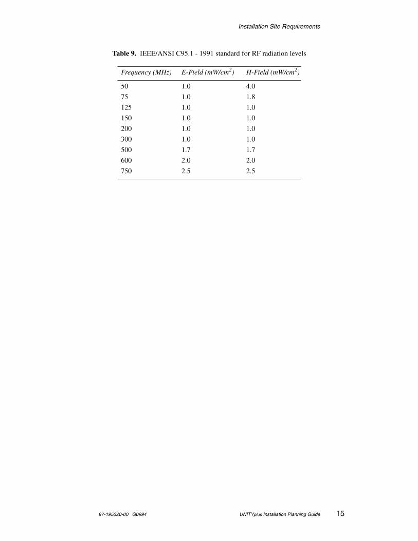
The results of the tests (shown in Table 8) found that rf emissions from Varian NMR equipment were not detectable or at levels far below the IEEE/ANSI C95.1-1991 Standard levels, which are shown in Table 9.
Table 8. Results of rf emissions tests on Varian NMR equipment
NMR ExperimentFrequency (MHz)
RF at Probe (mW/cm2)
RF at Amplifier (mW/cm2)
IEEE/ANSI C95.1-1991
UNITYplus 600
Carbon observetpwr=58 pulse
150 0 E-field0 H-field
0 E-field0 H-field
1.0 E-field1.0 H-field
Carbon observetpwr=63 pulse, 50-ohm load
150 0 E-field0 H-field
0 E-field0 H-field
1.0 E-field1.0 H-field
Proton observetpwr=63 pulse
600 0 E-field0 H-field
0 E-field0 H-field
2.0 E-field2.0 H-field
Proton observetpwr=63 pulse, 50-ohm load
600 0 E-field0 H-field
0.05 E-field0.05 H-field
2.0 E-field2.0 H-field
UNITYplus 500
Carbon observetpwr=63, dpwr=63 pulseterminated
125 0 E-field0.05 H-field
0 E-field0.01 H-field
1.0 E-field1.0 H-field
Carbon observetpwr=63 pulse, 50-ohm load
125 0.01 E-field0.2 H-field
0.05 E-field0.02 H-field
1.0 E-field1.0 H-field
Proton observetpwr=63 pulse
500 0.25 E-field0.25 H-field
0.05 E-field0.05 H-field
1.7 E-field1.7 H-field
Proton observetpwr=63 pulse, 50-ohm load
500 0.25 E-field0.25 H-field
0.05 E-field0.05 H-field
1.7 E-field1.7 H-field
UNITYplus 300
Cross-polarization300 watts, 2 ms pulse
75 0.005 E-field0.05 H-field
0 E-field0.005 H-field
1.0 E-field1.8 H-field
Cross-polarization100 watts, 20 ms pulse
300 0.1 E-field0.1 H-field
0 E-field0 H-field
1.0 E-field1.0 H-field
Installation Site Requirements
87-195320-00 G0994 UNITYplus Installation Planning Guide 15
Table 9. IEEE/ANSI C95.1 - 1991 standard for RF radiation levels
Frequency (MHz) E-Field (mW/cm2) H-Field (mW/cm2)
50 1.0 4.0
75 1.0 1.8
125 1.0 1.0
150 1.0 1.0
200 1.0 1.0
300 1.0 1.0
500 1.7 1.7
600 2.0 2.0
750 2.5 2.5
Installation Site Requirements
16 UNITYplus Installation Planning Guide 87-195320-00 G0994
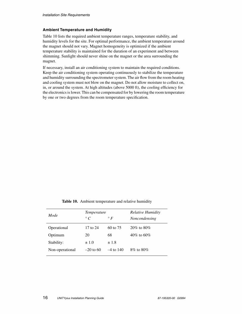
Ambient Temperature and Humidity
Table 10 lists the required ambient temperature ranges, temperature stability, and humidity levels for the site. For optimal performance, the ambient temperature around the magnet should not vary. Magnet homogeneity is optimized if the ambient temperature stability is maintained for the duration of an experiment and between shimming. Sunlight should never shine on the magnet or the area surrounding the magnet.
If necessary, install an air conditioning system to maintain the required conditions. Keep the air conditioning system operating continuously to stabilize the temperature and humidity surrounding the spectrometer system. The air flow from the room heating and cooling system must not blow on the magnet. Do not allow moisture to collect on, in, or around the system. At high altitudes (above 5000 ft), the cooling efficiency for the electronics is lower. This can be compensated for by lowering the room temperature by one or two degrees from the room temperature specification.
Table 10. Ambient temperature and relative humidity
ModeTemperature Relative Humidity
° C ° F Noncondensing
Operational 17 to 24 60 to 75 20% to 80%
Optimum 20 68 40% to 60%
Stability: ± 1.0 ± 1.8
Non-operational –20 to 60 –4 to 140 8% to 80%

Installation Site Requirements
87-195320-00 G0994 UNITYplus Installation Planning Guide 17
Ventilation
Air ventilation must be adequate to displace the liquid helium gas during a quench, especially when using any type of volatile liquid for variable temperature experiments. Consult with a safety engineer on this subject. See also Table 11, which lists the amount of liquid helium for each magnet.
Maximum Altitude
The maximum altitude during operation is 2440 m (8000 ft). The maximum during storage or transport is 9100 m (30,000 ft).
Table 11. Liquid helium displacement for room ventilation considerations
Magnet/Bore(MHz/mm)
LHe Maximum Volume (liters)
750/51 440
600/51 138
500/51 68
400/89 81
400/54 LH365 74
400/54 74
300/89 65
300/54 LH365 74
300/54 LH235 74
300/54 30
200/89 65
200/54 LH365 74
200/54 LH235 74
200/54 30
Installation Site Preparation
18 UNITYplus Installation Planning Guide 87-195320-00 G0994
Installation Site Preparation
Verify the configuration with a Varian representative before designing the room layout. Site preparation must conform with federal, state, and local codes, which take precedence over recommendations in this guide. Approval by a building inspector may be necessary.
Line Voltage Variation
UNITYplus spectrometers require one line tap at 220 Vac, single phase.
Measure and record the ac line voltage for 48 hours using a suitable power line analyzer, such as the BMI Model 4800 or equivalent. Provide a copy for the Varian installation engineer. Requirements are the following:
• Long-term voltage variations (slow average) do not exceed 7% of nominal line tap voltages.
• Short-term voltage variations (sag or surge), with a duration between several milliseconds and several seconds, do not exceed 10% of nominal line tap voltage.
• Line transients (impulse) with a duration between 1 µs and 800 µs, not to exceed 50 V peak above or below nominal line tap voltage. These transients must be measured at the power plug with a load connected that draws the same power as the spectrometer.
• AC line frequency does not vary by more than +0.5 to –1.0 Hz.
The purchase of a line conditioner and regulator is strongly recommended. By providing protection against transients and improving line regulation, total system “up-time” will improve and the electronic components within the system will last longer. In many locations, a good power conditioning system will pay for itself within a few years. Contact a local power consultant for suitable equipment in your area.
Uninterrupted Power Supply (UPS)
If your site experiences frequent and short (less than 10 minutes) power outages, you may want to consider a UPS. UPS systems are limited in how long they can supply power when house power is out. Consider the placement of a UPS when planning your lab. If you want to use one UPS, it must have output for 208 Vac and 120 Vac and it must be placed such that both the NMR console and the host computer can use it.
Electrical Outlets
Host Computer and Peripherals. The host workstation and accessories require a minimum of six 120 Vac, single-phase power outlets. Locations with ac voltages over 132 Vac should check with their local Varian service center for power outlet requirements. Locations with ac voltages over 125 Vac might need at least one step-down transformer. To minimize ground loop interference, these outlets should all be on the same 20 A service. It is strongly recommended that surge protection be provided.
Standard Two-Cabinet System. The standard two-cabinet system requires a dedicated single-phase, continuous-duty 220 Vac (±7%), 50/60 Hz power line with 20 A minimum service. Terminate this line within 3 m (10 ft) of the left side (looking from the rear) of the standard cabinet with a fused, quick-disconnect switch box or circuit
Installation Site Preparation
87-195320-00 G0994 UNITYplus Installation Planning Guide 19
breaker. Run a separate, insulated, low-resistance earth ground to the main electrical service entrance ground.
Solid-State NMR Modules. No extra electrical services are required for solids modules that do not require the third cabinet, such as CP/MAS. Solids modules that require the third cabinet, such as Wideline and CRAMPS/Multipulse, require an additional 208/220/240 Vac single-phase, 30 A dedicated line. A spectrometer system with complete liquids and solids capability (CP/MAS, Wideline, and CRAMPS/Multipulse) requires an electrical supply with one 220 Vac single-phase 20 A outlet and for the standard cabinet and one 208/220/240 Vac single-phase 30 A outlet for the high-power solids cabinet.
VT CP/MAS Option requires a dedicated, single-phase, continuous-duty 50/60 Hz power line as shown in the following table. In addition, the customer must supply a 3-prong polarized plug compatible with the site voltage.
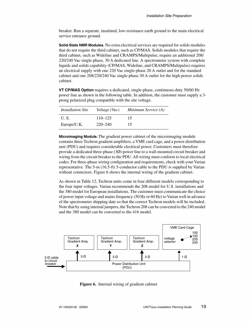
Microimaging Module. The gradient power cabinet of the microimaging module contains three Techron gradient amplifiers, a VME card cage, and a power distribution unit (PDU) and requires considerable electrical power. Customers must therefore provide a dedicated three-phase (3Ø) power line to a wall-mounted circuit breaker and wiring from the circuit breaker to the PDU. All wiring must conform to local electrical codes. For three-phase wiring configuration and requirements, check with your Varian representative. The 5-m (16.5-ft) 5-conductor cable to the PDU is supplied by Varian without connectors. Figure 6 shows the internal wiring of the gradient cabinet.
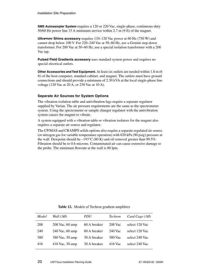
As shown in Table 12, Techron units come in four different models corresponding to the four input voltages. Varian recommends the 208 model for U.S. installations and the 380 model for European installations. The customer must communicate the choice of power input voltage and mains frequency (50 Hz or 60 Hz) to Varian well in advance of the spectrometer shipping date so that the correct Techron models will be included. Note that by using internal jumpers, the Techron 208 can be converted to the 240 model and the 380 model can be converted to the 416 model.
Installation Site Voltage (Vac) Minimum Service (A)
U. S. 110–125 15
Europe/U.K. 220–240 15
Figure 6. Internal wiring of gradient cabinet
VME Card Cage
3 Ø cableto circuitbreaker Power Distribution Unit
(PDU)
1 Ø3 Ø3 Ø 3 Ø
TechronGradient Amp.
TechronGradient Amp.
TechronGradient Amp.
X Y Z
100120220240
voltageselector
Installation Site Preparation
20 UNITYplus Installation Planning Guide 87-195320-00 G0994
SMS Autosampler System requires a 120 or 220 Vac, single-phase, continuous-duty 50/60 Hz power line 15 A minimum service within 2.7 m (9 ft) of the magnet.
Ultra•nmr Shims accessory requires 110–120 Vac power at 60 Hz (750 W) and cannot drop below 100 V. For 220–240 Vac at 50–60 Hz, use a Gemini step-down transformer. For 200 Vac at 50–60 Hz, use a special isolation transformer with a 200 Vac tap.
Pulsed Field Gradients accessory uses standard system power and requires no special electrical outlets.
Other Accessories and Test Equipment. At least six outlets are needed within 1.8 m (6 ft) of the host computer, standard cabinet, and magnet. The outlets must have ground connections and should provide a minimum of 2.30 kVA at the local single-phase line voltage (120 Vac at 20 A, or 230 Vac at 10 A).
Separate Air Sources for System Options
The vibration isolation table and antivibration legs require a separate regulator supplied by Varian. The air pressure requirements are the same as the spectrometer system. Using the spectrometer or sample changer regulator with the antivibration system causes the magnet to vibrate.
A system equipped with a vibration table or vibration isolators for the magnet also requires a separate air source and regulator.
The CP/MAS and CRAMPS solids options also require a separate regulated air source (or nitrogen gas for variable temperature operation) with 620 kPa (90 psig) pressure at the wall. Dewpoint should be –193°C (80 K) and oil removal greater than 99.5%. Filtration should be to 0.6 microns. Contaminated air can cause extensive damage to the probe. The minimum flowrate at the wall is 80 lpm.
Table 12. Models of Techron gradient amplifiers
Model Wall (3Ø) PDU Techron Card Cage (1Ø)
208 208 Vac, 60 amp 60 A breaker 208 Vac select 120 Vac
240 240 Vac, 60 amp 60 A breaker 240 Vac select 120 Vac
380 380 Vac, 30 amp 30 A breaker 380 Vac select 240 Vac
416 416 Vac, 30 amp 30 A breaker 416 Vac select 240 Vac
Installation Site Preparation
87-195320-00 G0994 UNITYplus Installation Planning Guide 21
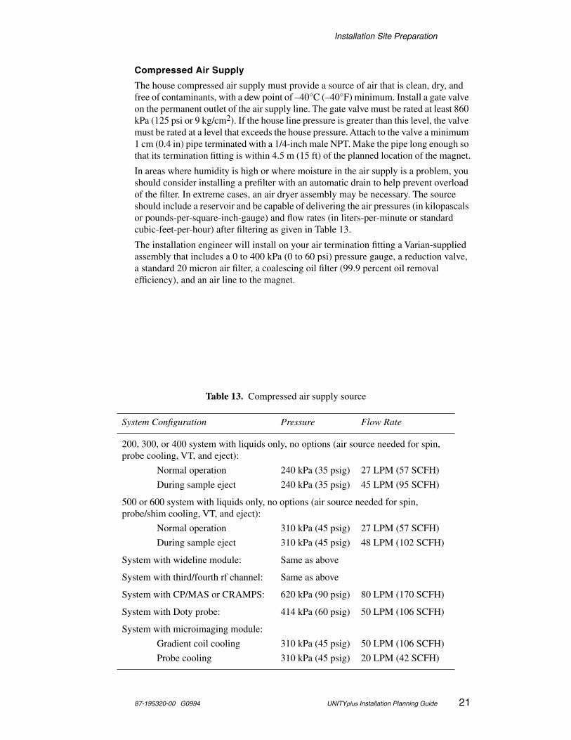
Compressed Air Supply
The house compressed air supply must provide a source of air that is clean, dry, and free of contaminants, with a dew point of –40°C (–40°F) minimum. Install a gate valve on the permanent outlet of the air supply line. The gate valve must be rated at least 860 kPa (125 psi or 9 kg/cm2). If the house line pressure is greater than this level, the valve must be rated at a level that exceeds the house pressure. Attach to the valve a minimum 1 cm (0.4 in) pipe terminated with a 1/4-inch male NPT. Make the pipe long enough so that its termination fitting is within 4.5 m (15 ft) of the planned location of the magnet.
In areas where humidity is high or where moisture in the air supply is a problem, you should consider installing a prefilter with an automatic drain to help prevent overload of the filter. In extreme cases, an air dryer assembly may be necessary. The source should include a reservoir and be capable of delivering the air pressures (in kilopascals or pounds-per-square-inch-gauge) and flow rates (in liters-per-minute or standard cubic-feet-per-hour) after filtering as given in Table 13.
The installation engineer will install on your air termination fitting a Varian-supplied assembly that includes a 0 to 400 kPa (0 to 60 psi) pressure gauge, a reduction valve, a standard 20 micron air filter, a coalescing oil filter (99.9 percent oil removal efficiency), and an air line to the magnet.
Table 13. Compressed air supply source
System Configuration Pressure Flow Rate
200, 300, or 400 system with liquids only, no options (air source needed for spin, probe cooling, VT, and eject):
Normal operation 240 kPa (35 psig) 27 LPM (57 SCFH)
During sample eject 240 kPa (35 psig) 45 LPM (95 SCFH)
500 or 600 system with liquids only, no options (air source needed for spin, probe/shim cooling, VT, and eject):
Normal operation 310 kPa (45 psig) 27 LPM (57 SCFH)
During sample eject 310 kPa (45 psig) 48 LPM (102 SCFH)
System with wideline module: Same as above
System with third/fourth rf channel: Same as above
System with CP/MAS or CRAMPS: 620 kPa (90 psig) 80 LPM (170 SCFH)
System with Doty probe: 414 kPa (60 psig) 50 LPM (106 SCFH)
System with microimaging module:
Gradient coil cooling 310 kPa (45 psig) 50 LPM (106 SCFH)
Probe cooling 310 kPa (45 psig) 20 LPM (42 SCFH)

Installation Site Preparation
22 UNITYplus Installation Planning Guide 87-195320-00 G0994
AC Power and Air Conditioning
Use Table 14 to help determine maximum surge current, line conditioning, and air conditioning requirements. The surge current can be reduced by setting the rf amplifier(s) to the off position using the rf amplifier switch on the rear panel, and then switching on the spectrometer power and turning on each rf amplifier separately.
A filter on the air conditioning unit intake and special air filtration is required in installations exposed to corrosive gases, salt air, or unusual dirt or dust conditions. The air conditioning system requires a power line separate from the spectrometer system.
Table 14. Maximum air conditioning requirements
For standard systems and host computers.
SystemPower(kW)
Surge Current* (A)
*. Decay time <150 ms.
Power Factor†
†. Leading and lagging is the phase relationship between voltage and current.
BTU/hr‡
‡. Conversion of the unit of heat energy between BTU and the amount of system power is calculated: 1 kilowatt hour = 3413 BTU
200, 300, 400, 500 MHz standard** system
**. Measurements are only for the standard acquisition and rf console, which does not share an ac power branch with the host computer.
1.7 78 0.925leading
5800
600 MHz standard system 1.8 78 0.925leading
6150
Host computer, monitor, peripherals††
††. Measurements are only for the host computer. The computer does not share an ac power branch with the acquisition/rf console.
0.9 3100
For systems equipped with the following modules, increase the heat output of the standard system by the maximum amounts shown:
System kW BTU/hr
SMS Autosampler 0.18 615
CP/MAS 0.1 340
Wideline module 1.0 3413
CRAMPS/multipulse module 1.0 3413
Complete solids module 1.7 5800
Additional rf channel 0.5 1700
Ultra•nmr Shims 0.75 2600
Microimaging module 1.5 5120
Installation Site Preparation
87-195320-00 G0994 UNITYplus Installation Planning Guide 23
Compressed Nitrogen Gas
During operation of the variable temperature accessory, a compressed nitrogen gas supply (from a cylinder or a fixed line) is required that is dry, oil-free, magnetically clean (for example, free of rust), and with a dew point of –193°C (80 K). The flow and pressure rates through the regulators are the same as those listed for the compressed air supply.
Telephones
We recommend that at least one telephone line be located in the immediate vicinity of the spectrometer. It should be “modem quality.” This line may serve as a normal telephone some of the time and as a modem connection at other times. It might be desirable to have two telephone lines: one of modem quality and one regular. The latter could serve as a telephone to enable the operator to discuss the spectrometer system as it operates. The other line could be permanently connected to a modem, making use of the remote communication capabilities that are inherent in UNIX. (Varian software does not require or support modem communication.)
Electrostatic Discharges
Electrostatic discharges under 15 kV generally will not result in any perceivable errors or problems. Discharges over 15 kV, however, can result in loss of data and/or errors that are perceivable to the operator. Discharges over 25 kV can cause damage to the equipment.
To prevent electrostatic discharge damage, the system should be installed on vinyl-covered floors and be properly grounded. If carpeting is installed, the carpet should contain only a small percentage of nylon and be installed over antistatic pads. Alternatively, regular use of a good quality antistatic spray will help considerably in alleviating the problem. Whenever a printed circuit board must be touched or handled, the person should wear grounded wrist straps.
CAUTION Many components in the system contain highly sensitive electronic devices that must be protected from electrostatic discharges by proper floor coverings and grounding practices. A person walking across a nylon carpet or wearing synthetic fabrics can generate an electrostatic charge that can discharge to the next object that is touched. If this happens to be the system, the system components can be damaged. An overly dry atmosphere also tends to create an electrostatic charge. As with any system based on integrated circuits, the system is susceptible to static spikes, both those generated on the power line and those generated in the lab area, that must be suppressed.

Installation Supplies and Equipment
24 UNITYplus Installation Planning Guide 87-195320-00 G0994
Installation Supplies and Equipment
The installation engineer will need the following non-Varian supplies and equipment during installation:
• Liquid helium supply• Liquid nitrogen supply• Helium gas supply• Nitrogen gas supply• Face mask and thermal gloves• Heat gun• Nonferromagnetic ladder• Hoist (systems with a Oxford magnet)• Isopropyl alcohol and acetone (systems with a Oxford magnet)
In addition, the following items are recommended:• Cryogenic equipment rack• Electrical power surge protector• Monitor degaussing coil• Manuals reference rack
Details about each item are presented in the following sections.
Locating a reliable local source of liquid helium and nitrogen is particularly important. As soon as possible after ordering a system, make arrangements for an initial delivery and an on-going supply of liquid helium and nitrogen.

Installation Supplies and Equipment
87-195320-00 G0994 UNITYplus Installation Planning Guide 25
Liquid Helium Supply
To prevent unnecessary loss of the supply, request delivery just prior to the scheduled visit of the Varian installation engineer. Table 15 lists the quantities of liquid helium recommended at installation.
CAUTION Specify that supply dewars be made of nonmagnetic materials. A magnetic supply dewar next to the magnet can damage the magnet solenoid. A magnetic supply dewar can also be pulled into the magnet, possibly damaging the magnet or causing the magnet to quench.
The amount of loss due to boiloff as the magnet is cooled varies. An initial supply of liquid helium about 50% more than the amount expected to be necessary for cooling down the magnet is usually adequate; however, an additional supply for delivery on short notice is also advisable should the initial amount be insufficient. Table 15 shows the quantities recommended.
When ordering for the 200/54 or 300/54 system, be sure that the supply dewar has a diameter less than 84cm (33 in.). This is necessary because these magnets use a rigid transfer tube that must be inserted into the storage dewar and magnet dewar simultaneously without bending. All other magnets use a flexible transfer tube that inserts into most sizes of supply dewars.
Table 15. Initial on-site and short notice liquid helium supplies
Magnet/Bore(MHz/mm)
Initial Supply(liters)
Short Notice Supply (liters)
200/54 200 150
200/54 LH235 300 300
200/54 LH365 300 300
200/89 300 200
300/54 200 150
300/54 LH235 300 300
300/54 LH365 300 300
300/89 300 200
400/54, 400/89 300 300
400/54 LH365 300 300
400/89 300 300
500/51 400 300
600/51 1000 600
750/51 2000 1200
Installation Supplies and Equipment
26 UNITYplus Installation Planning Guide 87-195320-00 G0994
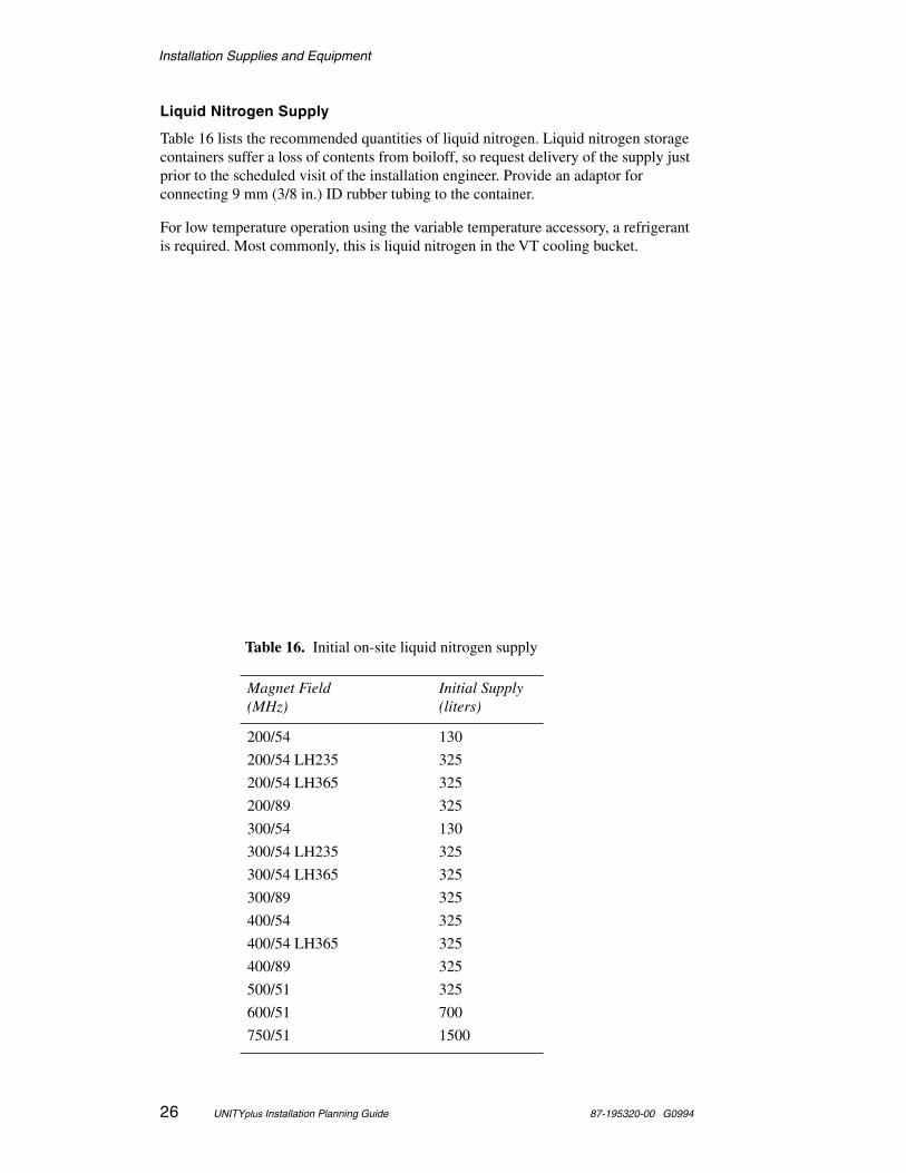
Liquid Nitrogen Supply
Table 16 lists the recommended quantities of liquid nitrogen. Liquid nitrogen storage containers suffer a loss of contents from boiloff, so request delivery of the supply just prior to the scheduled visit of the installation engineer. Provide an adaptor for connecting 9 mm (3/8 in.) ID rubber tubing to the container.
For low temperature operation using the variable temperature accessory, a refrigerant is required. Most commonly, this is liquid nitrogen in the VT cooling bucket.
Table 16. Initial on-site liquid nitrogen supply
Magnet Field(MHz)
Initial Supply(liters)
200/54 130
200/54 LH235 325
200/54 LH365 325
200/89 325
300/54 130
300/54 LH235 325
300/54 LH365 325
300/89 325
400/54 325
400/54 LH365 325
400/89 325
500/51 325
600/51 700
750/51 1500
Installation Supplies and Equipment
87-195320-00 G0994 UNITYplus Installation Planning Guide 27
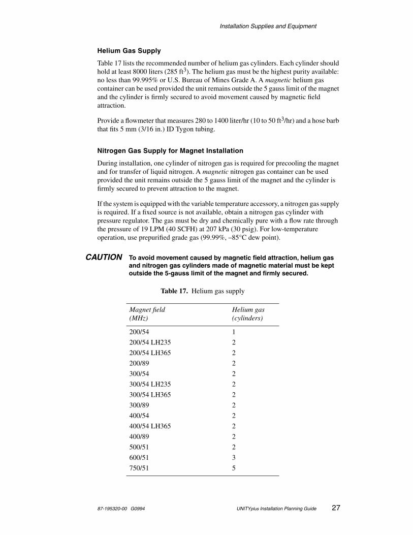
Helium Gas Supply
Table 17 lists the recommended number of helium gas cylinders. Each cylinder should hold at least 8000 liters (285 ft3). The helium gas must be the highest purity available: no less than 99.995% or U.S. Bureau of Mines Grade A. A magnetic helium gas container can be used provided the unit remains outside the 5 gauss limit of the magnet and the cylinder is firmly secured to avoid movement caused by magnetic field attraction.
Provide a flowmeter that measures 280 to 1400 liter/hr (10 to 50 ft3/hr) and a hose barb that fits 5 mm (3/16 in.) ID Tygon tubing.
Nitrogen Gas Supply for Magnet Installation
During installation, one cylinder of nitrogen gas is required for precooling the magnet and for transfer of liquid nitrogen. A magnetic nitrogen gas container can be used provided the unit remains outside the 5 gauss limit of the magnet and the cylinder is firmly secured to prevent attraction to the magnet.
If the system is equipped with the variable temperature accessory, a nitrogen gas supply is required. If a fixed source is not available, obtain a nitrogen gas cylinder with pressure regulator. The gas must be dry and chemically pure with a flow rate through the pressure of 19 LPM (40 SCFH) at 207 kPa (30 psig). For low-temperature operation, use prepurified grade gas (99.99%, –85°C dew point).
CAUTION To avoid movement caused by magnetic field attraction, helium gas and nitrogen gas cylinders made of magnetic material must be kept outside the 5-gauss limit of the magnet and firmly secured.
Table 17. Helium gas supply
Magnet field(MHz)
Helium gas(cylinders)
200/54 1
200/54 LH235 2
200/54 LH365 2
200/89 2
300/54 2
300/54 LH235 2
300/54 LH365 2
300/89 2
400/54 2
400/54 LH365 2
400/89 2
500/51 2
600/51 3
750/51 5
Installation Supplies and Equipment
28 UNITYplus Installation Planning Guide 87-195320-00 G0994
Face Mask and Thermal Gloves
If cryogenic helium or nitrogen contact living tissue, a serious injury (similar to a burn) can occur. Order appropriate safety coverings for use during dewar servicing, including a mask that protects the face completely and loose-fitting thermal gloves.
WARNING Avoid helium or liquid nitrogen contact with any part of the body. If liquid helium or nitrogen contact living tissue, a serious injury (similar to a burn) can occur. Never place your head over the helium and nitrogen exit tubes on top of the magnet. If helium or nitrogen contacts the body, seek medical attention, especially if the skin is blistered or the eyes are affected.
Heat Gun
Order a 120 Vac, 20 A heat gun (Dayton Model 27046 or equivalent) for thawing ice accumulation and drying out moisture on dewar servicing equipment.
Nonferromagnetic Ladder
Acquire a 90 to 120 cm (3 to 4 ft) nonferromagnetic ladder for reaching the top of the dewar while inserting and removing the helium transfer tube. The ladder should be sturdy and self-supporting with rubber feet. A somewhat taller 120 to 180 cm (4 to 6 ft) ladder is recommended for widebore and 400-, 500-, and 600-MHz magnets.
Hoist
A hoist must be available to remove the magnet from the crate, assemble it, and move it into place. The capacity of the hoist depends on the weight of the magnet being installed. Table 2 on page 3 specifies magnet weights. Allow a safety factor of at least 100% above the weight shown.
The hoist can be a chain hoist suspended from a moveable mechanism, such as an A-frame, or it can be permanently fixed above the area designated for the magnet, such as a beam. Consult your plant facilities department or authorized Varian representative to ensure that adequate facilities are available.
Isopropyl Alcohol and Acetone (Systems with an Oxford Magnet)
Obtain 1 pint (500 cm3) each of isopropyl alcohol and acetone. These solvents are needed to clean the magnet parts before assembly.
Cryogenic Equipment Rack (Recommended)
Various items are used around the magnet for routine maintenance and handling. These include helium transfer tube, flutter tube, Tygon tubing, stingers, and so on. To protect the cryogenic equipment from damage and to keep it conveniently available, provide a rack to hold the items. A 1.2 m × 2.4 m (4 ft × 8 ft) peg board hung on a laboratory wall, with wood or plastic pegs, works very well.

Installation Supplies and Equipment
87-195320-00 G0994 UNITYplus Installation Planning Guide 29
Electrical Power Surge Protector (Recommended)
To protect the delicate electrical components of the computer system (monitor, disk drive unit, CPU base, etc.), a good quality surge protector should be inserted in the power circuit serving the components. A single surge protector with six outlets will suffice if the components are located relatively close to one another. Contact an electronic professional for advice on quality surge protection in your area.
Monitor Degaussing Coil (Recommended)
The display monitor can gradually become somewhat magnetized due to its proximity to the magnet. This condition can be corrected with a degaussing coil. If the host computer system will be located near the edge of the 1–2 gauss stray field of the magnet, it will be necessary to have the degaussing coil.
Computer Preparation
30 UNITYplus Installation Planning Guide 87-195320-00 G0994
Computer Preparation
Varian UNITYplus spectrometers are operated using a Sun Microsystems computer, which may have been purchased from Varian or separately. In either case, certain preparations are required. Some of these preparations have been outlined previously in the section “Electrical Outlets.” The following sections contain additional considerations.
Magnetic Field Considerations for Computers and Peripherals
The spectrometer host computer system and storage media (in other words, streaming magnetic tape cartridge) must be located at a sufficient distance from the magnet that the magnetic field cannot damage the data. For a Sun workstation, this specification is less than 5 gauss. The distances at which this gauss level is present are different for each kind of magnet and must be taken into account when planning the room size. See the field plots in Appendix B on page 41 for typical distances at which various gauss levels exist for particular magnets, but be aware that these distances will vary somewhat for each magnet and should be checked after a magnet is installed.
Sun Computers
Varian currently supports the Sun computer models shown in Table 18. This table also lists the versions of SunOS and Solaris that are compatible with VNMR.
Other models that have been sold in the recent past are fully documented in the installation manuals, including the SPARCstation 1 and SPARCstation 1+. If you
Table 18. Sun systems, architecture, SunOS, and Solaris versions
Sun System Sun Architecture SunOS Version Solaris Version
SPARCstation 20SPARCstation 5
Sun-4m 4.1.3_U1, 4.1.4*
*. SunOS 4.1.4 (referred to as Solaris 1.1.2) requires a DMA-compatible HAL.
2.3, 2.4
SPARCclassicSPARCstation LX
Sun-4m 4.1.3C†, 4.1.3_U1, 4.1.4
†. SunOS 4.1.3C (referred to by Sun as Solaris1.1C) only works with the SPARCclassic and LX.
2.3, 2.4
SPARCstation 10 Sun-4m 4.1.3, 4.1.3_U1, 4.1.4
2.3, 2.4
SPARCstation IPXSPARCstation IPCSPARCstation ELCSPARCstation SLCSPARCstation 2SPARCstation 1+SPARCstation 1
Sun-4c 4.1.2, 4.1.3, 4.1.3_U1, 4.1.4
2.3, 2.4
SPARCstation 330 Sun-4 4.1.1, 4.1.2, 4.1.3‡
‡. Using 4.1.3 on a Sun-4 requires building a new kernel and modifying the setacq program.
Not Supported
Computer Preparation
87-195320-00 G0994 UNITYplus Installation Planning Guide 31
purchase a computer from a source other than Varian, or plan to use an existing computer, any of the computers listed here are acceptable.
Computers must have 8 megabytes (MB) of RAM or more. One or more (up to three) hard disks (internal and/or external) can be present, with a minimum total disk space of 207 MB. Monitors can be any size, monochrome or color. Graphics can be “plain” or the GX version (the GX version provides higher performance). Graphics higher than GX (that is, GXplus, GS, GT) are not used by Varian software. Varian has not performed a full evaluation of higher lever graphics boards and cannot guarantee complete compatibility.
Sun Peripherals
Sun operating system software (SunOS), as discussed below, is shipped on a CD-ROM and can be installed either locally (on a computer to which the CD-ROM unit is attached) or remotely. You must have a CD-ROM drive available for installation of SunOS—a CD-ROM drive is not automatically included with the computer or with a spectrometer purchase. Varian VNMR software is provided on 1/4-inch and 8-mm tape, and instructions are only provided for installing it locally or remotely. To install VNMR software, you must have available, either directly connected to the computer or to a computer to which that computer is networked, a 1/4-inch or 8-mm tape drive.
SunOS Media
Sun computers, whether purchased from Sun or from Varian, include the UNIX “right-to-use” license. In general, they do not have the operating system media included (some Sun computers purchased through Varian do include a CD-ROM); that is, a CD-ROM containing the relevant version of SunOS. Media is separately purchased. One copy of the media on hand for the installation is required, and this media must be for the relevant version of SunOS (currently 4.1.3 for all computers except SPARCclassic and SPARCstation LX, 4.1.3C for SPARCclassic and SPARCstation LX). You may purchase the CD-ROM from Varian (Part No. 00-993277-00 for 4.1.3 or Part No. 00-901451-00 for 4.1.3C), you may purchase it from Sun through “SunExpress” (phone 1-800-USA4SUN, Sun P/N SX-21 (CD-ROM)), or you may borrow it from another computer (this is completely legal because of your right-to-use license).
SunOS Installation
The Software Installation Manual contains complete instructions for configuring the Sun computer and installing the Sun operating system software according to Varian specifications. Sun computers operating either as a host or as a separate data station require specific setup and configuration for SunOS installation that are not met by the “preloaded” configuration supplied by Sun with the computer.
If you have purchased your computer from Varian, Varian assumes full responsibility and will install both the Sun operating system software and the VnmrS and/or VnmrX software, subject to the constraints discussed above under “SunOS Media” and “Sun Peripherals.”
If you have purchased your Sun from another source, you are responsible for configuring the hardware and installing the SunOS software according to the instructions contained in the Software Installation Manual (you can request a free copy
Computer Preparation
32 UNITYplus Installation Planning Guide 87-195320-00 G0994
through Varian Technical Support or through your local Varian sales and service organization). Installation will not start until the computer system is properly configured; however, you are not expected to install the Varian VnmrS and/or VnmrX software.
There is an exception: If you have purchased a Sun computer from a source other than Varian and if you have a knowledge of UNIX system administration and if that computer came with SunOS preloaded, it is possible to reconfigure the preloaded SunOS so that it can be used for VNMR operation. In this case only, a copy of the SunOS media is not required. Guidelines (but not step-by-step instructions) are contained in the Software Installation Manual for the case of a two-disk system. A single 207-MB hard drive system does have sufficient room to install VNMR on top of the preloaded SunOS, although only a small amount of space to store NMR data will remain. Varian installers are not trained to perform these operations. If you have purchased the Sun computer from Varian, you must have a copy of the SunOS CD-ROM available for the installer to use.
Sun Documentation
The Varian manual Software Installation Manual contains full, step-by-step instructions for installing SunOS and Solaris, and the System Operation Manual contains information to operate your spectrometer and interact with UNIX. The Sun computer also comes with the “Desktop SPARC manual set,” which provides user-level documentation on the basic features of UNIX. Additionally, SunOS contains extensive on-line documentation (accessed by the man command). For these reasons, full Sun UNIX documentation is not included with the purchase of a Sun computer (whether from Varian or another source).
Full documentation is available from Sun through SunExpress (SX-09), but such documentation is definitely not required for installation or use of the system.
Computer Preparation Checklist
❏ Sun computer is SPARCstation ELC, IPC, IPX, or SPARCstation 1, 1+, 2, 10, Classic, or LX.
❏ Hard disk drive is 207 MB or larger.
❏ 150-MB, 1/4-inch tape unit or 8-mm tape unit is installed or available on a networked computer.
❏ CD-ROM drive is installed or available on a networked computer.
❏ Sun operating system media is available (CD-ROM).
If you have purchased the Sun computer from a source other than Varian:
❏ Copy of current Software Installation Manual in-house.
❏ Computer installed and configured according to Varian specifications.
❏ Sun operating system installed and configured according to Varian specifications.
Computer Preparation
87-195320-00 G0994 UNITYplus Installation Planning Guide 33
Configuration and Peripherals
“Appendix E. Peripheral Compatibility” on page 63 lists peripherals that can be used with Varian UNITYplus NMR spectrometers. These devices fall into a number of compatibility categories, ranging from “fully tested” to “unknown,” which are described in Appendix E. Most of the products in the “fully tested” category are available from Varian.
This information is provided solely as a courtesy to those users who wish to purchase their own peripherals (or who may already have these items). Products in other categories are not sold by Varian, and Varian assumes no responsibility for their purchase or use, but provides this information solely for your discretionary use.
Collecting System and Network Information
The Solaris installation program asks you to supply some system and network information before installation begins. You can save time by collecting this information now, before booting from the Solaris 2.3 CD-ROM.
Use the “Pre-Installation Worksheet” on page 35 to record your system information. Each field on the worksheet is described below.
If your system is not connected to a network, you need to know or create only the hostname, root password, and the time zone. If your system is on a network, you need additional information that is described in this section. If unsure, contact your network administrator.
System Configuration Type
You are asked to configure your computer as one of the following: server, standalone, or dataless client. A server is a system that provides network services such as file transfer and storage space. A standalone system is a system that contains its own hard disk and bootup files. A dataless client, sometimes called diskless client, is a system without its own hard disk and uses an NFS server for the operating system, storage, and other services. For the purposes of VNMR, you will install your system as a standalone system.
Selecting a Hostname
A computer on a network is often called a host. Its hostname is the name that uniquely identifies the computer. If you already have a version of UNIX installed, you can use the command uname -n from within a C Shell to display this information for a Sun computer.
When choosing a hostname, make sure the name you select is unique within both your local area network and, if applicable, your name service domain.
In many networks, the choice of a hostname is left up to the owner of the computer (subject to the requirement of uniqueness). A hostname can be up to 64 upper case or lower case characters. It is strongly recommended that you use all lower case characters in the hostname because some networking software that might be used in other computers on the network could require lower case hostnames. Choose a name that starts with a lower case letter, followed by any combination of lower case letters, numbers, or hyphens. The name, however, cannot end with a hyphen.

Computer Preparation
34 UNITYplus Installation Planning Guide 87-195320-00 G0994
Obtaining the IP Address
Your computer must have a unique Internet Protocol ((IP) network address if your computer is to be attached to a network. Consult your network administrator about the address. If the software is being installed on a computer that is already connected to a network, the command ypcat hosts | grep `uname -n` can be used to display the IP address of your computer. Note the use of back quotes ( ` ) in this command.
Selecting a Subnet Mask
The subnet mask is a number that is used to split IP addresses into the network (Internet) and host parts. If your site does not use multiple subnets, use the default number, otherwise consult your network administrator. For a computer connected to a network, the command cat /etc/netmasks can be used.
Selecting the Name Service Type
The name service prompt allows choosing between NIS, NIS+, and none. If you choose NIS or NIS+, you need to enter the hostname and the IP address of the computer from which you receive the service. If you choose none, you are not prompted for additional information. Ask your network administrator what name service the network uses.
Entering the Hostname and IP Address of the Name Server
If you select either NIS or NIS+ as the name service type, it is assumed that there is a different computer on the network that is the current NIS or NIS+ server. You are asked to enter the hostname and IP address of the server that provides the name service. On an existing computer, the server’s name can be displayed by entering the command ypwhich. The server's IP address, and other information, can be displayed by entering the command ypcat hosts | grep `ypwhich`. Again, note the use of back quotes ( ` ).
Domain Name
The domain name is the name assigned to a group of computers that are administered together. All computers in the group (domain) are accessed by the same NIS or NIS+ maps. Your network administrator should be able to provide the domain name. Or the domain name can be found by entering the command domainname.
Setting the Time Zone
Solaris software uses world time zones and automatically adjusts the system clock for daylight-savings time if appropriate. Time zones are specified by name, such as “US/Central.”
Disk Layout
Your computer must contain at least one hard disk drive. If only one disk drive is installed, use the default layout provided by the software. If more than one drive is installed, accept the default layout or select the drive to receive the software during the installation process. See the Software Installation Manual.

Computer Preparation
87-195320-00 G0994 UNITYplus Installation Planning Guide 35
Pre-Installation Worksheet
Write down your system and network information here in preparation for the questions that are asked during the installation process.
Category Your Configuration
System Configuration Type Choices: Server, Standalone, or Dataless Client
Standalone
Hostname Example: mysystem
IP Address Example: 195.5.2.15
Subnet Mask Example: 255.255.255.0
Name Service Choices: NIS, NIS+, or none
Name Server Hostname Example: ourserver
Name Server IP Address Example: 195.5.2.25
Domain Name Example: our.domain
Time Zone Examples: US/Mountain, US/Pacific, US/Eastern
Disk Layout Examples: / = c0t0d0s0, swap = c0t0d0s1, /usr = c0t0d0s6 Use the default proposed by the installation program

Receiving Preparations
36 UNITYplus Installation Planning Guide 87-195320-00 G0994
Receiving Preparations
The method of shipping and the current conditions at the destination determine the extent of the receiving preparations. The Varian Order Acknowledgment form indicates the shipping method for the order. The following service is usually provided:
• Air Freight. System is delivered to unloading dock or other easily accessible outside unloading point. Factory to destination transit time is about two days (not including time to clear customs).
• Motor or Moving Van. System is delivered to an easily accessible interior location or any interior location to which freight can be easily transported by movable dolly. Excluded is transport in elevators that cannot support the weight of the shipment or up stairways. Factory to destination within the United States is about eight days.
Confirm that the local shipping company uses a vehicle that will allow the magnet to be transported in an upright position for all transport methods that will be used. See Tables 1 through 3 for dimensions and weights of major system components.
Contact the shipping company locally about the service usually rendered. If moving equipment will be required at the site, obtain help from the plant facilities department or an outside moving service.
Sea freight or motor freight without air cushion suspension is not recommended for long distance delivery of systems.

Postdelivery Instructions
87-195320-00 G0994 UNITYplus Installation Planning Guide 37
Postdelivery Instructions
When the system is delivered, follow the instructions below to inspect for shipping damage before moving the crates. Do not open any crate.
Inspecting for Shipping Damage
CAUTION Do not open any crate except with direct instructions from an authorized Varian service representative. In particular, the crate containing the magnet has components that could be irreparably damaged if opened incorrectly.
When the shipment arrives, make an immediate visual inspection of the outside of each crate for damage. Take the following steps if any damage is found:
1. Note the nature of the damage on the carrier's waybill.
2. Request an inspection and written damage report by a representative of the carrier.
3. Forward a copy of the damage report to the local Varian representative.
In case of damage, the FOB block on the Varian Order Acknowledgment form determines owner responsibility:
• FOB PALO ALTO. Transfer of ownership occurs when the shipment leaves the factory. The customer is responsible for claims for shipping damage. Upon request, Varian will provide assistance in filing claims.
• FOB DESTINATION. Transfer of ownership occurs at customer's point of receipt. Varian is responsible for claims for shipping damage.
Damage discovered fifteen or more days after delivery generally cannot be recovered. Such damage will be at the expense of the customer.
Moving the System
CAUTION Move the crates in an upright position. Do not drop or mishandle. The crates are packed with G-force and “tip-and-tell” indicators that record mishandling. Be especially careful about moving the magnet crate. If one or more crates cannot be moved into the installation site because of doorway clearance, leave the affected crates in a clean, safe, dry location. Do not open any crate except with direct instructions from an authorized service representative.
If possible, move the crates in an upright position, with a forklift or hydraulic pallet mover, directly to the installation site. Should it appear necessary to uncrate one or more units because of doorway or passage clearance, contact your Varian service representative for further instructions.
To avoid unnecessary expense, be sure moving personnel and equipment are ready for the shipment on the delivery day.

Postdelivery Instructions
38 UNITYplus Installation Planning Guide 87-195320-00 G0994

Appendix A. Installation Checklists
87-195320-00 G0994 UNITYplus Installation Planning Guide 39
Appendix A. Installation Checklists
Predelivery
Use the following checklist to prepare for delivery of the system. Refer to this manual for further instructions and safety precautions. Consult knowledgeable individuals, such as plant facilities personnel, for assistance in implementing these instructions.
❏ 1. Check the “SHIP BY” date on the Varian Order Acknowledgment form. Use this date as a target for completing installation preparations.
❏ 2. Select the site for installing and operating the system. (Note: a site survey is standard with many UNITYplus spectrometer systems.)
❏ 3. Prepare the installation site, including electrical outlets, compressed air supply, and air conditioning. Make any computer preparations required.
❏ 4. Order supplies and equipment for installation and startup operation.
❏ 5. Make arrangements for workers and equipment to move the system upon delivery to the installation site.
❏ 6. Read carefully, sign, and mail to Varian the “Object Code License Form.” (Note that acceptance of the products on the Order Acknowledgment form will constitute acceptance of the terms stated in the Object Code License Form, whether the form is signed or not.)
Postdelivery
Use the checklist below to plan for handling the instrument after delivery. Refer to “Postdelivery Instructions” on page 37 for further instructions and safety precautions.
❏ 1. Upon delivery, check for shipping damage but do not open any shipping crates except with direct instructions from an authorized service representative. Examine crates for shipping damage. Note any apparent damage on the carrier's waybill and contact the insurance company.
❏ 2. As soon as possible, move the shipment to a clean, dry location (preferably the installation site). Move the crates in an upright position. Do not drop or mishandle. The crates are packed with G-force and “tip-and-tell” indicators that record mishandling. If one or more crates cannot be moved into the installation site because of doorway clearance, leave the affected crate in a clean, safe, dry location. Again, do not open any crate except with direct instructions from an authorized service representative. In particular, the crate containing the magnet has components that could be irreparably damaged if opened incorrectly.
❏ 3. Contact Varian to schedule the visit of an installation engineer after the shipment is moved to the installation site, the utilities are installed, and non-Varian installation parts and supplies (listed in the “Installation Supplies and Equipment” section) are received. For installations in the United States, telephone the Installation Department at (415) 424-6361. For installations in other locations, contact the nearest Varian sales or service office, listed in Appendix E of this guide.

Appendix A. Installation Checklists
40 UNITYplus Installation Planning Guide 87-195320-00 G0994
Appendix B. Stray Field Plots
87-195320-00 G0994 UNITYplus Installation Planning Guide 41
Appendix B. Stray Field Plots
This appendix shows stray field plots for each magnet (listed as MHz/mm). The axial and radial distances shown are measured in meters from the magnet centerline (CL). The values are typical but may vary between individual magnets. Gauss levels should be checked after a particular magnet has been installed. The values in Table 19 were copied from Oxford technical manuals.
Table 19. Stray field data for NMR magnet systems
Magnet Systems
Axial Distance (m) from Magnet Center Line
Radial Distance (m) from Magnet Center Line
MHz/mm 5-gauss 10-gauss 25-gauss 5-gauss 10-gauss 25-gauss
200/54 1.82 1.45 1.05 1.47 1.20 0.90
200/89 2.65 2.05 1.49 2.00 1.60 1.15
300/54 2.20 1.75 1.26 1.70 1.30 0.97
300/89 2.75 2.20 1.63 2.20 1.75 1.26
400/54 2.80 2.24 1.65 2.20 1.76 1.29
400/89 3.80 3.00 2.21 3.05 2.40 1.74
500/51 3.45 2.70 2.00 2.75 2.20 1.60
600/51 4.55 3.60 2.67 3.60 2.85 2.10
750/51 7.60 6.04 4.45 6.04 4.79 3.53
Appendix B. Stray Field Plots
42 UNITYplus Installation Planning Guide 87-195320-00 G0994
Figure 7. Stray field plots for 200/54 and 200/89 magnets
field values in gauss
1.0 2.0
2.0
1.0
200/54 magnet
0.5
1.5
0.5 1.5
Axi
al d
ista
nce
from
mag
net C
L (m
)
Radial distance from magnet CL (m)
1.82
1.47
51.45
1.20
10
0.90
1.05
25
field values in gauss
1.0 2.0
2.0
1.0
200/89 magnet
0.5
1.5
0.5 1.5
Axi
al d
ista
nce
from
mag
net C
L (m
)
Radial distance from magnet CL (m)
2.65
2.00
2.05
1.601.15
1.49
5
10
25
Appendix B. Stray Field Plots
87-195320-00 G0994 UNITYplus Installation Planning Guide 43
Figure 8. Stray field plots for 300/54 and 300/89 magnets
field values in gauss
1.0 2.0
2.0
1.0
300/54 magnet
0.5
1.5
0.5 1.5
Axi
al d
ista
nce
from
mag
net C
L (m
)
Radial distance from magnet CL (m)
2.20
1.70
1.75
1.300.97
1.26
field values in gauss
1.0 2.0
2.0
1.0
300/89 magnet
0.5
1.5
0.5 1.5
Axi
al d
ista
nce
from
mag
net C
L (m
)
Radial distance from magnet CL (m)
2.75
2.20
2.20
1.751.26
1.63
5
10
25
2.55
10
25

Appendix B. Stray Field Plots
44 UNITYplus Installation Planning Guide 87-195320-00 G0994
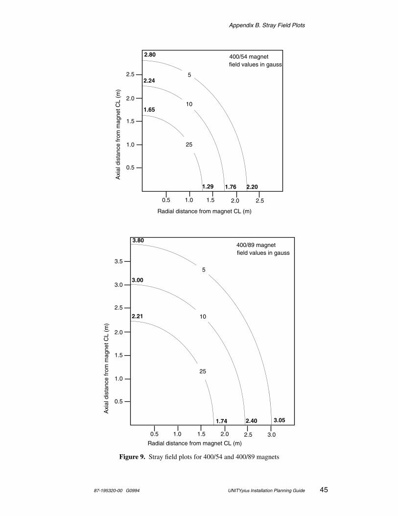
Appendix B. Stray Field Plots
87-195320-00 G0994 UNITYplus Installation Planning Guide 45
Figure 9. Stray field plots for 400/54 and 400/89 magnets
field values in gauss
1.0 2.0
2.0
1.0
400/54 magnet
0.5
1.5
0.5 1.5
Axi
al d
ista
nce
from
mag
net C
L (m
)
Radial distance from magnet CL (m)
2.80
2.20
2.24
1.761.29
1.65
field values in gauss
1.0 2.5
2.0
1.0
400/89 magnet
0.5
1.5
0.5 1.5
Axi
al d
ista
nce
from
mag
net C
L (m
)
Radial distance from magnet CL (m)
3.80
3.05
3.00
2.401.74
2.212.5
2.5
2.5
2.0
5
10
25
3.0
3.0
3.55
10
25
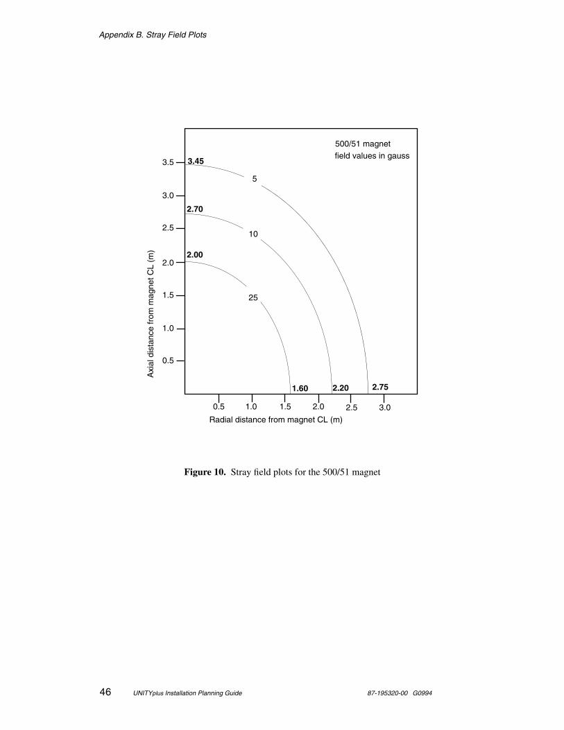
Appendix B. Stray Field Plots
46 UNITYplus Installation Planning Guide 87-195320-00 G0994
Figure 10. Stray field plots for the 500/51 magnet
field values in gauss
1.0 2.5
2.0
1.0
500/51 magnet
0.5
1.5
0.5 1.5
Axi
al d
ista
nce
from
mag
net C
L (m
)
Radial distance from magnet CL (m)
3.45
2.75
2.70
2.201.60
2.00
2.5
2.0 3.0
3.0
3.5
5
10
25
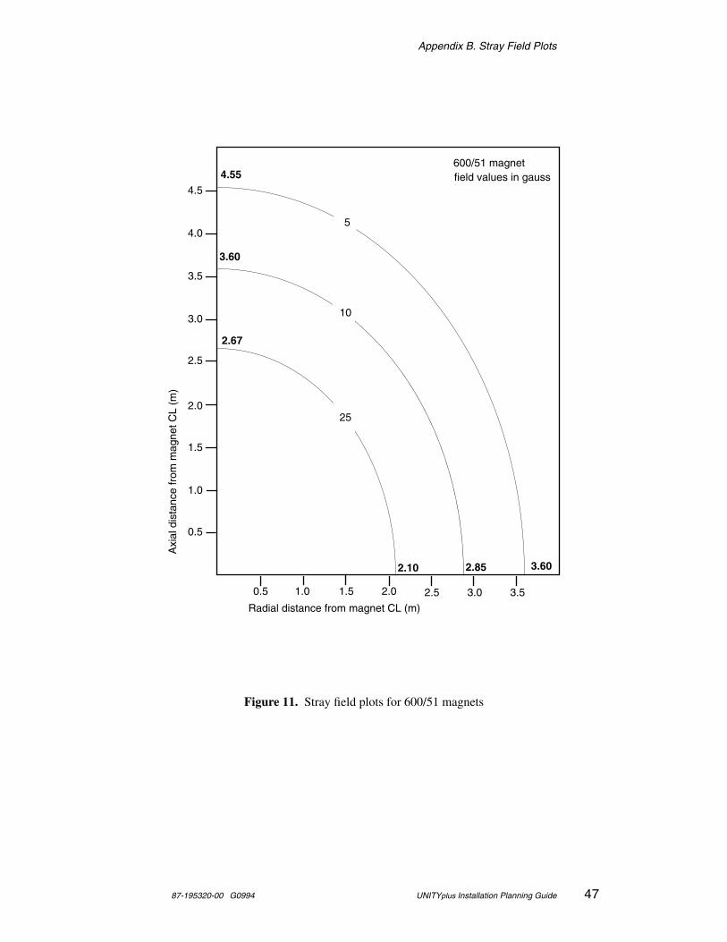
Appendix B. Stray Field Plots
87-195320-00 G0994 UNITYplus Installation Planning Guide 47
Figure 11. Stray field plots for 600/51 magnets
field values in gauss
1.0 2.5
2.0
1.0
600/51 magnet
0.5
1.5
0.5 1.5
Axi
al d
ista
nce
from
mag
net C
L (m
)
Radial distance from magnet CL (m)
4.55
3.60
3.60
2.852.10
2.67
2.5
2.0 3.0
3.0
3.5
4.0
4.5
3.5
5
10
25

Appendix B. Stray Field Plots
48 UNITYplus Installation Planning Guide 87-195320-00 G0994
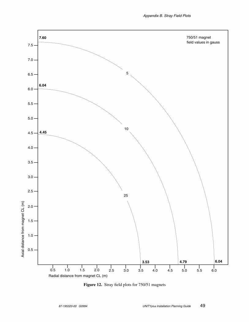
Appendix B. Stray Field Plots
87-195320-00 G0994 UNITYplus Installation Planning Guide 49
Figure 12. Stray field plots for 750/51 magnets
field values in gauss
1.0 2.5
2.0
1.0
750/51 magnet
0.5
1.5
0.5 1.5
Axi
al d
ista
nce
from
mag
net C
L (m
)
Radial distance from magnet CL (m)
7.60
6.04
6.04
4.793.53
4.45
2.5
2.0 3.0
3.0
3.5
4.0
4.5
3.5
5.0
5.5
6.0
6.5
7.0
7.5
4.0 4.5 5.0 5.5 6.0
5
10
25
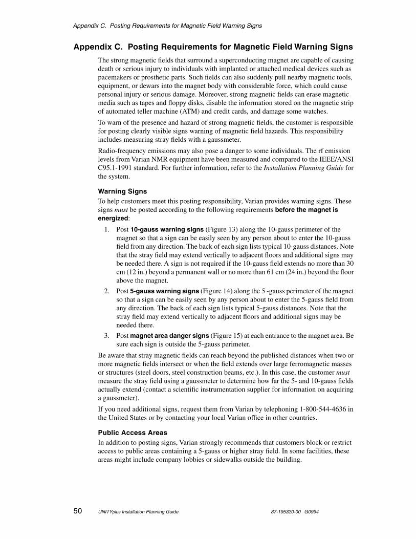
Appendix C. Posting Requirements for Magnetic Field Warning Signs
50 UNITYplus Installation Planning Guide 87-195320-00 G0994
Appendix C. Posting Requirements for Magnetic Field Warning Signs
The strong magnetic fields that surround a superconducting magnet are capable of causing death or serious injury to individuals with implanted or attached medical devices such as pacemakers or prosthetic parts. Such fields can also suddenly pull nearby magnetic tools, equipment, or dewars into the magnet body with considerable force, which could cause personal injury or serious damage. Moreover, strong magnetic fields can erase magnetic media such as tapes and floppy disks, disable the information stored on the magnetic strip of automated teller machine (ATM) and credit cards, and damage some watches.
To warn of the presence and hazard of strong magnetic fields, the customer is responsible for posting clearly visible signs warning of magnetic field hazards. This responsibility includes measuring stray fields with a gaussmeter.
Radio-frequency emissions may also pose a danger to some individuals. The rf emission levels from Varian NMR equipment have been measured and compared to the IEEE/ANSI C95.1-1991 standard. For further information, refer to the Installation Planning Guide for the system.
Warning SignsTo help customers meet this posting responsibility, Varian provides warning signs. These signs must be posted according to the following requirements before the magnet is energized:
1. Post 10-gauss warning signs (Figure 13) along the 10-gauss perimeter of the magnet so that a sign can be easily seen by any person about to enter the 10-gauss field from any direction. The back of each sign lists typical 10-gauss distances. Note that the stray field may extend vertically to adjacent floors and additional signs may be needed there. A sign is not required if the 10-gauss field extends no more than 30 cm (12 in.) beyond a permanent wall or no more than 61 cm (24 in.) beyond the floor above the magnet.
2. Post 5-gauss warning signs (Figure 14) along the 5 -gauss perimeter of the magnet so that a sign can be easily seen by any person about to enter the 5-gauss field from any direction. The back of each sign lists typical 5-gauss distances. Note that the stray field may extend vertically to adjacent floors and additional signs may be needed there.
3. Post magnet area danger signs (Figure 15) at each entrance to the magnet area. Be sure each sign is outside the 5-gauss perimeter.
Be aware that stray magnetic fields can reach beyond the published distances when two or more magnetic fields intersect or when the field extends over large ferromagnetic masses or structures (steel doors, steel construction beams, etc.). In this case, the customer must measure the stray field using a gaussmeter to determine how far the 5- and 10-gauss fields actually extend (contact a scientific instrumentation supplier for information on acquiring a gaussmeter).
If you need additional signs, request them from Varian by telephoning 1-800-544-4636 in the United States or by contacting your local Varian office in other countries.
Public Access AreasIn addition to posting signs, Varian strongly recommends that customers block or restrict access to public areas containing a 5-gauss or higher stray field. In some facilities, these areas might include company lobbies or sidewalks outside the building.

Appendix C. Posting Requirements for Magnetic Field Warning Signs
87-195320-00 G0994 UNITYplus Installation Planning Guide 51
Safety TrainingCustomers must provide on-site training about magnetic field hazards to any person who may be exposed to 5-gauss or stronger stray fields.
Figure 13. 10-gauss warning sign (Pub. No. 87-250302-00)
Tools and EquipmentStrong magnetic fields are present that can make magnetic items suddenly fly towards the magnet, which could cause personal injury or serious damage. Do not take tools, equipment, or personal items containing steel, iron, or other magnetic materials closer to the magnet than this sign.
DewarsThe stray field of the magnet can pull a magnetic dewar into the magnet body, causing serious damage. Use only nonmagnetic stainless steel dewars. Do not use iron or steel dewars during servicing.
STRONG MAGNETIC FIELD
Pub. No. 87-250302-00 B0694 10-Gauss Warning Sign
10-GAUSSWARNING
Figure 14. 5-gauss warning sign (Pub. No. 87-250303-00)
Pacemaker, Metallic Implant HazardStrong magnetic and rf fields are present that can cause serious injury or death to persons with implanted or attached medical devices, such as pacemakers and prosthetic parts. Such persons must not go closer to the magnet than this sign until safety at a closer distance is identified by a physician or device manufacturer.
Magnetic Media, ATM/Credit CardsStrong magnetic fields are present that can erase magnetic media, disable ATM and credit cards, and damage some watches. Do not take such objects closer to the magnet than this sign.
STRONG MAGNETIC FIELD
Pub. No. 87-250303-00 B0694 5-Gauss Warning Sign
5-GAUSSWARNING
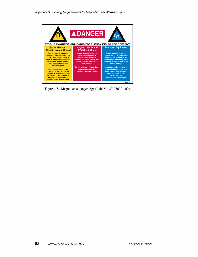
Appendix C. Posting Requirements for Magnetic Field Warning Signs
52 UNITYplus Installation Planning Guide 87-195320-00 G0994
Figure 15. Magnet area danger sign (Pub. No. 87-250301-00)
STRONG MAGNETIC AND RADIO-FREQUENCY FIELDS ARE PRESENT
Pub. No. 87-250301-00 B0694 Magnet Area Entrance Danger Sign
DANGER
Pacemaker and Metallic Implant Hazard
Strong magnetic and radio-frequency fields are present that
could cause serious injury or death to persons with implanted
or attached medical devices, such as pacemakers and
prosthetic parts.
Such persons must not go closer to the magnet than the 5-GAUSS WARNING signs until
safety at a closer distance is identified by a physician or
medical device manufacturer.
Tools and Equipment
Strong magnetic fields are present that could make some magnetic items suddenly fly
towards the magnet body, which could cause personal injury or
serious damage.
Do not take tools, equipment, or personal items containing steel, iron, or other magnetic
materials closer to the magnet than the
10-GAUSS WARNING signs.
Magnetic Media andATM/Credit Cards
Strong magnetic fields are present that could erase magnetic media such as
floppies and tapes, disable ATM and credit cards, and damage
some watches.
Do not take such objects closer to the magnet than the
5-GAUSS WARNING signs.

Appendix C. Posting Requirements for Magnetic Field Warning Signs
87-195320-00 G0994 UNITYplus Installation Planning Guide 53
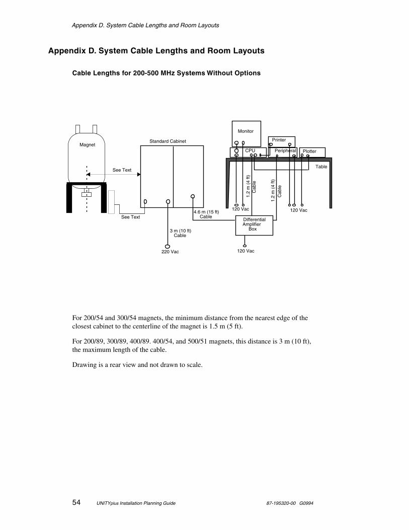
Appendix D. System Cable Lengths and Room Layouts
54 UNITYplus Installation Planning Guide 87-195320-00 G0994
Appendix D. System Cable Lengths and Room Layouts
Cable Lengths for 200-500 MHz Systems Without Options
For 200/54 and 300/54 magnets, the minimum distance from the nearest edge of the closest cabinet to the centerline of the magnet is 1.5 m (5 ft).
For 200/89, 300/89, 400/89. 400/54, and 500/51 magnets, this distance is 3 m (10 ft), the maximum length of the cable.
Drawing is a rear view and not drawn to scale.
220 Vac
Printer
Monitor
Table
120 Vac
120 Vac
DifferentialAmplifier
Box
Plotter
See Text
CPU Peripheral
Standard Cabinet
4.6 m (15 ft) Cable
3 m (10 ft)Cable
1.2
m (
4 ft)
C
able
See Text
1.2
m (
4 ft)
C
able
120 Vac
Magnet
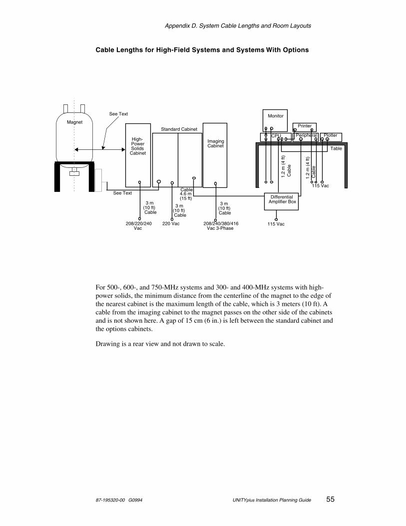
Appendix D. System Cable Lengths and Room Layouts
87-195320-00 G0994 UNITYplus Installation Planning Guide 55
Cable Lengths for High-Field Systems and Systems With Options
For 500-, 600-, and 750-MHz systems and 300- and 400-MHz systems with high-power solids, the minimum distance from the centerline of the magnet to the edge of the nearest cabinet is the maximum length of the cable, which is 3 meters (10 ft). A cable from the imaging cabinet to the magnet passes on the other side of the cabinets and is not shown here. A gap of 15 cm (6 in.) is left between the standard cabinet and the options cabinets.
Drawing is a rear view and not drawn to scale.
High- Power Solids
Cabinet
208/220/240Vac
220 Vac
Standard Cabinet
4.6 m (15 ft)
Cable
3 m (10 ft) Cable
Differential Amplifier Box
Printer
Monitor
Table
115 Vac
115 Vac
PlotterCPUImaging Cabinet
208/240/380/416 Vac 3-Phase
Peripheral
3 m (10 ft) Cable
3 m (10 ft) Cable
See Text
1.2
m (
4 ft)
C
able
See Text
1.2
m (
4 ft)
C
able
Magnet
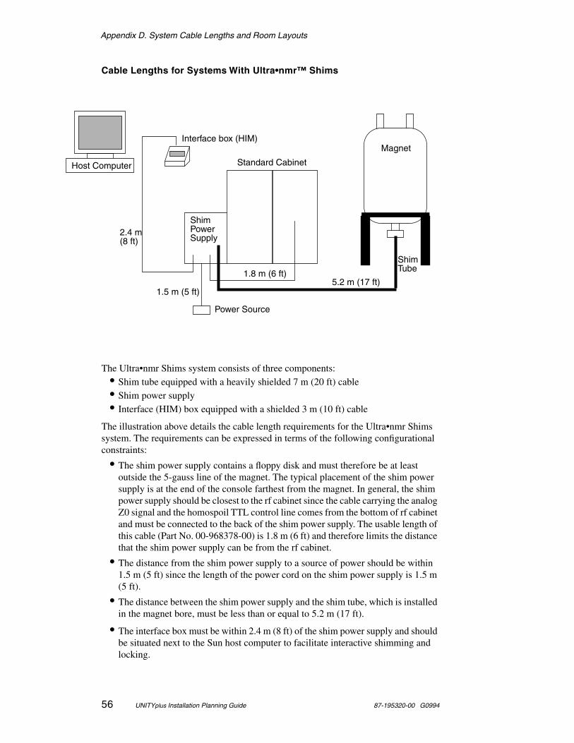
Appendix D. System Cable Lengths and Room Layouts
56 UNITYplus Installation Planning Guide 87-195320-00 G0994
Cable Lengths for Systems With Ultra•nmr™ Shims
The Ultra•nmr Shims system consists of three components: • Shim tube equipped with a heavily shielded 7 m (20 ft) cable• Shim power supply• Interface (HIM) box equipped with a shielded 3 m (10 ft) cable
The illustration above details the cable length requirements for the Ultra•nmr Shims system. The requirements can be expressed in terms of the following configurational constraints:
• The shim power supply contains a floppy disk and must therefore be at least outside the 5-gauss line of the magnet. The typical placement of the shim power supply is at the end of the console farthest from the magnet. In general, the shim power supply should be closest to the rf cabinet since the cable carrying the analog Z0 signal and the homospoil TTL control line comes from the bottom of rf cabinet and must be connected to the back of the shim power supply. The usable length of this cable (Part No. 00-968378-00) is 1.8 m (6 ft) and therefore limits the distance that the shim power supply can be from the rf cabinet.
• The distance from the shim power supply to a source of power should be within 1.5 m (5 ft) since the length of the power cord on the shim power supply is 1.5 m (5 ft).
• The distance between the shim power supply and the shim tube, which is installed in the magnet bore, must be less than or equal to 5.2 m (17 ft).
• The interface box must be within 2.4 m (8 ft) of the shim power supply and should be situated next to the Sun host computer to facilitate interactive shimming and locking.
Host Computer
Interface box (HIM)
Shim
Shim
5.2 m (17 ft)
2.4 m
1.8 m (6 ft)
Power Source
1.5 m (5 ft)
Magnet
Standard Cabinet
Tube
PowerSupply(8 ft)
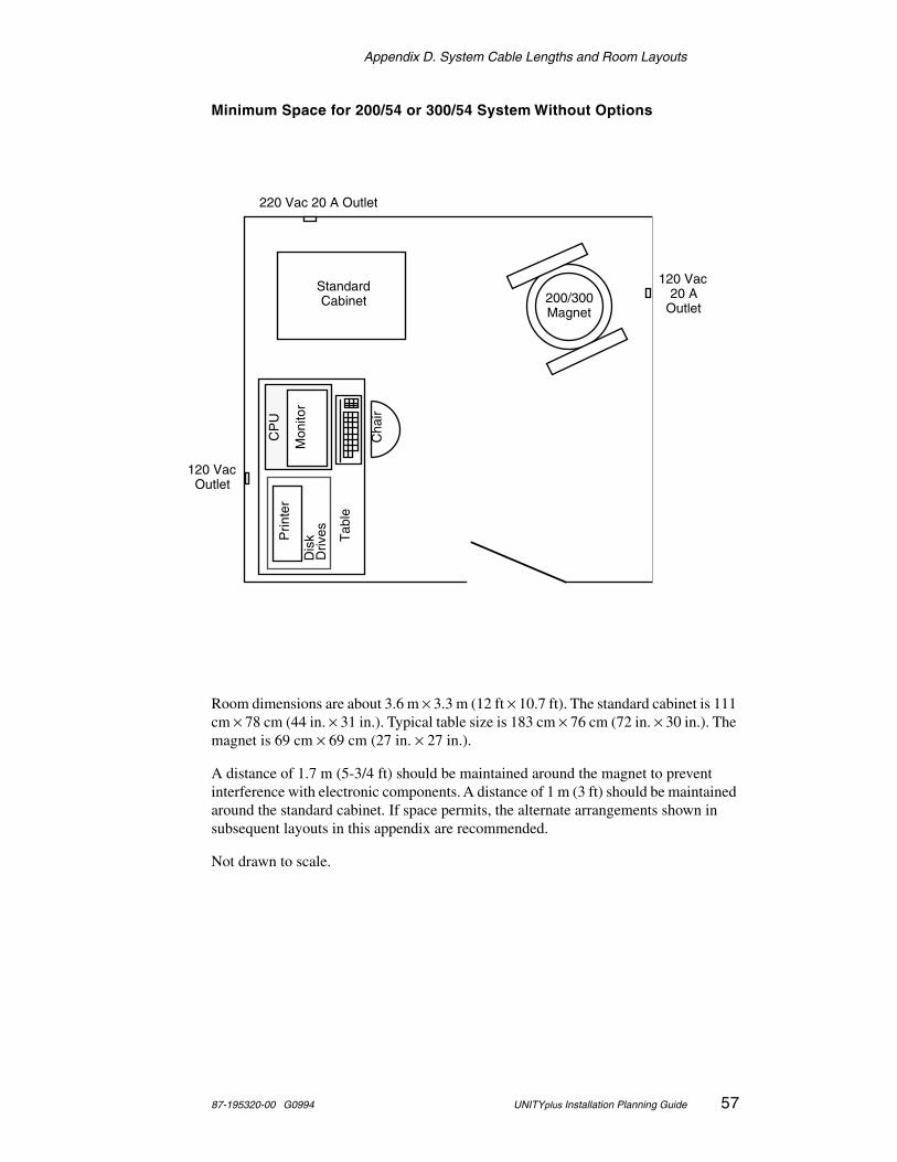
Appendix D. System Cable Lengths and Room Layouts
87-195320-00 G0994 UNITYplus Installation Planning Guide 57
Minimum Space for 200/54 or 300/54 System Without Options
Room dimensions are about 3.6 m × 3.3 m (12 ft × 10.7 ft). The standard cabinet is 111 cm × 78 cm (44 in. × 31 in.). Typical table size is 183 cm × 76 cm (72 in. × 30 in.). The magnet is 69 cm × 69 cm (27 in. × 27 in.).
A distance of 1.7 m (5-3/4 ft) should be maintained around the magnet to prevent interference with electronic components. A distance of 1 m (3 ft) should be maintained around the standard cabinet. If space permits, the alternate arrangements shown in subsequent layouts in this appendix are recommended.
Not drawn to scale.
220 Vac 20 A Outlet
120 Vac Outlet
Mon
itor
Prin
ter
Dis
k D
rives
Cha
ir
120 Vac 20 A
Outlet200/300 Magnet
Tab
le
Standard Cabinet
CP
U
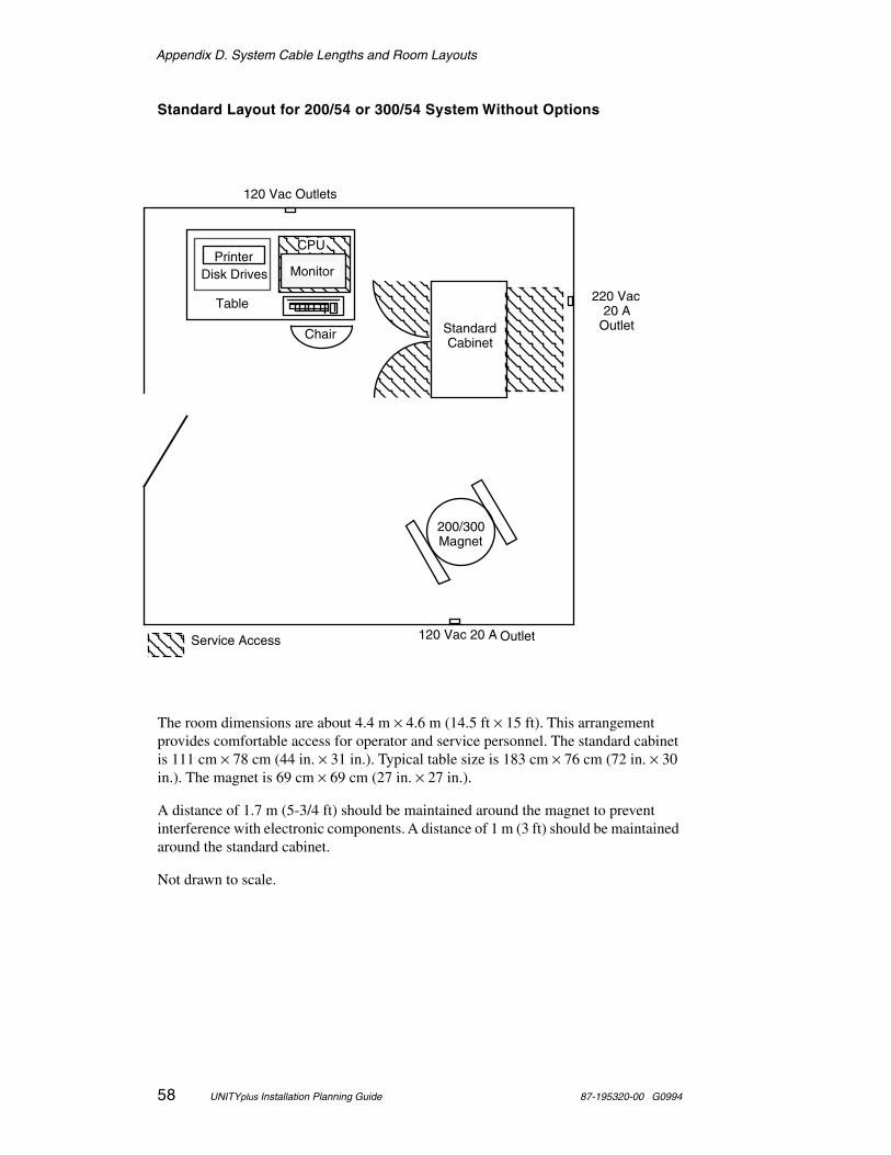
Appendix D. System Cable Lengths and Room Layouts
58 UNITYplus Installation Planning Guide 87-195320-00 G0994
Standard Layout for 200/54 or 300/54 System Without Options
The room dimensions are about 4.4 m × 4.6 m (14.5 ft × 15 ft). This arrangement provides comfortable access for operator and service personnel. The standard cabinet is 111 cm × 78 cm (44 in. × 31 in.). Typical table size is 183 cm × 76 cm (72 in. × 30 in.). The magnet is 69 cm × 69 cm (27 in. × 27 in.).
A distance of 1.7 m (5-3/4 ft) should be maintained around the magnet to prevent interference with electronic components. A distance of 1 m (3 ft) should be maintained around the standard cabinet.
Not drawn to scale.
120 Vac Outlets
120 Vac 20 A Outlet
220 Vac 20 A
Outlet
200/300 Magnet
Monitor
CPUPrinter
Disk Drives
Chair
Table
Standard Cabinet
Service Access
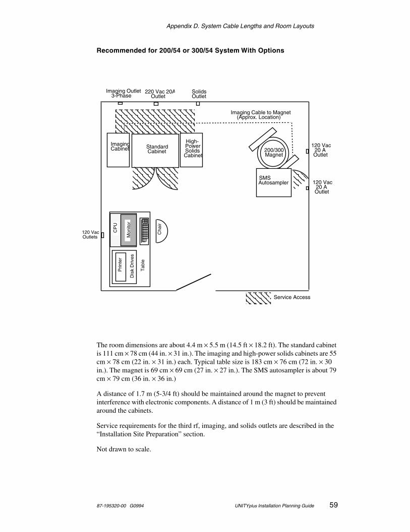
Appendix D. System Cable Lengths and Room Layouts
87-195320-00 G0994 UNITYplus Installation Planning Guide 59
Recommended for 200/54 or 300/54 System With Options
The room dimensions are about 4.4 m × 5.5 m (14.5 ft × 18.2 ft). The standard cabinet is 111 cm × 78 cm (44 in. × 31 in.). The imaging and high-power solids cabinets are 55 cm × 78 cm (22 in. × 31 in.) each. Typical table size is 183 cm × 76 cm (72 in. × 30 in.). The magnet is 69 cm × 69 cm (27 in. × 27 in.). The SMS autosampler is about 79 cm × 79 cm (36 in. × 36 in.)
A distance of 1.7 m (5-3/4 ft) should be maintained around the magnet to prevent interference with electronic components. A distance of 1 m (3 ft) should be maintained around the cabinets.
Service requirements for the third rf, imaging, and solids outlets are described in the “Installation Site Preparation” section.
Not drawn to scale.
Cha
ir
220 Vac 20A Outlet
Prin
ter
SMS Autosampler
Dis
k D
rives
CP
U
Service Access
120 Vac 20 A Outlet
120 Vac 20 A Outlet
120 Vac Outlets
Solids Outlet
Imaging Outlet 3-Phase
Imaging Cabinet
Imaging Cable to Magnet (Approx. Location)
Tab
leStandard Cabinet 200/300
Magnet
High- Power Solids Cabinet
Mon
itor
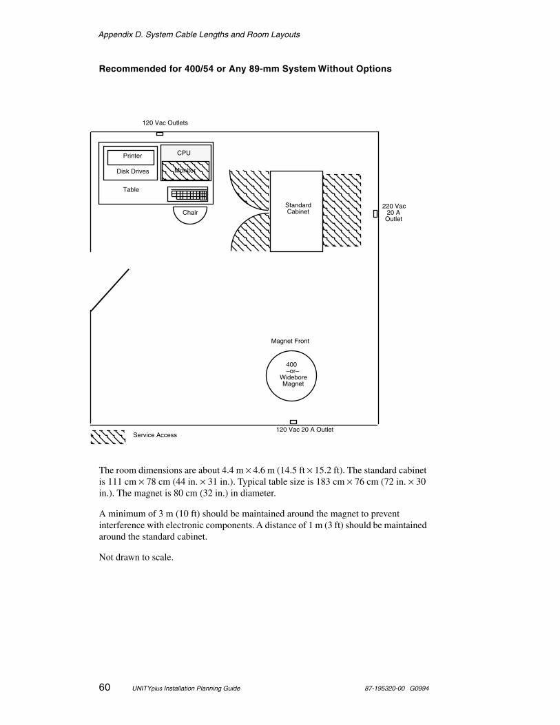
Appendix D. System Cable Lengths and Room Layouts
60 UNITYplus Installation Planning Guide 87-195320-00 G0994
Recommended for 400/54 or Any 89-mm System Without Options
The room dimensions are about 4.4 m × 4.6 m (14.5 ft × 15.2 ft). The standard cabinet is 111 cm × 78 cm (44 in. × 31 in.). Typical table size is 183 cm × 76 cm (72 in. × 30 in.). The magnet is 80 cm (32 in.) in diameter.
A minimum of 3 m (10 ft) should be maintained around the magnet to prevent interference with electronic components. A distance of 1 m (3 ft) should be maintained around the standard cabinet.
Not drawn to scale.
120 Vac Outlets
120 Vac 20 A OutletService Access
220 Vac 20 A
OutletChair
Printer
Disk Drives
CPU
Standard Cabinet
400 –or–
Widebore Magnet
Table
Monitor
Magnet Front
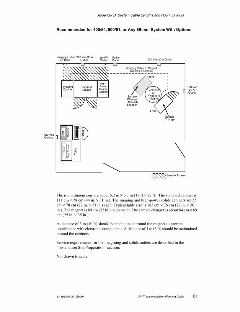
Appendix D. System Cable Lengths and Room Layouts
87-195320-00 G0994 UNITYplus Installation Planning Guide 61
Recommended for 400/54, 500/51, or Any 89-mm System With Options
The room dimensions are about 5.2 m × 6.7 m (17 ft × 22 ft). The standard cabinet is 111 cm × 78 cm (44 in. × 31 in.). The imaging and high-power solids cabinets are 55 cm × 78 cm (22 in. × 31 in.) each. Typical table size is 183 cm × 76 cm (72 in. × 30 in.). The magnet is 80 cm (32 in.) in diameter. The sample changer is about 64 cm × 69 cm (25 in. × 35 in.).
A distance of 3 m (10 ft) should be maintained around the magnet to prevent interference with electronic components. A distance of 1 m (3 ft) should be maintained around the cabinets.
Service requirements for the imagining and solids outlets are described in the “Installation Site Preparation” section.
Not drawn to scale.
120 Vac 20 A Outlet
Cha
ir
Sample Changer Alternate Location
Front
Sample Changer
Front
Service Access
Mon
itor
Prin
ter
Dis
k D
rives
120 Vac Outlets
120 Vac 20 A
Outlet
Imaging Outlet 3-Phase
Solids Outlet
220 Vac 30 A Outlet
Imaging Cable to Magnet (Approx. Location)
Tab
le
400/500 –or–
Widebore Magnet
Imaging Cabinet
High- Power Solids Cabinet
Standard Cabinet
3rd RF Outlet
CP
U
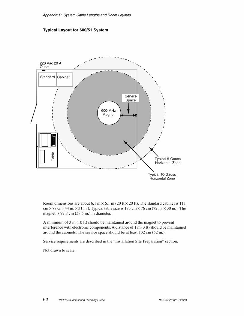
Appendix D. System Cable Lengths and Room Layouts
62 UNITYplus Installation Planning Guide 87-195320-00 G0994
Typical Layout for 600/51 System
Room dimensions are about 6.1 m × 6.1 m (20 ft × 20 ft). The standard cabinet is 111 cm × 78 cm (44 in. × 31 in.). Typical table size is 183 cm × 76 cm (72 in. × 30 in.). The magnet is 97.8 cm (38.5 in.) in diameter.
A minimum of 3 m (10 ft) should be maintained around the magnet to prevent interference with electronic components. A distance of 1 m (3 ft) should be maintained around the cabinets. The service space should be at least 132 cm (52 in.).
Service requirements are described in the “Installation Site Preparation” section.
Not drawn to scale.
Service Space
Typical 10-Gauss Horizontal Zone
Typical 5-Gauss Horizontal Zone
600-MHz Magnet
Standard Cabinet
Tab
le
220 Vac 20 AOutlet

Appendix E. Peripheral Compatibility
87-195320-00 G0994 UNITYplus Installation Planning Guide 63
Appendix E. Peripheral Compatibility
Explanation of Status Listing
Fully tested: Varian has fully tested this product and believes it to be fully compatible. Configuration and use of the product is documented in Varian manuals. We guarantee current compatibility, and every effort will be made to ensure compatibility with future products (e.g., future software releases).
Compatibility tested: Varian has performed a brief compatibility test of this product and knows of no incompatibilities, but does not support the product nor guarantee current or future compatibility.
Customer tested: At least one Varian customer has reported successfully using this product; no Varian experience.
Non-functional: Varian has reason to believe that this product will not work with our products.
Unknown: Varian has no experience with this product.
Printer and Plotter Compatibility
Hewlett-Packard ThinkJet (HP2225D)Description: Dot matrix printer/plotterRequired configuration: Serial interfaceStatus: Fully tested
Hewlett-Packard QuietJet (HP2227A)Description: Dot matrix printer/plotterStatus: Fully tested
Hewlett-Packard DeskJet Description: Ink jet printer/plotterStatus: Fully tested
Hewlett-Packard LaserJet III (HP33449A)Description: Laser printer/plotterRequired configuration: 2 MB memory expansionStatus: Fully testedComments: PostScript cartridge can be used and produces faster plotting.
Hewlett-Packard LaserJet 4 Description: Laser printer/plotterRequired configuration: Standard (2 MB memory)Status: Fully tested
IBM/Lexmark Color Jetprinter (PS 4079)Description: Inkjet printer/plotterRequired configuration: Standard (4 MB memory)Status: Fully tested
Appendix E. Peripheral Compatibility
64 UNITYplus Installation Planning Guide 87-195320-00 G0994
Hewlett-Packard HP7475 (HP7475A)Description: Single-sheet 11x17 plotterRequired configuration: Interface option 001 (RS-232C/CCITT)Status: Fully tested
Hewlett-Packard HP7550 (HP7550B)Description: 11x17 plotter with automatic sheet feedRequired configuration: B-size media handling kit (P/N 17092A) recommendedStatus: Fully tested
Hewlett-Packard DraftPro (HP7570A)Description: D-size (25x39) plotterStatus: Fully tested
Terminal Compatibility
GraphOn 240 (GO-240)Description: Monochrome terminalRequired configuration: Mouse (1001C-ET)Status: Fully tested
Tektronix 4207 (TEK 4207)Description: Color terminalRequired configuration: 3-button mouse (Option 4M)Status: Fully testedComments: 4205, 4107, 4105 also compatible but not recommended
Computer Compatibility
Sun SPARCsystem 600 MP seriesDescription: Sun multiprocessor server computersStatus: Compatibility testedComments: Tested as workstation only; status as host unknown. Tested
running SunOS 4.1.2

Appendix E. Peripheral Compatibility
87-195320-00 G0994 UNITYplus Installation Planning Guide 65
Terminal Emulator Compatibility
TextTerm+Graphics Description: Tektronix 4107/4207 emulator for Macintosh computersSource: Mesa Graphics, (505) 672-1998Status: Compatibility tested
VersaTerm ProDescription: Tektronix 4105 emulator for Macintosh computersStatus: Non-functional
X-Server Software Compatibility
MacX Description: X-server software for Macintosh computersSource: Apple ComputerStatus: Compatibility tested
eXodus Description: X-server software for Macintosh computersSource: White Pine Software, (603) 886-9050Status: Compatibility tested
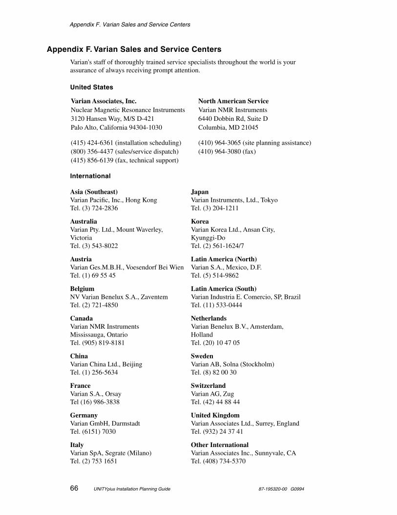
Appendix F. Varian Sales and Service Centers
66 UNITYplus Installation Planning Guide 87-195320-00 G0994
Appendix F. Varian Sales and Service Centers
Varian's staff of thoroughly trained service specialists throughout the world is your assurance of always receiving prompt attention.
United States
International
Varian Associates, Inc. North American ServiceNuclear Magnetic Resonance Instruments Varian NMR Instruments3120 Hansen Way, M/S D-421 6440 Dobbin Rd, Suite DPalo Alto, California 94304-1030 Columbia, MD 21045
(415) 424-6361 (installation scheduling) (410) 964-3065 (site planning assistance)(800) 356-4437 (sales/service dispatch) (410) 964-3080 (fax)(415) 856-6139 (fax, technical support)
Asia (Southeast) Varian Pacific, Inc., Hong KongTel. (3) 724-2836
JapanVarian Instruments, Ltd., TokyoTel. (3) 204-1211
AustraliaVarian Pty. Ltd., Mount Waverley, VictoriaTel. (3) 543-8022
KoreaVarian Korea Ltd., Ansan City, Kyunggi-DoTel. (2) 561-1624/7
AustriaVarian Ges.M.B.H., Voesendorf Bei WienTel. (1) 69 55 45
Latin America (North)Varian S.A., Mexico, D.F.Tel. (5) 514-9862
BelgiumNV Varian Benelux S.A., ZaventemTel. (2) 721-4850
Latin America (South)Varian Industria E. Comercio, SP, BrazilTel. (11) 533-0444
CanadaVarian NMR InstrumentsMississauga, OntarioTel. (905) 819-8181
NetherlandsVarian Benelux B.V., Amsterdam, HollandTel. (20) 10 47 05
ChinaVarian China Ltd., BeijingTel. (1) 256-5634
SwedenVarian AB, Solna (Stockholm)Tel. (8) 82 00 30
FranceVarian S.A., OrsayTel (16) 986-3838
SwitzerlandVarian AG, ZugTel. (42) 44 88 44
GermanyVarian GmbH, DarmstadtTel. (6151) 7030
United KingdomVarian Associates Ltd., Surrey, EnglandTel. (932) 24 37 41
ItalyVarian SpA, Segrate (Milano)Tel. (2) 753 1651
Other InternationalVarian Associates Inc., Sunnyvale, CATel. (408) 734-5370

Index
87-195320-00 G0994 UNITYplus Installation Planning Guide 67
Index
accessibility of site, 2acetone, 28air conditioning, 16, 22air freight delivery, 36air source, 21air ventilation, 17altitude, 17ambient temperature, 16ambient temperature ranges, 16antistatic spray, 23ASM-100 sample changer, 20
boiloff, 25building inspector, 18
cable lengths, 54, 55, 56cardiac pacemaker wearers, 8carpeting, 23cautions defined, 1CD-ROM unit, 31ceiling height, 5centerline to floor distance, 12codes, 18color CRTs, 8compatibility of peripherals, 63compressed air supply, 21computer preparation, 30configuring peripherals, 33CP/MAS option, 20, 22CP/MAS options, 19CRAMPS option, 20CRAMPS/multipulse module, 22crate unpacking, 37cryogenic equipment rack, 28
dataless client, 33daylight-savings time, 34degaussing coil, 29delivery of supplies, 2delivery responsibility, 1delivery services, 36Desktop SPARC manual set, 32dewars, 25differential amplifier box, 54, 55, 56distance
centerline to floor, 12documentation, 32domain name, 34domainname command, 34Doty probe, 21
electrical grounds, 19electrical outlets, 18electrical power surge protector, 29electrostatic discharge, 23equipment rack, 28external hard disk drive, 31
face mask, 28
floor coverings, 23floor structure strength, 6floor vibration, 8flowmeter, 27flutter tube, 28FOB block, 37
gate valve, 21gauss levels, 41G-force indicator, 37, 39gradient power cabinet, 19graphics boards, 31grounding, 23GX graphics, 31
hard disk default layout, 34hard disk drives, 31heat gun, 28helium gas supply, 27helium supplies, 1high altitudes, 16hoist, 28host computer, 30host computer and magnetic fields, 30hostname, 33humidity level, 16
imaging module, 22installation department, 39installation equipment, 24installation site preparation, 18installation site requirements, 2installation supplies, 24internal hard disk drive, 31Internet Protocol network address, 34IP address, 34isopropl alcohol, 28
laboratory size, 4ladder, 28lifting equipment, 2line conditioner, 18line voltage variation, 18liquid helium supply, 25liquid nitrogen supply, 26
magnet crate, 37, 39magnet field homogeneity, 8magnet transport, 36magnetic field considerations for computers, 30magnetic field exposure, 11magnetic field warning signs, 50magnetic interference, 4, 8man command, 32memory size, 31microimaging module, 19, 21modem connection, 23monitor degaussing coil, 29moving crates, 1, 39moving equipment, 36

Index
68 UNITYplus Installation Planning Guide 87-195320-00 G0994
moving the system, 37moving van delivery, 36
name service, 34NFS server, 33NIS or NIS+ server, 34nitrogen gas, 23nitrogen gas supply, 27nitrogen supplies, 1
Object Code License Form, 39oil filter, 21on-line documentation, 32opening crates, 37, 39operating frequency, 13Order Acknowledgement form, 37, 39
pacemaker hazard, 10PDU, 19peripheral compatibility, 63peripherals, 33
printers and plotters, 63terminals, 64
postdelivery checklist, 39postdelivery instructions, 37posting requirements, 50power conditioning system, 18power distribution unit, 19power line analyzer, 18power stick, 5predelivery checklist, 39prefilter, 21pregnancy hazard, 11preinstallation worksheet, 35preloaded SunOS, 31pressure gauge, 21printer and plotter compatibility, 63
receiving preparations, 36reproductive hazard, 11rf interference, 4, 13right-to-use license, 31room layouts, 54
safety precautions, meaning, 1sales centers, 66sample changer, 20scheduling installation, 39server, 33service centers, 66Ship By date, 39shipping crate damage, 37shipping damage, 37shipping method, 36signs, 50site survey, 39size of site, 4software compatibility, 30Solaris
collecting system and network information,33
versions compatible with VNMR, 30Solaris installation
preinstallation worksheet, 35solids modules, 19SPARCstation computers, 30standalone, 33step-down transformer, 18stray field plots, 10, 12, 41streaming tape cartridge, 30structural floor loading rating, 6subnet mask, 34Sun computer models, 30Sun computers, 30
architecture and SunOS versions, 30Sun operating system software (SunOS), 31Sun peripherals, 31SunExpress, 31SunOS
versions compatible with VNMR, 30SunOS and VNMR Software Installation Manual,
32SunOS and VNMR Software Installation Manual,,
31SunOS Media, 31supplies, 24supply dewars, 25surge protection, 18surge protector, 29System Operation Manual, 32
Techron gradient amplifiers, 19telephone jack, 23temperature stability, 16terminal compatibility, 64test equipment outlets, 20thermal gloves, 28third rf channel, 21tip-and-tell indicator, 37, 39transfer of ownership, 37transfer tube, 5, 25, 28
uname -n command, 33uncrating system, 4
van delivery, 36variable temperature accessory, 23Varian sales and service centers, 66ventilation, 17vertical magnetic fields, 11vibration in floor, 8vibration table, 20VME card cage, 19VNMR
compatibility with SunOS and Solaris, 30voltage variations, 18VT accessory, 26, 27
warning signs, 10, 50warnings defined, 1wideline module, 22
, 21world time zones, 34

Index
87-195320-00 G0994 UNITYplus Installation Planning Guide 69
ypcat hosts | grep `uname -n` command, 34ypwhich command, 34