univ. of tehranintroduction to computer network1 an introduction to computer networks university of...
TRANSCRIPT

Univ. of TehranIntroduction to Computer
Network 1
An IntroductionAn Introduction to to
Computer NetworksComputer Networks
University of TehranDept. of EE and Computer Engineering
By:Dr. Nasser Yazdani
Lecture 5: Physical LayerPhysical Layer
Univ. of TehranIntroduction to Computer
Network 2
Concepts: Data signal Links
Link functions Modulation Shannon’s Theorem Transmission media
OutlineOutline

Univ. of TehranIntroduction to Computer
Network 3
DataData Discrete data: an instance is binary.
Computer works with discrete data. Discrete is encoded in 0s and 1s.
Continuous data: change with time or space. It is converted to discrete data by
sampling Data is delivered by signals in the
links
Univ. of TehranIntroduction to Computer
Network 4
Link FunctionsLink Functions
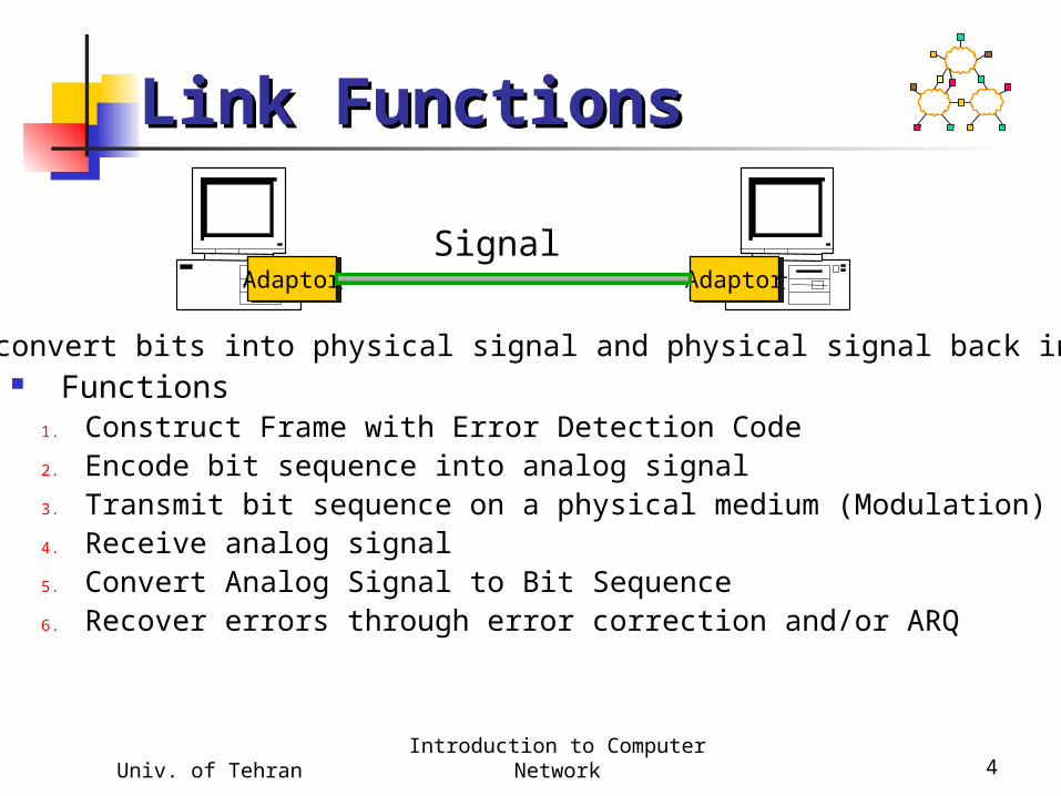
Functions1. Construct Frame with Error Detection Code2. Encode bit sequence into analog signal3. Transmit bit sequence on a physical medium (Modulation)4. Receive analog signal5. Convert Analog Signal to Bit Sequence6. Recover errors through error correction and/or ARQ
AdaptorAdaptor AdaptorAdaptorSignal
Adaptor: convert bits into physical signal and physical signal back into bits

Univ. of TehranIntroduction to Computer
Network 5
Link ComponentsLink Components
NRZI

Univ. of TehranIntroduction to Computer
Network 6
Link PropertiesLink Properties Function
Duplex/Half Duplex One stream, multiple streams
Characteristics Bit Error Rate Data Rate (this sometimes
mistakenly called bandwidth!) Degradation with distance
Univ. of TehranIntroduction to Computer
Network 7
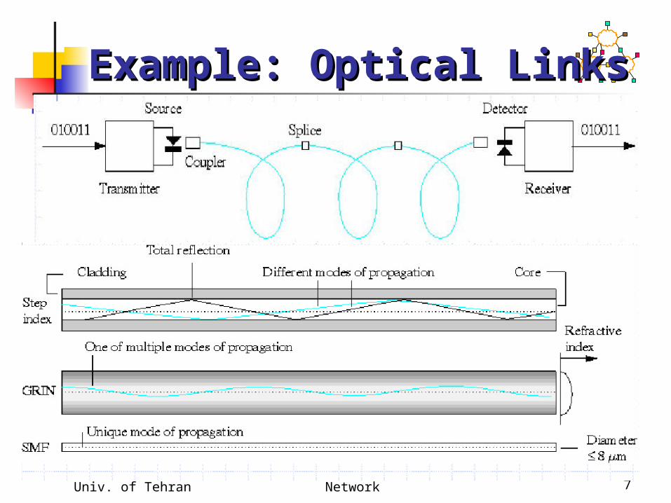
Example: Optical LinksExample: Optical Links
Univ. of TehranIntroduction to Computer
Network 8
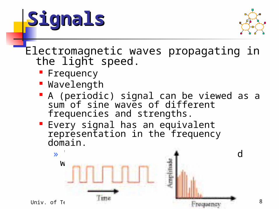
Electromagnetic waves propagating in the light speed. Frequency Wavelength A (periodic) signal can be viewed as a sum of sine
waves of different frequencies and strengths. Every signal has an equivalent representation in the
frequency domain.» What frequencies are present and what is their
strength (energy)
SignalsSignals

Univ. of TehranIntroduction to Computer
Network 9
Signals (cont)Signals (cont)
Univ. of TehranIntroduction to Computer
Network 10
Sender changes the nature of the signal in a way that the receiver can recognize.» Similar to radio: AM or FM
Digital transmission: encodes the values 0 or 1 in the signal.» It is also possible to encode multi-valued symbols
Amplitude modulation: change the strength of the signal, typically between on and off.» Sender and receiver agree on a “rate”» On means 1, Off means 0
Similar: frequency or phase modulation. Can also combine method modulation types.
Modulation Modulation
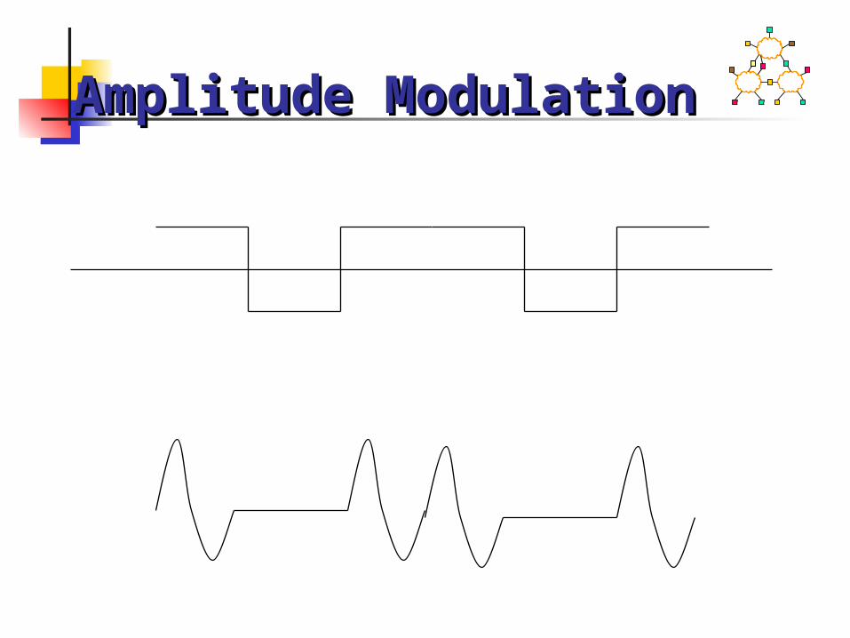
Amplitude ModulationAmplitude Modulation

Frequency ModulationFrequency Modulation
Baseband modulation: send the “bare” signal.
Carrier modulation: use the signal to modulate a higher frequency signal (carrier).
»Can be viewed as the product of the two signals
»Corresponds to a shift in the frequency domain
Baseband vs. Carrier Baseband vs. Carrier ModulationModulation

Am
plit
ud
e
Signal CarrierFrequency
Am
plit
ud
e
ModulatedCarrier
Amplitude Carrier Amplitude Carrier ModulationModulation
Univ. of TehranIntroduction to Computer
Network 15
ModulationModulation The function of transmitting the encoded
signal over a link, often by combining it with another (carrier signal) E.g. Frequency Modulation (FM)
Combine the signal with a carrier signal in such a way that the instantaneous frequency of the received signal contains the information of the carrier
E.g. Frequency Hopping (OFDM) Signal transmitted over multiple frequencies Sequence of frequencies is pseudo random
Univ. of TehranIntroduction to Computer
Network 16
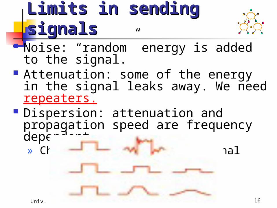
Noise: “random” energy is added to the signal.
Attenuation: some of the energy in the signal leaks away. We need repeaters.
Dispersion: attenuation and propagation speed are frequency dependent.» Changes the shape of the signal
Limits in sending Limits in sending signalssignals
Univ. of TehranIntroduction to Computer
Network 17
NoiseNoise A signal s(t) sent over a link is generally
Distorted by the physical nature of the medium This distortion may be known and reversible at the
receiver Affected by random physical effects
Shot noise Fading Multipath Effects
Also interference from other links Wireless Crosstalk
Dealing with noise is what communications engineers do
Univ. of TehranIntroduction to Computer
Network 18
Noise limits the link Noise limits the link rate rate
Suppose there were no noise E.g. Send s(t) always receive s(t+Δ) Take a message of N bits say b1b2….bN, and send a pulse
of amplitude of size 0.b1b2….bN Can send at an arbitrarily high rate This is true even if the link distorts the signal but in a
known way In practice the signal always gets distorted in an
unpredictable (random) way Receiver tries to estimate the effects but this lowers the
effective rate One way to mitigate noise is to jack up the power of
the signal Signal to Noise ratio (SNR) measures the extent of the
distortion effects

Univ. of TehranIntroduction to Computer
Network 19
Link rate and Distance Link rate and Distance
Links become slower with distance because of attenuation of the signal Amplifiers and repeaters can help
Univ. of TehranIntroduction to Computer
Network 20
Every transmission medium supports transmission in a certain frequency range. This is called channel capacity.» The channel bandwidth is determined by the transmission
medium and the nature of the transmitter and receivers A noiseless channel of width H can at most transmit a
binary signal at a rate 2 x H.» E.g. a 3000 Hz channel can transmit data at a rate of at most
6000 bits/second Assumes binary amplitude encoding Shannon extended this result by accounting for the
effects of noise. More aggressive encoding can increase the channel
bandwidth.» Example: modems
Channel capacityChannel capacity
Nyquist’s TheorumNyquist’s Theorum How is the data rate constrained by
bandwidth? Maximum data rate(bits/second) =
2 * bandwidth (hz)
Nyquist’s Theorum considers only the limit imposed by the bandwidth not noise, encoding, or other factors.
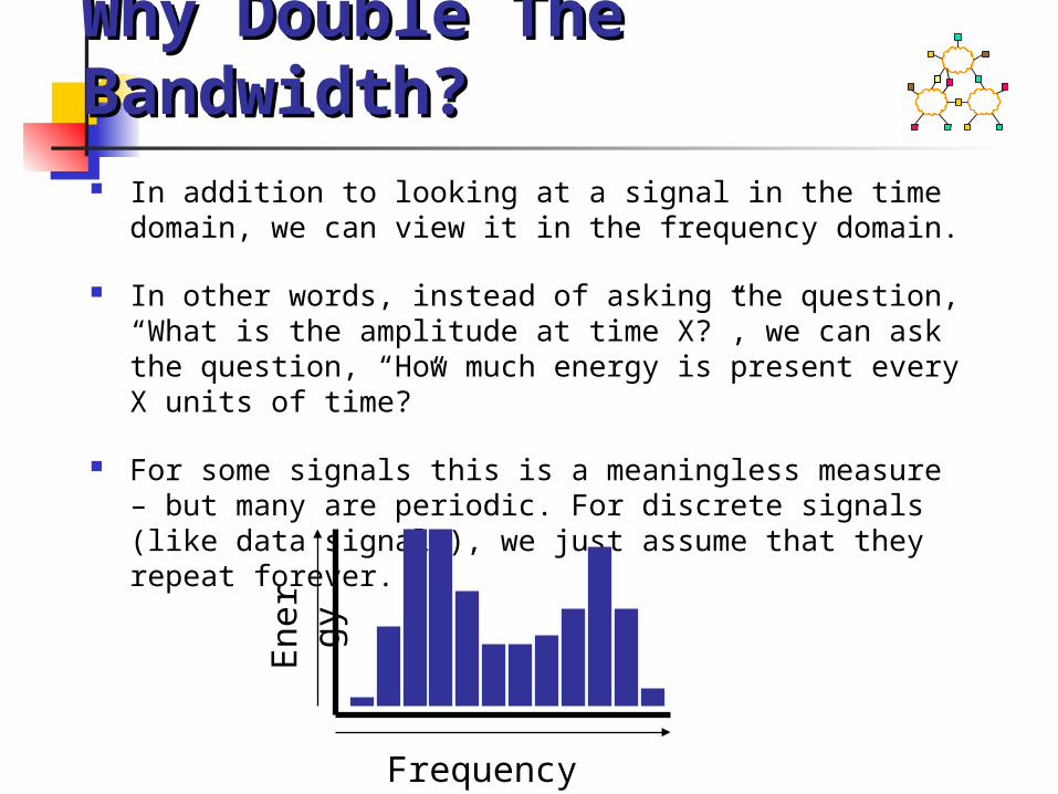
Nyquist’s TheorumNyquist’s Theorum Why Double The Why Double The Bandwidth?Bandwidth? In addition to looking at a signal in the time domain, we
can view it in the frequency domain.
In other words, instead of asking the question, “What is the amplitude at time X?”, we can ask the question, “How much energy is present every X units of time?”
For some signals this is a meaningless measure – but many are periodic. For discrete signals (like data signals), we just assume that they repeat forever.
En
erg
y
Frequency

Nyquist’s TheorumNyquist’s Theorum Why Double The Why Double The Bandwidth?Bandwidth?
As an analog signal is transmitted through some media, it is filtered by that media.
Not only is noise introduced, but energy at certain frequencies is lost – and nearly completely so above and below some threshold frequencies.
As a result, the signal has no harmonics above a certain frequency or below another.

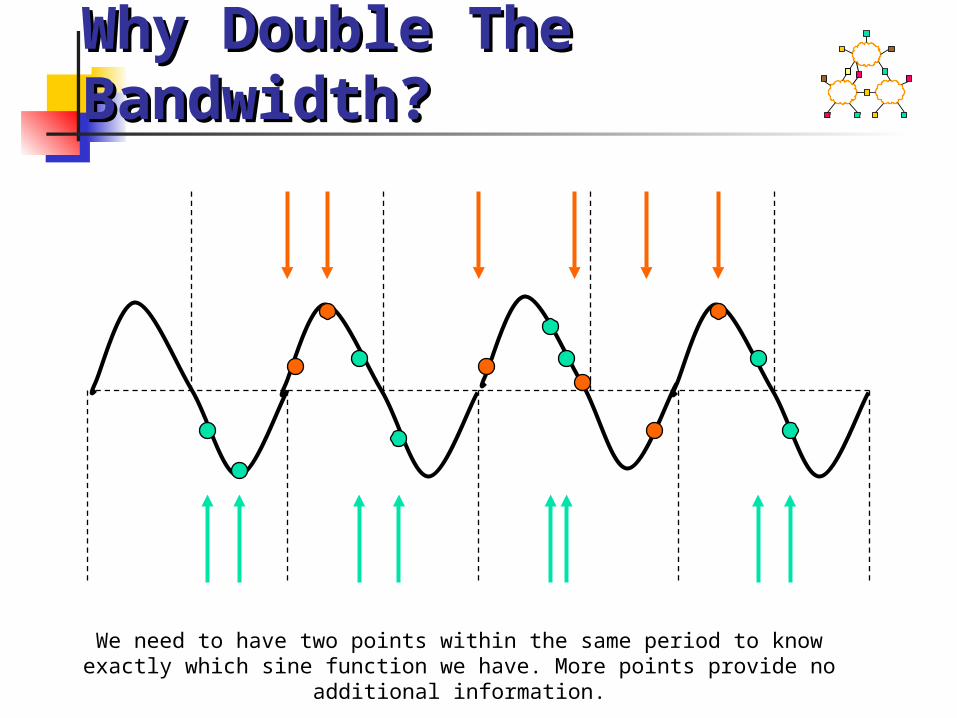
A fundamental theoretical finding is that to reproduce an analog signal accurately at a certain frequency, we must sample it twice as frequently. Otherwise, we could lose information.
If we sample less often, we might miss an event – we sample just before it happens.
If we sample more often, we just sample the same thing twice – we can’t get more information than is there – and the data has already been limited to a certain bandwidth of information.
Nyquist’s TheorumNyquist’s Theorum Why Double The Why Double The Bandwidth?Bandwidth?
Nyquist’s TheorumNyquist’s Theorum Why Double The Why Double The Bandwidth?Bandwidth?
We need to have two points within the same period to know exactly which sine function we have. More points provide no additional information.
Better Than Nyquist’s Better Than Nyquist’s LimitLimit
If clocks are synchronized sender and receiver, we only need one point per period.
This is because the synchronized starting point counts as one of the two points.

Noisy ChannelNoisy Channel Consider ratio of signal power to
noise power. Consider noise to be super-imposed
signal Decibel (dB) = 10 Log (S/N) S/N of 10 = 10 dB S/N of 100 = 20 dB S/N of 1000 = 30 dB
Shannon’s TheoremShannon’s Theorem Maximum data rate (bits/second) =
bandwidth (Hz) Log 2 (1 + S/N)
As before, this only gives us the limit on the data rate imposed by the noise, itself.
It does not consider the encoding or bandwidth limitations.
The bandwidth parameter can be confusing. It is there because it governs the effect that the noise has. More bandwidth either dilutes the noise, or gives the data more places to hide, or both.
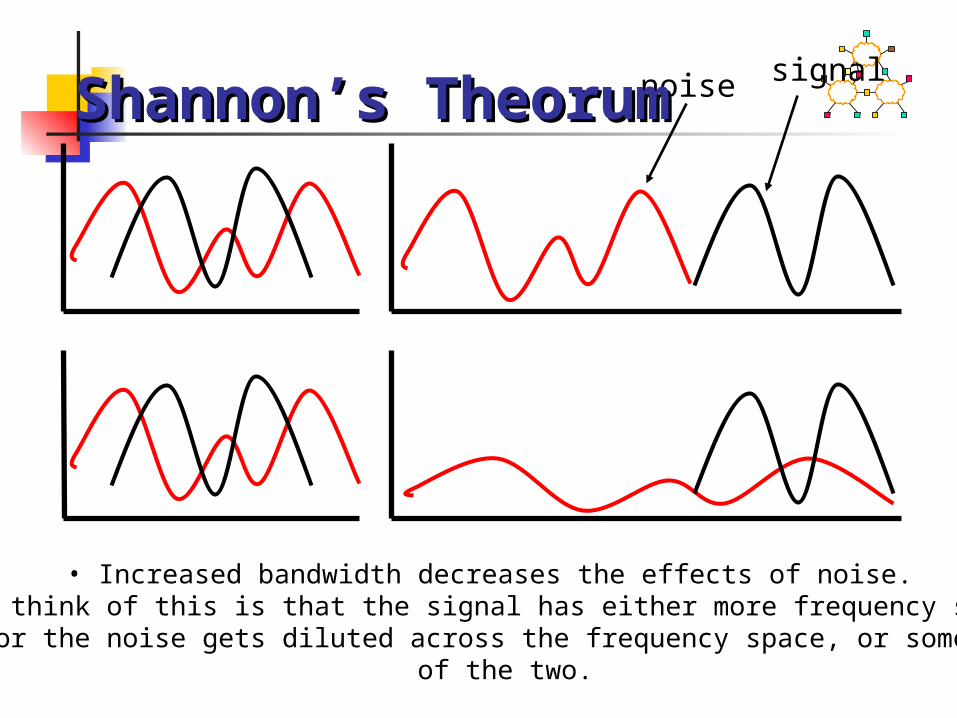
• Increased bandwidth decreases the effects of noise.• One way to think of this is that the signal has either more frequency space to call
its own, or the noise gets diluted across the frequency space, or some combination of the two.
noise signalShannon’s TheorumShannon’s Theorum

Higher Frequency = Higher Frequency = Higher EnergyHigher Energy
frequency = speed of light (m/s)/wavelength
(m) Energy (Joules) = frequency *
Plank’s constant Planck’s constant (Energy in a
photon) is 6.626 X 10 –34

Univ. of TehranIntroduction to Computer
Network 31
Signaling bits on a linkSignaling bits on a link Multi-level SignalingMulti-level Signaling
1
Levels
2
3
4
00 11 10 01 001
Levels
2345678
000 010 101 001 110
2-bits per symbol 3-bits per symbol
Ultimately, what limits the number of bits I can send per symbol?

Univ. of TehranIntroduction to Computer
Network 32
Maximum Maximum Capacity/Data RateCapacity/Data Rate
Shannon Capacity:
)/1(log2 NSBC Bandwidth of link Signal-to-Noise ratio
For example: Bandwidth of telephone link from telephone to a typical home is approx 3300Hz – 300Hz = 3kHz Signal-to-noise ratio is approx 30dB = 10log10(S/N) Therefore, C = 3000*log2(1001) ~= 30kb/s
Optical fiber has a higher capacity because the bandwidth, B, of a fiber is much greater than for wire; and it is less susceptible to noise,
N.
Univ. of TehranIntroduction to Computer
Network 33
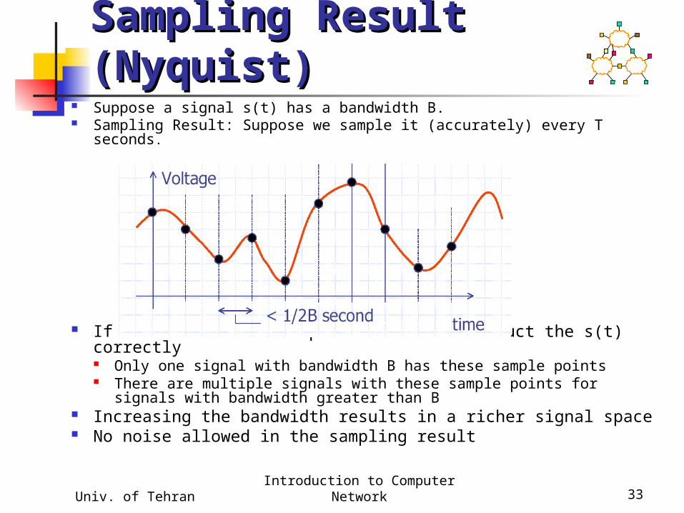
Sampling Result Sampling Result (Nyquist)(Nyquist)
Suppose a signal s(t) has a bandwidth B. Sampling Result: Suppose we sample it (accurately) every T seconds.
If T≤ 1/2B then it is possible to reconstruct the s(t) correctly Only one signal with bandwidth B has these sample points There are multiple signals with these sample points for signals
with bandwidth greater than B Increasing the bandwidth results in a richer signal space No noise allowed in the sampling result
Univ. of TehranIntroduction to Computer
Network 34
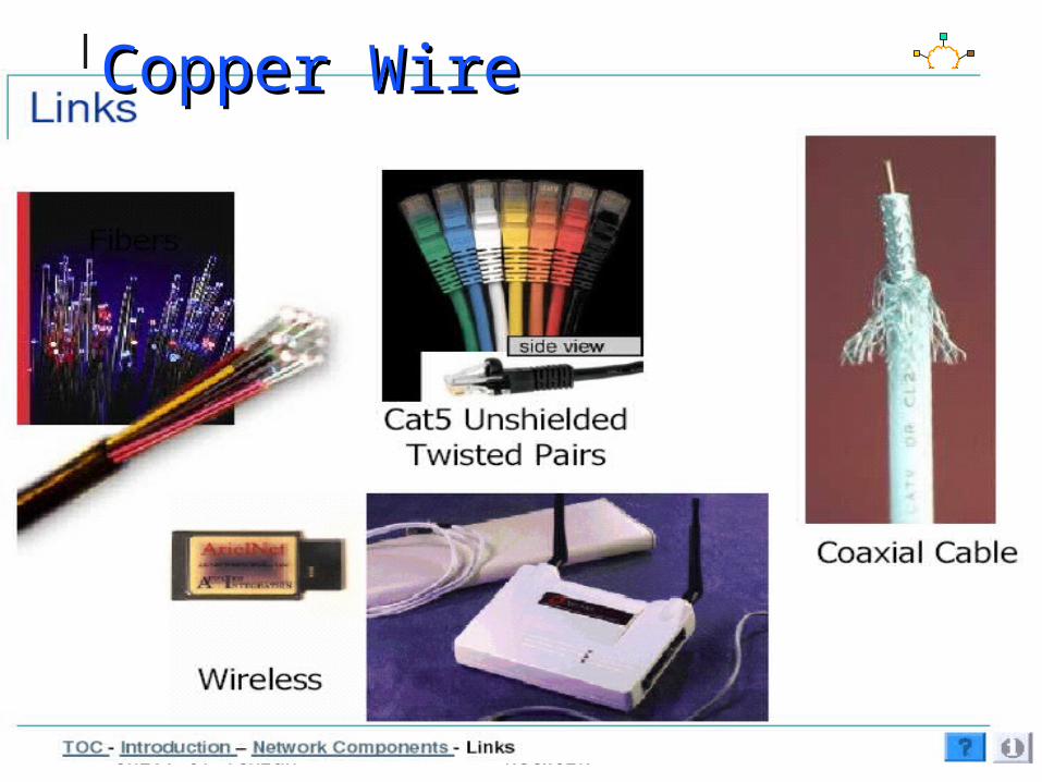
Unshielded Twisted Pair (UTP)» Two copper wires twisted - avoid antenna effect» Grouped into cables: multiple pairs with common
sheath» Cat 3 (voice grade) versus Cat 5 for data» 100 Mbps up to 100 m, 1 Mbps up to a few km» Cost: ~ 10cents/foot
Coax cables.» One connector is placed inside the other
connector» Holds the signal in place and keeps out noise» Gigabit up to a km
Copper WireCopper Wire
Univ. of TehranIntroduction to Computer
Network 35
Copper WireCopper Wire

Univ. of TehranIntroduction to Computer
Network 36
High frequency electromagnetic waves (>1GHz)Line of sight terrestrial transmissions and for
communications via satellites.Some atmospheric interference occurs but
reliable transmission can be obtained over distances up to 50 Km.
Microwaves is absorbed by rain and does not penetrate obstacles.
MicrowavesMicrowaves

lower indexof refraction
core
cladding
(note: minimum bend radius of a few cm)
Ray PropagationRay Propagation
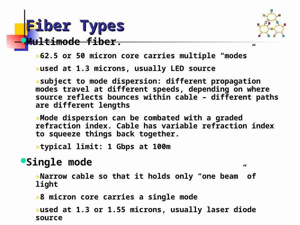
Multimode fiber.»62.5 or 50 micron core carries multiple “modes”
»used at 1.3 microns, usually LED source
»subject to mode dispersion: different propagation modes travel at different speeds, depending on where source reflects bounces within cable – different paths are different lengths
»Mode dispersion can be combated with a graded refraction index. Cable has variable refraction index to squeeze things back together.
»typical limit: 1 Gbps at 100m
Single mode»Narrow cable so that it holds only “one beam” of light
»8 micron core carries a single mode
»used at 1.3 or 1.55 microns, usually laser diode source
»typical limit: 1 Gbps at 10 km or more
»still subject to chromatic dispersion
Fiber TypesFiber Types

Univ. of TehranIntroduction to Computer
Network 39
Thin thread of glass or plasticLightweight.Fibers act as wave-guides for light which is usuallyproduced by lasers.Visible light has frequency around 5*10 15 Hz,which ensures an extremely high bandwidth.The raw materials are cheap.Immune to electrical interference.Difficult to join and tap.Security advantages
Fiber OpticFiber Optic
Univ. of TehranIntroduction to Computer
Network 40
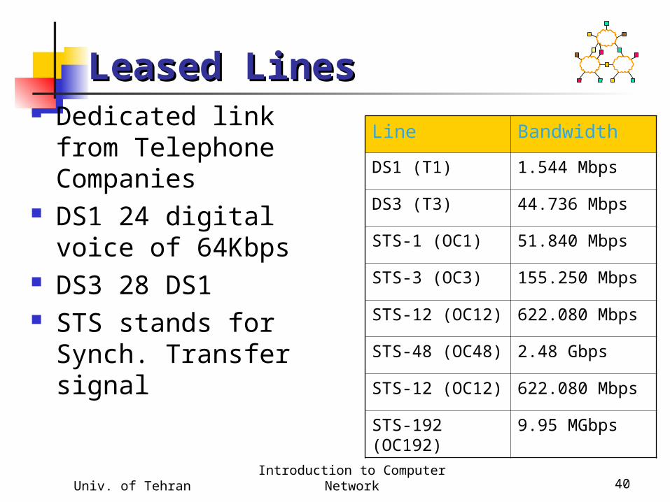
Leased LinesLeased Lines Dedicated link from
Telephone Companies DS1 24 digital voice
of 64Kbps DS3 28 DS1 STS stands for Synch.
Transfer signal
Line Bandwidth
DS1 (T1) 1.544 Mbps
DS3 (T3) 44.736 Mbps
STS-1 (OC1) 51.840 Mbps
STS-3 (OC3) 155.250 Mbps
STS-12 (OC12) 622.080 Mbps
STS-48 (OC48) 2.48 Gbps
STS-12 (OC12) 622.080 Mbps
STS-192 (OC192)
9.95 MGbps

Univ. of TehranIntroduction to Computer
Network 41
Last-Mile LinksLast-Mile Links Connect from home to
network service providers
xDSl (Digital Subscriber line), runs on local loop on telephone line. ADSL, VDSL
CATV- Cabel TV, BW of 6 MHZ, is asymmetric.
Line Bandwidth
POTS (modem) 28.8-65Kbps
ISDN 64-128 Kbps
XDSL 16Kbps-55.2 Mbps
CATV 20-40 Mpbs