univ.-prof. dr.prof. dr.-ing. otto heuneckeing. otto heunecke · univ.-prof. dr.prof. dr.-ing. otto...
TRANSCRIPT

Invited talk on calibration:Invited talk on calibration:
Univ.-Prof. Dr.-Ing. Otto HeuneckeUniv. Prof. Dr. Ing. Otto HeuneckeInstitute of Geodesy, University of the Bundeswehr Munich
The geodetic calibration line of the UniBw Munich Conception and implementation– Conception and implementation
11Wednesday, September 15, 2010

Outline
1. The new geodetic calibration line at NeubibergObj ti l i & d i- Objectives, planning & design
- Construction & side impressions
2. Determination and documentation of measurand „length“- Instruments & procedures& p
- Influence factor “meteorology”
- Calibration of low-cost meteo sensorsCalibration of low cost meteo sensors
- Use of geo sensor networks
Uncertainty of measurement: principles & implementation- Uncertainty of measurement: principles & implementation
3. Conclusion and outlook
22

1. The new geodetic calibration line at Neubiberg
Campus U i i f hUniversity of the
Bundeswehr Munich
530 m
33Further information on the University please see: www.unibw.de

Objectives
For the calibration of EDMs, tacheometers, levelling instruments, gyros etc.certified Geodetic Laboratories are obliged to: - Document and guarantee the traceability of the measurands (e.g. by intercomparison programmes);
- Document the obtained measurement uncertainty u of etalonsDocument the obtained measurement uncertainty u of etalons.
Geodetic calibration line UniBw Munich:
Primary measurands: Length and azimuth
Goals: udistance < 0.3 mm for distances up to 1100 m(better for shorter distances,see comparator of Geod.Lab.)
uscale < 0.2 ppm for distances up to 1100 m
uazimuth < 1 ´´
S C ff44
Secondary measurands: Coordinate differences

Design of calibration line
Schwendener Design 7 stations + 1 additional apart (P8)[m]
Shortest distance A 18.7Longest distance 1100.01st design parameter B 31,67 =1/15*(C-6A-U)Total length 7 stations C 590,3 =6A+15B+36D2nd design parameter D 0,08333 =1/36*UEDM half wave length U 3
P1 P2 P3 P4 P5 P6 P7 P8
55

Distribution of distances over length
0
Distribution of possible distances over total baseline
0
0
0
0
0
Min. 18.7 m Max. 1100.0 m
0
00 200 400 600 800 1000
0
0
0
Distance [m]
2 1 + 7 = 28 measureable distances
66

Distribution of distances over EDM half wave length
m[m/s] MHz MHz
[ / s]M
MM
cU ff
15 1002 2 1
EDM half wave length
Examples:fM = 50 MHz fM = 30 MHz
Distribution over U = 3 m (design parameter)
Distribution over U = 5 m
0
0
0
0
0
0
0
0
0
0
0
0,0 0,5 1,0 1,5 2,0 2,5 3,00
0
0
0
0 1 2 3 4 5
0
0
0
0
0
0
0
0
77
0
Half wave length [m]0
Half wave length [m]

Construction of measurement pillars
88

Construction details
Container for t
Measurement pillar No. 12 pillars for
additional
permanent measurement setups
(230 V, Internet)
99
equipment

Impressions from construction works in 2008
1010

Impressions from recent status
1111

Measurand “azimuth”
Leica TCM 1800Gyro azimuth
Gyromat 2000
Presentation is focused on measurand length“ only!System „Icarus“
Presentation is focused on measurand „length only!
- Astronomical azimuth (pole star)- Deflection of the vertical
1212GNSS azimuth

Equipment of Geodetic Laboratory
30 m interferometric longitudinal comparator:- Interferometer HP 5507B- Measurement uncertainty u=(0.6 +1.0L[m]) m
Climate chamber:
[m]- Air-conditioned environments
1313
- Temp. band -25°C – +45°C- Aligned with comparator

Instruments for high quality distance measurements
Leica TDA 5005Kern Mekometer 5000 Leica AT901-LR
L i AT401Leica System 1200 Leica AT401
1414

2. Determination of measurand „length“ by EDM
*Y
Meteorology
*Y
Y* : Uncorrected raw“ observation
Niemeier, W.:Zur Zuverlässigkeit geodätischer Systeme – Problemformulierung und Lösungsansätze.
Y* : Uncorrected „raw observation
1515
Zur Zuverlässigkeit geodätischer Systeme Problemformulierung und Lösungsansätze.Wiss. Arbeiten der Fachrichtung Vermessungswesen, Nr. 153, Hannover, 1989

Functional and stochastical model of evaluation
* *,1 1
p q
j jj j
Y Y c r f Y
XFunctional model:
Each correction is a function of some influence factors Xi , i = 1, … N , e g temperature and adds a respective percentage to the variance of the resulte.g., temperature and adds a respective percentage to the variance of the result. Even “centering” etc. can be seen as a correction cc with E(cc) = 0 and c
2.
2raw
XXN N
O
O
Stochastical model: Co-variance matrix of influence factors
,N N
*,2 2 TY XX
f Y
XF F FVariance of result Y :
1616
,Y raw XX F F F
XVariance of result Y :

Guide to the expression of uncertainty in measurement
Produced by:Joint Committee for Guides in Metrology
Download of documents see:
1717
www.bipm.orgBureau International des Poids et Mesures

Basic terms and definitions – GUM in brief
Uncertainty of measurement u:Parameter, associated with the result of a measurement, that characterizes the dispersion of the values that could reasonably be attributed to the measuranddispersion of the values that could reasonably be attributed to the measurand.
Uncertainty of measurement comprises many components. Some of these components may be evaluated from the statistical distribution of the results p yof series of measurements and can be characterized by experimental standard deviations. The other components, which also can be characterized by standard deviations, are evaluated from assumed probability distributionsby standard deviations, are evaluated from assumed probability distributions based on experience or other information.
Principles to obtain u :Principles to obtain u :- Analytical deduction (law of error propagation, Bayes theorem);- Numerical studies: Monte-Carlo-Simulation (see JCGM 101:2008);Numerical studies: Monte Carlo Simulation (see JCGM 101:2008);- Intercomparison programmes and their combined evaluation.
1818
Essential: Consideration of influence factors Xi , i = 1, … N ; N : complete.

Graphical illustration of values, error, and
t i tuncertaintySee JCGM 100:2008,Annex D, p. 53Annex D, p. 53
C l t ltComplete result:
;f f 2
Y k u
1919
: factor, often 2k k

Influence of meteorological correction on EDM
ìïïïïí
dt : variation of temperature [°C]
dp : variation of air pressure [hPa] 610 1 00 0 28 0 04d dt d d íïïïïî
de : variation of partial water vaporpressure [hPa], with
[%]rF
. . .610 1 00 0 28 0 04dn dt dp de
î
rF : rel. humidity, E : saturation vapor
100[%]rFe E=
y, p
Demand for 0.1 ppm:ith 0 1°C ith 0 3 hP F ith 10% t ti f i l th t d!t with 0.1°C, p with 0.3 hPa, rF with 10% representative for signal path requested!
1 2 3 4 5 6 7 8
2020
Alignment of 20 units for integral determination of t , p and rF

Principle of geo sensor networks
2121

Crossbow mote with sensor board MT420
Mote with integrated devices:- 1 Dual axis accelerometer- 1 Light sensor www xbow com1 Light sensor- 1 Barometer- 1 Temperature- und humidity measuring unit
1 L t GPS i
www.xbow.com
- 1 Low-cost GPS receiver
- 64 Kbyte EEPROM, TinyOS & ISM radio moduleapprox. 3 x 5 x 4 cm
Light sensor
- Type TAOS TSL2550D
Accelerometer
- Type ADXL202JE (MEMS Technology)
- Range 400–1000 nm- 1 channel for IR- 1 channel visible light
- Range ±2 g - Resolution 2 mg
Rate 60 Hz - 1 channel visible light- 12 bit resolution
„Lux to bit“
- Rate 60 Hz- Nonlinearity 0.2%- “Zero g bias level 2.0 mg/°C from 25°C“
t i
22222222www.analog.com
www.taosinc.com

Meteo sensors at Crossbow board MT420
Barometer
- Type Intersema MS5534AM
Temperature- and humidity meas. unit
- Type Sensirion SHT11- Range 300 – 1100 hPA- Resolution 0,01 hPA- Accuracy ± 1 5% at 25°C“ ca. 7,5 x 5 x 2,5 mm„Accuracy ± 1.5% at 25 C
Temperature:Range 40 to + 80°C
ca. 7,5 x 5 x 2,5 mm
- Range -40 to + 80 C- „Accuracy ± 0.5°C at 25°C“
Humidity: ca. 3 mm
y- Range 0 – 100% Rel. humidity (RH)- Resolution 0,3% RH
Absolute RH accuracy ± 3 5% RH“www.intersema.ch
- „Absolute RH accuracy ± 3.5% RH“
www.sensirion.com
23232323

Location unit at Crossbow board MT420
- GPS 16 channels L1 C/A Code- Rate 4 Hz
www u-blox com- NMEA output, support DGPS & WAAS- External antennaAccuracy Position 2 5m CEP according
www.u-blox.com
- Accuracy Position 2.5m CEPDGPS 2.0m CEP
according μBlox
Ca. 17 x 22.4 x 3 mm
Accuracy specifications of Crossbow meteorological units:t with 0.5 °C, p with 1.5 hPA, rF with 3.5% at 25°C
Low-cost sensors for high accuracy application?Goal: Enhancement by factor 5 by calibration with respect to t and p .
2424
Goal: Enhancement by factor 5 by calibration with respect to t and p .

Recording of reference values for calibration
Quartz thermometer 2804A
t
Universal meteo unit Almemo 2590-3S
t Ft, p, rF
Climate chamber
Thommen-Meteo-Station HM30
t, p, rF Digiquarz
B t 760Barometer 760p
25252525Reference instruments by factor 10 better then crossbow MT 420 test items

Investigations with respect to t
35Temperaturverhalten zu Referenztemperaturen
1
2
T = 1 min.
25
30
2
3
5
6
20
n °C
8
9
10
11
Motes
10
15
Tem
pera
tur i
12
13
14
15
= 0.5 °C= 0.1 °C
5
10 15
18
19
20
Reference
5
071
Referenz
26262626
0 100 200 300 400 500 600-5
Zeit in min

Investigations with respect to p
966
968Druckverhalten zu Referenzdruck
1
2
T = 1 min.
962
964
3
5
6
8
= 0.3 hPA = 1.5 hPA
958
960
ck in
hP
a
9
10
11
12
Reference
954
956
Dru
c
13
14
15
18
950
95219
20
71
Referenz
0 100 200 300 400 500 600948
Zeit in min
2727
Pressure units depict a certain dependence to temperature.

Investigations with respect to rF
90Feuchteverhalten zu Referenzfeuchte
1
2Reference
T = 1 min.
70
80
2
3
5
6
8
Reference
= 10 % = 3.5 %
60
hte
in %
9
10
11
12
40
50Feuc
h 13
14
15
18
19
30
40 19
20
71
Referenz
0 100 200 300 400 500 60020
Zeit in min
Rel humidity at climate chamber varies due to regularization of temperature
2828
Rel. humidity at climate chamber varies due to regularization of temperature.
Noticeable time lag of humidity units.
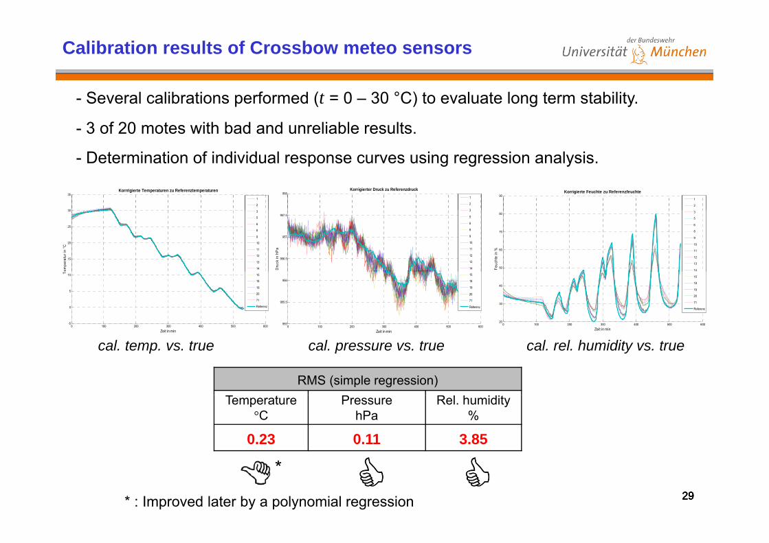
Calibration results of Crossbow meteo sensors
- Several calibrations performed (t = 0 – 30 °C) to evaluate long term stability.
- 3 of 20 motes with bad and unreliable results.
- Determination of individual response curves using regression analysis.
30
35Korrrigierte Temperaturen zu Referenztemperaturen
1
2
958Korrigierter Druck zu Referenzdruck
1
2
3
90Korrigierte Feuchte zu Referenzfeuchte
1
2
15
20
25
30
empe
ratu
r in
°C
3
5
6
8
9
10
11
12
13
14
956.5
957
957.5
Dru
ck in
hP
a
3
5
6
8
9
10
11
12
13
14 50
60
70
80
Feuc
hte
in %
3
5
6
8
9
10
11
12
13
14
0 100 200 300 400 500 600-5
0
5
10
Zeit in min
T
15
18
19
20
71
Referenz
0 100 200 300 400 500 600955
955.5
956
Zeit in min
15
18
19
20
71
Referenz
0 100 200 300 400 500 60020
30
40
Zeit in min
15
18
19
20
71
Referenz
RMS (simple regression)
cal. temp. vs. true cal. pressure vs. true cal. rel. humidity vs. true
Temperature °C
PressurehPa
Rel. humidity%
0.23 0.11 3.85
29292929
*
* : Improved later by a polynomial regression

Determination of reference distances by ME 5000
Kern Mekometer ME 5000Kern Mekometer ME 5000- Variable frequency 460 – 510 MHz - U = 0.3 m (half wave length)A 0 2 0 2
Set up ofCrossbow motes
3030
- Accuracy: 0.2 mm + 0,2 ppm- Range: 5000 m
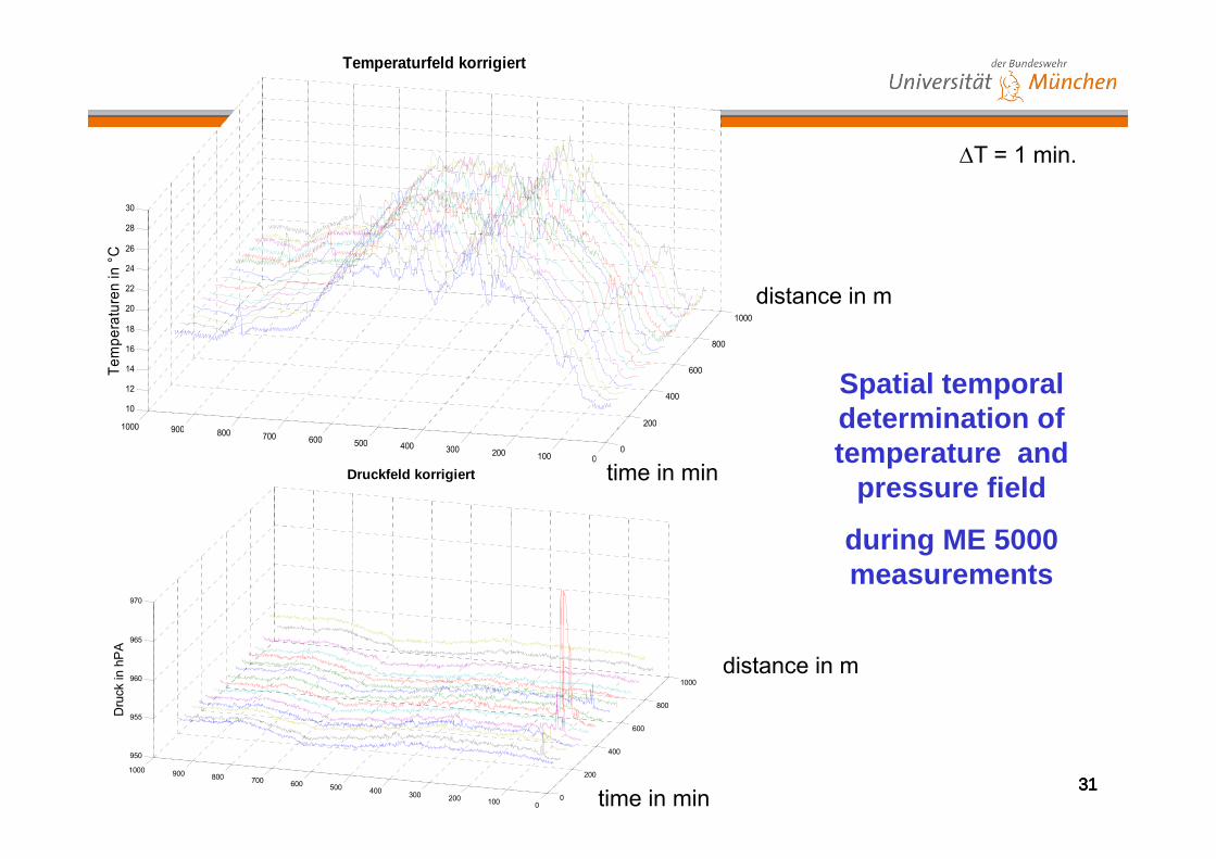
Temperaturfeld korrigiert
28
30
T = 1 min.
100018
20
22
24
26
erat
uren
in °
C
distance in m
200
400
600
800
8009001000
10
12
14
16
Tem
pe
Spatial temporal determination of
00100200300400500600700800900000
Entfernung in mZeit in min time in minDruckfeld korrigiert
temperature and pressure field
970
during ME 5000 measurements
800
1000
955
960
965
Dru
ck in
hP
A
distance in m
313131310
200
400
600
01002003004005006007008009001000
950
Entfernung in mtime in min

Uncertainty budget ME 5000
Influence factor XiAssumption for
distribution Influence Measurement uncertainty u
Addi i l l f i l dditi 0 14Additional value of instrument normal additive 0,14 mm
Scale factor of instrument normal proportional 0,50 ppm
Meteorological correction normal proportional 0,14 ppm
Eccentricity of prism rectangle additive 0,02 mmEccentricity of prism g ,
Resolution of instrument rectangle additive 0,02 mm
Inclination of prism rectangle additive 0,03 mm
Misalignment of prism normal additive 0,005 mm
Uncertainties of additional value uc and scale factor us are from the old calibration line.
Uncertainty of scale factor is dominant (and must be improved)!
3232
Influence of meteorological correction relatively low compared to uc and us .

Determination of reference distances by AT901-LR
Absolute distance measurement (ADM), interferometric distance measurement (IFM)
S ifi d t t i t ADMSpecified measurement uncertainty ADM: Distance: U = 10 m + ppm?Modulation frequency: 900 MHzMax. range: 80 m (volume 160 m)
- New and certified instrument- Re-calibrated according to NIST at Geodetic LabRe calibrated according to NIST at Geodetic Lab.
From a Leica brochure:
Leica laser tracker AT901-LR
3333
MPE: Maximum permissible error
Approx.: MPE = U = 2 u

Possible configurations for AT901-LR
Simplified functional model:
2 1Y Y Y
1 2Y Y Y 1 2Y Y Y
Use of intermediate points if Yi > 75 m (out door situation):
3434

Uncertainty budget AT901-LR
Influence factor XiAssumption
for distribution Influence Measurement uncertainty u
Additional value of instrument normal additive 5 µm
Scale factor of instrument normal proportional ???
Meteorological correction normal proportional 0,14 ppm
Production accuracy corner cube:circularity rectangle additive 2 µmcircularity
Production accuracy corner cube:surface rectangle additive 3 µm
Error of alignment rectangle additive 5 µmStability set up rectangle additive 6 µmg
Meteorological conditions are most crucial for measurement uncertainty of AT901-LR.Uncertainty budget much better than ME 5000.
3535
Scale factor of instrument uncertainty actually not considered.Unfavorable error propagation for set ups with intermediate points.

Preliminary results
DistanceEstimated value
[m]
Measurement uncertainty u
ME 5000 [mm]
Measurement uncertainty u
AT901-LR [mm][ ] ME 5000 [mm] AT901-LR [mm]
1-2 18,78??? 0,295 0,016
2-3 82,45??? 0,295 0,023
3 4 146 14??? 0 300 0 0293-4 146,14??? 0,300 0,029
4-5 177,97??? 0,305 0,063
5-6 114,29??? 0,298 0,026
6-7 50,62??? 0,297 0,017
7-8 509,69??? 0,432 0,120
3636
, , ,

3. Conclusion and outlook
- Results obtained so far at the calibration line UniBw Munich are only preliminary.
- Intercomparison programmes with participation of several geodeticinstitutions ongoing and open to any other interesting party.
W k h th fi l lt d ibiliti f th lib ti- Workshop on the final results and possibilities of the new calibration line scheduled for Spring 2011.
- Documentation of complete results according to GUM is obligatory forGeodetic Laboratories – and also any other metrology institutions.
- Principles of GUM are known in Geodesy since years, but a full adaption is still outstanding.
C id ti f ll l t i fl f t th i t ti- Consideration of all relevant influence factors on the interestingmessurands is essential in today’s metrology; see meteorology on EDM’s.
3737
Thank you very much for the invitation!Thank you very much for the invitation!