univer - mechanical & manual valves - series ch/ai/ac/al/az · 2/2-3/2-5/2 mechanical &...
TRANSCRIPT

Tech
nica
l mod
ifica
tions
kee
p in
res
erve
!(2
011/
01)
+32 3 355 32 20 1.22.01
2/2-3/2-5/2 MECHANICAL & MANUAL VALVES (M5-1")Series CH/AI/AC/AL/AZ
4
Popp
et v
alve
s
die-cast zamaknitrile rubber
zinc-plated steel/technopolymernickel-plated brass
Valve bodySealsActuatorsSpool
-10 ÷ +45 °C max + 50 °C
fi ltered air 50 μm, lubricated or notpoppet system
2/2 NC, 3/2 NC, 2/2 NO, 3/2 NO max 10 bar
manual, mechanicalmechanical spring
G1/85 mm
NC = 600 NO = 550
Ambient temperatureFluid temperatureFluidCommutation systemWays/PositionsPressureControlReturnConnectionsNominal Ø Nominal fl ow rate (Nl/min)
TECHNICAL CHARACTERISTICS
CONSTRUCTIVE CHARACTERISTICS
Flow rate characteristics
P (bar)
Qn (Nl/min)
PA (bar)
>> 3/2 NC
2
4
6
8
10
0 500 1000 1500 2000
4
2
8
6
10
P (bar)
Qn (Nl/min)
PA (bar)
>> 3/2 NO
2
4
6
8
10
0 500 1000 1500
2
8
6
10
4
2000
= Working pressure= Supply pressure= Flow rate
PPAQn
Main features:- closed centers- high fl ow rate- quick response timeSuitable for heavy duties and where the number of mechanical operation is high.
2/2 - 3/2 G1/8 poppet valves
CH

Tech
nica
l mod
ifica
tions
kee
p in
res
erve
!(2
011/
01)
+32 3 355 32 201.22.02
UNIVER GROUP2/2 - 3/2 G1/8 poppet valvesCH
Symbol Part no.Flow rate(Nl/min)
ForceN
WeightKg
Roller lever - spring
2/2 NC
3/2 NO
2/2 NO
3/2 NC 600
600
550
550
21
21
15
15
CH-250
CH-252
CH-254
CH-256
0,2
0,2
0,2
0,2
= Supply port= Use= Exhaust= Control= Return
12 3
1210
Symbol Part no.
Uni-directional roller lever - spring
= Supply port= Use= Exhaust= Control= Return
12 3
1210
2/2 NC
3/2 NO
2/2 NO
3/2 NC
Flow rate (Nl/min)
600
600
550
550
ForceN
16
16
12
12
CH-260
CH-262
CH-264
CH-266
WeightKg
0,21
0,21
0,21
0,21
Tech
nica
l mod
ifica
tions
kee
p in
res
erve
!(2
011/
01)
1.22.03
UNIVER GROUP2/2 - 3/2 G1/8 poppet valvesCH
Symbol Part no.
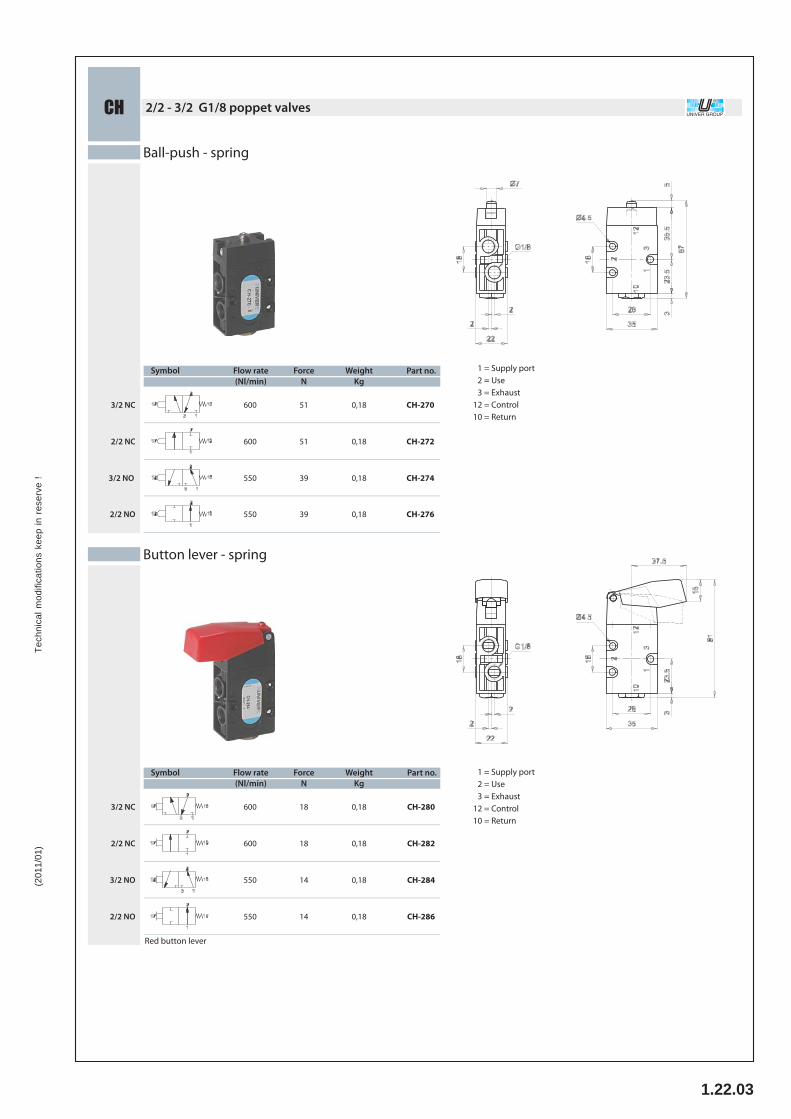
Ball-push - spring
2/2 NC
3/2 NO
2/2 NO
3/2 NC CH-270
CH-272
CH-274
CH-276
Flow rate(Nl/min)
ForceN
WeightKg
600
600
550
550
51
51
39
39
0,18
0,18
0,18
0,18
= Supply port= Use= Exhaust= Control= Return
12 3
1210
Symbol Part no.
Button lever - spring
2/2 NC
3/2 NO
2/2 NO
3/2 NC CH-280
CH-282
CH-284
CH-286
Flow rate(Nl/min)
ForceN
WeightKg
600
600
550
550
18
18
14
14
0,18
0,18
0,18
0,18
Red button lever
= Supply port= Use= Exhaust= Control= Return
12 3
1210

Tech
nica
l mod
ifica
tions
kee
p in
res
erve
!(2
011/
01)
+32 3 355 32 201.22.04
4Po
ppet
val
ves
- Light with compact design- Low operating force and high response time - M5 threaded connections or push-in fi tting tube Ø4 - Wide range of actuators and manual overrides for mounting panel (Original Univer)
-10 ÷ +90 °Cmax +50 °C
fi ltered air 50 μm, lubricated or notpoppet system
2/2 NC, 3/2 NC, 2/2 NO, 3/2 NOmax 10 bar
manual, mechanicalmechanical spring
M5, tube Ø42,5 mm
98 Nl/min
Ambient temperatureFluid temperatureFluidCommutation systemWays/PositionsPressureControlReturnConnectionsNominal Ø Nominal fl ow rate (Nl/min)
Flow rate characteristics
4
6
8
10
0 50 100 150 200 250
2
4
6
8
10
2
P (bar)
Qn (Nl/min)
PA (bar)
AI JETPneumatic switches JET series
TECHNICAL CHARACTERISTICS
zamaknitrile rubber
nickel-plated brass
Valve bodySealsSpool
CONSTRUCTIVE CHARACTERISTICS
OTHER VERSIONS AVAILABLE
= Working pressure= Supply pressure= Flow rate
PPAQn

Tech
nica
l mod
ifica
tions
kee
p in
res
erve
!(2
011/
01)
1.22.05
Ball-push - spring M5
3/2 NC
3/2 NO
AI-9000M
AI-9010M
AI-9020M2/2 NC
2/2 NO
M5
M5
M5
M5 AI-9030M
14 0,060
0,060
0,060
0,060
14
14
14
Symbol Connection Part no.WeightKg
Force (a)N
A B C
1 =2 =3 =
Supply portUseExhaust
Pre-strokeA
B Maximum opening
C Total stroke
(b)
Roller lever - spring M5
M5
M5
M5
M5
AI-9100M
AI-9110M
AI-9120M
AI-9130M
0,085
0,085
0,085
0,085
3/2 NC
3/2 NO
2/2 NC
2/2 NO
B C
B Maximum opening
C Total stroke
1 =2 =3 =
Supply portUseExhaust
7
7
7
7
Symbol Connection Part no.WeightKg
Force (a)N
(b)
Uni-directional roller lever - spring M5
Symbol
M5
Connection
M5
M5
M5
Part no.
AI-9200M
AI-9210M
AI-9220M
AI-9230M
3/2 NC
3/2 NO
2/2 NC
2/2 NO
WeightKg
0,085
0,085
0,085
0,085
B C
B Maximum opening
C Total stroke
1 =2 =3 =
Supply portUseExhaust
4
4
4
4
Force (a)N
(b)
(a) = at 6 bar (b) = upon request 2/2 NO version
UNIVER GROUPPneumatic switchesAI_JET

Tech
nica
l mod
ifica
tions
kee
p in
res
erve
!(2
011/
01)
+32 3 355 32 201.22.06
Mechanical push button with screw mounting - spring M5
AI-9300M
AI-9310M
AI-9320M
AI-9330M
3/2 NC
3/2 NO
2/2 NC
2/2 NO
M5
M5
M5
M5
14
14
14
14
0,082
0,082
0,082
0,082
1 =2 =3 =
Supply portUseExhaust
Pre-strokeA
B Maximum opening
C Total stroke
D Wrench 14
Symbol Connection Part no.WeightKg
Force (a)N
A B C
D
(b)
(a) = at 6 bar (b) = upon request 2/2 NO version
B CButton - spring M5
AI-9350M
AI-9360M
AI-9370M
AI-9380M
3/2 NC
3/2 NO
7 0,065
0,065
0,065
B Maximum opening
C Total stroke1 =2 =3 =
Supply portUseExhaust
0,065
7
7
7
2/2 NC
2/2 NO
M5
M5
M5
M5(b)
Button yellow colour
Symbol Connection Part no.WeightKg
Force (a)N
Mechanical push button for panel mounting - spring M5
AI-9400M
AI-9410M
AI-9420M
AI-9430M
3/2 NC
3/2 NO
2/2 NC
2/2 NO
M5
M5
M5
M5
14
14
14
14
0,075
0,075
0,075
0,075(b)
Symbol Connection Part no.WeightKg
Force (a)N
1 =2 =3 =
Supply portUseExhaust

Tech
nica
l mod
ifica
tions
kee
p in
res
erve
!(2
011/
01)
1.22.07
Univer limit switches, mounted on sub-bases with threaded connections or with quick couplings, may be combined with diff erent types of manual operators for panel mounting complying with the various need of the plant.
Valve bodySealsSub-baseSpool
zamaknitrile rubber
zamaknickel-plated brass
-10 ÷ +90 °Cmax +50 °C
fi ltered air 50 μm, lubricated or notpoppet system
2/2 NC, 3/2 NC, 2/2 NO, 3/2 NOmax 10 bar
manual, mechanicalmechanical spring
interface for sub-base2,3 mm (1,5 sensible type)
110 Nl/min
Ambient temperatureFluid temperatureFluidCommutation systemWays/PositionsPressureControlReturnConnectionsNominal Ø Nominal fl ow rate (Nl/min)
Flow rate characteristics
P (bar) PA (bar)
4
6
8
10
0 50 100 150 200 250
2
4
6
8
10
2
Qn (Nl/min)
AIMiniature limit switches
TECHNICAL CHARACTERISTICS
CONSTRUCTIVE CHARACTERISTICS
= Working pressure= Supply pressure= Flow rate
PPAQn

Tech
nica
l mod
ifica
tions
kee
p in
res
erve
!(2
011/
01)
+32 3 355 32 201.22.08
UNIVER GROUPMiniature limit switchesAI
Mechanical push button - spring
Symbol
154
Part no.
AI-3500AI-3500S (a)
154
15 AI-3502
15
WeightKg
0,0400,040
0,0400,040
0,040
0,040 AI-3503
Ø mm
2,31,5
2,31,3
2,3
2,3
Flow rateNl/min
11055
11045
110
110
AI-3501AI-3501S(a)
3/2 NC
3/2 NO
2/2 NC
2/2 NO
ForceN
(b)
1 =2 =3 =
Supply portUseExhaust
Pre-strokeA
B Max opening
C Total stroke
D 3/2 NC - 3/2 NO - 2/2 NC
E 2/2 NO
A B C
D
E
(a) = sensible (b) = 2/2 NO version available upon request
Part numbers include M3x12 fi xing screws (4 pcs) and M5x5 dowel pins to close the unused ways.The M5x5 dowel pins must be mounted with loctite (243 type). Be sure that loctite does not obstruct the ports or sinks inside the valve.The dowel pins must be screwed till reaching the base surface. Avoid screwing them completely.
AI-3610
Sub-base with M5 threaded connectionsweight: 0,020 Kg
AI-3612
Sub-base with side or dorsal consumotions and threaded connections M5weight: 0,020 Kg
AI-3610 + AI-3500 AI-3610 + AI-3500Q
AI-3612 + AI-3500 AI-3612 + AI-3500Q
Subbase withlateral threadedconnections 1/8"
AI-3620

Tech
nica
l mod
ifica
tions
kee
p in
res
erve
!(2
011/
01)
1.22.09
UNIVER GROUPMIXED threaded valves G1/8 - G 1/4 - G1/2AC
Indirect mechanical control for use withpneumatic, mechanical and manual actuators
5/2AC-7010AC-8010AC-9010
Part no.
1,8÷102,3÷10
2÷10
Pressure bar
ball pushrod
Control
pneumomechanical spring
Return
G1/8G1/4G1/2
ConnectionSymbol
0,270,280,33
WeightKg
G1/8ABCDEFGHIJKLM
1142754
44G1/4
27224060505,5141
1634083
80G1/2
274050
108636,5190
M14x1
G1/4 G1/2992547
36G1/8
27182636404,5126
M14x1 M14x1
= Supply port= Use= Exhaust
12 - 43 - 5
1412
= Control= Return
SERVO MECHANICAL 3/2 VALVES FOR USE WITH PNEUMATIC & MECHANICAL OPERATORSSeries AL
Basic 3/2 valve NC 1/8" AL-4630NO 1/8" AL-4631NC 1/4" AL-4640NO 1/4" AL-4641NC 3/8" AL-4650NO 3/8" AL-4651NC 1/2" AL-4660NO 1/2" AL-4661NC 3/4" AL-4670NO 3/4" AL-4671NC 1" AL-4680NO 1" AL-4681
Tech
nica
l mod
ifica
tions
kee
p in
res
erve
!(2
011/
01)
+32 3 355 32 201.22.10
Acce
ssor
ies
6
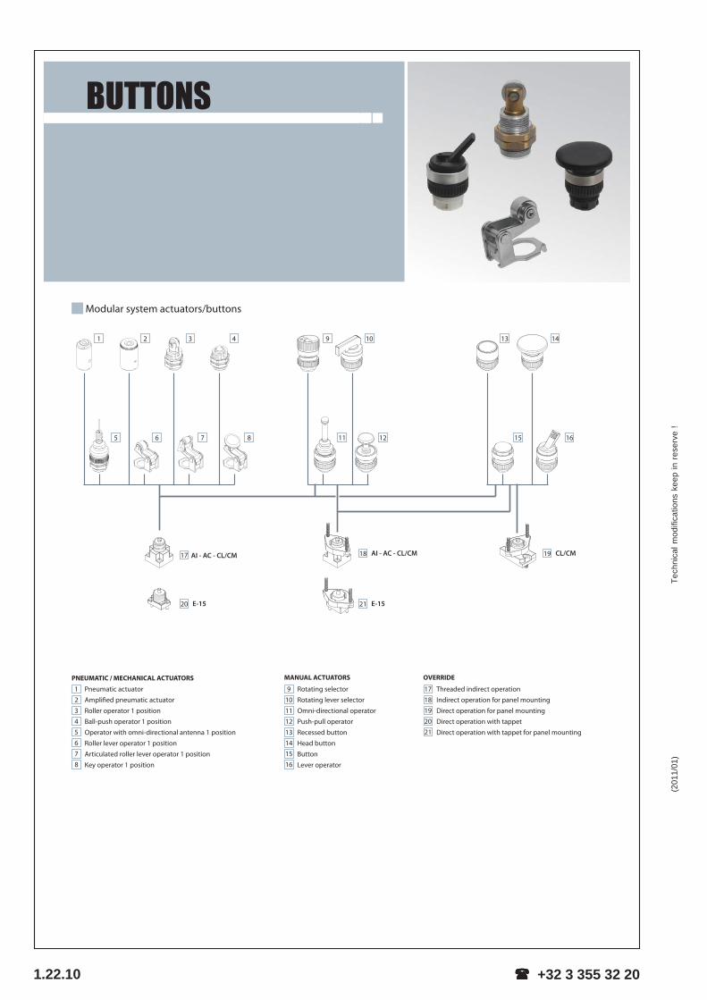
BUTTONS
19
Pneumatic actuator
Amplifi ed pneumatic actuator
Roller operator 1 position
Ball-push operator 1 position
Operator with omni-directional antenna 1 position
Roller lever operator 1 position
Articulated roller lever operator 1 position
Key operator 1 position
12345678
PNEUMATIC / MECHANICAL ACTUATORS
Rotating selector
Rotating lever selector
Omni-directional operator
Push-pull operator
Recessed button
Head button
Button
Lever operator
9101112
13141516
MANUAL ACTUATORS
Modular system actuators/buttons
Threaded indirect operation
Indirect operation for panel mounting
Direct operation for panel mounting
Direct operation with tappet
Direct operation with tappet for panel mounting
OVERRIDE
1718192021
E-1520
CL/CM18 AI - AC - CL/CM
21 E-15
17 AI - AC - CL/CM
1 2 3 4
5 6 7 8
9 10
11 12
13 14
15 16

Tech
nica
l mod
ifica
tions
kee
p in
res
erve
!(2
011/
07)
1.22.11
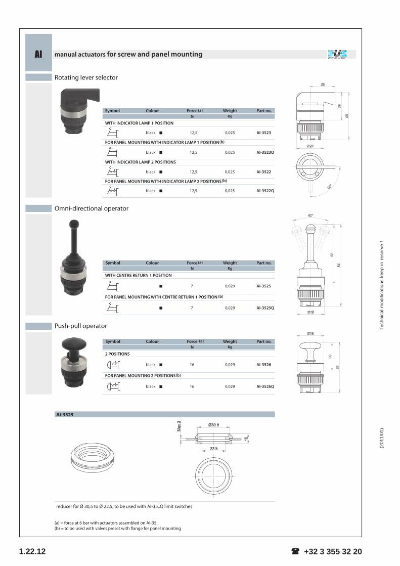
UNIVER GROUPmanual actuators for screw and panel mountingAI
FOR PANEL MOUNTINGS 2 POSITIONS
FOR PANEL MOUNTING 1 POSITION
(a) = force at 6 bar with actuators assembled on AI-35.. standard limit switch(b) = to be used with valves preset with fl ange for panel mounting
Recessed button
1 POSITION
0,0310,0310,031
AI-3511AI-3512AI-3513
0,0310,0310,031
AI-3511QAI-3512QAI-3513Q
FOR PANEL MOUNTING 1 POSITION
161616
161616
Part no.WeightKg
ColourSymbol ForceN
(a)
(b)
blackredgreen
blackredgreen
Head buttonPart Weight
KgColour
1 POSITION
0,0220,022
AI-3514AI-3516
0,0220,022
AI-3514QAI-3516Q
Symbol
2 POSITIONS
0,0220,022
AI-3514DAI-3516D
0,0220,022
AI-3514QDAI-3516QD
ForceN
1616
1616
1616
1616
(b)
FOR PANEL MOUNTING 2 POSITIONS (b)
redblack
redblack
redblack
redblack
ButtonPart no.Weight
KgColour
1 POSITION0,0250,0250,025
AI-3515AI-3517AI-3519
Symbol
0,0250,0250,025
AI-3515QAI-3517QAI-3519Q
ForceN
12,512,512,5
12,512,512,5
FOR PANEL MOUNTING 1 POSITION (b)
greenredblack
greenredblack
Accident prevention rotating selectorPart no.Weight
KgColour
WITH INDICATOR LAMP 1 POSITION
0,025 AI-3521
0,025 AI-3521Q
Symbol
WITH INDICATOR LAMP 2 POSITIONS
0,025 AI-3520
0,025 AI-3520Q
ForceN
12,5
12,5
12,5
12,5
FOR PANEL MOUNTING WITH INDICATOR LAMP 1 POSITION (b)
FOR PANEL MOUNTING WITH INDICATOR LAMP 2 POSITIONS (b)
black
black
black
black
Lever operator
Part no.WeightKg
ForceN
Colour
2 POSITIONS
6 0,022 AI-3524
6 0,022 AI-3524Q
Symbol
(b)
black
black
(a)
(a)
(a)
(a)
Ø22
Tech
nica
l mod
ifica
tions
kee
p in
res
erve
!(2
011/
01)
+32 3 355 32 201.22.12
UNIVER GROUPmanual actuators for screw and panel mountingAI
Ai
FOR PANEL MOUNTING 2 POSITIONS
Rotating lever selector
Part no.Colour
WITH INDICATOR LAMP 1 POSITION
AI-3523
AI-3523Q
Symbol
WITH INDICATOR LAMP 2 POSITIONS
AI-3522
ForceN
12,5
12,5
12,5
12,5
WeightKg
0,025
0,025
0,025
0,025 AI-3522Q
FOR PANEL MOUNTING WITH INDICATOR LAMP 1 POSITION(b)
FOR PANEL MOUNTING WITH INDICATOR LAMP 2 POSITIONS(b)
Omni-directional operator
FOR PANEL MOUNTING WITH CENTRE RETURN 1 POSITION
Part no.Colour
AI-3525Q
Symbol
WITH CENTRE RETURN 1 POSITION
ForceN
7
7
WeightKg
0,029
0,029 AI-3525
(a)
(b)
black
black
black
black
Push-pull operator
2 POSITIONS
AI-3526
AI-3526Q
Part no.
0,029
0,029
WeightKg
16
16
ForceN
ColourSymbol (a)
(b)
black
black
AI-3529
reducer for Ø 30,5 to Ø 22,5, to be used with AI-35..Q limit switches(for details refer to next page)
(a)
(a) = force at 6 bar with actuators assembled on AI-35..(b) = to be used with valves preset with fl ange for panel mounting
Tech
nica
l mod
ifica
tions
kee
p in
res
erve
!(2
011/
01)
1.22.13
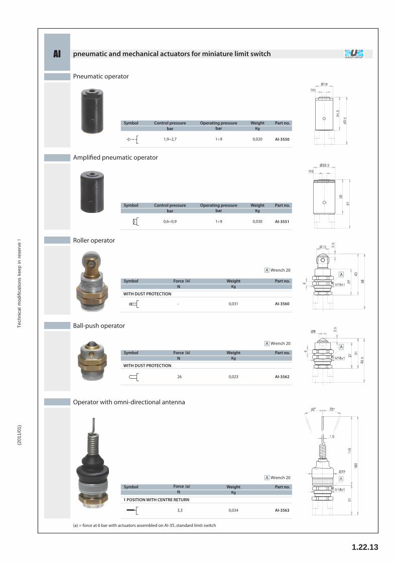
UNIVER GROUPpneumatic and mechanical actuators for miniature limit switchAI
WITH DUST PROTECTION
Amplifi ed pneumatic operator
Pneumatic operator
Part no.Symbol
AI-3550
Operating pressurebar
1÷9
WeightKg
0,020
Part no.Symbol
Control pressurebar
1,9÷2,7
Control pressurebar
0,6÷0,9 AI-3551
Operating pressurebar
1÷9
WeightKg
0,030
Operator with omni-directional antenna
Roller operator
Ball-push operator
A
(a) = force at 6 bar with actuators assembled on AI-35..standard limit switch
A
A
1 POSITION WITH CENTRE RETURN
WeightKg
0,034
Part no.Symbol
AI-35633,3
ForceN
(a)
Wrench 20A
Part no.Symbol ForceN
(a)
- AI-3560
WeightKg
0,031
Wrench 20A
WITH DUST PROTECTION
Part no.Symbol
AI-3562
ForceN
(a)
26
WeightKg
0,023
Wrench 20A

Tech
nica
l mod
ifica
tions
kee
p in
res
erve
!(2
011/
01)
+32 3 355 32 201.22.14
UNIVER GROUPpneumatic and mechanical actuators for miniature limit switchAI
A B
A B
Roller lever operator
Articulated roller operator
Symbol
1 POSITION
WeightKg
0,021
Part no.
AI-3571
ForceN
(a)
10
Key operator
Symbol
1 POSITION
(a)ForceN
10
WeightKg
0,021
Part no.
AI-3572
(a) = force at 6 bar with actuators assembled on AI-35..
Symbol
1 POSITION
WeightKg
0,021
Part no.
AI-3570
ForceN
(a)
10
Max openingA
B Total stroke
Max openingA
B Total stroke
Max openingA
B Total stroke
A B

Tech
nica
l mod
ifica
tions
kee
p in
res
erve
!(2
011/
01)
1.22.15
EMERGENCY & KEY SELECTOR VALVES series AZ
3/2 1/8" NC servo-piloted tappet with 90° actuator adaptor forpanel mounting - spring return
Order code:321MB90
5/2 1/8" servo-piloted tappet with 90° actuator adaptor forpanel mounting - spring return
Order code:521MB90
Actuators for panel mounting
Order code:RM065R
Emergency mushroom Ø40 RedOrder code:SSC/CD-V
Bi-stable key selector Black
Nominal orifice: 5 mmNominal flow rate at 6 bar: 550 Nl/minTemperature range: max +60°CWorking pressure: 2.5 ... 10 barActuating force: 4 NFluid: 50µ filtered, lubricated or non lubricated air
MaterialsBody: aluminium 11SSpool: nickel plated aluminiumSeals: NBRSprings: stainless steelInternal parts: brass OT 58