universal busnode cteu-dn
TRANSCRIPT

Description,functions andmaintenance
Bus nodes
Type CTEU-DN
DeviceNet fieldbusprotocol
Universal bus nodeCTEU-DN
Description573745en 1206NH[756445]


Contents and general safety instructions
I
Original de. . . . . . . . . . . . . . . . . . . . . . . . . . . . . . . . . . . . . . .
Edition en 1206NH. . . . . . . . . . . . . . . . . . . . . . . . . . . . . . . . .
Designation P.BE-CTEU-DN-OP+MAINT-EN. . . . . . . . . . . . . .
Order no. 573745. . . . . . . . . . . . . . . . . . . . . . . . . . . . . . . . . .
© (Festo SE & Co. KG, D-73726 Esslingen, 2012) Internet: http://www.festo.comE-Mail: [email protected]
Reproduction, distribution or sale of this document or communication of its contents to others without express authorization is prohibited. Offenders will be liable for damages. All rights reserved in the event that a patent, utility model or design patent is registered.
Festo P.BE-CTEU-DN-OP+MAINT-EN en 1206NH

Contents and general safety instructions
II Festo P.BE-CTEU-DN-OP+MAINT-EN en 1206NH
Allen-Bradley®, CAN®, DeviceNet®, CIP®, IO-Link®, QuickConnect®, Rockwell®, RockwellAutomation®, RSLinx®, RSLogix®, RSNetWorx® und TORX® are registered trademarks ofthe respective trademark owners in certain countries.

Contents and general safety instructions
IIIFesto P.BE-CTEU-DN-OP+MAINT-EN en 1206NH
Contents
Designated use VII. . . . . . . . . . . . . . . . . . . . . . . . . . . . . . . . . . . . . . . . . . . . . . . . . . . . . . . .
Range of application and certifications VIII. . . . . . . . . . . . . . . . . . . . . . . . . . . . . . . . . . . . .
Target group VIII. . . . . . . . . . . . . . . . . . . . . . . . . . . . . . . . . . . . . . . . . . . . . . . . . . . . . . . . . .
Service IX. . . . . . . . . . . . . . . . . . . . . . . . . . . . . . . . . . . . . . . . . . . . . . . . . . . . . . . . . . . . . . .
Instructions on this description IX. . . . . . . . . . . . . . . . . . . . . . . . . . . . . . . . . . . . . . . . . . .
Important user instructions X. . . . . . . . . . . . . . . . . . . . . . . . . . . . . . . . . . . . . . . . . . . . . .
1. Introduction 1-1. . . . . . . . . . . . . . . . . . . . . . . . . . . . . . . . . . . . . . . . . . . . . . . . . . .
1.1 General information on the CTEU product family 1-3. . . . . . . . . . . . . . . . . . . . . .
1.1.1 Hardware components 1-3. . . . . . . . . . . . . . . . . . . . . . . . . . . . . . . . . . .
1.1.2 I-port interface 1-4. . . . . . . . . . . . . . . . . . . . . . . . . . . . . . . . . . . . . . . . . .
1.1.3 CTEU-DN function range on the DeviceNet (brief overview) 1-5. . . . . .
1.2 General information on the fieldbus protocol DeviceNet 1-6. . . . . . . . . . . . . . . .
1.2.1 Central component of the fieldbus protocol 1-6. . . . . . . . . . . . . . . . . .
1.2.2 DeviceNet specifications 1-7. . . . . . . . . . . . . . . . . . . . . . . . . . . . . . . . . .
1.2.3 DeviceNet Conformance 1-7. . . . . . . . . . . . . . . . . . . . . . . . . . . . . . . . . .
2. Installation and interfaces 2-1. . . . . . . . . . . . . . . . . . . . . . . . . . . . . . . . . . . . . . .
2.1 Installation 2-3. . . . . . . . . . . . . . . . . . . . . . . . . . . . . . . . . . . . . . . . . . . . . . . . . . . .
2.1.1 Safety regulations 2-3. . . . . . . . . . . . . . . . . . . . . . . . . . . . . . . . . . . . . . .
2.1.2 Mounting the bus node 2-4. . . . . . . . . . . . . . . . . . . . . . . . . . . . . . . . . . .
2.2 Interfaces 2-6. . . . . . . . . . . . . . . . . . . . . . . . . . . . . . . . . . . . . . . . . . . . . . . . . . . . .
2.2.1 Connection and display components 2-6. . . . . . . . . . . . . . . . . . . . . . . .
2.2.2 Power supply 2-7. . . . . . . . . . . . . . . . . . . . . . . . . . . . . . . . . . . . . . . . . . .
2.2.3 Power supply connection 2-8. . . . . . . . . . . . . . . . . . . . . . . . . . . . . . . . .
2.2.4 Functional test - no network connection 2-8. . . . . . . . . . . . . . . . . . . . .
2.2.5 Fieldbus connection 2-9. . . . . . . . . . . . . . . . . . . . . . . . . . . . . . . . . . . . .
2.2.6 Basic settings for fieldbus communication 2-12. . . . . . . . . . . . . . . . . . .
Contents and general safety instructions
IV Festo P.BE-CTEU-DN-OP+MAINT-EN en 1206NH
2.3 Device replacement 2-17. . . . . . . . . . . . . . . . . . . . . . . . . . . . . . . . . . . . . . . . . . . . .
2.3.1 Replacing the bus node 2-17. . . . . . . . . . . . . . . . . . . . . . . . . . . . . . . . . .
2.3.2 Replacing the I-port device – identical device type 2-18. . . . . . . . . . . . .
2.3.3 Replacing the I-port device – different device type (change) 2-19. . . . .
2.3.4 Replacing the CAPC electrical connection box 2-20. . . . . . . . . . . . . . . . .
3. Preparing for commissioning 3-1. . . . . . . . . . . . . . . . . . . . . . . . . . . . . . . . . . . . .
3.1 Preparing to commissioning a PLC 3-3. . . . . . . . . . . . . . . . . . . . . . . . . . . . . . . . .
3.1.1 General instructions 3-3. . . . . . . . . . . . . . . . . . . . . . . . . . . . . . . . . . . . .
3.1.2 Prerequisites for commissioning 3-4. . . . . . . . . . . . . . . . . . . . . . . . . . .
3.2 Switching on 3-5. . . . . . . . . . . . . . . . . . . . . . . . . . . . . . . . . . . . . . . . . . . . . . . . . . .
3.2.1 Switching on the power supply 3-5. . . . . . . . . . . . . . . . . . . . . . . . . . . .
3.2.2 Normal operating status(fieldbus communication functional test) 3-6. . . . . . . . . . . . . . . . . . . .
3.2.3 DeviceNet participant features (EDS file) 3-10. . . . . . . . . . . . . . . . . . . . .
3.2.4 Downloading and installing an EDS file 3-11. . . . . . . . . . . . . . . . . . . . . .
3.2.5 Entering participant properties manually 3-12. . . . . . . . . . . . . . . . . . . .
4. Commissioning 4-1. . . . . . . . . . . . . . . . . . . . . . . . . . . . . . . . . . . . . . . . . . . . . . . .
4.1 Commissioning on the DeviceNet - Overview 4-3. . . . . . . . . . . . . . . . . . . . . . . . .
4.2 Network configuration and bus node parameterisation 4-5. . . . . . . . . . . . . . . .
4.2.1 Insert the participant in the project/network 4-5. . . . . . . . . . . . . . . . .
4.2.2 Assign the participant to a scanner 4-6. . . . . . . . . . . . . . . . . . . . . . . . .
4.2.3 Set the I/O parameters of the participant (Standard EDS) 4-7. . . . . . .
4.2.4 Assign the I/O addresses of the participant (Standard EDS) 4-9. . . . .
4.2.5 Loading the configuration into the scanner. 4-10. . . . . . . . . . . . . . . . . . .
4.3 Parameterisation 4-11. . . . . . . . . . . . . . . . . . . . . . . . . . . . . . . . . . . . . . . . . . . . . . .
4.3.1 Methods of parameterisation 4-11. . . . . . . . . . . . . . . . . . . . . . . . . . . . . .
4.3.2 Parameterisation with RSNetWorx (with standard EDS) 4-12. . . . . . . . .
4.3.3 Device-specific parametrisation 4-15. . . . . . . . . . . . . . . . . . . . . . . . . . . .
4.3.4 Behaviour of the inputs and outputs in fail state mode 4-15. . . . . . . . .
4.3.5 Behaviour of the inputs and outputs in idle state mode 4-16. . . . . . . . .
4.3.6 Parameterisation via a user program (explicit messaging) 4-16. . . . . . .
4.4 Checklist for commissioning 4-19. . . . . . . . . . . . . . . . . . . . . . . . . . . . . . . . . . . . . .

Contents and general safety instructions
VFesto P.BE-CTEU-DN-OP+MAINT-EN en 1206NH
5. Diagnostics 5-1. . . . . . . . . . . . . . . . . . . . . . . . . . . . . . . . . . . . . . . . . . . . . . . . . . .
5.1 Summary of diagnostics options 5-3. . . . . . . . . . . . . . . . . . . . . . . . . . . . . . . . . . .
5.2 Diagnostics via LED display 5-4. . . . . . . . . . . . . . . . . . . . . . . . . . . . . . . . . . . . . . .
5.2.1 Normal operating status display 5-4. . . . . . . . . . . . . . . . . . . . . . . . . . .
5.2.2 PS-LED status display 5-5. . . . . . . . . . . . . . . . . . . . . . . . . . . . . . . . . . . .
5.2.3 Status display X1-/X2-LEDs 5-6. . . . . . . . . . . . . . . . . . . . . . . . . . . . . . .
5.2.4 Status display MNS-LED 5-8. . . . . . . . . . . . . . . . . . . . . . . . . . . . . . . . . .
5.2.5 I/O-LED status display 5-9. . . . . . . . . . . . . . . . . . . . . . . . . . . . . . . . . . . .
5.3 Reaction to malfunctions in the control system 5-10. . . . . . . . . . . . . . . . . . . . . . .
5.4 Diagnostics via network/fieldbus 5-11. . . . . . . . . . . . . . . . . . . . . . . . . . . . . . . . . .
5.4.1 Diagnostics via configuration software 5-11. . . . . . . . . . . . . . . . . . . . . .
5.4.2 Short circuit/overload 5-13. . . . . . . . . . . . . . . . . . . . . . . . . . . . . . . . . . . .
6. Error handling 6-1. . . . . . . . . . . . . . . . . . . . . . . . . . . . . . . . . . . . . . . . . . . . . . . . .
6.1 Fault finding and error elimination 6-3. . . . . . . . . . . . . . . . . . . . . . . . . . . . . . . . .
6.1.1 Check installation 6-3. . . . . . . . . . . . . . . . . . . . . . . . . . . . . . . . . . . . . . .
6.1.2 Check the power supply 6-4. . . . . . . . . . . . . . . . . . . . . . . . . . . . . . . . . .
6.1.3 Restart communication between the bus node and the device 6-5. . .
6.1.4 Check fieldbus communication 6-5. . . . . . . . . . . . . . . . . . . . . . . . . . . . .
6.1.5 Check DeviceNet configuration 6-6. . . . . . . . . . . . . . . . . . . . . . . . . . . . .
6.1.6 Read out diagnostic messages via DeviceNet 6-7. . . . . . . . . . . . . . . . .

Contents and general safety instructions
VI Festo P.BE-CTEU-DN-OP+MAINT-EN en 1206NH
A. Technical appendix A-1. . . . . . . . . . . . . . . . . . . . . . . . . . . . . . . . . . . . . . . . . . . . .
A.1 Technical data A-3. . . . . . . . . . . . . . . . . . . . . . . . . . . . . . . . . . . . . . . . . . . . . . . . . .
A.1.1 General properties A-3. . . . . . . . . . . . . . . . . . . . . . . . . . . . . . . . . . . . . .
A.1.2 Power supply A-6. . . . . . . . . . . . . . . . . . . . . . . . . . . . . . . . . . . . . . . . . . .
A.1.3 Signal transmission A-7. . . . . . . . . . . . . . . . . . . . . . . . . . . . . . . . . . . . . .
A.2 Terms and abbreviations A-8. . . . . . . . . . . . . . . . . . . . . . . . . . . . . . . . . . . . . . . . .
A.3 Fail state behaviour A-11. . . . . . . . . . . . . . . . . . . . . . . . . . . . . . . . . . . . . . . . . . . . .
A.4 DeviceNet object model A-13. . . . . . . . . . . . . . . . . . . . . . . . . . . . . . . . . . . . . . . . . .
A.4.1 DeviceNet Object model for CTEU-DN – overview A-13. . . . . . . . . . . . . .
A.4.2 Participant features (Identity object) A-16. . . . . . . . . . . . . . . . . . . . . . . .
A.4.3 DeviceNet object A-17. . . . . . . . . . . . . . . . . . . . . . . . . . . . . . . . . . . . . . . .
A.4.4 Assembly Object A-18. . . . . . . . . . . . . . . . . . . . . . . . . . . . . . . . . . . . . . . .
A.4.5 Discrete output byte object A-19. . . . . . . . . . . . . . . . . . . . . . . . . . . . . . .
A.4.6 Discrete input byte object A-20. . . . . . . . . . . . . . . . . . . . . . . . . . . . . . . . .
A.4.7 Festo diagnostic object (I-port status byte) A-21. . . . . . . . . . . . . . . . . . .
A.4.8 Festo module object A-23. . . . . . . . . . . . . . . . . . . . . . . . . . . . . . . . . . . . .
A.4.9 Festo system object A-24. . . . . . . . . . . . . . . . . . . . . . . . . . . . . . . . . . . . . .
A.4.10 Festo parameter object A-25. . . . . . . . . . . . . . . . . . . . . . . . . . . . . . . . . . .
B. Index B-1. . . . . . . . . . . . . . . . . . . . . . . . . . . . . . . . . . . . . . . . . . . . . . . . . . . . . . . . .

Contents and general safety instructions
VIIFesto P.BE-CTEU-DN-OP+MAINT-EN en 1206NH
Designated use
The bus node type CTEU-DN documented in this descriptionmanual has been designed exclusively for use as a parti-cipant (slave-device) on the DeviceNet fieldbus.
The bus node may only be used as follows:
– As intended in industrial environments;outside of industrial environments, e.g. in commercial andmixed-residential areas, actions to suppress interferencemay have to be taken.
– in original status without unauthorised modifications;only the conversions or modifications described in thedocumentation supplied with the product are permitted.
– in perfect technical condition
The limit values specified for pressures, temperatures, elec-trical data, torques etc. must be observed.
Comply with the legal rules and regulations and standards,rules of the testing organisations and insurance companiesand national specifications applicable for the location.
Warning• Use only PELV circuits for the electrical power supply inaccordance with IEC/EN 60204-1(Protective Extra-Low Voltage, PELV).
• Observe also the general requirements for PELV circuitsin accordance with IEC/EN 60204-1.
• Use only voltage sources that ensure a reliable electricseparation of operating voltage in accordance withIEC/EN 60204-1.
• Always connect both circuits for operating and loadvoltage supply.

Contents and general safety instructions
VIII Festo P.BE-CTEU-DN-OP+MAINT-EN en 1206NH
Through the use of PELV circuits, protection against electricshock (protection against direct and indirect contact) is en-sured in accordance with IEC/EN 60204-1.
Range of application and certifications
The product fulfils the requirements of EU directives and ismarked with the CE marking.
Standards and test values which the product must complywith and fulfil can be found in the section “Technical ap-pendix”. The product-relevant EU directives can be found inthe declaration of conformity.
Certificates and declarations of conformity for this productcan be found online at:
www.festo.com
Information on DeviceNet can be found online at:
www.odva.org
The bus node has been certified by the Open Device VendorAssociation (ODVA):
Target group
This description is intended exclusively for technicianstrained in control and automation technology, who haveexperience in installation, commissioning, programming anddiagnostics of programmable logic controllers (PLC) andfieldbus systems.

Contents and general safety instructions
IXFesto P.BE-CTEU-DN-OP+MAINT-EN en 1206NH
Service
Please contact your local Festo service centre if you have anytechnical problems.
Instructions on this description
This manual is Part II of the product documentation andcontains specific information about the configuration,parameterisation, commissioning, programming anddiagnostics of the bus node with the DeviceNet fieldbusprotocol.
Information relating to installing the bus node can be found inPart I of the product documentation entitled “Universal busnode CTEU-DN - Installation and Interfaces”, which is sup-plied with the bus node.
All information on installation and the interfaces can also befound in Section 2.1 of this description.
Information for mounting the bus node on the CAPC electricalconnection box can be found in the assembly instructionssupplied with the electrical connection box.
Information about other bus nodes and components of theCTEU… product family can be found in the user documenta-tion for the respective product.
All documents can also be found online at:
www.festo.com Support Portal: Enter search term,e.g. “CTEU” User documentation

Contents and general safety instructions
X Festo P.BE-CTEU-DN-OP+MAINT-EN en 1206NH
Important user instructions
Danger categories
This description includes instructions on the possible dangerswhich can occur if the product is used incorrectly. Theseinstructions are marked with a signal word (Warning, Caution,etc.), printed on a shaded background and markedadditionally with a pictogram.
A distinction is made between the following danger warnings:
Warning... means that failure to observe this instruction may resultin serious personal injury or material damage.
Caution... means that failure to observe this instruction may resultin personal injury or material damage.
Note... means that failure to observe this instruction may resultin material damage.
In addition, the following pictogram marks passages in thetext which describe activities with electrostatically sensitivedevices:
Electrostatically sensitive devices: Incorrect handling maycause damage to devices.

Contents and general safety instructions
XIFesto P.BE-CTEU-DN-OP+MAINT-EN en 1206NH
Marking special information
The following pictograms mark passages in the text whichcontain special information.
Pictograms
Information:Recommendations, tips and references to other informationsources.
Accessories:Specifications on necessary or useful accessories for theFesto product.
Environment:Information on the environmentally friendly use of Festoproducts.
Text designations
• Bullet points denote activities that may be carried out inany sequence.
1. Numerals denote activities that must be carried out in thesequence specified.
– Arrowheads indicate general lists.

Contents and general safety instructions
XII Festo P.BE-CTEU-DN-OP+MAINT-EN en 1206NH
The table below contains all the essential product and net-work-specific terms and abbreviations that are used in thisdescription.
An overview of all terms and abbreviations can be found in the Appendix A.2.
Abbreviation/term Significance
EDS Electronic Data Sheets contain product-specific data, e.g. the bus nodecharacteristics see also “DCF” Appendix A.2
EDS library Manages the characteristics of the various fieldbus/network participants
Fail state Bus node function, also referred to as “fail safe” function; defines thestate assumed by outputs or valves following network or communicationerrors, activates for example a reset of the outputs - or alternatively holdsthe last state
I-port I-port is a Festo-specific interface for transmitting communication data(process data, sensor signals, pilot signals) and supply voltages. TheI-port communication protocol is based on the IO link protocol. The elec-trical and mechanical link between bus nodes and I-port device is stand-ardised.
Object Directory Makes all important fieldbus/network participant parameters accessiblein a standardised manner
ODVA Open Device Vendor Association, DeviceNet umbrella organisation
PLC Programmable logic controller, also referred to as system controller orcontroller for short
RSNetWorx Configuration, parameterisation, commissioning and diagnostics softwarefor DeviceNet from Rockwell Automation/Allen-Bradley
Tab. 0/1: System-specific terms and abbreviations (extract)
Introduction
1-1Festo P.BE-CTEU-DN-OP+MAINT-EN en 1206NH
Chapter 1
Introduction

1. Introduction
1-2 Festo P.BE-CTEU-DN-OP+MAINT-EN en 1206NH
Contents
1. Introduction 1-1. . . . . . . . . . . . . . . . . . . . . . . . . . . . . . . . . . . . . . . . . . . . . . . . . . .
1.1 General information on the CTEU product family 1-3. . . . . . . . . . . . . . . . . . . . . .
1.1.1 Hardware components 1-3. . . . . . . . . . . . . . . . . . . . . . . . . . . . . . . . . . .
1.1.2 I-port interface 1-4. . . . . . . . . . . . . . . . . . . . . . . . . . . . . . . . . . . . . . . . . .
1.1.3 CTEU-DN function range on the DeviceNet (brief overview) 1-5. . . . . .
1.2 General information on the fieldbus protocol DeviceNet 1-6. . . . . . . . . . . . . . . .
1.2.1 Central component of the fieldbus protocol 1-6. . . . . . . . . . . . . . . . . .
1.2.2 DeviceNet specifications 1-7. . . . . . . . . . . . . . . . . . . . . . . . . . . . . . . . . .
1.2.3 DeviceNet Conformance 1-7. . . . . . . . . . . . . . . . . . . . . . . . . . . . . . . . . .

1. Introduction
1-3Festo P.BE-CTEU-DN-OP+MAINT-EN en 1206NH
1.1 General information on the CTEU product family
The CTEU… product family enables the creation of a decent-ralised automation system in a DeviceNet fieldbus system(network).
1.1.1 Hardware components
1 Higher-order con-troller (Host sys-tem/Master/PLC/IPC)
2 Fieldbus level:bus nodeCTEU-DN
3 Device level:e.g. valveterminal VTUB-12
4 Drive level:e.g. Linearmodule HME
1
2
3
4

1. Introduction
1-4 Festo P.BE-CTEU-DN-OP+MAINT-EN en 1206NH
1.1.2 I-port interface
I-port is a Festo-specific interface for transmitting communic-ation data (process data, sensor signals, pilot signals) andsupply voltages.
The I-port communication protocol is based on the IO linkprotocol. The electrical and mechanical link between busnodes and I-port device is standardised.
The bus node has separate operating and load voltage sup-plies. It also supplies voltage to the devices connected via theI-port interface.
Located at the bottom of the bus node is the I-port interfacefor connection to an I-port-compatible device, e.g. valve ter-minal or decentralised electrical connection box.
1. Introduction
1-5Festo P.BE-CTEU-DN-OP+MAINT-EN en 1206NH
1.1.3 CTEU-DN function range on the DeviceNet (brief overview)
– Object-based fieldbus system
– Master-Slave system architecture
– Process synchronisation in accordance with the Producer/Consumer method
– Connection-based communication procedure: point-to-point connection (peer-to-peer messaging), where applic-able as Multicast connection and/or Master/slave I/Oconnection
– Predefined master/slave connection set for the simplifiedtransmission of I/O data between the master and the PLCand the slave and the bus node
– Real-time operation: Exchange of I/O data in “real-time”
– Message types supported for the Master/slave I/O con-nection:
– Polled communication (“I/O polling”)
– Change of state / Cyclic communication
– Supports the QuickConnect feature and the AutomaticDevice Replacement (ADR) function: guarantees fasterreconnection between DeviceNet-Scanner and bus nodes,e.g. after replacing the bus nodes
– Application-specific process data transmission based onthe Common Industrial Protocol (CIP):
– Time-critical I/O data via “I/O messages”(I/O messaging or implicit messaging)
– Data required for configuration, diagnostics andmanagement via explicit messaging
– Module-specific parameterisation via manufacturer-spe-cific objects

1. Introduction
1-6 Festo P.BE-CTEU-DN-OP+MAINT-EN en 1206NH
1.2 General information on the fieldbus protocol DeviceNet
1.2.1 Central component of the fieldbus protocol
Participant features
A DeviceNet participant is configured based on product-spe-cific data and characteristics, which the manufacturerprovides in the form of electronic datasheets (EDS). TheseEDS files contain the product code, revision data and theavailable address space (input/output size).
The configuration program of the DeviceNet Master managesthe EDS files of all fieldbus participants in a list or an EDSlibrary.
Special Device Configuration Files contain additional projectdata over and above the content and scope of the EDS file.
Communication protocol
According to the layer model of the International Organisationfor Standardisation (Open Systems Interconnection ReferenceModel - OSI), DeviceNet uses the principles of the ControllerArea Network (CAN) Protocol at security layer level (Data LinkLayer), as well as the Common Industrial Protocol (CIP) for theupper communication level.
The DeviceNet protocol therefore represents a conversionfrom CIP based on CAN principles.

1. Introduction
1-7Festo P.BE-CTEU-DN-OP+MAINT-EN en 1206NH
Message types
The following message types are available for master/slavenetworks (predefined master/slave connection set):
– Polled communication (“I/O polling”)
or
– Change of state / Cyclic communication
Object directories
DeviceNet devices have an object directory which makes allimportant participant parameters accessible in a standard-ized manner. A DeviceNet system is essentially configured byaccessing the objects in the object directory of the individualfieldbus participants.
1.2.2 DeviceNet specifications
Further Information on DeviceNet can be found in theInternet:
DeviceNet specifications
ODVA Open Device Vendor Association http://www.odva.org
Tab. 1/1: DeviceNet specifications
1.2.3 DeviceNet Conformance
The CTEU-DN bus node conforms to the specifications of theOpen Device Vendor Association (ODVA).

1. Introduction
1-8 Festo P.BE-CTEU-DN-OP+MAINT-EN en 1206NH

Installation and interfaces
2-1Festo P.BE-CTEU-DN-OP+MAINT-EN en 1206NH
Chapter 2
Installation and interfaces

2. Installation and interfaces
2-2 Festo P.BE-CTEU-DN-OP+MAINT-EN en 1206NH
Contents
2. Installation and interfaces 2-1. . . . . . . . . . . . . . . . . . . . . . . . . . . . . . . . . . . . . . .
2.1 Installation 2-3. . . . . . . . . . . . . . . . . . . . . . . . . . . . . . . . . . . . . . . . . . . . . . . . . . . .
2.1.1 Safety regulations 2-3. . . . . . . . . . . . . . . . . . . . . . . . . . . . . . . . . . . . . . .
2.1.2 Mounting the bus node 2-4. . . . . . . . . . . . . . . . . . . . . . . . . . . . . . . . . . .
2.2 Interfaces 2-6. . . . . . . . . . . . . . . . . . . . . . . . . . . . . . . . . . . . . . . . . . . . . . . . . . . . .
2.2.1 Connection and display components 2-6. . . . . . . . . . . . . . . . . . . . . . . .
2.2.2 Power supply 2-7. . . . . . . . . . . . . . . . . . . . . . . . . . . . . . . . . . . . . . . . . . .
2.2.3 Power supply connection 2-8. . . . . . . . . . . . . . . . . . . . . . . . . . . . . . . . .
2.2.4 Functional test - no network connection 2-8. . . . . . . . . . . . . . . . . . . . .
2.2.5 Fieldbus connection 2-9. . . . . . . . . . . . . . . . . . . . . . . . . . . . . . . . . . . . .
2.2.6 Basic settings for fieldbus communication 2-12. . . . . . . . . . . . . . . . . . .
2.3 Device replacement 2-17. . . . . . . . . . . . . . . . . . . . . . . . . . . . . . . . . . . . . . . . . . . . .
2.3.1 Replacing the bus node 2-17. . . . . . . . . . . . . . . . . . . . . . . . . . . . . . . . . .
2.3.2 Replacing the I-port device – identical device type 2-18. . . . . . . . . . . . .
2.3.3 Replacing the I-port device – different device type (change) 2-19. . . . .
2.3.4 Replacing the CAPC electrical connection box 2-20. . . . . . . . . . . . . . . . .

2. Installation and interfaces
2-3Festo P.BE-CTEU-DN-OP+MAINT-EN en 1206NH
2.1 Installation
This chapter contains information for mounting the Bus nodeCTEU on an I-port-compatible device (e.g. valve terminal withI-port interface) and for installing this combination in a high-er-level field bus system (network).
2.1.1 Safety regulations
WarningDanger of injury through uncontrolled movements of con-nected equipment.
Make sure that electrical and pneumatic equipment are ina de-energised and pressureless status.
Before working on the pneumatics:
• Switch off the compressed air supply
• Vent the valve terminal
Before working on the electrical components, e.g. beforeinstallation or maintenance work:
• Switch off power supply
In this way, you can avoid:
– uncontrolled movements of loose tubing
– accidental and uncontrolled movements of the connec-ted actuators
– undefined switching states of the electronics

2. Installation and interfaces
2-4 Festo P.BE-CTEU-DN-OP+MAINT-EN en 1206NH
NoteThe bus node includes electrostatically sensitive devices.
• Do not touch any electrical or electronic components.
• Observe the handling specifications for electrostaticallysensitive devices.
They will help you avoid damage to the electronics.
NoteUse protective caps to seal unused connections. This ishow you achieve protection class IP65/IP67.
2.1.2 Mounting the bus node
A valve terminal with I-port interface or an electrical connec-tion box, type CAPC-..., is required to mount the bus node.
NoteInformation on mounting the bus node on the electricalconnection box type CAPC-... can be found in the assemblyinstructions that accompany the connection box.For H-rail mounting, you also need the mounting kitCAFM-... (CAPC and CAFM).
1. Inspect the seals and sealing surfaces on bus node andvalve terminal.

2. Installation and interfaces
2-5Festo P.BE-CTEU-DN-OP+MAINT-EN en 1206NH
2. Plug the bus node onto the valve terminal in the rightposition and without tilting.
3. First, lightly screw in the three self-tapping screws with aTORX screwdriver (size T10): use existing threads, if ap-plicable.
4. Tighten the screws with 1.0 Nm.

2. Installation and interfaces
2-6 Festo P.BE-CTEU-DN-OP+MAINT-EN en 1206NH
2.2 Interfaces
2.2.1 Connection and display components
The following electrical connection and display componentscan be found on the bus node:
1 2 3
45
X0
1 DIL switch group 1 ( Section 2.2.6)
2 DIL switch group 2 ( Section 2.2.6)
3 Status LEDs:bus status LEDs, CTEU-specific LEDs;status indicator and diagnostics ( Section 3.2.2)
4 Power supply connectionfor bus node and any connected equipment,e.g. valve terminal ( Section 2.2.2);M12, 5-pin, B-coded, pin plug connector
5 Field bus connection (field bus interface):sub-D, 9-pin, pin plug connector, DE-9( Section 2.2.3)
On the bottom of the bus node is the I-port interface for con-nection to an I-port-compatible device, e.g. valve terminal ordecentralised electrical connection box.

2. Installation and interfaces
2-7Festo P.BE-CTEU-DN-OP+MAINT-EN en 1206NH
2.2.2 Power supply
The bus node has separate operating and load voltagesupplies. The bus node also supplies voltage to equipmentconnected via the I-port interface.
Note• Use only PELV circuits for the electrical power supply inaccordance with IEC/EN 60204-1(Protective Extra-Low Voltage, PELV).
• Observe the general requirements in accordance withIEC/EN 60204-1 for PELV circuits.
• Use only voltage sources that guarantee a reliable elec-tric separation of operating and load voltage in accord-ance with IEC/EN 60204-1.
• Always connect both circuits for operating and loadvoltage supply.
Through the use of PELV circuits, protection against electricshock (protection against direct and indirect contact) is en-sured in accordance with IEC/EN 60204-1.
NoteFieldbus participants of different manufacturers have dif-ferent tolerances regarding the power supply to the bus(V+, also designated as CAN_V+ or CAN+).
– Tolerance range of the power supply to the bus of thefieldbus interface CTEUDN: DC 11 … 30 V, reverse polar-ity protected
Observe this fact when placing the power supply unit anddesigning the fieldbus length.

2. Installation and interfaces
2-8 Festo P.BE-CTEU-DN-OP+MAINT-EN en 1206NH
2.2.3 Power supply connection
Power supply connec-tion (M12, B-coded)
Pin Assignment 1)
1
5
2
4
3
1 24 VEL/SEN (PS)
2 24 VVAL/OUT (PL)
3 0 VEL/SEN (PS)
4 0 VOUT/VAL (PL)
5 FU 2)
1) VEL/SEN: Operating voltage for electronics/sensors(Power System, PS)
VOUT/VAL: Load voltage for outputs/valves(Power Load, PL)
FE: Earth terminal (functional earth)2) The connection to functional earth must be ensured via the
connected device or electrical connection box CAPC-...
Tab. 2/2: Power supply connection
For the connection to power supply units or the power supply,use cables with M12 coupling (socket plug connector),B-coded, in accordance with IEC 61076-2 Accessories www.festo.com/catalogue.
2.2.4 Functional test - no network connection
Check the operating status of the bus node using the statusLEDs PS and X1 and/or X2:
– The LED PS is illuminated green when the power supply ispresent at both circuits.
– The LEDs X1 and/or X2 illuminate green when an I-portdevice is connected.
2. Installation and interfaces
2-9Festo P.BE-CTEU-DN-OP+MAINT-EN en 1206NH
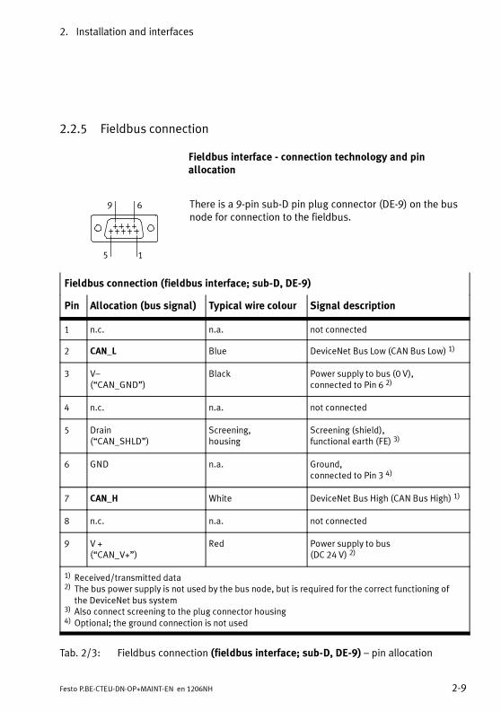
2.2.5 Fieldbus connection
Fieldbus interface - connection technology and pinallocation
9 6
5 1
There is a 9-pin sub-D pin plug connector (DE-9) on the busnode for connection to the fieldbus.
Fieldbus connection (fieldbus interface; sub-D, DE-9)
Pin Allocation (bus signal) Typical wire colour Signal description
1 n.c. n.a. not connected
2 CAN_L Blue DeviceNet Bus Low (CAN Bus Low) 1)
3 V–(“CAN_GND”)
Black Power supply to bus (0 V),connected to Pin 6 2)
4 n.c. n.a. not connected
5 Drain(“CAN_SHLD”)
Screening,housing
Screening (shield),functional earth (FE) 3)
6 GND n.a. Ground,connected to Pin 3 4)
7 CAN_H White DeviceNet Bus High (CAN Bus High) 1)
8 n.c. n.a. not connected
9 V +(“CAN_V+”)
Red Power supply to bus(DC 24 V) 2)
1) Received/transmitted data2) The bus power supply is not used by the bus node, but is required for the correct functioning of
the DeviceNet bus system3) Also connect screening to the plug connector housing4) Optional; the ground connection is not used
Tab. 2/3: Fieldbus connection (fieldbus interface; sub-D, DE-9) – pin allocation

2. Installation and interfaces
2-10 Festo P.BE-CTEU-DN-OP+MAINT-EN en 1206NH
Fieldbus connecting cable – Specification and configuration
For fieldbus communication, Festo recommends the use of atwo-pair, screened fieldbus connecting cable (network cable).
• You need at least a screened 4-wire line(CAN_H/CAN_L as well as V +/V –).
• Preferably use cable with twisted and screened wirepairs.
• Always use a terminating resistor (121Ω ±1%, 0.25W)at both ends of the fieldbus between the wires forCAN_H and CAN_L.
• Connect the screening of the fieldbus cable to thefieldbus plug.
• Connect the screening continuously to all fieldbuscables and earth the screening only once (star-shaped) to avoid ground loops.
• Make sure that the connected fieldbus equipment orthe decentralised adapter is earthed.
• Observe the specifications in the manuals of your con-trol system, in particular regarding the bus lines,cable type, max. length of branch lines and branchesas well as the connection technology (network plug,adapter).
• In calculating the max. effective data rate, also takeinto account the length of branch lines and branches Section 2.2.6, “Setting the DIL switches” Information on maximum usable data rate (baudrate).

2. Installation and interfaces
2-11Festo P.BE-CTEU-DN-OP+MAINT-EN en 1206NH
NoteFaulty installation and high transmission rates may causedata transmission errors as a result of signal reflectionsand attenuations.
Fieldbus adapter (bus connection/plug-adapter) forcontinued fieldbus communication
With fieldbus adapters from Festo ( Tab. 2/4 below), youcan separate the fieldbus connection from the bus nodewithout interrupting the communication of the remainingfieldbus participants.
You can use the following fieldbus adapters for forwardingthe fieldbus connection.
Fieldbus adapter Pin Allocation
Bus connectionFBA-2-M12-5POL 1)
1 Functional earth (FE)
5
2
3
4
15
1
4
3
2
Bus IN Bus OUT
1)
2 Power supply to bus (DC 24 V)
3 Power supply to bus (0 V)
4 CAN_H
5 CAN_L
Tab. 2/4: Fieldbus adapter (bus connection/plug-adapter) - Part 1

2. Installation and interfaces
2-12 Festo P.BE-CTEU-DN-OP+MAINT-EN en 1206NH
Fieldbus adapter Pin Allocation
Bus connectionFBA-1-SL-5POLwith FBSD-KL-2X5POL 2)
1 Power supply to bus (0 V)
1 2 3 4 5
2 CAN_L
3 Functional earth (FE)
4 CAN_H
5 Power supply to bus (DC 24 V)
Fieldbus adapterFBA-CO-SUB-9-M12 3)
Assembly instructionsFBA-CO-SUB-9-M12
Fieldbus adapterFBS-SUB-9-BU-2x5PIN-B
Assembly instructionsFBS-SUB-9-BU-2x5PIN-B
Fieldbus adapterFBS-SUB-9-WS-CO-K
www.festo.com Support Portal
1) Protective cap or plug with bus termination resistor required if connection remains unused2) Use cables with a minimum cross-section of 0.34 mm2
3) When using standard sub-D plugs to IP20: Connecting screws with UNC female thread required formounting (type UNC 4-40/M3x6)
Tab. 2/5: Fieldbus adapter (bus connection/plug-adapter) - Part 2
2.2.6 Basic settings for fieldbus communication
The following basic settings for fieldbus communication mustbe made using the DIL switches on the bus node ( Sectionsbelow):
– DeviceNet address (“Station number”)
– Data rate (baud rate)

2. Installation and interfaces
2-13Festo P.BE-CTEU-DN-OP+MAINT-EN en 1206NH
– Diagnostic functionality (transmission of diagnostic in-formation to the process data or access to diagnostic in-formation exclusively via Explicit Messaging)
– Fail state and idle state mode
To set the DIL switches, you must remove the cover:
Removal of the DIL switch cover
Proceed as follows:
1. Switch off the power supply.
2. Unscrew the two mounting screws of the transparentcover and remove the cover.
Setting the DIL switches
Proceed as follows:
1. Assign to the bus node a station that has not yet beenallocated see examples below for setting the binary-coded DeviceNet address (“Station Numbers”) per DILswitch group 1 Tab. 2/6.
Example 1:Station number 05
Example 2:Station number 38
1 2 3 4 5 6 1 1 2 3 4 5 6 1
Tab. 2/6: Setting example for DeviceNet address (“Station number”, DIL switchgroup 1)

2. Installation and interfaces
2-14 Festo P.BE-CTEU-DN-OP+MAINT-EN en 1206NH
DIL switch 1) Function
1 2 3 4 5 6 1 2 3 4 5 6
1 2 3 4 5
DIL switch group 1
1 1 ... 6: DeviceNet address (Station Number), 0 … 63, binary-coded (factory setting: 63)
DIL switch group 2
2 1 ... 2: reserved (OFF)
3 3 ... 4: Data rate/baud rate 2)
250 kB
2.3 2.4
125 kB
2.3 2.4
DIL 2.3: OFFDIL 2.4: OFF
DIL 2.3: ONDIL 2.4: OFF
Reserved
2.3 2.4
500 kB
2.3 2.4
DIL 2.3: OFFDIL 2.4: ON
DIL 2.3: ONDIL 2.4: ON
4 5: Diagnostics mode ON: Diagnostics activated:Transmission of diagnostic in-formation to the process data
OFF: Access to diagnostic in-formation only through explicitmessaging (factory setting)
5 6: Fail-state andidle mode 3)
ON: Hold last state OFF: Reset(factory setting)
1) Switch setting “ON”: (marked on DIL switch accordingly, shown in Fig. at top)Switch setting “OFF”: (shown in Fig. at bottom)
2) Factory setting: 125 kBaud3) The setting for the fail state mode and the idle mode apply for all inputs and outputs
– Fail state: no fieldbus connection (connection aborted)– Idle state: PLC is in stop mode Note Fail state mode is also referred to as “Fail safe mode”
Tab. 2/7: Setting the DIL switch (DIL switch group 1 and 2)

2. Installation and interfaces
2-15Festo P.BE-CTEU-DN-OP+MAINT-EN en 1206NH
2. Set the baud rate: when setting the baud rate, take intoaccount the length of the network lines (main bus line,branch lines and branches) see note below.
NoteMaximum effective data rate (baud rate)The setting of the baud rate depends on the length of allfieldbus connecting cables (network lines).
• Consider the length of the fieldbus line between the PLCand bus node (main bus line) as well as the length of anyexisting branch lines and branches for continued field-bus configuration.
• Also consider the overall length (sum) of all branch lines.
• The table below contains reference values for the max-imum baud rate, depending on the line lengths. Thebaud rates named here are not supported by all control-lers.
• Observe any deviating specifications in the manual ofyour control system or network scanner.
• Further information can be found in the specifications ofthe ODVA www.odva.org.
Max. data rate (baud rate)dependent on the line length (reference values)
Main busline(Trunk line)
Branch line(Drop line)
Baud rate
Individual branch line All branch lines (total)
Max. 100 m Max. 6 m Max. 39 m 500 kBaud
Max. 250 m Max. 6 m Max. 78 m 250 kBaud
Max. 500 m Max. 6 m Max. 156 m 125 kBaud
Tab. 2/8: Maximum data rate (baud rate)

2. Installation and interfaces
2-16 Festo P.BE-CTEU-DN-OP+MAINT-EN en 1206NH
3. Set the diagnostics and fail-state mode.
Mounting of the DIL switch cover
1. Place the cover carefully on the bus node. Make sure thatthe seal is seated correctly.
2. Tighten the two mounting screws at first hand-tight andthen with a max. torque of 0.4 Nm.
Functional test after making the DIL switch setting -with network connection
Check the operating status of the bus node:
1. Connect the bus node to the fieldbus.
2. Check the network connection to the PLC using the statusLEDsMNS and IO Tab. 2/9 below(additional information can be found in Section 3.2.2).
FunctioncheckWith networkconnection
Bus node andnetwork connectionnot configured
Bus node andnetwork connectionconfigured
StatusOperatingstatus of busnode (testresult)
PLCin Stopmode
PLCin Runmode
LEDMNS Flashes green Illuminates green Illuminates green OK
LED IO Is off Flashes green Illuminates green OK
Tab. 2/9: Functional test using the status LEDs MNS and IO - after making the DILswitch setting

2. Installation and interfaces
2-17Festo P.BE-CTEU-DN-OP+MAINT-EN en 1206NH
2.3 Device replacement
To avoid connection and start-up errors, observe the follow-ing instructions for replacing the bus node, the electrical con-nection box CAPC... and the connected I-port device.
2.3.1 Replacing the bus node
The configuration and parameterisation of the bus node andthe I-port device are not automatically restored when the busnode is replaced, e.g. for a service event. Observe the follow-ing instruction.
1. Check before replacement whether the PLC or the higher-order system has saved the settings and the settings havebeen downloaded.
2. If not, verify which settings are required before replace-ment, and restore these settings after replacement.
3. Switch off the power supply to the bus node.
4. Dismounting / mounting the bus node Section 2.1.
5. Connect all devices prior to switching on the CTEU busnode, otherwise there will be no process data ( see alsoSection 3.1.2 regarding the requirements for start-up).
6. Switch the power supply to the bus node back on.
7. Download the settings or restore the required settings.

2. Installation and interfaces
2-18 Festo P.BE-CTEU-DN-OP+MAINT-EN en 1206NH
2.3.2 Replacing the I-port device – identical device type
Observe the following instructions to make sure that the con-figuration and parameterisation of the I-port device are re-tained in case of a replacement, e.g. service event.
1. Do not switch off the power supply to the bus node. Thisensures that the parameters for the I-port device saved inthe bus node are retained.
Do not isolate the connecting cables. The configuration ofconnected devices is lost as soon as the operating voltagesupply of the bus node is interrupted.
2. Remove the bus node from the I-port device(Dismantling/Installation Section 2.1).
3. Replace the I-port device.
To mount/dismount the I-port device, observe thecorresponding product documentation www.festo.com Support Portal: Enter search term, e.g. “I-port” or“IO-Link” User documentation.
4. Mount the bus node to the I-port device (Mounting/Dis-mounting Section 2.1).
The bus node detects the connected I-port device andtransfers the saved configuration and parameterisation tothe I-port device. Transmission of process data startsautomatically.

2. Installation and interfaces
2-19Festo P.BE-CTEU-DN-OP+MAINT-EN en 1206NH
2.3.3 Replacing the I-port device – different device type (change)
The parameterisation of an I-port device is not automaticallyrestored if the device type is changed.
If the I-port device is connected to the bus node via the elec-trical connection box, there are three distinctly different ap-plications:
– One I-port device is connected to the electricalconnection box:
In this case, switch off the voltage supply to the bus nodeand change the I-port device.
To mount/dismount the I-port device, observe thecorresponding product documentation www.festo.com Support Portal: Enter search term, e.g. “I-port” or“IO-Link” User documentation.
Then switch the voltage supply back on and carry out therequired configuration and parameterisation procedures.
– Two I-port devices are connected to the electrical connec-tion box, both devices are replaced:
In this case, switch off the voltage supply to the bus nodeand change both I-port devices - as described in the previ-ous application.
– Two I-port devices are connected to the electrical connec-tion box, only one device is changed:
Do not switch off the voltage supply to the bus node. Thisensures that the configuration and parameterisation forthe I-port devices stored in the bus node are retained. Observe the following instruction.

2. Installation and interfaces
2-20 Festo P.BE-CTEU-DN-OP+MAINT-EN en 1206NH
If two I-port devices are connected to the bus node via theCAPC-... electrical connection box, but only one device ischanged, the following instruction must be observed:
1. Do not switch off the power supply to the bus node. Thisensures that the parameters for the I-port device saved inthe bus node are retained.
Do not isolate the connecting cables. The configuration ofconnected devices is lost as soon as the operating voltagesupply of the bus node is interrupted.
2. Replace the I-port device to be changed.
To mount/dismount the I-port device, observe thecorresponding product documentation www.festo.com Support Portal: Enter search term, e.g. “I-port” or“IO-Link” User documentation.
The bus node detects the connected I-port device andrecords the corresponding configuration data.
3. Carry out the required configuration and parameterisationprocedures.
2.3.4 Replacing the CAPC-... electrical connection box
Observe the following instructions to make sure that theparameterisation of the I-port device is retained in case theelectrical connection box is replaced, e.g. service event.
1. Do not switch off the power supply to the bus node. Thisensures that the parameters for the I-port device saved inthe bus node are retained.
Do not isolate the connecting cables of the bus node. Theconfiguration of connected devices is lost as soon as theoperating voltage supply of the bus node is interrupted.
2. Installation and interfaces
2-21Festo P.BE-CTEU-DN-OP+MAINT-EN en 1206NH
2. Remove the bus node from the electrical connection box:Dismantling/Installation Section 2.1.
3. Replace the electrical connection box.
To mount/dismount the electrical connection box,observe the corresponding product documentation(assembly instructions) CAPC-F1-E-M12-D2 www.festo.com Support Portal: Enter search term,e.g. “CAPC-F1-E-M12-D2” User documentation.
4. Install the bus node on electrical connection box.
The bus node detects the connected I-port device andtransfers the saved configuration and parameterisation tothe I-port device. Transmission of process data startsautomatically.

2. Installation and interfaces
2-22 Festo P.BE-CTEU-DN-OP+MAINT-EN en 1206NH

Preparing for commissioning
3-1Festo P.BE-CTEU-DN-OP+MAINT-EN en 1206NH
Chapter 3
Preparing for commissioning
3. Preparing for commissioning
3-2 Festo P.BE-CTEU-DN-OP+MAINT-EN en 1206NH
Contents
3. Preparing for commissioning 3-1. . . . . . . . . . . . . . . . . . . . . . . . . . . . . . . . . . . . .
3.1 Preparing to commissioning a PLC 3-3. . . . . . . . . . . . . . . . . . . . . . . . . . . . . . . . .
3.1.1 General instructions 3-3. . . . . . . . . . . . . . . . . . . . . . . . . . . . . . . . . . . . .
3.1.2 Prerequisites for commissioning 3-4. . . . . . . . . . . . . . . . . . . . . . . . . . .
3.2 Switching on 3-5. . . . . . . . . . . . . . . . . . . . . . . . . . . . . . . . . . . . . . . . . . . . . . . . . . .
3.2.1 Switching on the power supply 3-5. . . . . . . . . . . . . . . . . . . . . . . . . . . .
3.2.2 Normal operating status(fieldbus communication functional test) 3-6. . . . . . . . . . . . . . . . . . . .
3.2.3 DeviceNet participant features (EDS file) 3-10. . . . . . . . . . . . . . . . . . . . .
3.2.4 Downloading and installing an EDS file 3-11. . . . . . . . . . . . . . . . . . . . . .
3.2.5 Entering participant properties manually 3-12. . . . . . . . . . . . . . . . . . . .

3. Preparing for commissioning
3-3Festo P.BE-CTEU-DN-OP+MAINT-EN en 1206NH
3.1 Preparing to commissioning a PLC
The following sections contain fundamental instructions oncommissioning the bus node on the DeviceNet.
Detailed instructions and further information can be found inthe documentation or online help for the controller or controlprogram.
3.1.1 General instructions
Note– Bus node CTEU-DN can be used on all DeviceNet control-lers.
– This chapter describes the configuration andcommissioning procedure using the example ofRockwell/Allen-Bradley controllers (PLC) via theRSNetWorx and RSLogix software platform.
– Higher-order controller (PLC) is also called DeviceNetMaster or Host System.
– The DeviceNet fieldbus system is referred to below asnetwork.

3. Preparing for commissioning
3-4 Festo P.BE-CTEU-DN-OP+MAINT-EN en 1206NH
3.1.2 Prerequisites for commissioning
• Installation of the CTEU-DN bus node complete
NoteInformation on installing and mounting and the basicsetting for the bus node can be found in the description“Universal bus node CTEU-DN – Installation andinterfaces” (P.BE-CTEU-DN-INSTALL, Part 1 of the productdocumentation on the bus node): www.festo.com Support Portal Anwenderdokumentation (Techn. Dokumentation).
• Make sure that the DIL switches of the bus node are setcorrectly.
Basic setting for fieldbus communication checked:
– DeviceNet address or station number
– Baud rate
Optional settings checked:
– Diagnostics
– Fail state and idle mode
• Make sure that all DeviceNet connecting cables are con-nected and checked:
• Host system (controller) and bus node connected tothe network
• Network connections checked

3. Preparing for commissioning
3-5Festo P.BE-CTEU-DN-OP+MAINT-EN en 1206NH
3.2 Switching on
3.2.1 Switching on the power supply
Warning• Prior to switch on: make sure that the requirements forcommissioning have been met. Also observe Sec-tion 3.1.2, especially regarding the DIL switch setting.
• During operation: do not alter the DIL switch settingduring operation. This will prevent accidental and un-controlled movements of the connected actuators andundefined switching states of the electronics.
Note• Please observe the switching-on instructions in themanual for your controller.
No specific sequence needs to be followed when switching onseparate voltage supplies. You can connect the voltage sup-ply to the individual system components, e.g. the host systemand/or the higher-order controller, as well as the operatingand load voltage supply to the field bus system in any orderyou wish.

3. Preparing for commissioning
3-6 Festo P.BE-CTEU-DN-OP+MAINT-EN en 1206NH
3.2.2 Normal operating status(fieldbus communication functional test)
After the switch on procedure, the status LEDs indicate theoperating status and correct function of the bus node and thefieldbus communication.
– Tab. 3/10 shows the status of the LEDs without configura-tion of the bus node
– Tab. 3/11 shows the status of the LEDs with configurationof the bus node, i.e. following error free commissioning(PLC is in stop mode)
– Tab. 3/12 shows the status of the LEDs with configurationof the bus node, i.e. following error free commissioningand during normal operation (PLC is in run mode)
NoteInformation on diagnostics using the LED displays can befound in section 5.2.

3. Preparing for commissioning
3-7Festo P.BE-CTEU-DN-OP+MAINT-EN en 1206NH
LED display Status and significance
PS illuminates green:– Voltage supply (Power System, PS) is OK– Operating voltage applied
(in the approved range)– Load voltage present (in the approved range) 1)
X1/X2 illuminates green:– Device is correctly connected to the bus node– Internal communication between bus node and
device 1 or device 2 is error free 2)
– Operating and load voltage present (in the ap-proved range) 1)
MNS flashes green:– Fieldbus communication present (“online” operat-
ing status), but not configured(in this case OK because bus node not configured)
IO is off:– Commissioning of the bus node and fieldbus
connection not complete or not successful(OK because in this case the bus node is not yetconfigured,i.e. the configuration of the bus nodevia the PLC has not yet been executed)
1) Display depends on whether the connected device monitors theload voltage and reports to the bus node
2) Separate accessory with two interfaces for connection of an addi-tional device required
Tab. 3/10: Status LEDs after switch on – bus node not con-figured

3. Preparing for commissioning
3-8 Festo P.BE-CTEU-DN-OP+MAINT-EN en 1206NH
LED display Status and significance
PS illuminates green:– Voltage supply (Power System, PS) is OK– Operating voltage applied
(in the approved range)– Load voltage present (in the approved range) 1)
X1/X2 illuminates green:– Device is correctly connected to the bus node– Internal communication between bus node and
device 1 or device 2 is error free 2)
– Operating and load voltage present (in the ap-proved range) 1)
MNS illuminates green:– Module status/network status (MNS) is error free
(“online” operating status)– Communication with the fieldbus and with the PLC
is OK
IO flashes green:– I/O status, connection status is error free– Communication with the controller (PLC) OK
1) Display depends on whether the connected device monitors theload voltage and reports to the bus node
2) Separate accessory with two interfaces for connection of an addi-tional device required
Tab. 3/11: Status LEDs after switch on – bus node con-figured, PLC in stop mode

3. Preparing for commissioning
3-9Festo P.BE-CTEU-DN-OP+MAINT-EN en 1206NH
LED display Status and significance
PS illuminates green:– Voltage supply (Power System, PS) is OK– Operating voltage applied
(in the approved range)– Load voltage present (in the approved range) 1)
X1/X2 illuminates green:– Device is correctly connected to the bus node– Internal communication between bus node and
device 1 or device 2 is error free 2)
– Operating and load voltage present (in the ap-proved range) 1)
MNS illuminates green:– Module status/network status (MNS) is error free
(“online” operating status)– Communication with the fieldbus and with the PLC
is OK
IO illuminates green:– I/O status, connection status is error free– Communication with the controller (PLC) OK– IOs are controlled via the fieldbus, as soon com-
missioning of the fieldbus communication is com-pleted successfully and the bus node is controlledby the PLC
1) Display depends on whether the connected device monitors theload voltage and reports to the bus node
2) Separate accessory with two interfaces for connection of an addi-tional device required
Tab. 3/12: Status LEDs after switch on – bus node con-figured, PLC in run mode

3. Preparing for commissioning
3-10 Festo P.BE-CTEU-DN-OP+MAINT-EN en 1206NH
3.2.3 DeviceNet participant features (EDS file)
To configure the CTEU-DN bus node, an Electronic Data Sheet(EDS) containing all product-specific data and characteristicsof the bus node accessible via the network is available: TheEDS is therefore also referred to as the device description file.
The characteristics and functions described in the EDS file aresummarised under the term DeviceNet participant character-istics.
DeviceNet participant characteristics can also be configuredmanually, without installing an EDS file (“enter”).
All characteristics of the DeviceNet participants are usuallycontained in an EDS library in the controller software.
EDS variants The individual network participants are configured via astandard EDS or a modular EDS:
– A standard EDS contains all the required informationacross the entire installation system e.g. the bus nodeand corresponding valve terminal.
– A modular EDS provides a separate EDS file for every sys-tem component, every module (bus node, I/O module,valve terminal etc.) as well as individual functions.
EDS for CTEU-DN To configure the CTEU-DN bus node or the CTEU installationsystem, a standard EDS file is available Section 3.2.4.

3. Preparing for commissioning
3-11Festo P.BE-CTEU-DN-OP+MAINT-EN en 1206NH
3.2.4 Downloading and installing an EDS file
The current EDS file can be found on the Festo website www.festo.com Support Portal Enter search term:“CTEU-DN” Firmware and driver: “DeviceNet EDS file forCTEU-DN”.
File type File name
EDS download file(archive file)
Festo_CTEU-DN_EDS_…zip
EDS file Cteu-dn.eds
Icon file CTEU-DN.ico
Tab. 3/13: Configuration files (Standard EDS) for CTEU-DN
EDS file Install the EDS file using the configuration software of thehigher-order controller (PLC). Please refer to the manuals orthe Online Help for the PLC software for procedures.
NoteThe old EDS file is overwritten when a new EDS file isloaded (installed).
Icon files Depending on the configuration program used, you can as-sign an icon to the bus node. This icon appears at the config-uration program user interface and represents the bus nodeor the CTEU installation system.
Most configuration programs install the icon automatically.Manual installation is not usually required.

3. Preparing for commissioning
3-12 Festo P.BE-CTEU-DN-OP+MAINT-EN en 1206NH
3.2.5 Entering participant properties manually
When an EDS file is installed, the following information aboutthe DeviceNet participant is added to the EDS library. Thisinformation can also be entered manually.
Information Description
Vendor name Festo SE & Co. KG
Vendor ID 26d / (0x1A)
Device type 12d / (0xC)
Product code 6000d / (0x1770)
Major revision / Minor revision 1/1
Input size / output size Dependent on the connected I-port device
Product name CTEU-DN
Tab. 3/14: Participant characteristics of the CTEU-DN bus node
When the EDS library has been extended, the valve terminalis entered in the participant list as a possible DeviceNetparticipant. It can now be added to the DeviceNet network Section 4.1 and 4.2.

Commissioning
4-1Festo P.BE-CTEU-DN-OP+MAINT-EN en 1206NH
Chapter 4
Commissioning

4. Commissioning
4-2 Festo P.BE-CTEU-DN-OP+MAINT-EN en 1206NH
Contents
4. Commissioning 4-1. . . . . . . . . . . . . . . . . . . . . . . . . . . . . . . . . . . . . . . . . . . . . . . .
4.1 Commissioning on the DeviceNet - Overview 4-3. . . . . . . . . . . . . . . . . . . . . . . . .
4.2 Network configuration and bus node parameterisation 4-5. . . . . . . . . . . . . . . .
4.2.1 Insert the participant in the project/network 4-5. . . . . . . . . . . . . . . . .
4.2.2 Assign the participant to a scanner 4-6. . . . . . . . . . . . . . . . . . . . . . . . .
4.2.3 Set the I/O parameters of the participant (Standard EDS) 4-7. . . . . . .
4.2.4 Assign the I/O addresses of the participant (Standard EDS) 4-9. . . . .
4.2.5 Loading the configuration into the scanner. 4-10. . . . . . . . . . . . . . . . . . .
4.3 Parameterisation 4-11. . . . . . . . . . . . . . . . . . . . . . . . . . . . . . . . . . . . . . . . . . . . . . .
4.3.1 Methods of parameterisation 4-11. . . . . . . . . . . . . . . . . . . . . . . . . . . . . .
4.3.2 Parameterisation with RSNetWorx (with standard EDS) 4-12. . . . . . . . .
4.3.3 Device-specific parametrisation 4-15. . . . . . . . . . . . . . . . . . . . . . . . . . . .
4.3.4 Behaviour of the inputs and outputs in fail state mode 4-15. . . . . . . . .
4.3.5 Behaviour of the inputs and outputs in idle state mode 4-16. . . . . . . . .
4.3.6 Parameterisation via a user program (explicit messaging) 4-16. . . . . . .
4.4 Checklist for commissioning 4-19. . . . . . . . . . . . . . . . . . . . . . . . . . . . . . . . . . . . . .

4. Commissioning
4-3Festo P.BE-CTEU-DN-OP+MAINT-EN en 1206NH
4.1 Commissioning on the DeviceNet - Overview
When the participant characteristics have been configured(e.g. by installation of the EDS file), the following steps arerequired for starting up the bus node:
1. Insert the CTEU-DN bus node (“participant”) into the pro-ject/network (online or offline).
If the participant is inserted offline, for example, it will beselected from the participant list and added to the net-work.
2. Assign the participant to a scanner.
– A network may contain several scanners.
– The participant must be uniquely assigned to a scan-ner.
3. Define the I/O parameters of the participant.
The following details are required here:
• Number of the I/O bytes to be transmitted
For the CTEU-DN bus node or the CTEU installationsystem, the number depends on the connected I-portdevices.
• Message type
For the CTEU-DN bus ode:
– Polled communication (“I/O polling”)or– Change of state / Cyclic communication

4. Commissioning
4-4 Festo P.BE-CTEU-DN-OP+MAINT-EN en 1206NH
NoteThe following applies when using a Allen-Bradley SLC 500PLC in conjunction with an Allen-Bradley scanner type1747-SDN:
– “Change of state / Cyclic communication” can only beused in conjunction with the diagnostics via Strobed I/Ostarting from software version V4.015 of the scanner.
• Assign the I/O addresses of the participant to the PLCoperands.
• Diagnostic bytes (for I-port 1 and I-port 2) to the PLCoperands, insofar as diagnostic mode has been activ-ated via the DIL switch.
NoteThe specification of diagnostic mode (assignment of dia-gnostic bytes) must correspond to the DIL switch setting Section 2.2.6.
4. Load the configuration into the scanner.

4. Commissioning
4-5Festo P.BE-CTEU-DN-OP+MAINT-EN en 1206NH
4.2 Network configuration and bus node parameterisation
NoteThis section describes the startup procedure with an Allen-Bradley-Scanner 1756-DNB (Revision 4.005) and RockwellRSNetWorx-Software for DeviceNet, Version 10.00.00(CPR 9 SR 2).The fundamental aspects of this description also apply forother control systems.
4.2.1 Insert the participant in the project/network
1. Install the EDS file: Use the EDSWizard in RSNetWorx,which guides you through the installation process.
– Download: Section 3.2.4
– Installation: RSNetWorx EDS Wizard
Once the EDS file has been installed, the CTEU-DN parti-cipant will appear in the hardware directory of the userinterface (“hardware” list)1 in Fig. 4/1.
2. Drag the CTEU-DN participant with the mouse into thenetwork display on the right-hand side of the user inter-face2 in Fig. 4/1.

4. Commissioning
4-6 Festo P.BE-CTEU-DN-OP+MAINT-EN en 1206NH
1 2 3
Fig. 4/1: Hardware list and network display in RSNetWorx for DeviceNet
4.2.2 Assign the participant to a scanner
1. Double click the network scanner (in this case Automa-tion/Allen-Bradley 1756-DNB3 in Fig. 4/1).
The dialogue box for assigning the participant is dis-played Fig. 4/2.
2. Select the “Scanlist” tab and assign the available parti-cipant to the scanner:

4. Commissioning
4-7Festo P.BE-CTEU-DN-OP+MAINT-EN en 1206NH
1
1 Button for assigning the participant
Fig. 4/2: “Scanlist” tab - assign the network participant to ascanner (example)
4.2.3 Set the I/O parameters of the participant (Standard EDS)
1. Select a participant from the “Scanlist” (Fig. 4/2). Afterdouble clicking the selection, the dialogue box for settingthe I/O parameters is displayed.
2. Set the I/O parameters of the participant in the “Polled”field. Confirm with OK.

4. Commissioning
4-8 Festo P.BE-CTEU-DN-OP+MAINT-EN en 1206NH
NoteAfter displaying the dialogue box, parameter values arealready entered which however do not necessarily have tomatch your configuration.
Therefore, always input your own parameter values in thedialogue box. The corresponding values can be found inthe RX-size or TX-size parameters once the current para-meter values have been loaded.
Note that I-port 1 and I-port 2 must be parameterised sep-arately.
Fig. 4/3: Dialogue box for defining the I/O parameters ofthe participant
4. Commissioning
4-9Festo P.BE-CTEU-DN-OP+MAINT-EN en 1206NH
4.2.4 Assign the I/O addresses of the participant (Standard EDS)
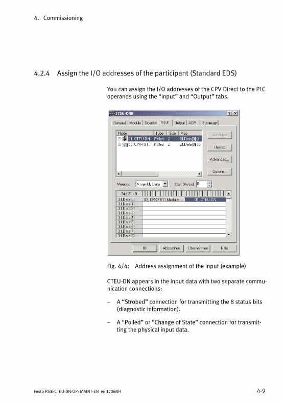
You can assign the I/O addresses of the CPV Direct to the PLCoperands using the “Input” and “Output” tabs.
Fig. 4/4: Address assignment of the input (example)
CTEU-DN appears in the input data with two separate commu-nication connections:
– A “Strobed” connection for transmitting the 8 status bits(diagnostic information).
– A “Polled” or “Change of State” connection for transmit-ting the physical input data.

4. Commissioning
4-10 Festo P.BE-CTEU-DN-OP+MAINT-EN en 1206NH
Fig. 4/5: Address assignment of the output (example)
4.2.5 Loading the configuration into the scanner.
Finally, load the configuration data into the scanner. Furtherinformation can be found in the documentation for your scan-ner.

4. Commissioning
4-11Festo P.BE-CTEU-DN-OP+MAINT-EN en 1206NH
4.3 Parameterisation
NoteObserve the subsequent sections to ensure that the para-meterisation required for your application is automaticallyrestored at switch-on, after a restart or after a device re-placement.
Check which settings are required, especially before adevice replacement. Make sure that these settings areretained or restored (e.g. by the higher-ordercontroller/PLC) Section 2.3.
4.3.1 Methods of parameterisation
CTEU-DN can be parameterised as follows ( Tab. 4/15):
– via the configuration program
– via the scanner
– via the user program
Use the QuickConnect and Automatic Device Replacement(ADR) DeviceNet functions or communication and program-ming via Explicit Messaging, in order to set the required para-meters.
In this case, the PLC automatically transmits the programmedparameters to the bus node after switch-on. The settings willthen be retained even after a restart or device replacement.
NoteThe last parameterisation received in the CTEU-DN is al-ways valid.

4. Commissioning
4-12 Festo P.BE-CTEU-DN-OP+MAINT-EN en 1206NH
Method Description Benefits Disadvantages
Parameterisationvia the configurati-on program(e.g. RSNetWorx)
Parameters set via theconfiguration program anddirect transmission to theDeviceNet participant,local saving in the busnode CTEU-DN
Fast, simple parame-trizing during com-missioning for testingthe parameters
Parameters (locally sa-ved data) are lost aftera restart or device re-placement(For information on de-vice replacement Section 2.3)
Parameterisationvia the scanner(automatic restoreafter restart, Confi-guration Recoveryvia QuickConnectand ADR)
Parameters set via the con-figuration program andtransmission to thescanner:The parameters are trans-mitted from the scanner tothe DeviceNet participantafter every restart (“PowerOn”).
Parameters are reloa-ded automaticallyafter every restart andare therefore also re-tained if the device re-placed
Requirement:The scanner must sup-port ADR
Parameterisationvia the user pro-gram (communica-tion and program-ming via explicitmessaging)
Parameterisation via expli-cit messaging, parametersare saved in the PLC
Parameters are reloa-ded automaticallyafter every restart andare therefore also re-tained if the device re-placed
Requirement:User program required
Tab. 4/15: Methods of parameterisation
4.3.2 Parameterisation with RSNetWorx (with standard EDS)
RSNetWorx enables you to parameterise using the“Parameters” tab of the DeviceNet participant.
This requires the EDS file of the DeviceNet participant to becontained in the EDS library see Section 3.2.4.

4. Commissioning
4-13Festo P.BE-CTEU-DN-OP+MAINT-EN en 1206NH
4
3
1
2
1 “Groups” checkbox for displaying theparameters and data grouped indirectories
2 List of the parameters and data
3 Window for setting the parametervalues
4 Buttons for online display (monitoroperation), uploading anddownloading parameters
Fig. 4/6: Parameterisation examples

4. Commissioning
4-14 Festo P.BE-CTEU-DN-OP+MAINT-EN en 1206NH
Changing parameters Click on a value (Current Value) and change it in the list fieldor in a window that opens separately.
The settings saved in the project are displayed in offlinemode.
Transmitting parameters In online mode, you can transmit the required parameters(“upload”) and then display them (“download”).
Please note:
– The displayed parameters are not automatically updated.
– In online mode too, only the settings and parameter val-ues that are current when called will be displayed.(It takes a certain amount of time to transmit and displaythe values).
– Values that are continuously current are displayed only inmonitor mode, although not with details (no sub-groupsor detailed values).
You can find notes about the specific CTEU-DN parameters inDeviceNet in section 4.3.3.

4. Commissioning
4-15Festo P.BE-CTEU-DN-OP+MAINT-EN en 1206NH
4.3.3 Device-specific parametrisation
The CTEU-DN bus node has device-specific parameters, re-ferred to as parameter objects, e.g. for setting the behaviourof the connected I-port devices or for activating certain statussignals. These parameters can be set in the configurationprogram (“network configurator” “Parameters”).
The type and scope of the parameter objects available inCTEU-DN depends on the connected I-port device.
Use the QuickConnect and Automatic Device Replacement(ADR) DeviceNet functions or communication and program-ming via Explicit Messaging, in order to set the required para-meters ( Section 4.3.1 and Tab. 4/15).
In this case, the controller (PLC) automatically transmits theprogrammed parameters to the bus node after switch-on. Thesettings will then be retained even after a restart or devicereplacement.
To use explicit messaging programming, you need the objectdescriptions and addresses of the DeviceNet object model Appendix A.4.
4.3.4 Behaviour of the inputs and outputs in fail state mode
In case of a control or communication interference, the net-work participants, i.e. the bus nodes and the I-port devices,assume fail state mode.
Possible causes of fail state mode:
– Interference in the control system (PLC/scanner)
– Network/fieldbus interruption (e.g. communication inter-ference, broken cable)
– Interference to data telegrams.

4. Commissioning
4-16 Festo P.BE-CTEU-DN-OP+MAINT-EN en 1206NH
Depending on the DIL switch setting, the inputs and outputshold the last state or reset to the basic state Tab. 2/7.
The selected setting applies for all outputs. (Factory setting:“reset”).
4.3.5 Behaviour of the inputs and outputs in idle state mode
Idle mode is assumed by the network participants when thisis requested by the controller or scanner. The controller isthen in stop mode.
Depending on the DIL switch setting, the outputs hold the laststate or reset to the basic state Tab. 2/7.
The inputs of the network participants continue to be trans-ferred to idle state mode.
The selected setting applies for all inputs and outputs and iscoupled to the setting for the fail state mode. (Factory setting:“reset”).
4.3.6 Parameterisation via a user program (explicit messaging)
Parameter values can also be read and written by the control-ler. To do so, communicate and program via “Explicit Mes-sage”. The required parameter values are specified in a userprogram.
For this parameterisation method, you require device-specificparameter objects and/or the corresponding object descrip-tions Tab. 4/16 and Tab. 4/17. Note that these tables spe-cify only the frames for using parameterisation via explicitmessaging.
Detailed object descriptions and addresses of the DeviceNetobject model can be found in Appendix A.4.

4. Commissioning
4-17Festo P.BE-CTEU-DN-OP+MAINT-EN en 1206NH
Object class Instance Attribute 1) Name
1d 1 - Identity object
2d 1 - Message router
3d 1 - DeviceNet object class
4d 101, 104 - Assembly object
5d 1 - Connection object class
15d 1...16 - Parameter object class
43d 1 - Acknowledge handler class
100d 1...16 - Festo output byte object
101d 1...16 - Festo input byte object
103d 1...2 - Festo diagnostics object
104d 1...2 - Festo module object
105d 1...2 - Festo system object 2)
106d 1...2 - Festo parameter object 3)
1) Information on “Attribute” Tab. 4/17 or Appendix A.42) System information (device-specific data on the bus node)3) This object is device-specific and therefore not contained in the EDS file.
Tab. 4/16: DeviceNet object model for CTEU-DN

4. Commissioning
4-18 Festo P.BE-CTEU-DN-OP+MAINT-EN en 1206NH
Attribute Access Name Type Description 1)
Class attributes
1 Get Revision UINT Revision of the object = 1
2 Get Max instance UINT Max. instance 2) of the CIP object = 2
Instance attributes 2)
1 Get/Set Parameter byte 1 BYTE
2 Get/Set Parameter byte 2 BYTE
3 Get/Set Parameter byte 3 BYTE
4 Get/Set Parameter byte 4 BYTE
5 Get/Set Parameter byte 5 BYTE
6 Get/Set Parameter byte 6 BYTE
7 Get/Set Parameter byte 7 BYTE
8 Get/Set Parameter byte 8 BYTE
NoteWrite access to these objects and instances is possible only if an I-port-compatible device is connec-ted to the corresponding I-port.1) The specific contents (description, “parameters” and “values”) of the objects and instances
depend on the connected I-port device.2) Instance 1 refers to the module indentity of Device 1; Instance 2 to module indentity of Device 2.
Tab. 4/17: DeviceNet object relating to CTEU-DN for the device-specific parameterisation(Festo parameter object) – Class code 106d
Further information on parameter programming with a userprogram (via explicit messaging) can be found in the data onyour controller.

4. Commissioning
4-19Festo P.BE-CTEU-DN-OP+MAINT-EN en 1206NH
4.4 Checklist for commissioning
Observance of the following points helps you to avoid errorsduring commissioning on DeviceNet.
• Finally check the DIL switch settings again.
• Check the address assignment of the inputs and outputs.Check the configured address range (process data andassigned input and output bytes).
• Test the inputs and outputs if necessary.
• Check the parameterisation, via the configuration pro-gram for example.
• Make sure that the desired parameterisation is restoredafter a restart or after fieldbus interruptions.

4. Commissioning
4-20 Festo P.BE-CTEU-DN-OP+MAINT-EN en 1206NH

Diagnostics
5-1Festo P.BE-CTEU-DN-OP+MAINT-EN en 1206NH
Chapter 5
Diagnostics

5. Diagnostics
5-2 Festo P.BE-CTEU-DN-OP+MAINT-EN en 1206NH
Contents
5. Diagnostics 5-1. . . . . . . . . . . . . . . . . . . . . . . . . . . . . . . . . . . . . . . . . . . . . . . . . . .
5.1 Summary of diagnostics options 5-3. . . . . . . . . . . . . . . . . . . . . . . . . . . . . . . . . . .
5.2 Diagnostics via LED display 5-4. . . . . . . . . . . . . . . . . . . . . . . . . . . . . . . . . . . . . . .
5.2.1 Normal operating status display 5-4. . . . . . . . . . . . . . . . . . . . . . . . . . .
5.2.2 PS-LED status display 5-5. . . . . . . . . . . . . . . . . . . . . . . . . . . . . . . . . . . .
5.2.3 Status display X1-/X2-LEDs 5-6. . . . . . . . . . . . . . . . . . . . . . . . . . . . . . .
5.2.4 Status display MNS-LED 5-8. . . . . . . . . . . . . . . . . . . . . . . . . . . . . . . . . .
5.2.5 I/O-LED status display 5-9. . . . . . . . . . . . . . . . . . . . . . . . . . . . . . . . . . . .
5.3 Reaction to malfunctions in the control system 5-10. . . . . . . . . . . . . . . . . . . . . . .
5.4 Diagnostics via network/fieldbus 5-11. . . . . . . . . . . . . . . . . . . . . . . . . . . . . . . . . .
5.4.1 Diagnostics via configuration software 5-11. . . . . . . . . . . . . . . . . . . . . .
5.4.2 Short circuit/overload 5-13. . . . . . . . . . . . . . . . . . . . . . . . . . . . . . . . . . . .

5. Diagnostics
5-3Festo P.BE-CTEU-DN-OP+MAINT-EN en 1206NH
5.1 Summary of diagnostics options
The following options are available for diagnostics and errorelimination, depending on the bus node configuration:
Diagnosticpossibility
Brief description Benefits Detaileddescription
Diagnostics viaLED display
Bus node LEDs indicateconfiguration errors, hardwareerrors, bus errors, etc.immediately
Fast “on-the-spot”recognition of errors
Section 5.2
Diagnostics viafieldbus
Detailed diagnostics via theDeviceNet network,transmission of diagnosticinformation to the process data
Detailed fault recognition Section 5.3
Tab. 5/1: Diagnostics options
1 DIL switchsettings:– OFF:Diagnosticinformation onlyvia explicitmessaging(factory setting)– ON:Diagnosticsactivated
1
Fig. 5/7: DIL switches for diagnostic information
Further information relating to the DIL switches on the busnode can be found in Part I of the product documentationentitled “Installation and Interface manual”, which is suppliedwith the bus node.
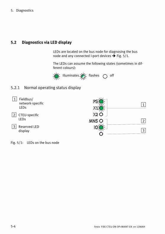
5. Diagnostics
5-4 Festo P.BE-CTEU-DN-OP+MAINT-EN en 1206NH
5.2 Diagnostics via LED display
LEDs are located on the bus node for diagnosing the busnode and any connected I-port devices Fig. 5/1.
The LEDs can assume the following states (sometimes in dif-ferent colours):
Illuminates flashes off
5.2.1 Normal operating status display
1 Fieldbus/network-specificLEDs
2 CTEU-specificLEDs
3 Reserved LEDdisplay
1
2
3
Fig. 5/1: LEDs on the bus node
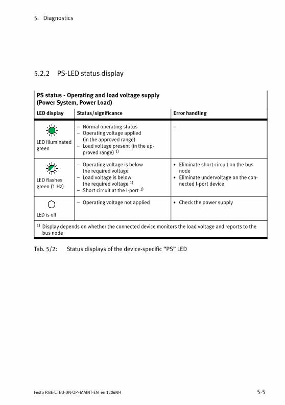
5. Diagnostics
5-5Festo P.BE-CTEU-DN-OP+MAINT-EN en 1206NH
5.2.2 PS-LED status display
PS status - Operating and load voltage supply(Power System, Power Load)
LED display Status/significance Error handling
LED illuminatedgreen
– Normal operating status– Operating voltage applied
(in the approved range)– Load voltage present (in the ap-
proved range) 1)
–
LED flashesgreen (1 Hz)
– Operating voltage is belowthe required voltage
– Load voltage is belowthe required voltage 1)
– Short circuit at the I-port 1)
• Eliminate short circuit on the busnode
• Eliminate undervoltage on the con-nected I-port device
LED is off
– Operating voltage not applied • Check the power supply
1) Display depends on whether the connected device monitors the load voltage and reports to thebus node
Tab. 5/2: Status displays of the device-specific “PS” LED
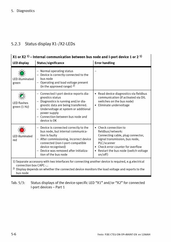
5. Diagnostics
5-6 Festo P.BE-CTEU-DN-OP+MAINT-EN en 1206NH
5.2.3 Status display X1-/X2-LEDs
X1 or X2 1) – Internal communication between bus node and I-port device 1 or 2 1)
LED display Status/significance Error handling
LED illuminatedgreen
– Normal operating status– Device is correctly connected to the
bus node– Operating and load voltage present
(in the approved range) 2)
–
LED flashesgreen (1 Hz)
– Connected I-port device reports dia-gnostics status
– Diagnostics is running and/or dia-gnostic data are being transferred.
– Undervoltage at system or additionalpower supply
– Connection between bus node anddevice is OK
• Read device diagnostics via fieldbuscommunication (if activated via DILswitches on the bus node)
• Eliminate undervoltage
LED illuminatedred
– Device is connected correctly to thebus node, but internal communica-tion is faulty
– After commissioning, incorrect deviceconnected (non-I-port-compatibledevice recognised)
– Device was removed after initializa-tion of the bus node
• Check connection tofieldbus/network:Connecting cable, plug connector,signal transmission, bus node,PLC/scanner
• Check error counter for overflow• Restart the bus node (switch voltage
on/off )
1) Separate accessory with two interfaces for connecting another device is required, e.g.electricalconnection box CAPC-...
2) Display depends on whether the connected device monitors the load voltage and reports to thebus node
Tab. 5/3: Status displays of the device-specific LED “X1” and/or “X2” for connectedI-port devices – Part 1

5. Diagnostics
5-7Festo P.BE-CTEU-DN-OP+MAINT-EN en 1206NH
X1 or X2 1) – Internal communication between bus node and I-port device 1 or 2 1)
LED display Status/significance Error handling
LED is flashingred
– During commissioning, incorrectdevice connected (non-I-port-com-patible device recognised)
– If only LED X1 flashes red: error in thebus node
– If X1 and X2 flash red simultaneously:no I-port device connected to the busnode (at least one device is required)
• Use an I-port compatible device (e.g.valve terminal) from Festo
• Replace bus node• If X1 and X2 flash red simultaneously:
connect I-port device
LED is off
– No device connected to the bus node– Connection is being established
• Connect I-port device
1) Separate accessory with two interfaces for connecting another device is required, e.g.electricalconnection box CAPC-...
2) Display depends on whether the connected device monitors the load voltage and reports to thebus node
Tab. 5/4: Status displays of the device-specific LED “X1” and/or “X2” for connectedI-port devices – Part 2

5. Diagnostics
5-8 Festo P.BE-CTEU-DN-OP+MAINT-EN en 1206NH
5.2.4 Status display MNS-LED
MNS – Module status/network status(Combined Module/Network Status)
LED display Status/significance Error handling
LED illuminatedgreen
– Normal operating status (“online”)– Communication with
fieldbus/network is OK
–
LED flashesgreen (1 Hz)
– Fieldbus/network communicationavailable (“online”), but not con-figured
• Check/configure fieldbus/networkcommunication
LED illuminatedred
– No fieldbus/network communication(not available, “offline”, failed or in-valid bus address or baud rate)
– No voltage supply to bus
• Fieldbus/network is offline:Establish connection
• Fieldbus/network error:Check connection to fieldbus/net-work; connecting cable, plug con-nector, signal transmission, busnode, PLC/scanner
• Check the setting of the DIL switches• Check voltage supply to bus
Section 2.2.3
LED is flashingred
– Communication error:Fieldbus/network communicationdisrupted, bus timeout detected orno voltage supply to bus
• Fieldbus/network error:Check connection to fieldbus/net-work; connecting cable, plug con-nector, signal transmission, busnode, PLC/scanner
• Check the setting of the DIL switches• Check voltage supply to bus
Section 2.2.3
LED is off
– No fieldbus/network connection: not“online”, MAC-ID test “DUB_MAC_ID”did not run successfully or no powersupply to bus
• Establish/check fieldbus/networkconnection
• Correct MAC-ID setting• Check the setting of the DIL switches• Check voltage supply to bus
Section 2.2.3
Tab. 5/5: Status displays of the network-specific “MNS” LED

5. Diagnostics
5-9Festo P.BE-CTEU-DN-OP+MAINT-EN en 1206NH
5.2.5 I/O-LED status display
IO= I/O status, connection status
LED display Status/significance Error handling
LED illuminatedgreen
– Normal operating status– Communication with the controller
(PLC) OK– Bus node is in operational mode and
is controlled by the PLC– IOs are controlled via the PLC via
fieldbus/network
–
LED flashesgreen (1 Hz)
– Operating status in preparation– Bus node is in pre-operational mode– Inputs/outputs (IOs) are in idle state
mode
–
LED illuminatedred
– Inputs/outputs (IOs) are in fail statemode
– Typical cause:usually an unrecoverable softwarefault, e.g. no bus voltage
• Check voltage supply to bus Section 2.2.3
• Read device diagnostics via fieldbuscommunication (if activated via DILswitches on the bus node)
• Eliminate displayed faults
LED is flashingred
– Inputs/outputs (IOs) are in fail statemode
– PLC failure or stop– Incorrect station number in the PLC or
on the bus node (incorrect DIL switchposition)
– Fieldbus/network interruption ormessage failure
• Check PLC• Check station number
NoteStation number (Node ID) 0 is notpermissible!
• Check fieldbus/network connection
LED is off
– Fieldbus/I-port device not connected– Commissioning of the bus node not
complete or not successful
• Connect fieldbus/I-port device• Check fieldbus connection• Restart
Tab. 5/6: Status displays of the fieldbus/network-specific “IO” LED

5. Diagnostics
5-10 Festo P.BE-CTEU-DN-OP+MAINT-EN en 1206NH
5.3 Reaction to malfunctions in the control system
The reaction of outputs and valves to control and communica-tion malfunctions can be set via device-specific parameterisa-tion Section 4.3.4.
In case of a malfunction, the network participants, i.e. the busnodes and the I-port devices, assume the parameterised failstate mode.
Depending on the DIL switch setting, the inputs and outputshold the last state or reset to the basic state Tab. 2/7.
The selected setting applies for all outputs. (Factory setting:“reset”).
NotePlease note the following valve reaction if the outputs arereset after PLC stop, network/fieldbus interruption or othermalfunction:
– Monostable valves move to the basic position
– Double-solenoid valves remain in the current position
– Mid-position valves move to mid-position (pressurized,exhausted or closed, depending on valve type).
WarningDanger of injury.
• Make sure that outputs and valves are moved to a safestate when malfunctions occur.
Incorrect output and valve states can cause dangeroussituations!

5. Diagnostics
5-11Festo P.BE-CTEU-DN-OP+MAINT-EN en 1206NH
5.4 Diagnostics via network/fieldbus
The following diagnostic functions are available:
– Diagnostics via the DeviceNet scanner
– Diagnostics via the configuration software(e.g. RSNetWorx)
– Diagnostics via a user program
5.4.1 Diagnostics via configuration software
1. Make sure that the bus node is “online”.
2. Double-click the CTEU-DN symbol in the configurationsoftware (e.g. RSNetWorx).
3. Click on the “Parameters” tab.
4. Double click on the “Status Byte” parameter line.
Detailed information is displayed Fig. 5/2.
Additional information can be found in Tab. 5/7.

5. Diagnostics
5-12 Festo P.BE-CTEU-DN-OP+MAINT-EN en 1206NH
Fig. 5/2: Display of detailed diagnostics information(example – explanations Tab. 5/7)

5. Diagnostics
5-13Festo P.BE-CTEU-DN-OP+MAINT-EN en 1206NH
The table below shows the composition of the diagnostic in-formation (status byte). Additional information can be foundin the Appendix.
Bit Significance Explanation
0 I-Port Module Error I-port device/module reports diagnostics status
1 I-Port Configuration Error – Connected device/module is not compatible withI-port
– I-port device/module interchanged during opera-tion
– I/O data length not reached/exceeded
2 Communication Error I-port communication error during operation, e.g. ifthe I-port device/module was unplugged
3 Undervoltage PS Undervoltage in the power supply
4 Undervoltage PL I-port device/module reports undervoltage in the loadsupply
5 Overload/Short Circuit Module I-port device/module reports short circuit or overload
6 Overload/Short Circuit I-Port Short circuit or overload at I-port
7 Other Error Other faults:
Tab. 5/7: Explanation on the diagnostic information (significance of I-port status byte –Festo diagnostic object – Class code 103d)
5.4.2 Short circuit/overload
Short circuit or overload monitoring depends on the connec-ted I-port device: When the I-port device monitors the loadvoltage and I-port connection for short circuit and overload,corresponding error messages are generated and forwardedto the PLC. On the bus node, the “PS” LED flashes green,showing a malfunction in the operating and load voltage sup-ply ( Tab. 5/2).More extensive information can be found in the product docu-mentation on the I-port device.

5. Diagnostics
5-14 Festo P.BE-CTEU-DN-OP+MAINT-EN en 1206NH
Error handling
6-1Festo P.BE-CTEU-DN-OP+MAINT-EN en 1206NH
Chapter 6
Error handling

6. Error handling
6-2 Festo P.BE-CTEU-DN-OP+MAINT-EN en 1206NH
Contents
6. Error handling 6-1. . . . . . . . . . . . . . . . . . . . . . . . . . . . . . . . . . . . . . . . . . . . . . . . .
6.1 Fault finding and error elimination 6-3. . . . . . . . . . . . . . . . . . . . . . . . . . . . . . . . .
6.1.1 Check installation 6-3. . . . . . . . . . . . . . . . . . . . . . . . . . . . . . . . . . . . . . .
6.1.2 Check the power supply 6-4. . . . . . . . . . . . . . . . . . . . . . . . . . . . . . . . . .
6.1.3 Restart communication between the bus node and the device 6-5. . .
6.1.4 Check fieldbus communication 6-5. . . . . . . . . . . . . . . . . . . . . . . . . . . . .
6.1.5 Check DeviceNet configuration 6-6. . . . . . . . . . . . . . . . . . . . . . . . . . . . .
6.1.6 Read out diagnostic messages via DeviceNet 6-7. . . . . . . . . . . . . . . . .

6. Error handling
6-3Festo P.BE-CTEU-DN-OP+MAINT-EN en 1206NH
6.1 Fault finding and error elimination
This section is meant as a checklist to help you inspect yourinstallation and commissioning steps if an error occurs. Youwill find information on fault finding and error elimination, aswell as references to the respective chapters of the two-partproduct documentation on the bus node.
Eliminate individual sources of error by running the followingchecks in the specified order.
6.1.1 Check installation
• Check the mechanical and electrical installation of the busnode on the I-port device or the electrical connection boxand the correct earthing of all of the components in-volved.
• Check whether all the required connection lines and con-necting cables are fitted correctly.
• Carefully check potentially faulty lines and cables.
• Replace any visibly damaged lines and cables.
Information relating to installing the bus node can be found inPart I of the product documentation entitled “Installation andInterface manual”, which is supplied with the bus node.In-formation for mounting the bus node on the electrical connec-tion box CAPC-... can be found in the assembly instructionssupplied with the electrical connection box.

6. Error handling
6-4 Festo P.BE-CTEU-DN-OP+MAINT-EN en 1206NH
6.1.2 Check the power supply
Warning• Use only PELV circuits for the electrical power supply inaccordance with IEC/EN 60204-1(Protective Extra-Low Voltage, PELV).
• Observe also the general requirements for PELV circuitsin accordance with IEC/EN 60204-1.
• Use only voltage sources that ensure a reliable electricseparation of operating voltage in accordance withIEC/EN 60204-1.
• Always connect both circuits for operating and loadvoltage supply.
• Check to make sure both power supplies for the operat-ing and load voltage are connected.
NoteThe devices connected to the bus node are powered ex-clusively via the load voltage connection.
• Check the pin assignment of self-assembled cables.
Information relating to installing the bus node can be found inPart I of the product documentation entitled “Installation andInterface manual”, which is supplied with the bus node.
Normal status LED PS-LED illuminates green and the X1-LED and/or X2-LED illu-minate green.
Error status 1 The operating voltage supply for the bus node exhibits under-voltage:
– PS-LED flashes green
6. Error handling
6-5Festo P.BE-CTEU-DN-OP+MAINT-EN en 1206NH
Error status 2 The load voltage supply for the connected device is missingor exhibits undervoltage:
– PS-LED flashes green
and
– X1 and/or X2-LED flash green
NoteRequirement for diagnostics via LED display:The connected device must support this diagnostic function.(Additional information can be found in the respective devicedescription).
6.1.3 Restart communication between the bus node and the device
Problem description: X1 and X2 flash red simultaneously.The check of the mechanicalconnection between bus node and device (dismantling/in-stalling) effected no change. The fault cannot be eliminated inthis way.
Remedy Proceed as follows:
1. Disconnect the operating voltage.
2. Check, sever and re-establish the electrical connectionbetween the bus node and connected devices.
3. Restore voltage.
X1 and/or X2 illuminate or flash green.
6.1.4 Check fieldbus communication
• Compare the desired baud rate with the baud rate set onthe bus node (DIL switch setting).
• Compare the desired station number (NodeID) with thestation number set on the bus node (DIL switch setting).

6. Error handling
6-6 Festo P.BE-CTEU-DN-OP+MAINT-EN en 1206NH
Information relating to installing the bus node can be found inPart I of the product documentation entitled “Installation andInterface manual”, which is supplied with the bus node.
• Compare your cable lengths with the technical data in theAttachment and the recommendation in the CiA specifica-tion ( Tab. 2/8).
• Test the fieldbus communication using the object direct-ory ( Appendix A.4).
Normal status LED MNS-LED is off and I/O-LED illuminates green (in operationalmode).
MNS-LED is off and I/O-LED is off (if no fieldbus communica-tion).
6.1.5 Check DeviceNet configuration
Problem description: Process data are defective.
Remedy Proceed as follows:
1. Check whether the I/O mapping matches the controllersettings ( Appendix A.4).
2. Check whether the bus node status, e.g. operationalmode, matches the controller settings ( Section 5.2.5).
Problem description: Outputs do not switch to the desired state if fieldbus commu-nication is disrupted.
Remedy Proceed as follows:
1. Check whether fail state mode or idle state mode is activ-ated in the controller.
This ensures that the bus node can detect disrupted field-bus communication and that the outputs are set to adefined state after fieldbus communication is restored(network communication).

6. Error handling
6-7Festo P.BE-CTEU-DN-OP+MAINT-EN en 1206NH
2. Check whether Fail State is activated on the bus node (DILswitch position).
Fail state mode off (reset):The outputs are reset to “0” after fieldbus communicationis restored.
Fail state mode on (hold last state):Once fieldbus communication is restored, the outputsresume their state prior to failure.
6.1.6 Read out diagnostic messages via DeviceNet
Problem description: The previous checks are “fruitless”, i.e. provide no informa-tion about the cause of the fault.
Remedy: Read out diagnostic messages via DeviceNet.
Requirement: The I-port devices connected to the bus nodes can offeradvanced diagnostic options.
Additional prerequisites:
– Diagnostic mode is activated:Check the DIL switch setting.
– Network connection to the connected I-port device isavailable:X1 or X2-LED flashes green.
Proceed as follows:
Evaluate the diagnostic information in the process data (seeSection 5.3).

6. Error handling
6-8 Festo P.BE-CTEU-DN-OP+MAINT-EN en 1206NH

Technical appendix
A-1Festo P.BE-CTEU-DN-OP+MAINT-EN en 1206NH
Appendix A
Technical appendix

A. Technical appendix
A-2 Festo P.BE-CTEU-DN-OP+MAINT-EN en 1206NH
Contents
A. Technical appendix A-1. . . . . . . . . . . . . . . . . . . . . . . . . . . . . . . . . . . . . . . . . . . . .
A.1 Technical data A-3. . . . . . . . . . . . . . . . . . . . . . . . . . . . . . . . . . . . . . . . . . . . . . . . . .
A.1.1 General properties A-3. . . . . . . . . . . . . . . . . . . . . . . . . . . . . . . . . . . . . .
A.1.2 Power supply A-6. . . . . . . . . . . . . . . . . . . . . . . . . . . . . . . . . . . . . . . . . . .
A.1.3 Signal transmission A-7. . . . . . . . . . . . . . . . . . . . . . . . . . . . . . . . . . . . . .
A.2 Terms and abbreviations A-8. . . . . . . . . . . . . . . . . . . . . . . . . . . . . . . . . . . . . . . . .
A.3 Fail state behaviour A-11. . . . . . . . . . . . . . . . . . . . . . . . . . . . . . . . . . . . . . . . . . . . .
A.4 DeviceNet object model A-13. . . . . . . . . . . . . . . . . . . . . . . . . . . . . . . . . . . . . . . . . .
A.4.1 DeviceNet Object model for CTEU-DN – overview A-13. . . . . . . . . . . . . .
A.4.2 Participant features (Identity object) A-16. . . . . . . . . . . . . . . . . . . . . . . .
A.4.3 DeviceNet object A-17. . . . . . . . . . . . . . . . . . . . . . . . . . . . . . . . . . . . . . . .
A.4.4 Assembly Object A-18. . . . . . . . . . . . . . . . . . . . . . . . . . . . . . . . . . . . . . . .
A.4.5 Discrete output byte object A-19. . . . . . . . . . . . . . . . . . . . . . . . . . . . . . .
A.4.6 Discrete input byte object A-20. . . . . . . . . . . . . . . . . . . . . . . . . . . . . . . . .
A.4.7 Festo diagnostic object (I-port status byte) A-21. . . . . . . . . . . . . . . . . . .
A.4.8 Festo module object A-23. . . . . . . . . . . . . . . . . . . . . . . . . . . . . . . . . . . . .
A.4.9 Festo system object A-24. . . . . . . . . . . . . . . . . . . . . . . . . . . . . . . . . . . . . .
A.4.10 Festo parameter object A-25. . . . . . . . . . . . . . . . . . . . . . . . . . . . . . . . . . .

A. Technical appendix
A-3Festo P.BE-CTEU-DN-OP+MAINT-EN en 1206NH
A.1 Technical data
A.1.1 General properties
General properties
Protection class through housingTo IEC/EN 60529, bus node fully mounted, plugconnector inserted or provided with protectivecap
IP65/67 1) 2)
With corresponding connecting cable from theFesto range of accessories
Protection against electric shockProtection against direct and indirect contact inaccordance with IEC/EN 60204-1
through the use of PELV circuits
SeparationBus signals,DeviceNet interface to UEL/SEN 3)
All bus signals, including V– (“CAN_GND”) andV+ (“CAN_V+”), are galvanically isolated
Electromagnetic compatibility (EMC) 2)
– Emitted interference– Resistance to interference
See declaration of conformitywww.festo.com
Temperature rangeAmbient temperature– Operation– Storage/transport
–5 … +50 °C–20 … +70 °C
Relative air humidityTo IEC 60770
93 % at 40 °C
Corrosion protection Intended for indoor application in typical indus-trial atmosphere. Condensation may occur.
1) Note that the connected devices may conform to a lower protection class or a lower temperaturerange etc.
2) The bus node is intended for use in an industrial environment.Outside of industrial environments, e.g. in commercial and mixed-residential areas, actions tosuppress interference may have to be taken.
3) UEL/SEN is also designated in other technical documentation as VEL/SEN
Tab. A/1: General characteristics (Part 1)

A. Technical appendix
A-4 Festo P.BE-CTEU-DN-OP+MAINT-EN en 1206NH
General properties
Vibration and shock resistanceto IEC/EN 60068 1)
– Vibration (part 2 - 6)– Shock (part 2 - 27)– Continuous shock (part 2 – 29)
Severity level (SG) 1)
Wall or H-rail mounting– Wall: SG2; H-rail: SG1– Wall: SG2; H-rail: SG1– Wall: SG1; H-rail: SG1
Materials– Housing– Housing cover, fibre-optic cable,
DIL switch cover– Threaded sleeve M12– Threaded bush M3– Seals– Screws
RoHS-compliantPolyamide (PA), reinforcedPolycarbonate (PC)
Brass, galvanically nickel-platedBrassNitrile rubber (NBR)Galvanised steel
Dimensions– Width– Height– Length
40 mm50 mm91 mm
WeightBus node without connecting cable and sub-structure
90 g
1) Explanation of the severity level Tab. A/3 below “Explanation of vibration and shock - severity level”
Tab. A/2: General characteristics (Part 2)

A. Technical appendix
A-5Festo P.BE-CTEU-DN-OP+MAINT-EN en 1206NH
Explanation on vibration and shock – severity level
Severity level 1(SG1, to IEC/EN 60068,Part 2 – 29)
Vibration:0.15 mm path at 10 … 58 Hz;2 g acceleration at 58 ... 150 Hz
Shock:±15 g at 11 ms duration;5 shocks per direction
Continuous shock:± 15 g at 6 ms duration;1000 shocks per direction
Severity level 2(SG2, to IEC/EN 60068,Part 2 – 27)
Vibration:0.35 mm path at 10 … 60 Hz;5 g acceleration at 60 ... 150 Hz
Shock:±30 g at 11 ms duration;5 shocks per direction
Continuous shock:n. a.
Tab. A/3: Explanation on vibration and shock resistance (severity level)

A. Technical appendix
A-6 Festo P.BE-CTEU-DN-OP+MAINT-EN en 1206NH
A.1.2 Power supply
Power supply
Operating voltage (reverse polarity protected)for bus nodes and connected I-port devices 1)
– Nominal value– Tolerance range
DC 24 V ± 25 %DC 18 …30 V
Load voltage (reverse polarity protected) forconnected I-port devices 1)
– Maximum value– Typical tolerance range
(device-dependent) 2)
max. DC 30 VDC 18 …30 V 2)
Voltage supply to the bus (fieldbus interface,reverse polarity protected)– Tolerance range– Current consumption, interface electronics
DC 11 …30 Vmax. 50 mA
Bus node own-current consumptionfrom operating voltage supply for electronics/sensors (UEL/SEN)
max. 65 mA at 24 V(internal electronics)
Load capacity of the operating and load voltagesupply 1) 3)
– Bus node on I-port device (e.g. valve terminal)– Bus node on electrical connection box, type
CAPC-...
max. 4 Amax. 2 A per connection (X1/X2)
Mains buffering time 10 ms
1) Separate, external fuses are required for operating and load voltage supply2) Dependent on the connected I-port devices (e.g. valve terminal)3) Load capacity for the connected I-port devices, e.g. the valve terminal, including the bus node
Tab. A/4: Power supply

A. Technical appendix
A-7Festo P.BE-CTEU-DN-OP+MAINT-EN en 1206NH
A.1.3 Signal transmission
I-port interface signal transmission
– Internal cycle time 1 ms per 1 byte of user data
Maximum effective data rate (baud rate)dependent on the line length (reference values)
Main busline 1)
Branch line 2) baud rate 3)
Individualbranch line
All branch lines (total)
Max. 100 m Max. 6 m Max. 39 m 500 kBaud
Max. 250 m Max. 6 m Max. 78 m 250 kBaud
Max. 500 m Max. 6 m Max. 156 m 125 kBaud
1) Trunk line2) Drop line3) The setting of the baud rate depends on the length of all network lines.
• Consider the length of the fieldbus line between the PLC and bus node (main bus line) as well asthe length of possibly available branch lines and branches (for continued fieldbus configurati-on).
• Also consider the overall length (sum) of all branch lines.• The subsequent table supplies reference values for the maximum baud rate, dependent on the
line lengths. The baud rates named here are not supported by all controllers.• Observe possibly deviating specifications in the manual of your control system or network
scanner. Further information can be found in the specifications of the ODVAwww.odva.org.
Tab. A/5: Signal transmission (technical data)
NoteTechnical data of the connected equipment can be found inthe respective product documentation.

A. Technical appendix
A-8 Festo P.BE-CTEU-DN-OP+MAINT-EN en 1206NH
A.2 Terms and abbreviations
The following product and network-specific terms and abbre-viations are used in this description:
Abbreviation/term Significance
Bus nodes Create the connection to certain fieldbuses or networks, pass on controlsignals to the connected devices or modules and monitor theirfunctionality
COB-ID Communication Object Identifiers comprise the function code and addressof the activated fieldbus/network participant (station number, node ID)
DIL switches Miniature switches; dual-in-line switches usually comprise several switchelements that can be used to make hardware settings
DCF Device Configuration Files contain additional project data over and abovethe content and scope of an Electronic Data Sheet (EDS) see also“EDS”
EDS Electronic Data Sheets contain product-specific data, e.g. the bus nodecharacteristics see also “DCF”
EDS library Manages the characteristics of the various fieldbus/network participants
F0h Hexadecimal numbers are identified by a subscript “H”
Fail state Bus node function, also referred to as “fail safe” function; defines thestate assumed by outputs or valves following network or communicationerrors, activates for example a reset of the outputs - or alternatively holdsthe last state
I Input
I/O Input/output, also designated “I/O”
Tab. A/6: System-specific terms and abbreviations (General overview – Part 1)

A. Technical appendix
A-9Festo P.BE-CTEU-DN-OP+MAINT-EN en 1206NH
Abbreviation/term Significance
I/O diagnosticsinterface
Diagnostic interface at I/O level, which enables access to the internal dataof the bus node and the connected devices or modules
IPC Industrial PC
I-port I-port is a Festo-specific interface for transmitting communication data(process data, sensor signals, pilot signals) and supply voltages. TheI-port communication protocol is based on the IO link protocol. Theelectrical and mechanical link between bus nodes and I-port device isstandardised.
Load voltage Comprises the voltage supply for connected devices and outputs,e.g. I-port devices, electrical analogue or digital outputs, solenoid coils ofvalves etc. (load voltage supply see also “Operating voltage”: Voltagesupply for electronics and sensors)
O Output
Object Directory Makes all important fieldbus/network participant parameters accessiblein a standardised manner
ODVA Open Device Vendor Association, DeviceNet umbrella organisation
Operating voltage Also referred to as signal voltage; comprises the voltage supply for theelectronics/sensors (power supply see also “Load voltage”: voltagesupply for outputs)
PDO Process Data Objects facilitate the fast transmission of process data viaMulticast connection and are transmitted by simple DeviceNet messageswithout protocol overhead; PDOs can be transmitted event-controlled,synchronised with a system cycle or on request; a distinction is drawnbetween “TPDOs” and “RPDOs”
PELV (ProtectiveExtra-Low Voltage)
Protective Extra-Low Voltage
Tab. A/7: System-specific terms and abbreviations (General overview – Part 2)

A. Technical appendix
A-10 Festo P.BE-CTEU-DN-OP+MAINT-EN en 1206NH
Term/abbreviation Significance
PLC Programmable logic controller, also referred to as system controller orcontroller for short, equivalent to “Programmable Logic Controller”( PLC)
Power supply Umbrella term for operating and load voltage supplies
RPDO Receive PDO
RSNetWorx Configuration, parameterisation, commissioning and diagnostics softwarefor DeviceNet from Rockwell Automation/Allen-Bradley
SC/O, SCS, SCO, SCV Short circuit/overload, short circuit/overload sensor supply or outputs orvalves
SDO Service Data Objects predominantly form point-to-point connectionsbetween the server and client for the exchange of parameters for deviceconfiguration. permit write and read access for every entry in the Object directory of a bus node see also “PDO”
Station number Address of the fieldbus/network participant, as referred to as Node ID
TPDO Transmit PDO
Tab. A/8: System-specific terms and abbreviations (General overview – Part 3)

A. Technical appendix
A-11Festo P.BE-CTEU-DN-OP+MAINT-EN en 1206NH
A.3 Fail state behaviour
The parameterisation of the fail state mode regulates thebehaviour of the bus node and the connected I-port devicesin the event of communication errors ( Section 4.3.4 and5.3).
NoteThe fail state mode requires the corresponding DeviceNetfunction to be activated in the PLC.
Behaviour Settings Processing Diagnostics
of the busnode/field-bus
of the connec-ted I-portdevice
of the fail statemode (DILswitches)
of the incoming PLCcontrol signals forOUT/VAL
OK Timeout OFF I/Os are reset – Bus nodes LED X1and/or LED X2 illu-minate/illuminatered
– Master controller re-ports a connectionfault
ON I/Os remain set(“Hold last state”)
Timeout OK OFF I/Os are reset – Bus node LEDMNSilluminates red
ON I/Os remain set(“Hold last state”)
Timeout OFF I/Os are reset – Bus nodes LED X1and/or LED X2 illu-minate/illuminatered
– Bus node LEDMNSilluminates red
ON I/Os remain set(“Hold last state”)
Tab. A/9: Fail state behaviour in dependence of bus nodes/field bus, I-port device andfail state mode setting

A. Technical appendix
A-12 Festo P.BE-CTEU-DN-OP+MAINT-EN en 1206NH
1
1 DIL switch settings:– OFF = reset (factory setting)– ON = Hold last state
Fig. A/3: DIL switches for Fail state function
The DIL switch setting applies for all outputs.
Further information relating to the DIL switches on the busnode can be found in Part I of the product documentationentitled “Installation and Interface manual”, which is suppliedwith the bus node.

A. Technical appendix
A-13Festo P.BE-CTEU-DN-OP+MAINT-EN en 1206NH
A.4 DeviceNet object model
This chapter describes the representation of the CTEU-DNwithin the DeviceNet Object model. This DeviceNet-specificinformation is provided primarily in English to enable aunique reference to be made to DeviceNet specifications andother technical documentation.
A.4.1 DeviceNet Object model for CTEU-DN – overview
Fig. A/1: DeviceNet Object model for CTEU-DN

A. Technical appendix
A-14 Festo P.BE-CTEU-DN-OP+MAINT-EN en 1206NH
Object model, object classes
The following object classes are supported in the DeviceNetobject model for CTEU-DN:
Object class Instance Attribute 1) Name
1d 1 - Identity object
2d 1 - Message router
3d 1 - DeviceNet object class
4d 101, 104 - Assembly object
5d 1 - Connection object class
15d 1...16 - Parameter object class
43d 1 - Acknowledge handler class
100d 1...16 - Festo output byte object
101d 1...16 - Festo input byte object
103d 1...2 - Festo diagnostics object
104d 1...2 - Festo module object
105d 1...2 - Festo system object 2)
106d 1...2 - Festo parameter object 3)
1) Information on “Attribute” Tab. 4/172) System information (device-specific data on the bus node)3) This object is device-specific and therefore not contained in the EDS file.
Tab. A/10: DeviceNet Object model for CTEU-DN – Object classes

A. Technical appendix
A-15Festo P.BE-CTEU-DN-OP+MAINT-EN en 1206NH
Class services, Instance services
CTEU-DN supports the following Class services and Instanceservices:
Service code Service name
05d (0x05) Reset
14d (0x0E) Get Attribute Single
16d (0x10) Set Attribute Single
Tab. A/11: Class services
Communication options
The following message types are supported by CTEU-DN inDeviceNet:
– Change of state / Cyclic communication
– Polled communication (“I/O polling”)

A. Technical appendix
A-16 Festo P.BE-CTEU-DN-OP+MAINT-EN en 1206NH
A.4.2 Participant features (Identity object)
Object class: 1dInstances: 1
The Identity object identifies and describes the DeviceNetparticipant CTEU-DN.
Attribute Access Name Type Description Value
Class attributes
1 Get Revision UINT Revision of theobject
1
2 Get Max instance UINT Max. instance 2) ofthe CIP object
1
Instance attributes
1 Get Vendor ID UINT Vendor identifica-tion
Festo SE & Co. KG26d (0x1A)
2 Get Device type UINT General type ofthe product
Communicationinterface12d (0xC)
3 Get Product code UINT 6000d (0x1770)
4 Get Revision STRUCT Firmware revision
Major revision USINT
Minor revision USINT
5 Get Status WORD Summary status ofthe device
(according to CIPspecification)
6 Get Serial number UDINT
7 Get Product name SHORT_STRING
CTEU-DN
8 Get State USINT Current state ofdevice
(according to CIPspecification)
Tab. A/12: Participant features (Identity object) – Class code 1d

A. Technical appendix
A-17Festo P.BE-CTEU-DN-OP+MAINT-EN en 1206NH
A.4.3 DeviceNet object
Object class: 3d
Attribute Access Name Type Description Value
Class attributes
1 Get Revision UINT Revision of the object 2
Instance attributes
1 Get MAC ID USINT “MAC address” (DeviceNetaddress/stationnumber/Node ID)
0 … 63
2 Get Baud rate USINT Baud rate
3 Get/Set Bus off interrupt(BOI)
BOOL Communication interruption(Event, optional)
4 Get/Set Bus off counter USINT Number of communicationinterruptions(Event counter, optional)
6 Get MAC ID switchchanged
BOOL Significance: The setting ofthe “MAC-ID” DIL switch(station number) haschanged since last beingstarted
7 Get Baud rate switchchanged
BOOL Significance: The setting ofthe baud rate DIL switch(data rate) has changedsince last being started
8 Get MAC ID switchvalue
USINT Current value of the“MAC-ID” switch
9 Get Baud rate switchvalue
USINT Current value of the baudrate switch
10 Get/Set Quick connect BOOL
Tab. A/13: DeviceNet object – Class code 3d

A. Technical appendix
A-18 Festo P.BE-CTEU-DN-OP+MAINT-EN en 1206NH
A.4.4 Assembly Object
Object class: 4d
Attribute Access Name Type Description Value
Class attributes
1 Get Revision UINT Revision of the object 2
2 Get NumberofInstances
UINT Max. instance of the CIP object 2
Instance 100 - Attributes
Get/Set Data ARRAYOFBYTE
Contains all output data, refers to Class 100,Instance 1...n, Attribute 3 (n = number of out-put bytes)
Get Size UINT Number of bytes in Attribute 3
Instance 101 - Attributes
3 Get Data ARRAYOFBYTE
Contains all input data and optional diagnost-ic information.If diagnostics activated (DIL-switches):– Class 103, Instance 1, Attribute 1
(status byte I-port 1)– Class 103, Instance 2, Attribute 1
(status byte I-port 2)– Class 101, Instance 1...n, Attribute 3
(n = number of input bytes)If diagnostics not activated:– Class 101, Instance 1...n, Attribute 3
(n = number of input bytes)
4 Get Size UINT Number of bytes in Attribute 3
Tab. A/14: Assembly object – Class code 4d

A. Technical appendix
A-19Festo P.BE-CTEU-DN-OP+MAINT-EN en 1206NH
A.4.5 Discrete output byte object
Object class: 100d
Attribute Access Name Type Description Value
Class attributes
1 Get Revision UINT Revision of the object 2
2 Get Maxinstances
UINT Max. instance of the CIP object 32
8 Get/Set Alloutputs
ARRAYOFBYTE
All outputs 2
Instances
1 … 8
9 … 16
17 … 32
Instances 1 … 8:Outputs, 8 bytes (4 words)Instances 9 … 16:Reserved for max. 128 outputs at I-portInstances 17 … 32:ReservedNoteThe channels of I-port 1 are assigned first,then the channels of I-port 2.
Instance attributes
3 Get/Set Value BYTE Output value of the outputs
Tab. A/15: Discrete output byte object – Class code 100d

A. Technical appendix
A-20 Festo P.BE-CTEU-DN-OP+MAINT-EN en 1206NH
A.4.6 Discrete input byte object
Object class: 101d
Attribute Access Name Type Description Value
Class attributes
1 Get Revision UINT Revision of the object 1
2 Get Maxinstances
UINT Max. instance of the CIP object 34
8 Get All inputs ARRAYOFUSINT
All inputs
Instances
1 … 8
9 … 16
17 … 32
Instances 1 … 8:Inputs, 8 byte (4 words)Instances 9 … 16:Reserved for max. 128 inputs at I-portInstances 17 … 32:ReservedNoteThe channels of I-port 1 are assigned first,then the channels of I-port 2.
Instance attributes
3 Get Value BYTE Input value for the inputs
Tab. A/16: Discrete input byte object – Class code 101d

A. Technical appendix
A-21Festo P.BE-CTEU-DN-OP+MAINT-EN en 1206NH
A.4.7 Festo diagnostic object (I-port status byte)
Object class: 103d
Attribute Access Name Type Description Value
Class attributes
1 Get Revision UINT Revision of the object 1
2 Get Max instances UINT Max. instance of the CIP object 2
Instances
1
2
Instance 1:Module diagnostics – I-port device 1(“Device 1”)Instance 2:Module diagnostics – I-port device 2(“Device 2”)
Instance attributes
1 Get I-port status byte BYTE I-port status byte:Significance/explanation Tab. A/18
2 Get Diagnostic byte 1 BYTE Transmission of diagnostics informa-tion from the I-port device - byte 1
3 Get Diagnostic byte 2 BYTE Transmission of diagnostics informa-tion from the I-port device - byte 2
Tab. A/17: Festo diagnostic object (I-port status byte) – Class code 103d

A. Technical appendix
A-22 Festo P.BE-CTEU-DN-OP+MAINT-EN en 1206NH
Bit Significance Explanation
0 I-Port Module Error I-port device/module reports diagnostics status
1 I-Port Configuration Error – Connected device/module is not compatible withI-port
– I-port device/module interchanged duringoperation
– I/O data length not reached/exceeded
2 Communication Error I-port communication error during operation, e.g. ifthe I-port device/module was unplugged
3 Undervoltage PS Undervoltage in the power supply
4 Undervoltage PL I-port device/module reports undervoltage in the loadsupply
5 Overload/Short Circuit Module I-port device/module reports short circuit or overload
6 Overload/Short Circuit I-Port Short circuit or overload at I-port
7 Other Error Other faults
Tab. A/18: I-port status byte – Significance and explanation of the diagnostics informa-tion (Festo diagnostic object – Class code 103d)

A. Technical appendix
A-23Festo P.BE-CTEU-DN-OP+MAINT-EN en 1206NH
A.4.8 Festo module object
Object class: 104d
Attribute Access Name Type Description Value
Class attributes
1 Get Revision UINT Revision of the object 1
2 Get Max instances UINT Max. instance of the CIP object 2
3 Get Total inputlength
USINT Process data: input length of allports
4 Get Total outputlength
USINT Process data: output length of allports
Instances
1
2
Access to connected I-portdevices:– Instance 1:
Module identity – I-port device 1– Instance 2:
Module identity – I-port device 2
Instance attributes
1 Get Product name SHORT_STRING
2 Get Device ID UDINT (Value = 0, if no I-port device con-nected)
3 Get Process datainput
USINT Number of inputs I in byte
4 Get Process dataoutput
USINT Number of outputs O in byte
5 Get Serial number UDINT
Tab. A/19: Festo module object – Class code 104d

A. Technical appendix
A-24 Festo P.BE-CTEU-DN-OP+MAINT-EN en 1206NH
A.4.9 Festo system object
Object class: 105dInstances: 1
Attribute Access Name Type Description Value
Class attributes
1 Get Revision UINT Revision of the object 1
2 Get Max instances UINT Max. instance of the CIP object 1
Instance
1 Access to system information(Data in the bus node)
Instance attributes
1 Get Product name SHORT_STRING
CTEU-DN
2 Get Process datainput
USINT Total number of inputs I in byte(Device 1 + 2)
3 Get Process dataoutput
USINT Total number of inputs I in byte(Device 1 + 2)
4 Get Serial number UDINT
Tab. A/20: Festo module object – Class code 105d

A. Technical appendix
A-25Festo P.BE-CTEU-DN-OP+MAINT-EN en 1206NH
A.4.10 Festo parameter object
Object class: 106d
The Festo parameter object is a DeviceNet object relating toCTEU-DN for the device-specific parameterisation.
Attribute Access Name Type Description 1) Value
Class attributes
1 Get Revision UINT Revision of the object 1
2 Get Max instance UINT Max. instance 2) of theCIP object
2
Instance attributes 2)
1 Get/Set Parameter byte 1 BYTE
2 Get/Set Parameter byte 2 BYTE
3 Get/Set Parameter byte 3 BYTE
4 Get/Set Parameter byte 4 BYTE
5 Get/Set Parameter byte 5 BYTE
6 Get/Set Parameter byte 6 BYTE
7 Get/Set Parameter byte 7 BYTE
8 Get/Set Parameter byte 8 BYTE
NoteWrite access to these objects and instances is possible only if an I-port-compatible device is connec-ted to the corresponding I-port.1) The specific contents (description, “parameters” and “values”) of the objects and instances de-
pend on the connected I-port device.2) Instance 1 refers to the module indentity of Device 1; Instance 2 to module indentity of Device 2.
Tab. A/21: Festo parameter object – Class code 106d

A. Technical appendix
A-26 Festo P.BE-CTEU-DN-OP+MAINT-EN en 1206NH

Index
B-1Festo P.BE-CTEU-DN-OP+MAINT-EN en 1206NH
Appendix B
Index

B. Index
B-2 Festo P.BE-CTEU-DN-OP+MAINT-EN en 1206NH
Contents
B. Index B-1. . . . . . . . . . . . . . . . . . . . . . . . . . . . . . . . . . . . . . . . . . . . . . . . . . . . . . . . .

B. Index
B-3Festo P.BE-CTEU-DN-OP+MAINT-EN en 1206NH
Index
A
Abbreviations, Product-specific XII, A-8. . . . . . . . . . . . . . . . .
Approvals VIII. . . . . . . . . . . . . . . . . . . . . . . . . . . . . . . . . . . . . .
C
CE marking VIII. . . . . . . . . . . . . . . . . . . . . . . . . . . . . . . . . . . . .
COB-ID A-12. . . . . . . . . . . . . . . . . . . . . . . . . . . . . . . . . . . . . . .
Communication, Check 6-5. . . . . . . . . . . . . . . . . . . . . . . . . . . .
D
Designated use VII. . . . . . . . . . . . . . . . . . . . . . . . . . . . . . . . . .
Diagnostic byte 5-13, A-21, A-22. . . . . . . . . . . . . . . . . . . . . . .
DiagnosticsFieldbus 5-11. . . . . . . . . . . . . . . . . . . . . . . . . . . . . . . . . . . .LEDs 5-4. . . . . . . . . . . . . . . . . . . . . . . . . . . . . . . . . . . . . . . .Messages via CANopen 6-7. . . . . . . . . . . . . . . . . . . . . . . . . .
DIL switchesDiagnostics 5-3. . . . . . . . . . . . . . . . . . . . . . . . . . . . . . . . . . . .Function A-11. . . . . . . . . . . . . . . . . . . . . . . . . . . . . . . . . . . .Switching positions A-11. . . . . . . . . . . . . . . . . . . . . . . . . . .
E
EDS library 1-6. . . . . . . . . . . . . . . . . . . . . . . . . . . . . . . . . . . . . .
ErrorFail state A-11. . . . . . . . . . . . . . . . . . . . . . . . . . . . . . . . . . . .Locate and eliminate 6-3. . . . . . . . . . . . . . . . . . . . . . . . . . . .

B. Index
B-4 Festo P.BE-CTEU-DN-OP+MAINT-EN en 1206NH
F
Fail state 4-15, A-11. . . . . . . . . . . . . . . . . . . . . . . . . . . . . . . . . .Function A-11. . . . . . . . . . . . . . . . . . . . . . . . . . . . . . . . . . . .Mode A-11. . . . . . . . . . . . . . . . . . . . . . . . . . . . . . . . . . . . . . .
I
I/O-LED 5-9. . . . . . . . . . . . . . . . . . . . . . . . . . . . . . . . . . . . . . . . .
Idle state 4-16. . . . . . . . . . . . . . . . . . . . . . . . . . . . . . . . . . . . . .
Instructions on the description IX. . . . . . . . . . . . . . . . . . . . . . .
L
Layout, Check 6-6. . . . . . . . . . . . . . . . . . . . . . . . . . . . . . . . . . . .
LEDs 5-4. . . . . . . . . . . . . . . . . . . . . . . . . . . . . . . . . . . . . . . . . .I/O-LED 5-9. . . . . . . . . . . . . . . . . . . . . . . . . . . . . . . . . . . . . . .MNS-LED 5-8. . . . . . . . . . . . . . . . . . . . . . . . . . . . . . . . . . . . . .Operating status display 5-4. . . . . . . . . . . . . . . . . . . . . . . .PS-LED 5-5. . . . . . . . . . . . . . . . . . . . . . . . . . . . . . . . . . . . . . . .X1/X2-LEDs 5-6. . . . . . . . . . . . . . . . . . . . . . . . . . . . . . . . . . . .
M
MNS-LED 5-8. . . . . . . . . . . . . . . . . . . . . . . . . . . . . . . . . . . . . . . .
P
Pictograms XI. . . . . . . . . . . . . . . . . . . . . . . . . . . . . . . . . . . . . . .
PS-LED 5-5. . . . . . . . . . . . . . . . . . . . . . . . . . . . . . . . . . . . . . . . .
R
RSNetWorx 5-11. . . . . . . . . . . . . . . . . . . . . . . . . . . . . . . . . . . .

B. Index
B-5Festo P.BE-CTEU-DN-OP+MAINT-EN en 1206NH
S
Service IX. . . . . . . . . . . . . . . . . . . . . . . . . . . . . . . . . . . . . . . . . .
Status byte 5-13, A-21, A-22. . . . . . . . . . . . . . . . . . . . . . . . . . .
T
Target group VIII. . . . . . . . . . . . . . . . . . . . . . . . . . . . . . . . . . . .
Text designations XI. . . . . . . . . . . . . . . . . . . . . . . . . . . . . . . . . .
U
User instructions X. . . . . . . . . . . . . . . . . . . . . . . . . . . . . . . . . .
X
X1/X2-LEDs 5-6. . . . . . . . . . . . . . . . . . . . . . . . . . . . . . . . . . . . . .

B. Index
B-6 Festo P.BE-CTEU-DN-OP+MAINT-EN en 1206NH