universal cvr 30 im 23-70-03_rev_1
DESCRIPTION
Manual de instalacionTRANSCRIPT

CVR-30B and CVR-120Solid-State
COCKPIT VOICE RECORDER
Installation Manual
© 1996, 1997, 1998 UNIVERSAL AVIONICS SYSTEMS CORPORATIONALL RIGHTS RESERVED
3260 East Lerdo RoadTucson, AZ 85706(520) 295-2300 • (800) 321-5253 23-70-03 Revised January 20, 1998
CVR-30B and CVR-120 Installation Manual
Page 123-70-03 January 20, 1998
Record of RevisionsRev. No. Issue Date Insertion Date Initials
1 1/20/98 1/20/98 ARO
Retain this record in front of the manual. Upon receipt of revision, insert and remove pages according to the List ofEffective Pages. Then enter, on this page, the revision number, issue date, insertion date, and your initials.

CVR-30B and CVR-120 Insta lla tion Manua l
Page 1 23-70-03 January 20, 1998
Record of Temporary Revisions
Rev. No. Issue Date Insertion Date & Initials Removal Date & Initials
23.70.03-1 2/26/98 2/26/98 / UASC
23.70.03-2 3/23/98 3/23/98 / UASC
23.70.03-3 10/15/98 10/15/98 / UASC
23.70.03-4 10/15/98 10/15/98 / UASC 3/21/00/UASC/TC-7
23.70.03-5 6/9/99 6/9/99 / UASC
23.70.03-6 3/21/00 3/21/00 / UASC
23.70.03-7 3/21/00 3/21/00 / UASC
23.70.03-8 3/21/00 3/21/00 / UASC
Retain this record in front of the manual. Upon receipt of revision, insert pages into manual and enter, on this page, the revision number, issue date, insertion date, and your initials. Also, record the removal of each temporary revision you remove.

CVR-30B and CVR-120 Installation Manual
Page 1LIST OF EFFECTIVE PAGES January 20, 1998
List of Effective PagesFor your convenience, this manual has been reprinted in its entirety including Revision 1.
SUBJECT PAGE DATETitle Page Jan 20/98Record of Revisions 1 Jan 20/98Record of TemporaryRevisions 1 Jan 20/98List of Effective Pages 1 Jan 20/98Table of Contents 1 Jan 20/98
2 Jan 20/983 Jan 20/98
Introduction 1 Jan 20/98Description and Operation 1 Jan 20/98
2 Jan 20/983 Jan 20/984 Jan 20/985 Jan 20/98
FAA Approval 101 Jan 20/98102 Jan 20/98103 Jan 20/98104 Jan 20/98105 Jan 20/98106 Jan 20/98107 Jan 20/98108 Jan 20/98109 Jan 20/98110 Jan 20/98
Equipment Specifications 201 Jan 20/98202 Jan 20/98203 Jan 20/98204 Jan 20/98205 Jan 20/98206 Jan 20/98207 Jan 20/98208 Jan 20/98209 Jan 20/98210 Jan 20/98211 Jan 20/98212 Jan 20/98213 Jan 20/98214 Jan 20/98215 Jan 20/98216 Jan 20/98
SUBJECT PAGE DATE217 Jan 20/98218 Jan 20/98
Installation and Wiring 301 Jan 20/98302 Jan 20/98303 Jan 20/98304 Jan 20/98305 Jan 20/98306 Jan 20/98307 Jan 20/98308 Jan 20/98309 Jan 20/98310 Jan 20/98311 Jan 20/98312 Jan 20/98313 Jan 20/98314 Jan 20/98315 Jan 20/98316 Jan 20/98317 Jan 20/98318 Jan 20/98319 Jan 20/98320 Jan 20/98
Maintenance Checkout 401 Jan 20/98And Troubleshooting 402 Jan 20/98
403 Jan 20/98404 Jan 20/98405 Jan 20/98406 Jan 20/98407 Jan 20/98408 Jan 20/98409 Jan 20/98410 Jan 20/98411 Jan 20/98412 Jan 20/98413 Jan 20/98414 Jan 20/98415 Jan 20/98416 Jan 20/98417 Jan 20/98418 Jan 20/98
CVR-30B and CVR-120 Installation Manual
Page 1CONTENTS January 20, 1998
Table of ContentsRecord of Revisions........................................................................................................ 1Record of Temporary Revisions..................................................................................... 1List of Effective Pages.................................................................................................... 1Table of Contents............................................................................................................ 1Introduction .................................................................................................................... 1
1. Makeup and Use of This Manual .............................................................................................. 1A. Application...................................................................................................................................................... 1B. Organization.................................................................................................................................................... 1
2. Abbreviations and Terminology ............................................................................................... 13. History....................................................................................................................................... 1
Description and Operation ............................................................................................. 11. Description ................................................................................................................................ 1
A. General............................................................................................................................................................ 1B. Standard Features............................................................................................................................................ 3C. Error Detection ............................................................................................................................................... 3D. Recorder Unit.................................................................................................................................................. 3E. Control Unit .................................................................................................................................................... 4F. Remote Mic Amplifier.................................................................................................................................... 5G. Annunciator / Switch Kit ................................................................................................................................ 5H. Area Microphone ............................................................................................................................................ 5
FAA Approval ............................................................................................................ 1011. General .................................................................................................................................. 1012. Software Criticality ............................................................................................................... 1013. Environmental Qualification Forms...................................................................................... 101
Cockpit Voice Recorder (CVR-30B & CVR-120)............................................................................................. 102Control Unit, Remote Mic Amp......................................................................................................................... 104Microphone ........................................................................................................................................................ 106
4. Airplane Flight Manual Supplement..................................................................................... 1085. CVR Operating Instructions.................................................................................................. 108

CVR-30B and CVR-120 Installation Manual
Page 2CONTENTS January 20, 1998
Equipment Specifications ........................................................................................... 2011. Equipment Identification....................................................................................................... 201
A. CVR-30B and CVR-120 ............................................................................................................................. 201B. Control Unit ................................................................................................................................................ 201C. Remote Mic Amp........................................................................................................................................ 201D. Area Microphone ........................................................................................................................................ 201
2. Equipment Specification Tables ........................................................................................... 202A. Recorder Unit (P/N 1603-02-30 or 1603-02-12)......................................................................................... 202B. Control Unit (Slimline) (P/N 1634-01 or 1634-02) .................................................................................... 203C. Control Unit (ARINC) (P/N 1632-01 or 1632-02)...................................................................................... 204D. Control Unit (ARINC) (P/N 1633-01 or 1633-02)...................................................................................... 205E. Remote Mic Amplifier (P/N 1635-02 or 1637-02) ..................................................................................... 205
3. Installation Kits ..................................................................................................................... 206A. CVR Installation Kit - CVR and Slimline Control Unit or Slimline Remote Mic Amplifier (P/N 1338)... 206B. CVR Installation Kit - CVR and ARINC Control Unit or ARINC Remote Mic Amplifier (P/N 1383)..... 206C. Remote Switch and Jack Installation Kit (P/N 1341) ........................................................................... ...... 207
4. Drawings ............................................................................................................................... 208A. CVR-30B/120 (P/N 1603-02-XX) .............................................................................................................. 208B Rack (P/N L404A-50-S-1/DPXB-0) ........................................................................................................... 209C. Rack Footprint ............................................................................................................................................ 210D. Control Unit, Slimline (P/N 1634-0X)........................................................................................................ 211E. Control Unit, ARINC (P/N 1632-0X)......................................................................................................... 212F. Control Unit, ARINC w/Mic (P/N 1633-0X) ............................................................................................. 213G. Remote Mic Amplifier, ARINC (P/N 1637-02) ......................................................................................... 214H. Remote Mic Amplifier, Slimline (P/N 1635-02) ........................................................................................ 215I. Remote Switch and Jack Kit (P/N 1341) .................................................................................................... 216J. Annunciator Switch Detail.......................................................................................................................... 217K. Area Microphone (P/N 16301) ................................................................................................................... 218
Installation and Wiring ............................................................................................... 3011. General .................................................................................................................................. 3012. Audio System Interface......................................................................................................... 3023. Recorder Location................................................................................................................. 3024. Area Microphone Installation Criteria .................................................................................. 3035. Cessation of Recording ......................................................................................................... 303
A. g-Switch Installation ................................................................................................................................... 303
CVR-30B and CVR-120 Installation Manual
Page 3CONTENTS January 20, 1998
6. Installation in Rotorcraft ....................................................................................................... 3047. Wiring Diagrams................................................................................................................... 305
A. CVR/ARINC Control Unit (P/N 1632-0X)/Aircraft Wiring....................................................................... 305B. CVR/ARINC Control Unit (P/N 1633-0X)/Aircraft Wiring....................................................................... 307C. CVR/Slimline Control Unit (P/N 1634-0X)/Aircraft Wiring...................................................................... 309D. CVR/Remote Mic Amplifier, ARINC (P/N 1637-02)/Aircraft Wiring ...................................................... 311E. CVR/Remote Mic Amplifier, Slimline (P/N 1635-02)/Aircraft Wiring ..................................................... 313
8. Pin Out Charts ....................................................................................................................... 315A. CVR Pin Out............................................................................................................................................... 315B. Control Unit, ARINC P/N 1633-0X Pin Out .............................................................................................. 316C. Control Unit, ARINC P/N 1632-0X Pin Out .............................................................................................. 317D. Control Unit, Slimline P/N 1634-0X Pin Out ............................................................................................. 318E. Remote Mic Amplifier, ARINC P/N 1637-02 Pin Out............................................................................... 319F. Remote Mic Amplifier, Slimline P/N 1635-02 Pin Out.............................................................................. 320
Maintenance, Checkout and Troubleshooting ........................................................... 4011. Maintenance .......................................................................................................................... 401
A. Periodic Inspections/Overhaul .................................................................................................................... 401B. Underwater Locator Beacon Servicing/Maintenance ................................................................................. 401
2. Post-Installation Checkout Procedure ................................................................................... 4023. Preflight Ground Checkout Procedure .................................................................................. 404
A. Checkout Procedures .................................................................................................................................. 405
4. Flight Checkout Procedure.................................................................................................... 408A. Prior To Engine Start .................................................................................................................................. 408B. Engine Start ................................................................................................................................................... 408C. Take-Off ..................................................................................................................................................... 409D. Landing ....................................................................................................................................................... 409E. Postflight..................................................................................................................................................... 410
5. Test Set (P/N 1623-01).......................................................................................................... 411A. Test Set Features......................................................................................................................................... 412B. Test Set Panel Layout ................................................................................................................................. 415C. ANSI Terminal Interface............................................................................................................................... 416
CVR-30B and CVR-120 Installation Manual
Page 1INTRODUCTION January 20, 1998
Introduction1. Makeup and Use of This ManualA. Application
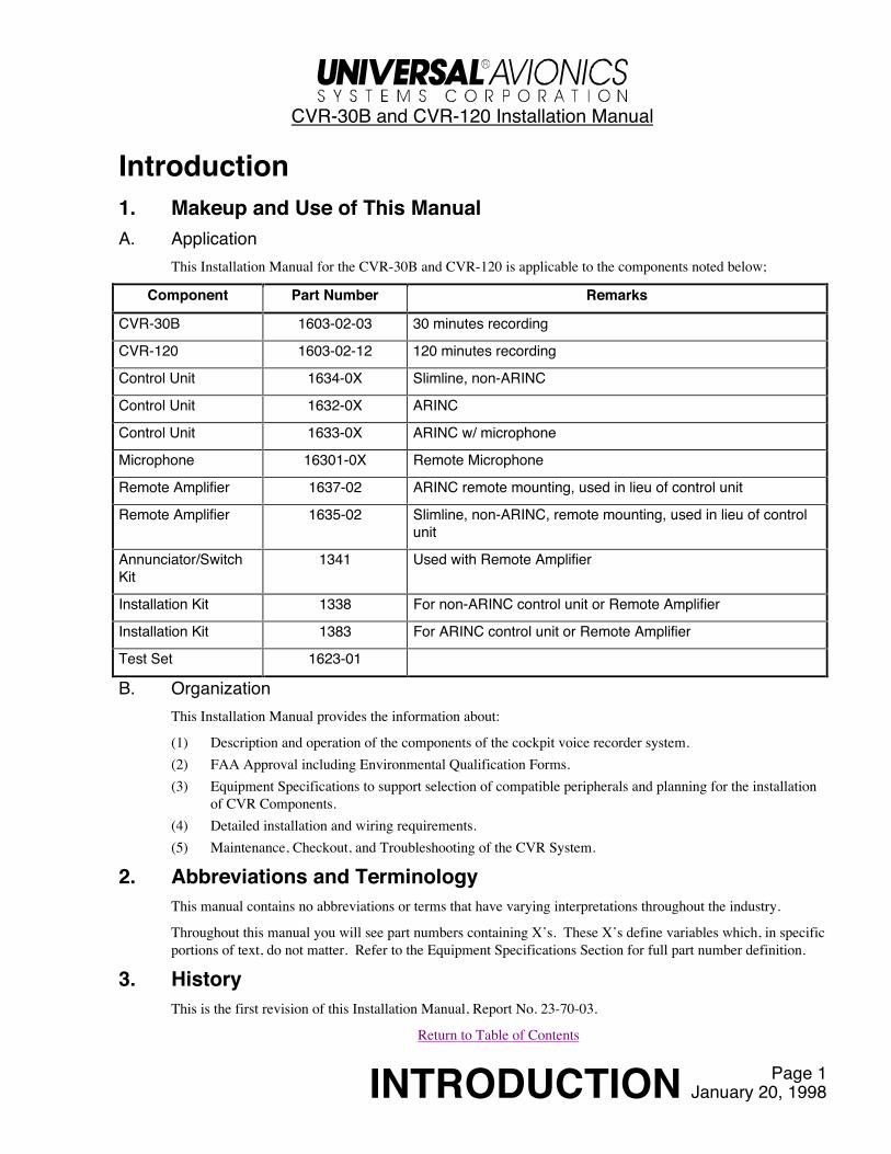
This Installation Manual for the CVR-30B and CVR-120 is applicable to the components noted below;
Component Part Number Remarks
CVR-30B 1603-02-03 30 minutes recording
CVR-120 1603-02-12 120 minutes recording
Control Unit 1634-0X Slimline, non-ARINC
Control Unit 1632-0X ARINC
Control Unit 1633-0X ARINC w/ microphone
Microphone 16301-0X Remote Microphone
Remote Amplifier 1637-02 ARINC remote mounting, used in lieu of control unit
Remote Amplifier 1635-02 Slimline, non-ARINC, remote mounting, used in lieu of controlunit
Annunciator/SwitchKit
1341 Used with Remote Amplifier
Installation Kit 1338 For non-ARINC control unit or Remote Amplifier
Installation Kit 1383 For ARINC control unit or Remote Amplifier
Test Set 1623-01
B. OrganizationThis Installation Manual provides the information about:
(1) Description and operation of the components of the cockpit voice recorder system.(2) FAA Approval including Environmental Qualification Forms.(3) Equipment Specifications to support selection of compatible peripherals and planning for the installation
of CVR Components.(4) Detailed installation and wiring requirements.(5) Maintenance, Checkout, and Troubleshooting of the CVR System.
2. Abbreviations and TerminologyThis manual contains no abbreviations or terms that have varying interpretations throughout the industry.
Throughout this manual you will see part numbers containing X’s. These X’s define variables which, in specificportions of text, do not matter. Refer to the Equipment Specifications Section for full part number definition.
3. HistoryThis is the first revision of this Installation Manual, Report No. 23-70-03.
Return to Table of Contents
CVR-30B and CVR-120 Installation Manual
Page 123-70-03 January 20, 1998
Description and Operation1. Description
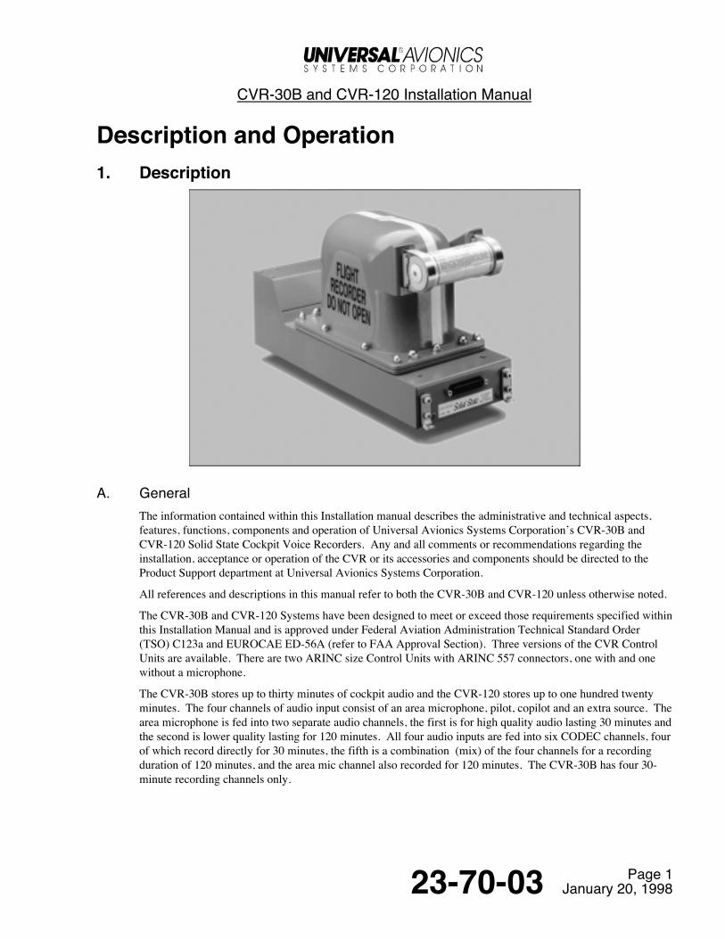
A. GeneralThe information contained within this Installation manual describes the administrative and technical aspects,features, functions, components and operation of Universal Avionics Systems Corporation’s CVR-30B andCVR-120 Solid State Cockpit Voice Recorders. Any and all comments or recommendations regarding theinstallation, acceptance or operation of the CVR or its accessories and components should be directed to theProduct Support department at Universal Avionics Systems Corporation.
All references and descriptions in this manual refer to both the CVR-30B and CVR-120 unless otherwise noted.
The CVR-30B and CVR-120 Systems have been designed to meet or exceed those requirements specified withinthis Installation Manual and is approved under Federal Aviation Administration Technical Standard Order(TSO) C123a and EUROCAE ED-56A (refer to FAA Approval Section). Three versions of the CVR ControlUnits are available. There are two ARINC size Control Units with ARINC 557 connectors, one with and onewithout a microphone.
The CVR-30B stores up to thirty minutes of cockpit audio and the CVR-120 stores up to one hundred twentyminutes. The four channels of audio input consist of an area microphone, pilot, copilot and an extra source. Thearea microphone is fed into two separate audio channels, the first is for high quality audio lasting 30 minutes andthe second is lower quality lasting for 120 minutes. All four audio inputs are fed into six CODEC channels, fourof which record directly for 30 minutes, the fifth is a combination (mix) of the four channels for a recordingduration of 120 minutes, and the area mic channel also recorded for 120 minutes. The CVR-30B has four 30-minute recording channels only.

CVR-30B and CVR-120 Installation Manual
Page 223-70-03 January 20, 1998
In addition to storing cockpit audio, the CVR is also capable of storing other data such as;
• Greenwich Mean Time (GMT) from an ARINC 429 bus
• GMT from a Frequency Shift Keying (FSK) signaling source
• Rotor speed for helicopter applications
• CVR internal BITE status
This data is synchronized with the audio during recording and playback.
The digital approach to a CVR is made possible by two key new technologies: 1) Adaptive Differential PulseCode Modulation (ADPCM) Digital Signal Processing (DSP) hardware and 2) flash memory. The ADPCMprocessor is a hardware engine that compresses and expands digital audio data. A compression of 4:1 is used inthe CVR and provides sufficient audio performance to meet existing and proposed MOPS (Minimum OperatingPerformance Standards). Flash memory is a type of Electrically Erasable Programmable Read Only Memory(EEPROM) which is characterized by fast write timing, high bit density, a high number of erase/write cycles,and data retention at high temperature with no backup power required.
The reliability of flash (EEPROM) memory is inherently very high, the memory cell structure of EEPROMs andPROMs are similar, with the added ability to electrically erase the EEPROMs. The normal operatingprocedures for writing and erasing EEPROMs is also inherently reliable and redundant. To write to a location inthe flash device, three operations are performed, 1) the old data is erased, 2) the data is written, and 3) the data isverified.
The operation of the CVR is controlled by a microprocessor operating at 24 MHz. The microprocessor isclosely coupled to a 68 M-byte flash memory array and performs the memory programming functions. Whenthe CVR is in the record mode, the compressed ADPCM data is read from a hardware interface and stored in theflash memory using special programming algorithms. The process is reversed for the play mode. All othercontrol functions such as self test and bulk erase are performed by the microprocessor.
CVR HARDWARE BLOCK DIAGRAM
CVR-30B and CVR-120 Installation Manual
Page 323-70-03 January 20, 1998
The CVR-30B and CVR-120 are line replaceable units (LRU) and are ARINC 757/557 compatible. Anunderwater locator beacon (ULB) is mounted on the front. Three models of panel-mounted control units areoffered, plus a remote preamp option.
B. Standard Features• TSO-C123a (ED-56A)
• Solid-State Flash Memory Array
• Input Recording
• 5 external source inputs
• 7 recorded channels (6 voice plus rotor speed)
• Records GMT
• Maintenance on Condition Only (excluding ULB)
• No Overhaul Required
• 30,000 hrs. MTBF
• Diagnostics and Maintenance Alert through Cockpit Control Panel
• Three Year Warranty
• Weighs: 30B = 13.0 lbs. & 120 = 13.0 lbs.
• Complete Onboard Aircraft Testing with Portable Test Set
• Direct replacement for ARINC 557 Analog Tape Units
• ARINC 757 compatible
C. Error DetectionCVR errors are detected at three possible times; during power up, during self test and during normal operation.Detected errors are reported via the CVR control unit FAIL Light. Errors are classified as either non-significant(some audio is recorded) or significant (high probability that no audio is recorded).
During power up, significant failures only will be reported by steady illumination of the red FAIL light on theCVR control unit. This FAIL Light can be cleared by pressing the SELF TEST button on the control unit ifthere is no longer an error. A self test should be performed following the report of a significant error to confirmthat the error is in fact significant.
During the on demand self test, an inspection of a memory array verify error count is performed, if the errorcount is greater than the allowed tolerance, a flash (or steady) code will be displayed on the red FAIL Light onthe CVR control unit.
D. Recorder UnitThe Recorder Unit contains the Recorder Assembly and associated electronics. The enclosure is InternationalOrange to meet requirements of the National Transportation Safety Board (NTSB). An Underwater LocatorBeacon (ULB) is attached as required by regulations. The Recorder Unit mounts in an ARINC 404A 1/2 ATRshort rack (Kit 1338 or 1383).

CVR-30B and CVR-120 Installation Manual
Page 423-70-03 January 20, 1998
E. Control UnitThe Control Unit (P/N 1632-0X, 1633-0X or 1634-0X) contains an amplifier for the Area Microphone, ERASEPush Button, TEST Push Button, PASS and FAIL Annunciators, SIGNAL LEVEL Indicator and aHEADPHONE Jack. The panel mounted Control Unit mounts with standard DZUS fasteners. The ControlUnit is available in either black or gray and will operate with either 5 VDC or 28 VDC lighting. Control UnitP/N 1633-0X has a built in microphone.
SLIMLINE CONTROL UNIT, P/N 1634-0X
SIGNAL LEVEL
HEADPHONE TEST
PASS FAIL
ERASE
UNIVERSAL
ARINC CONTROL UNIT, P/N 1632-0X
ARINC CONTROL UNIT, P/N 1633-0X
CVR-30B and CVR-120 Installation Manual
Page 523-70-03 January 20, 1998
F. Remote Mic AmplifierThe Remote Mic Amplifier (P/N 1635-02 or 1637-02) and the Annunciator/Switch Kit (P/N 1341) are used inlieu of the Control Unit when there is not enough space in the cockpit for the panel mounted Control Unit.Refer to Annunciator/Switch Kit below.
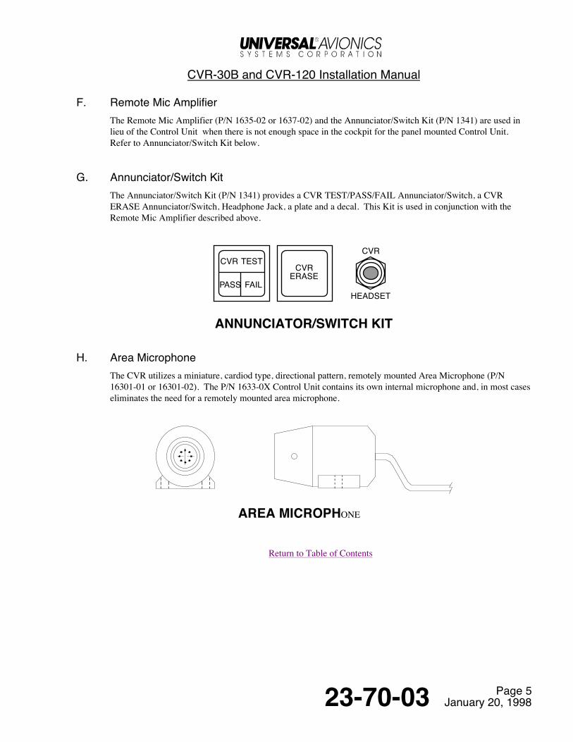
G. Annunciator/Switch KitThe Annunciator/Switch Kit (P/N 1341) provides a CVR TEST/PASS/FAIL Annunciator/Switch, a CVRERASE Annunciator/Switch, Headphone Jack, a plate and a decal. This Kit is used in conjunction with theRemote Mic Amplifier described above.
CVR TEST
PASS FAIL
CVRERASE
CVR
HEADSET
ANNUNCIATOR/SWITCH KIT
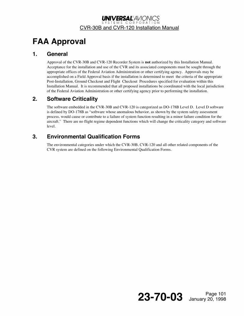
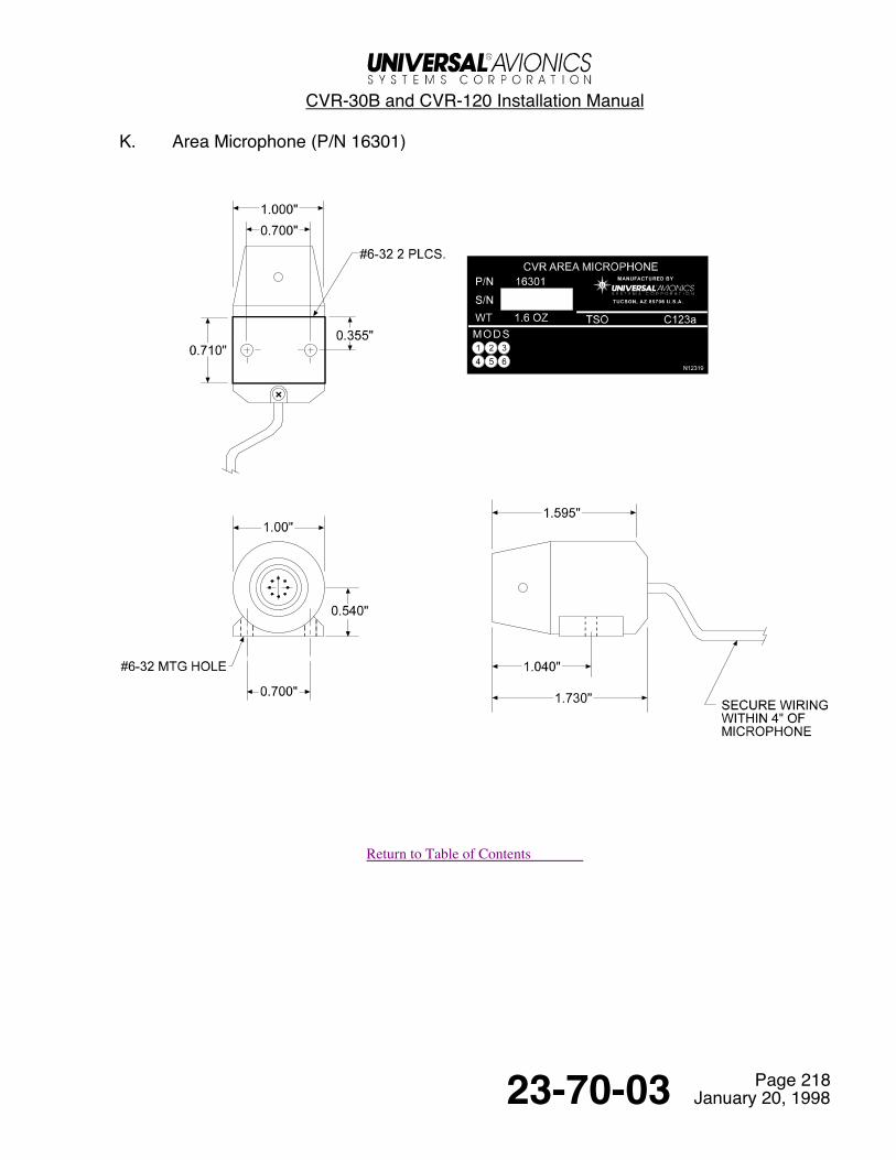
H. Area MicrophoneThe CVR utilizes a miniature, cardiod type, directional pattern, remotely mounted Area Microphone (P/N16301-01 or 16301-02). The P/N 1633-0X Control Unit contains its own internal microphone and, in most caseseliminates the need for a remotely mounted area microphone.
AREA MICROPHONE
Return to Table of Contents
CVR-30B and CVR-120 Installation Manual
Page 10123-70-03 January 20, 1998
FAA Approval1. General
Approval of the CVR-30B and CVR-120 Recorder System is not authorized by this Installation Manual.Acceptance for the installation and use of the CVR and its associated components must be sought through theappropriate offices of the Federal Aviation Administration or other certifying agency. Approvals may beaccomplished on a Field Approval basis if the installation is determined to meet the criteria of the appropriatePost-Installation, Ground Checkout and Flight Checkout Procedures specified for evaluation within thisInstallation Manual. It is recommended that all proposed installations be coordinated with the local jurisdictionof the Federal Aviation Administration or other certifying agency prior to performing the installation.
2. Software CriticalityThe software embedded in the CVR-30B and CVR-120 is categorized as DO-178B Level D. Level D softwareis defined by DO-178B as “software whose anomalous behavior, as shown by the system safety assessmentprocess, would cause or contribute to a failure of system function resulting in a minor failure condition for theaircraft.” There are no flight regime dependent functions which will change the criticality category and softwarelevel.
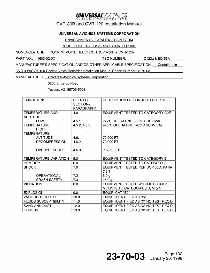
3. Environmental Qualification FormsThe environmental categories under which the CVR-30B, CVR-120 and all other related components of theCVR system are defined on the following Environmental Qualification Forms.
CVR-30B and CVR-120 Installation Manual
Page 10223-70-03 January 20, 1998
UNIVERSAL AVIONICS SYSTEMS CORPORATION
ENVIRONMENTAL QUALIFICATION FORM
PROCEDURE TSO C123 AND RTCA DO-160C
NOMENCLATURE: COCKPIT VOICE RECORDER (CVR-30B & CVR-120)
PART NO.: 1603-02-0X TSO NUMBER: C123a & ED-56A
MANUFACTURER’S SPECIFICATION AND/OR OTHER APPLICABLE SPECIFICATION: Contained in
CVR-30B/CVR-120 Cockpit Voice Recorder Installation Manual Report Number 23-70-03
MANUFACTURER: Universal Avionics Systems Corporation
3260 E. Lerdo Road
Tucson, AZ. 85706-5021
CONDITIONS DO-160CSECTION#PARAGRAPH#
DESCRIPTION OF CONDUCTED TESTS
TEMPERATURE ANDALTITUDE
4.0 EQUIPMENT TESTED TO CATEGORY C2E1
LOWTEMPERATURE
HIGHTEMPERATURE
4.5.14.5.2, 4.5.3
-55°C OPERATING, -55°C SURVIVAL+70°C OPERATING, +85°C SURVIVAL
ALTITUDE 4.6.1 70,000 FTDECOMPRESSION 4.6.2 70,000 FT
OVERPRESSURE 4.6.3 -15,000 FT
TEMPERATURE VARIATION 5.0 EQUIPMENT TESTED TO CATEGORY BHUMIDITY 6.0 EQUIPMENT TESTED TO CATEGORY ASHOCK 7.0 EQUIPMENT TESTED PER DO-160C, PARA
7.2.1OPERATIONALCRASH SAFETY
7.27.3
6.0 g15.0 g
VIBRATION 8.0 EQUIPMENT TESTED WITHOUT SHOCKMOUNTS TO CATEGORIES B, M & N
EXPLOSION 9.0 EQUIP. CAT "E2"WATERPROOFNESS 10.0 EQUIP. IDENTIFIED AS "W"FLUIDS SUSCEPTIBILITY 11.0 EQUIP. IDENTIFIED AS "X" NO TEST REQ'DSAND AND DUST 12.0 EQUIP. IDENTIFIED AS "X" NO TEST REQ'DFUNGUS 13.0 EQUIP. IDENTIFIED AS "X" NO TEST REQ'D

CVR-30B and CVR-120 Installation Manual
Page 10323-70-03 January 20, 1998
UASC ENVIRONMENTAL QUALIFICATION FORM (cont.)
NOMENCLATURE: COCKPIT VOICE RECORDER (CVR-30B & CVR-120)
PART NO.: 1603-02-0X
CONDITIONS DO-160CSECTION#PARAGRAPH#
DESCRIPTION OF CONDUCTED TESTS
SALT SPRAY 14.0 EQUIP. IDENTIFIED AS "X" NO TEST REQ’DMAGNETIC EFFECT 15.0 EQUIPMENT IDENTIFIED AS CLASS "Z"POWER INPUT 16.0 EQUIPMENT TESTED TO CATEGORY "Z"VOLTAGE SPIKECONDUCTED
17.0 EQUIPMENT TESTED TO CATEGORY "A"
AUDIO FREQUENCYSUSCEPTIBILITY
18.0 EQUIPMENT TESTED TO CATEGORY "Z"
INDUCED SIGNALSUSCEPTIBILITY
19.0 EQUIPMENT TESTED TO CATEGORY "Z"
RADIO FREQUENCYSUSCEPTIBILITY
20.0 EQUIPMENT TESTED TO CATEGORY "T"
RADIO FREQUENCYEMISSION
21.0 EQUIPMENT TESTED TO CATEGORY "Z"
LIGHTNING INDUCEDTRANS SUS
22.0 EQUIPMENT TESTED TO CATEGORY A3E3
LIGHTNING DIRECTEFFECTS
23.0 EQUIP. IDENTIFIED AS "X" NO TEST REQ’D
ICING 24.0 EQUIP. IDENTIFIED AS "X" NO TEST REQ’DCRASH SURVIVABILITY ACCORDING TO TSO C-123 & ED-55, 7.1

CVR-30B and CVR-120 Installation Manual
Page 10423-70-03 January 20, 1998
UNIVERSAL AVIONICS SYSTEMS CORPORATION
ENVIRONMENTAL QUALIFICATION FORM
PROCEDURE TSO C123 AND RTCA DO-160C
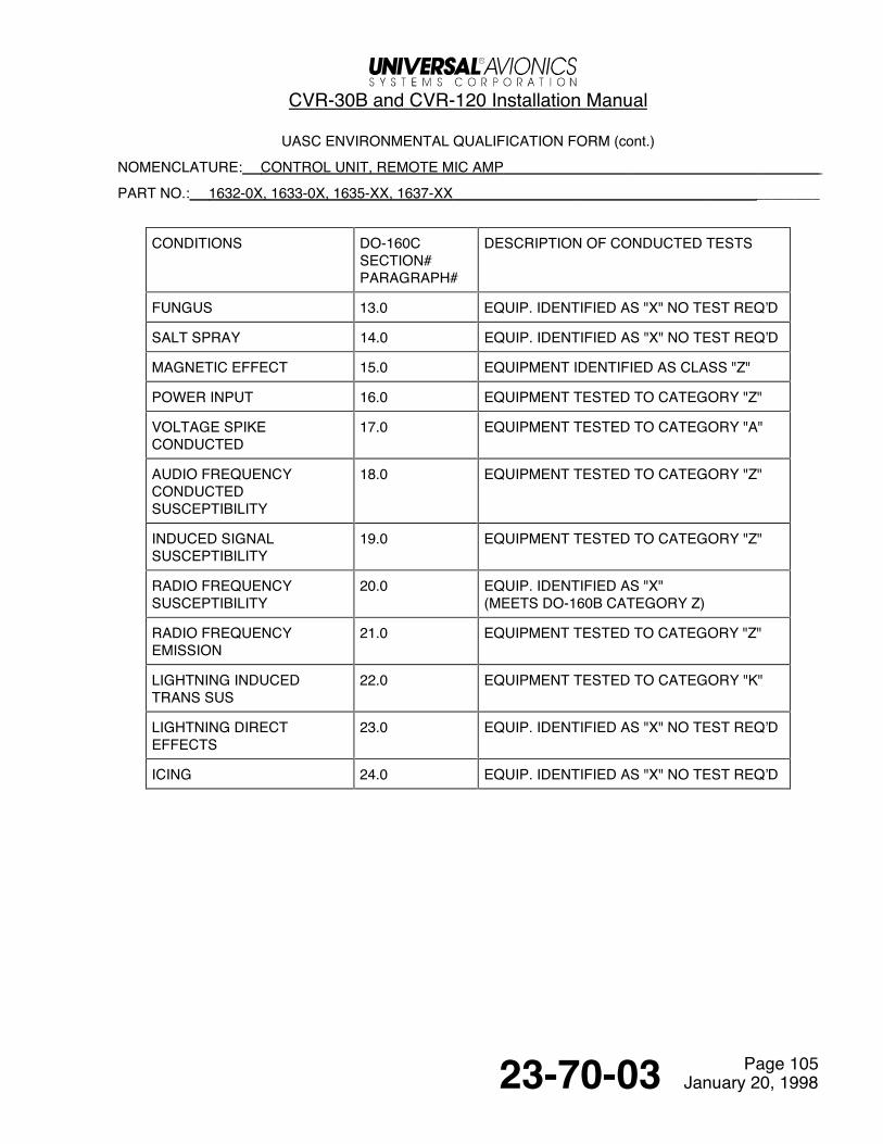
NOMENCLATURE: CONTROL UNIT, REMOTE MIC AMP
PART NO.: 1632-0X, 1633-0X, 1635-XX, 1637-XX________ TSO NUMBER: C123a & ED-56A
MANUFACTURER’S SPECIFICATION AND/OR OTHER APPLICABLE SPECIFICATION: Contained in
CVR-30B/CVR-120 Cockpit Voice Recorder Installation Manual Report Number 23-70-03
MANUFACTURER: Universal Avionics Systems Corporation
3260 E. Lerdo Road
Tucson, AZ. 85706-5021
CONDITIONS DO-160CSECTION#PARAGRAPH#
DESCRIPTION OF CONDUCTED TESTS
TEMPERATURE ANDALTITUDE
4.0 CONTROL UNIT & REMOTE MIC AMPLIFIERTESTED TO CATEGORY A2MICROPHONE TESTED TO CATEGORY A2
LOW TEMPERATUREHIGH TEMPERATURE
4.5.14.5.2, 4.5.3
-55°C OPERATING, -55°C SURVIVAL+70°C OPERATING, +85°C SURVIVAL
ALTITUDE *2 4.6.1 70,000 FTDECOMPRESSION *2 4.6.2 70,000 FTOVERPRESSURE *2 4.6.3 -15,000 FT
TEMPERATURE VARIATION 5.3 EQUIPMENT TESTED TO CATEGORY B
HUMIDITY *2 6.0 EQUIPMENT TESTED TO CATEGORY A50°C, 95%, 48 HOURS
SHOCK 7.0 EQUIPMENT TESTED PER DO-160C
OPERATIONALCRASH SAFETY
7.27.3
6.0 g15.0 g
VIBRATION 8.0 EQUIPMENT TESTED WITHOUT SHOCKMOUNTS TO CATEGORIES B, M & N
EXPLOSION 9.0 of (DO-160C) EQUIP. CAT "X" INTRINSICALLY SAFE
WATERPROOFNESS 10.0 EQUIP. IDENTIFIED AS "X" NO TEST REQ'D
FLUIDS SUSCEPTIBILITY 11.0 EQUIP. IDENTIFIED AS "X" NO TEST REQ'D
SAND AND DUST 12.0 EQUIP. IDENTIFIED AS "X" NO TEST REQ'D
See Temporary Change 23.70.03-3


CVR-30B and CVR-120 Installation Manual
Page 10523-70-03 January 20, 1998
UASC ENVIRONMENTAL QUALIFICATION FORM (cont.)
NOMENCLATURE: CONTROL UNIT, REMOTE MIC AMP
PART NO.: 1632-0X, 1633-0X, 1635-XX, 1637-XX ________
CONDITIONS DO-160CSECTION#PARAGRAPH#
DESCRIPTION OF CONDUCTED TESTS
FUNGUS 13.0 EQUIP. IDENTIFIED AS "X" NO TEST REQ’D
SALT SPRAY 14.0 EQUIP. IDENTIFIED AS "X" NO TEST REQ’D
MAGNETIC EFFECT 15.0 EQUIPMENT IDENTIFIED AS CLASS "Z"
POWER INPUT 16.0 EQUIPMENT TESTED TO CATEGORY "Z"
VOLTAGE SPIKECONDUCTED
17.0 EQUIPMENT TESTED TO CATEGORY "A"
AUDIO FREQUENCYCONDUCTEDSUSCEPTIBILITY
18.0 EQUIPMENT TESTED TO CATEGORY "Z"
INDUCED SIGNALSUSCEPTIBILITY
19.0 EQUIPMENT TESTED TO CATEGORY "Z"
RADIO FREQUENCYSUSCEPTIBILITY
20.0 EQUIP. IDENTIFIED AS "X"(MEETS DO-160B CATEGORY Z)
RADIO FREQUENCYEMISSION
21.0 EQUIPMENT TESTED TO CATEGORY "Z"
LIGHTNING INDUCEDTRANS SUS
22.0 EQUIPMENT TESTED TO CATEGORY "K"
LIGHTNING DIRECTEFFECTS
23.0 EQUIP. IDENTIFIED AS "X" NO TEST REQ’D
ICING 24.0 EQUIP. IDENTIFIED AS "X" NO TEST REQ’D
CVR-30B and CVR-120 Installation Manual
Page 10623-70-03 January 20, 1998
UNIVERSAL AVIONICS SYSTEMS CORPORATION
ENVIRONMENTAL QUALIFICATION FORM
PROCEDURE TSO C123 AND RTCA DO-160C
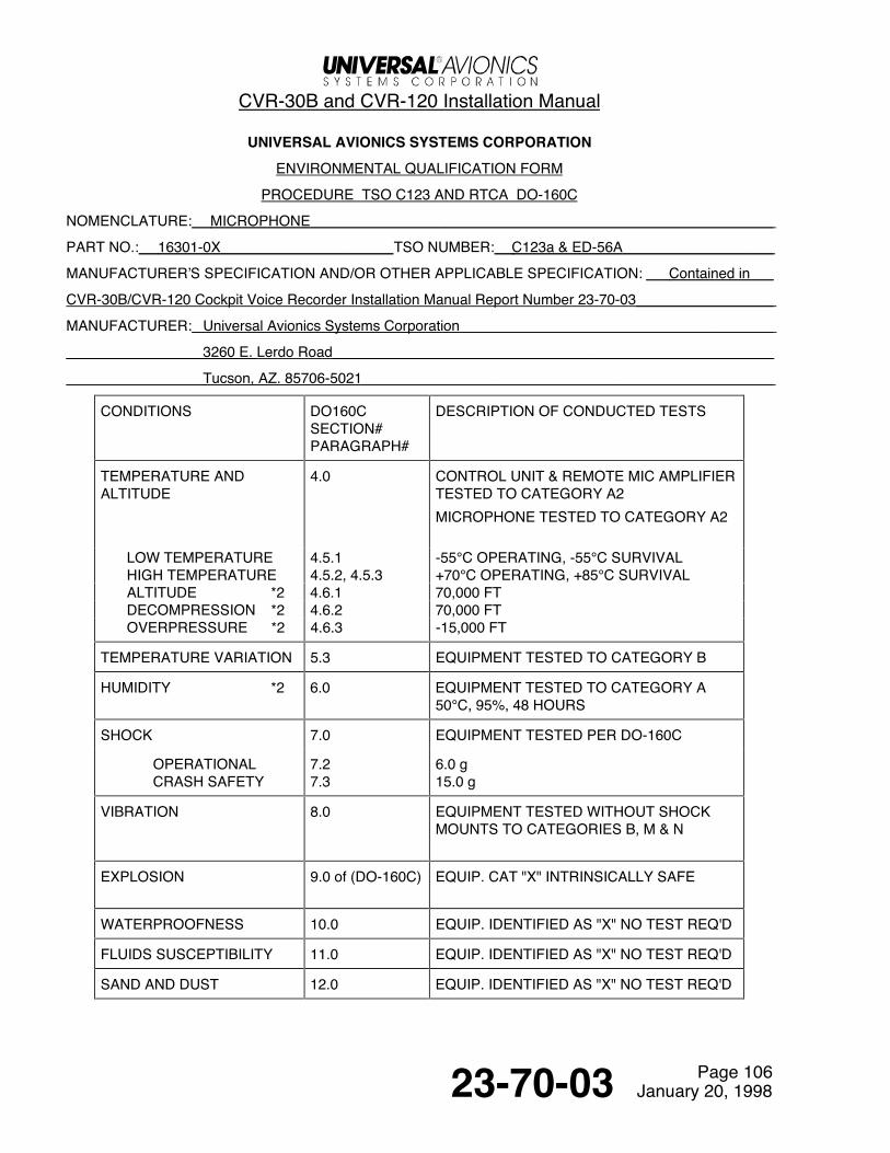
NOMENCLATURE: MICROPHONE
PART NO.: 16301-0X TSO NUMBER: C123a & ED-56A
MANUFACTURER’S SPECIFICATION AND/OR OTHER APPLICABLE SPECIFICATION: Contained in
CVR-30B/CVR-120 Cockpit Voice Recorder Installation Manual Report Number 23-70-03
MANUFACTURER: Universal Avionics Systems Corporation
3260 E. Lerdo Road
Tucson, AZ. 85706-5021
CONDITIONS DO160CSECTION#PARAGRAPH#
DESCRIPTION OF CONDUCTED TESTS
TEMPERATURE ANDALTITUDE
4.0 CONTROL UNIT & REMOTE MIC AMPLIFIERTESTED TO CATEGORY A2MICROPHONE TESTED TO CATEGORY A2
LOW TEMPERATUREHIGH TEMPERATURE
4.5.14.5.2, 4.5.3
-55°C OPERATING, -55°C SURVIVAL+70°C OPERATING, +85°C SURVIVAL
ALTITUDE *2 4.6.1 70,000 FTDECOMPRESSION *2 4.6.2 70,000 FTOVERPRESSURE *2 4.6.3 -15,000 FT
TEMPERATURE VARIATION 5.3 EQUIPMENT TESTED TO CATEGORY B
HUMIDITY *2 6.0 EQUIPMENT TESTED TO CATEGORY A50°C, 95%, 48 HOURS
SHOCK 7.0 EQUIPMENT TESTED PER DO-160C
OPERATIONALCRASH SAFETY
7.27.3
6.0 g15.0 g
VIBRATION 8.0 EQUIPMENT TESTED WITHOUT SHOCKMOUNTS TO CATEGORIES B, M & N
EXPLOSION 9.0 of (DO-160C) EQUIP. CAT "X" INTRINSICALLY SAFE
WATERPROOFNESS 10.0 EQUIP. IDENTIFIED AS "X" NO TEST REQ'D
FLUIDS SUSCEPTIBILITY 11.0 EQUIP. IDENTIFIED AS "X" NO TEST REQ'D
SAND AND DUST 12.0 EQUIP. IDENTIFIED AS "X" NO TEST REQ'D

CVR-30B and CVR-120 Installation Manual
Page 10723-70-03 January 20, 1998
UASC ENVIRONMENTAL QUALIFICATION FORM (cont.)
NOMENCLATURE: MICROPHONE
PART NO.: 16301-0X________
CONDITIONS DO160CSECTION#PARAGRAPH#
DESCRIPTION OF CONDUCTED TESTS
FUNGUS 13.0 EQUIP. IDENTIFIED AS "X" NO TEST REQ’D
SALT SPRAY 14.0 EQUIP. IDENTIFIED AS "X" NO TEST REQ’D
MAGNETIC EFFECT 15.0 EQUIPMENT IDENTIFIED AS CLASS "Z"
POWER INPUT 16.0 EQUIP. IDENTIFIED AS "X" NO TEST REQ’D
VOLTAGE SPIKECONDUCTED
17.0 EQUIP. IDENTIFIED AS "X" NO TEST REQ’D
AUDIO FREQUENCYCONDUCTEDSUSCEPTIBILITY
18.0 EQUIP. IDENTIFIED AS "X" NO TEST REQ’D
INDUCED SIGNALSUSCEPTIBILITY
19.0 EQUIP. IDENTIFIED AS "X" NO TEST REQ’D
RADIO FREQUENCYSUSCEPTIBILITY
20.0 EQUIP. IDENTIFIED AS "X" NO TEST REQ’D
RADIO FREQUENCYEMISSION
21.0 EQUIPMENT TESTED TO CATEGORY "Z"
LIGHTNING INDUCEDTRANS SUS
22.0 EQUIPMENT TESTED TO CATEGORY "K"
LIGHTNING DIRECTEFFECTS
23.0 EQUIP. IDENTIFIED AS "X" NO TEST REQ’D
ICING 24.0 EQUIP. IDENTIFIED AS "X" NO TEST REQ’D

CVR-30B and CVR-120 Installation Manual
Page 10823-70-03 January 20, 1998
4. Airplane Flight Manual SupplementSupplementing the Airplane Flight Manual with CVR Operating instructions can be accomplished severaldifferent ways.
One method of preparing an AFMS is to include all operational instructions in one supplement.
Another method is to merely have a supplement referring to Universal’s Operational Instructions. TheseOperational instructions as well as the supplement would both go into the Supplements Section of the AirplaneFlight Manual.
Some local certifying agencies differ on the method of supplementing, so it would be a good idea to check withthem first.
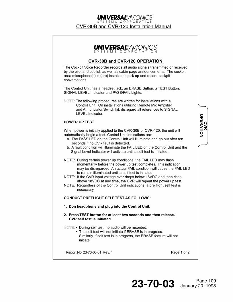
5. CVR Operating InstructionsThe following CVR operating instructions are provided for insertion into the Supplements Section of theAirplane Flight Manual if so desired. Permission is hereby granted to reproduce these instructions.
These instructions are also available from Universal Avionics Systems Corporation upon request. Ask forOperating Instructions, Report No. 23-70-03.01
See Temporary Change 23.70.03-2

CVR-30B and CVR-120 Installation Manual
Page 10923-70-03 January 20, 1998

CVR-30B and CVR-120 Installation Manual
Page 11023-70-03 January 20, 1998
Return to Table of Contents

CVR-30B and CVR-120 Installation Manual
Page 20123-70-03 January 20, 1998
Equipment Specifications1. Equipment IdentificationA. CVR-30B and CVR-120
B. Control Unit
C. Remote Mic Amplifier - ARINC
D. Remote Mic Amplifier - Slimline
E. Area Microphone

CVR-30B and CVR-120 Installation Manual
Page 20223-70-03 January 20, 1998
2. Equipment Specification TablesA. Recorder Unit (P/N 1603-02-30 or 1603-02-12)
Characteristic Specification
Height 6.78”
Width 4.875”
Length 12.56”
Weight 13.0 lbs.
Power Input 28 VDC or 115 VAC
Power Consumption Approx 14W nominal @ 27.5 VDCApprox 18W nominal @ 115 VAC
Inputs 3 crew microphones1 area microphoneRotor speedGMT (ARINC 429 or FSK)OMS (Onboard Maintenance System)Data Link (future)
Medium Solid State Flash Memory array
Erase Fail Safe; double electrical interlock
Recorded Audio Frequency Response Crew microphones 150 to 3500 HzArea microphone 150 to 6000 Hz
Analog Rotor Speed Input 10 to 15,000 Hz rotor tach frequency200 K Ohms Impedance.2 volts min., 100 volts max.
Headphone Output (Monitor) 600 Ohms, 10 mw
Audio Input Impedance 5000 Ohms, each channel
Recorded SNR 48 dB (Area microphone)45 dB (minimum)
Harmonic Distortion 10% max THD and noise at 0 dB input6% max THD and noise at -20 dB input6.3% max THD for area microphone
Audio Outputs (6 channels) 775 mV RMS into 600 Ohms (with 330 VRMS input)
Underwater Locator Beacon Battery Life 6 years (Dukane Model DK120, replaceable battery)
Mounting Solid Rack Mount (shock mounting is not required in aircraftor helicopters)
CVR-30B and CVR-120 Installation Manual
Page 20323-70-03 January 20, 1998
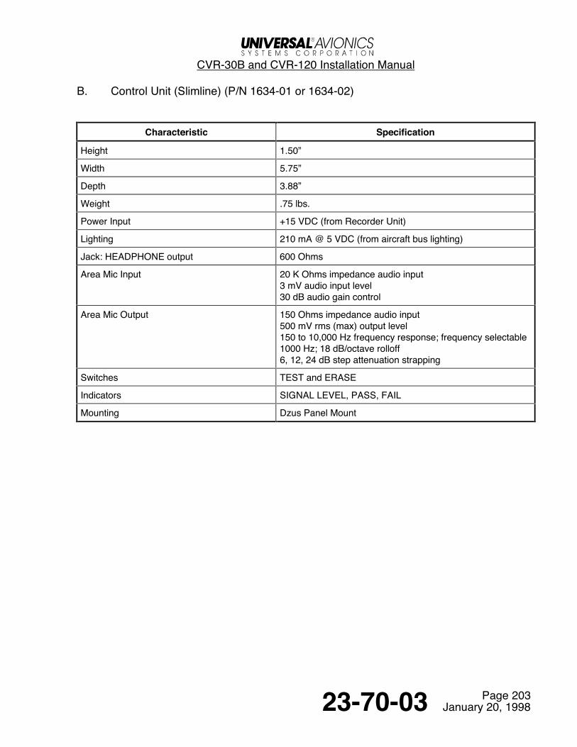
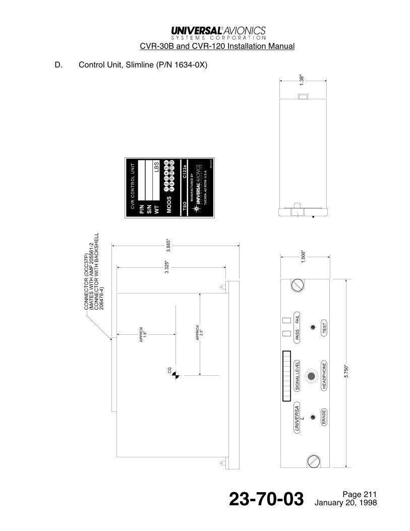
B. Control Unit (Slimline) (P/N 1634-01 or 1634-02)
Characteristic Specification
Height 1.50”
Width 5.75”
Depth 3.88”
Weight .75 lbs.
Power Input +15 VDC (from Recorder Unit)
Lighting 210 mA @ 5 VDC (from aircraft bus lighting)
Jack: HEADPHONE output 600 Ohms
Area Mic Input 20 K Ohms impedance audio input3 mV audio input level30 dB audio gain control
Area Mic Output 150 Ohms impedance audio input500 mV rms (max) output level150 to 10,000 Hz frequency response; frequency selectable1000 Hz; 18 dB/octave rolloff6, 12, 24 dB step attenuation strapping
Switches TEST and ERASE
Indicators SIGNAL LEVEL, PASS, FAIL
Mounting Dzus Panel Mount

CVR-30B and CVR-120 Installation Manual
Page 20423-70-03 January 20, 1998
C. Control Unit (ARINC) (P/N 1632-01 or 1632-02)
Characteristic Specification
Height 2.25”
Width 5.75”
Depth 3.625”
Weight 0.9 lbs.
Power Input +15 VDC (from Recorder Unit)
Lighting 210 mA @ 5 VDC (from aircraft bus lighting)
Jack: HEADPHONE output 600 Ohms
Area Mic Input 20 K Ohms impedance audio input3 mV audio input level30 dB audio gain control
Area Mic Output 150 Ohms impedance audio input500 mV output level150 to 10,000 Hz frequency response; frequency selectable1000 Hz; 18 dB/octave rolloff1000 Hz; 18 dB/octave rolloff6, 12, 24 dB step attenuation strapping
Switches TEST and ERASE
Indicators SIGNAL LEVEL, PASS, FAIL
Mounting Dzus Panel Mount
CVR-30B and CVR-120 Installation Manual
Page 20523-70-03 January 20, 1998
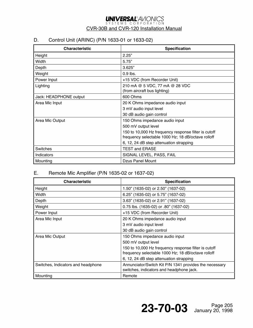
D. Control Unit (ARINC) (P/N 1633-01 or 1633-02)Characteristic Specification
Height 2.25”Width 5.75”Depth 3.625”Weight 0.9 lbs.Power Input +15 VDC (from Recorder Unit)Lighting 210 mA @ 5 VDC, 77 mA @ 28 VDC
(from aircraft bus lighting)Jack: HEADPHONE output 600 OhmsArea Mic Input 20 K Ohms impedance audio input
3 mV audio input level30 dB audio gain control
Area Mic Output 150 Ohms impedance audio input500 mV output level150 to 10,000 Hz frequency response filter is cutofffrequency selectable 1000 Hz; 18 dB/octave rolloff6, 12, 24 dB step attenuation strapping
Switches TEST and ERASEIndicators SIGNAL LEVEL, PASS, FAILMounting Dzus Panel Mount
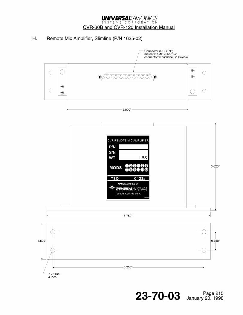
E. Remote Mic Amplifier (P/N 1635-02 or 1637-02)Characteristic Specification
Height 1.50” (1635-02) or 2.50” (1637-02)Width 6.25” (1635-02) or 5.75” (1637-02)Depth 3.63” (1635-02) or 2.91” (1637-02)Weight 0.75 lbs. (1635-02) or .80” (1637-02)Power Input +15 VDC (from Recorder Unit)Area Mic Input 20 K Ohms impedance audio input
3 mV audio input level30 dB audio gain control
Area Mic Output 150 Ohms impedance audio input500 mV output level150 to 10,000 Hz frequency response filter is cutofffrequency selectable 1000 Hz; 18 dB/octave rolloff6, 12, 24 dB step attenuation strapping
Switches, Indicators and headphone Annunciator/Switch Kit P/N 1341 provides the necessaryswitches, indicators and headphone jack.
Mounting Remote

CVR-30B and CVR-120 Installation Manual
Page 20623-70-03 January 20, 1998
3. Installation KitsA. CVR Installation Kit - CVR and Slimline Control Unit or Slimline Remote Mic
Amplifier (P/N 1338)Kit No 1338 is used to install the CVR when either the Slimline Control Unit P/N 1634-0X or the SlimlineRemote Mic Amplifier P/N 1635-02 is used. If the Slimline Remote Mic Amplifier is used then the CVRRemote Switch and Jack Kit No 1341 should also be used.
Kit No. 1338 Consists of:
QTY P/N NAME
1 L404A-50-S-1/DPXB-0 1/2 ATR Short Rack
1 DPXBMA-57-33S-00 Rack Connector
1 205561-2 Controller/Remote Amp Connector
1 206478-4 Connector Backshell
1 91067-2 Insertion/Extraction Tool
B. CVR Installation Kit - CVR and ARINC Control Unit or ARINC Remote Mic Amplifier(P/N 1383)Kit No 1383 is used to install the CVR when either the ARINC Control Unit P/Ns 1632-XX or 1633-XX, or theARINC Remote Mic Amplifier P/N 1637-02 is used. If the ARINC Remote Mic Amplifier is used then theCVR Remote Switch and Jack Kit No 1341 should also be used.
Kit No. 1383 Consists of:
QTY P/N NAME
1 L404A-50-S-1/DPXB-0 1/2 ATR Short Rack
1 DPXBNA-57M-33S-00 Rack Connector
1 MS3126F20-41S Controller/Remote Mic Amp Connector

CVR-30B and CVR-120 Installation Manual
Page 20723-70-03 January 20, 1998
C. Remote Switch and Jack Installation Kit (P/N 1341)Kit No 1341 provides the necessary switches, annunciators and headphone jacks which are need when a RemoteMic Amplifier, P/N 1637-02 or 1635-02 is installed.
Kit No. 1341 Consists of:
QTY P/N NAME
1 95-18-11-E6-55631 Annunciator Switch “CVR TEST /PASS / FAIL”
1 95-18-11-H6-55632 Annunciator Switch “CVR ERASE”
1 39F652 Headphone Jack
1 1341-1 Annunciator Plate
1 L12304 Annunciator Plate Label

CVR-30B and CVR-120 Installation Manual
Page 20823-70-03 January 20, 1998
4. DrawingsA. CVR-30B/120 (P/N 1603-02-XX)
CVR-30B and CVR-120 Installation Manual
Page 20923-70-03 January 20, 1998
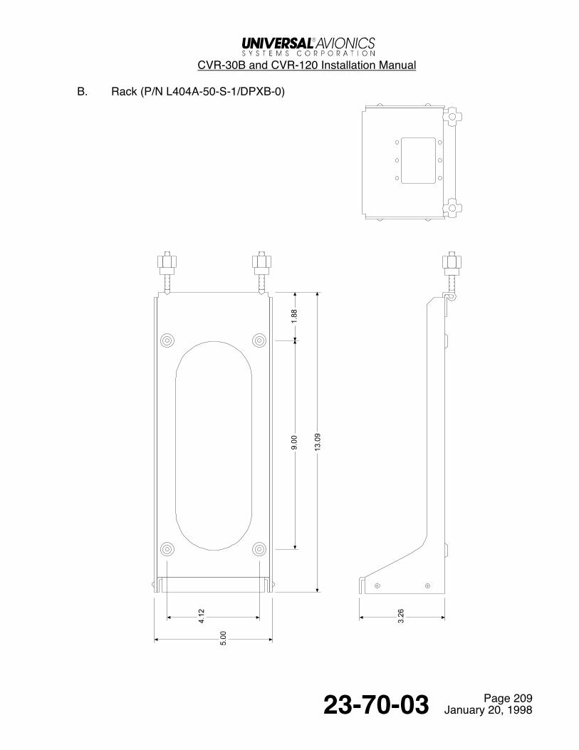
B. Rack (P/N L404A-50-S-1/DPXB-0)
CVR-30B and CVR-120 Installation Manual
Page 21023-70-03 January 20, 1998
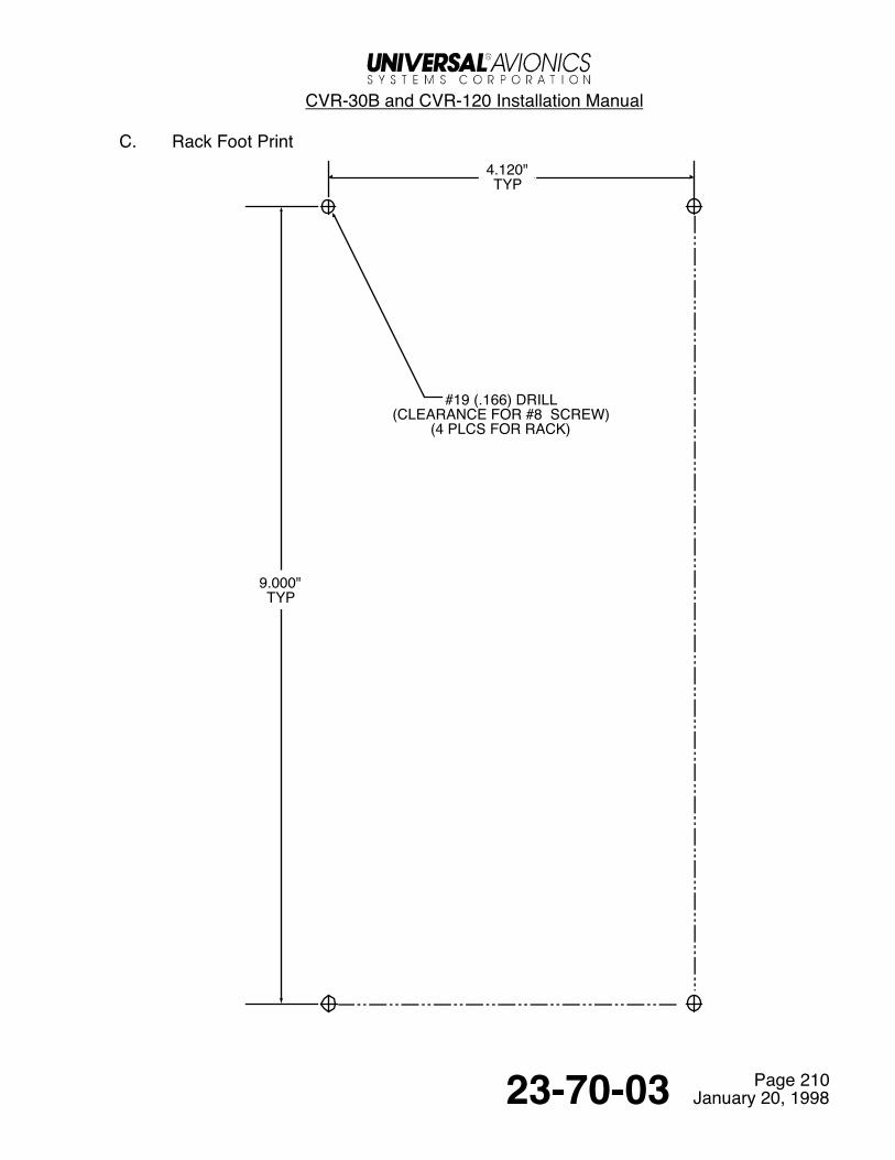
C. Rack Foot Print4.120"TYP
9.000"TYP
#19 (.166) DRILL(CLEARANCE FOR #8 SCREW)
(4 PLCS FOR RACK)
CVR-30B and CVR-120 Installation Manual
Page 21123-70-03 January 20, 1998
D. Control Unit, Slimline (P/N 1634-0X)

CVR-30B and CVR-120 Installation Manual
Page 21223-70-03 January 20, 1998
E. Control Unit, ARINC (P/N 1632-0X)

CVR-30B and CVR-120 Installation Manual
Page 21323-70-03 January 20, 1998
F. Control Unit, ARINC w/mic (P/N 1633-0X)

CVR-30B and CVR-120 Installation Manual
Page 21423-70-03 January 20, 1998
G. Remote Mic Amplifier (P/N 1637-02)
CVR-30B and CVR-120 Installation Manual
Page 21523-70-03 January 20, 1998
H. Remote Mic Amplifier, Slimline (P/N 1635-02)

CVR-30B and CVR-120 Installation Manual
Page 21623-70-03 January 20, 1998
I. Remote Switch and Jack Kit (P/N 1341)
1341-3 DECAL
CVR-30B and CVR-120 Installation Manual
Page 21723-70-03 January 20, 1998
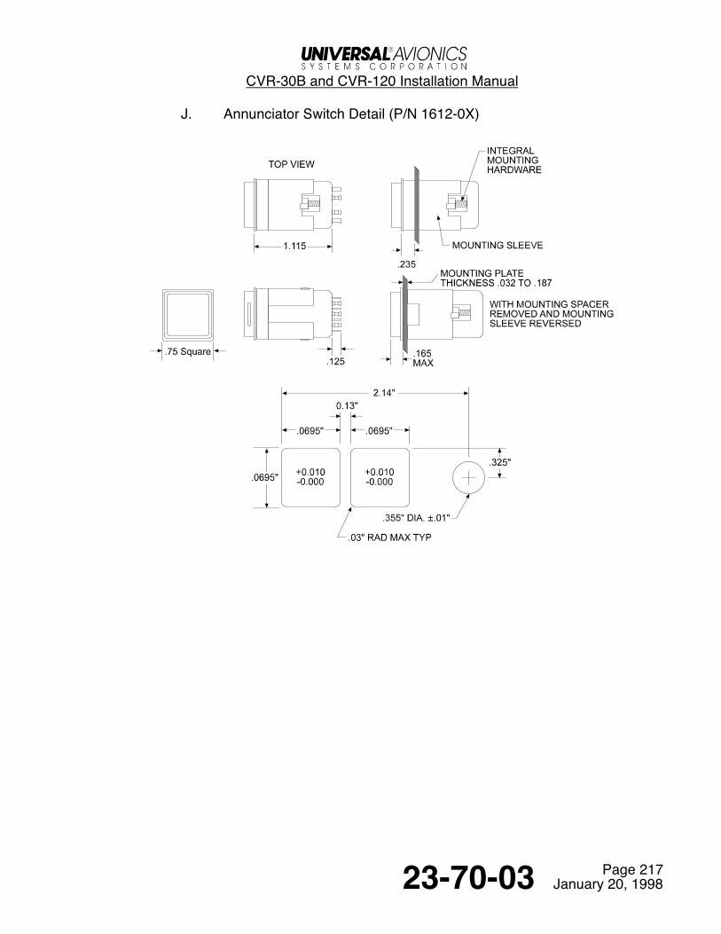
J. Annunciator Switch Detail (P/N 1612-0X)
CVR-30B and CVR-120 Installation Manual
Page 21823-70-03 January 20, 1998
K. Area Microphone (P/N 16301)
Return to Table of Contents
CVR-30B and CVR-120 Installation Manual
Page 30123-70-03 January 20, 1998
Installation and Wiring1. General
This section contains considerations and recommendations for installation of the Cockpit Voice Recorder andassociated system components. Interconnect harness wiring, physical mounting and Area Microphone must beconsidered as required to satisfy all applicable regulations. The conditions and tests required for TSO approvalof this article are minimum performance standards. It is the responsibility of those desiring to install this articleeither on or within a specific type or class of aircraft to determine that the aircraft installation conditions arewithin TSO standards. If not within TSO standards, the article may be installed only if the applicant documentsfurther evaluation for an acceptable installation and it is approved by the Administrator of the Federal AviationAdministration or other certifying agency.The Federal Aviation Administration has issued several Advisory Circulars which may be referred to in theapproval processes. Advisory Circular25.1457-1A specifically addresses one acceptable means of compliance with Federal Aviation Regulation (FAR)25.1457 (b), (e) and (f). Installations must conform to the Operating Rules in FAR 23.1457, 25.1457, 27.1457and 29.1457 appropriate to the category of operation under FAR Parts 91, 135 and 121 (Air Carrier).The CVR System can be powered by either 115 VAC or by 28 VDC from the essential aircraft bus source.To ensure optimal performance from the Cockpit Voice Recorder System, the following wire sizes and types arerecommended as acceptable:A. All wires except 1P1 pins 2,3,9 and 17: Use #22 AWG or larger, for maximum of 500 ft. length if
shielded pairs are used. All wiring should be MIL-W-22759 or MIL-C-27500.B. For 1P1 pins 2,3,9 (Power leads), and 17 (Ground), use the following as a minimum:
#20 AWG, 35 ft. max.#16 AWG, 70 ft. max.
C. Ground connections for all shields are to be within one foot of 1P1 pin 17. The reason for specifyingsingle point ground is to minimize random noise pickup on audio inputs. Refer to Wiring Diagram Notes.
D. Normal power requirements are:14 watts nominal @ 27.5VDC18 watts nominal @ 115VAC
The ERASE connection is not mandated by the FAA; therefore, it is an installation option. The circuitryrequired for ERASE includes the installation of interlock devices on board the aircraft. If the ERASE isinstalled, then at least one interlock circuit is required to prevent accidental erasure of the CVR recording. Themost common interlock circuit is through the squat switch and/or the parking brake switch, however, theinstaller may choose an alternate type of interlock circuit as long as it is not flight accessible. If the ERASE isnot desired, 1P1 pin 55 (ERASE A) must be grounded to single point ground or jumpered to 1P1 pin 17. Pin 57remains open. If at least one interlock cannot be provided, the ERASE feature may NOT be utilized.NOTE: The wiring diagrams contained in this manual show both the squat switch and parking brake
interlock circuit as an example only.

CVR-30B and CVR-120 Installation Manual
Page 30223-70-03 January 20, 1998
2. Audio System InterfaceThe range of acceptable audio input levels for the CVR is approximately from 50 mV RMS to 500 mV RMS.Do not exceed 500 mV RMS. Exceeding 500 mV RMS will overdrive the recorder and result in non-intelligiblerecording. The overdrive condition is readily identifiable on the Signal Level Indicator on the Control Unit orTest Set. Normal audio inputs will illuminate the first seven LED segments most of the time while the last threeLED segments will illuminate momentarily during conversation. If the last three LED segments are illuminatedmost of the time or continually, then chances are that audio inputs exceed system design. To correct thisproblem, adjust the aircraft audio system/mixer outputs to an acceptable level. Each audio input, including areamics should be isolated, tested and adjusted separately.NOTE: Do not attempt to adjust audio level during the first ten seconds of self testing. The CVR is
recording a test tone during this time.
Earlier aircraft audio systems may require rework of their audio system to ensure recording of ATC, Intercom,Mask Microphone and Sidetone Audio, independent of mode selection on the audio control panel. In somecases, selection of the Loud Speaker function disables Sidetone output; therefore, transmissions to ATC may notbe recorded. Such a condition must be remedied to provide continuous received audio from the communicationsradios.It is beyond the scope of this manual to show all specific aircraft audio system wiring interconnects. The wiringdiagrams shown herein show the required inputs to the CVR. It is the installer’s responsibility to obtain thespecific aircraft audio system wiring diagrams for determining the required outputs.Old Audio Systems - Rework the audio control panel or system to provide a CVR output or install an externalsumming amplifier. Summing amplifiers can be obtained from Avtec, Baker Electronics, Racal, Gables andothers. The addition of a summing amplifier provides existing audio systems with the “hot” boom microphonecapability. No changes to the CVR are required.New Audio Systems - Some later generation audio control panels have a CVR signal output already provided.A summing amplifier may be required to provide “hot “ boom microphone operation. It is the responsibility ofthe installer to determine the means of interfacing to comply with the regulations.
3. Recorder LocationIt is permissible to install the CVR in unpressurized, unheated areas whenever installation within the pressurevessel is not desired or practical. Refer to FAA Advisory Circular 25.1457-1A for further details.
See Temporary Change 23.70.03-1
CVR-30B and CVR-120 Installation Manual
Page 30323-70-03 January 20, 1998
4. Area Microphone Installation CriteriaThe most desirable location for the cockpit area microphone(s) is forward of a vertical plane oriented laterallythrough the pilot’s and co-pilot’s normal head position. The microphone should face the crew members.The area microphone wiring should be kept as short and direct as possible. A maximum of 15 feet is allowed.The area microphone wiring must be secured within four inches of the microphone. This helps prevent thewires from vibrating loose in the microphone.
5. Cessation Of RecordingFederal Aviation Regulations 23.1457 (d), (2), 25.1457 (d), (2) 27.1457 (d), (2) and 29.1457 (d), (2) state that“There [must be] is an automatic means to simultaneously stop the recorder and prevent each erasure featurefrom functioning, within 10 minutes after crash impact.”EUROCAE document ED-56A states “The CVR shall be provided with a means of automatically terminatingthe recording and erasure functions within 10 minutes after all engines have stopped”.ARINC Characteristics 757 states “Within the installation, a means should be provided to terminate recordingafter the aircraft is no longer moving under its own power, or after an accident”.It is the installer’s responsibility to assure that these regulations are met.A CVR pin has been reserved for this function; providing a ground to CVR 1P1 pin 10 (STOP RECORD) willstart a 10-minute timing cycle, at the end of which both record and erase functions will be inhibited. Removalof this ground will cause the recorder to immediately begin recording
A. g-Switch InstallationWhen a g-Switch is used as a means of cessation, it should be noted that some certifying agencies are morerestrictive than others. Two examples are shown below.•From FAA Action Notice A8300.56 (para. 1.(5));“NOTE: ....An automatic means which incorporates a “G” Switch must consider nuisance tripping and
should be within an activation range of 3.0G to 6.0G.”•From CAA Specification 11 (para. 3.5);“NOTE: An acceptable means of compliance would be to install a device which would interrupt the
electrical supply to the recorder when the inertial force on the airplane exceeds 3 ‘g’ forwards or,for helicopters, 3 ‘g’ along the axis 45 degrees below the horizontal forward axis. In addition, forhelicopters equipped in compliance with the Air Navigation Order for flights over water, a deviceshould be installed so as to interrupt the electrical supply to the recorder following an enforcedditching.”
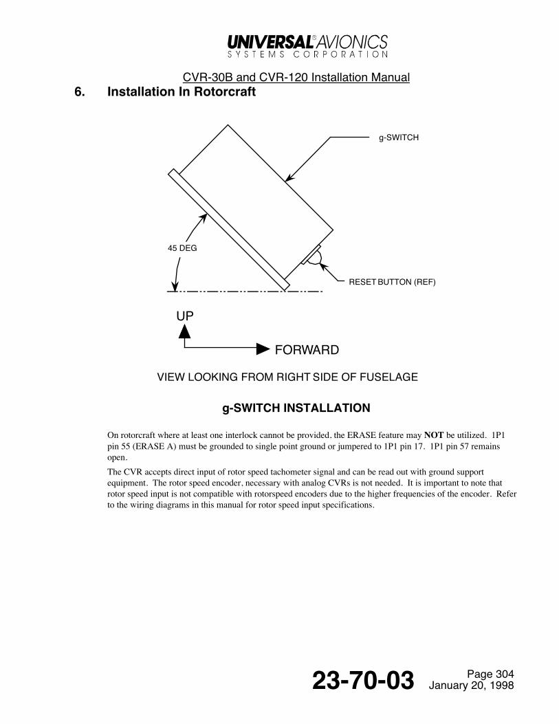
It is imperative that the installer be familiar with the rules, regulations and recommendations of the certifyingagency.Refer to the figure for a typical 45° g-Switch installation.Some acceptable switches are:
Inertia Switch, Inc.269 N Rte. 303West Nyack, NY 10994
P/N 3LO-453/3 (3-g activation)or
P/N 3LO-453/4 (4-g activation)
Aerodyne Controls Corp30 Haynes CourtRonkonkoma, NY 11779
P/N 6895-D-1-3-5 (3-g)or
P/N 6895-D-1-4-4 (4-g)
CVR-30B and CVR-120 Installation Manual
Page 30423-70-03 January 20, 1998
6. Installation In Rotorcraft
45 DEG
FORWARD
UP
RESET BUTTON (REF)
g-SWITCH
VIEW LOOKING FROM RIGHT SIDE OF FUSELAGE
g-SWITCH INSTALLATION
On rotorcraft where at least one interlock cannot be provided, the ERASE feature may NOT be utilized. 1P1pin 55 (ERASE A) must be grounded to single point ground or jumpered to 1P1 pin 17. 1P1 pin 57 remainsopen.The CVR accepts direct input of rotor speed tachometer signal and can be read out with ground supportequipment. The rotor speed encoder, necessary with analog CVRs is not needed. It is important to note thatrotor speed input is not compatible with rotorspeed encoders due to the higher frequencies of the encoder. Referto the wiring diagrams in this manual for rotor speed input specifications.
CVR-30B and CVR-120 Installation Manual
Page 30523-70-03 January 20, 1998
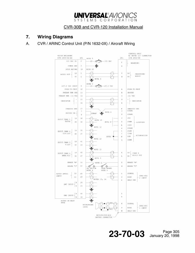
7. Wiring DiagramsA. CVR / ARINC Control Unit (P/N 1632-0X) / Aircraft Wiring

CVR-30B and CVR-120 Installation Manual
Page 30623-70-03 January 20, 1998
NOTES:
1. ALL WIRES ARE 22 AWG UNLESS SPECIFIED OTHERWISE.2. NOT USED.3. NOT USED4. SINGLE POINT GROUND WITHIN 12" OF 1P1 PIN 17.5. ONLY ONE POWER SOURCE CAN BE CONNECTED AT A TIME. CONNECT EITHER 1P1 PIN 2 OR PIN 9,
NOT BOTH.6. CONNECT EITHER 5V OR 28V, NOT BOTH.7. 30dB ATTENUATION SHOWN. WIRE ACCORDINGLY. QUIET COCKPITS MAY BE STRAPPED FOR
LESS ATTENUATION. ATTENUATION SHOULD BE SUCH THAT THE SIGNAL LEVEL INDICATOR ONTHE CONTROL UNIT AND/OR TEST SET ILLUMINATES TWO-THIRDS TO THREE-FOURTHS OF THELEDS DURING NORMAL CONVERSATIONS.
8. SQUAT SWITCH CLOSED WITH WEIGHT ON GEAR.9. PARK BRAKE SWITCH CLOSED WITH BRAKE SET.10. WHEN GROUNDED, A 10 MINUTE TIMER IS STARTED. AFTER 10 MINUTES, RECORDING AND
ERASURE IS INHIBITED. REMOVAL OF GROUND RESETS TIMER.11. IF ERASE IS NOT DESIRED, 1P1 PIN 55 MUST BE GROUNDED TO SINGLE POINT GROUND (SEE NOTE
4) OR JUMPERED TO 1P1 PIN 17. 1P1 PIN 57 AND 2P1 PINS G AND H WILL BE LEFT OPEN.12. WIRING SHOWN IN ACCORDANCE WITH ARINC 757 (SINGLE POINT GROUND WITHIN 12" OF 1P1 PIN
17). HOWEVER, IT IS ACCEPTABLE TO GROUND AUDIO SHIELDS AT THE SOURCE. DO NOTGROUND BOTH ENDS OF SHIELD.
13. SHIELD IS TO BE GROUNDED AT SOURCE.14. ROTOR SPEED INPUT SPECS;
FREQUENCY - 10 TO 15,000 HzIMPEDANCE = 200 K OHMS.2 VOLTS MIN., 100V MAX.ROTOR SPEED INPUT IS NOT COMPATIBLE WITH ROTOR SPEED ENCODERS DUE TO THEIR HIGHFREQUENCIES. THE CVR ACCEPTS INPUTS DIRECTLY FROM THE ROTOR TACH.
15. INPUT CHAN 1 (EXTRA) CAN BE USED TO ACCEPT FLIGHT DATA RECORDER TONE OUTPUT FORRECORDER SYNCHRONIZATION. FDR PIN 19 CONNECTS TO CVR PIN 32 AND FDR PIN 20 CONNECTSTO CVR PIN 30. NO STANDARDIZATION OF THE SIGNAL CHARACTERISTICS, LEVELS OR OTHERPARAMETERS OF THE TIMING SIGNAL FROM THE AIRBORNE FLIGHT DATA RECORDER HAS BEENADOPTED. IT IS THE INSTALLER’S RESPONSIBILITY TO ASSURE THAT THE FDR TIMING SIGNALOUTPUT IS COMPATIBLE WITH THE CVR. CVR INPUT LIMITS ARE AS FOLLOWS;LOW FREQ LIMIT = 3607 ± 30 HZ / HIGH FREQ LIMIT = 4193±30 HZ.LEVEL = .5 Vrms TO 2.5 Vrms.TYPE = SINEWAVE OR TRIANGLE
CVR-30B and CVR-120 Installation Manual
Page 30723-70-03 January 20, 1998
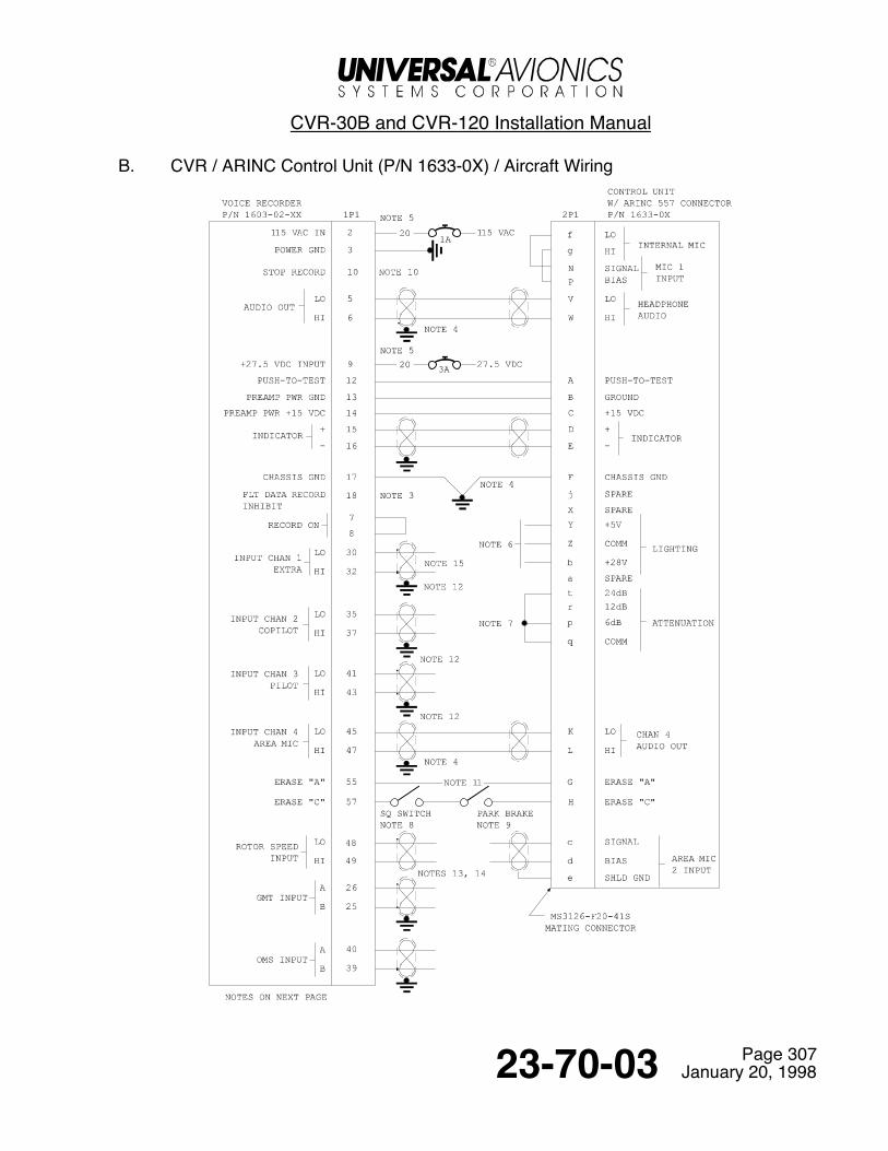
B. CVR / ARINC Control Unit (P/N 1633-0X) / Aircraft Wiring

CVR-30B and CVR-120 Installation Manual
Page 30823-70-03 January 20, 1998
NOTES:
1. ALL WIRES ARE 22 AWG UNLESS SPECIFIED OTHERWISE.2. NOT USED.3. NOT USED.4. SINGLE POINT GROUND WITHIN 12" OF 1P1 PIN 17.5. ONLY ONE POWER SOURCE CAN BE CONNECTED AT A TIME. CONNECT EITHER 1P1 PIN 2 OR PIN 9,
NOT BOTH.6. CONNECT EITHER 5V OR 28V, NOT BOTH.7. 30dB ATTENUATION SHOWN. WIRE ACCORDINGLY. QUIET COCKPITS MAY BE STRAPPED FOR
LESS ATTENUATION. ATTENUATION SHOULD BE SUCH THAT THE SIGNAL LEVEL INDICATOR ONTHE CONTROL UNIT AND/OR TEST SET ILLUMINATES TWO-THIRDS TO THREE-FOURTHS OF THELEDS DURING NORMAL CONVERSATIONS.
8. SQUAT SWITCH CLOSED WITH WEIGHT ON GEAR.9. PARK BRAKE SWITCH CLOSED WITH BRAKE SET.10. WHEN GROUNDED, A 10 MINUTE TIMER IS STARTED. AFTER 10 MINUTES, RECORDING AND
ERASURE IS INHIBITED. REMOVAL OF GROUND RESETS TIMER.11. IF ERASE IS NOT DESIRED, 1P1 PIN 55 MUST BE GROUNDED TO SINGLE POINT GROUND (SEE NOTE
4) OR JUMPERED TO 1P1 PIN 17. 1P1 PIN 57 AND 2P1 PINS G AND H WILL BE LEFT OPEN.12. WIRING SHOWN IN ACCORDANCE WITH ARINC 757 (SINGLE POINT GROUND WITHIN 12" OF 1P1 PIN
17). HOWEVER, IT IS ACCEPTABLE TO GROUND AUDIO SHIELDS AT THE SOURCE. DO NOTGROUND BOTH ENDS OF SHIELD.
13. SHIELD IS TO BE GROUNDED AT SOURCE.14. ROTOR SPEED INPUT SPECS;
FREQUENCY - 10 TO 15,000 HzIMPEDANCE = 200 K OHMS.2 VOLTS MIN., 100V MAX.ROTOR SPEED INPUT IS NOT COMPATIBLE WITH ROTOR SPEED ENCODERS DUE TO THEIR HIGHFREQUENCIES. THE CVR ACCEPTS INPUTS DIRECTLY FROM THE ROTOR TACH.
15. INPUT CHAN 1 (EXTRA) CAN BE USED TO ACCEPT FLIGHT DATA RECORDER TONE OUTPUT FORRECORDER SYNCHRONIZATION. FDR PIN 19 CONNECTS TO CVR PIN 32 AND FDR PIN 20 CONNECTSTO CVR PIN 30. NO STANDARDIZATION OF THE SIGNAL CHARACTERISTICS, LEVELS OR OTHERPARAMETERS OF THE TIMING SIGNAL FROM THE AIRBORNE FLIGHT DATA RECORDER HAS BEENADOPTED. IT IS THE INSTALLER’S RESPONSIBILITY TO ASSURE THAT THE FDR TIMING SIGNALOUTPUT IS COMPATIBLE WITH THE CVR. CVR INPUT LIMITS ARE AS FOLLOWS;LOW FREQ LIMIT = 3607 ± 30 HZ / HIGH FREQ LIMIT = 4193±30 HZ.LEVEL = .5 Vrms TO 2.5 Vrms.TYPE = SINEWAVE OR TRIANGLE

CVR-30B and CVR-120 Installation Manual
Page 30923-70-03 January 20, 1998
C. CVR / Slimline Control Unit (P/N 1634-0X) / Aircraft Wiring
CVR-30B and CVR-120 Installation Manual
Page 31023-70-03 January 20, 1998
NOTES:
1. ALL WIRES ARE 22 AWG UNLESS SPECIFIED OTHERWISE.2. NOT USED.3. NOT USED.4. SINGLE POINT GROUND WITHIN 12" OF 1P1 PIN 17.5. ONLY ONE POWER SOURCE CAN BE CONNECTED AT A TIME. CONNECT EITHER 1P1 PIN 2 OR PIN 9,
NOT BOTH.6. CONNECT EITHER 5V OR 28V, NOT BOTH.7. 30dB ATTENUATION SHOWN. WIRE ACCORDINGLY. QUIET COCKPITS MAY BE STRAPPED FOR
LESS ATTENUATION. ATTENUATION SHOULD BE SUCH THAT THE SIGNAL LEVEL INDICATOR ONTHE CONTROL UNIT AND/OR TEST SET ILLUMINATES TWO-THIRDS TO THREE-FOURTHS OF THELEDS DURING NORMAL CONVERSATIONS.
8. SQUAT SWITCH CLOSED WITH WEIGHT ON GEAR.9. PARK BRAKE SWITCH CLOSED WITH BRAKE SET.10. WHEN GROUNDED, A 10 MINUTE TIMER IS STARTED. AFTER 10 MINUTES, RECORDING AND
ERASURE IS INHIBITED. REMOVAL OF GROUND RESETS TIMER.11. IF ERASE IS NOT DESIRED, 1P1 PIN 55 MUST BE GROUNDED TO SINGLE POINT GROUND (SEE NOTE
4) OR JUMPERED TO 1P1 PIN 17. 1P1 PIN 57 AND 2P1 PINS 32 AND 31 WILL BE LEFT OPEN.12. WIRING SHOWN IN ACCORDANCE WITH ARINC 757 (SINGLE POINT GROUND WITHIN 12" OF 1P1 PIN
17). HOWEVER, IT IS ACCEPTABLE TO GROUND AUDIO SHIELDS AT THE SOURCE. DO NOTGROUND BOTH ENDS OF SHIELD.
13. SHIELD IS TO BE GROUNDED AT SOURCE.14. ROTOR SPEED INPUT SPECS;
FREQUENCY - 10 TO 15,000 HzIMPEDANCE = 200 K OHMS.2 VOLTS MIN., 100V MAX.ROTOR SPEED INPUT IS NOT COMPATIBLE WITH ROTOR SPEED ENCODERS DUE TO THEIR HIGHFREQUENCIES. THE CVR ACCEPTS INPUTS DIRECTLY FROM THE ROTOR TACH.
15. INPUT CHAN 1 (EXTRA) CAN BE USED TO ACCEPT FLIGHT DATA RECORDER TONE OUTPUT FORRECORDER SYNCHRONIZATION. FDR PIN 19 CONNECTS TO CVR PIN 32 AND FDR PIN 20 CONNECTSTO CVR PIN 30. NO STANDARDIZATION OF THE SIGNAL CHARACTERISTICS, LEVELS OR OTHERPARAMETERS OF THE TIMING SIGNAL FROM THE AIRBORNE FLIGHT DATA RECORDER HAS BEENADOPTED. IT IS THE INSTALLER’S RESPONSIBILITY TO ASSURE THAT THE FDR TIMING SIGNALOUTPUT IS COMPATIBLE WITH THE CVR. CVR INPUT LIMITS ARE AS FOLLOWS;LOW FREQ LIMIT = 3607 ± 30 HZ / HIGH FREQ LIMIT = 4193±30 HZ.LEVEL = .5 Vrms TO 2.5 Vrms.TYPE = SINEWAVE OR TRIANGLE
!"#$%&'%$"'(%')*+&,-./0.1022 ,),
'%3"4%&3#$&53)6#7#%'8*5'#+$&99:&$"++%$4"')*+&,-/:0.1&&+"4%&-
,,9&!5$&#+ 1
)"8%'&;+( /
<1:=9&!($&#+)>4 ?
@
A
B
C#;+56
D#5C
CE6(&;+(
5'%5&3#$1&#+)>4
,5 ,,9&!5$
+"4%&9
1:=9&!($+"4%&9
+"4%&-
/5
+
)
3
C#;+56
D#5C
CE6(&;+(
5'%5&3#$,&#+)>4
3#$'")E"+%,-/.,
)'%53)&)8'&;+( ,/
)'%53)&)8'&<,9&!($ ,F
,:$E5CC#C&;+(
+"4%&F
D
$
7
;'">+(
<,9&!($
$E5CC#C&;+(
'%$"'(&"+
#+)>4&$E5+&,%24'5
6"
E#
/.
/1
+"4%&,/
GH
I
J
1FAD,1AD
-AD
$"33
544%+>54#"++"4%&:
+"4%&F
#+)>4&$E5+&F5'%5&3#$
6"
E#
F9
F:
K
6
6"
E#
$E5+&F5>(#"&">4
9!&">4L
%'5C%&M5M 99
+"4%C&"+&+%24&)5;%
6"
E#
'"4"'&C)%%(#+)>4
+"4%C&,FN&,9
FO
F?
1.
1.
1.
+"4%&,,
D6K
8E4
+"4%&,-
C4")&'%$"'( ,. +"4%&,.
:
OC4'5)
#+)>4&$E5+&1$")#6"4
6"
E#
/9
/:
+"4%&,/
#+)>4&$E5+&/)#6"4
6"
E#
F,
F/
+"4%&,/
;34&#+)>45
D
1-
19
"3C&#+)>45
D
F.
/?
E%5(C%4&P5$K
+"4%&,1
+"4%&F
5>(#"&">46"
E#
9
-
%'5C%&M$M 9:
/5,51
/
F
;&D 5
,
1
/
F
,$
D
(
5
(%45#6&"7&C8#4$E&5C!#%8%(&7'"3&4E%&D5$K
/D
5#'$'5745++>+$#54"'D>CE#
D $
5 (
15 F5
,D
FD
+"4%&,1
$!'%'5C%
6"
;
1D
CQ&C8#4$E+"4%&O
)5'K&D'5K%+"4%&?
R
S )5CC&6"
75#6&6",1)>CE&4"&4%C4
$!'&4%C4
)5CC 75#6
5#'$'5745++>+$#54"'D>CE#
D $
5 (
,5
15
/5
F5
+"4%&,1
6"
;
#+(#$54"'<
0
,9
,-
'%3"4%&3#$&53)6#7#%'8*5'#+$&99:&$"++%$4"')*+&,-/:0.1&&+"4%&-
(
%
<
0#+(#$54"'
CVR-30B and CVR-120 Installation Manual
Page 31123-70-03 January 20, 1998
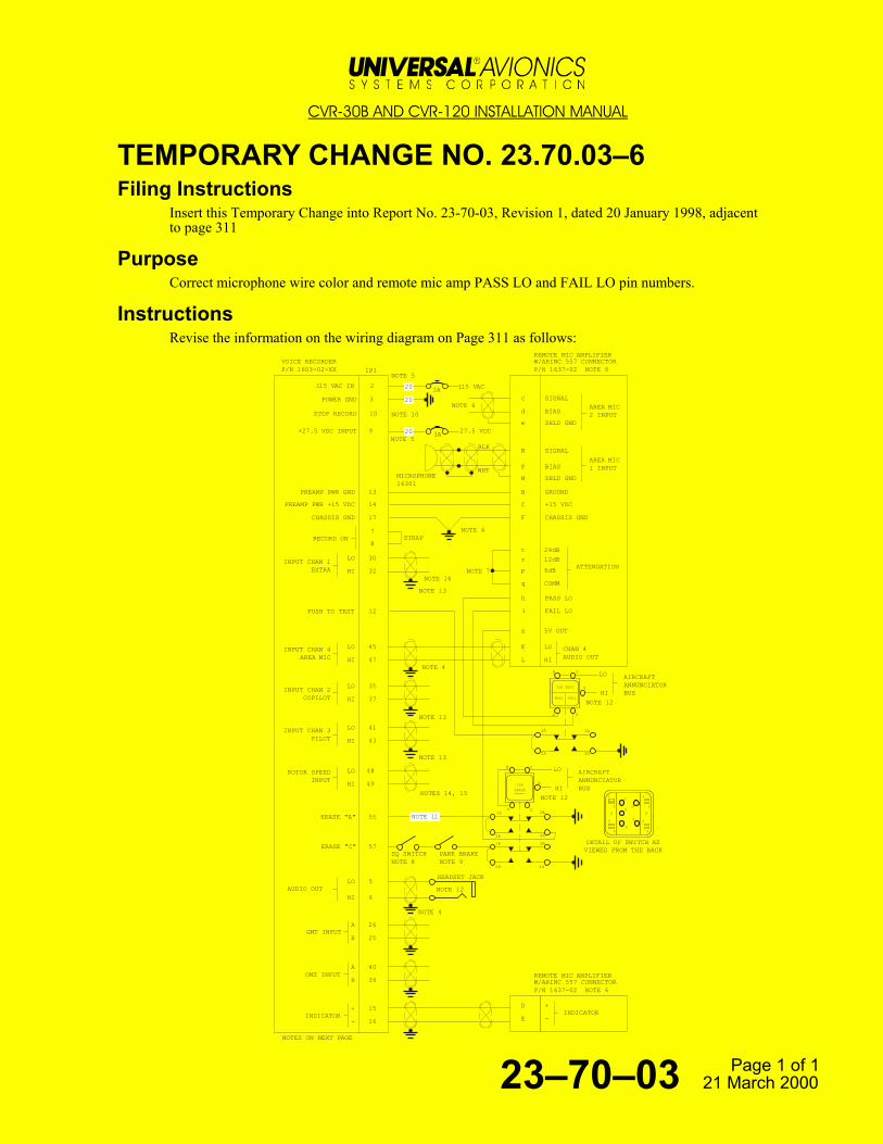
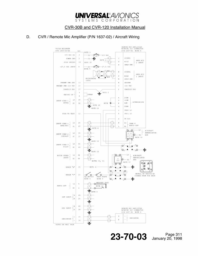
D. CVR / Remote Mic Amplifier (P/N 1637-02) / Aircraft Wiring

CVR-30B and CVR-120 Installation Manual
Page 31223-70-03 January 20, 1998
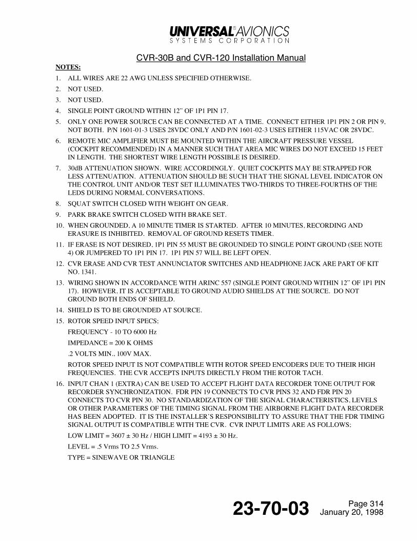
NOTES: 1. ALL WIRES ARE 22 AWG UNLESS SPECIFIED OTHERWISE.
2. NOT USED.3. NOT USED.4. SINGLE POINT GROUND WITHIN 12" OF 1P1 PIN 17.5. ONLY ONE POWER SOURCE CAN BE CONNECTED AT A TIME. CONNECT EITHER 1P1 PIN 2 OR PIN 9,
NOT BOTH.6. REMOTE MIC AMPLIFIER MUST BE MOUNTED WITHIN THE AIRCRAFT PRESSURE VESSEL
(COCKPIT RECOMMENDED) IN A MANNER SUCH THAT AREA MIC WIRES DO NOT EXCEED 15 FEETIN LENGTH. THE SHORTEST WIRE LENGTH POSSIBLE IS DESIRED.
7. 30dB ATTENUATION SHOWN. WIRE ACCORDINGLY. QUIET COCKPITS MAY BE STRAPPED FORLESS ATTENUATION. ATTENUATION SHOULD BE SUCH THAT THE SIGNAL LEVEL INDICATOR ONTHE CONTROL UNIT AND/OR TEST SET ILLUMINATES TWO-THIRDS TO THREE-FOURTHS OF THELEDS DURING NORMAL CONVERSATIONS.
8. SQUAT SWITCH CLOSED WITH WEIGHT ON GEAR9. PARK BRAKE SWITCH CLOSED WITH BRAKE SET.10. WHEN GROUNDED, A 10 MINUTE TIMER IS STARTED. AFTER 10 MINUTES, RECORDING AND
ERASURE IS INHIBITED. REMOVAL OF GROUND RESETS TIMER.11. IF ERASE IS NOT DESIRED, 1P1 PIN 55 MUST BE GROUNDED TO SINGLE POINT GROUND (SEE NOTE
4) OR JUMPERED TO 1P1 PIN 17. 1P1 PIN 57 WILL BE LEFT OPEN.12. CVR ERASE AND CVR TEST ANNUNCIATOR SWITCHES AND HEADPHONE JACK ARE PART OF KIT
NO 1341.13. WIRING SHOWN IN ACCORDANCE WITH ARINC 757 (SINGLE POINT GROUND WITHIN 12" OF 1P1 PIN
17). HOWEVER, IT IS ACCEPTABLE TO GROUND AUDIO SHIELDS AT THE SOURCE. DO NOTGROUND BOTH ENDS OF SHIELD.
14. SHIELD IS TO BE GROUNDED AT SOURCE.15. ROTOR SPEED INPUT SPECS;
FREQUENCY - 10 TO 15,000 HzIMPEDANCE = 200 K OHMS.2 VOLTS MIN., 100V MAX.ROTOR SPEED INPUT IS NOT COMPATIBLE WITH ROTOR SPEED ENCODERS DUE TO THEIR HIGHFREQUENCIES. THE CVR ACCEPTS INPUTS DIRECTLY FROM THE ROTOR TACH.
16. INPUT CHAN 1 (EXTRA) CAN BE USED TO ACCEPT FLIGHT DATA RECORDER TONE OUTPUT FORRECORDER SYNCHRONIZATION. FDR PIN 19 CONNECTS TO CVR PIN 32 AND FDR PIN 20 CONNECTSTO CVR PIN 30. NO STANDARDIZATION OF THE SIGNAL CHARACTERISTICS, LEVELS OR OTHERPARAMETERS OF THE TIMING SIGNAL FROM THE AIRBORNE FLIGHT DATA RECORDER HAS BEENADOPTED. IT IS THE INSTALLER’S RESPONSIBILITY TO ASSURE THAT THE FDR TIMING SIGNALOUTPUT IS COMPATIBLE WITH THE CVR. CVR INPUT LIMITS ARE AS FOLLOWS;LOW FREQ LIMIT = 3607 ± 30 HZ / HIGH FREQ LIMIT = 4193±30 HZ.LEVEL = .5 Vrms TO 2.5 Vrms.TYPE = SINEWAVE OR TRIANGLE

CVR-30B and CVR-120 Installation Manual
Page 31323-70-03 January 20, 1998
E. CVR / Remote Mic Amplifier, Slimline (P/N 1635-02) / Aircraft Wiring
CVR-30B and CVR-120 Installation Manual
Page 31423-70-03 January 20, 1998
NOTES: 1. ALL WIRES ARE 22 AWG UNLESS SPECIFIED OTHERWISE.2. NOT USED.3. NOT USED.4. SINGLE POINT GROUND WITHIN 12” OF 1P1 PIN 17.5. ONLY ONE POWER SOURCE CAN BE CONNECTED AT A TIME. CONNECT EITHER 1P1 PIN 2 OR PIN 9,
NOT BOTH. P/N 1601-01-3 USES 28VDC ONLY AND P/N 1601-02-3 USES EITHER 115VAC OR 28VDC.6. REMOTE MIC AMPLIFIER MUST BE MOUNTED WITHIN THE AIRCRAFT PRESSURE VESSEL
(COCKPIT RECOMMENDED) IN A MANNER SUCH THAT AREA MIC WIRES DO NOT EXCEED 15 FEETIN LENGTH. THE SHORTEST WIRE LENGTH POSSIBLE IS DESIRED.
7. 30dB ATTENUATION SHOWN. WIRE ACCORDINGLY. QUIET COCKPITS MAY BE STRAPPED FORLESS ATTENUATION. ATTENUATION SHOULD BE SUCH THAT THE SIGNAL LEVEL INDICATOR ONTHE CONTROL UNIT AND/OR TEST SET ILLUMINATES TWO-THIRDS TO THREE-FOURTHS OF THELEDS DURING NORMAL CONVERSATIONS.
8. SQUAT SWITCH CLOSED WITH WEIGHT ON GEAR.9. PARK BRAKE SWITCH CLOSED WITH BRAKE SET.10. WHEN GROUNDED, A 10 MINUTE TIMER IS STARTED. AFTER 10 MINUTES, RECORDING AND
ERASURE IS INHIBITED. REMOVAL OF GROUND RESETS TIMER.11. IF ERASE IS NOT DESIRED, 1P1 PIN 55 MUST BE GROUNDED TO SINGLE POINT GROUND (SEE NOTE
4) OR JUMPERED TO 1P1 PIN 17. 1P1 PIN 57 WILL BE LEFT OPEN.12. CVR ERASE AND CVR TEST ANNUNCIATOR SWITCHES AND HEADPHONE JACK ARE PART OF KIT
NO. 1341.13. WIRING SHOWN IN ACCORDANCE WITH ARINC 557 (SINGLE POINT GROUND WITHIN 12” OF 1P1 PIN
17). HOWEVER, IT IS ACCEPTABLE TO GROUND AUDIO SHIELDS AT THE SOURCE. DO NOTGROUND BOTH ENDS OF SHIELD.
14. SHIELD IS TO BE GROUNDED AT SOURCE.15. ROTOR SPEED INPUT SPECS;
FREQUENCY - 10 TO 6000 HzIMPEDANCE = 200 K OHMS.2 VOLTS MIN., 100V MAX.ROTOR SPEED INPUT IS NOT COMPATIBLE WITH ROTOR SPEED ENCODERS DUE TO THEIR HIGHFREQUENCIES. THE CVR ACCEPTS INPUTS DIRECTLY FROM THE ROTOR TACH.
16. INPUT CHAN 1 (EXTRA) CAN BE USED TO ACCEPT FLIGHT DATA RECORDER TONE OUTPUT FORRECORDER SYNCHRONIZATION. FDR PIN 19 CONNECTS TO CVR PINS 32 AND FDR PIN 20CONNECTS TO CVR PIN 30. NO STANDARDIZATION OF THE SIGNAL CHARACTERISTICS, LEVELSOR OTHER PARAMETERS OF THE TIMING SIGNAL FROM THE AIRBORNE FLIGHT DATA RECORDERHAS BEEN ADOPTED. IT IS THE INSTALLER’S RESPONSIBILITY TO ASSURE THAT THE FDR TIMINGSIGNAL OUTPUT IS COMPATIBLE WITH THE CVR. CVR INPUT LIMITS ARE AS FOLLOWS;LOW LIMIT = 3607 ± 30 Hz / HIGH LIMIT = 4193 ± 30 Hz.LEVEL = .5 Vrms TO 2.5 Vrms.TYPE = SINEWAVE OR TRIANGLE

CVR-30B and CVR-120 Installation Manual
Page 31523-70-03 January 20, 1998
8. Pin Out ChartsA. CVR Pin Out
CVR P/N 1603-02-XX / 1P1Pin Function12 115 VAC Input3 Power Ground45 Audio Out - Lo6 Audio Out - Hi7 Record On Strap (To Pin 8)8 Record On Strap (To Pin 7)9 +27.5 VDC Input10 Stop Record1112 Push To Test13 Preamp Power Ground14 Preamp Power - + 15 VDC15 Indicator +16 Indicator -17 Chassis Ground181920212223 Fault CVR (norm low)24 Fault FDR25 GMT Input (B)26 GMT Input (A)2728
Continued -
CVR P/N 1603-02-XX / 1P1 - Cont’dPin Function2930 INPUT Chan 1 (Extra) - Lo3132 INPUT Chan 1 (Extra) - Hi333435 INPUT Chan 2 (Copilot) - Lo3637 INPUT Chan 2 (Copilot) - Hi3839 OMS Input (B)40 OMS Input (A)41 INPUT Chan 3 (Pilot) - Lo4243 INPUT Chan 3 (Pilot - Hi4445 INPUT Chan 4 (Area Mic) - Lo4647 INPUT Chan 4 (Area Mic) - Hi48 Rotor Speed - Lo49 Rotor Speed - Hi50 OMS Out (B)51 OMS Out (A)52535455 Erase ‘A’5657 Erase ‘C’
CVR-30B and CVR-120 Installation Manual
Page 31623-70-03 January 20, 1998
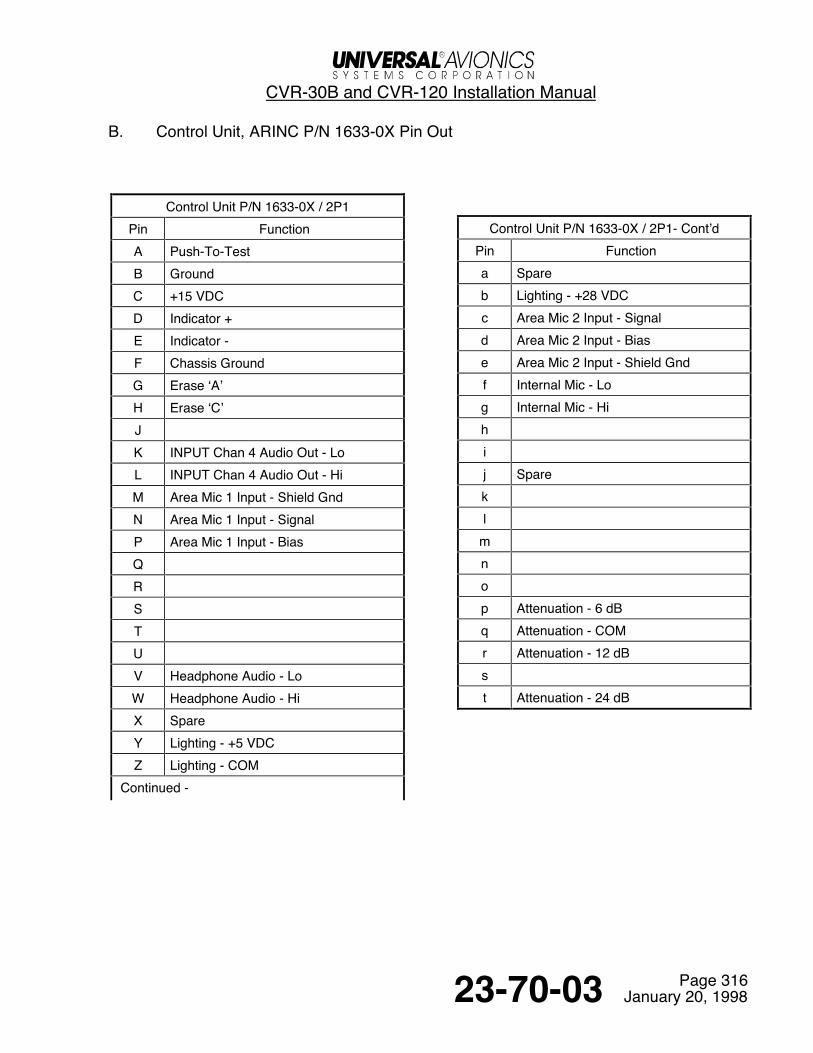
B. Control Unit, ARINC P/N 1633-0X Pin Out
Control Unit P/N 1633-0X / 2P1Pin FunctionA Push-To-TestB GroundC +15 VDCD Indicator +E Indicator -F Chassis GroundG Erase ‘A’H Erase ‘C’JK INPUT Chan 4 Audio Out - LoL INPUT Chan 4 Audio Out - HiM Area Mic 1 Input - Shield GndN Area Mic 1 Input - SignalP Area Mic 1 Input - BiasQRSTUV Headphone Audio - LoW Headphone Audio - HiX SpareY Lighting - +5 VDCZ Lighting - COM
Continued -
Control Unit P/N 1633-0X / 2P1- Cont’dPin Functiona Spareb Lighting - +28 VDCc Area Mic 2 Input - Signald Area Mic 2 Input - Biase Area Mic 2 Input - Shield Gndf Internal Mic - Log Internal Mic - Hihij Sparekl
mnop Attenuation - 6 dBq Attenuation - COMr Attenuation - 12 dBst Attenuation - 24 dB

CVR-30B and CVR-120 Installation Manual
Page 31723-70-03 January 20, 1998
C. Control Unit, ARINC P/N 1632-0X Pin Out
Control Unit P/N 1632-0X / 2P1Pin FunctionA Push-To-TestB GroundC +15 VDCD Indicator +E Indicator -F Chassis GroundG Erase ‘A’H Erase ‘C’JK Chan 4 Audio Out - LoL Chan 4 Audio Out - HiM Area Mic 1 Input - Shield GndNPQRSTUV Headphone Audio - LoW Headphone Audio - HiX SpareY Lighting - +5 VDCZ Lighting - COM
Continued -
Control Unit P/N 1632-0X / 2P1- Cont’dPin Functiona Spareb Lighting - +28 VDCc Area Mic 2 Input - Signald Area Mic 2 Input - Biase Area Mic 2 Input - Shield Gndfghij Sparekl
mnop Attenuation - 6 dBq Attenuation - COMr Attenuation - 12 dBst Attenuation - 24 dB
CVR-30B and CVR-120 Installation Manual
Page 31823-70-03 January 20, 1998
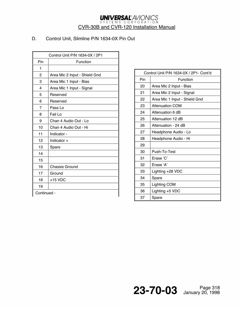
D. Control Unit, Slimline P/N 1634-0X Pin Out
Control Unit P/N 1634-0X / 2P1Pin Function12 Area Mic 2 Input - Shield Gnd3 Area Mic 1 Input - Bias4 Area Mic 1 Input - Signal5 Reserved6 Reserved7 Pass Lo8 Fail Lo9 Chan 4 Audio Out - Lo10 Chan 4 Audio Out - Hi11 Indicator -12 Indicator +13 Spare141516 Chassis Ground17 Ground18 +15 VDC19
Continued -
Control Unit P/N 1634-0X / 2P1- Cont’dPin Function20 Area Mic 2 Input - Bias21 Area Mic 2 Input - Signal22 Area Mic 1 Input - Shield Gnd23 Attenuation COM24 Attenuation 6 dB25 Attenuation 12 dB26 Attenuation - 24 dB27 Headphone Audio - Lo28 Headphone Audio - Hi2930 Push-To-Test31 Erase ‘C’32 Erase ‘A’33 Lighting +28 VDC34 Spare35 Lighting COM36 Lighting +5 VDC37 Spare


CVR-30B and CVR-120 Installation Manual
Page 31923-70-03 January 20, 1998
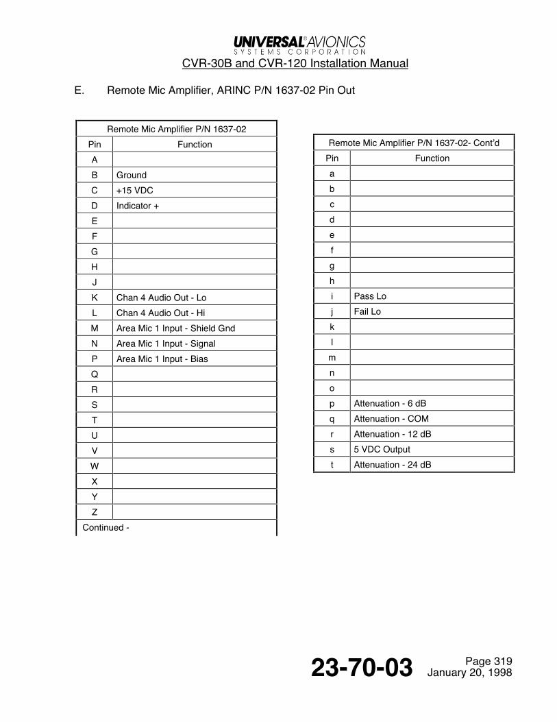
E. Remote Mic Amplifier, ARINC P/N 1637-02 Pin Out
Remote Mic Amplifier P/N 1637-02Pin FunctionAB GroundC +15 VDCD Indicator +EFGHJK Chan 4 Audio Out - LoL Chan 4 Audio Out - HiM Area Mic 1 Input - Shield GndN Area Mic 1 Input - SignalP Area Mic 1 Input - BiasQRSTUVWXYZ
Continued -
Remote Mic Amplifier P/N 1637-02- Cont’dPin Functionabcdefghi Pass Loj Fail Lokl
mnop Attenuation - 6 dBq Attenuation - COMr Attenuation - 12 dBs 5 VDC Outputt Attenuation - 24 dB

CVR-30B and CVR-120 Installation Manual
Page 32023-70-03 January 20, 1998
F. Remote Mic Amplifier, Slimline P/N 1635-02 Pin Out
Remote Mic Amplifier P/N 1635-02 / 2P1Pin Function12 Area Mic 2 Input - Shield Gnd3 Area Mic 1 Input - Bias4 Area Mic 1 Input - Signal5 Reserved6 Reserved789 Chan 4 Audio Out - Lo10 Chan 4 Audio Out - Hi11 Indicator -12 Indicator +13 Spare141516 Chassis Ground17 Ground18 +15 VDC19
Continued -
Remote Mic Amp P/N 1635-02 / 2P1- Cont’dPin Function20 Area Mic 2 Input - Bias21 Area Mic 2 Input - Signal22 Area Mic 1 Input - Shield Gnd23 Attenuation COM24 Attenuation 6 dB25 Attenuation 12 dB26 Attenuation - 24 dB27 Headphone Audio - Lo28 Headphone Audio - Hi2930 Push-To-Test31 Erase ‘C’32 Erase ‘A’33 Lighting +28 VDC34 Spare35 Lighting COM36 Lighting +5 VDC37 Spare
Return to Table of Contents
CVR-30B and CVR-120 Installation Manual
Page 40123-70-03 January 20, 1998
Maintenance, Checkout and Troubleshooting1. Maintenance
CVR Maintenance includes Periodic Inspections of the CVR and Underwater Locator Beacon (ULB) as well asServicing/Maintenance of the ULB.
A. Periodic Inspections/OverhaulCVR Periodic Inspection consists of the required preflight self test. Only if a self test fails, is maintenance needon the CVR.
(1) CVR OverhaulBecause of the solid state technology used in the CVR, there is no need for periodic overhaul of the CVR.MTBF has been established at 30,000 hours.
(2) Underwater Locator Beacon Periodic InspectionNOTE: The following inspections are dictated by the Dukane Technical Manual.
INSPECTION INTERVAL TASK
24 Months 1. Clean ULB Beacon Switch
2. Perform ULB Beacon Test
3. Perform ULB Battery Test
6 Years 1. Replace ULB Beacon Battery
B. Underwater Locator Beacon Servicing / MaintenanceThe CVR utilizes the Dukane Model DK120 underwater acoustic beacon which is manufactured under a PartsManufacturer Approval (PMA) and is authorized by FAA TSO-C121. The beacon is attached to the recorderenvironmental shell for easy removal and for easy viewing of the battery expiration date.
The battery in the Model DK120 has a life of six years. The battery is user replaceable. Refer to TechnicalManual, Underwater Acoustic Beacon, DK100/DK120 for maintenance and battery replacement. ContactDukane for details.

CVR-30B and CVR-120 Installation Manual
Page 40223-70-03 January 20, 1998
2. Post-Installation Checkout ProcedureNOTE: • It will be helpful if the following checkout procedures are copied, filled out and presented
along with other supporting documents when applying for approval. Permission is herebygranted to copy this portion of this manual.
• The following procedures are written for installation with Control Unit P/N 1632-0X,1633-0X or 1634-0X. On installations utilizing Remote Mic Amplifier P/N 1635-0X or1637-0X and Annunciator/Switch Kit P/N 1341, disregard all references to SIGNALLEVEL Indicator.
The CVR Self Test gives an indication of the Pass or Fail condition.
During Self Test, the following occurs:
(1) A test tone will be recorded onto all six channels and then followed by a period of silence. Items testedduring the self test include; power supply voltages, ARINC 429 Built In Test Equipment (BITE), ARINC429 Onboard Maintenance System(OMS) receiver, FSK GMT receiver, EPROM checksum and rotorspeed receiver.
(2) The test tone and silence is then automatically played back and read internally.(3) The PASS or FAIL LED will then illuminate for 10 seconds. The SIGNAL LEVEL Indicator will also
illuminate for 10 seconds with the FAIL LED.After installation is accomplished and all wiring, power sources and audio interface is verified, apply power tothe system.
Self Test
(1) Don headset and plug into the control unit headphone jack.(2) Press the control unit TEST Button firmly for at least two seconds and release. This initiates the CVR
Self Test.(3) During self test the PASS and FAIL LEDs will illuminate alternately indicating that self test is in
progress. Self test takes approximately 15 seconds to perform. After 10 seconds of self test, cockpitconversation should be heard through the headset and visible on the SIGNAL LEVEL Indicator. The testtone audio will be heard. No audio will be recorded during self test.
NOTE: Self test will not initiate if the erase feature is in progress. Self test will not function if Stop Record is initiated. When power is removed and then applied to the CVR, if “STOPRECORD” is active, it will be ignored. “STOP RECORD” must go from an inactive to activecondition to be properly recognized. This means that the CVR will immediately start torecord upon application of power if “RECORD ON” is ON and “GND EQ INTLK” is OFF,regardless of the condition of “STOP RECORD”.

CVR-30B and CVR-120 Installation Manual
Page 40323-70-03 January 20, 1998
(4) Upon completion of a successful self test, the PASS Light will illuminate for approximately ten secondsthen go out. A failed self test will be indicated by an illuminated FAIL Light (usually flashing). Theflashing FAIL Light indicates the nature of the failure. FAIL will flash a number of times, pause, andthen repeat that same number of flashes. The following table shows the fail condition based on thenumber of FAIL flashes.
Number ofFAIL flashes
CVR Condition FAIL Light PASS Light
None Pass Off On
1 Channel 1 fail On Off
2 Channel 2 fail On Off
3 Channel 3 fail On Off
4 Channel 4 fail On Off
5 Flash Memory Fail On Off
Steady (10 secs) General failure (Note 1) On Off
Alternating System test in progress Alternating Alternating
Simultaneous Bulk Erase Simultaneous Simultaneous
NOTE: 1. General failure is a misc. failure of Ch. 5, 6, FSK, Rotor Speed, ARINC Channels, etc. The BITE Status code indicates whichfunction has failed. Please contact Universal Avionics forassistance with determining a particular BITE Status failureindication.
(5) Should self test fail and it is desired to perform another self test, the TEST Button must be pressed firmlyfor at least one second to engage self test.
Erase (if applicable)
(1) Open squat switch and parking brake switch (air mode) (and/or any other interlock switches).NOTE: The ERASE Button is usually interlocked through a weight-on-wheels and/or parking brake circuit to
prevent the inadvertent erasure unless the aircraft is on the ground with the parking brake set.(2) Press ERASE Button for five seconds and then release. Erase shall not occur.(3) Close squat switch and parking brake switch (and/or any other interlock switches).(4) Press ERASE Button for five seconds and then release to engage erase.(5) During the erase process the PASS and FAIL Lights will flash simultaneously and the SIGNAL LEVEL
indicator will modulate with cockpit audio. Erase takes approximately 10 seconds.
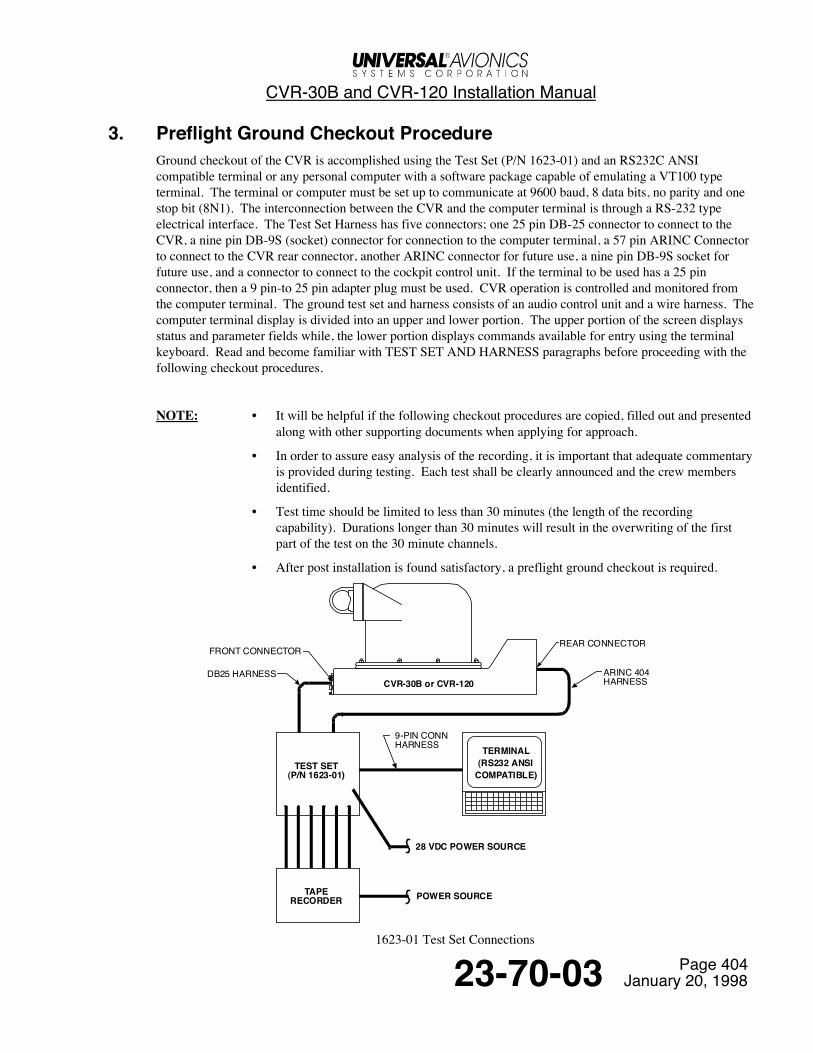
CVR-30B and CVR-120 Installation Manual
Page 40423-70-03 January 20, 1998
3. Preflight Ground Checkout ProcedureGround checkout of the CVR is accomplished using the Test Set (P/N 1623-01) and an RS232C ANSIcompatible terminal or any personal computer with a software package capable of emulating a VT100 typeterminal. The terminal or computer must be set up to communicate at 9600 baud, 8 data bits, no parity and onestop bit (8N1). The interconnection between the CVR and the computer terminal is through a RS-232 typeelectrical interface. The Test Set Harness has five connectors; one 25 pin DB-25 connector to connect to theCVR, a nine pin DB-9S (socket) connector for connection to the computer terminal, a 57 pin ARINC Connectorto connect to the CVR rear connector, another ARINC connector for future use, a nine pin DB-9S socket forfuture use, and a connector to connect to the cockpit control unit. If the terminal to be used has a 25 pinconnector, then a 9 pin-to 25 pin adapter plug must be used. CVR operation is controlled and monitored fromthe computer terminal. The ground test set and harness consists of an audio control unit and a wire harness. Thecomputer terminal display is divided into an upper and lower portion. The upper portion of the screen displaysstatus and parameter fields while, the lower portion displays commands available for entry using the terminalkeyboard. Read and become familiar with TEST SET AND HARNESS paragraphs before proceeding with thefollowing checkout procedures.
NOTE: • It will be helpful if the following checkout procedures are copied, filled out and presented along with other supporting documents when applying for approach.
• In order to assure easy analysis of the recording, it is important that adequate commentaryis provided during testing. Each test shall be clearly announced and the crew membersidentified.
• Test time should be limited to less than 30 minutes (the length of the recordingcapability). Durations longer than 30 minutes will result in the overwriting of the firstpart of the test on the 30 minute channels.
• After post installation is found satisfactory, a preflight ground checkout is required.
CVR-30B or CVR-120
TEST SET(P/N 1623-01)
TAPERECORDER
TERMINAL(RS232 ANSI
COMPATIBLE)
28 VDC POWER SOURCE
POWER SOURCE
FRONT CONNECTOR
DB25 HARNESS
REAR CONNECTOR
ARINC 404HARNESS
9-PIN CONNHARNESS
1623-01 Test Set Connections

CVR-30B and CVR-120 Installation Manual
Page 40523-70-03 January 20, 1998
A. Checkout ProceduresWARNING: USE ONLY P/N 1623-01 TEST SET AND HARNESS FOR CVR TESTING. FAILURE
TO COMPLY COULD DAMAGE THE CVR AND VOID THE WARRANTY.
NOTE: Refer to the wiring diagrams and information inside the lid on the Test Set, it will be helpful when connecting the Test Set to the CVR.
MECH INSP
(1) With all power removed from the aircraft, gain access to the Cockpit RecorderUnit.
(2) Verify the following switch positions on the Test Set:a) TEST SET POWER - Offb) CHANNEL SELECT Switches
PA - OffCOPILOT - OffPILOT - OffMIXED - OffAREA MIC - OffHI-FI AREA MIC - Off
c) GND EQ INTLK - Ond) REC ON - One) 24dB, 12dB and 6dB - Offf) All other switches - Off
(3) Connect the test set and harness (P/N 1623-01) to the recorder unit frontconnector.
(4) Connect an RS232C compatible terminal to the test set harness nine pinconnector.
(5) Set SPKR/HEADSET VOLUME to approximate mid-range. (6) Apply power to the terminal and turn it on, then apply aircraft power to the
CVR, then set the TEST SET POWER switch to ON (the Test Set receivespower from the CVR).
NOTE: A three-second delay in screen display change is normal between the CVR and some personal computers.
(7) On the computer, type in 5 (Self Test) and ENTER to initiate self test.(8) Self test will take approximately 15 seconds to perform. During self test, the
PASS and FAIL Lights on the CVR controller will alternately illuminate.MODE on the terminal screen will read SELF TEST. OPERATION will readTESTING. No incoming audio will be recorded during self test.
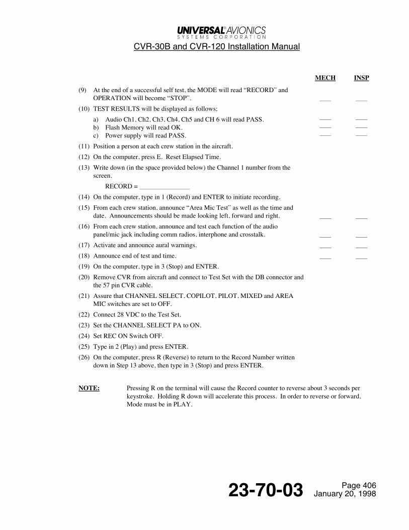
CVR-30B and CVR-120 Installation Manual
Page 40623-70-03 January 20, 1998
MECH INSP
(9) At the end of a successful self test, the MODE will read “RECORD” andOPERATION will become “STOP”.
(10) TEST RESULTS will be displayed as follows;a) Audio Ch1, Ch2, Ch3, Ch4, Ch5 and CH 6 will read PASS.b) Flash Memory will read OK.c) Power supply will read PASS.
(11) Position a person at each crew station in the aircraft.(12) On the computer, press E. Reset Elapsed Time.(13) Write down (in the space provided below) the Channel 1 number from the
screen.RECORD =
(14) On the computer, type in 1 (Record) and ENTER to initiate recording.(15) From each crew station, announce “Area Mic Test” as well as the time and
date. Announcements should be made looking left, forward and right. (16) From each crew station, announce and test each function of the audio
panel/mic jack including comm radios, interphone and crosstalk. (17) Activate and announce aural warnings. (18) Announce end of test and time. (19) On the computer, type in 3 (Stop) and ENTER.(20) Remove CVR from aircraft and connect to Test Set with the DB connector and
the 57 pin CVR cable.(21) Assure that CHANNEL SELECT, COPILOT, PILOT, MIXED and AREA
MIC switches are set to OFF.(22) Connect 28 VDC to the Test Set.(23) Set the CHANNEL SELECT PA to ON.(24) Set REC ON Switch OFF.(25) Type in 2 (Play) and press ENTER.(26) On the computer, press R (Reverse) to return to the Record Number written
down in Step 13 above, then type in 3 (Stop) and press ENTER.
NOTE: Pressing R on the terminal will cause the Record counter to reverse about 3 seconds per keystroke. Holding R down will accelerate this process. In order to reverse or forward,Mode must be in PLAY.
CVR-30B and CVR-120 Installation Manual
Page 40723-70-03 January 20, 1998
MECH INSP
(27) Type in 2 (Play) and press ENTER.(28) Verify that the appropriate announcements and tests are on Channel 1 (PA) and
that conversation is intelligible. (29) Press R (Reverse) to return to the beginning of the recording.(30) On the computer, type in 3 (Stop) and press ENTER.(31) Repeat steps 23 thru 30 for Channels 2, 3, 4, 5 and 6 using the appropriate
CHANNEL SELECT Switches. (32) On the computer, type 4 (Bulk Erase) and press ENTER.(33) Verify that Bulk Erase process occurs.(34) Type in 3 (Stop) and press ENTER.(35) Remove all power and disconnect Test Set and computer from recorder. (36) Secure all equipment in preparation for flight checkout.
CVR-30B and CVR-120 Installation Manual
Page 40823-70-03 January 20, 1998
4. Flight Checkout ProcedureIt is common practice for local certifying agencies to require a recorded tape of the CVR flight checkoutprocedure. The P/N 1623-01 CVR Test Set incorporates six high level audio output jacks which can be used totransfer the Flight Checkout onto tape via an audio mixer. The recording is transferred onto tape during thepostflight portion of the Flight Checkout procedure.
NOTE: • It will be helpful if the following checkout procedures are copied, filled out and presented along with other supporting documents when applying for approval.
• Flight time should be limited to less than 30 minutes. Any duration longer than 30minutes will result in overwrite of the first part of the checkout.
Once the Ground Checkout Procedure is completed satisfactorily, the following Flight Checkout Procedure is tobe performed.
NOTE: In order to assure easy analysis of the recording it is important that adequate commentary is provided during the flight, e.g., crew actions, speed, altitude and equipment operation. Eachtest shall be clearly announced in a normal speaking voice and the crew member identified.Cockpit speakers should be set to the normal volume.
A. Prior To Engine StartMECH INSP
(1) Engage cockpit voice recorder circuit breaker. (2) Don headsets and boom microphones.(3) Perform CVR self test. (4) Select boom microphone and interphone ON at all positions(5) Announce aircraft type, registration, date, time and crew.
B. Engine StartMECH INSP
(1) On rotorcraft only, during rotor spin-up, announce RPM at 50%, 80% and100%.
(2) With interphone on, make an announcement from each crew member position. (3) With interphone off, make an announcement from each crew member position. (4) Repeat steps (2) and (3) using the oxygen mask microphone. (5) Test stall warning stick shaker and announce (if applicable). (6) Cockpit windows closed (if applicable).

CVR-30B and CVR-120 Installation Manual
Page 40923-70-03 January 20, 1998
C. Take-OffMECH INSP
(1) Turn interphone on. (2) Announce a normal take-off and initial climb. (3) Announce landing gear, flap and other selections. (4) With interphone off, activate and announce aural warnings. (5) Turn interphone back on. (6) Accelerate to normal cruise speed. (7) Announce from each crew station, name, altitude, and airspeed.
Announcements should be made looking left, forward and right. (8) Activate, and announce aural warnings. (9) Each crew member should verify selections of comms and navaids on their
respective audio control panel and perform a communications check usingcomms, interphone and P/A.
(10) Accelerate to maximum cruise speed. (11) Announce from each crew station, name, altitude and airspeed.
Announcements should be made looking let, forward and right. (12) Activate and announce aural warnings.
D. LandingMECH INSP
(1) Announce landing events such as final approach, ILS marker audio ID, landinggear selection, flap selection, etc.
(2) At the end of taxi, announce the time. (3) Using the boom microphone with interphone on at all positions, announce end
of test.
CAUTION: FAILURE TO PULL CVR CIRCUIT BREAKER COULD RESULT IN ACOMPLETE OVERWRITE OF THE FLIGHT TEST RECORDING IF THE CVR ISSTILL POWERED AFTER LANDING.
(4) Pull CVR Circuit Breaker (Do not erase).
CVR-30B and CVR-120 Installation Manual
Page 41023-70-03 January 20, 1998
E. PostflightUsing the Test Set (P/N 1623-01) along with a compatible terminal, perform the following;
WARNING: USE ONLY P/N 1623-01 TEST SET FOR CVR TESTING. FAILURE TO COMPLYCOULD DAMAGE THE CVR AND VOID THE WARRANTY.
NOTE: Test set P/N 1623-01 incorporates six high level audio out jacks. These unswitched outputs can be used to transfer the Flight Checkout onto tape via an audio mixer.
(1) With all power removed, gain access to the recorder unit and remove it from the aircraft.(2) Verify that the test set POWER Switch is OFF.(3) Connect +28 VDC and ground leads from power supply to Test Set +28V and GND jacks.(4) Connect the test set and harness (P/N 1623-01) to recorder unit front and rear connectors.(5) Connect an RS232C compatible terminal to the test set harness nine pin connector.(6) Set test set SPKR/HEADSET VOLUME to approximate mid range.(7) Set GND EQ INTLK Switch ON.(8) Set STOP REC Switch ON.(9) Set REC ON Switch ON.(10) Set EXT CVR-FDR PWR Switch ON.(11) Set the TEST SET POWER switch to ON.(12) Type in 3 (Stop) and press ENTER.(13) Write down (in the space provided below) the Record number from the upper portion of the screen.
RECORD = (14) Set CHANNEL SELECT Switches, except PA, to OFF.(15) Verify that CHANNEL SELECT PA Switch is ON.(16) Type in 2 (Play) and press ENTER.(17) On the computer, press R (Reverse) to return to the Record Number recorded in step (9) above, then type
in 3 (Stop) and enter.NOTE: • Pressing R on the terminal will cause the Record counter to reverse 3 seconds per
keystroke. Holding R down will accelerate this process. In order to reverse or forward.Mode must be in PLAY.
• On rotorcraft, during the following tests, note rotor speed frequency on the computerscreen as RPM is announced by the crew. The rotorcraft manufacturer must be contactedfor the Hz to RPM conversion factor for RPM verification.
(18) On the computer, type in 2 (Play) and press ENTER.(19) Verify that the appropriate announcements and tests are on the PA Channel and that conversation is
intelligible.(20) Press R (Reverse) to return to the beginning of the recording.(21) On the computer type in 3 (Stop) and press ENTER.(22) Repeat step (14) thru (21) for COPILOT, PILOT, MIXED, AREA MIC and HI-FI AREA MIC Channels.

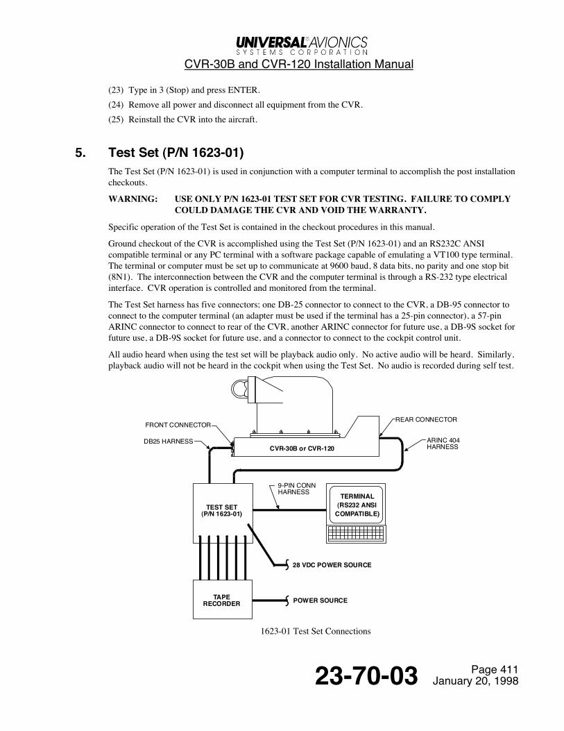
CVR-30B and CVR-120 Installation Manual
Page 41123-70-03 January 20, 1998
(23) Type in 3 (Stop) and press ENTER.(24) Remove all power and disconnect all equipment from the CVR.(25) Reinstall the CVR into the aircraft.
5. Test Set (P/N 1623-01)The Test Set (P/N 1623-01) is used in conjunction with a computer terminal to accomplish the post installationcheckouts.
WARNING: USE ONLY P/N 1623-01 TEST SET FOR CVR TESTING. FAILURE TO COMPLYCOULD DAMAGE THE CVR AND VOID THE WARRANTY.
Specific operation of the Test Set is contained in the checkout procedures in this manual.
Ground checkout of the CVR is accomplished using the Test Set (P/N 1623-01) and an RS232C ANSIcompatible terminal or any PC terminal with a software package capable of emulating a VT100 type terminal.The terminal or computer must be set up to communicate at 9600 baud, 8 data bits, no parity and one stop bit(8N1). The interconnection between the CVR and the computer terminal is through a RS-232 type electricalinterface. CVR operation is controlled and monitored from the terminal.
The Test Set harness has five connectors; one DB-25 connector to connect to the CVR, a DB-95 connector toconnect to the computer terminal (an adapter must be used if the terminal has a 25-pin connector), a 57-pinARINC connector to connect to rear of the CVR, another ARINC connector for future use, a DB-9S socket forfuture use, a DB-9S socket for future use, and a connector to connect to the cockpit control unit.
All audio heard when using the test set will be playback audio only. No active audio will be heard. Similarly,playback audio will not be heard in the cockpit when using the Test Set. No audio is recorded during self test.
CVR-30B or CVR-120
TEST SET(P/N 1623-01)
TAPERECORDER
TERMINAL(RS232 ANSI
COMPATIBLE)
28 VDC POWER SOURCE
POWER SOURCE
FRONT CONNECTOR
DB25 HARNESS
REAR CONNECTOR
ARINC 404HARNESS
9-PIN CONNHARNESS
1623-01 Test Set Connections
CVR-30B and CVR-120 Installation Manual
Page 41223-70-03 January 20, 1998
A. Test Set Features (Refer to the Test Set Panel Layout figure)(1) CHANNEL SELECT Switches - Six channel select switches allow selection or deselection of each of
the six channels. This allows selection of playback of individual or any combination of channels to thehigh level audio output jacks and the speaker.
(2) SIGNAL LEVEL Indicator - The ten segment bar graph on the Test Set remains active during bothrecord and playback when the CTRL UNIT EXT/OFF/INT slide switch is in the INT position and whenthe GND EQ INTLK push-button switch is ON. During playback, the bargraph will flash about once persecond when playing out previously recorded FSK data, and will indicate the playback audio for aparticular channel when selected with the CHANNEL SELECT push-buttons.
(3) SPKR/HEADSET VOLUME Adjustment - The speaker volume adjusts the level of audio to the TestSet speaker. The CHANNEL SELECT push-buttons determine which channel or channels will beapplied to the speaker.
(4) LO LEVEL AUDIO OUT for Cassette Recorder - This low level (10-20mV) output jack is forconnection to a cassette recorder. The jack outputs any of the channels as selected by the CHANNELSELECT Switches. The six channel output is adjustable by using the LVL ADJUST Potentiometer.
(5) HI LEVEL AUDIO OUT - This high level (330mV) jack is for connection to the line input of a stereorecorder via an RCA jack. The jack outputs any of the six channels as selected by the CHANNELSELECT Switches.
(6) HEADSET Jack - When a headset is used in lieu of the test set integral speaker, plugging the headsetinto the jack will mute the integral speaker.
(7) SCOPE OUTPUT - A coaxial connector exists to be used in applications where it is desirable to monitoraudio output with an oscilloscope or a voltmeter. This is normally an overhaul facility application.
(8) HI-LEVEL AUDIO OUTPUTS - These six unswitched jacks provide unswitched outputs fortransferring CVR recording onto a tape via an audio mixer. The jacks are labeled PA, COPILOT,PILOT, MIXED, AREA MIC and HI-FI AREA MIC.
(9) TEST SET POWER Switch - This switch applies power to all of the internal electronics of the Test Setand must be ON when using the Test Set. The Test Set power comes from the CVR-120/30B through theDB25 connector on the front of the CVR. This switch does not effect power to the CVR.
(10) Speaker - The speaker is provided to listen to playback audio from the CVR. Selection of which channelto listen to is provided by the CHANNEL SELECT push-button switches to the right of the HI LEVELAUDIO OUT jack on the Test Set.
(11) GND EQ INTLK Switch - This push-button switch informs the CVR that the Test Set has beenconnected. This switch must be illuminated (ON) when using the Test Set with the CVR, even when theCVR is installed on an aircraft. When the CVR is installed on an aircraft and connected to the Test Set,this push-button switch, when ON, will inhibit CVR recording after applying power to the CVR.
(12) REC ON Switch - This switch must also be ON when recording test speech or tones from the Test Setwhen the CVR is connected to the Test Set and not installed on an aircraft. When this switch is OFF,recording from the Test Set is inhibited, and bulk erase is not allowed. In addition, when this switch isON, playback is inhibited. Recording and playback of audio to/from the Test Set is always inhibitedwhen the CVR is installed on an aircraft.
CVR-30B and CVR-120 Installation Manual
Page 41323-70-03 January 20, 1998
(13) STOP REC Switch - With this switch placed to the ON position, while previously recording, will start aten minute timer that will terminate recording after the timer expires. This push-button switch setting isignored when power is first applied to the CVR. In other words, the CVR must see this switch go fromthe inactive to the active position in order to be properly recognized. When the CVR is installed on anaircraft, the STOP REC switch on the Test Set has no effect on CVR operation.
(14) LOOP BACK Switch - This push-button switch, when placed to the ON position with the Test Set -connected to the CVR, will indicate to the CVR that external loopback testing of the unit is desired.Individual tests can be selected at the terminal. Signals are actually transmitted out of the CVR throughthe Test Set and back into the CVR to complete the “loop” test. Signals tested during Loop Back are; allfour audio input channels, FSK, rotor speed, and all of the ARINC 429 transmit and receive channels.When the CVR is installed in the aircraft, the LOOP BACK switch has no effect on CVR operation.
(15) TEST Switch - This momentary switch initiates a self test when the CONTROL UNIT INT/OFF/EXTswitch has been set to INT, and is identical to pushing the TEST switch on an external control unit. Alltesting is confined within the CVR when the LOOP BACK switch is OFF. When the LOOP BACKswitch is ON the test signals are routed through the Test Set in order to test pin and cable continuity. Ifan external control unit is connected to the Test Set and properly connected to the CVR and the CTRLUNIT INT/OFF/EXT slide switch has been set to EXT, the TEST switch on the external control unit canbe pressed to initiate a test. When the CVR is installed on an aircraft, the TEST switch has no effect onCVR operation.
(16) DELAYED REC INHB Switch - This switch is not used for testing of the CVR-120/30B.(17) BULK ERASE Switch - If the CTRL UNIT INT/OFF EXT switch has been set to INT, REC ON is ON
and STOP REC has not timed out (10 minutes), this momentary push-button switch will initiate a bulkerase of the entire flash memory array, assuming that GND EQ INTLK is ON. This switch emulates theBulk Erase switch on an external control unit. If an external control unit is connected to the Test Set andthe Test Set is properly connected to the CVR, the BULK ERASE switch on the external control unit canbe pressed to initiate a bulk erase. When the CVR is installed on an aircraft, the BULK ERASE switchhas no effect on CVR operation.
(18) MONITOR Switch - This push-button switch selects mixed audio to be tested on the Test Set’s bargraph from two possible sources; 1) mixed audio that drives the headset jack on an external control unit,or 2) mixed audio that drives the bar graph on an external control unit. When the CVR is installed on anaircraft, the MONITOR switch has no effect on CVR operation.
(19) 24dB, 12dB and 6dB Attenuation Switches - These push-button switches select attenuation settings forthe Test Set’s mic amplifier when the CONTROL UNIT INT/OFF/EXT switch has been set to INT, andfor an external control unit’s mic amplifier when properly connected to the Test Set with the cableprovided and the CTRL UNIT INT/OFF/EXT switch set to EXT.
(20) CTRL UNIT Switch:INT Position - Selects the Test Set’s internal control unit for test recording of speech.OFF Position - No selection of a control unit. Therefore, audio signals picked up by the internalmicrophone in the Test Set will not interfere with any other testing that is being performed.EXT Position - Selects an external control unit connected to the Test Set for testing. The externalcontrol unit must be connected to the Test Set with the cable provided.
(21) FSK IN/OUT Coax Connector - This jack allows the connection of an external FSK signal for testingpurposes. The FSK input signal can be either a sinewave or triangle wave of 3607 Hz or 4193 Hz.During normal playback of audio during storage retrieval, this jack is used to play back the previouslyrecorded time data in an FSK analog format. The analog output level is approximately 1 Vrms sinewaveat a rate of once per second, regardless of the recorded rate. When the CVR is installed on an aircraft, theFSK IN/OUT jack has no effect on CVR operation.

CVR-30B and CVR-120 Installation Manual
Page 41423-70-03 January 20, 1998
(22) RTR SP IN/OUT Coax Connector - This jack allows the connection of an external rotor speed signalfrom 10 Hz to 15,000 Hz for testing purposes. The input sinewave can be in the range of 100 mV to 1Vrms. During normal playback of audio during storage retrieval, this jack is used to play back thepreviously recorded rotor speed data in an analog format. The output level is about 1 Vrms. When theCVR is installed on an aircraft, the RTR SP IN/OUT jack has no effect on CVR operation.
(23) TEST INPUTS - PA, COPILOT, PILOT and AREA MIC Coax Connectors - These four input jacksprovide a means of connecting an external signal to each of the four CVR audio input channels for audiorecording test purposes.
(24) AREA MIC Switch - This push-button switch selects the Lo-Fi Area Mic output audio from the CVR tobe connected to the Test Set’s HI LEVEL AUDIO OUT jack, HEADSET jack, LO LEVEL AUDIOOUT jack, SCOPE jack, and the Test Set’s internal speaker for testing. If any of the other push-buttonswitches (e.g., PA, COPILOT, PILOT, MIXED, AREA MIC) are ON, the audio signal from thesechannels will be mixed with the Lo-Fi Area Mic audio output from the CVR.
(25) HI-FI AREA MIC Switch - This push-button selects the Hi-Fi Area Mic audio output from the CVR tobe connected to the Test Set’s HI LEVEL AUDIO OUT jack, HEADSET jack, LO LEVEL AUDIOOUT jack, SCOPE jack, and the Test Set’s internal speaker for testing. If any of the other push-buttonswitches (e.g., PA, COPILOT, PILOT, MIXED, AREA MIC) are on, the audio signal from thesechannels will be mixed with the Hi-Fi Area Mic audio output from the CVR.
(26) MIXED Switch - This push-button selects the mixed audio output from the CVR, which consists ofPA/Copilot/Pilot audio to be connected to the Test Set’s HI LEVEL AUDIO OUT jack, HEADSET jack,LO LEVEL AUDIO OUT jack, SCOPE jack and the Test Set’s internal speaker for testing. If any of theother push-button switches (e.g., PA, COPILOT, PILOT, MIXED, AREA MIC) are ON, the audio signalfrom these channels will be mixed with the mixed audio output from the CVR.
(27) PASS and FAIL Indicators - These LEDs indicate various test conditions and are identical to theindicators on an external control unit. The CTRL UNIT INT/OFF/EXT slideswitch must be in the INTposition for these indicators to function.
(28) EXT CVR-FDR PWR Switch - Applies 28 VDC power to the CVR when the CVR is connected to theTest Set via the rear connector. Power is applied to the CVR regardless of the position of the TEST SETPWR switch setting. Power cannot be applied from the Test Set to the CVR when the connector on thefront panel of the CVR alone is connected to the Test Set. This switch has no affect when the CVR isinstalled on an aircraft or receives its power from another source.
(29) +28VDC and GND Jacks - These jacks allow an external power supply to power the CVR when theTest Set is connected to the CVR rear connector. The power supply must be able to provide about800mA of continuous current with an initial power on surge of about 1.5 amps. The CVR draws about400mA and the Test Set and external control unit draw about 200mA each, depending on how manyswitches and segments on the bar graph are illuminated.A power supply connected to these jacks will not power the CVR when installed on an aircraft becausethe CVR is receiving its power from the aircraft and not the Test Set.
(30) FDR DATA Switch - The Flight Data Recorder switch is a future provision however, it must be set tothe 64W position.
(31) INT MIC - The Test Set internal microphone is used to input recorded speech to the CVR via the TestSet.
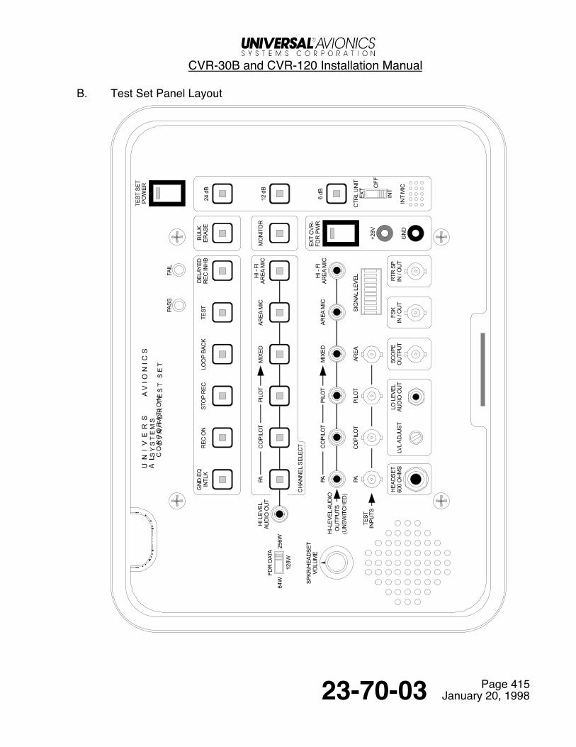
CVR-30B and CVR-120 Installation Manual
Page 41523-70-03 January 20, 1998
B. Test Set Panel Layout

CVR-30B and CVR-120 Installation Manual
Page 41623-70-03 January 20, 1998
C. ANSI Terminal InterfaceIn addition to the features described above, the test set and harness, when connected to an RS232C ANSIterminal (or any PC with a software package capable of emulating a VT100 type terminal), includes thefollowing features which can be seen and controlled on the terminal. The terminal screen is divided into anupper portion and a lower portion. The upper portion provides information while the lower portion indicates thevarious modes.

CVR-30B and CVR-120 Installation Manual
Page 41723-70-03 January 20, 1998
Upper Portion of Screen:
(1) MODE - Displays the active mode; record, playback, self test, bulk erase and calibration.(2) OPERATION - Displays the current operation; recording, playing, stopped, erasing, testing and
calibration.(3) ELAPSED TIME - Displays in hours: minutes: seconds. The elapsed timer is reset using ‘R’ command
on the keyboard.(4) ROTOR SPEED - Rotor speed is displayed in Hz when a valid rotor speed input is provided. When
there is no rotor speed input, it will read - - - -Hz.(5) RECORD - This number is used to find a specific spot on the recording.(6) RECORD HOURS - Displays the total number of hours that the recorder has accumulated. Used for
inspection/maintenance purposes.(7) SELF TEST RESULTS - Self Test results for CVR Fault, Flash Memory, Power Supply and Audio.
CVR FAULT - Will display “ON” or “OFF”.Flash Status - Will display either OK or FAIL.Power Supply Test - Will display either PASS or FAIL as well as power supply voltages for +5V,filtered +5V, -5V, +12V, -12V and Input Voltage.Audio Test - Each of the six channel fields will display either PASS or FAIL.DUART Inputs - Not used by field installation personnel.Para Inputs - Not used by field installation personnel.
(8) Channel, Record - This field displays the record number for each of the six channels. This gives anindication of the relative position in the audio buffer. 30 min audio buffers may display dashes for therecord number if the audio buffer is inactive at the time. This occurs for the first 90 minutes of a 120minute channel during playback mode.
(9) ARINC 429 GMT - Displays the current time detected by the ARINC 429 GMT bus during recordmode. Field is dashed during recording when GMT is not present. During playback, the displayrepresents GMT as recorded in flash memory.
(10) FSK GMT - Displays the current time detected by the FSK GMT bus during record mode. Field isdashed during recording when FSK GMT is not present. During playback, the display represents FSKGMT as recorded in flash memory.
(11) BITE Status - Not used by installation personnel.
CVR-30B and CVR-120 Installation Manual
Page 41823-70-03 January 20, 1998
Lower Portion of Screen:
(1) 1. Record - Typing 1 and pressing enter will begin recording.(2) 2. Play - Typing 2 and pressing enter will begin play. When Play is entered immediately after Record,
the play will start at the beginning of the recording. Entering Play momentarily during recording modewill leave an index that the play mode will begin at the next time it is entered.
(3) 3. Stop - Typing 3 and pressing enter will stop the record or play mode.(4) 4. Bulk Erase - Typing 4 and pressing enter will initiate the bulk erase mode.(5) 5. Self Test - Typing 5 and pressing enter will initiate self test.(6) F = Forward - Pressing F while in the play mode will cause the recording to skip forward at a rate of 100
records (approx. 3 seconds) per keystroke. Holding F down will accelerate this rate.(7) C = System Calibration - Pressing C on the terminal initiates an internal audio calibration. Before
calibrating, the 24dB, 12dB, 6dB attenuation switches on the Test Set must be off or the CTRL UNITSwitch on the Test Set must be OFF.
(8) R = Reverse - Pressing R while in the play mode will cause the recording to reverse at a rate of 100records (approx. 3 seconds) per keystroke. Holding R down will accelerate this rate.
(9) CTRL+F = Fast Forward - Pressing Control and F will cause the recording to skip forward at a rate of1000 records (approximately 30 seconds) per keystroke. Holding F down will accelerate this rate.
(10) CTRL+R = Fast Reverse - Pressing Control and R will cause the recording to skip back at a rate of 1000records (approximately 30 seconds) per keystroke. Holding R down will accelerate this rate.
(11) E = Reset Elapsed Time - Pressing E will zero out the Elapsed Time.
Return to Table of Contents